JP2013545057A - Geometry concept for roller-to-collar contact in roller bearings - Google Patents
Geometry concept for roller-to-collar contact in roller bearings Download PDFInfo
- Publication number
- JP2013545057A JP2013545057A JP2013542456A JP2013542456A JP2013545057A JP 2013545057 A JP2013545057 A JP 2013545057A JP 2013542456 A JP2013542456 A JP 2013542456A JP 2013542456 A JP2013542456 A JP 2013542456A JP 2013545057 A JP2013545057 A JP 2013545057A
- Authority
- JP
- Japan
- Prior art keywords
- collar
- surface section
- roller
- spherical
- collar surface
- Prior art date
- Legal status (The legal status is an assumption and is not a legal conclusion. Google has not performed a legal analysis and makes no representation as to the accuracy of the status listed.)
- Pending
Links
Images


Classifications
-
- F—MECHANICAL ENGINEERING; LIGHTING; HEATING; WEAPONS; BLASTING
- F16—ENGINEERING ELEMENTS AND UNITS; GENERAL MEASURES FOR PRODUCING AND MAINTAINING EFFECTIVE FUNCTIONING OF MACHINES OR INSTALLATIONS; THERMAL INSULATION IN GENERAL
- F16C—SHAFTS; FLEXIBLE SHAFTS; ELEMENTS OR CRANKSHAFT MECHANISMS; ROTARY BODIES OTHER THAN GEARING ELEMENTS; BEARINGS
- F16C33/00—Parts of bearings; Special methods for making bearings or parts thereof
- F16C33/30—Parts of ball or roller bearings
- F16C33/58—Raceways; Race rings
- F16C33/64—Special methods of manufacture
-
- F—MECHANICAL ENGINEERING; LIGHTING; HEATING; WEAPONS; BLASTING
- F16—ENGINEERING ELEMENTS AND UNITS; GENERAL MEASURES FOR PRODUCING AND MAINTAINING EFFECTIVE FUNCTIONING OF MACHINES OR INSTALLATIONS; THERMAL INSULATION IN GENERAL
- F16C—SHAFTS; FLEXIBLE SHAFTS; ELEMENTS OR CRANKSHAFT MECHANISMS; ROTARY BODIES OTHER THAN GEARING ELEMENTS; BEARINGS
- F16C19/00—Bearings with rolling contact, for exclusively rotary movement
- F16C19/22—Bearings with rolling contact, for exclusively rotary movement with bearing rollers essentially of the same size in one or more circular rows, e.g. needle bearings
- F16C19/225—Details of the ribs supporting the end of the rollers
-
- F—MECHANICAL ENGINEERING; LIGHTING; HEATING; WEAPONS; BLASTING
- F16—ENGINEERING ELEMENTS AND UNITS; GENERAL MEASURES FOR PRODUCING AND MAINTAINING EFFECTIVE FUNCTIONING OF MACHINES OR INSTALLATIONS; THERMAL INSULATION IN GENERAL
- F16C—SHAFTS; FLEXIBLE SHAFTS; ELEMENTS OR CRANKSHAFT MECHANISMS; ROTARY BODIES OTHER THAN GEARING ELEMENTS; BEARINGS
- F16C19/00—Bearings with rolling contact, for exclusively rotary movement
- F16C19/22—Bearings with rolling contact, for exclusively rotary movement with bearing rollers essentially of the same size in one or more circular rows, e.g. needle bearings
- F16C19/34—Bearings with rolling contact, for exclusively rotary movement with bearing rollers essentially of the same size in one or more circular rows, e.g. needle bearings for both radial and axial load
- F16C19/36—Bearings with rolling contact, for exclusively rotary movement with bearing rollers essentially of the same size in one or more circular rows, e.g. needle bearings for both radial and axial load with a single row of rollers
- F16C19/364—Bearings with rolling contact, for exclusively rotary movement with bearing rollers essentially of the same size in one or more circular rows, e.g. needle bearings for both radial and axial load with a single row of rollers with tapered rollers, i.e. rollers having essentially the shape of a truncated cone
-
- F—MECHANICAL ENGINEERING; LIGHTING; HEATING; WEAPONS; BLASTING
- F16—ENGINEERING ELEMENTS AND UNITS; GENERAL MEASURES FOR PRODUCING AND MAINTAINING EFFECTIVE FUNCTIONING OF MACHINES OR INSTALLATIONS; THERMAL INSULATION IN GENERAL
- F16C—SHAFTS; FLEXIBLE SHAFTS; ELEMENTS OR CRANKSHAFT MECHANISMS; ROTARY BODIES OTHER THAN GEARING ELEMENTS; BEARINGS
- F16C33/00—Parts of bearings; Special methods for making bearings or parts thereof
- F16C33/30—Parts of ball or roller bearings
- F16C33/34—Rollers; Needles
- F16C33/36—Rollers; Needles with bearing-surfaces other than cylindrical, e.g. tapered; with grooves in the bearing surfaces
- F16C33/366—Tapered rollers, i.e. rollers generally shaped as truncated cones
-
- F—MECHANICAL ENGINEERING; LIGHTING; HEATING; WEAPONS; BLASTING
- F16—ENGINEERING ELEMENTS AND UNITS; GENERAL MEASURES FOR PRODUCING AND MAINTAINING EFFECTIVE FUNCTIONING OF MACHINES OR INSTALLATIONS; THERMAL INSULATION IN GENERAL
- F16C—SHAFTS; FLEXIBLE SHAFTS; ELEMENTS OR CRANKSHAFT MECHANISMS; ROTARY BODIES OTHER THAN GEARING ELEMENTS; BEARINGS
- F16C33/00—Parts of bearings; Special methods for making bearings or parts thereof
- F16C33/30—Parts of ball or roller bearings
- F16C33/58—Raceways; Race rings
- F16C33/583—Details of specific parts of races
- F16C33/585—Details of specific parts of races of raceways, e.g. ribs to guide the rollers
-
- F—MECHANICAL ENGINEERING; LIGHTING; HEATING; WEAPONS; BLASTING
- F16—ENGINEERING ELEMENTS AND UNITS; GENERAL MEASURES FOR PRODUCING AND MAINTAINING EFFECTIVE FUNCTIONING OF MACHINES OR INSTALLATIONS; THERMAL INSULATION IN GENERAL
- F16C—SHAFTS; FLEXIBLE SHAFTS; ELEMENTS OR CRANKSHAFT MECHANISMS; ROTARY BODIES OTHER THAN GEARING ELEMENTS; BEARINGS
- F16C2240/00—Specified values or numerical ranges of parameters; Relations between them
- F16C2240/40—Linear dimensions, e.g. length, radius, thickness, gap
- F16C2240/70—Diameters; Radii
-
- Y—GENERAL TAGGING OF NEW TECHNOLOGICAL DEVELOPMENTS; GENERAL TAGGING OF CROSS-SECTIONAL TECHNOLOGIES SPANNING OVER SEVERAL SECTIONS OF THE IPC; TECHNICAL SUBJECTS COVERED BY FORMER USPC CROSS-REFERENCE ART COLLECTIONS [XRACs] AND DIGESTS
- Y10—TECHNICAL SUBJECTS COVERED BY FORMER USPC
- Y10T—TECHNICAL SUBJECTS COVERED BY FORMER US CLASSIFICATION
- Y10T29/00—Metal working
- Y10T29/49—Method of mechanical manufacture
- Y10T29/49636—Process for making bearing or component thereof
- Y10T29/49643—Rotary bearing
- Y10T29/49679—Anti-friction bearing or component thereof
Landscapes
- Engineering & Computer Science (AREA)
- General Engineering & Computer Science (AREA)
- Mechanical Engineering (AREA)
- Manufacturing & Machinery (AREA)
- Rolling Contact Bearings (AREA)
Abstract
本発明は、少なくとも1つのころ(13)のための転動軌道(14;15)を有するころ軸受用の軸受レース(30)であって、ころ(13)は、第1の曲率を有する部分球状に形成されたころ端面(21)を有し、軸受レース(30)は、軸方向力を導出するために、ころ端面側のつば面(32)を有する、ころ端面に向かって配置されたつば(31)を備え、つば面(32)は、第2の曲率を有する球面状のつば面区分(33)を有し、第1の曲率と第2の曲率とは、球状に形成されたころ端面(21)と球面状のつば面区分(33)との間に第1の間隙寸法(d1)が得られるように選択されており、かつつば面(32)はさらに、拡開するつば面区分(34)を有し、拡開するつば面区分(34)は、ころ端面(21)と拡開するつば面区分(34)との間の、第1の間隙寸法(d1)より大きな間隙寸法(d2)のための、第2の曲率より小さな曲率を有している軸受レースに関する。The present invention is a bearing race (30) for a roller bearing having a rolling track (14; 15) for at least one roller (13), the roller (13) having a first curvature. A roller end surface (21) formed in a spherical shape, and the bearing race (30) is arranged toward the roller end surface having a collar surface (32) on the roller end surface side in order to derive an axial force. The collar (31) includes a collar (32) having a spherical collar surface section (33) having a second curvature, and the first curvature and the second curvature are formed in a spherical shape. The first gap dimension (d 1 ) is selected between the roller end face (21) and the spherical collar face section (33), and the calf face (32) is further expanded. The flange surface section (34) that has a flange surface section (34) and expands expands with the roller end surface (21). Between the field surface section (34), for the larger gap size than the first gap dimension (d 1) (d 2), relates to a bearing race has a smaller curvature than the second curvature.
Description
本発明は、ころ軸受におけるころ対つば接触、特に円錐ころ軸受における円錐ころ対つば接触に関するジオメトリコンセプトに関する。 The present invention relates to a geometry concept for roller-to-collar contact in roller bearings, and in particular to tapered roller-to-collar contact in tapered roller bearings.
ころ軸受、例えば円錐ころ軸受における案内つばは、直線状に形成されるか、又は球面状に形成される場合がある。直線状のつばは、主として、比較的小径の、ひいては比較的小さなつば幅を有するころ軸受のために使用される。この場合、つば幅は、利用可能なつば面上に所定の輪郭を形成するには、しばしば小さすぎる。球面状のつばは、大部分、比較的大径の、ひいては比較的大きなつば幅を有するころ軸受において使用される。球面状のつばは、ころ転動軌道側のつば形状を規定する半径が、半径の基点を実質的にころの回転軸線(ころ回転軸線)上に有することを特徴とし、ミスアライメントに基づく小さな誤差は許容されている。 A guide collar in a roller bearing, for example, a tapered roller bearing, may be formed in a linear shape or a spherical shape. Linear collars are mainly used for roller bearings having a relatively small diameter and thus a relatively small collar width. In this case, the collar width is often too small to form a predetermined contour on the available collar surface. Spherical collars are mostly used in roller bearings having a relatively large diameter and thus a relatively large collar width. A spherical collar is characterized in that the radius that defines the collar shape on the roller rolling track side has a base point of the radius substantially on the rotation axis of the roller (roller rotation axis), and a small error based on misalignment Is allowed.
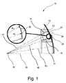
球面状のつばを有するころ軸受について詳説するために、図1に、概略的にころ軸受10の縦断面図を示した。このころ軸受10は、一例として円錐ころ軸受として形成されている。ころ軸受10は、1つの軸受内レース11と、1つの軸受外レース12と、複数のころ13とを有している。ころ13は、軸受レース11,12の内面により形成される転動面あるいは転動軌道14,15上を転動可能である。円錐ころ軸受の場合、ころあるいは転動体13は、相応に円錐ころである。
In order to explain in detail the roller bearing having a spherical collar, FIG. 1 schematically shows a longitudinal sectional view of the roller bearing 10. As an example, the roller bearing 10 is formed as a tapered roller bearing. The roller bearing 10 includes one bearing
円錐ころ13は、軸受内レース11に作り込まれた内側の転動軌道14及び軸受外レース12に作り込まれた外側の転動軌道15上を転動可能である。転動軌道14,15は、円錐ころ軸受の場合、3次元的に観察すると、円錐形周面として形成されている。円錐ころ軸受10の、図1に示した縦断面図で見て、転動軌道14,15は、転動軌道14,15をそれぞれ仮想的に延長した延長線として、ころ軸受10の回動軸線あるいは回転軸線18上で回転点19において交差する内側の直線16と外側の直線17とを規定している。
The
軸受10の運転中、各(円錐)ころ13は、自己のころ軸線20周りに自転する。ころ軸線20の仮想の延長線も、回転点19を通る。回転点19において交差する内側の直線16、外側の直線17、軸受回転軸線18及びころ軸線20の相対位置により、円錐ころ13のために、転がり条件が転動軌道14,15上に実現されているので、軸受内レース11と軸受外レース12との相対回動時、円錐ころ13は、転動軌道14,15上を実質的にスリップなしに転動し、これに関する滑り摩擦成分は、最小化されている。
During operation of the
軸方向、すなわち軸受回転軸線18の方向でも、軸方向力を受けたときに発生する摩擦を最適化するために、ころ軸受の場合、使用されるころ13の端面21は、第1の半径R21により規定される第1の曲率を有していてよい。その結果、ころ13の端面として、部分球面が生じる。部分球面は、図1の拡大図に概略的に示すように、接触点22において、例えば軸受内レース11の、直線状あるいは球面状に形成されたつば23と接触する。所定の接触点22を得るために、球面状に湾曲したつば面は、ころ13の球状の端面21の第1の曲率より小さな、第2の半径R23により規定される第2の曲率を有している。
In the case of a roller bearing, the
直線状あるいは平面状のつばを備えて形成されているころ軸受、例えば円筒ころ軸受、球面ころ軸受又は円錐ころ軸受の場合、ころ対つば接触は、球面状に形成されるつばと比較してより高い面圧(ヘルツ応力)を、ころ端面21と、ころ端面21側のつば面との間に有している。ここで、ヘルツ応力とは、2つの弾性体の接触面の中央部に支配する最大の応力と解される。直線状のつばを備えるころ軸受の場合のように、2つの弾性体(湾曲したころ端面及び直線状あるいは平面状のつば)が互いに押し付けられると、両者は、理想的には点状にのみ接触する。しかし、現実には、弾性により、接触点22において偏平化が生じ、これにより接触面が生じる。接触面上には、両弾性体内に、特徴的な応力分布(面圧)が発生する。応力は、常に中央部において最大である。このように、球表面と平面状のつば面とが接触すると、接触楕円又はコンタクトエリプスが生じる。比較的高い面圧に基づいて、直線状のつばを備えるころ軸受の場合、一般に、作用する力が比較的高いとき、比較的悪質な潤滑膜構造が生じる。さらに、直線状あるいは平面状のつばは、球面状のつばと比較して、ころ端面と、ころ端面側のつば面との間のより小さな接触楕円を伴う。したがって、つば縁部と接触楕円との交差は、極端な負荷時にのみ発生し得る。また、一般に、直線状あるいは平面状に形成されたつばの場合、ミスアライメントに対する接触点22の低い敏感性が生じるので、ころ13とつばとの間の所定の接触点22が可能である。平面状に形成されたつばの場合、ころ13の比較的大きな傾斜位置が可能となる一方、転動中のころの比較的悪い案内が生じる。
In the case of roller bearings formed with linear or planar collars, for example cylindrical roller bearings, spherical roller bearings or tapered roller bearings, the roller-to-collar contact is more in comparison with the spherically formed collars. A high surface pressure (Hertz stress) is provided between the
大型軸受分野の円錐ころ軸受は、図1に示すように、球面状のつば23を備えて形成され得る。このことは、直線状あるいは平面状のつばと比較して、ころ端面21と、ころ13側のつば面との間の比較的小さな面圧を結果として伴う。さらに、球面状に形成されたつば23は、直線状のつばと比較して、ころ端面21と、ころ端面21に対向するつば面との間の比較的大きな接触楕円を伴う。その結果、より頻繁に、つば縁部と接触楕円との交差、ひいてはエッジ応力が発生し得る。一般に、球面状に形成されたつば23の場合、平面状あるいは直線状に形成されたつばの場合と比較して、ミスアライメントに対する接触点22の比較的高い敏感性が生じる。球面状のつばは、一方では、ころ13の比較的小さな傾斜位置を結果として伴うものの、他方では、ころ端面21と、ころ13側のつば面との間の狭隘な接面に基づいて、ころ13は、転動中、より良好に案内され得る。ころ端面21及び球面状のつば面の曲率半径(及び/又はその基点)をそれぞれ異なって選択することにより、球面状のつばによっても、理論的には、ころ13とつば23との間の所定の接触点22が可能である。
A tapered roller bearing in the field of large bearings can be formed with a
しかし、球面状のつばの主な欠点の1つは、結果として生じる、ミスアライメントに関するころ端面21とつば23との間の接触点22の敏感性である。接触点22の敏感性に対して、転動軌道角度、ころ角度、つば半径及びころ端面半径における誤差は、決定的な影響を有している。
However, one of the main drawbacks of the spherical collar is the resulting sensitivity of the
したがって本発明の課題は、ミスアライメントに関するころ端面とつばとの間の接触点の敏感性を軽減することである。 Therefore, the subject of this invention is reducing the sensitivity of the contact point between the roller end surface regarding a misalignment, and a collar.
ミスアライメントに関するころ対つば接触点の敏感性を軽減し、それにもかかわらず転動中のころの十分な案内を保証することができるように、本発明は、相応に最適化されたつば面ジオメトリを提案する。提案するつば面ジオメトリは、このために、一方では、ころ案内及び低いヘルツ応力を保証する球面状のつば面区分を有している。他方、提案するつばジオメトリは、純然たる球面状に形成されたつばによるものと比較して、ころ端面と、ころ端面側のつば面との間のより大きな間隙寸法、すなわち、より大きな間隔を形成する区分(以下、拡開するつば面区分という。)を有している。 In order to reduce the sensitivity of the roller-to-collar contact point with respect to misalignment and nevertheless ensure adequate guidance of the rolling roller, the present invention provides a correspondingly optimized collar surface geometry. Propose. The proposed collar geometry thus has, on the one hand, a spherical collar section that guarantees roller guidance and low Hertz stress. On the other hand, the proposed brim geometry forms a larger gap dimension between the roller end face and the collar face on the roller end face side, i.e., a larger spacing, compared to a purely spherical collar. (Hereinafter, referred to as an expanded brim surface section).
本発明の態様は、このために、少なくとも1つのころのための転動軌道を有するころ軸受用の軸受レースであって、ころが、第1の曲率を有する少なくとも部分的に球状に形成されたころ端面を有している軸受レースを前提とする。軸受レースは、軸方向力を導出するために、ころ端面側のつば面を有する、ころ端面に向かって配置されたつばを備え、つば面は、第2の曲率を有する球面状のつば面区分を有している。第2の曲率は、球面状のつば面区分上に一定又は可変に形成されていてよい。第1の曲率と第2の曲率とは、球状に形成されたころ端面と球面状のつば面区分との間に、(ころ対つばのジオメトリ次第では平均的な間隙寸法であってもよい)第1の間隙寸法が得られるように選択されている。さらにつば面は、拡開するつば面区分を有し、拡開するつば面区分は、ころ端面と拡開するつば面区分との間の、第1の間隙寸法より大きな間隙寸法のための、第2の曲率より小さな曲率を有している。 An aspect of the invention is for this purpose a bearing race for a roller bearing having a rolling track for at least one roller, the roller being at least partly spherical with a first curvature. Assume a bearing race with roller end faces. The bearing race includes a collar disposed toward the roller end surface having a collar surface on the roller end surface side for deriving an axial force, and the collar surface is a spherical collar surface section having a second curvature. have. The second curvature may be formed constant or variably on the spherical collar surface section. The first curvature and the second curvature are between the spherically formed roller end face and the spherical collar surface section (may be an average gap size depending on the roller-to-collar geometry). A first gap dimension is selected to be obtained. In addition, the collar surface has an expanding collar surface section, the expanding collar surface section for a gap dimension greater than the first gap dimension between the roller end face and the expanding collar surface section, The curvature is smaller than the second curvature.
別の観点では、少なくとも1つのころのためのころ転動軌道を有するころ軸受用の軸受レースを製造する方法であって、ころが、第1の曲率を有する球状に形成されたころ端面を有している方法も提供される。本発明に係る方法は、ころ端面側のつば面を有する、軸方向力を導出するためにころ端面に向かって配置されるつばを準備するステップを有し、つばを準備するステップ自体は:
‐つば面の球面状のつば面区分を準備するステップであって、球面状のつば面区分が、球状に形成されたころ端面と球面状のつば面区分との間に第1の間隙寸法が得られるように第1の曲率に対して選択された第2の曲率を有するようにするステップと、
‐つば面の拡開するつば面区分を形成するステップであって、拡開するつば面区分が、球状に形成されたころ端面と拡開するつば面区分との間に第1の間隙寸法より大きな間隙寸法が得られるように第2の曲率より小さな曲率を有するようにするステップと、
を有する。
In another aspect, a method of manufacturing a bearing race for a roller bearing having a roller rolling raceway for at least one roller, the roller having a spherical end surface having a first curvature. A method is also provided. The method according to the invention comprises the steps of providing a collar having a flange face on the roller end face side, arranged towards the roller end face to derive axial force, the step of preparing the collar itself:
-A step of preparing a spherical collar surface section of the collar surface, wherein the spherical collar surface section has a first gap dimension between the spherically formed roller end face and the spherical collar surface section; Having a second curvature selected for the first curvature as obtained;
-A step of forming a flange surface section that expands the collar surface, wherein the collar surface section to be expanded is less than the first gap dimension between the spherically formed roller end surface and the flange surface section to be expanded; Having a curvature smaller than the second curvature so as to obtain a large gap dimension;
Have
好ましい態様において、球面状のつば面区分の第2の曲率は、一定又は可変に形成されていてよい。 In a preferred embodiment, the second curvature of the spherical collar surface section may be formed constant or variable.
好ましい態様において、拡開するつば面区分の代わりにこの領域で仮想的に純粋な球面状に延びるつば面における第1の接線平面と、拡開するつば面区分における第2の接線平面とは、0°より大きく30°以下である最大の角度αを形成する。 In a preferred embodiment, the first tangent plane at the flange surface extending in a virtually pure spherical shape in this region instead of the expanding flange surface section and the second tangent plane at the expanding flange surface section are: A maximum angle α that is greater than 0 ° and less than or equal to 30 ° is formed.
好ましい態様において、球面状のつば面区分は、つば面の少なくとも3分の1の領域にわたって延在する。 In a preferred embodiment, the spherical collar surface section extends over an area of at least one third of the collar surface.
幾つかの好ましい態様において、球面状のつば面区分は、転動軌道とつば面との間の角隅領域からつばの半径方向の端部あるいはつば縁部に向かって延びている。つまり、球面状のつば面区分は、軸受内レースの場合、つばの、内側の転動面側の下側の領域に、つば縁部あるいは溝縁部(Einstichkante)に隣接して位置することができ、この場合、拡開するつば区分は、球面状のつば面区分に隣接して、つばの上側の領域に位置している。軸受外レースの場合、その関係は相応に反転される。すなわち、この場合、球面状のつば面区分は、つばの上側の領域に、つば縁部あるいは溝縁部に隣接して位置しており、拡開するつば面区分は、つばの、外側の転動面とは反対側の下側の領域に位置している。 In some preferred embodiments, the spherical collar surface section extends from the corner area between the rolling track and the collar surface towards the radial end or collar edge of the collar. In other words, in the case of an inner race, the spherical collar surface section may be located in the lower region of the inner rolling surface side of the collar, adjacent to the collar edge or the groove edge (Einstichkante). In this case, the expanding collar section is located in the upper area of the collar adjacent to the spherical collar section. In the case of an outer bearing race, the relationship is reversed accordingly. That is, in this case, the spherical collar surface section is located in the upper area of the collar and adjacent to the collar edge or groove edge, and the expanding collar surface section is the outer rolling surface of the collar. It is located in the lower area opposite the moving surface.
しかし、別の好ましい態様では、球面状に形成されたつば面区分を転動軌道とつばとの間のつば縁部に隣接させず、拡開するつば面区分が球面状のつば面区分の上下に設けられているようにしてもよい。この場合、第1の拡開するつば面区分は、転動軌道とつば面との間の角隅領域から延び、半径方向で第1の拡開するつば面区分に、球面状のつば面区分が接続している。球面状のつば面区分の、第1の拡開するつば面区分とは反対側の領域には、半径方向で第2の拡開するつば面区分が、球面状のつば面区分からつばの半径方向の端部に向かって延びている。 However, in another preferred aspect, the spherically shaped collar surface section is not adjacent to the collar edge between the rolling track and the collar, and the expanding collar surface section is located above and below the spherical collar surface section. May be provided. In this case, the first expanding collar surface section extends from the corner area between the rolling track and the collar surface, and the first expanding collar surface section in the radial direction is replaced with a spherical collar surface section. Is connected. In a region of the spherical collar surface section opposite to the first expanding collar surface section, the second expanding collar surface section in the radial direction has a radius of the collar from the spherical collar surface section. It extends towards the end of the direction.
別の好ましい態様において、ころ軸受は円錐ころ軸受である。この場合、ころは、これに応じて円錐ころとして形成されている。 In another preferred embodiment, the roller bearing is a tapered roller bearing. In this case, the rollers are accordingly formed as tapered rollers.
別の好ましい構成及び態様は、従属請求項に係る発明である。 Another preferred configuration and aspect is the invention according to the dependent claims.
直接隣接する拡開するつば面区分と組み合わされた球面状のつば面区分の形態の提案するころ対つば接触ジオメトリに基づいて、ころ案内は、球面状に形成されたつば面区分に基づいて、転動中維持されたままであることができる。さらに球面状のつば面区分は、低いヘルツ応力を達成する。拡開するつば面区分は、純然たる球面状のつばと比較して接触楕円の大きさを減じることができる。これにより、つば縁部と接触楕円の交差は回避可能である。拡開するつば面区分に基づいて、ミスアライメントに対して、やはり、ころ端面とつばとの間の接触点の位置の低い敏感性が生じる。その結果、ころとつばとの間の所定の接触点が達成される。 Based on the proposed roller to collar contact geometry in the form of a spherical collar surface section combined with a directly adjacent expanding collar surface section, the roller guide is based on a spherically shaped collar surface section, It can remain maintained during rolling. Furthermore, the spherical collar section achieves a low Hertz stress. The expanding collar surface section can reduce the size of the contact ellipse compared to a purely spherical collar. Thereby, the intersection of the collar edge and the contact ellipse can be avoided. Based on the expanding collar surface section, there is still a low sensitivity of the position of the contact point between the roller end face and the collar to misalignment. As a result, a predetermined contact point between the roller and the collar is achieved.
提案するころ対つばのジオメトリは、ころ端面とつばとの間の接触点あるいは接触領域が、理想的なジオメトリでは、球面状のつば面区分に位置するように設計されている。 The proposed roller-to-collar geometry is designed so that the contact point or contact area between the roller end face and the collar, in an ideal geometry, is located in a spherical collar section.
ミスアライメントに対する接触点の敏感性は、球面状のつば面区分において、純然たる球面状のつばの敏感性と比肩する。しかし、接触点が形状誤差に基づいて、拡開するつば面区分内に移動すると、敏感性は著しく低下させられている。敏感性の低下は、つば縁部を超える理論的な接触点の「移動」、ひいては上で既に言及した高いエッジ応力を防止することができる。 The sensitivity of the contact point to misalignment is comparable to the sensitivity of a purely spherical collar in the spherical collar surface section. However, the sensitivity is significantly reduced when the contact point moves into the expanding collar section based on the shape error. The reduced sensitivity can prevent the “movement” of the theoretical contact point beyond the brim and thus the high edge stresses already mentioned above.
以下に、本発明の実施の形態について添付図面を参照しながら詳説する。 Hereinafter, embodiments of the present invention will be described in detail with reference to the accompanying drawings.
図2は、本発明の一実施の形態に係るころ軸受の概略部分縦断面図である。 FIG. 2 is a schematic partial longitudinal sectional view of a roller bearing according to an embodiment of the present invention.
図2は、少なくとも1つのころ13のための転動軌道14を備えるころ軸受用の軸受レース30の一部を示している。ころ13は、湾曲したころ端面21を有している。湾曲したころ端面21は、例えば部分球状に形成されていてよく、第1の曲率を有している。軸方向力を導出あるいは支持するために、軸受レース30は、ころ13の端面に向かってあるいはころ13の端面に接して配置されるつば31を有している。つば31は、ころ端面側のつば面32を有している。
FIG. 2 shows a part of a bearing
図2の他、図3の拡大図からも看取可能であるように、ころ端面21側のつば面32は、球面状のつば面区分33を有している。球面状のつば面区分33は、第2の曲率を有している。第1及び第2の曲率は、球状に形成されたころ端面21と、球面状のつば面区分33との間に、最大値d1,maxを有する第1の間隙寸法d1が得られるように選択されている。さらにつば面32は、第2の曲率より小さな曲率を有する拡開するつば面区分34を有している。その結果、ころ端面21と、拡開するつば面区分34との間には、(最大の)第1の間隙寸法d1,maxより大きな間隙寸法d2が得られる。その際、球面状のつば面区分33の第2の曲率が、一定に形成されている実施の形態も、可変に形成されている実施の形態も可能である。
As can be seen from the enlarged view of FIG. 3 in addition to FIG. 2, the
曲率とは、本明細書においては、単位長さあたりの方向変化と解されるべきである。例えば直線の曲率は、その方向が変化しないため、どこをとっても一様にゼロである。半径rを有する円は、その方向がどこでも同じ強さで変化するため、どこをとっても同じ曲率を有している(すなわち1/r)。その他のすべての曲線の場合、曲率は、当該曲線上にプロットした点毎に変化する。つまり、ある曲線のある点における曲率は、曲線がその点の直接的な周囲においてどの程度直線から逸れているかを示している。湾曲した面、例えばつば面32から、その曲率は、例えば、当該面がその接線平面から外向きに二乗の割合でますます逸れていくことで看取される。したがって、曲率の増大は、平面からより強く逸れていくことで明らかとなる。つまり、本実施の形態では、このことは、例えば、球面状のつば面区分33が、単位距離あたり、つば面32の拡開するつば面区分34における接線平面から、拡開するつば面区分34自体の領域よりも強く逸れていくことを意味している。
In this specification, the curvature should be understood as a change in direction per unit length. For example, the curvature of a straight line is uniformly zero everywhere because its direction does not change. A circle with a radius r has the same curvature everywhere because its direction changes with the same strength everywhere (ie 1 / r). For all other curves, the curvature changes for each point plotted on the curve. That is, the curvature at a point on a curve indicates how far the curve deviates from the straight line around the point. From a curved surface, such as the
球状のころ端面21は、第1の半径R21により示される。第1の半径R21は、半径の基点を実質的にころ13の回転軸線20上に有していてよい。球面状のつば面区分33は、第2の半径R33により示される。第2の半径R33は、第1の半径R21より大きく(すなわち、R21<R33)、半径の基点を実質的にころ軸受10の回転軸線18上に有していてよい。半径R21及びR33あるいはこれらの半径により表される面21及び33は、確かに、原理的には同心的に、すなわち、ころ回転軸線20上に同一基点を有して配置されていてもよいが、少なくとも理論的には、ころ端面21と球面状のつば面区分33との間に所定の接触点22を得るために、一般に(本実施の形態のように)非同心的に、すなわち、ころ回転軸線20あるいは軸受回転軸線18上にそれぞれ異なる基点を有して配置されていてもよい。いずれにしても、第1の半径R21及び第2の半径R33並びにそれらの基点は、球状に形成されたころ端面21と球面状のつば面区分33との間に、最大値d1,maxを取り得る第1の間隙寸法d1が得られるように選択されている。しかし、拡開するつば面区分34は、今や、本発明により、球面状のつば面区分33より小さな曲率を有しているので、拡開するつば面区分34と、球状のころ端面21との間には、最大値d1,maxから出発して、拡開するつば面区分34の半径方向端部あるいは転動軌道14とは反対側のつば縁部36に向かって、最大値d2,maxに到達するまでますます拡大する第2の間隙寸法d2が生じる。すなわち、d1,max≦d2≦d2,maxである。
図2及び図3に示した実施の形態において、球面状のつば面区分33は、転動軌道14とつば面32との間の角隅領域35から、転動軌道14とは反対側のつば縁部36に向かって延びている。つまり、球面状のつば面区分33は、軸受内レースの場合、例えばつば31の、内側の転動面14側の下側の領域に、つば縁部あるいは溝縁部35に隣接して位置することができ、この場合、拡開するつば面区分34は、つば31の上側の領域に位置している。軸受外レースのための実施の形態の場合、その関係は相応に反転される。すなわち、この場合、球面状のつば面区分33は、つばの、半径方向上側の領域に、つば縁部あるいは溝縁部に隣接して位置する一方、拡開するつば面区分34は、案内機能を有するつばの、外側の転動面とは反対側の下側の領域に位置することになるであろう。もちろん、この場合も、球面状のつば面区分は転動面に隣接して位置することになる。
In the embodiment shown in FIGS. 2 and 3, the spherical
図3に示すように、球面状のつば面区分33と、拡開するつば面区分34とは、境界領域37で直接互いに隣接している。すなわち、境界領域37、例えば境界線において、球面状のつば面区分33と、拡開するつば面区分34とは、直接互いに移行している。好ましくは、つば面32は、境界領域37において連続的に、すなわち角、折れ目又は稜を有することなく延びているので、つば面32における接線平面を境界領域37内の境界点を通るように引くことが可能である。
As shown in FIG. 3, the spherical
実施の形態では、拡開するつば面区分34は、球面状のつば面区分33に対して0°より大きく30°までの角度範囲α、好ましくは0°0′6″≦α≦30°の範囲のつば31あるいはつば面32の拡開を可能にする。球面状のつば面区分33に対する拡開するつば面区分34の開き角αは、例えば、拡開するつば面区分内に仮想的に延長した球面状のつば面区分における接線平面38と、拡開するつば面区分34における接線平面39との間の最大の角度を求めることによって、算出可能である。このために、拡開するつば面区分内に仮想的に延長した球面状のつば面区分における接線平面38の一群と、拡開するつば面区分34における接線平面39の一群との間の最大の角度を求めることができる。拡開するつば面区分内に仮想的に延長した球面状のつば面区分は、図3に符号40で概略的に示してある。つまり、(最大の)角度αは、全体にわたって半径R33を備えて球面状に形成されたつばの、拡開するつば面区分内に延長した仮想の球面状のつば面区分における接線平面38の方向での、拡開するつば面区分34における接線平面39の傾倒によって生じる。その際、それぞれ、拡開するつば面区分34の半径方向外側に位置するつば端部における接線平面と、拡開するつば面区分内に延長した仮想の球面状のつば面区分の相応のつば端部における接線平面とを指している。
In an embodiment, the expanding
本発明の実施の形態では、球面状のつば面区分33は、つば31のつば高さhの少なくとも3分の1に相当するつば面区分にわたって延在している。すなわち、球面状のつば面区分33の高さh33は、つば全高hの少なくとも3分の1に相当する。つまり、h33≧1/3hである。これに応じて、球面状のつば面区分33に直接隣接する拡開するつば面区分34の高さh34は、最大でつば全高hの3分の2である。つまり、h34≦2/3hである。好ましくは、球面状のつば面区分33の高さh33は、1/3h≦h33≦3/4hの範囲にあり、これに応じて、拡開するつば面区分34の高さh34は、1/4h≦h34≦2/3hの範囲にある。
In an embodiment of the invention, the spherical
拡開するつば面区分34の構成には、様々な可能性が存在する。図2及び図3は、拡開するつば面区分34が、半径方向で球面状のつば面区分33に接続する別の球面状の、しかしそれよりも湾曲の弱いつば面区分34により形成され、これにより、第2の半径R33より大きな半径R34により規定される一実施の形態を示しているが、本発明では、拡開するつば面区分34が、球面状のつば面区分33に接線方向で接続する直線状あるいは平面状のつば面区分により形成される別の実施の形態も可能である。この平面状のつば面区分は、いわば無限大の半径R34を有している。したがって、無限大の半径R34は、球面状のつば面区分33を表す半径R33よりも大きい。さらに、拡開するつば面区分34の半径R34は、R33から出発して、拡開するつば面区分34内においても、内側から外側に向かって連続的に拡大するようになっていてもよい。
There are various possibilities for the configuration of the expanding
図2及び図3を参照しながら、球面状のつば面区分33がつば31の下側の領域に(つば縁部/溝縁部35に隣接して)配置され、拡開するつば面区分34がつば31の上側の領域に配置されている実施の形態を説明したが、以下では、図4及び図5を参照しながら、球面状に形成されたつば面区分33がつば縁部35に隣接しておらず、この球面状のつば面区分33の上下にそれぞれ1つの拡開するつば面区分34が設けられている別の実施の形態について説明する。
Referring to FIGS. 2 and 3, a spherical
図4及び図5に示した実施の形態では、第1の拡開するつば面区分34aが、転動軌道14とつば面32との間の角隅領域35から延びている。第1の拡開するつば面区分34aに直接隣接するように、半径方向で球面状のつば面区分33が第1の拡開するつば面区分34aに接続している。球面状のつば面区分33の、第1の拡開するつば面区分34aとは反対側の端部には、半径方向で直接、第2の拡開するつば面区分34bが、球面状のつば面区分33に接続しており、つば31の半径方向の端部あるいは縁部36に向かって延びている。
In the embodiment shown in FIGS. 4 and 5, the first expanding
つまり、図4及び図5に示すように、球面状のつば面区分33は、球面状のつば面区分33の両端部に隣接する2つの拡開するつば面区分34a,34b間に挟まれている。本実施の形態でも、球面状のつば面区分33の高さh33は、つば全高hの少なくとも3分の1に相当する。つまり、h33≧1/3hである。好ましい実施の形態において、球面状のつば面区分33の高さh33は、1/3h≦h33≦1/2hの範囲にある。これに応じて、球面状のつば面区分33に直接隣接する拡開するつば面区分34a,34bの高さh34a,h34bの和は、最大でつば全高hの3分の2である。つまり、(h34a+h34b)≦2/3hである。好ましくは、拡開するつば面区分34a,34bの高さh34a,h34bは、それぞれ1/6hを下回らない。拡開するつば面区分34a,34bは、それぞれ異なる高さh34a,h34bを有していてもよい(例えば、h33=1/3h;h34a=1/6h;h34b=3/6h)。
That is, as shown in FIGS. 4 and 5, the spherical
すべての実施の形態において、ころ対つば接触ジオメトリは、接触点22が球面状のつば面区分33の領域に位置するように選択されている。やはり球面状に、しかし球面状のつば面区分33より小さな曲率を有して形成されていても、平面状若しくは直線状に形成されていてもよい拡開するつば面区分34は、それぞれ、全体的に球面状に形成されたつばを有するつばジオメトリと比較して、ころ13を案内するつば31の、約0°0′6″〜30°の拡開αを可能にする。
In all embodiments, the roller to collar contact geometry is selected such that the
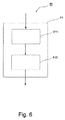
以下に、念のため、図6を参照しながら、少なくとも1つのころ13のための転動軌道を有するころ軸受用の軸受レースを製造する製造方法60について説明する。ころ13は、球状あるいは部分球状に形成されたころ端面21を有し、ころ端面21は、第1の曲率を有している。
In the following, a
製造方法60は、ころ端面21側のつば面32を有する、軸方向力を導出するためにころ端面に向かって配置されたつば31を準備するステップ61を有している。
The
ステップ61自体は、第2の曲率を有する、つば面32の球面状のつば面区分33を準備/形成する第1の下位ステップ611に細分化される。第2の曲率は、第1の曲率に対して、球状に形成されたころ端面21と球面状のつば面区分33との間に第1の間隙寸法d1が得られるように選択される。
第2の下位ステップ612では、ころ端面21と拡開するつば面区分34との間の、第1の間隙寸法d1に対して拡大された間隙寸法d2のために、第2の曲率より小さな曲率を有する、つば面32の拡開するつば面区分34も準備あるいは形成される。これについては、上で既に詳説した。
In a
つまり、総括すると、提案したつば形状は、軸受のミスアライメント及び傾斜位置に対するころ対つば接触点22の敏感性を軽減し、それにもかかわらず転動軌道上での転動中のころ13の十分な案内を保証することを課題としている。本発明に係るつばジオメトリは、ころ案内及び低いヘルツ応力を保証し得る球面状のつば面区分33を有している。さらに、提案したつばジオメトリは、ころ端面21とつば面32との間に、純然たる球面状のつばにより生じる間隙寸法より大きな間隙寸法を形成する、少なくとも1つの拡開するつば面区分34を有している。
That is, in summary, the proposed collar configuration reduces the sensitivity of the roller-to-
球面状のつば面区分33は、例えばつば31の下側の領域で(つば縁部/溝縁部に隣接して)使用可能である。この場合、拡開するつば面区分34は、つばの上側の領域に位置している(図2及び図3参照)。また、球面状に形成されたつば面区分33をつば縁部に隣接させず、拡開するつば面区分34a,34bが、球面状のつば面区分33の上下に設けられているようにすることも可能である(図4及び図5参照)。
The spherical
拡開するつば面区分と組み合わされた球面状のつばの本発明に係るころ対つば接触ジオメトリは、以下に述べる有利な特性を有している:
‐球面状のつば面区分33に基づいて、転動中のころ案内は維持されたままである。
‐球面状のつば面区分33に基づく低いヘルツ応力。
‐拡開するつば面区分34は、純然たる球面状のつばと比較して接触楕円の大きさを減じる。これにより、つば縁部と接触楕円の交差は回避される。
‐拡開するつば面区分34に基づいて、ミスアライメントに関する、ころ端面21とつば31との間の接触点22の位置の比較的低い敏感性が生じる。
‐ころ13とつば31との間の所定の接触点22が得られる。
The roller to collar contact geometry according to the invention of a spherical collar combined with an expanding collar surface section has the following advantageous properties:
On the basis of the
A low Hertz stress based on the
-The expanding
A relatively low sensitivity of the position of the
A
提案したころ対つばのジオメトリは、ころ端面とつばとの間の接触点が、理想的なジオメトリでは、球面状のつば面区分に位置するように設計されている。ミスアライメントに対する接触点の敏感性は、球面状のつば面区分内では、純然たる球面状のつばの敏感性と同一である。接触点がミスアライメントに基づいて拡開するつば面区分内に移動すると、敏感性は著しく低下させられている。敏感性の低下は、つば縁部を超える理論的な接触点の「移動」、ひいては高いエッジ応力を阻止することができる。 The proposed roller-to-collar geometry is designed so that the contact point between the roller end face and the collar is, in an ideal geometry, located in a spherical collar section. The sensitivity of the contact point to misalignment is the same as the sensitivity of a purely spherical collar within the spherical collar section. Sensitivity is significantly reduced when the contact point moves into a brim section that expands based on misalignment. The reduced sensitivity can prevent theoretical “point of contact” movement beyond the brim and thus high edge stresses.
拡開するつば面区分の構成に関して、様々な可能性が存在する。1つには、球面状のつば面区分の円弧に接線方向で接続する直線状のつば面区分が可能である。拡開するつば面区分は、球面状のつば面区分の半径より大きな半径によって規定されてもよい。 There are various possibilities for the configuration of the expanding ribbed section. For one thing, a straight collar surface segment can be connected tangentially to the arc of the spherical collar surface segment. The expanding collar surface section may be defined by a radius greater than the radius of the spherical collar surface section.
本発明について、円錐ころ軸受及び円錐ころを備える実施の形態を参照しながら説明したが、実施の形態は、この種の構成に限定されるものではない。原理的は、本発明は、別のころ及びころ軸受、例えば円筒ころ軸受及び球面ころ軸受にも適用可能である。 Although the present invention has been described with reference to the embodiment including the tapered roller bearing and the tapered roller, the embodiment is not limited to this type of configuration. In principle, the invention is also applicable to other rollers and roller bearings, such as cylindrical roller bearings and spherical roller bearings.
10 ころ軸受
11 軸受内レース
12 軸受外レース
13 ころ
14 内側のころ転動軌道
15 外側のころ転動軌道
16 内側の直線
17 外側の直線
18 軸受回転軸線
19 回転点
20 ころ軸線
21 ころ端面
22 接触点
23 球面状のつば
24 つば面半径
30 軸受レースの一部
31 一部において球面状であって、一部において拡開しているつば
32 つば面
33 球面状のつば面区分
34 拡開するつば面区分
35 転動軌道とつば面との間の角隅領域
36 転動軌道とは反対側のつば縁部
37 球面状のつば面区分と拡開するつば面区分との間の境界
38 拡開するつば面区分内に仮想的に延長した球面状のつば面区分における接線平面
39 拡開するつば区分における接線平面
40 純然たる球面状のつばにおけるつば面ジオメトリ
60 製造方法
61 ころ端面側のつば面を備える、軸方向力を導出するためにころ端面に向かって配置されたつばを準備するステップ
611 球面状のつば面区分を準備する下位ステップ
612 拡開するつば面区分を準備する下位ステップ
DESCRIPTION OF
Claims (10)
前記軸受レース(30)は、前記ころ端面側のつば面(32)を有する、軸方向力を導出するために前記ころ端面に向かって配置されたつば(31)を備え、前記つば面(32)は、第2の曲率を有する球面状のつば面区分(33)を有し、
前記第1の曲率と前記第2の曲率とは、前記球状に形成されたころ端面(21)と前記球面状のつば面区分(33)との間に第1の間隙寸法(d1)が得られるように選択されており、かつ
前記つば面(32)はさらに、拡開するつば面区分(34)を有し、該拡開するつば面区分(34)は、前記ころ端面(21)と前記拡開するつば面区分(34)との間の、前記第1の間隙寸法(d1)より大きな間隙寸法(d2)のための、前記第2の曲率より小さな曲率を有している、
ことを特徴とする、軸受レース。 A bearing race (30) for a roller bearing having a rolling track (14; 15) for at least one roller (13), said roller (13) being at least partially having a first curvature. It has a roller end surface (21) formed in a spherical shape,
The bearing race (30) includes a collar (31) having a collar surface (32) on the roller end surface side and arranged toward the roller end surface to derive an axial force, and the collar surface (32). ) Has a spherical collar surface section (33) having a second curvature,
The first curvature and the second curvature are such that the first gap dimension (d 1 ) is between the spherically formed roller end surface (21) and the spherical collar surface section (33). And the collar surface (32) further comprises an expanding collar surface section (34), the expanding collar surface section (34) being the roller end surface (21). Having a curvature smaller than the second curvature for a gap dimension (d 2 ) between the first gap dimension (d 1 ) and the expanding collar surface section (34). Yes,
A bearing race characterized by that.
前記ころ端面(21)側のつば面(32)を有する、軸方向力を導出するために前記ころ端面に向かって配置されるつば(31)を準備するステップ(61)を有し、該つば(31)を準備するステップ(61)は、
前記つば面の球面状のつば面区分(33)を準備するステップ(611)であって、該球面状のつば面区分(33)が、前記球状に形成されたころ端面(21)と前記球面状のつば面区分(33)との間に第1の間隙寸法(d1)が得られるように前記第1の曲率に対して選択された第2の曲率を有するようにするステップ(611)と、
前記つば面の拡開するつば面区分(34)を形成するステップ(612)であって、前記拡開するつば面区分(34)が、前記ころ端面(21)と前記拡開するつば面区分(34)との間の、前記第1の間隙寸法(d1)に対して拡大された間隙寸法(d2)のための、前記第2の曲率より小さな曲率を有するようにするステップ(612)と、
を有することを特徴とする、軸受レースを製造する方法。 A method (60) for producing a bearing race (30) for a roller bearing having a rolling track (14; 15) for at least one roller (13), said roller (13) comprising a first It has a roller end surface (21) formed into a spherical shape having a curvature,
Providing a collar (31) having a collar surface (32) on the roller end surface (21) side, the collar (31) being arranged toward the roller end surface for deriving an axial force; The step (61) of preparing (31)
A step (611) of preparing a spherical collar surface section (33) of the collar surface, wherein the spherical collar surface section (33) comprises the spherically formed roller end surface (21) and the spherical surface. Having a second curvature selected with respect to the first curvature so as to obtain a first gap dimension (d 1 ) with a shaped collar surface section (33) (611) When,
A step (612) of forming a collar surface section (34) for expanding the collar surface, wherein the collar surface section (34) for expanding the roller end surface (21) and the collar surface section for expanding. Having a curvature smaller than the second curvature for a gap dimension (d 2 ) between (34) and an enlarged gap dimension (d 2 ) with respect to the first gap dimension (d 1 ) (612) )When,
A method of manufacturing a bearing race.
Applications Claiming Priority (3)
| Application Number | Priority Date | Filing Date | Title |
|---|---|---|---|
| DE102010062481.0 | 2010-12-06 | ||
| DE102010062481A DE102010062481B3 (en) | 2010-12-06 | 2010-12-06 | Geometry concept for a roller-to-board contact in roller bearings |
| PCT/EP2011/071157 WO2012076353A1 (en) | 2010-12-06 | 2011-11-28 | Geometric concept for a roller-lip contact for rolling bearings |
Publications (1)
| Publication Number | Publication Date |
|---|---|
| JP2013545057A true JP2013545057A (en) | 2013-12-19 |
Family
ID=45020288
Family Applications (1)
| Application Number | Title | Priority Date | Filing Date |
|---|---|---|---|
| JP2013542456A Pending JP2013545057A (en) | 2010-12-06 | 2011-11-28 | Geometry concept for roller-to-collar contact in roller bearings |
Country Status (10)
| Country | Link |
|---|---|
| US (1) | US8899839B2 (en) |
| EP (1) | EP2649332B1 (en) |
| JP (1) | JP2013545057A (en) |
| CN (1) | CN103238000B (en) |
| DE (1) | DE102010062481B3 (en) |
| DK (1) | DK2649332T3 (en) |
| ES (1) | ES2594755T3 (en) |
| IN (1) | IN2013CN05380A (en) |
| RU (1) | RU2013130988A (en) |
| WO (1) | WO2012076353A1 (en) |
Cited By (2)
| Publication number | Priority date | Publication date | Assignee | Title |
|---|---|---|---|---|
| JP2015203487A (en) * | 2014-04-16 | 2015-11-16 | 株式会社ジェイテクト | Bearing ring for roller bearing, roller bearing and power transmission device |
| JP2017187148A (en) * | 2016-04-08 | 2017-10-12 | 日本精工株式会社 | Rolling body for conical roller bearing, and conical roller bearing |
Families Citing this family (6)
| Publication number | Priority date | Publication date | Assignee | Title |
|---|---|---|---|---|
| DE102011076328B4 (en) * | 2011-05-24 | 2013-11-07 | Aktiebolaget Skf | Geometry concept for a board of a roller bearing |
| DE102013225859B4 (en) * | 2013-12-13 | 2019-10-10 | Aktiebolaget Skf | Raceway element and roller bearing with the raceway element |
| JP2015113972A (en) * | 2013-12-16 | 2015-06-22 | 株式会社ジェイテクト | Tapered roller bearing and power transmission device |
| JP6256023B2 (en) * | 2014-01-16 | 2018-01-10 | 株式会社ジェイテクト | Tapered roller bearing and power transmission device |
| WO2018200324A1 (en) | 2017-04-26 | 2018-11-01 | The Timken Company | Non-elliptical contact profile for roller bearing |
| US11002310B2 (en) * | 2019-01-11 | 2021-05-11 | Aktiebolaget Skf | Rolling-element bearing unit and tapered-roller-bearing inner ring |
Citations (6)
| Publication number | Priority date | Publication date | Assignee | Title |
|---|---|---|---|---|
| JPS5489147A (en) * | 1977-12-26 | 1979-07-14 | Koyo Seiko Co Ltd | Conical roller bearing |
| JPH0490721U (en) * | 1990-12-14 | 1992-08-07 | ||
| JPH0575520U (en) * | 1992-03-19 | 1993-10-15 | 光洋精工株式会社 | Tapered roller bearing |
| JPH0587330U (en) * | 1992-04-30 | 1993-11-26 | エヌティエヌ株式会社 | Tapered roller bearing |
| JP2003120687A (en) * | 2001-10-19 | 2003-04-23 | Nsk Ltd | Tapered roller bearing and its machining method |
| JP2007051703A (en) * | 2005-08-18 | 2007-03-01 | Jtekt Corp | Tapered roller bearing and bearing device for transmission using it |
Family Cites Families (11)
| Publication number | Priority date | Publication date | Assignee | Title |
|---|---|---|---|---|
| CH212693A (en) * | 1939-06-23 | 1940-12-15 | Skf Svenska Kullagerfab Ab | Roller bearings. |
| JP2951036B2 (en) * | 1991-04-30 | 1999-09-20 | エヌティエヌ株式会社 | Tapered roller bearing |
| JP2000065066A (en) * | 1998-08-19 | 2000-03-03 | Nippon Seiko Kk | Cylindrical roller bearing |
| JP2001173665A (en) * | 1999-12-20 | 2001-06-26 | Nsk Ltd | Roller bearing |
| JP4029574B2 (en) * | 2001-01-26 | 2008-01-09 | 株式会社ジェイテクト | Tapered roller bearings |
| JP2004353744A (en) * | 2003-05-28 | 2004-12-16 | Nsk Ltd | Roller bearing |
| JP2005003121A (en) * | 2003-06-12 | 2005-01-06 | Nsk Ltd | Cylindrical roller bearing |
| JP4484771B2 (en) * | 2005-06-15 | 2010-06-16 | Ntn株式会社 | Tapered roller bearing design method |
| DE102005061102A1 (en) * | 2005-12-21 | 2007-07-05 | Schaeffler Kg | roller bearing |
| DE102005061103A1 (en) * | 2005-12-21 | 2007-07-05 | Schaeffler Kg | Rolling bearings with improved board geometry |
| DE102008020068A1 (en) * | 2008-04-22 | 2009-10-29 | Schaeffler Kg | Rolling bearings with curved contact surfaces |
-
2010
- 2010-12-06 DE DE102010062481A patent/DE102010062481B3/en active Active
-
2011
- 2011-11-28 ES ES11788459.3T patent/ES2594755T3/en active Active
- 2011-11-28 RU RU2013130988/11A patent/RU2013130988A/en not_active Application Discontinuation
- 2011-11-28 DK DK11788459.3T patent/DK2649332T3/en active
- 2011-11-28 IN IN5380CHN2013 patent/IN2013CN05380A/en unknown
- 2011-11-28 JP JP2013542456A patent/JP2013545057A/en active Pending
- 2011-11-28 CN CN201180058725.0A patent/CN103238000B/en active Active
- 2011-11-28 WO PCT/EP2011/071157 patent/WO2012076353A1/en active Application Filing
- 2011-11-28 EP EP11788459.3A patent/EP2649332B1/en active Active
- 2011-11-28 US US13/991,221 patent/US8899839B2/en active Active
Patent Citations (6)
| Publication number | Priority date | Publication date | Assignee | Title |
|---|---|---|---|---|
| JPS5489147A (en) * | 1977-12-26 | 1979-07-14 | Koyo Seiko Co Ltd | Conical roller bearing |
| JPH0490721U (en) * | 1990-12-14 | 1992-08-07 | ||
| JPH0575520U (en) * | 1992-03-19 | 1993-10-15 | 光洋精工株式会社 | Tapered roller bearing |
| JPH0587330U (en) * | 1992-04-30 | 1993-11-26 | エヌティエヌ株式会社 | Tapered roller bearing |
| JP2003120687A (en) * | 2001-10-19 | 2003-04-23 | Nsk Ltd | Tapered roller bearing and its machining method |
| JP2007051703A (en) * | 2005-08-18 | 2007-03-01 | Jtekt Corp | Tapered roller bearing and bearing device for transmission using it |
Cited By (2)
| Publication number | Priority date | Publication date | Assignee | Title |
|---|---|---|---|---|
| JP2015203487A (en) * | 2014-04-16 | 2015-11-16 | 株式会社ジェイテクト | Bearing ring for roller bearing, roller bearing and power transmission device |
| JP2017187148A (en) * | 2016-04-08 | 2017-10-12 | 日本精工株式会社 | Rolling body for conical roller bearing, and conical roller bearing |
Also Published As
| Publication number | Publication date |
|---|---|
| CN103238000B (en) | 2016-05-18 |
| US20130322805A1 (en) | 2013-12-05 |
| EP2649332B1 (en) | 2016-07-20 |
| DE102010062481B3 (en) | 2011-12-15 |
| IN2013CN05380A (en) | 2015-09-04 |
| CN103238000A (en) | 2013-08-07 |
| EP2649332A1 (en) | 2013-10-16 |
| RU2013130988A (en) | 2015-01-20 |
| DK2649332T3 (en) | 2016-10-31 |
| ES2594755T3 (en) | 2016-12-22 |
| WO2012076353A1 (en) | 2012-06-14 |
| US8899839B2 (en) | 2014-12-02 |
Similar Documents
| Publication | Publication Date | Title |
|---|---|---|
| JP2013545057A (en) | Geometry concept for roller-to-collar contact in roller bearings | |
| US9188160B2 (en) | Configuration for a roller of a roller bearing | |
| DK2715163T3 (en) | GEOMETRY CONCEPT ON EDGE OF A ROLLER BEARING | |
| JPS5913369Y2 (en) | cylindrical roller bearing | |
| JP6492646B2 (en) | Tapered roller bearing | |
| JP2009520936A (en) | Rolling bearing | |
| ES2805005T3 (en) | Angular Contact Self-aligning Bearing of Toroidal Rolling Elements | |
| CN101331333A (en) | Roller bearing | |
| JPS5834686B2 (en) | Spherical roller bearing with skew controllability | |
| US1587184A (en) | Ball bearing | |
| US9845825B2 (en) | Roller bearing with enhanced stress bearing capacity | |
| WO2016080206A1 (en) | Retainer for thrust roller bearing and method for producing said retainer | |
| US20140064650A1 (en) | Bearing arrangement with a back-up bearing, in particular for mountnig a rapidly rotating shaft | |
| US11624402B2 (en) | Non-elliptical contact profile for roller bearing | |
| JP5715001B2 (en) | Radial ball bearings | |
| US9599160B2 (en) | Tapered roller bearing | |
| JP2017187148A (en) | Rolling body for conical roller bearing, and conical roller bearing | |
| JP6781920B1 (en) | bearing | |
| GB2612486A (en) | Self-aligning roller bearing of asymmetric structure | |
| CN110043566B (en) | Rolling bearing and bearing ring thereof | |
| CN113090655A (en) | Axial gas bearing, compressor and air conditioning unit | |
| JP2009168205A (en) | Tilting pad bearing | |
| JP6707896B2 (en) | Constant velocity joint | |
| CN211039387U (en) | Tapered roller bearing with rolling friction of flanges | |
| JP2008169999A (en) | Retainer for radial ball bearing and radial ball bearing |
Legal Events
| Date | Code | Title | Description |
|---|---|---|---|
| A521 | Request for written amendment filed |
Free format text: JAPANESE INTERMEDIATE CODE: A821 Effective date: 20130607 |
|
| A621 | Written request for application examination |
Free format text: JAPANESE INTERMEDIATE CODE: A621 Effective date: 20140717 |
|
| A977 | Report on retrieval |
Free format text: JAPANESE INTERMEDIATE CODE: A971007 Effective date: 20150423 |
|
| A131 | Notification of reasons for refusal |
Free format text: JAPANESE INTERMEDIATE CODE: A131 Effective date: 20150511 |
|
| A521 | Request for written amendment filed |
Free format text: JAPANESE INTERMEDIATE CODE: A523 Effective date: 20150804 |
|
| A02 | Decision of refusal |
Free format text: JAPANESE INTERMEDIATE CODE: A02 Effective date: 20151221 |