JP2013539405A - Print head nozzle evaluation - Google Patents
Print head nozzle evaluation Download PDFInfo
- Publication number
- JP2013539405A JP2013539405A JP2013520285A JP2013520285A JP2013539405A JP 2013539405 A JP2013539405 A JP 2013539405A JP 2013520285 A JP2013520285 A JP 2013520285A JP 2013520285 A JP2013520285 A JP 2013520285A JP 2013539405 A JP2013539405 A JP 2013539405A
- Authority
- JP
- Japan
- Prior art keywords
- nozzles
- test
- test marks
- substrate
- wiper
- Prior art date
- Legal status (The legal status is an assumption and is not a legal conclusion. Google has not performed a legal analysis and makes no representation as to the accuracy of the status listed.)
- Pending
Links
Images


Classifications
-
- B—PERFORMING OPERATIONS; TRANSPORTING
- B41—PRINTING; LINING MACHINES; TYPEWRITERS; STAMPS
- B41J—TYPEWRITERS; SELECTIVE PRINTING MECHANISMS, i.e. MECHANISMS PRINTING OTHERWISE THAN FROM A FORME; CORRECTION OF TYPOGRAPHICAL ERRORS
- B41J2/00—Typewriters or selective printing mechanisms characterised by the printing or marking process for which they are designed
- B41J2/005—Typewriters or selective printing mechanisms characterised by the printing or marking process for which they are designed characterised by bringing liquid or particles selectively into contact with a printing material
- B41J2/01—Ink jet
-
- B—PERFORMING OPERATIONS; TRANSPORTING
- B41—PRINTING; LINING MACHINES; TYPEWRITERS; STAMPS
- B41J—TYPEWRITERS; SELECTIVE PRINTING MECHANISMS, i.e. MECHANISMS PRINTING OTHERWISE THAN FROM A FORME; CORRECTION OF TYPOGRAPHICAL ERRORS
- B41J29/00—Details of, or accessories for, typewriters or selective printing mechanisms not otherwise provided for
- B41J29/38—Drives, motors, controls or automatic cut-off devices for the entire printing mechanism
- B41J29/393—Devices for controlling or analysing the entire machine ; Controlling or analysing mechanical parameters involving printing of test patterns
- B41J2029/3935—Devices for controlling or analysing the entire machine ; Controlling or analysing mechanical parameters involving printing of test patterns by means of printed test patterns
Landscapes
- Coating Apparatus (AREA)
- Application Of Or Painting With Fluid Materials (AREA)
- Ink Jet (AREA)
Abstract
印刷ヘッドの複数のノズルの性能を評価する方法は、基板の表面上に試験マークを印刷するためにノズルの各々を反復して操作する工程であって、そのノズルにより印刷される試験マークの各々は異なる時間に印刷される、工程を含む。ノズルの各々の反復された操作の間、少なくとも一度、試験マークの少なくとも一部が表面から消去される。そのノズルにより印刷された試験マークは、そのノズルの性能を示す特徴について検査される。
【選択図】図2A method of evaluating the performance of a plurality of nozzles of a print head is the step of repeatedly operating each of the nozzles to print test marks on the surface of a substrate, each of the test marks being printed by the nozzles Includes steps that are printed at different times. At least once during each repeated operation of the nozzle, at least a portion of the test mark is erased from the surface. The test marks printed by the nozzle are inspected for features that indicate the performance of the nozzle.
[Selected figure] Figure 2
Description
本発明は印刷システムに関する。より具体的には、本発明は印刷ヘッドのノズルの評価に関する。 The present invention relates to a printing system. More particularly, the invention relates to the evaluation of the nozzles of a print head.
印刷される文字または図形を形成するために基板にインクを堆積するために最初に開発されたインクジェット印刷の技術はさらなる用途に適用されている。一例として、インクジェット印刷技術は半導体基板の表面に金属導体材料を堆積させるのに適用されている。従って、例えば、インクジェット印刷技術は、太陽光発電のための光電池などの半導体ベースの電子デバイス上に電気的接続を堆積させるのに適用され得る。 The techniques of ink jet printing, originally developed to deposit ink on a substrate to form printed characters or graphics, have been applied to further applications. As an example, inkjet printing techniques are applied to deposit metal conductor materials on the surface of a semiconductor substrate. Thus, for example, inkjet printing techniques can be applied to deposit electrical connections on semiconductor-based electronic devices such as photovoltaic cells for photovoltaic generation.
インクジェットプリンタの印刷ヘッドは典型的に多数のノズルを備え、そのノズルを通して印刷液(例えばインク)が分配され得る。ノズルは典型的に一次元または二次元アレイの形態で配置される。ノズルのアレイは典型的に、並べられるノズルの列またはラインを含む。 The print head of an ink jet printer typically comprises a large number of nozzles through which the printing liquid (e.g. ink) can be dispensed. The nozzles are typically arranged in the form of a one or two dimensional array. The array of nozzles typically includes an array or line of nozzles that are aligned.
インクジェット印刷技術の少なくとも一部の適用に関して、アレイのノズルは、アレイの他のノズルと並べられることが考えられ得る。従って、その適用に使用される各ノズルは、その適用に使用される他のノズルにより堆積される印刷液に関して特定の空間関係で印刷液を堆積させることが考えられ得る。そのような適用の一例には、半導体の表面上に導体材料のラインを堆積させることが含まれ得る。導体材料のラインが所望の厚さを有するように、印刷ヘッドと基板との間の相対運動はアレイのノズルの列に平行な方向であり得る。運動の過程の間、列の複数のノズルは、表面上に同期化して導体材料を堆積させ得る。運動に起因して、各ノズルにより堆積される材料は、導体材料の印刷されたラインの形態であり得る。この場合、列(最初を除く)のノズルの各々は、以前のノズルにより堆積された以前に堆積されたラインの上に導体材料のラインまたは層を堆積させることが考えられる。一貫してかつ正確にそのようにできないと、導体材料の堆積されたラインの質が低下し得る。 For at least some applications of inkjet printing technology, it may be conceivable that the nozzles of the array be aligned with the other nozzles of the array. Thus, it can be envisaged that each nozzle used for the application deposits the printing fluid in a specific spatial relationship with respect to the printing fluid deposited by the other nozzles used for the application. One example of such an application may include depositing a line of conductive material on the surface of a semiconductor. The relative movement between the print head and the substrate may be in a direction parallel to the rows of nozzles of the array so that the lines of conductive material have the desired thickness. During the process of movement, the nozzles of the array may be synchronized onto the surface to deposit the conductor material. Due to the movement, the material deposited by each nozzle may be in the form of printed lines of conductive material. In this case, it is contemplated that each of the nozzles in the row (except the first) deposits a line or layer of conductive material over the previously deposited lines deposited by the previous nozzle. Failure to do so consistently and accurately can degrade the quality of deposited lines of conductor material.
本発明の実施形態の目的は、印刷ヘッドが、一貫して並べられるように印刷適用の一部として材料を堆積することを確実にするように印刷ヘッドのノズルの評価を提供することである。 An object of embodiments of the present invention is to provide an evaluation of the nozzles of the print head to ensure that the print head deposits material as part of the printing application so as to be consistently aligned.
本発明の実施形態のさらなる目的は、再利用可能な基板を用いるノズルの評価を提供することである。 A further object of embodiments of the present invention is to provide an evaluation of nozzles using reusable substrates.
本発明の他の目的および利点は、本発明を読み、添付の図面を検討した後、明らかになるだろう。 Other objects and advantages of the present invention will become apparent after reading the present invention and studying the accompanying drawings.
従って、本発明の一部の実施形態によれば、印刷ヘッドの複数のノズルの性能を評価する方法であって、その方法は、基板の表面上に試験マークを印刷するために複数のノズルの各々を反復して操作する工程であって、そのノズルにより印刷される試験マークの各々は異なる時間に印刷される、工程;ノズルの各々を反復して操作する工程の間、少なくとも一度、表面から試験マークの少なくとも一部を消去する工程;およびそのノズルの性能を示す特徴に関して、そのノズルにより印刷された試験マークを検査する工程を含む、方法が提供される。 Thus, according to some embodiments of the present invention, there is provided a method of evaluating the performance of a plurality of nozzles of a print head, the method comprising the steps of: printing a test mark on a surface of a substrate Operating each repeatedly, each of the test marks printed by the nozzles being printed at different times; at least once from the surface during the operating each of the nozzles repeatedly A method is provided, including the steps of erasing at least a portion of the test marks; and inspecting the test marks printed by the nozzles with respect to the features indicative of the performance of the nozzles.
さらに、本発明の一部の実施形態によれば、試験マークを検査する工程は、試験マークの各々の画像を獲得する工程と、獲得した画像を検査する工程とを含む。 Further, according to some embodiments of the present invention, inspecting the test marks includes acquiring an image of each of the test marks and inspecting the acquired images.
さらに、本発明の一部の実施形態によれば、その方法は、評価した性能が所定の基準と一致する場合、印刷適用に使用するように選択される印刷ヘッドのノズルの群に含めるように複数のノズルのうちの1つのノズルを受け入れる工程を含む。 Furthermore, according to some embodiments of the present invention, the method is to be included in the group of nozzles of the print head selected to be used for printing application if the evaluated performance matches the predetermined criteria. Receiving the nozzle of one of the plurality of nozzles.
さらに、本発明の一部の実施形態によれば、試験マークを消去する工程は、表面をワイパーで擦る工程を含む。 Additionally, in accordance with some embodiments of the present invention, erasing the test marks includes wiping the surface with a wiper.
さらに、本発明の一部の実施形態によれば、その方法は、表面をワイパーで擦っている間、ワイパーと表面との間にワイパーホイルを挿入する工程を含む。 Additionally, in accordance with some embodiments of the present invention, the method includes the step of inserting a wiper foil between the wiper and the surface while rubbing the surface with the wiper.
さらに、本発明の一部の実施形態によれば、その方法は、表面を加熱する工程を含む。 Furthermore, according to some embodiments of the present invention, the method comprises the step of heating the surface.
さらに、本発明の一部の実施形態によれば、基板の表面は、ガラスまたはセラミックを含む。 Furthermore, according to some embodiments of the present invention, the surface of the substrate comprises glass or ceramic.
さらに、本発明の一部の実施形態によれば、その特徴は、試験マークの位置または試験マークの厚さを含む。 Further, according to some embodiments of the present invention, the features include the position of the test mark or the thickness of the test mark.
本発明の一部の実施形態によれば、印刷ヘッドの複数のノズルの安定性を評価する方法であって、その方法は、試験マークを印刷するために複数のノズルの各々を反復して操作する工程であって、そのノズルにより印刷される試験マークの各々は異なる時間に印刷される、工程;およびそのノズルの安定性を決定するためにそのノズルにより印刷された試験マークを比較する工程を含む、方法がさらに提供される。 According to some embodiments of the present invention, a method of evaluating the stability of a plurality of nozzles of a print head, the method operating on each of the plurality of nozzles iteratively to print test marks The test marks printed by the nozzles are each printed at different times; comparing the test marks printed by the nozzles to determine the stability of the nozzles; Methods are further provided, including.
さらに、本発明の一部の実施形態によれば、試験マークを比較する工程は、複数のノズルのうちの1つのノズルにより印刷された試験マークの各々の画像を獲得する工程;およびそのノズルの安定性の欠如を示す試験マーク間の相違を検出するために画像を比較する工程を含む。 Further, according to some embodiments of the present invention, comparing the test marks comprises: acquiring an image of each of the test marks printed by one of the plurality of nozzles; Comparing the images to detect differences between test marks indicating a lack of stability.
さらに、本発明の一部の実施形態によれば、その方法は、決定した安定性が所定の基準と一致する場合、印刷適用に使用するように選択される印刷ヘッドのノズルに群に含めるように複数のノズルのうちの1つのノズルを受け入れる工程を含む。 Further, according to some embodiments of the present invention, the method is grouped into nozzles of a print head selected to be used for printing application if the determined stability matches a predetermined criterion. Receiving a nozzle of the plurality of nozzles.
さらに、本発明の一部の実施形態によれば、その方法は、ノズルの各々を反復して操作する工程の間、少なくとも一度、試験マークの少なくとも一部を表面から消去する工程を含む。 Further, according to some embodiments of the present invention, the method includes the step of erasing at least a portion of the test marks from the surface at least once during the step of repeatedly operating each of the nozzles.
さらに、本発明の一部の実施形態によれば、試験マークを比較する工程は、試験マークの位置を比較する工程または試験マークの厚さを比較する工程を含む。 Further, according to some embodiments of the present invention, comparing the test marks includes comparing the positions of the test marks or comparing the thickness of the test marks.
さらに、本発明の一部の実施形態によれば、印刷ヘッドの複数のノズルの性能を評価するシステムが提供され、そのシステムは、複数のノズルの各々により基板表面上に印刷された試験マークの画像を獲得するための画像装置;獲得された画像の特徴を検出するように構成されるプロセッサであって、その特徴はそのノズルの性能を示す、プロセッサ;および基板表面から試験マークを消去するための消去装置を含む。 Further, according to some embodiments of the present invention, there is provided a system for evaluating the performance of a plurality of nozzles of a print head, the system comprising a plurality of test marks printed on a substrate surface by each of the plurality of nozzles. An imaging device for capturing an image; a processor configured to detect features of the captured image, the features indicating the performance of the nozzle, the processor; and for erasing test marks from the substrate surface Including an eraser.
さらに、本発明の一部の実施形態によれば、ワイパーが基板表面を擦る場合、消去装置は、試験マークを消去するためのワイパーを含む。 Further, in accordance with some embodiments of the present invention, the eraser includes a wiper for erasing the test marks if the wiper rubs the substrate surface.
さらに、本発明の一部の実施形態によれば、ワイパーが基板表面を擦る場合、消去装置がワイパーホイルを分配するためのディスペンサーを含み、ワイパーホイルがワイパーと基板表面との間に挿入される。 Furthermore, according to some embodiments of the present invention, when the wiper rubs the substrate surface, the eraser includes a dispenser for dispensing the wiper foil, the wiper foil being inserted between the wiper and the substrate surface .
さらに、本発明の一部の実施形態によれば、ワイパーホイルは紙を含む。 Furthermore, according to some embodiments of the present invention, the wiper foil comprises paper.
さらに、本発明の一部の実施形態によれば、ワイパーは、摩耗材料により少なくとも部分的に囲まれる弾性材料を含む。 Furthermore, according to some embodiments of the present invention, the wiper comprises an elastic material at least partially surrounded by the wear material.
さらに、本発明の一部の実施形態によれば、摩耗材料は合成樹脂繊維を含む。 Further, according to some embodiments of the present invention, the wear material comprises synthetic resin fibers.
さらに、本発明の一部の実施形態によれば、そのシステムは、基板表面を印刷ヘッド、画像装置、および消去装置のうちの1つ以上に運搬するための運搬装置を含む。 Further, according to some embodiments of the present invention, the system includes a carrier for carrying the substrate surface to one or more of a print head, an imaging device, and an eraser.
本発明をより良く理解し、その実際の適用を認識するために、以下の図面が提供され、本明細書以下で参照される。図面は例のみとして与えられ、本発明の範囲を決して限定するものではないことに留意すべきである。同様の構成要素は同様の参照番号により示される。 In order to better understand the invention and to recognize its practical application, the following figures are provided and referred to hereinafter. It should be noted that the drawings are given by way of example only and in no way limit the scope of the present invention. Similar components are indicated by similar reference numerals.
以下の詳細な説明において、本発明の完全な理解を提供するために複数の特定の詳細が記載される。しかしながら、本発明はこれらの特定の詳細を必要とせずに実施されてもよいことは当業者により理解されるだろう。他の例において、本発明を曖昧にしないように、周知の方法、手順、構成要素、モジュール、装置および/または回路の詳細は記載していない。 In the following detailed description, numerous specific details are set forth in order to provide a thorough understanding of the present invention. However, it will be understood by those skilled in the art that the present invention may be practiced without the need for these specific details. In other instances, well-known methods, procedures, components, modules, devices and / or circuits have not been described in detail in order not to obscure the present invention.
本発明の実施形態は、例えば命令、例えばコンピュータ実行可能命令をコードし、含み、または記憶する、メモリ、ディスクドライブ、もしくはUSBフラッシュメモリなどのコンピュータもしくはプロセッサ可読媒体、またはコンピュータもしくはプロセッサ記憶媒体などの物品を含んでもよく、プロセッサまたはコントローラにより実行される場合、それらは本明細書に開示される方法を実施する。 Embodiments of the present invention may be, for example, a computer or processor readable medium, such as a memory, a disk drive, or a USB flash memory, such as a computer, processor readable medium, etc. Articles may be included and, when executed by a processor or controller, they implement the methods disclosed herein.
本発明の実施形態によれば、印刷ヘッドの各ノズルの質が評価される。評価の結果として、ノズルは、印刷適用に使用するために選択されるノズルの群に含まれるように受け入れられてもよい。例えば、ノズルの安定性の評価は、印刷液を基板の表面上に堆積させることによって異なる時点(例えば周期的)に各ノズルにより反復して印刷される試験マークを比較することからなってもよい。異なる時点において単一ノズルにより印刷された試験マークは、そのノズルで印刷された場合の矛盾し、不規則な、または不安定ないずれかの挙動を検出するために、互いに比較され得る。さらに、ヘッドの異なるノズルにより印刷された試験マークが互いに比較されてもよい。ノズルの1つにより印刷された試験マークが、所定の安定性基準(および任意の他の品質基準)と一致することが試験マークの分析により示された場合、そのノズルは、選択されるノズルの群に含まれるように受け入れられてもよい。基準との一致は典型的に、単一のノズルにより印刷されたマークが互いに一致することを示し(例えばノズルが一貫してかつ安定に印刷することを示す)、それらが、他のノズルにより印刷されたマークと一致することを示す(例えば印刷液の適切なアラインメントおよび分配の許容可能な速度を示す)。 According to an embodiment of the present invention, the quality of each nozzle of the print head is evaluated. As a result of the evaluation, the nozzles may be accepted to be included in the group of nozzles selected for use in the printing application. For example, the evaluation of the stability of the nozzles may consist of comparing test marks printed repeatedly by each nozzle at different times (e.g. periodically) by depositing the printing liquid on the surface of the substrate . Test marks printed by a single nozzle at different times can be compared to each other to detect any inconsistent, irregular or unstable behavior when printed with that nozzle. Furthermore, test marks printed by different nozzles of the head may be compared to one another. If the test mark analysis indicates that the test mark printed by one of the nozzles matches the predetermined stability criteria (and any other quality criteria), then that nozzle is of the selected nozzle. It may be accepted to be included in a group. A match to the reference typically indicates that the marks printed by a single nozzle match each other (eg indicating that the nozzles print consistently and stably), they print with the other nozzles Indicate matching with the marked marks (eg indicating an acceptable speed of proper alignment and distribution of the printing fluid).
選択されるノズルの群に含むための基準は、印刷された試験マークにより測定可能なノズルの特性の値を含んでもよい。例えば、印刷ヘッドの他のノズルにより印刷された試験マークから横方向にずれて、または試験マークについての所望の横方向の位置から横方向にずれて一貫して試験マークを印刷するノズルは、選択されるノズルの群に含まれることを拒絶され得る。 The criteria for inclusion in the group of selected nozzles may include values of properties of the nozzles that can be measured by the printed test marks. For example, nozzles that consistently print test marks laterally offset from test marks printed by the other nozzles of the print head, or laterally from the desired lateral position for the test marks are selected It can be rejected to be included in the group of nozzles being
ノズル印刷の安定性の評価は、ノズルの過去の試験の記録した結果(ノズル性能の履歴とも称される場合がある)との比較を含んでもよい。評価は、異なる時点で実施された試験に対する様々な重要性または関連性を割り当てる重み付け計数を含んでもよい。例えば、最近実施した試験の結果が、最近実施していない以前の試験の結果より重要であると割り当てられてもよい。 The evaluation of the stability of the nozzle printing may comprise a comparison with the recorded results of a past test of the nozzle (which may also be referred to as the history of the nozzle performance). The assessment may include weighted counts that assign various significance or relevance to tests performed at different times. For example, the results of a recently performed test may be assigned more important than the results of previous tests that have not been recently performed.
典型的に、試験マークの評価は、画像装置(例えばカメラ、ビデオカメラ、またはスキャナ)により試験マークの画像を獲得し、分析することを含む。安定性の不足は、異なる時点において単一ノズルにより印刷された試験マークの画像間の相違により示されてもよい。 Typically, evaluation of a test mark involves acquiring and analyzing an image of the test mark with an imaging device (e.g. a camera, video camera or scanner). The lack of stability may be indicated by differences between images of test marks printed by a single nozzle at different times.
本発明の実施形態によれば、ノズルの評価は再利用可能な基板上に試験マークを印刷することを含んでもよい。試験マークは、基板の再利用前に、(試験マークの任意の種類の除去を参照して理解するために)除去または消去されてもよい。例えば、試験マークは、試験マークの検査または画像化後に消去されてもよい。あるいは、基板の表面が、以前に印刷されたマークで覆われた場合、さらなる印刷を防ぐかまたは困難にし、試験マークを識別可能にする程度まで試験マークは消去されてもよい。あるいは、試験マークは、周期的にまたは所定の基準に従って消去されてもよい。 According to embodiments of the present invention, evaluation of the nozzles may include printing test marks on the reusable substrate. The test marks may be removed or erased (for understanding with reference to the removal of any kind of test marks) before recycling the substrate. For example, test marks may be erased after inspection or imaging of the test marks. Alternatively, if the surface of the substrate is covered with previously printed marks, the test marks may be erased to the extent that prevents further printing or makes it difficult and makes the test marks identifiable. Alternatively, the test marks may be erased periodically or according to predetermined criteria.
本発明の実施形態に係るノズル評価は、プリンタまたは印刷システムが、印刷ヘッドの複数のノズルの中からノズルの1つ以上の群を選択できるようにし得る。選択は、基板上への反復印刷および試験マークのパターンの自動検査の結果として実施されてもよい。自動検査は、ノズルの1つ以上の群を識別でき、その群の中で、ノズルの群は、互いに並べられ、(例えば、各マークを形成するために堆積した印刷液の量に関して)互いに類似しているマークを一貫して印刷する。1つ以上の識別されたノズルの群は、印刷操作の間、使用のために選択されてもよい。印刷操作の間、ノズルの選択された群は、基板上に協働して印刷液(例えばインクまたは金属導体材料)を堆積させるように作動されてもよい。 Nozzle evaluation according to embodiments of the present invention may allow the printer or printing system to select one or more groups of nozzles from among the plurality of nozzles of the print head. Selection may be performed as a result of repeated printing on the substrate and automatic inspection of the pattern of test marks. Automatic inspection can identify one or more groups of nozzles, in which groups of nozzles are aligned with one another and similar to one another (e.g., with respect to the amount of printing fluid deposited to form each mark) Print consistent marks. A group of one or more identified nozzles may be selected for use during the printing operation. During a printing operation, selected groups of nozzles may be actuated to cooperate to deposit printing fluid (eg, ink or metal conductor material) on the substrate.
例えば、本発明の一実施形態に係るノズル安定性評価の結果、印刷ヘッド(例えば、ノズル間に約70μmの分離距離を有する256個のノズルを含む)のノズルの列からノズルの群(例えば10個のノズル)の選択が得られ得る。選択された群のノズルは、単一の直線に沿って反復可能な量の導体材料を基板上に一貫して堆積できると識別される。このような選択された群の印刷適用は、典型的に、基板上の印刷ヘッドの単一通過の間、導体材料の単一の多層ラインを半導体基板上に堆積させるように選択された群のノズルの操作を含んでもよい。 For example, as a result of nozzle stability evaluation according to an embodiment of the present invention, a group of nozzles (e.g. 10) from a row of nozzles of a print head (e.g. comprising 256 nozzles with a separation distance of about 70 [mu] m between nozzles) A choice of nozzles can be obtained. The selected group of nozzles is identified as being able to consistently deposit repeatable amounts of conductive material on a substrate along a single straight line. Such a selected group of printing applications is typically selected to deposit a single multilayer line of conductive material on a semiconductor substrate during a single pass of the print head over the substrate. The operation of the nozzle may be included.
例えば、印刷装置は、(例えば印刷ヘッド、基板またはその両方の直線運動により)印刷ヘッドと基板との間に直線相対運動を生じてもよい。典型的に、直線運動はノズルの列に平行な方向である。直線相対運動の間、基板の表面上の特定の位置が、選択された群のノズルの各々の反対側に連続して見出され得る。選択された群のノズルの全てまたは一部は、各ノズルが、そのノズルと現在反対側にある基板表面上の位置において導体材料を堆積させるように、同時にまたは連続して(または異なる時点でその両方で)作動されてもよい。従って、選択された群の第1のノズルが基板上の特定の位置に導体材料を堆積させた後、続いて第2のノズルが、第1のノズルにより堆積された導体材料の上部に、より多くの導体材料を堆積させる。従って、導体材料の第2の層が第1の層の上に堆積される。従って、印刷適用の間に作動するノズルの数は、各々の印刷されたライン上に堆積される導体材料の層の数(例えば10)を超えない。 For example, the printing device may produce a linear relative movement between the print head and the substrate (e.g., by linear movement of the print head, the substrate or both). Typically, linear motion is in a direction parallel to the row of nozzles. During linear relative movement, specific positions on the surface of the substrate can be found successively on opposite sides of each of the selected group of nozzles. All or part of the selected group of nozzles simultaneously or sequentially (or at different times) so that each nozzle deposits conductive material at a position on the substrate surface that is currently opposite the nozzle Both) may be operated. Thus, after a selected group of first nozzles has deposited conductive material at specific locations on the substrate, a second nozzle is subsequently placed on top of the conductive material deposited by the first nozzles. Deposit a lot of conductor material. Thus, a second layer of conductive material is deposited on the first layer. Thus, the number of nozzles activated during the printing application does not exceed the number of layers of conductive material (e.g. 10) deposited on each printed line.
典型的に、各々の堆積された層は、後の層の堆積前に凝固され得るので、ノズルの適切なアラインメントにより、多層ラインの幅が、単一層の幅とほぼ等しくなることが確保され得る。この例において特に、不必要にラインの幅を拡大しないように、ノズルジェットの方向性(インクが分配される横方向)が特に重要であり得る。この場合、特に、各ノズルは、以前に堆積された層の上部に可能な限り近接してその層を堆積すべきである。 Typically, because each deposited layer can be solidified prior to the deposition of later layers, proper alignment of the nozzles can ensure that the width of the multilayer line is approximately equal to the width of a single layer . Especially in this example, the directionality of the nozzle jet (the lateral direction in which the ink is dispensed) may be particularly important so as not to unnecessarily expand the width of the line. In this case, in particular, each nozzle should deposit that layer as close as possible to the top of the previously deposited layer.
印刷ヘッドのノズルの評価は、印刷ヘッドの各ノズル、または印刷ヘッドのノズルのサブセット(例えばノズルのアレイの単一の列)の各ノズルが、所定の順序で試験基板に印刷するように作動する、印刷操作を実施することを含む。例えば、印刷ヘッドと基板との間の直線相対運動の間、各ノズルは連続して、細長い線部分(または破線)の形態で試験マークを印刷してもよい。次いで、画像システムが、印刷された試験マークのパターンの画像(複数も含む)を獲得してもよい。マークの分析は、性能が他のノズルの性能から著しく外れる、それらのノズルを識別できる。このような外れることは、他のノズルにより印刷された試験マークの位置に対して横方向または縦方向にずれた試験マーク(例えば、他のノズルから異なって向けられるノズルを示す)、あるいは他の試験マークより厚いかまたは薄い試験マーク(例えば、他のノズルの分配速度と異なる速度で材料を分配するノズルを示す)の印刷を含んでもよい。獲得された画像は、その後の試験結果との後での比較のために保存されてもよい。 The evaluation of the nozzles of the print head operates such that each nozzle of the print head or each nozzle of a subset of nozzles of the print head (e.g. a single row of an array of nozzles) prints on the test substrate in a predetermined sequence , Including performing a printing operation. For example, during linear relative movement between the print head and the substrate, each nozzle may print test marks in the form of elongated line segments (or dashed lines) in succession. The imaging system may then obtain an image (s) of the printed test mark pattern. Analysis of the marks can identify those nozzles whose performance deviates significantly from the performance of the other nozzles. Such deviations may be due to test marks (e.g., indicating nozzles that are directed differently from other nozzles) or other test marks that are laterally or longitudinally offset with respect to the position of test marks printed by the other nozzles. Printing of test marks that are thicker or thinner than the test marks (e.g. indicating a nozzle that dispenses material at a rate different from that of the other nozzles) may be included. The acquired images may be saved for later comparison with subsequent test results.
印刷操作は所定の間隔で反復されてもよい。例えば、試験マークのパターンは、同じ基板表面上、または異なる基板表面上の別の位置において後の時間に印刷されてもよい。別の例として、試験マークは、基板表面から消去されてもよいか、またはそうでなければ除去されてもよい。次いで別のセットの試験マークが試験基板上の同じ位置に印刷されてもよい。次いで後に印刷された試験マークのパターンの画像が獲得され、分析されてもよい。後に獲得された試験画像の分析は、以前に獲得された試験画像の保存された結果と新たに獲得された結果との比較を含んでもよい。ノズルの1つにより印刷された試験マークの出現の画像間の有意な変化は、ノズルが、可変の一貫性のない不安定なまたは不規則な挙動で印刷することを示し得る。 The printing operation may be repeated at predetermined intervals. For example, the pattern of test marks may be printed at a later time on the same substrate surface or at different locations on different substrate surfaces. As another example, the test marks may be erased or otherwise removed from the substrate surface. Another set of test marks may then be printed at the same location on the test substrate. An image of the pattern of test marks printed later may then be acquired and analyzed. The analysis of test images acquired later may include comparison of the stored results of previously acquired test images with the newly acquired results. A significant change between images of the appearance of test marks printed by one of the nozzles may indicate that the nozzles print with variable inconsistencies, unstable or irregular behavior.
典型的には、適用に必要とされるノズルの数(例えば上述の例のように10)が、ノズルの選択される群に含むように選択されてもよい。選択される群についてのノズルは、(試験パターンの画像の分析により示される)挙動が所定の基準を満たす、それらのノズルの中から選択されてもよい。その基準は、時間にわたる一貫性ならびにマークの位置および質が規定の制限の範囲内にあることを含んでもよい。 Typically, the number of nozzles required for the application (e.g. 10 as in the example above) may be selected to be included in the selected group of nozzles. The nozzles for the selected group may be selected among those nozzles whose behavior (as indicated by analysis of the image of the test pattern) meets predetermined criteria. The criteria may include consistency over time and that the position and quality of the mark is within defined limits.
所定の基準を満たす受容可能なノズルの数は、必要とされるノズルの数より多くてもよい。受容可能なノズルの数が必要とされるノズルの数より多い場合、群について選択されるノズルは、ノズル試験の間に最適に実施されるそれらのノズルであってもよい。例えば、スコアが各ノズルに割り当てられてもよい。スコアは、そのノズルにより印刷された試験マークの分析に基づいてもよい。スコアは、特定の印刷適用に対するマークの様々な特性の相対的重要性(例えば予想される位置に対する位置、印刷されたマークの薄さまたは厚さ、一貫性などの特性)に基づいた式に基づいて計算されてもよい。あるいは、群に含まれるノズルは、それらの間隔またはノズル性能試験の間のノズルの性能に関連しない他の基準に基づいた受容可能なノズルの中から選択されてもよい。あるいは、ノズルは、群に含まれる受容可能のノズルの中からランダムに選択されてもよい。あるいは、ノズルは、群に含まれる受容可能なノズルの中から順番で選択されてもよい(例えば、1セットのノズルが、1つの印刷ジョブの間の操作のために選択され、第1のセットと部分的に重なってもよい異なるセットが、異なる印刷ジョブのために選択されてもよい)。 The number of acceptable nozzles meeting the predetermined criteria may be greater than the number of required nozzles. If the number of acceptable nozzles is greater than the required number of nozzles, the nozzles selected for the group may be those nozzles that are optimally performed during the nozzle test. For example, a score may be assigned to each nozzle. The score may be based on an analysis of test marks printed by the nozzle. The score is based on an expression based on the relative importance of the various properties of the mark to the particular printing application (eg properties such as position relative to expected position, thickness or thickness of the printed mark, consistency etc.) May be calculated. Alternatively, the nozzles included in the group may be selected from among the acceptable nozzles based on their spacing or other criteria not related to the performance of the nozzles during the nozzle performance test. Alternatively, the nozzles may be randomly selected among the acceptable nozzles included in the group. Alternatively, the nozzles may be selected in order from among the acceptable nozzles included in the group (e.g., one set of nozzles is selected for operation during one print job, the first set And different sets, which may partially overlap, may be selected for different print jobs).
受容可能なノズルの数が、必要とされるノズルの数より少ない場合、印刷ヘッドは、1つまたは複数の適用には不適格であり得る。あるいは、例えば、厳格な要求を必要としない適用に関して、要求は、必要とされる数のノズルを群に含むように緩和されてもよい。 If the number of acceptable nozzles is less than the number of required nozzles, the print head may be ineligible for one or more applications. Alternatively, for example, for applications that do not require stringent requirements, the requirements may be relaxed to include the required number of nozzles in a group.
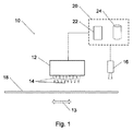
図1は、本発明の一実施形態に係る、印刷ヘッドノズル安定性評価のためのシステムの概略図である。印刷ヘッドノズル安定性評価システム10は、印刷ヘッド12と、画像装置16と、制御装置20とを備える。
FIG. 1 is a schematic view of a system for printhead nozzle stability assessment, according to one embodiment of the present invention. The print head nozzle
印刷ヘッド12は、印刷液(例えばインクまたは導体材料)を分配するためのノズル14を備える。分配された印刷液は基板18上に堆積され得る。印刷ヘッド12が基板18上に印刷液を堆積している間、基板18および印刷ヘッド12は互いに対して移動する。典型的には、基板18は印刷ヘッド12を超えて移動されてもよい。
The
印刷ヘッド12のノズル14は基板18上に試験マークを印刷するように印刷液を堆積させる。印刷は、ノズル14の1つにより堆積される印刷液が、別のノズルにより堆積される印刷液と識別できるように構成される。例えば、ノズルの列の各ノズル14は一度に操作されてもよい。基板18が印刷ヘッド12に対して移動すると、各ノズル14は試験マークを基板18上に連続して堆積させる。従って、一連の試験マークが基板18上に印刷され得る。ノズル14が作動する順序が既知である場合、各試験マークを印刷するノズル14は、そのシリーズ内の試験マークの位置により決定されてもよい。例えば、マークは、そのシリーズの1つの終わりにおいて既知の参照試験マークから続けてカウントされてもよい。あるいはまたはさらに、基板18は、1つまたは複数の基準マークまたはラインでマークされてもよい。各試験マークは、基準マークに対する既知の位置(名目上、ノズル14の印刷挙動に依存する)において基板18上に印刷されてもよい。
The
図2は、本発明の一実施形態に従う、印刷ヘッドノズル安定性評価のための試験マークの堆積を概略的に示す。 FIG. 2 schematically illustrates the deposition of test marks for print head nozzle stability assessment, in accordance with one embodiment of the present invention.
印刷ヘッド12のノズル14は列15の形態で配置される。列15の各ノズル14は、順に、試験マーク26を基板18上に堆積させる。特定のノズル14により基板18上に印刷された特定のマーク26の例は線17により示される。例えば、基板18は、ガラス、セラミック、または半導体材料の表面を備えてもよい。基板18上の試験マーク26の印刷の間、基板18は、印刷ヘッド12に対して矢印25により示された方向において、(単一の方向および一定の速度において)直線的に移動される。矢印25により示された方向は、列15の方向と実質的に平行である。直線相対運動は、基板18、印刷ヘッド12、またはその両方の直線運動により実現され得る。相対的直線運動に起因して、各マーク26が、細長いマークの形態(例えば破線またはハイフンの形態)で基板18上に印刷されてもよい。
The
例えば、列15に配置される256個のノズル14を含む印刷ヘッド12において、256個の試験マーク26が、名目上の線形配置において基板18上に印刷され得る。例えば、基板18が約150mm長である場合、試験マーク26の各々は、ミリメートル長のおよそ半分より長くなくてもよい。
For example, in a
基板18は、さらなるセットの試験マーク26で、さらに1回または複数回マークされてもよい。例えば、制御装置20は、2回以上、互いに基板18および印刷ヘッド12を移動させるように構成されてもよい。例えば、基板輸送装置またはシステムは、さらなるセットの試験マーク26を印刷するために基板18を印刷ヘッド12に戻すように構成されてもよい。さらなるセットの試験マーク26は、定期的に所定の間隔(例えば1分に1回)、ランダムな間隔、または印刷ヘッドノズル安定性評価システム10の人の操作により示されるように自動的に印刷されてもよい。例えば、さらなるセットの試験マーク26を印刷するために、基板18が印刷ヘッド12に戻る時間ごとに、基板18は、横方向に変位されてもよいか、またはそうでなければさらなるセットの試験マーク26が、試験マーク26の以前のセットである基板18の表面の異なる部分に印刷される。従って、試験マーク26の各セットは、以前に印刷されたセットから識別可能であり得る。
The
基板18は、基準線27などの1つ以上の基準マーク(または基準マークのセット)でマークされてもよい。基準線27は、試験マーク26を堆積または評価するための空間的基準を提供してもよい。
The
図1を再び参照すると、試験マークで印刷した後に、基板18は、基板輸送装置13により画像装置16まで輸送または運搬されてもよい。両方向矢印により概略的に示されている、基板輸送装置13は、当該技術分野において公知の1つ以上の基板運搬装置、またはそのような装置の組み合わせもしくはシリーズを表し得る。そのような運搬装置としては、例えば、コンベヤベルト、ロボットアーム、流体(液体または気体)ベースの流れ基板運搬シスステム、または移動プラットフォームが挙げられ得る。
Referring again to FIG. 1, after printing with the test marks, the
画像装置16は、1つ以上のビデオまたはさらにカメラ、スキャナ、または基板18上の試験マーク26の画像を獲得できる任意の他の装置を備えてもよい。画像装置16のコンポーネント装置は、異なるスペクトル領域に敏感な画像装置を備えてもよい。基板18が画像装置16に運搬される場合、画像装置16は、基板18上の試験マークの1つ以上の画像を獲得するように操作されてもよい。画像装置16の解像度は、互いから個々の試験マーク26を識別し、その関連したノズル14の選択に関係し得る試験マーク26の任意の特徴を分解するのに十分であり得る。
The
複数のセットの試験マークが基板18上に印刷される事象において、各セットの試験マークの印刷後、および別のセットの印刷前に、基板18は画像装置16に輸送されてもよい。あるいは、2つ以上のセットの試験マークが基板18に印刷された後にのみ、基板18は画像装置に輸送されてもよい。
In the event that multiple sets of test marks are printed on the
制御装置20はプロセッサ22およびデータ記憶装置24を含む。制御装置20は2つ以上の別の装置を表してもよい。別の装置は、関連または重複する機能を実施してもよいか、あるいは互いに独立してもよい。制御装置20は、印刷ヘッドノズル安定性評価システム10に関連または一体化されている印刷ヘッド12、画像装置16、および任意の他の装置もしくはシステム(例えばコンベヤまたは輸送装置)からのデータまたは信号と通信してもよく、それらの操作を制御してもよい。
プロセッサ22は1つ以上の処理装置を表してもよい。処理装置は、印刷ヘッドノズル安定性評価システム10、印刷ヘッド12(またはプロセッサがコンポーネントであるプリンタもしくは印刷装置)、または画像装置16と通信するコンピュータと関連付けられてもよい。プロセッサ22は、印刷ヘッド12および画像装置16の操作を制御するための命令を作成してもよい。プロセッサ22は、画像装置16により獲得される画像データを分析するように構成されてもよい。例えば、プロセッサ22は、異なる時点で印刷された試験マーク26の画像を比較するように構成されてもよい。
データ記憶装置24は、集合的に、1つ以上の揮発性または不揮発性、固定または除去可能なデータ記憶またはメモリ装置を表してもよい。データ記憶装置は、印刷ヘッド12および画像装置16の操作を制御するため、画像装置16により獲得される画像または他のデータを分析するためのプログラム命令を記憶するように構成されてもよい。データ記憶装置は、画像装置16により獲得される画像データを記憶するように構成されてもよい。
画像装置1により獲得される画像データは、制御装置20のプロセッサ22により分析されてもよい。分析の結果として、ノズル14の一部が、選択されるノズルの群に含めるように選択されてもよい。例えば、分析は、獲得された画像の残りから印刷された試験マークの画像を識別すること、各試験マークを少なくとも部分的に特徴付ける特性値(例えば、位置、方向、長さ、幅または厚さ、均一性)を計算することを含んでもよい。複数のセットの試験マークが単一のウェハに印刷される事象において、分析はまた、試験マークのセットを互いから識別することを含んでもよい。試験マークの各画像は、時間にわたる特性値の一貫性または安定性を決定するために、以前にまたは後に印刷される試験マークの画像と比較されてもよい。
The image data acquired by the
選択されるノズルの群の選択後、制御装置20または別の印刷制御装置が、基板上のパターンを堆積または印刷するために印刷ヘッド12を操作してもよい。制御装置は、所望のパターンを堆積させるように印刷液を分配するためにノズル14の操作を制御する。選択の結果として、制御装置は、印刷液を分配することを、選択されるノズルの群に含んだそれらのノズルに制限してもよい。
After selection of the selected group of nozzles,
図3は、本発明の一実施形態に係る、印刷ヘッドノズル安定性評価基準を概略的に示す。 FIG. 3 schematically illustrates print head nozzle stability metrics according to one embodiment of the present invention.
試験マーク26は、印刷ヘッドと基板との間の直線運動の間に、印刷ヘッドのノズルにより印刷されたマークの画像を表す。試験マーク26’は、同じ印刷ヘッドの同じノズルにより、同じようにではあるが、別の時間に印刷されたマークの画像を表す。例えば、試験マーク26は基板上の1つの位置で印刷されてもよく、一方、試験マーク26’は、例えば図3に示すように、同じ基板上の横方向に変位した位置で印刷された。あるいは、試験マーク26および26’は、図3に示すように、別々に印刷された2セットのマークの例示目的のために並列で表してもよい。例えば、試験マーク26’は、直線的にまたはそうでなければ試験マーク26が印刷された同じ基板上、または試験マーク26が基板から消去されるかまたはそうでなければ除去された後、別の基板上もしくは同じ基板上の移動させた位置に印刷されてもよい。 The test marks 26 represent an image of the marks printed by the nozzles of the print head during linear motion between the print head and the substrate. The test marks 26 'represent the image of the marks printed by the same nozzle of the same print head, but in a similar but different time. For example, test marks 26 may be printed at one location on the substrate while test marks 26 'are printed at laterally displaced locations on the same substrate, as shown for example in FIG. Alternatively, test marks 26 and 26 'may be represented in parallel for the purpose of illustration of two sets of marks printed separately, as shown in FIG. For example, the test marks 26 'may be linearly or otherwise on the same substrate on which the test marks 26 are printed, or another after the test marks 26 have been erased or otherwise removed from the substrate. It may be printed at a moved position on the substrate or on the same substrate.
試験マーク26および26’は分析されてもよい。分析により、特定の試験マーク26を印刷したノズルおよびその対応する試験マーク26’が選択されたノズルの群に含まれるか否かが示され得る。
Test marks 26 and 26 'may be analyzed. The analysis may indicate whether a
試験マーク26および26’の分析は典型的に、試験マーク26および26’の相対位置の分析を含む。ライン28は、試験マーク26の名目上の位置および方向を表す代表的な仮想ラインである。例えば、ライン28は、試験マーク26に対する直線の線形フィット(例えば少なくとも正方形または他のフィット)を表してもよい。同様に、ライン28’は、試験マーク26’の名目上の位置および方向を表す。
Analysis of test marks 26 and 26 'typically involves analysis of the relative position of test marks 26 and 26'.
あるいは、ライン28および28’は、基板表面上に提供(例えばエッチング)される基準線または基準線に対する位置を表してもよい。例えば、試験マーク26および26’は基板の細長い領域内に印刷されてもよい。細長い領域は、平行線(例えば図2における基準線27)により基板表面上に画定されてもよい。試験マーク26および26’は、名目上、画定しているラインの間の真ん中にある仮想中心線に沿って印刷される(中心ラインは典型的に、試験マーク26または26’の検出および分析を邪魔しないように実際には目に見えない)。この場合、ライン28および28’は、細長い領域の仮想中心線を表してもよい。
Alternatively,
試験マーク26とライン28の1つの間の横方向距離が所定の横方向距離を超える場合、または試験マーク26’とライン28’の1つの間の横方向距離が所定の横方向距離を超える場合、マークを印刷したノズルが、他の列のノズルのように同じ相対的横方向において印刷液を一貫して分配しないことが示され得る。次いで関連したノズルが、選択されるノズルの群内に含まれる選択から排除されてもよい。
When the lateral distance between the
例えば、範囲外の試験マーク26aは、それぞれ試験マーク26および試験マーク26’の他のものより線28および線28’からのより長い横方向の距離として示される。
For example, out of
試験マーク26および26’の分析は、試験マーク26および26’のサイズまたは視認性の分析を含んでもよい。試験マーク26または26’の出現(例えば幅または厚さ、あるいは画像バックグラウンドに対するマークの画像の相対的色または階調レベルにより特徴付けられる光学的重み)は他の試験マーク26または26’の出現とは異なってもよい。例えば、ノズル選択システムに関連する画像装置が、試験マーク26または26’の幅を分解するために十分な解像度を有する場合、幅(例えば幅の平均または他の特性値)が、試験マーク26または26’の出現を特徴付けるために使用されてもよい。あるいはまたはさらに、試験マーク26または26’の出現は、試験マーク26または26’の光学的重みにより特徴付けられてもよい。このような出現の相違により、異なって出現するマークを有するノズルは、列の他のノズルと同じ速度でインクを一貫して分配しないことが示され得る。従って、その関連したノズルは、選択されるノズルの群に含まれることから除外されてもよい。
Analysis of test marks 26 and 26 'may include analysis of the size or visibility of test marks 26 and 26'. The appearance of the test marks 26 or 26 '(for example the width or thickness, or the optical weight characterized by the relative color or tone level of the image of the mark relative to the image background) is the appearance of the other test marks 26 or 26' It may be different from For example, if the imaging device associated with the nozzle selection system has sufficient resolution to resolve the width of the
例えば、目に見えない試験マーク26bは完全に消失して示される。これにより、対応するノズルが印刷液を全く分配しない(または非常に弱く分配する)ことが示され得る。濃い試験マーク26cは試験マーク26および26’の他のものより厚く示される。これにより、対応するノズルが、列の他のノズルより速い速度で印刷液を分配することが示され得る。薄い試験マーク26dは、試験マーク26および26’の他のものより薄く示される。これにより、対応するノズルが、列の他のノズル低い速度で印刷液を分配することが示され得る。従って、目に見えない試験マーク26b、濃い試験マーク26c、または薄い試験マーク26dのいずれかに対応するノズルは、選択されるノズルの群に含めることから除外されてもよい。
For example, the invisible test marks 26b are shown completely disappearing. This may indicate that the corresponding nozzle dispenses no printing fluid (or dispenses very weakly). The
試験マーク26および26’の分析は、同じノズルにより印刷された試験マーク26と試験マーク26’との間の位置または出現の変化の分析を含んでもよい。試験マーク26の出現(例えば厚さまたは重み)または位置が、その対応する試験マーク26’のものと異なる場合、関連するノズルが、安定または一貫した方式で作動することが示され得る。例えば、ノズルが、不安定または可変速度で印刷液を分配すること、あるいはノズルが、不安定または可変の方向において印刷液を分配することが示され得る。従って、関連するノズルは、選択されるノズルの群に含めることから除外されてもよい。
The analysis of the test marks 26 and 26 'may comprise an analysis of the change in position or appearance between the test marks 26 printed by the same nozzle and the test marks 26'. If the appearance (e.g. thickness or weight) or position of
例えば、第1の試験マーク26eの出現は、対応する第2の試験マーク26e’の出現とは異なる(重みがある(濃い))。これにより、第1の試験マーク26eおよび第2の試験マーク26e’を印刷したノズルが、印刷の間に堆積される印刷液の質(または堆積速度)に関して不安定であることが示され得る。従って、そのノズルは、選択されるノズルの群に含めることから除外されてもよい。
For example, the appearance of the
別の例として、ライン28に対する第1の試験マーク26fの横方向の位置は、ライン28’に対する対応する試験マーク26f’の横方向の位置とは異なる(反対かつ大きい)。相対的な横方向の位置のこの相違により、第1の試験マーク26fおよび第2の試験マーク26f’を印刷したノズルは、印刷の間に印刷液が分配される横方向に関して不安定であることが示され得る。従って、そのノズルは、選択されるノズルの群に含めることから除外されてもよい。
As another example, the lateral position of the first test mark 26f with respect to the
試験マーク26および26’が印刷される表面上の試験基板は、試験マーク26および26’の印刷および分析を容易にするように選択されてもよい。従って、試験基板は、例えば、ダミー(例えば回路を含まない)シリコンウェハ、ガラスまたはセラミックウェハまたはスライド、あるいは紙またはボール紙の適切に成形された部分を含んでもよい。さらなる考慮により、試験基板の選択にさらに影響を与えることができる。例えば、使い捨ての様式(例えば、表面を印刷した試験マークで満たした後にダミーシリコンウェハを捨てる)でダミーシリコンウェハを用いることは、他の代替法より高価になり得る。しかしながら、印刷システムが設計される基板(例えばシリコンウェハ)と、その特性(例えば密度、厚さまたは質量)が異なる安価な使い捨て試験基板(例えば紙またはボール紙)の使用は、配置または操作に関する問題を引き起こす場合がある。本発明の一実施形態に係る1つの解決策は、関連特性(例えば寸法および質量)が、システムが設計される基板(例えばシリコンウェハ)のものと同様である再利用可能な試験基板(例えばガラスまたはセラミック表面を有する)を提供することである。 The test substrate on the surface on which test marks 26 and 26 'are printed may be selected to facilitate printing and analysis of test marks 26 and 26'. Thus, the test substrate may comprise, for example, a dummy (e.g. circuit free) silicon wafer, a glass or ceramic wafer or slide, or a suitably shaped portion of paper or cardboard. Additional considerations can further influence the choice of test substrate. For example, using a dummy silicon wafer in a disposable manner (e.g. discarding the dummy silicon wafer after filling the surface with test marks printed) may be more expensive than other alternatives. However, the use of a substrate (e.g. a silicon wafer) on which the printing system is designed and an inexpensive disposable test substrate (e.g. paper or cardboard) which differs in its properties (e.g. density, thickness or mass) is a problem with placement or operation May cause. One solution according to an embodiment of the present invention is a reusable test substrate (e.g. glass) whose relevant properties (e.g. size and mass) are similar to those of the substrate (e.g. silicon wafer) on which the system is designed Or providing a ceramic surface).
本発明の一実施形態に係るノズル選択は、再利用可能な基板上に印刷液を堆積させることを含んでもよい。ノズル選択設定またはシステムは、再利用前に基板から堆積された印刷液を消去またはそうでなければ除去するための装置を含んでもよい。 Nozzle selection according to an embodiment of the present invention may include depositing the printing fluid on a reusable substrate. The nozzle selection settings or system may include an apparatus for erasing or otherwise removing the printing fluid deposited from the substrate prior to reuse.
図4Aは、本発明の一実施形態に係る、再利用可能な基板を使用する印刷ヘッドノズル安定性評価を概略的に示す。 FIG. 4A schematically illustrates printhead nozzle stability assessment using a reusable substrate, according to one embodiment of the present invention.
再利用可能な基板を用いるノズル選択のシステムは、マーク消去装置30を有する印刷ヘッドノズル安定性評価システム10を含んでもよい。再利用可能な基板19(例えば平坦なガラスまたはセラミックプレート)は印刷ヘッド12に輸送または運搬されてもよい。印刷ヘッド12は再利用可能な基板19上に試験マーク26のセットを堆積させてもよい。
The system of nozzle selection using reusable substrates may include a printhead nozzle
試験マーク26のさらなるセットが、後の時間に再利用可能な基板19上に印刷されてもよい。試験マーク26の1つ以上のセットが再利用可能な基板19上に印刷された後、再利用可能な基板19は画像装置16に輸送されてもよい。画像装置は試験マーク26の1つ以上の画像を獲得してもよい。試験マーク26の獲得した画像または特徴は試験マーク26の分析のために保存されてもよい。
Further sets of test marks 26 may be printed on the
再利用可能な基板19は定期的に再利用されてもよい。再利用前に、再利用可能な基板19はマーク消去装置30に運搬されてもよい。マーク消去装置30は、印刷された試験マーク26の全てまたは合計を再利用可能な基板19の表面から除去するように操作されてもよい。例えば、印刷ヘッド12もしくは画像装置16を制御する制御装置、または別の制御装置が、マーク消去装置30の操作を制御してもよい。
The
試験マークの各セットが画像装置16により画像化された後、マーク消去装置30は、試験マーク26を再利用可能な基板19から除去するように操作されてもよい。あるいは、再利用可能な基板19の表面が試験マーク26で満たされた場合、マーク消去装置30は、試験マーク26を再利用可能な基板19から除去するように操作されてもよい。あるいはまたはさらに、マーク消去装置30は、人の操作者により示されるか、または他の所定の基準に従って、所定の間隔で試験マーク26を再利用可能な基板19から除去するように操作されてもよい。
After each set of test marks has been imaged by the
マーク消去装置30は、機械的摩耗、摩擦、または剥離を再利用可能な基板19に適用することによって、試験マーク26を再利用可能な基板19から除去するように構成されてもよい。再利用可能な基板19の表面が、直接擦られないか、または摩耗により損傷されないように十分に硬い表面を有する材料から再利用可能な基板19は構成されてもよい。例えば、再利用可能な基板19はガラスまたはセラミック表面を含んでもよい。
The
再利用可能な基板19の1つ以上の表面は、マーク消去装置30により容易に消去されないラインまたは他のマーキング(例えば基準線またはマーキング)を含んでもよい。例えば、消去されないマーキングは、エッチングまたはスクラッチングプロセスにより形成されてもよいか、再利用可能な基板19内または内部に導入されてもよいか、または消去されないもしくは恒久的なインク、色素もしくは塗料の適用により形成されてもよい。
One or more surfaces of the
試験マーク26を形成するために再利用可能な基板19の表面に堆積される印刷液が凝固されることを確保するために1つ以上の技術が適用されてもよい。このような凝固は、試験マーク26を形成するために再利用可能な基板19上に堆積されるインクが、(例えば試験マーク26の拡散、不鮮明化、または滲みを防ぐように)凝固するまで所定の位置にあることを確保し得る。凝固はまた、消去装置30による試験マーク26の消去を容易にできる。加熱装置31により概略的に表されるそのような凝固技術には、例えば、基板を加熱すること、または電磁放射を堆積された印刷液に適用することが含まれ得る。例えば、再利用可能な基板19は、印刷ヘッド12による再利用可能な基板19上での印刷前に、(例えば約150℃〜230℃の温度に)予熱されてもよい。例えば、再利用可能な基板19は、真空を適用することにより加熱された金属面またはチャックにより保持されてもよい。
One or more techniques may be applied to ensure that the printing fluid deposited on the surface of the
摩耗の代替としてまたは摩耗に加えて、マーク消去装置は、再利用可能な基板19の表面から試験マーク26を遊離または除去するための1つ以上の他の技術を適用できる。そのような技術には、例えば、音波または超音波、機械的動作(例えば振動または振盪)、流体(液体または気体)動作、放射線(例えばレーザ光)、熱、または化学的因子の適用が含まれ得る。
As an alternative to or in addition to wear, the mark eraser can apply one or more other techniques to release or remove the test marks 26 from the surface of the
マーク消去装置30はワイパー32を含む。ワイパー32は、再利用可能な基板19の表面を擦るように操作されてもよい。例えば、ワイパー32は、ワイパー32と再利用可能な基板19との間の相対運動の間、再利用可能な基板19に対して押されてもよい。例えば、ワイパー32は、円形断面(図4に示す)を有してもよく、再利用可能な基板19の表面と接触する間に回転されてもよい。別の例として、再利用可能な基板19がワイパー32を通して運搬される場合、ワイパー32は再利用可能な基板19に対して押されてもよい。別の例として、ワイパー32は、直線運動により、再利用可能な基板19に対して擦られるかまたは押されてもよい。
The
再利用可能な基板19を擦る場合、ワイパー32には、再利用可能な基板19からの印刷された試験マーク26の除去のためまたは除去を促進するように設計される外面が提供されてもよい。例えば、ワイパー32の外面は摩耗性であってもよい。そのような摩耗性は、ワイパー32が再利用可能な基板19を擦る場合、再利用可能な基板19から試験マーク26を擦り取ることを容易にできる。
When rubbing the
典型的に、ワイパー32の外面の少なくとも一部は材料が提供されてもよい。例えば、試験マーク26が消去された後、試験マーク26の粒子を収集するような被覆材であってもよい。このように、被覆材は、清浄度を保存でき、ワイパー32の有用な寿命を増加できる。例えば、被覆材は、材料の除去可能なシートまたはホイルである、ワイパーホイル34を含んでもよい。例えば、ワイパーホイル34は、ワイパー32の摩耗外面をワイパーホイル34により接触できるように十分に薄い、薄い紙(例えばティシューまたは濾紙)などの材料を含んでもよい。
Typically, at least a portion of the outer surface of the
マーク消去装置30は、ワイパー32の外面を覆うかまたは包むためにワイパーホイル34を継続して提供するように構成されてもよい。例えば、マーク消去装置30は、新たな(またはきれいな)ワイパーホイル34を提供するためにホイルディスペンサー36を含んでもよい。例えば、ホイルディスペンサー36は、ワイパーホイル34を分配するために回転可能なホイルのロールの形態であってもよい。あるいは、ホイルディスペンサー36は、折り畳まれたスタックまたは同様の構造からワイパーホイル34を分配してもよい。
The
消去の間、ワイパーホイル34がワイパー32と再利用可能な基板19との間に位置するように、ワイパーホイル34はワイパー32周囲を少なくとも部分的に覆う。従って、ワイパー32の動きにより、試験マーク26を除去するように、再利用可能な基板19に対してワイパーホイル34を擦ることができる。使用後、ワイパーホイル34の使用された部分は、(周囲でワイパーホイル34の使用された部分が包まれ得るローラーの形態の)ホイル受け取り部(foil take−up)38により受け取られてもよい。ホイル受け取り部38により受け取られたホイルは、所望の場合、捨てられてもよい。
During erasure, the
ホイルディスペンサー36およびホイル受け取り部38は、マーク消去装置30の操作の間、連続してワイパーホイル34を進展させてもよい。あるいは、ホイルディスペンサー36およびホイル受け取り部38は、(例えば、ワイパー32を覆うワイパーホイル34の部分が、汚れ、すり切れた場合または交換する必要がある場合)ワイパーホイル34を周期的にまたは必要に応じて進展させてもよい。
The
あるいは、ワイパー32の一部または全てを覆うためのホイルまたは他の表面は、交換するまで、ワイパー32周囲または別の拭き取り面を覆ってもよい。例えば、拭き取りホイルは、必要に応じて手動で、または自動操作されるディスペンサーもしくはラッピング機構により交換されてもよい。
Alternatively, a foil or other surface for covering some or all of the
印刷ヘッドノズル安定性評価システム10は、両方向矢印により概略的に表される、基板輸送装置13を備えてもよい。基板輸送装置13は、例えば、印刷ヘッド12から画像装置16まで、画像装置16からマーク消去装置30まで、およびマーク消去装置30から戻って印刷ヘッド12まで再利用可能な基板19を運搬するように構成されてもよい。輸送装置13によるこの一連の運搬は、異なる時点における試験マーク26の複数のセットの反復した印刷および画像化を可能にするように周期的に反復されてもよい。
The print head nozzle
ワイパーは、消去可能な基板から試験マークの除去を容易にするように構成されてもよい。 The wiper may be configured to facilitate removal of the test marks from the erasable substrate.
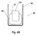
図4Bは、本発明の一実施形態に従ったワイパーの構造を概略的に示す。 FIG. 4B schematically shows the structure of a wiper according to an embodiment of the present invention.
ワイパー32’は、マーク消去装置30(図4A)などのマーク消去装置のワイピング(拭き取り)要素を表す。ワイパー32’の構造は平坦な面(例えば、直線状の摩擦動作の使用に好適なように)を有して示されているが、ワイパー32(図4A)などの円筒形または円形のワイパーの構造は、同心状に配置される同様のコンポーネントを含んでもよい。 The wiper 32 'represents the wiping element of a mark eraser, such as the mark eraser 30 (FIG. 4A). While the structure of the wiper 32 'is shown with a flat surface (eg, as suitable for use in linear frictional motion), a cylindrical or circular wiper such as the wiper 32 (FIG. 4A) is shown The structure may include similar components arranged concentrically.
ワイパー32’はコア35を含んでもよい。例えば、コア35は、金属または他の硬質材料を含んでもよい。コア35は弾性要素37により部分的にまたは完全に囲まれてもよい。例えば、弾性要素37はゴムまたは弾性高分子材料を含んでもよい。弾性要素37は、摩耗要素39により部分的または完全に囲まれてもよい。摩耗要素39は、粗い、エンボス加工されたまたは隆起した外面を示してもよい。例えば、摩耗要素39は、例えば、合成樹脂繊維の洗浄パッドに見られる材料と同様の粗いまたは繊維状の材料を含んでもよい。摩耗要素39は、ワイパーホイル34などの交換可能なワイパー材料により部分的または完全に囲まれてもよい。
The
図5は、本発明の一実施形態に係る印刷ヘッドノズル安定性評価方法のフローチャートである。 FIG. 5 is a flow chart of a print head nozzle stability evaluation method according to an embodiment of the present invention.
ノズル選択方法40は、基板の表面上に試験マークのセットを堆積させるかまたは印刷することを含む(工程42)。例えば、基板は再利用可能な基板であってもよいか、または単一の使用を意図されてもよい。
The
試験マークの印刷されたセットの画像が獲得されてもよい(工程44)。画像は獲得されると(または1つ以上の画像処理技術の適用後)、保存または記憶されてもよい。あるいは、画像は、パラメータまたはその画像において試験マークを特徴付ける特性値を抽出するために分析されてもよい。この場合、特性値は記憶されてもよい。 An image of the printed set of test marks may be obtained (step 44). The images may be saved or stored as they are acquired (or after application of one or more image processing techniques). Alternatively, the image may be analyzed to extract the parameters or characteristic values characterizing the test mark in the image. In this case, the characteristic values may be stored.
試験マークのセットの以前の画像が獲得されなかった場合(工程48)、または以前に画像化されたセットの数が分析に不十分である場合、試験マークのより多くのセットが印刷されてもよく、それらの画像が獲得されてもよい(工程42に戻る)。 If a previous image of the set of test marks has not been acquired (step 48), or if the number of previously imaged sets is insufficient for analysis, even if more sets of test marks are printed Well, those images may be acquired (return to step 42).
基板が再利用される場合、以前に印刷された試験マークは、より多くの試験マークを堆積させる前に基板から除去されてもよい(工程47)。そうでなければ、さらなる試験マークが、異なる基板上または同じ基板の別の部分上に印刷されてもよい(工程47は実施されない)。
If the substrate is to be reused, previously printed test marks may be removed from the substrate before depositing more test marks (step 47). Otherwise, additional test marks may be printed on a different substrate or on another part of the same substrate (
試験マークの十分な数のセットが以前に印刷され、画像化される(および分析される)場合、試験マークの画像(またはそれらの特性値)が比較されてもよい(工程48)。例えば、各マークを特徴付ける特性値が、セットの各々における対応する試験マークについての特性値の平均(または他の典型的な)値と比較されてもよい。あるいはまたはさらに、時間にわたって対応する試験マークの出現の変化の典型的な値(例えばセットの全てにおける試験マークの特性値の標準偏差または分散)が計算されてもよい。 If a sufficient number of sets of test marks have been previously printed and imaged (and analyzed), the images of the test marks (or their characteristic values) may be compared (step 48). For example, the characteristic values characterizing each mark may be compared to the average (or other typical) value of the characteristic values for the corresponding test mark in each of the sets. Alternatively or additionally, typical values of the change in appearance of the corresponding test mark over time (e.g. standard deviation or variance of test mark characteristic values in all of the sets) may be calculated.
試験マークの分析が、(例えば所定の基準に従って)1つ以上のマークについての(他の試験マークからまたは標準から)許容可能でない程度の偏差または変化を示す場合(工程50)、それらのマークを印刷したノズルは、選択されるノズルの群に含まれることから拒絶される(工程52)。例えば、ノズルは、変化により証明されると、安定性の欠如に起因して拒絶されてもよい。ノズルは、他の試験マークの分析から決定される標準から、または独立した標準もしくは条件から一貫して(または時折)逸れるノズルにより印刷された試験マークを拒絶されてもよい。例えば、試験マークは、所定の基準と一致しない位置または出現(中心ラインから極端に遠くに外れて印刷されたまたは基準ラインから離れすぎてもしくは近すぎて印刷された、非常に多くまたは非常に少なく印刷された)を有してもよい。 If the analysis of the test marks shows unacceptable deviations or changes (from the other test marks or from the standard) (for example according to a predetermined standard) (step 50), those marks The printed nozzles are rejected from being included in the group of selected nozzles (step 52). For example, the nozzle may be rejected due to the lack of stability as evidenced by the change. The nozzles may reject test marks printed by nozzles that deviate consistently (or occasionally) from a standard determined from analysis of other test marks, or from an independent standard or condition. For example, test marks may be printed at locations or occurrences that do not match a predetermined reference (printed extremely far from the center line or printed too far or too close to the reference line, too many or too few May be printed.
1つ以上のマークについての変化の計算された程度が許容可能である場合、対応するノズルは、選択されるノズルの群に含めるのに適し得る(工程54)。
If the calculated degree of change for one or more marks is acceptable, the corresponding nozzles may be suitable for inclusion in the group of selected nozzles (step 54).
Claims (20)
基板の表面上に試験マークを印刷するために前記複数のノズルの各々を反復して操作する工程であって、前記ノズルにより印刷される前記試験マークの各々は異なる時間に印刷される、工程と、
前記ノズルの各々を反復して操作する工程の間に少なくとも一度、前記試験マークの少なくとも一部を前記表面から消去する工程と、
前記ノズルの性能を示す特徴に関して、前記ノズルにより印刷された前記試験マークを検査する工程と、
を含む、方法。 A method of evaluating the performance of a plurality of nozzles of a print head, said method comprising
Repeatedly operating each of the plurality of nozzles to print test marks on the surface of the substrate, each of the test marks printed by the nozzles being printed at different times; ,
Erasing at least a portion of the test mark from the surface at least once during the step of repeatedly operating each of the nozzles;
Inspecting the test mark printed by the nozzle with respect to the characteristic indicating the performance of the nozzle;
Method, including.
試験マークを印刷するために前記複数のノズルの各々を反復して操作する工程であって、前記ノズルにより印刷される前記試験マークの各々は異なる時間に印刷される、工程と、
前記ノズルの安定性を決定するために前記ノズルにより印刷された前記試験マークを比較する工程と、
を含む、方法。 A method of evaluating the stability of a plurality of nozzles of a print head, said method comprising
Repeatedly operating each of the plurality of nozzles to print a test mark, each of the test marks printed by the nozzles being printed at different times;
Comparing the test marks printed by the nozzle to determine the stability of the nozzle;
Method, including.
前記複数のノズルのうちの1つのノズルにより印刷された前記試験マークの各々の画像を獲得する工程と、
前記ノズルの安定性の欠如を示す試験マーク間の相違を検出するために前記画像を比較する工程と、
を含む、請求項9に記載の方法。 The step of comparing the test marks is:
Acquiring an image of each of the test marks printed by one of the plurality of nozzles;
Comparing the images to detect differences between test marks indicating a lack of stability of the nozzle;
10. The method of claim 9, comprising:
複数のノズルの各々により基板表面上に印刷された試験マークの画像を獲得するための画像装置と、
獲得された前記画像の特徴を検出するように構成されるプロセッサであって、前記特徴は前記ノズルの性能を示す、プロセッサと、
前記基板表面から前記試験マークを消去するための消去装置と、
を含む、システム。 A system for evaluating the performance of multiple nozzles of a print head, said system comprising
An imaging device for acquiring an image of test marks printed on the substrate surface by each of the plurality of nozzles;
A processor configured to detect features of the acquired image, the features indicating the performance of the nozzle;
An erasing device for erasing the test marks from the substrate surface;
Including the system.
Applications Claiming Priority (3)
| Application Number | Priority Date | Filing Date | Title |
|---|---|---|---|
| US36673910P | 2010-07-22 | 2010-07-22 | |
| US61/366,739 | 2010-07-22 | ||
| PCT/IL2011/000577 WO2012011104A1 (en) | 2010-07-22 | 2011-07-19 | Printing head nozzle evaluation |
Publications (2)
| Publication Number | Publication Date |
|---|---|
| JP2013539405A true JP2013539405A (en) | 2013-10-24 |
| JP2013539405A5 JP2013539405A5 (en) | 2014-09-04 |
Family
ID=44545787
Family Applications (1)
| Application Number | Title | Priority Date | Filing Date |
|---|---|---|---|
| JP2013520285A Pending JP2013539405A (en) | 2010-07-22 | 2011-07-19 | Print head nozzle evaluation |
Country Status (6)
| Country | Link |
|---|---|
| US (2) | US10479122B2 (en) |
| EP (1) | EP2595814A1 (en) |
| JP (1) | JP2013539405A (en) |
| KR (1) | KR20140018172A (en) |
| CN (1) | CN103097141A (en) |
| WO (1) | WO2012011104A1 (en) |
Families Citing this family (14)
| Publication number | Priority date | Publication date | Assignee | Title |
|---|---|---|---|---|
| US20100066779A1 (en) | 2006-11-28 | 2010-03-18 | Hanan Gothait | Method and system for nozzle compensation in non-contact material deposition |
| KR101358340B1 (en) | 2008-11-30 | 2014-02-06 | 엑스제트 엘티디. | Method and system for applying materials on a substrate |
| EP2432640B1 (en) | 2009-05-18 | 2024-04-03 | Xjet Ltd. | Method and device for printing on heated substrates |
| CN102858547A (en) | 2010-05-02 | 2013-01-02 | Xjet有限公司 | Printing system with self-purge, sediment prevention and fumes removal arrangements |
| CN103097141A (en) * | 2010-07-22 | 2013-05-08 | 迅捷有限公司 | Printing head nozzle evaluation |
| JP5933883B2 (en) | 2010-10-18 | 2016-06-15 | エックスジェット エルティーディー. | Inkjet head storage and cleaning |
| CN104424167B (en) * | 2013-09-06 | 2017-11-10 | 北大方正集团有限公司 | The control method and system of mark in a kind of digital printing |
| CN105849208A (en) | 2013-10-17 | 2016-08-10 | Xjet有限公司 | Tungsten-carbide/cobalt ink composition for 3d inkjet printing |
| EP3442798B1 (en) * | 2016-04-11 | 2022-04-13 | Advanced Vision Technology (AVT) Ltd. | System and methods for detecting malfunctioning nozzles in a digital printing press |
| WO2019013760A1 (en) | 2017-07-11 | 2019-01-17 | Hewlett-Packard Development Company, L.P. | Fluidic die with primitive size greater than or equal to evaluator subset |
| WO2019013768A1 (en) | 2017-07-11 | 2019-01-17 | Hewlett-Packard Development Company, L.P. | Fluid actuator evaluation independent of actuation state |
| IL254078A0 (en) | 2017-08-21 | 2017-09-28 | Advanced Vision Tech A V T Ltd | System and method for generating images for inspection |
| CN110605924B (en) * | 2019-08-31 | 2021-03-30 | 森大(深圳)技术有限公司 | Printer stability continuous test method, storage medium, equipment and printer |
| US12090767B2 (en) | 2022-09-29 | 2024-09-17 | Ricoh Company, Ltd. | Defective nozzle locating mechanism |
Citations (1)
| Publication number | Priority date | Publication date | Assignee | Title |
|---|---|---|---|---|
| JPH0439041A (en) * | 1990-06-06 | 1992-02-10 | Canon Inc | Image forming device |
Family Cites Families (97)
| Publication number | Priority date | Publication date | Assignee | Title |
|---|---|---|---|---|
| US3451791A (en) | 1967-08-16 | 1969-06-24 | Du Pont | Cobalt-bonded tungsten carbide |
| US4847636A (en) | 1987-10-27 | 1989-07-11 | International Business Machines Corporation | Thermal drop-on-demand ink jet print head |
| US5136515A (en) | 1989-11-07 | 1992-08-04 | Richard Helinski | Method and means for constructing three-dimensional articles by particle deposition |
| JPH03184852A (en) | 1989-12-15 | 1991-08-12 | Canon Inc | Ink jet recording device |
| JPH04235054A (en) | 1991-01-09 | 1992-08-24 | Seiko Epson Corp | Ink jet recording apparatus |
| US5151377A (en) | 1991-03-07 | 1992-09-29 | Mobil Solar Energy Corporation | Method for forming contacts |
| JPH0690014A (en) | 1992-07-22 | 1994-03-29 | Mitsubishi Electric Corp | Thin solar cell and its production, etching method and automatic etching device, and production of semiconductor device |
| US5640183A (en) | 1994-07-20 | 1997-06-17 | Hewlett-Packard Company | Redundant nozzle dot matrix printheads and method of use |
| US6305769B1 (en) | 1995-09-27 | 2001-10-23 | 3D Systems, Inc. | Selective deposition modeling system and method |
| US5812158A (en) | 1996-01-18 | 1998-09-22 | Lexmark International, Inc. | Coated nozzle plate for ink jet printing |
| JPH11342598A (en) | 1998-03-31 | 1999-12-14 | Canon Inc | Recording device and recording head |
| JP2000310881A (en) | 1999-04-28 | 2000-11-07 | Minolta Co Ltd | Toner for toner jet |
| US6328418B1 (en) | 1999-08-11 | 2001-12-11 | Hitachi Koki Co., Ltd | Print head having array of printing elements for printer |
| US6514343B1 (en) | 1999-10-01 | 2003-02-04 | Tokyo Electron Limited | Coating apparatus |
| US20050104241A1 (en) | 2000-01-18 | 2005-05-19 | Objet Geometried Ltd. | Apparatus and method for three dimensional model printing |
| JP2001228320A (en) | 2000-02-21 | 2001-08-24 | Canon Inc | Method of manufacturing color filter and its manufacturing device |
| WO2002020864A2 (en) | 2000-06-16 | 2002-03-14 | Applied Materials, Inc. | System and method for depositing high dielectric constant materials and compatible conductive materials |
| US6595615B2 (en) * | 2001-01-02 | 2003-07-22 | 3M Innovative Properties Company | Method and apparatus for selection of inkjet printing parameters |
| AUPR399001A0 (en) | 2001-03-27 | 2001-04-26 | Silverbrook Research Pty. Ltd. | An apparatus and method(ART104) |
| US6536853B2 (en) | 2001-04-20 | 2003-03-25 | Caterpillar Inc | Arrangement for supporting a track chain of a track type work machine |
| US6454382B1 (en) * | 2001-05-11 | 2002-09-24 | Vladimir Galentovski | Malfunctioning nozzle detection apparatus |
| US6871307B2 (en) * | 2001-10-10 | 2005-03-22 | Tower Semiconductorltd. | Efficient test structure for non-volatile memory and other semiconductor integrated circuits |
| JP3948247B2 (en) | 2001-10-29 | 2007-07-25 | セイコーエプソン株式会社 | Method for forming a film pattern |
| US6736484B2 (en) | 2001-12-14 | 2004-05-18 | Seiko Epson Corporation | Liquid drop discharge method and discharge device; electro optical device, method of manufacture thereof, and device for manufacture thereof; color filter method of manufacture thereof, and device for manufacturing thereof; and device incorporating backing, method of manufacturing thereof, and device for manufacture thereof |
| US20040246294A1 (en) | 2002-04-22 | 2004-12-09 | Toyohiko Mitsuzawa | Method of cleaning print head |
| IL151354A (en) | 2002-08-20 | 2005-11-20 | Zach Moshe | Multi-printhead digital printer |
| US7131722B2 (en) | 2002-08-30 | 2006-11-07 | Konica Corporation | Ink jet printer and image recording method using a humidity detector to control the curing of an image |
| US6854828B2 (en) * | 2002-09-05 | 2005-02-15 | Hewlett-Packard Development Company, L.P. | Removal or mitigation of artifacts in composite-color incremental printing |
| JP4440523B2 (en) | 2002-09-19 | 2010-03-24 | 大日本印刷株式会社 | Organic EL display device by inkjet method, color filter manufacturing method, manufacturing device |
| JP2004139838A (en) | 2002-10-17 | 2004-05-13 | Noritake Co Ltd | Conductive paste and its use |
| JP3757963B2 (en) * | 2002-11-12 | 2006-03-22 | セイコーエプソン株式会社 | Functional droplet discharge head suction device, droplet discharge device, electro-optical device manufacturing method, electro-optical device, and electronic apparatus |
| US20040151978A1 (en) | 2003-01-30 | 2004-08-05 | Huang Wen C. | Method and apparatus for direct-write of functional materials with a controlled orientation |
| WO2004096556A2 (en) | 2003-04-28 | 2004-11-11 | Matsushita Electric Industrial Co. Ltd. | Nozzle head, line head using the same, and ink jet recording apparatus mounted with its line head |
| US7184069B2 (en) * | 2003-12-08 | 2007-02-27 | Kabushiki Kaisha Toshiba | Image-erasing apparatus and image-erasing method |
| JP4085429B2 (en) | 2004-05-14 | 2008-05-14 | 富士フイルム株式会社 | Image forming method and apparatus |
| JP4670274B2 (en) * | 2004-08-06 | 2011-04-13 | セイコーエプソン株式会社 | RECORDING MEDIUM CONVEYING BODY OF LIQUID EJECTING DEVICE, LIQUID EJECTING DEVICE |
| CN1733484A (en) * | 2004-08-12 | 2006-02-15 | 明基电通股份有限公司 | Method for detecting whether ink-jet head of printing machine meets the specification |
| JP4052295B2 (en) | 2004-08-25 | 2008-02-27 | セイコーエプソン株式会社 | MULTILAYER WIRING BOARD MANUFACTURING METHOD, ELECTRONIC DEVICE, AND ELECTRONIC DEVICE |
| JP4715209B2 (en) | 2004-09-01 | 2011-07-06 | コニカミノルタホールディングス株式会社 | Inkjet recording device |
| US7470016B2 (en) | 2004-12-03 | 2008-12-30 | Fujifilm Dimatix, Inc. | Introducing material into a printhead enclosure |
| US7236166B2 (en) | 2005-01-18 | 2007-06-26 | Stratasys, Inc. | High-resolution rapid manufacturing |
| US7344220B2 (en) | 2005-01-25 | 2008-03-18 | Fujifilm Dimatix, Inc. | Ink jet printing apparatus having non-contact print head maintenance station |
| US7274883B2 (en) * | 2005-03-22 | 2007-09-25 | Marvell International Technology Ltd. | Hybrid printer and related system and method |
| US7494607B2 (en) | 2005-04-14 | 2009-02-24 | E.I. Du Pont De Nemours And Company | Electroconductive thick film composition(s), electrode(s), and semiconductor device(s) formed therefrom |
| KR100636236B1 (en) * | 2005-05-24 | 2006-10-19 | 삼성전자주식회사 | Method and apparatus for detecting missing nozzle |
| JP2007061784A (en) | 2005-09-02 | 2007-03-15 | Seiko Epson Corp | Delivery apparatus for liquid-like substance, delivery method for liquid-like substance manufacturing apparatus for electro-optic apparatus and manufacturing method for electro-optic apparatus |
| US20070063366A1 (en) | 2005-09-19 | 2007-03-22 | 3D Systems, Inc. | Removal of fluid by-product from a solid deposition modeling process |
| KR100833232B1 (en) * | 2005-09-28 | 2008-05-28 | 삼성전자주식회사 | Ink jet image forming apparatus, and Method for compensating defective nozzle thereof |
| US7718092B2 (en) | 2005-10-11 | 2010-05-18 | E.I. Du Pont De Nemours And Company | Aluminum thick film composition(s), electrode(s), semiconductor device(s) and methods of making thereof |
| US20070107773A1 (en) | 2005-11-17 | 2007-05-17 | Palo Alto Research Center Incorporated | Bifacial cell with extruded gridline metallization |
| JP2007152161A (en) | 2005-11-30 | 2007-06-21 | Kubota Matsushitadenko Exterior Works Ltd | Coating device of construction plate |
| JP4735236B2 (en) * | 2005-12-20 | 2011-07-27 | 富士ゼロックス株式会社 | Nozzle check pattern and droplet discharge device |
| WO2007076424A1 (en) | 2005-12-27 | 2007-07-05 | Bp Corporation North America Inc. | Process for forming electrical contacts on a semiconductor wafer using a phase changing ink |
| KR100667850B1 (en) | 2006-01-03 | 2007-01-12 | 삼성전자주식회사 | Inkjet image forming apparatus and the control method of the same |
| US7857430B2 (en) | 2006-03-07 | 2010-12-28 | Fujifilm Corporation | Ink jet recording head and ink jet recording apparatus |
| DE102006015014B4 (en) | 2006-03-31 | 2008-07-24 | Uibel, Krishna, Dipl.-Ing. | Process for producing three-dimensional ceramic shaped bodies |
| DE502006007843D1 (en) * | 2006-07-06 | 2010-10-21 | Arvinmeritor Gmbh | A method of manufacturing a foamed vehicle part and a foamed vehicle part |
| US20080024557A1 (en) | 2006-07-26 | 2008-01-31 | Moynihan Edward R | Printing on a heated substrate |
| KR20090035019A (en) | 2006-08-03 | 2009-04-08 | 바스프 에스이 | Method for producing structured electrically-conductive surfaces |
| KR101320849B1 (en) * | 2006-08-14 | 2013-10-21 | 삼성전자주식회사 | Array type inkjet printer and method for determinating nozzle condition thereof |
| US7418216B2 (en) * | 2006-09-07 | 2008-08-26 | Xerox Corporation | System for predicting erasure of test patches in a printing apparatus |
| KR100726817B1 (en) | 2006-09-07 | 2007-06-11 | 한국생산기술연구원 | Manufacturing method for titanium hydride powders |
| JP2008073647A (en) | 2006-09-22 | 2008-04-03 | Fujifilm Corp | Liquid discharge apparatus and method of forming resist pattern |
| JP4869967B2 (en) | 2006-10-20 | 2012-02-08 | 三菱電機株式会社 | Method for roughening silicon substrate and method for producing photovoltaic device |
| US8322025B2 (en) | 2006-11-01 | 2012-12-04 | Solarworld Innovations Gmbh | Apparatus for forming a plurality of high-aspect ratio gridline structures |
| WO2008065657A2 (en) | 2006-11-28 | 2008-06-05 | Xjet Ltd. | Inkjet printing system with movable print heads and methods thereof |
| ES2388687T3 (en) | 2006-12-06 | 2012-10-17 | Dow Global Technologies Llc | Styrene and acrylonitrile copolymer foam with infrared attenuating agents |
| KR100931184B1 (en) | 2007-01-09 | 2009-12-10 | 주식회사 엘지화학 | Line pattern forming method using multiple nozzle head and display substrate manufactured by this method |
| JP5084333B2 (en) * | 2007-04-10 | 2012-11-28 | キヤノン株式会社 | Recording apparatus and conveyance error correction value acquisition method |
| WO2009017648A1 (en) | 2007-07-26 | 2009-02-05 | The Ex One Company, Llc | Nanoparticle suspensions for use in the three-dimensional printing process |
| TW200918325A (en) | 2007-08-31 | 2009-05-01 | Optomec Inc | AEROSOL JET® printing system for photovoltaic applications |
| JP4881271B2 (en) * | 2007-09-27 | 2012-02-22 | 富士フイルム株式会社 | Test chart, measuring method thereof, test chart measuring apparatus and program |
| CN101884113B (en) | 2007-12-11 | 2012-12-05 | 长青太阳能股份有限公司 | Photovoltaic panel and cell with fine fingers and method of manufacture of the same |
| JP5121437B2 (en) * | 2007-12-20 | 2013-01-16 | キヤノン株式会社 | Inkjet recording device |
| JP4992788B2 (en) * | 2008-03-27 | 2012-08-08 | セイコーエプソン株式会社 | Correction value calculation method and liquid ejection method |
| JP5236333B2 (en) * | 2008-03-31 | 2013-07-17 | セーレン株式会社 | Ink jet recording apparatus and discharge state inspection method thereof |
| ATE544601T1 (en) * | 2008-05-23 | 2012-02-15 | Oce Tech Bv | ADJUSTMENT OF A PRINTING ARRANGEMENT AND SUBSTRATE IN A PRINTING DEVICE |
| US8343869B2 (en) | 2008-06-24 | 2013-01-01 | Xjet Ltd. | Method for non-contact materials deposition |
| US8363261B1 (en) * | 2008-08-13 | 2013-01-29 | Marvell International Ltd. | Methods, software, circuits and apparatuses for detecting a malfunction in an imaging device |
| JP4995166B2 (en) | 2008-09-22 | 2012-08-08 | 東芝テック株式会社 | Liquid ejecting apparatus and control method thereof |
| KR101358340B1 (en) | 2008-11-30 | 2014-02-06 | 엑스제트 엘티디. | Method and system for applying materials on a substrate |
| EP2416356A1 (en) | 2009-03-30 | 2012-02-08 | Tokuyama Corporation | Process for producing metallized substrate and metallized substrate |
| EP2432640B1 (en) | 2009-05-18 | 2024-04-03 | Xjet Ltd. | Method and device for printing on heated substrates |
| EP2436519B1 (en) | 2009-05-29 | 2013-11-06 | Konica Minolta Holdings, Inc. | Inkjet recording device |
| JP5451221B2 (en) | 2009-07-09 | 2014-03-26 | キヤノン株式会社 | Inkjet recording apparatus and inkjet recording method |
| CN101670714A (en) * | 2009-09-18 | 2010-03-17 | 陈东 | Printer with specified print media and function of repeatedly using for multiple times |
| JP5725597B2 (en) * | 2010-03-19 | 2015-05-27 | 富士フイルム株式会社 | Fine pattern position detection method and apparatus, defective nozzle detection method and apparatus, and liquid ejection method and apparatus |
| CN102858547A (en) | 2010-05-02 | 2013-01-02 | Xjet有限公司 | Printing system with self-purge, sediment prevention and fumes removal arrangements |
| US8319808B2 (en) * | 2010-05-25 | 2012-11-27 | Kabushiki Kaisha Toshiba | Image forming apparatus |
| CN103097141A (en) | 2010-07-22 | 2013-05-08 | 迅捷有限公司 | Printing head nozzle evaluation |
| EP2597691B1 (en) * | 2010-07-23 | 2015-09-09 | Kyocera Corporation | Light irradiation device, light irradiation module, and printing device |
| JP5933883B2 (en) | 2010-10-18 | 2016-06-15 | エックスジェット エルティーディー. | Inkjet head storage and cleaning |
| EP2529694B1 (en) | 2011-05-31 | 2017-11-15 | Ivoclar Vivadent AG | Method for generative production of ceramic forms by means of 3D jet printing |
| WO2013179282A1 (en) | 2012-05-28 | 2013-12-05 | Xjet Ltd. | Solar cell electrically conductive structure and method |
| US20150298394A1 (en) | 2012-11-05 | 2015-10-22 | Yehoshua Sheinman | System and method for direct inkjet printing of 3d objects |
| US9234112B2 (en) | 2013-06-05 | 2016-01-12 | Korea Institute Of Machinery & Materials | Metal precursor powder, method of manufacturing conductive metal layer or pattern, and device including the same |
| CN105849208A (en) | 2013-10-17 | 2016-08-10 | Xjet有限公司 | Tungsten-carbide/cobalt ink composition for 3d inkjet printing |
-
2011
- 2011-07-19 CN CN2011800432796A patent/CN103097141A/en active Pending
- 2011-07-19 KR KR1020137004261A patent/KR20140018172A/en not_active Application Discontinuation
- 2011-07-19 JP JP2013520285A patent/JP2013539405A/en active Pending
- 2011-07-19 EP EP11746031.1A patent/EP2595814A1/en not_active Withdrawn
- 2011-07-19 US US13/811,296 patent/US10479122B2/en active Active
- 2011-07-19 WO PCT/IL2011/000577 patent/WO2012011104A1/en active Application Filing
-
2019
- 2019-10-15 US US16/653,224 patent/US20200039263A1/en not_active Abandoned
Patent Citations (1)
| Publication number | Priority date | Publication date | Assignee | Title |
|---|---|---|---|---|
| JPH0439041A (en) * | 1990-06-06 | 1992-02-10 | Canon Inc | Image forming device |
Also Published As
| Publication number | Publication date |
|---|---|
| WO2012011104A1 (en) | 2012-01-26 |
| KR20140018172A (en) | 2014-02-12 |
| US10479122B2 (en) | 2019-11-19 |
| EP2595814A1 (en) | 2013-05-29 |
| US20130176355A1 (en) | 2013-07-11 |
| CN103097141A (en) | 2013-05-08 |
| US20200039263A1 (en) | 2020-02-06 |
Similar Documents
| Publication | Publication Date | Title |
|---|---|---|
| JP2013539405A (en) | Print head nozzle evaluation | |
| KR20070085273A (en) | Apparatus and methods for servicing 3d printers | |
| KR20180031007A (en) | Operation of printing nozzles in stacking and apparatus for cleaning printing nozzles | |
| US9519447B2 (en) | Apparatus and method for determining suitable printing conditions for printing sheets in a printing system | |
| US8901012B2 (en) | Semiconductor manufacturing apparatus and method for manufacturing semiconductor device | |
| JP2013539405A5 (en) | ||
| JP4931703B2 (en) | Inspection method for liquid ejection device and cleaning device therefor | |
| JP5613082B2 (en) | Wiping unit, maintenance device, liquid ejection device, and wiping method | |
| JP2012166159A (en) | Ejection device, and ejection method | |
| KR101053144B1 (en) | Apparatus and method of coating treatment solution | |
| JP6853865B2 (en) | Systems and methods for assessing surface quality by optically analyzing ejected droplets | |
| JP2011178068A (en) | Device and method for cleaning head, and image recording apparatus | |
| TWI404571B (en) | Maintenance apparatus and discharge apparatus | |
| JP6111425B2 (en) | Board inspection method | |
| JP7005850B2 (en) | Methods and Devices for Creating Printed Microarrays | |
| JP5078603B2 (en) | Processing method of plate | |
| JP6299910B2 (en) | Foreign matter inspection method, imprint method, and foreign matter inspection device | |
| US20240208228A1 (en) | Print apparatus maintenance | |
| US10576754B2 (en) | System and method for verifying the cure of ultraviolet curable materials in a three-dimensional 3D object printer | |
| US20230101546A1 (en) | Control unit and substrate treating apparatus including the same | |
| US20240034055A1 (en) | Droplet analysis unit and substrate treatment apparatus including the same | |
| CN117984661A (en) | Substrate processing apparatus and method | |
| JP2018039117A (en) | Printing plate state control device for gravure plate | |
| JP5426737B2 (en) | Processing method of plate | |
| CN115780171A (en) | Coating device and droplet discharge inspection method |
Legal Events
| Date | Code | Title | Description |
|---|---|---|---|
| A521 | Written amendment |
Free format text: JAPANESE INTERMEDIATE CODE: A523 Effective date: 20140716 |
|
| A621 | Written request for application examination |
Free format text: JAPANESE INTERMEDIATE CODE: A621 Effective date: 20140716 |
|
| A977 | Report on retrieval |
Free format text: JAPANESE INTERMEDIATE CODE: A971007 Effective date: 20150529 |
|
| A131 | Notification of reasons for refusal |
Free format text: JAPANESE INTERMEDIATE CODE: A131 Effective date: 20150609 |
|
| A02 | Decision of refusal |
Free format text: JAPANESE INTERMEDIATE CODE: A02 Effective date: 20151110 |