JP2013533809A - Method for performing periodic tooth surface correction, machine tool, and computer-readable medium - Google Patents
Method for performing periodic tooth surface correction, machine tool, and computer-readable medium Download PDFInfo
- Publication number
- JP2013533809A JP2013533809A JP2013517103A JP2013517103A JP2013533809A JP 2013533809 A JP2013533809 A JP 2013533809A JP 2013517103 A JP2013517103 A JP 2013517103A JP 2013517103 A JP2013517103 A JP 2013517103A JP 2013533809 A JP2013533809 A JP 2013533809A
- Authority
- JP
- Japan
- Prior art keywords
- workpiece
- tool
- contact line
- tooth
- tooth surface
- Prior art date
- Legal status (The legal status is an assumption and is not a legal conclusion. Google has not performed a legal analysis and makes no representation as to the accuracy of the status listed.)
- Pending
Links
Images
Classifications
-
- B—PERFORMING OPERATIONS; TRANSPORTING
- B23—MACHINE TOOLS; METAL-WORKING NOT OTHERWISE PROVIDED FOR
- B23F—MAKING GEARS OR TOOTHED RACKS
- B23F21/00—Tools specially adapted for use in machines for manufacturing gear teeth
-
- B—PERFORMING OPERATIONS; TRANSPORTING
- B23—MACHINE TOOLS; METAL-WORKING NOT OTHERWISE PROVIDED FOR
- B23F—MAKING GEARS OR TOOTHED RACKS
- B23F19/00—Finishing gear teeth by other tools than those used for manufacturing gear teeth
-
- B—PERFORMING OPERATIONS; TRANSPORTING
- B23—MACHINE TOOLS; METAL-WORKING NOT OTHERWISE PROVIDED FOR
- B23F—MAKING GEARS OR TOOTHED RACKS
- B23F19/00—Finishing gear teeth by other tools than those used for manufacturing gear teeth
- B23F19/002—Modifying the theoretical tooth flank form, e.g. crowning
-
- B—PERFORMING OPERATIONS; TRANSPORTING
- B24—GRINDING; POLISHING
- B24B—MACHINES, DEVICES, OR PROCESSES FOR GRINDING OR POLISHING; DRESSING OR CONDITIONING OF ABRADING SURFACES; FEEDING OF GRINDING, POLISHING, OR LAPPING AGENTS
- B24B19/00—Single-purpose machines or devices for particular grinding operations not covered by any other main group
-
- G—PHYSICS
- G05—CONTROLLING; REGULATING
- G05B—CONTROL OR REGULATING SYSTEMS IN GENERAL; FUNCTIONAL ELEMENTS OF SUCH SYSTEMS; MONITORING OR TESTING ARRANGEMENTS FOR SUCH SYSTEMS OR ELEMENTS
- G05B19/00—Programme-control systems
- G05B19/02—Programme-control systems electric
- G05B19/18—Numerical control [NC], i.e. automatically operating machines, in particular machine tools, e.g. in a manufacturing environment, so as to execute positioning, movement or co-ordinated operations by means of programme data in numerical form
- G05B19/182—Numerical control [NC], i.e. automatically operating machines, in particular machine tools, e.g. in a manufacturing environment, so as to execute positioning, movement or co-ordinated operations by means of programme data in numerical form characterised by the machine tool function, e.g. thread cutting, cam making, tool direction control
- G05B19/186—Generation of screw- or gearlike surfaces
-
- Y—GENERAL TAGGING OF NEW TECHNOLOGICAL DEVELOPMENTS; GENERAL TAGGING OF CROSS-SECTIONAL TECHNOLOGIES SPANNING OVER SEVERAL SECTIONS OF THE IPC; TECHNICAL SUBJECTS COVERED BY FORMER USPC CROSS-REFERENCE ART COLLECTIONS [XRACs] AND DIGESTS
- Y02—TECHNOLOGIES OR APPLICATIONS FOR MITIGATION OR ADAPTATION AGAINST CLIMATE CHANGE
- Y02P—CLIMATE CHANGE MITIGATION TECHNOLOGIES IN THE PRODUCTION OR PROCESSING OF GOODS
- Y02P90/00—Enabling technologies with a potential contribution to greenhouse gas [GHG] emissions mitigation
- Y02P90/02—Total factory control, e.g. smart factories, flexible manufacturing systems [FMS] or integrated manufacturing systems [IMS]
Abstract
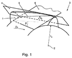
本発明は周期的歯面修正を行う方法に関する。本方法では、工具が、軸線に沿うワーク3の歯1の歯面に対して行われる第1の行程の間に、この工具は、ワークの中心軸線2に対して傾斜角βだけ回転させられるとともにワークの被切削端面に直交している平面において被せ面4を作成し、被せ面4が、噛合平面6に対して直交するように方向付けられ、したがって、第1の行程の間、加工軌跡が、ワークに及ぼす工具の加工効果により第1の対応する転動位置の第1の接線5に沿って生成される。第1の接触線5は、ワークと同じ傾斜角βの任意の転動相手との間の第1の接触線5に対応する第2の接触線を同時に形成し、更に、歯面修正は、第1の接触線5に沿った工具および/またはワークの法線方向への工具の値Zu分の前進により行われるとともに、個々の行程の間、ワークは転動動作を行わない。
【選択図】 図1The present invention relates to a method for performing periodic tooth surface correction. In this method, the tool is rotated by an inclination angle β with respect to the central axis 2 of the workpiece during a first stroke performed on the tooth surface of the tooth 1 of the workpiece 3 along the axis. And the covering surface 4 is created in a plane orthogonal to the workpiece end face, and the covering surface 4 is oriented so as to be orthogonal to the meshing plane 6, and therefore the machining trajectory during the first stroke. Is generated along the first tangent 5 of the first corresponding rolling position due to the machining effect of the tool on the workpiece. The first contact line 5 simultaneously forms a second contact line corresponding to the first contact line 5 between an arbitrary rolling partner having the same inclination angle β as the workpiece, and the tooth surface correction is This is done by advancing the tool value Z u along the first contact line 5 in the tool and / or workpiece normal direction and the workpiece does not roll during the individual strokes.
[Selection] Figure 1
Description
本発明は、周期的歯面修正を行う方法であって、工具が、軸線に沿うワークの歯の歯面に対して行われる第1の行程の間に用いられ、この工具は、ワークの中心軸線に対してねじれ角βだけ回転させられるとともに被せ面(enshrouding plane)を作成する方法に関する。 The present invention is a method for performing periodic tooth flank correction, wherein a tool is used during a first stroke performed on the tooth flank of a workpiece along an axis, the tool being centered on the workpiece. The present invention relates to a method for creating an covering plane that is rotated by a twist angle β with respect to an axis.
今日では、歯車機構の騒音特性が、環境への意識の高まりの一環として増々重要になっている。許容される騒音放出の上限値は、一方では顧客の要求、他方では法規定によって決まる。これは、産業上の利用分野にだけでなく民間利用にも当てはまる。歯車対および/または歯の噛み合いが歯車機構における最も重要な騒音源の1つであるため、この点では、構造上の改善のみならず製造技術の分野での改善を実現するための努力は当然のことである。振動の励振と歯車対の騒音、ひいては歯車機構からの騒音放出を効果的に低減する1つの可能性は、歯面修正を使用することにある。かかる歯面修正は、フランク修整とも呼ばれる。 Today, the noise characteristics of gear mechanisms are becoming increasingly important as part of increasing environmental awareness. The upper limit of allowable noise emission is determined on the one hand by customer requirements and on the other hand by legal regulations. This applies not only to industrial applications but also to private use. Since gear pairs and / or tooth meshing is one of the most important noise sources in gear mechanisms, in this respect, efforts to realize not only structural improvements but also improvements in the field of manufacturing technology are natural. That is. One possibility to effectively reduce vibration excitation and gear pair noise, and thus noise emissions from the gear mechanism, is to use tooth surface modification. Such tooth surface correction is also called flank modification.
周期的歯面修正および/または周期的励振修整は、所与の設計負荷の下で平歯車対の歯車の励振を完全に除去できる特別な解決策であり、加えて、設計負荷前後の広い負荷範囲も十分に改善される。 Periodic tooth surface modification and / or periodic excitation modification is a special solution that can completely eliminate the excitation of spur gear pairs under a given design load, plus a wide load before and after the design load. The range is also improved sufficiently.
加えて、この種の歯面修正は、所与の平歯車対の耐荷力の個々の最適化だけでなく、歯が正弦波形状を有する場合には、歯の噛み合わせの励振機能の個々の高調波成分の処理を可能にする。 In addition, this kind of tooth surface modification is not only the individual optimization of the load bearing capacity of a given spur gear pair, but also the individual meshing excitation function if the tooth has a sinusoidal shape. Allows processing of harmonic components.
関連する従来技術は、論文「Einfluss von Flankenkorrekturen auf das Anregungsverhalten gerad−und schragverzahnter Stirnradpaarungen」(「直歯と斜歯を有する平歯車対の励振特性に及ぼすフランク修整の影響」)で知られている。この論文は、2006年12月6日にミュンヘン工科大学に提出され、2007年6月20日にその機械工学部に受け入れられた。この論文は、http://deposit.ddb.de/のドイツ国立図書館のサーバー上でURN番号「um:nbn:de:bvb:91−diss−20080122−645505−1−7」により取得することができる。作用領域に関して、周期的歯面修正(上で既に述べた通り、周期的励振修整とも呼ばれる)は、正弦波形状および所与の設計負荷の場合、振幅値、周期、位相長さおよび向きにより明確に表される。振幅は、歯状部の所与のマクロ形状およびミクロ形状、ならびに処理すべき歯の噛み合せの励振機能の高調波成分によって決まる。周期は、処理すべき歯の噛み合せの高調波成分によってのみ決まり、かつ基本高調波の基本ピッチの長さに等しい長さ、ならびに相対的により高い高調波成分に対する基本ピッチの全約数(whole divisor)の長さに等しい長さを有する。歯の噛み合せの励振機能の各高調波成分はそれ自体フェージングを有し、加えて、それは歯状部のマクロ形状およびマクロ形状によって決まる。周期的歯面修正の向きは、いわゆる基礎円のいわゆるねじれ角と一致する。 The related prior art is the article “Einflus von Frankenkorrekturen auf das Anregungsverhalten gerad-und schragverzahnter Stirradpaarungen with the effect of straight gears with straight teeth and inclined teeth. This paper was submitted to the Technical University of Munich on 6 December 2006 and accepted by the School of Mechanical Engineering on 20 June 2007. This article is available at http: // deposit. ddb. The URN number “um: nbn: de: bvb: 91-diss-20080122-6455505-1-7” can be obtained on the server of the German National Library in de /. With respect to the working area, periodic tooth surface modification (also referred to as periodic excitation modification, as already mentioned above) is more apparent by amplitude value, period, phase length and orientation for a sinusoidal shape and a given design load. It is expressed in The amplitude depends on the given macro and micro shape of the tooth and the harmonic components of the excitation function of the tooth mesh to be treated. The period is determined only by the harmonic content of the tooth mesh to be treated and is equal to the length of the fundamental pitch of the fundamental harmonic, as well as the total divisor of the fundamental pitch for the relatively higher harmonic components. ). Each harmonic component of the tooth meshing excitation function has its own fading, in addition, it depends on the macro shape and macro shape of the tooth. The direction of the periodic tooth surface correction coincides with the so-called twist angle of the so-called basic circle.
周期的歯面修正の1つの特徴は、各個々の接触線が特定の修整量を含む、つまり、所与の接触線のすべての点が、作用面に対して法線方向に同じ量(ゼロであってもよい)だけ変位するということである。 One feature of periodic tooth surface modification is that each individual contact line contains a certain amount of modification, i.e., all points of a given contact line have the same amount normal to the working surface (zero). It may be displaced).
現在、周期的歯面修正は、個々の生産準備および研究プロジェクトにおいて位相的処理を活用して作成される。この点では、例として独国特許第2307493号明細書が参照される。 Currently, periodic tooth surface modifications are created utilizing topological processing in individual production preparation and research projects. In this respect, reference is made, for example, to DE 2307493.
しかしながら、そのような位相的処理は、経済的ではなく、再現することが難しいと判明している。それゆえに、経済的であり、大規模で再現可能な方式で用いられるのに適合した方法が必要である。 However, such topological processing is not economical and has proven difficult to reproduce. Therefore, there is a need for a method that is economical and adapted to be used in a large and reproducible manner.
更に、位相的処理を可能にする適切なプログラムを作成することは非常に複雑である。また、独国特許第3734828号明細書、独国特許第10208531号明細書および独国特許第4112122号明細書に記載の従来技術で知られる方法にも、これらの2つの欠点がある。欧州特許出願公開第0074930号明細書、欧州特許出願公開第0180747号明細書および欧州特許出願公開第0132582号明細書で知られる代替的な方法では、既に一定の改善を示しているが、未だ望ましい成果が得られていない。 Furthermore, creating an appropriate program that allows topological processing is very complex. The methods known in the prior art described in German Patent No. 3733428, German Patent No. 10208531 and German Patent No. 4112122 also have these two drawbacks. The alternative methods known from EP-A-0074930, EP-A-0180747 and EP-A-0132582 already show some improvement but are still desirable. No results have been obtained.
円筒歯車の歯切り加工、例えば、成形加工および転動(ローリング)型加工が十分に知られている。すべての転動型加工において、ワークおよび工具は転動運動を行う。ワークおよび工具は、2つの歯車装置要素のように互いに転動する。この転動接触の間、インボリュートは、ワークの同時運動に伴い、直線状の基準プロファイルを有する工具により覆われる。切削刃の先端は、歯面が一連のプロファイル切削で生成されるように、どの位置でもインボリュートプロファイルに接している。ホブ切りとして知られる連続法は、幅の広い歯車の場合、高い切削速度が達成されるという利点を有する。ホブの包囲体(envepoing body)は、円筒形のインボリュートウォームである。転動運動の間、工具およびワークは回転する。切削運動は、回転する切削刃により行われる。平歯車を製作するために、切削刃およびワークは、ワーク軸線方向(すなわち、ここでは中心軸線の方向)に互いに対して変位し、転動運動が同時に行われる。ホブ切りは、一連の製作での歯車の予備歯切りに頻繁に用いられる。加えて、この方法は、軟質の、焼戻し、かつ硬化させた大きな歯形、特別な歯形およびスプラインプロファイルを有するワークの予備歯切りおよび仕上げ歯切りに用いられる。しかしながら、この方法は、長い誘導斜面および振れだけでなく、内歯製作の不可能性を伴う限りにおいて、不利であることが判明した。 Gear cutting of cylindrical gears, for example, forming and rolling (rolling) mold processing are well known. In all rolling processes, the workpiece and tool perform a rolling motion. The workpiece and tool roll on each other like two gearing elements. During this rolling contact, the involute is covered with a tool having a linear reference profile with the simultaneous movement of the workpiece. The tip of the cutting blade is in contact with the involute profile at any position so that the tooth surface is generated by a series of profile cuts. A continuous process known as hobbing has the advantage that a high cutting speed is achieved for wide gears. The hob's enveloping body is a cylindrical involute worm. During the rolling motion, the tool and workpiece rotate. The cutting motion is performed by a rotating cutting blade. In order to produce a spur gear, the cutting blade and the workpiece are displaced relative to each other in the workpiece axial direction (that is, here in the direction of the central axis), and rolling motions are performed simultaneously. Hobbing is frequently used for gear pre-cutting in a series of productions. In addition, this method is used for pre- and finish gear cutting of soft, tempered and hardened large tooth profiles, special tooth profiles and spline profiles. However, this method has proved disadvantageous as long as it involves not only long guiding slopes and deflections but also the inability to produce internal teeth.
別の既知の方法は、連続的転動型の加工としても分類される歯車形削りである。歯切りの間、切削ホイールとワークは、平歯車装置の歯車と相手歯車のように互いに転動する。同時に、切削ホイールは、その往復運動を通じて切削運動を行う。直歯の場合、往復運動はワークの軸線方向で生じる。斜歯歯車機構の場合、斜歯を有する切削ホイールは、作成されるねじれ角βに対応する斜歯切削運動を行う。結果として、直歯付き平歯車、またはフランクが後部に徐々に細くなる斜歯付き平歯車が得られる。これにより、切削作業に必要な逃げ角が形成される。このような歯車形削りは、直歯および斜歯を有する内歯および外歯をワーク上に形成するために用いられる。また、利点として非常に小さな振れが達成されるが、空行程が行われる。右と左の歯斜面については、異なる工具案内路および工具を使用しなければならない。これは特に不利である。その上、割出創成法である代替的な創成平削りが用いられるとき、内歯を製作することが不可能であり、空行程の欠点を受け入れる必要がある。簡単で安価な工具、小さな誘導斜面および精密なフランク形状が実現可能であるが、これらの利点では、不利点を十分に補うことはできない。歯が形成されるワークは、この方法の場合、ラックカッター(すなわち、平削り工具)に対して転動する。工具により切削運動(すなわち、上下運動)が行われる。戻り行程の間、ラックカッターを上昇させる。歯の切削を1つ仕上げたときに、ワークを1歯ピッチだけ回転させる。ここでは、工具は、そのフランクが後部に切り離される(cut free)ラックである。後者はラックカッターと呼ばれる。 Another known method is gear shaping, which is also classified as a continuous rolling type machining. During gear cutting, the cutting wheel and the work roll together like a spur gear and a counter gear. At the same time, the cutting wheel performs a cutting motion through its reciprocating motion. In the case of straight teeth, the reciprocating motion occurs in the axial direction of the workpiece. In the case of an inclined gear mechanism, a cutting wheel having inclined teeth performs an inclined tooth cutting motion corresponding to the created twist angle β. As a result, a straight toothed spur gear or a beveled spur gear whose flank gradually narrows toward the rear is obtained. Thereby, the clearance angle required for the cutting operation is formed. Such gear shaping is used to form internal teeth and external teeth having straight teeth and oblique teeth on the workpiece. Also, as an advantage, a very small runout is achieved, but an empty stroke is performed. Different tool guides and tools must be used for the right and left tooth slopes. This is particularly disadvantageous. Moreover, when an alternative generation planing, which is an index generation method, is used, it is impossible to produce internal teeth and it is necessary to accept the disadvantages of the idle stroke. Simple and inexpensive tools, small guiding bevels and precise flank shapes are feasible, but these advantages cannot fully compensate for the disadvantages. In this method, the workpiece on which teeth are formed rolls against a rack cutter (ie, a planing tool). Cutting motion (ie, vertical motion) is performed by the tool. Raise the rack cutter during the return stroke. When one tooth has been cut, the workpiece is rotated by one tooth pitch. Here, the tool is a rack whose flank is cut free. The latter is called a rack cutter.
代替案として総形フライス削りが用いられるとき、切削刃は、切削される歯溝のプロファイルを有する。回転する切削刃およびワークは、ワーク軸線方向に互いに対して変位する。直歯が形成されるとき、ワークは回転しない。歯溝を1つ仕上げたときに初めて、製作中の歯車を1ピッチだけ前進させる。斜歯の場合、ワークが連続回転を行い、その回転はねじれ角βに対応する。更にこの場合、単一の分割法(single partitioning method)で、分割が行われる。総形フライス削りは、エンドミルまたは側フライスカッターを用いて実行することができる。この方法により、ドレスし易い安価な工具の有効活用が可能になることは事実であるが、異なるインボリュート曲率に対しては異なる転動曲線が必要となる。 As an alternative, when full milling is used, the cutting blade has a profile of the tooth space to be cut. The rotating cutting blade and the workpiece are displaced relative to each other in the workpiece axial direction. When straight teeth are formed, the workpiece does not rotate. Only when one tooth gap is finished, the gear being manufactured is advanced by one pitch. In the case of inclined teeth, the workpiece rotates continuously, and the rotation corresponds to the twist angle β. Further, in this case, the division is performed by a single partitioning method. Full milling can be performed using an end mill or a side milling cutter. Although it is true that an inexpensive tool that is easy to dress can be used effectively by this method, different rolling curves are required for different involute curvatures.
歯面修正を達成するためには、いわゆる創成研削が使用するべき明白な方法である。この方法が用いられるとき、インボリュートプロファイルは、2つの円盤形砥石車間の歯車を砥石車と転動接触させて移動させることにより生成される。この方法は、テンプレートの使用、または適切な制御の使用を含む。位相的研削は、最終的な解析では、いわゆる0°法またはナイルス法を用いて行われる。 To achieve tooth correction, so-called generating grinding is an obvious method to use. When this method is used, the involute profile is generated by moving the gear between the two disc-shaped grinding wheels in rolling contact with the grinding wheel. This method involves the use of templates or the use of appropriate controls. Topological grinding is performed using a so-called 0 ° method or Niles method in the final analysis.
砥石車は、(例えば、いわゆる0°法の場合には)平行に配設される。軸線方向への研削送りをワークにより行い、ワークを軸線方向に往復運動させる。送り経路の終端で分割がなされる。各作業サイクルにおいて、2つの歯面が同時に案内される。送りは、砥石車を互いに向けて移動させることにより行われる。この方法もまた、工具の異なる転動曲線を有効に保持しなければならないという欠点を伴う。 The grinding wheels are arranged in parallel (for example in the case of the so-called 0 ° method). Grinding feed in the axial direction is performed by the workpiece, and the workpiece is reciprocated in the axial direction. Splitting is done at the end of the feed path. In each work cycle, two tooth surfaces are guided simultaneously. The feeding is performed by moving the grinding wheels toward each other. This method also has the disadvantage that the different rolling curves of the tool must be maintained effectively.
今日の視点からすると、プロファイル研削法を用いて位相的研削を行うことはできない。しかしながら、ワークと工具との間に点接触または略点接触を確立できるという前提で、創成研削法を活用すれば、位相的研削が可能である。 From today's point of view, phase grinding cannot be performed using the profile grinding method. However, it is possible to perform topological grinding by using the creation grinding method on the premise that point contact or substantially point contact can be established between the workpiece and the tool.
しかしながら、連続創成研削法が用いられるとき、ウォーム形砥石車の複数の歯がワークの複数の歯と噛み合うので、位相的研削を達成することは困難である。α°法を活用する場合、点接触が存在しないので、位相的研削は理論上不可能である。0°法および/またはナイルス法(円錐形砥石車での割出創成研削)の場合、(略)点接触ひいては位相的研削処理を実現することができる。 However, when the continuous generating grinding method is used, it is difficult to achieve topological grinding because the teeth of the worm-type grinding wheel mesh with the teeth of the workpiece. When utilizing the α ° method, there is no point contact, so topological grinding is theoretically impossible. In the case of the 0 ° method and / or the Niles method (index generation grinding with a conical grinding wheel), (substantially) point contact and thus phase grinding can be realized.
これまでは、位相的研削を実現する場合は必ず、複雑な制御を行う必要があった。加えて、ワークが加工されている間、複数の可動軸が存在する。しかし、移動する軸の数が多いほど、誤差率が高くなる。 Up to now, complex control has always been necessary to achieve topological grinding. In addition, there are a plurality of movable axes while the workpiece is being machined. However, the error rate increases as the number of moving axes increases.
それゆえ、簡単な手段を活用してより良好な歯面修正を達成することが本発明の目的である。 Therefore, it is an object of the present invention to achieve better tooth surface correction utilizing simple means.
本発明によれば、請求項1に記載の方法、請求項8に記載の工作機械、および請求項9に記載のコンピュータ可読媒体によりこの目的が達成される。 According to the invention, this object is achieved by a method according to claim 1, a machine tool according to claim 8 and a computer readable medium according to claim 9.
被せ面が作用面に対して直交するように方向付けられ、したがって、第1の行程の間、加工軌跡が、ワークに及ぼす工具の加工効果により第1の対応する転動位置の第1の接線に正確に沿って生成されることで目的が達成されるが、第1の接触線は、好ましくは、ワークと同じねじれ角βの任意の転動相手との間の第1の接触線に対応する第2の接触線を同時に形成し、更に、歯面修正は、第1の接触線に沿った工具および/またはワークの法線方向への工具の値zu分の前進により行われるとともに、個々の行程の間、ワークは転動動作を行わない。 The covering surface is oriented so that it is perpendicular to the working surface, so that during the first stroke, the machining trajectory is a first tangent of the first corresponding rolling position due to the machining effect of the tool on the workpiece. The first contact line preferably corresponds to the first contact line between the workpiece and any rolling partner with the same helix angle β. A second contact line is formed at the same time, and the tooth surface correction is performed by advancing the tool value z u along the first contact line in the direction of the normal of the tool and / or workpiece, During each stroke, the workpiece does not roll.
このように、第1の接触線に沿ってワークからより多くまたは少なく素材が削られ、歯面修正が、ワークと同じねじれ角の任意の転動相手との間の第1の位置に対して達成される。この実現は、極めて簡単であり、高精度値を可能にする。それゆえ、意外にも、驚くほど簡単な解決策で課題が解決された。 In this way, more or less material is scraped from the workpiece along the first contact line, and the tooth surface correction is relative to the first position between any workpiece with the same helix angle as the workpiece. Achieved. This realization is very simple and allows high precision values. Surprisingly, the problem was solved with a surprisingly simple solution.
その課題はまた、その方法を行うように構成された工作機械により解決される。また、処理装置により実行されたとき、この方法による工作機械の開ループ制御または閉ループ制御を生じさせる命令を有するコンピュータ可読媒体もこの課題を解決する。 The problem is also solved by a machine tool configured to perform the method. A computer readable medium having instructions that, when executed by a processing device, cause open or closed loop control of a machine tool according to this method also solves this problem.
妥当な費用および簡単な運動学により、平歯車対に起因する騒音を最小限に抑えるために周期的歯面修正が達成される。振幅がごく僅かであれば、この方法は、使用する工作機械の精密さによってのみ制限される。 With reasonable cost and simple kinematics, periodic tooth flank correction is achieved to minimize noise due to spur gear pairs. If the amplitude is negligible, this method is limited only by the precision of the machine tool used.
このような方法では、既存の方法よりも更に高い正確さかつ高い再現性で、より迅速に周期的歯面修正が作成される。この方法はまた、点接触ではなく、被せ面に基づいているので、位相的研削と比較して、プログラミングおよび制御技術へのより少ない投資で実現可能である。位相的研削の場合を除き、この方法は、連続創成研削法およびα°法に基づき実現可能である。 In such a method, periodic tooth surface correction is created more quickly with higher accuracy and higher reproducibility than existing methods. This method is also possible with less investment in programming and control technology compared to topological grinding because it is based on a covered surface rather than a point contact. Except in the case of topological grinding, this method can be realized based on the continuous generation grinding method and the α ° method.
有利な実施形態を従属クレームに記載し、以下により詳細に説明する。 Advantageous embodiments are set forth in the dependent claims and are described in more detail below.
例えば、個々の行程の間、値zuが不変のままである場合、有利である。したがって、同じ修正値を、接触線全体にわたって達成することができ、これにより、第1の接触線の傍に延在する第2の接触線と比較して、僅かに高いまたは僅かに低い第1の接触線が生じる。当然ながら、値zuは第1の接触線またはその後の接触線に沿って変化してもよい。 For example, it is advantageous if the value z u remains unchanged during the individual strokes. Thus, the same correction value can be achieved over the entire contact line, whereby the first is slightly higher or slightly lower compared to the second contact line extending beside the first contact line. The contact line is generated. Of course, the value z u may vary along the first contact line or a subsequent contact line.
第1の行程により丁度第1の接触線上で第1の歯面修正を終えた後、第2の歯面修正を行うために、第2の行程が丁度第3の接触線上で行われるとき、前記第3の接触線は、第2の個別の転動位置でのワークと同じねじれ角βの任意の転動相手との間の第4の接触線に対応するが、そのようにして、最終的に歯面幅全体を処理することができる。 After finishing the first tooth surface correction just on the first contact line by the first stroke, the second stroke is performed just on the third contact line to perform the second tooth surface correction, Said third contact line corresponds to the fourth contact line between any rolling counterparts with the same helix angle β as the workpiece at the second individual rolling position, but as such, the final Thus, the entire tooth surface width can be processed.
ワークが直歯または斜歯付き部品として形成される場合、有利である。その点では、特に良好な効率を得ることができる。 It is advantageous if the workpiece is formed as a straight or inclined part. In that respect, particularly good efficiency can be obtained.
使用方法が加工処理であるとき、従来の低コストの工作機械を使用することができる。 When the method of use is machining, a conventional low-cost machine tool can be used.
特に精密な方法では、かかる方法を使用するときに有利である幾何学形状に構成されたまたは構成されていない工具が活用される。 Particularly precise methods take advantage of tools configured or not configured in a geometry that is advantageous when using such methods.
特に良好な品質を達成するために、1つまたは複数の円錐形砥石車および/または1つまたは複数のウォーム形砥石車および/または1つまたは複数の円盤形砥石車が用いられる場合、有利である。 In order to achieve particularly good quality, it is advantageous if one or more conical grinding wheels and / or one or more worm-shaped grinding wheels and / or one or more disc-shaped grinding wheels are used. is there.
更に、ワークが内歯部品または外歯部品として形成される場合、有利である。 Furthermore, it is advantageous if the workpiece is formed as an internal tooth part or an external tooth part.
以下では、本発明を、図面の助けを借りて更に詳細に説明するが、唯一の図面(すなわち、図1は、各個別の噛合位置(すなわち、転動位置)でのワークの歯の歯面と工具の包絡線(envelope)との噛合状況を示している。工具の包絡線は、図1では平面である。 In the following, the present invention will be explained in more detail with the help of drawings, but only one drawing (i.e. Fig. 1 is a tooth surface of a workpiece tooth at each individual meshing position (i.e. rolling position). 1 shows an engagement state between the tool and the envelope of the tool, which is a plane in FIG.
その方法の動作モードのイメージを描く最も簡単な手法は、明らかに、DIN3972に従う標準プロファイルと類似または同等であるプロファイルを有する工具(すなわち、直線状のフランクと直角圧力角αに対応するフランクの傾斜角とを有する工具)で開始することである。 The simplest way to image the mode of operation of the method is obviously a tool with a profile that is similar or equivalent to a standard profile according to DIN 3972 (ie a linear flank and a flank slope corresponding to a right angle pressure angle α) A tool with corners).
この工具を任意の噛合位置で歯1のフランクと正常に噛合させ、歯車として構成されたワーク3の中心軸線2に対するねじれ角βにより軸線に沿う幅方向zbで接触させるとともに、歯幅方向zbに回転させ、かつ標準プロファイルに直交している平面に延在する軸線に沿って変位させるとき、工具側面の被せ面4が作成される。 The tool normally is engaged with the teeth 1 flank at any engagement position, the helix angle β relative to the central axis 2 of the workpiece 3 that is configured as a gear with contacting with the width direction z b along the axis, tooth width direction z When rotated to b and displaced along an axis extending in a plane perpendicular to the standard profile, the tool side face 4 is created.
この行程の間、工具と歯面との接触点は、丁度接触線5に沿って移動する。この第1の接触線5はまた、図示の歯面と同じねじれ角βの任意の相手の歯面との間の第2の接触線をも表していることが簡単に分かる。これらの事実はまた、図1において基礎円円筒に接しており、かつ第1の接触線5が延在する作用面6によっても図示されている。平面4における被せ面を作成する好適な工具を活用して、所与の転動位置の場合には、単純な相対的直線運動によって、丁度単一の接触線(ここでは第1の接触線5である)上に、工具とワーク3との間の行程を生み出すことが可能である。したがって、加工軌跡は、丁度第1の接触線5上に位置する。
During this process, the contact point between the tool and the tooth surface moves just along the contact line 5. It can easily be seen that this first contact line 5 also represents a second contact line with any other tooth surface of the same helix angle β as the tooth surface shown. These facts are also illustrated in FIG. 1 by the working
この第1の接触線5の歯面修正の量(すなわち、達成される修整)は、工具とワーク3との間の法線方向への前進により決定することができる。個々の行程の間にワーク3を回転させることにより、隣接する接触線(すなわち、次の接触線として第3の接触線)を、各転動位置において個々に段階的に処理することができる。プロファイル方向における歯面修正の形状は、おそらく精密に表されるのではなく、折れ線(polygonal line)として表されるかもしれないが、その方法の正確さが、処理される個別の転動位置の数によって決まることをここでは考慮に入れるべきである。歯幅方向zbの中心軸線2に沿って断面を作成するとき、歯面の表面上に折れ線を確認することができる。 The amount of tooth surface modification of this first contact line 5 (ie the modification achieved) can be determined by the advance in the normal direction between the tool and the workpiece 3. By rotating the workpiece 3 between individual strokes, adjacent contact lines (that is, the third contact line as the next contact line) can be individually processed step by step at each rolling position. The shape of the tooth flank correction in the profile direction is probably not represented precisely, but may be represented as a polygonal line, but the accuracy of the method depends on the individual rolling position being processed. It should be taken into account here that it depends on the number. When creating a section along the axis 2 in the tooth width direction z b, it can be confirmed a line on the surface of the tooth surface.
ここに記載の方法は、転動型加工により特に有利に実現可能である。正確さの理由から、微細加工処理がより好適である。この方法を特に簡単に使用する可能性は、円錐形砥石車での割出創成研削、α°処理における円盤形砥石車での割出創成研削、ウォーム形砥石車での創成研削である。ウォーム形砥石車での創成研削に関しては、ワークの形状および工具の形状に応じて、ワーク3の複数の歯1を同時に処理することも可能であり、結果的に、周期的歯面修正が区分周期性を有することを参考にすべきである。 The method described here can be realized particularly advantageously by rolling type machining. For reasons of accuracy, microfabrication is more preferred. The possibilities of using this method in a particularly simple way are index creation grinding with a conical grinding wheel, index creation grinding with a disc-shaped grinding wheel in an α ° treatment, and creation grinding with a worm-type grinding wheel. Regarding the creation grinding with a worm-type grinding wheel, it is possible to process a plurality of teeth 1 of the workpiece 3 at the same time according to the shape of the workpiece and the shape of the tool. Reference should be made to having periodicity.
1 歯
2 中心軸線
3 ワーク
4 被せ面
5 接触線
6 作用面
zu 前進値
zb 歯幅方向
rb 基礎円半径
β ねじれ角
1 tooth 2 central axis 3 work 4 covered surface 5
Claims (9)
工具が、軸線に沿うワーク(3)の歯(1)の歯面に対して行われる第1の行程の間に用いられ、前記工具が、前記ワーク(3)の中心軸線(2)に対してねじれ角βだけ回転させられるとともに被せ面(4)を作成し、前記被せ面(4)が作用面(6)に対して直交するように方向付けられ、もって、前記第1の行程の間、加工軌跡が、前記ワーク(3)に及ぼす前記工具の加工効果により第1の対応する転動位置の第1の接線(5)に正確に沿って生成され、更に、前記歯面修正が、前記第1の接触線(5)に沿った前記工具および前記ワーク(3)の法線方向への前記工具の値(zu)分の前進により行われるとともに、前記個々の行程の間、前記ワーク(3)が転動動作を行わない、方法。 A method for performing periodic tooth surface correction,
The tool is used during a first stroke performed on the tooth surface of the tooth (1) of the workpiece (3) along the axis, the tool being against the central axis (2) of the workpiece (3) Is rotated by a twist angle β and creates a covered surface (4), the covered surface (4) is oriented so as to be orthogonal to the working surface (6), and thus during the first stroke A machining trajectory is generated exactly along the first tangent line (5) of the first corresponding rolling position due to the machining effect of the tool on the workpiece (3); Performed by advancing the tool and the workpiece (3) along the first contact line (5) in the normal direction by the value of the tool (z u ) and during the individual strokes, Method in which work (3) does not perform rolling motion.
Applications Claiming Priority (3)
| Application Number | Priority Date | Filing Date | Title |
|---|---|---|---|
| DE102010026412.1 | 2010-07-07 | ||
| DE102010026412A DE102010026412A1 (en) | 2010-07-07 | 2010-07-07 | Method of manufacturing periodic tooth flank modifications, machine tool and computer readable medium |
| PCT/EP2011/003353 WO2012003975A2 (en) | 2010-07-07 | 2011-07-06 | Method for producing periodic tooth flank modifications, machine tool, and computer-readable medium |
Publications (2)
| Publication Number | Publication Date |
|---|---|
| JP2013533809A true JP2013533809A (en) | 2013-08-29 |
| JP2013533809A5 JP2013533809A5 (en) | 2015-08-27 |
Family
ID=44629358
Family Applications (1)
| Application Number | Title | Priority Date | Filing Date |
|---|---|---|---|
| JP2013517103A Pending JP2013533809A (en) | 2010-07-07 | 2011-07-06 | Method for performing periodic tooth surface correction, machine tool, and computer-readable medium |
Country Status (7)
| Country | Link |
|---|---|
| US (1) | US20130171912A1 (en) |
| EP (1) | EP2590771A2 (en) |
| JP (1) | JP2013533809A (en) |
| KR (1) | KR20140010924A (en) |
| CH (1) | CH705507B1 (en) |
| DE (1) | DE102010026412A1 (en) |
| WO (1) | WO2012003975A2 (en) |
Families Citing this family (13)
| Publication number | Priority date | Publication date | Assignee | Title |
|---|---|---|---|---|
| JP5423460B2 (en) * | 2010-02-12 | 2014-02-19 | 株式会社ジェイテクト | Oscillating gear machining method and machine |
| DE102013003795A1 (en) * | 2013-03-05 | 2014-09-11 | Liebherr-Verzahntechnik Gmbh | Machining process for hard finishing of noise optimized gears on a gear cutting machine |
| DE102015000907A1 (en) * | 2015-01-23 | 2016-07-28 | Liebherr-Verzahntechnik Gmbh | Method for tooth processing a workpiece by a diagonal rolling process |
| DE102015000908A1 (en) * | 2015-01-23 | 2016-07-28 | Liebherr-Verzahntechnik Gmbh | Method and device for gear processing a workpiece by a diagonal rolling process |
| DE102015000974A1 (en) * | 2015-01-23 | 2016-07-28 | Liebherr-Verzahntechnik Gmbh | Method and device for gear processing a workpiece by a diagonal rolling process |
| CN104759702B (en) * | 2015-03-31 | 2017-01-11 | 北京工业大学 | Topology shape correcting method for cylindrical gear |
| DE102015009017A1 (en) * | 2015-07-10 | 2017-01-12 | Liebherr-Verzahntechnik Gmbh | Method for producing a toothed workpiece with a modified surface geometry |
| DE102015008963A1 (en) * | 2015-07-10 | 2017-01-12 | Liebherr-Verzahntechnik Gmbh | Method for dressing a tool |
| DE102015008956A1 (en) * | 2015-07-10 | 2017-01-12 | Liebherr-Verzahntechnik Gmbh | Method for producing a toothed workpiece with a modified surface geometry |
| DE102015012308A1 (en) * | 2015-09-23 | 2017-03-23 | Liebherr-Verzahntechnik Gmbh | Method for producing a workpiece with modified tooth geometry |
| CN109332819A (en) * | 2018-11-15 | 2019-02-15 | 冯丹纯 | Spherical involute tooth form spiral bevel gear gear-shaping method and its cutting cutter and lathe |
| CN111857057B (en) * | 2020-07-13 | 2021-05-25 | 长沙理工大学 | Planning method for laying track of prepreg tape based on specified geodesic curvature |
| CN112171444A (en) * | 2020-09-29 | 2021-01-05 | 广州埃克斯科技有限公司 | Machine parts produces grinding device |
Citations (2)
| Publication number | Priority date | Publication date | Assignee | Title |
|---|---|---|---|---|
| DE279627C (en) * | ||||
| JPH09168923A (en) * | 1995-12-15 | 1997-06-30 | Jidosha Kiki Co Ltd | Gear having circumferential partial teeth, grinding wheel for the gear, and grinding method and device for the gear |
Family Cites Families (9)
| Publication number | Priority date | Publication date | Assignee | Title |
|---|---|---|---|---|
| US2910808A (en) * | 1954-01-15 | 1959-11-03 | Wildhaber Ernest | Method and apparatus for grinding gears |
| CH560570A5 (en) | 1972-09-07 | 1975-04-15 | Maag Zahnraeder & Maschinen Ag | |
| CH660462A5 (en) | 1981-09-14 | 1987-04-30 | Maag Zahnraeder & Maschinen Ag | ROLLING PROCESS FOR THE MACHINING PROCESSING OF EVOLVENT-SHAPED TOOTH FLANK WITH PROFILE AND LENGTH CORRECTIONS. |
| CH665583A5 (en) | 1983-07-08 | 1988-05-31 | Maag Zahnraeder & Maschinen Ag | METHOD FOR CONTROLLING THE LIFTING MOVEMENT OF A PARTIAL WHEEL GRINDING MACHINE WORKING IN THE PARTIAL ROLLING METHOD. |
| CH664717A5 (en) | 1984-11-03 | 1988-03-31 | Maag Zahnraeder & Maschinen Ag | METHOD AND DEVICE FOR PRODUCING EVOLVENT-SHAPED TOOTHED FLANGES. |
| DE3734828C1 (en) | 1987-10-14 | 1989-01-12 | Hurth Masch Zahnrad Carl | Process for partially rolling gear wheels and a suitable machine for it |
| DD279627A1 (en) * | 1989-01-24 | 1990-06-13 | Werkzeugmaschinenbau Fz | METHOD AND DEVICE FOR PRODUCING STRAIGHT OR CROWNED HEADDRESSES WITH LENGTH AND HEAVY BALLIFIED MODIFIED TOOTHED FLANKS |
| DE4112122C3 (en) | 1990-04-19 | 1993-11-18 | Pfauter Hermann Gmbh Co | Method for tooth flank grinding or milling of internally or externally toothed workpieces with a profiled disc-shaped tool |
| DE10208531B4 (en) | 2002-02-27 | 2009-06-04 | Reishauer Ag | Method for modifying flank lines and / or for correcting flank line deviations of a gear |
-
2010
- 2010-07-07 DE DE102010026412A patent/DE102010026412A1/en not_active Withdrawn
-
2011
- 2011-07-06 WO PCT/EP2011/003353 patent/WO2012003975A2/en active Application Filing
- 2011-07-06 US US13/808,559 patent/US20130171912A1/en not_active Abandoned
- 2011-07-06 CH CH00048/13A patent/CH705507B1/en not_active IP Right Cessation
- 2011-07-06 JP JP2013517103A patent/JP2013533809A/en active Pending
- 2011-07-06 KR KR1020137002842A patent/KR20140010924A/en not_active Application Discontinuation
- 2011-07-06 EP EP11738399.2A patent/EP2590771A2/en not_active Withdrawn
Patent Citations (2)
| Publication number | Priority date | Publication date | Assignee | Title |
|---|---|---|---|---|
| DE279627C (en) * | ||||
| JPH09168923A (en) * | 1995-12-15 | 1997-06-30 | Jidosha Kiki Co Ltd | Gear having circumferential partial teeth, grinding wheel for the gear, and grinding method and device for the gear |
Also Published As
| Publication number | Publication date |
|---|---|
| KR20140010924A (en) | 2014-01-27 |
| DE102010026412A1 (en) | 2012-01-12 |
| WO2012003975A2 (en) | 2012-01-12 |
| CH705507B1 (en) | 2015-07-15 |
| US20130171912A1 (en) | 2013-07-04 |
| EP2590771A2 (en) | 2013-05-15 |
| WO2012003975A3 (en) | 2012-03-01 |
Similar Documents
| Publication | Publication Date | Title |
|---|---|---|
| JP2013533809A (en) | Method for performing periodic tooth surface correction, machine tool, and computer-readable medium | |
| KR101643562B1 (en) | Method for machining a workpiece and machine tool designed therefor | |
| JP6721223B2 (en) | Spherical involute tooth profile spiral bevel gear cutting method | |
| JPH078454B2 (en) | Hob grinding method for helical gear | |
| KR102555094B1 (en) | Method for machining a toothing, tool arrangement, and toothing machine | |
| US6151778A (en) | Apparatus and method for roll forming gears | |
| CN104819266B (en) | Without escape arc spiral line mixed type herringbone bear and its processing method | |
| JPH0244671B2 (en) | ||
| US5174699A (en) | Method for finishing gears via skiving | |
| JP2012509774A (en) | Method of machining the tooth surface of a substantially cylindrical gear with a modified crowning by the oblique generation method | |
| KR20120033961A (en) | Method for milling a bevel gear tooth system in the continuous milling process | |
| JP2019524468A (en) | Power skiving pressure angle correction without changing the tool shape | |
| CN111185638B (en) | Method for cutting and producing a gear with double helical teeth | |
| JPH0398714A (en) | Method and apparatus for finishing flank of cylindrical gear by gear cutting | |
| WO2017163444A1 (en) | Cutter for skiving and gear manufacturing method using same | |
| JP2645735B2 (en) | Method for grinding gear tooth surface by index rolling method and machine suitable for the method | |
| Guo et al. | A correction method for power skiving of cylindrical gears lead modification | |
| CN106735612B (en) | A method of improving gear honing processing | |
| KR20220148166A (en) | A method for machining a toothed flank region of a workpiece toothed arrangement, a chamfering tool, a control program having control instructions for performing the method, and a gear cutting machine | |
| US20220219253A1 (en) | Method for gear shaping a periodic structure, in particular a toothing, and shaping machine designed therefor | |
| JP6297074B2 (en) | Workpiece gear machining method, tool, and gear manufacturing machine by oblique generation method | |
| US2318179A (en) | Gear finishing | |
| US10747191B2 (en) | Method for creating or machining toothings on workpieces by gear shaping with regulation of spindle rotation setpoints | |
| JP2001252823A (en) | Gear cutting method for hourglass-shape worm | |
| CN1080614C (en) | Precision broaching method and cutter for spiral cylindrical gear |
Legal Events
| Date | Code | Title | Description |
|---|---|---|---|
| A621 | Written request for application examination |
Free format text: JAPANESE INTERMEDIATE CODE: A621 Effective date: 20140703 |
|
| A131 | Notification of reasons for refusal |
Free format text: JAPANESE INTERMEDIATE CODE: A131 Effective date: 20150310 |
|
| A601 | Written request for extension of time |
Free format text: JAPANESE INTERMEDIATE CODE: A601 Effective date: 20150609 |
|
| A524 | Written submission of copy of amendment under section 19 (pct) |
Free format text: JAPANESE INTERMEDIATE CODE: A524 Effective date: 20150709 |
|
| A131 | Notification of reasons for refusal |
Free format text: JAPANESE INTERMEDIATE CODE: A131 Effective date: 20150929 |
|
| A02 | Decision of refusal |
Free format text: JAPANESE INTERMEDIATE CODE: A02 Effective date: 20160308 |