JP2013529121A - Ergonomic service equipment for beverage equipment - Google Patents
Ergonomic service equipment for beverage equipment Download PDFInfo
- Publication number
- JP2013529121A JP2013529121A JP2013513696A JP2013513696A JP2013529121A JP 2013529121 A JP2013529121 A JP 2013529121A JP 2013513696 A JP2013513696 A JP 2013513696A JP 2013513696 A JP2013513696 A JP 2013513696A JP 2013529121 A JP2013529121 A JP 2013529121A
- Authority
- JP
- Japan
- Prior art keywords
- support
- beverage
- service
- outlet
- user
- Prior art date
- Legal status (The legal status is an assumption and is not a legal conclusion. Google has not performed a legal analysis and makes no representation as to the accuracy of the status listed.)
- Pending
Links
Images

Classifications
-
- A—HUMAN NECESSITIES
- A47—FURNITURE; DOMESTIC ARTICLES OR APPLIANCES; COFFEE MILLS; SPICE MILLS; SUCTION CLEANERS IN GENERAL
- A47J—KITCHEN EQUIPMENT; COFFEE MILLS; SPICE MILLS; APPARATUS FOR MAKING BEVERAGES
- A47J31/00—Apparatus for making beverages
- A47J31/44—Parts or details or accessories of beverage-making apparatus
- A47J31/4482—Details allowing to adapt the beverage-making apparatus to the size of the brewing vessel or the beverage container, e.g. with adjustable support for the beverage container or adjustable hot water outlet
-
- A—HUMAN NECESSITIES
- A47—FURNITURE; DOMESTIC ARTICLES OR APPLIANCES; COFFEE MILLS; SPICE MILLS; SUCTION CLEANERS IN GENERAL
- A47B—TABLES; DESKS; OFFICE FURNITURE; CABINETS; DRAWERS; GENERAL DETAILS OF FURNITURE
- A47B81/00—Cabinets or racks specially adapted for other particular purposes, e.g. for storing guns or skis
Abstract
飲料(50)を注出するための装置(1)は、サービス装置(6、60)と、前記飲料を収集する位置でユーザ容器(51)を支持するための移動可能な支持体(5)とを有する。支持体は、サービスのためにサービス装置へのユーザアクセスを可能にするロック解除位置と、サービスのためにサービス装置へのユーザアクセスを妨げるロック位置とを有する。
【選択図】図2The device (1) for dispensing the beverage (50) comprises a service device (6, 60) and a movable support (5) for supporting the user container (51) in a position for collecting said beverage And have. The support has an unlocked position that allows user access to the service device for service and a lock position that prevents user access to the service device for service.
[Selection] Figure 2
Description
本発明の分野は、カップ及び/又はマグ等のユーザ容器のための支持装置と、例えば、廃棄原材料又は使用済み洗浄剤等の廃棄又は使用済み物質を収集するため又は飲料原材料及び/又は洗浄剤等の消耗物質を供給するためのサービス装置とを有する飲料ディスペンサに関する。 The field of the invention is that of support devices for user containers such as cups and / or mugs and for collecting waste or used substances, such as waste raw materials or used cleaning agents or beverage raw materials and / or cleaning agents The present invention relates to a beverage dispenser having a service device for supplying consumable substances such as.
本発明の目的のために、「飲料」は、茶、コーヒー、ホット又はコールドチョコレート、ミルク、スープ、離乳食等の人間が消費するあらゆる液体物質を含むことを意味する。「カプセル」は、任意の材料の封入パッケージ、特に気密パッケージ、例えばプラスチック、アルミニウム、再生可能及び/又は生分解性パッケージ内の、並びに原材料を含有するソフトポッド又は剛性カートリッジを含む、任意の形状及び構造の封入パッケージ内に事前に小分けされたあらゆる飲料原材料を含むことを意味する。 For the purposes of the present invention, “beverage” is meant to include any liquid substance consumed by humans, such as tea, coffee, hot or cold chocolate, milk, soup, baby food. A “capsule” can be of any shape, including an encapsulated package of any material, particularly a hermetic package such as plastic, aluminum, renewable and / or biodegradable packages, and soft pods or rigid cartridges containing raw materials. It is meant to include any beverage ingredients previously subdivided within the enclosed package of the structure.
特定の飲料調製装置は、浸出又は溶解される原材料を含むカプセルを使用し、他の装置では、原材料は装置内で貯蔵され自動的に分与され、又は他のものは、飲料の調製時に加えられる。 Certain beverage preparation devices use capsules that contain ingredients that are brewed or dissolved, while in other devices the ingredients are stored and automatically dispensed in the device, or others are added during beverage preparation. It is done.
ほとんどの飲料装置は、ハウジング内に、低温の水源からの液体、通常は水を圧送するポンプ、又は加熱抵抗器、サーモブロック若しくはその他の加熱手段によって実際に加熱された液体を圧送するポンプを含む充填手段と、原材料が水で抽出される抽出ユニット又は原材料が一緒に混合される混合ユニットと、調製された飲料を注出するための飲料出口とを有する。通常、飲料出口は、出口の下方でカップ又は他の飲料容器を支持するグリッドの上方に位置し、グリッドはまた、飲料出口から発生可能なドリップ又は他の漏出をグリッドの下方に位置する収集トレイ内へ通過させる。 Most beverage devices include a pump in the housing that pumps liquid from a cold water source, usually water, or liquid that is actually heated by a heating resistor, thermoblock, or other heating means. It has a filling means, an extraction unit in which the raw materials are extracted with water or a mixing unit in which the raw materials are mixed together, and a beverage outlet for pouring the prepared beverage. Typically, the beverage outlet is located above the grid supporting the cup or other beverage container below the outlet, and the grid is also a collection tray located below the grid for drip or other leakage that can be generated from the beverage outlet. Pass in.
例えば欧州特許第1440639号明細書は、ドリップトレイを形成する中空内部を有する容器スタンドを備える飲料装置を開示している。容器スタンドの上面には、容器が位置付けられるグリルが設けられる。ドリップトレイは、収集された水を容易に空にするためにハウジングから取り外し可能である。 For example, EP 1440639 discloses a beverage device comprising a container stand having a hollow interior forming a drip tray. A grille on which the container is positioned is provided on the upper surface of the container stand. The drip tray can be removed from the housing to easily empty the collected water.
カップ支持体を備えたドリップトレイ装置が、当技術分野ではよく知られている。また、さらに飲料出口の下方でさまざまなサイズのカップの垂直位置を調整可能にするように構成されたそのような装置も存在する。例えば、欧州特許第0549887号明細書及び米国特許第5,161,455号明細書は、大小の容器用の調整可能なカップ支持体を備えた装置を開示している。 Drip tray devices with cup supports are well known in the art. There is also such a device that is further configured to allow adjustment of the vertical position of various sized cups below the beverage outlet. For example, EP 0549887 and US Pat. No. 5,161,455 disclose devices with adjustable cup supports for large and small containers.
米国特許第5,353,692号は、上側飲料出口を備えたカップステーション及びドリップコレクタ上の底部排出ゲートを有する飲料自動販売機を開示している。排出ゲートの上方では、カップステーションは、飲料出口の下方に小さいカップを位置付けるための後退可能な支持部材を有する。このカップステーションは、ドリップが排出ゲートへと下方に進むことを可能にするグリッドとして形成される。 US Pat. No. 5,353,692 discloses a beverage vending machine having a cup station with an upper beverage outlet and a bottom discharge gate on the drip collector. Above the drain gate, the cup station has a retractable support member for positioning a small cup below the beverage outlet. The cup station is formed as a grid that allows the drip to travel down to the discharge gate.
欧州特許第1731065号明細書は、飲料出口の下方に位置するドリップトレイ装置を有する飲料装置を開示している。この装置は、ドリップトレイ又は収集タンクを覆う第1の飲料容器のための第1の支持グリッドを有する。第1の支持グリッドは、出口の下方でより大きいカップを支持するためにその下方の第2の支持体にアクセスできるようにドリップトレイから取り外し可能である。さらには、ドリップトレイは、使用済みカプセル用の容器を支持し、カプセル容器及びドリップトレイを空にするために、カップ支持装置と一緒に装置から取り外すことができる。 EP 1731065 discloses a beverage device having a drip tray device located below the beverage outlet. The apparatus has a first support grid for a first beverage container covering a drip tray or collection tank. The first support grid is removable from the drip tray so that the second support below it can be accessed to support the larger cup below the outlet. Furthermore, the drip tray can be removed from the device together with the cup support device to support the container for used capsules and empty the capsule container and drip tray.
欧州特許第1867260号明細書は、一般的には中程度の高さで、飲料装置上に移動可能に装着されたカップ支持体を備えたドリップトレイを開示している。カップ支持体は、装置の飲料出口の下方に小さいカップを位置付けるように水平に延びる位置を有し、装置の主要本体に対して上方向に枢動し又は別の形で移動し、それによって飲料出口の下方に、この上記の移動可能なカップ支持体の下方に位置する支持面上により大きいカップを位置付けるのに十分な空間を与える。 EP 1867260 discloses a drip tray with a cup support, which is generally medium-height and is movably mounted on a beverage machine. The cup support has a position that extends horizontally to position a small cup below the beverage outlet of the device and pivots or otherwise moves upwards relative to the main body of the device, thereby Below the outlet, there is sufficient space to position a larger cup on the support surface located below this movable cup support.
同様に、国際公開第2009/074557号パンフレットは、カップ支持体及びドリップトレイ装置が装置の飲料出口の下方に位置する飲料調製装置を開示している。装置は、液体を排出し、出口の下方でカップを支持するためのドリップトレイ装置を有し、使用の際に衛生的にカップを支持するための拡張部を有する。 Similarly, WO 2009/074557 discloses a beverage preparation device in which the cup support and drip tray device are located below the beverage outlet of the device. The device has a drip tray device for draining liquid and supporting the cup below the outlet, and an extension for sanitary support of the cup in use.
国際公開第2009/074559号パンフレットでは、カップ支持体及びドリップトレイ装置が、使用すると同時に原材料カプセルを収集するためのリザーバを有する、類似の飲料装置が開示される。装置は、リザーバが使用済みカプセルで過剰充填され、それによって装置の構造に干渉し、過剰充填された容器と共に装置を取り外すことを妨げるときに、システムの詰まりを除くための装置を含む。 In WO 2009/074559 a similar beverage device is disclosed in which the cup support and drip tray device have a reservoir for collecting raw material capsules as they are used. The device includes a device for removing clogs in the system when the reservoir is overfilled with used capsules, thereby interfering with the structure of the device and preventing removal of the device with the overfilled container.
1つの特定の実施形態(国際公開第2009/074559号パンフレットの図7a及び7b)では、カプセルリザーバの容積は、リザーバの側壁の1つを装置のハウジングから外方向に離すことによって過剰充填時にサイズを増大させることができる。リザーバの側壁はカップ支持体の上方に変位され、この支持体は、移動可能な側壁の通過を可能にするためにこれをよけるように(例えば重力の下で)下方に枢動される。換言すれば、この装置では、収集リザーバを備えたカップ支持体及びドリップトレイ装置は、収集容器が使用済みカプセルで過剰充填されたときでも装置に自由に出入りすることができる。この後者の構成では、この装置は、容器の収集容積を増大させることによって装置から取り外すことができる。これは、その側壁を、そのような変位を可能にする位置に自由に移動可能であるカップ支持体上方に変位させることによって達成される。まとめると、この構成では、重力の下で側壁の変位を可能にする位置に自由になることができず、容器又は任意の他の手段の貯蔵容積を増やすことができない容器又はカップ支持体内のカプセルは、装置内のカップ支持体及びドリップトレイ装置を詰まらせることがあり、又は別の形で装置からの取り外しを妨げることがある。 In one particular embodiment (FIGS. 7a and 7b of WO 2009/074559), the volume of the capsule reservoir is sized when overfilled by moving one of the reservoir sidewalls outward from the device housing. Can be increased. The reservoir side wall is displaced above the cup support and the support is pivoted downward (e.g., under gravity) to avoid it to allow passage of the movable side wall. In other words, in this device, the cup support and drip tray device with the collection reservoir is free to enter and exit the device even when the collection container is overfilled with used capsules. In this latter configuration, the device can be removed from the device by increasing the collection volume of the container. This is accomplished by displacing the side wall above a cup support that is freely movable to a position that allows such displacement. In summary, in this configuration, the capsule in the container or cup support cannot be freed into a position that allows displacement of the side wall under gravity and the storage volume of the container or any other means cannot be increased. Can clog the cup support and drip tray device in the device, or otherwise prevent removal from the device.
本発明は、飲料を注出するための装置に関する。例えば、装置は、コーヒー、茶、チョコレート、カカオ、ミルク、又はスープの調製装置である。特に装置は、高温若しくは低温の水又は別の液体を、挽いたコーヒー又は茶又はチョコレート又はカカオ又はミルクの粉末等の、調製される飲料の風味付け原材料及び/又は栄養原材料等の原材料を収容するカプセルに通すことによって飲料調製モジュール内で飲料を調製するように構成される。 The present invention relates to an apparatus for dispensing a beverage. For example, the device is a coffee, tea, chocolate, cacao, milk or soup preparation device. In particular, the device contains hot or cold water or another liquid, such as ground coffee or tea or chocolate or cacao or milk powder, and other ingredients such as flavoring ingredients and / or nutritional ingredients of the beverage to be prepared. A beverage is prepared in the beverage preparation module by passing through a capsule.
装置は、サービス装置と、飲料を収集する位置でユーザ容器を支持するための移動可能な支持体、例えばカップ及び/又はマグ支持体とを含む。 The apparatus includes a service device and a movable support for supporting the user container at a location for collecting beverages, such as a cup and / or mug support.
通常、サービス装置は、使用済みの風味付け原材料及び/又は廃水等の1つ又は複数の廃棄飲料原材料、飲料原材料を装置に供給するために使用された1つ又は複数のカプセル、及び洗浄液、すすぎ液、又はスケール除去液等の洗浄剤のうち少なくとも1つを収集するように構成される。適切なサービス装置は、使用前の上述した飲料原材料及び/又はカプセルの供給物又は使用前の上述した洗浄剤の供給物を貯蔵するように構成され得る。 Typically, the service device will include one or more waste beverage ingredients, such as used flavoring ingredients and / or wastewater, one or more capsules used to supply the beverage ingredients to the device, and a cleaning liquid, rinse It is configured to collect at least one of a liquid or a cleaning agent such as a scale remover. A suitable service device may be configured to store the aforementioned beverage ingredients and / or capsule supplies prior to use or the aforementioned detergent supplies prior to use.
本発明によれば、この装置では、支持体は、サービスのためのサービス装置へのユーザアクセスを可能にするロック解除位置と、サービスのためのサービス装置へのユーザアクセスを妨げるロック位置とを有する。 According to the invention, in this device, the support has an unlocked position that allows user access to the service device for service and a lock position that prevents user access to the service device for service. .
故に、従来技術の装置、特に国際公開第2009/074559号パンフレットの上述した特定の実施形態とは異なり、ユーザ容器用の支持体がサービスのために装置のサービス装置へのユーザアクセスを実際にロック及びロック解除することができる飲料装置が提供される。したがって、サービス装置に偶発的に触れる、特にその中に収容された廃棄又は使用済み材料に不適切に触れるというリスク、及び/又はサービス装置の適正な機能を妨げることによって飲料を注出する通常動作中に装置を誤って取り扱うというリスクを防止又は制限するための簡単なシステムが設けられる。 Thus, unlike the above-described specific embodiments of the prior art devices, particularly the WO 2009/074559, the support for the user container actually locks the user access to the service device of the device for service. And a beverage device that can be unlocked. Thus, the normal operation of dispensing a beverage by accidentally touching the service device, especially the risk of improperly touching the waste or used material contained therein and / or preventing the proper functioning of the service device A simple system is provided to prevent or limit the risk of mishandling the device inside.
ユーザ容器支持体は、装置内でロック位置とロック解除位置の間で移動可能になり、特に装置内でロック位置からロック解除位置に移動可能になることができる。換言すれば、好適には、サービス装置は、支持体によってロック解除された後、サービスのためにユーザがアクセスすることができ、サービス装置のロック解除は、装置からの支持体の取り外しを必要としない。 The user container support can be moved between a locked position and an unlocked position within the device, and in particular can be moved from the locked position to the unlocked position within the device. In other words, preferably the service device can be accessed by the user for service after being unlocked by the support, and unlocking the service device requires removal of the support from the device. do not do.
装置は、本体、例えば、支持体がロック位置にあるときにサービス装置が本体内で及び/又は本体に対してロックされる、保持フレーム及び/又はハウジングを備えた飲料調製モジュールを有することができる。随意に、サービス装置は、本体内に空洞を形成し、空洞へのユーザアクセスを、ロック位置にある支持体によって妨げることができる。 The device can have a beverage preparation module with a holding frame and / or housing in which the service device is locked in and / or relative to the body, for example when the support is in the locked position. . Optionally, the service device can form a cavity in the body and prevent user access to the cavity by a support in the locked position.
サービス装置は、ロック位置にある支持体によって本体内にロックされる、取り外し可能なサービスユニットを備えることができる。支持体は、支持体がロック解除位置になった時点で支持体と一緒に取り外し可能であるサービスユニット又は装置本体であって、サービスユニットが、支持体がロック解除位置にあるときに本体及び支持体から取り外し可能である、装置本体に連結されてもよい。 The service device may comprise a removable service unit that is locked into the body by a support in a locked position. The support is a service unit or device body that can be removed together with the support when the support is in the unlocked position, and the service unit is supported when the support is in the unlocked position. It may be connected to the device body which is removable from the body.
ユーザ容器支持体は、サービス装置に対してロック位置とロック解除位置の間で、特にロック位置からロック解除位置及び/又はその逆に回転可能になり得る。支持体は、ほぼ垂直及び/又は水平な軸回りで回転可能になることができる。 The user container support may be rotatable relative to the service device between a locked position and an unlocked position, in particular from the locked position to the unlocked position and / or vice versa. The support can be rotatable about a substantially vertical and / or horizontal axis.
支持体は、ロック位置とロック解除位置の間、特にロック位置からロック解除位置まで併進式に移動可能になり得る。 The support can be movable in a translational manner between the locked position and the unlocked position, in particular from the locked position to the unlocked position.
通常、装置は飲料出口を有する。この場合、支持体は、出口から注出された飲料を収集するために出口下方でより小さいユーザ容器を支持するための位置と、出口から注出された飲料を収集するために出口下方でより大きいユーザ容器を載置することを可能にするための位置とを有することができる。 Usually, the device has a beverage outlet. In this case, the support is positioned to support a smaller user container below the outlet to collect the beverage dispensed from the outlet and below the outlet to collect the beverage dispensed from the outlet. A position for allowing a large user container to be placed.
より大きいユーザ容器のための位置にある支持体は、出口下方でより大きいユーザ容器のための載置面を露出させることができ、随意に、この載置面は、仮想面であり、又はより小さいユーザ容器を支持するための位置より低い位置に支持体によって形成される。例えば、装置は、載置面を形成する別のユーザ容器支持体、例えば下側支持体を備える。 The support in position for the larger user container can expose a mounting surface for the larger user container below the outlet, optionally this mounting surface is a virtual surface, or more It is formed by the support at a position lower than the position for supporting the small user container. For example, the apparatus comprises another user container support that forms a mounting surface, such as a lower support.
同じ装置内でさまざまなサイズのユーザ容器を取り扱うために移動可能な支持体を使用する原理は、例えば、参照によって本明細書にその教示が組み込まれる、欧州特許第1731065号明細書、欧州特許第1867260号明細書、欧州特許第1811881号明細書、及び国際特許第2009/074557号パンフレットから知られている。 The principle of using a movable support for handling various sized user containers in the same apparatus is described, for example, in European Patent No. 1731065, European Patent No. No. 1867260, European Patent No. 1811881, and International Patent Publication No. 2009/074557.
特に、より小さいユーザ容器を支持するための支持体の位置及びより大きいユーザ容器の載置を可能にするための支持体の位置は、支持体のロック位置及びロック解除位置それぞれに相当し、又はその逆に相当する。 In particular, the position of the support for supporting a smaller user container and the position of the support for allowing the placement of a larger user container correspond to the locked and unlocked positions of the support, respectively, or The reverse is equivalent.
ある実施形態では、装置は、飲料出口を支える前面を有し、支持体は、サービスのために前面からサービス装置へのユーザアクセスを可能にするために前面から離れるように移動可能であり、サービスのためにサービス装置へのユーザアクセスを妨げるために前面に向かって移動可能である。 In certain embodiments, the device has a front surface that supports the beverage outlet, and the support is movable away from the front surface to allow user access to the service device from the front surface for service, Can be moved towards the front to prevent user access to the service device.
本発明はまた、飲料を注出するための装置であって、特に、上記で述べた任意の特徴又は特徴の組合せを含む装置にも関する。装置は、出口を支えるほぼ直立の前面と、飲料を出口から収集する位置でユーザ容器を支持するための移動可能な支持体とを有する。支持体は、前面に対してほぼ垂直な軸を中心に、特にほぼ水平な軸を中心に回転可能である。 The invention also relates to a device for dispensing a beverage, in particular comprising any feature or combination of features mentioned above. The device has a generally upright front surface that supports the outlet and a movable support for supporting the user container at a location to collect the beverage from the outlet. The support is rotatable about an axis that is substantially perpendicular to the front surface, especially about an axis that is substantially horizontal.
支持体は、さまざまなサイズのさまざまなユーザ容器を受け入れることができるように、及び/又は特に上述したように、サービス装置をロック及び/又はロック解除するために移動可能になり得る。 The support can be movable to accept various user containers of various sizes and / or to lock and / or unlock the service device, particularly as described above.
支持体は、支持体の回転中心をなす軸に、又は軸に隣接して枢動端部を有することができる。装置はストッパを有することができ、支持体は、特に水平位置で、支持体の移動を規制するためのストッパを阻止する阻止端部を有する。例えば、支持体は、前面に対してほぼ平行に、例えば回転弧に沿って移動可能な縁を有し、阻止端部は、この縁上又は縁に隣接して枢動端部の反対側に位置している。 The support can have a pivot end at or adjacent to the axis that forms the center of rotation of the support. The device can have a stopper, and the support has a blocking end that blocks the stopper for restricting movement of the support, particularly in a horizontal position. For example, the support has an edge that is movable substantially parallel to the front surface, for example along a rotating arc, and the blocking end is on or adjacent to the edge opposite the pivot end. positioned.
本発明の開示の文脈では、装置の相対的な方向、例えば装置の上部、前部、底部、側部、後部等への参照は、別途明記されない限り、通常は、例えばテーブルの上部にある装置の動作の方向に関連し、このとき装置は、ユーザ前方で装置が自然に操作されて飲料を注出する状態にある。 In the context of the present disclosure, references to the relative orientation of the device, for example, the top, front, bottom, side, rear, etc. of the device are typically typically on the top of the table, unless otherwise specified. In this case, the device is in a state in which the device is naturally operated in front of the user to dispense a beverage.
次に、本発明を次の概略図を参照して説明する。 The invention will now be described with reference to the following schematic diagram.
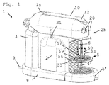
図1及び2は、本発明による飲料装置1の実施形態を示している。例えば、装置は、茶及び/又はコーヒーを調製及び注出するための装置である。
1 and 2 show an embodiment of a
装置1は、電気コード9を介して、通常は主要電源によって通電することができる。
The
装置1は、液体をリザーバ3から循環させるための内部回路を備えた飲料調製モジュールを有する。モジュールは、ハウジング2aによって覆われ、本体2を形成する脚部8を有する。ハウジング内の飲料調製モジュールは、風味付け原材料、特に、そのようなモジュールに供給される原材料等、カプセル内に事前に小分けされた原材料を保持し、液体をその中に循環させて飲料50を形成するように構成される。そのようなモジュールの例は、参照によって本明細書にその教示が組み込まれる、国際公開第2009/074550号パンフレット及び国際公開第2009/130099号パンフレットに開示される。
The
故に、例えば水等の液体がタンク3内に貯蔵され、タンク3から飲料調製モジュールに供給され得る。タンク又はリザーバ3のさらなる詳細は、例えば欧州特許第10163637.1号明細書に開示される。
Thus, a liquid such as water can be stored in the
飲料50は形成と同時に、注出領域5、5’、例えばユーザのカップ又はマグを保持するための支持体に出口4を介して注出することができる。注出領域は、図1に示すようなより小さいカップ51用の第1の支持体5を含むことができ、この第1の支持体5は、より大きいカップ又はマグ52のために、例えばルンゴ(lungo)又は特大量の飲料を注出するために、図2に示すように、より低い第2のカップ支持体5’にアクセス可能となるように出口4の下方から離れるように移動可能である。低い方のカップ支持体5’は、装置1の基部8に連結され得る。
Upon formation, the
装置1は、例えば使用済みカプセル内の茶葉又は挽いたコーヒー等の使用済み原材料及び廃水を収集するためのサービスユニット6を有する。サービスユニット6は、固体用の上側コンパートメント及び液体用の下側コンパートメントを含む収集器でもよい。サービスユニット6は、本体2内に形成された座部又は空洞60内に挿入可能、例えば摺動可能であり、サービスのために、例えば固体及び/又はユニット内に収容された液体を空にするためにそこから取り外し可能である。例えば、使用済み原材料用の収集器6の貯蔵能力は、例えば国際出願/欧州特許第10/056194号明細書で教示されたように、水等の液体の供給に関するリザーバ3の貯蔵能力に合わせることができる。
The
収集器6は、例えば重力によって、排出された使用済み風味付け原材料を飲料調製と同時に収集器6に収集するために飲料調製モジュールの下方に位置付けられ得る。収集器6は、通常、例えば参照によって本明細書に組み込まれる、国際公開第2009/074559号パンフレット及び国際公開第2009/135869号パンフレットに教示されるような詰まり防止装置を有する。
The
装置1はまた、例えば参照によって本明細書にその内容が組み込まれる欧州特許第10163638.9号明細書に教示されるように、出口4’に連結された、例えば発泡させたミルク及び/又は茶を調製するための蒸気及び/又は高温水の発生器も含む。
The
装置1は、例えばカプセル内の原材料をモジュール内に装填する及び/又はそのような原材料をモジュールから排出するための移送位置(図示せず)と、液体を原材料内に循環させるための(図1及び2に示す)循環位置との間で移動可能なハンドル10を有する。
The
通常、ハンドル10は、飲料調製モジュールの、抽出ユニット等の、原材料室を備えた原材料ホルダを、風味付け原材料をホルダ内に挿入し及び/又はホルダから排出するための移送位置と、液体を原材料ホルダ内のこの原材料内に循環させて飲料50を形成するための循環位置とから操作させる。原材料ホルダ、例えば抽出ユニットは2つの相対的に移動可能な部分を有し、これらの部分は、離されて原材料ホルダを移送位置へと開き、近付けられて原材料ホルダを循環位置へと閉じる。この循環位置では、原材料ホルダは、液体を原材料内で適切に案内することを確実にするために、風味付け原材料を緊密に封入することができる。適切な抽出ユニットの構成の例は、例えば欧州特許第1646305号明細書、欧州特許第1859713号明細書、欧州特許第1859714号明細書及び国際公開第2009/043630号パンフレットに開示されている。
Typically, the
循環位置(図1及び2)では、ハンドル10は、ハウジング2aの上面に又はその中に載置されている。特に先端部12を有するハンドル10は、例えば本体2の表面の洗浄を容易にするために、対応する形状を有するハウジング2aと同一面となることができる。
In the circulating position (FIGS. 1 and 2), the
ハンドル10は、人間工学的理由から、すなわちハンドル10が移送位置(図示せず)から循環位置まで移動されるときにユーザの手に接触する面を好都合に配置することによってハンドル10に力をかけることを容易にするために、その先端部12においてわずかに湾曲され又は曲げられた直線バーとして全体的に成形された単一アームレバーである。
The
移送位置では、ハンドル10は、例えばカプセル内の風味付け原材料を飲料調製モジュール内に挿入することを可能にするために通路を完全に露出させる。この原材料の挿入通路は、風味付け原材料を飲料調製モジュール内に重力によって導入するように配置することができ、操作部12は、例えばカプセル内の風味付け原材料の通路への手動による導入と、特に同じ手によるハンドル10の手動による操作との間の連携を容易にするために、ハンドル10が移送位置にあるときに、通路のほぼ上方に及び/又は隣接して位置している。
In the transfer position, the
ハンドル10及び原材料の取り扱いに関するさらなる詳細は、例えば欧州特許第10163649.6号明細書に開示される。
Further details regarding the handling of the
さらには、装置1は、飲料調製モジュール内で風味付け原材料内の液体の循環を開始するためのユーザインターフェース20を含む。ユーザインターフェース20は、さまざまな風味及び/又はさまざまなサイズ及び/さまざまなタイプの飲料の調製を開始するための複数のユーザセレクタを含むことができる。例えばユーザインターフェース20は、エスプレッソコーヒー及びルンゴコーヒーの注出を選択するための、例えばプッシュアンドターンボタンの形態の第1のユーザセレクタ及び第2のユーザセレクタを含む。装置1はまた、マスタースイッチ又はスチーム21を含むこともできる。
Furthermore, the
そのようなユーザセレクタに関するさらなる詳細は、欧州特許第10163635.5号明細書及び欧州特許第10163649.6号明細書に見出すことができる。 Further details regarding such user selectors can be found in EP 101636355.5 and EP 101633649.6.
飲料調製モジュールは通常、以下の構成要素のうち1つ又は複数を含む。
a)こうした飲料の風味付け原材料、特にカプセル内に供給される事前に小分けされた原材料を受け入れ、流入する水等の液体の流れをこの原材料を通して飲料出口4まで案内するための、抽出ユニット等の原材料ホルダ、
b)原材料ホルダに供給されて流入する液体の流れを加熱するための、サーモブロック等のインライン加熱器、
c)液体をインライン加熱器を通して圧送するためのポンプ、
d)液体を液体タンク3等の液体供給源から飲料出口4まで案内するための1つ又は複数の流体連結部材、
e)特に、インターフェースを介してユーザから指示を受け入れ、インライン加熱器及びポンプを制御するための印刷回路板(PCB)を備える、電気制御ユニット、及び
f)原材料ホルダ、インライン加熱器、ポンプ、液体リザーバ3、原材料収集器6、液体の流れ、液体の圧力、及び液体の温度の特性から選択された少なくとも1つの作動特性を感知し、そのような特性(複数可)を制御ユニットに通信するための1つ又は複数の電気センサ。
A beverage preparation module typically includes one or more of the following components.
a) such as an extraction unit for receiving such flavoring ingredients of beverages, in particular pre-divided ingredients supplied in capsules, and guiding the flow of liquid such as incoming water through the ingredients to the
b) An in-line heater, such as a thermoblock, for heating the flow of liquid fed into the raw material holder,
c) a pump for pumping liquid through an in-line heater;
d) one or more fluid coupling members for guiding the liquid from a liquid source such as the
e) Electrical control unit with printed circuit board (PCB) for receiving instructions from the user and controlling the inline heater and pump, in particular via the interface, and f) Raw material holder, inline heater, pump, liquid Sensing at least one operational characteristic selected from the characteristics of
加熱器は、サーモブロック又は瞬間加熱器(ODH)、例えば欧州特許第1253844号明細書、欧州特許第1380243号明細書及び欧州特許第1809151号明細書に開示されたODHタイプでもよい。適切な抽出ユニット及びカプセル管理の例は、例えば参照によって本明細書に組み込まれる、国際公開第2005/004683号パンフレット、国際公開第2007/135136号パンフレット、及び国際公開第2009/043630号パンフレットに開示される。適切な飲料調製モジュールは、例えば参照によって本明細書に組み込まれる、国際公開第2009/074550号パンフレット及び国際公開第2009/130099号パンフレットに開示される。 The heater may be a thermoblock or instantaneous heater (ODH), for example the ODH type disclosed in EP 1253844, EP 1380243 and EP 1809151. Examples of suitable extraction units and capsule management are disclosed in, for example, WO 2005/004683, WO 2007/135136, and WO 2009/043630, which are incorporated herein by reference. Is done. Suitable beverage preparation modules are disclosed, for example, in WO 2009/074550 and WO 2009/130099, which are incorporated herein by reference.
ハンドル10及びユーザインターフェース20は、ハンドル10を循環位置になるように操作した際、人の手がハンドル10の操作部12と接触している間も、その手によってユーザインターフェース20を操作可能であるように配置され得る。
When the
次に、図1及び図2に示す実施形態を、ユーザ容器支持体5及びサービス装置6、60に関連付けてより詳細に論じる。特に、支持体5は、サービスのためにサービス装置6、60へのユーザアクセスを可能にするロック解除位置(図2)と、サービスのためにサービス装置6、60へのユーザアクセスを妨げるロック位置(図1)とを有する。
The embodiment shown in FIGS. 1 and 2 will now be discussed in more detail in connection with the
サービス装置6、60は、本体2によって境界付けられた空洞60と、空洞60に出入するように移動可能であるサービスユニット6とを含む。図2は、わずかに傾けられ本体2内の空洞60から突出する、サービスユニット6、例えば収集器を示している。収集器6は、例えば、参照によってその教示が本明細書に組み込まれる国際公開第2009/135869号パンフレットで全体的に説明されるように詰まりを回避するために傾けることが可能にされ得る。
The
図1に示すように、支持体5は、サービスユニット6を収容する空洞60の前面開口部を、例えば、ほぼ水平に横切る等、ほぼ横切って延びることによって、サービスユニット6を空洞60内にロックする位置を有サービスする。支持体5のこの位置では、ユーザが、空洞60からサービスユニット6を取り外すこと、又はその前面開口部を介して空洞60にアクセスすることが阻まれる。
As shown in FIG. 1, the
図2では、支持体5は、サービスユニット6をロック解除する位置を有し、すなわちサービスユニット6は、空洞60から引き出され、支持体5との干渉無しに摺動して戻ることができる。特に、図2では、支持体5は、空洞6のこの前面開口部から離れた、例えばこの前面開口部の側部に隣接したほぼ垂直な位置にある。
In FIG. 2, the
図1及び2に示すように、ロック位置及びロック解除位置にある支持体5は、本体2に連結されており、サービスユニット6は、支持体5がロック解除位置にあるときに本体2及び支持体5から取り外し可能及び分離可能である。
As shown in FIGS. 1 and 2, the
或いは、ロック解除位置では支持体が、サービスユニットと共に取り外し可能になるようにユーザ容器支持体をサービスユニットに連結することが可能である。例えば、支持体は、サービスユニットに枢動的に連結され、1つ又は複数のフックを有し、このフックは、装置本体内の1つ又は複数のフック保持具によってロック位置で協働し、支持体がロック解除位置になるように枢動されたときにフック保持具(複数可)から解放される。 Alternatively, the user container support can be coupled to the service unit so that the support is removable with the service unit in the unlocked position. For example, the support is pivotally coupled to the service unit and has one or more hooks that cooperate in a locked position by one or more hook retainers in the device body, When the support is pivoted to the unlocked position, it is released from the hook holder (s).
図1及び2に示すように、支持体5は、サービス装置6、60に対してロック位置とロック解除位置の間で、特にロック位置からロック解除位置に、及び/又はその逆に回転可能である。特に、支持体5は、例えば、空洞60の前面開口部の側部に隣接して本体2から突出するほぼ水平な軸55を中心に回転可能である。
As shown in FIGS. 1 and 2, the
上記で述べたように、支持体5は、出口4から注出された飲料50を収集するために、通常はより少ない量の飲料を収集するために、出口4の下方で、より小さいユーザ容器51、例えばエスプレッソカップ等のカップを支持するための位置(図1)と、出口4から注出された飲料50を収集するために、通常はより多い量の飲料50を収集するために、出口4の下方で、より大きいユーザ容器52、例えばマグ又はより大きいカップを載置することを可能にするための位置(図2)とを有することができる。
As mentioned above, the
支持体5が、より大きいユーザ容器52用の位置にあるとき、出口4の下方でより大きいユーザ容器52のための載置面を露出させることができる。特にこの載置面は、例えば本体2に、特に本体2の基部8に連結された別の支持体5’によって形成され得る。
When the
変形形態では、載置面は、仮想面、例えば飲料調製装置が置かれるテーブルの表面であることができ、又はより小さいユーザ容器を支持するための位置より低い位置で同じ支持体によって形成することができる。後者の場合、支持体は、例えば空洞の前面開口部の側部に沿って垂直に摺動可能であり、垂直摺動は、例えば支持体のロック及び/又はロック解除機能に関連付けられる。 In a variant, the mounting surface can be a virtual surface, for example the surface of a table on which the beverage preparation device is placed, or formed by the same support at a position lower than the position for supporting a smaller user container. Can do. In the latter case, the support is slidable vertically, for example along the sides of the front opening of the cavity, and the vertical sliding is associated, for example, with the locking and / or unlocking function of the support.
図1及び2に示すように、より小さいユーザ容器51を支持するための支持体5の位置及びより大きいユーザ容器52の載置を可能にするための支持体5の位置は、それぞれ支持体のロック位置及びロック解除位置に相当する。
As shown in FIGS. 1 and 2, the position of the
通常、装置1は、飲料出口4を支える前面2bを有する。支持体5は、サービス装置6、60のサービスのためのサービス装置6、60への前面2bからのユーザアクセスを可能にするために、前面2bの周りで及び/又は前面から離れるように移動可能であり、サービスのためのサービス装置6、60へのユーザアクセスを妨げるために反対方向に移動可能であり得る。
Usually, the
特定の実施形態では、装置1は、出口4を支えるほぼ直立した前面2bと、出口4から飲料50を収集する位置でユーザ容器51を支持するための移動可能な支持体5とを有することができる。支持体5は、前面2bに対してほぼ垂直な軸55を中心に、例えばほぼ水平な軸を中心に回転可能である。支持体5は、支持体の回転中心をなす軸55に又は軸55に隣接して枢動端部56を有する。さらに装置1は、ストッパ58、例えば本体2から突出する要素を有し、支持体5は、ストッパ58に到達したときに、特に出口4の下方で小さいカップ51を支持するための支持体5の水平位置で支持体5の移動を停止させるストッパ58を阻止する阻止端部57を有する。この構成では、支持体5は、ストッパ58によって安全に保持され、重力下で安定する。特に、支持体5は、前面2bに対してほぼ平行に移動可能な縁59を有し、阻止端部57は、縁59上又は縁59に隣接して枢動端部56の反対側に位置する。
In a particular embodiment, the
Claims (15)
前記装置において、前記支持体が、サービスのために前記サービス装置へのユーザアクセスを可能にするロック解除位置と、サービスのために前記サービス装置へのユーザアクセスを妨げるロック位置とを有することを特徴とする、装置(1)。 A device (10) for dispensing said beverage comprising a service device (6, 60) and a movable support (5) for supporting the user container (51) in a position for collecting the beverage (50) 1)
In the device, the support has an unlocked position that allows user access to the service device for service and a lock position that prevents user access to the service device for service. The device (1).
前記支持体が前記本体(2)に接続され、前記支持体が前記ロック解除位置にあるときに、前記サービスユニット(6)が前記本体及び前記支持体から取り外し可能である、請求項3に記載の装置。 When the support is connected to the service unit and the support is in the unlocked position, the service unit is removable together with the support, or the support is attached to the main body (2). Device according to claim 3, wherein the service unit (6) is detachable from the body and the support when connected and the support is in the unlocked position.
前記飲料出口から注出される飲料(50)を収集するために前記飲料出口(4)下方でより小さいユーザ容器(51)を支持するための位置と、
前記飲料出口(4)から注出される飲料(50)を収集するために前記飲料出口(4)下方でより大きいユーザ容器(52)を載置することを可能にするための位置と
を有する、請求項1〜6のいずれか一項に記載の装置。 Having a beverage outlet (4), the support (5) being
A position for supporting a smaller user container (51) below the beverage outlet (4) to collect the beverage (50) dispensed from the beverage outlet;
A position for allowing a larger user container (52) to be placed under the beverage outlet (4) to collect the beverage (50) dispensed from the beverage outlet (4); Apparatus according to any one of claims 1-6.
前記支持体が、前記前面に対してほぼ垂直な軸(55)を中心に、特にほぼ水平な軸を中心に回転可能であることを特徴とする、装置(1)。 In particular, a device (1) for dispensing a beverage (50) comprising any feature or combination of features according to any one of claims 1 to 11, substantially supporting the outlet (4) In an apparatus comprising an upstanding front surface (2b) and a movable support (5) for supporting a user container (51) in a position to collect beverage from the outlet,
Device (1), characterized in that the support is rotatable about an axis (55) substantially perpendicular to the front surface, in particular about an axis substantially horizontal.
Applications Claiming Priority (3)
| Application Number | Priority Date | Filing Date | Title |
|---|---|---|---|
| EP10165365.7 | 2010-06-09 | ||
| EP10165365 | 2010-06-09 | ||
| PCT/EP2011/059580 WO2011154492A1 (en) | 2010-06-09 | 2011-06-09 | Ergonomic service arrangement for beverage machine |
Publications (2)
| Publication Number | Publication Date |
|---|---|
| JP2013529121A true JP2013529121A (en) | 2013-07-18 |
| JP2013529121A5 JP2013529121A5 (en) | 2014-07-24 |
Family
ID=43824537
Family Applications (1)
| Application Number | Title | Priority Date | Filing Date |
|---|---|---|---|
| JP2013513696A Pending JP2013529121A (en) | 2010-06-09 | 2011-06-09 | Ergonomic service equipment for beverage equipment |
Country Status (12)
| Country | Link |
|---|---|
| US (1) | US8839832B2 (en) |
| EP (1) | EP2579754B1 (en) |
| JP (1) | JP2013529121A (en) |
| CN (1) | CN102946773B (en) |
| AU (1) | AU2011263725B2 (en) |
| BR (1) | BR112012031401A2 (en) |
| CA (1) | CA2801278A1 (en) |
| ES (1) | ES2561669T3 (en) |
| PT (1) | PT2579754E (en) |
| RU (1) | RU2563214C2 (en) |
| WO (1) | WO2011154492A1 (en) |
| ZA (1) | ZA201300181B (en) |
Families Citing this family (46)
| Publication number | Priority date | Publication date | Assignee | Title |
|---|---|---|---|---|
| CN103002783B (en) | 2010-07-12 | 2016-08-17 | 雀巢产品技术援助有限公司 | Firm cup supporting member for beverage machine |
| US9675205B2 (en) | 2012-01-13 | 2017-06-13 | Nestec S.A. | Beverage machine for short and tall cups |
| ITMI20130724A1 (en) * | 2013-05-03 | 2014-11-04 | De Longhi Appliances Srl | EXECUTED COFFEE COLLECTOR FOR COFFEE MACHINE AND COFFEE MACHINE THAT INCORPORATES SUCH A COLLECTOR |
| PT107496B (en) | 2014-03-05 | 2021-03-11 | Novadelta - Comércio E Indústria De Cafés, Lda. | SUPPORT FOR DRINK PREPARATION MACHINE CONTAINERS AND METHOD OF USE OF THE REFERRED SUPPORT FOR CONTAINERS |
| ES2757601T3 (en) | 2014-07-09 | 2020-04-29 | Nestle Sa | Device to connect a beverage machine to a distribution network with security monitoring |
| EP3166458B1 (en) | 2014-07-09 | 2021-05-05 | Société des Produits Nestlé S.A. | Coupling of a device for connecting a beverage machine to a distribution network |
| WO2016005349A1 (en) | 2014-07-09 | 2016-01-14 | Nestec S.A. | Accessory for supplying automatically a beverage machine with liquid from a distribution network |
| EP3166455B1 (en) | 2014-07-09 | 2020-09-30 | Société des Produits Nestlé S.A. | Device for connecting a beverage machine to a distribution network with safe flow interruption |
| WO2016083488A1 (en) | 2014-11-27 | 2016-06-02 | Nestec S.A. | Liquid dispensing machine with compact drop stop |
| CN106998941B (en) | 2014-11-27 | 2020-12-01 | 雀巢产品有限公司 | Liquid dispensing machine with manual drop stop |
| WO2016083484A1 (en) | 2014-11-27 | 2016-06-02 | Nestec S.A. | Ergonomic handle arrangement |
| USD801112S1 (en) * | 2015-01-19 | 2017-10-31 | Ascendo Medienagentur Ag | Beverage machine |
| US9844293B2 (en) | 2015-03-06 | 2017-12-19 | Spectrum Brands, Inc. | Apparatus for dispensing beverages |
| EP3277135B1 (en) * | 2015-04-02 | 2024-01-03 | Société des Produits Nestlé S.A. | Shallow machine |
| WO2017062282A1 (en) * | 2015-10-05 | 2017-04-13 | Grindmaster Corporation | Beverage brewer with adjustable shelf |
| EP3373779B1 (en) | 2015-11-11 | 2020-12-23 | Société des Produits Nestlé S.A. | Easy connection of a liquid tank to a beverage machine |
| US10939780B2 (en) | 2016-03-17 | 2021-03-09 | Eugster / Frismag Ag | Beverage preparation device and operating method |
| ITUA20163118A1 (en) * | 2016-05-03 | 2017-11-03 | Water Time Il Boccione S R L | AUTOMATIC DISTRIBUTOR OF BEVERAGES EXPRESSED WITH PAYMENT |
| JP7364464B2 (en) | 2016-09-09 | 2023-10-18 | ソシエテ・デ・プロデュイ・ネスレ・エス・アー | Beverage machine with ergonomic handling part |
| US11234553B2 (en) | 2016-10-11 | 2022-02-01 | Societe Des Produits Nestle S.A. | Liquid dispensing machine with speed regulator |
| WO2018069266A1 (en) | 2016-10-11 | 2018-04-19 | Nestec Sa | Liquid dispensing machine with drop stop |
| EP3589175B1 (en) | 2017-02-28 | 2023-08-23 | Société des Produits Nestlé S.A. | Dispenser with parallel dispensing paths |
| WO2018219989A1 (en) | 2017-06-01 | 2018-12-06 | Nestec Sa | Beverage machine with a stablizing foot |
| US20200129002A1 (en) | 2017-06-01 | 2020-04-30 | Societe Des Produits Nestle S.A. | Beverage machine with a storable dispensing head |
| EP3629858A1 (en) | 2017-06-01 | 2020-04-08 | Société des Produits Nestlé S.A. | Beverage machine with ergonomic power switch |
| EP3629853A1 (en) | 2017-06-01 | 2020-04-08 | Société des Produits Nestlé S.A. | Beverage machine with a collapsible interface |
| DK3638085T3 (en) | 2017-06-13 | 2021-03-29 | Nestle Sa | BEVERAGE PREPARATION MACHINE WITH Capsule RECOGNITION |
| ES2956783T3 (en) | 2017-09-25 | 2023-12-28 | Nestle Sa | Beverage machines with removable module |
| WO2019057619A1 (en) | 2017-09-25 | 2019-03-28 | Nestec Sa | Beverage machines with modularity |
| US11564527B2 (en) | 2017-12-20 | 2023-01-31 | Societe Des Produits Nestle S.A. | Beverage preparation machine with drop evacuation |
| CA3086094A1 (en) | 2017-12-20 | 2019-06-27 | Societe Des Produits Nestle S.A. | Beverage preparation machine with handy drop stop |
| CA3086319A1 (en) | 2017-12-20 | 2019-06-27 | Societe Des Produits Nestle S.A. | Beverage preparation machine with foam refinement |
| US20200397184A1 (en) | 2018-02-09 | 2020-12-24 | Societe Des Produits Nestle S,A. | Beverage preparation machine with capsule recognition |
| EP3764855A1 (en) | 2018-03-14 | 2021-01-20 | Société des Produits Nestlé S.A. | Beverage machine with a partly closed dispensing face |
| US11363907B2 (en) | 2018-03-14 | 2022-06-21 | Societe Des Produits Nestle S.A. | Beverage machine with a controlled capsule piercing |
| WO2019175228A1 (en) | 2018-03-14 | 2019-09-19 | Societe Des Produits Nestle S.A. | Beverage machine with a controlled outflow aperture |
| CN111801035B (en) | 2018-03-14 | 2023-04-21 | 雀巢产品有限公司 | Beverage machine with partially open dispensing face |
| CN112512390B (en) | 2018-08-09 | 2023-08-25 | 雀巢产品有限公司 | Cup support easy to insert |
| EP4248808A3 (en) | 2018-09-27 | 2023-10-04 | Société des Produits Nestlé S.A. | Beverage machine with an actuation distribution |
| WO2020064982A1 (en) | 2018-09-27 | 2020-04-02 | Société des Produits Nestlé SA | Adaptive service unit of a beverage machine |
| EP3628195A1 (en) | 2018-09-27 | 2020-04-01 | Société des Produits Nestlé S.A. | Beverage preparation machine with recipient detection |
| US20220053967A1 (en) | 2018-12-12 | 2022-02-24 | Societe Des Produits Nestle S.A. | Beverage preparation machine with capsule recognition |
| CN115003199A (en) | 2020-02-05 | 2022-09-02 | 雀巢产品有限公司 | Beverage preparation machine with capsule recognition |
| EP4099875A1 (en) | 2020-02-05 | 2022-12-14 | Société des Produits Nestlé S.A. | Beverage preparation machine with capsule recognition |
| CA3231859A1 (en) | 2021-10-08 | 2023-04-13 | Societe Des Produits Nestle S.A. | Beverage preparation machine with simple ergonomic opening-closure |
| CA3233465A1 (en) | 2021-10-13 | 2023-04-20 | Laurent LAGOUCHE | Ergonomic beverage machine |
Citations (6)
| Publication number | Priority date | Publication date | Assignee | Title |
|---|---|---|---|---|
| JPS5015462U (en) * | 1973-06-06 | 1975-02-18 | ||
| JPH0975224A (en) * | 1995-09-08 | 1997-03-25 | Sanyo Electric Co Ltd | Beverage supply device |
| JPH11169295A (en) * | 1997-12-16 | 1999-06-29 | Hoshizaki Electric Co Ltd | Tea server |
| JP2003054697A (en) * | 2001-08-07 | 2003-02-26 | Sanyo Electric Co Ltd | Cup type drink supply apparatus |
| US20080148950A1 (en) * | 2006-06-16 | 2008-06-26 | Antoine Cahen | Drink dispensing device with holding and drip-collecting system for receptacles of different sizes |
| WO2009074559A1 (en) * | 2007-12-12 | 2009-06-18 | Nestec S.A. | Used capsule or pod receptacle for liquid food or beverage machines |
Family Cites Families (19)
| Publication number | Priority date | Publication date | Assignee | Title |
|---|---|---|---|---|
| US5161455A (en) | 1991-05-15 | 1992-11-10 | Bunn-O-Matic Corporation | Combination coffee and tea brewer |
| IT1252633B (en) | 1991-12-05 | 1995-06-19 | Gianmauro Zani | COMPACT COFFEE MACHINE FOR ESPRESSO COFFEE AND HOT WATER FALL COFFEE FOR FILTRATION OTHERWISE KNOWN AS AMERICAN COFFEE. |
| US5353692A (en) | 1993-09-29 | 1994-10-11 | Unidynamics Corporation | Hot beverage brewing apparatus |
| US6459854B1 (en) | 2000-01-24 | 2002-10-01 | Nestec S.A. | Process and module for heating liquid |
| EP1380243B1 (en) | 2002-07-12 | 2008-06-25 | Nestec S.A. | A device for the heating of a liquid |
| GB2397503B (en) | 2003-01-24 | 2005-03-02 | Kraft Foods R & D Inc | Machine for the preparation of beverages |
| EP1495702A1 (en) | 2003-07-10 | 2005-01-12 | Nestec S.A. | Device for the extraction of a cartridge |
| EP1634520A1 (en) | 2004-09-13 | 2006-03-15 | Nestec S.A. | Device and method for heating a liquid |
| ATE421273T1 (en) * | 2004-09-24 | 2009-02-15 | Saeco Ipr Ltd | COFFEE MACHINE WITH A HEIGHT-ADJUSTABLE COLLECTION TRAY |
| DE602004031632D1 (en) | 2004-11-11 | 2011-04-14 | Nestec Sa | Self-cleaning mixing head for milk drinks and machines with such a mixing head |
| PL1731065T3 (en) | 2005-06-07 | 2008-11-28 | Nestec Sa | Beverage machine with drip tray device for recipients of different heights |
| DK1859714T3 (en) | 2006-05-24 | 2009-05-25 | Nestec Sa | Brewing device and brewing system with a capsule holder for easy insertion and removal of capsules |
| PL1859713T3 (en) | 2006-05-24 | 2010-02-26 | Nestec Sa | Brewing device for capsule with closure mechanism of variable transmission ratio |
| GB2449307B (en) * | 2007-05-18 | 2011-09-28 | Kraft Foods R & D Inc | Improvements in or relating to beverage preparation machines |
| AU2008306060C1 (en) | 2007-10-04 | 2015-08-27 | Société des Produits Nestlé S.A. | Beverage brewing unit |
| EP2070454B1 (en) | 2007-12-12 | 2015-07-15 | Nestec S.A. | Beverage production machines comprising a plurality of core units |
| JP2011518015A (en) | 2008-04-22 | 2011-06-23 | ネステク ソシエテ アノニム | Module assembly for beverage production equipment |
| US8695484B2 (en) | 2008-05-07 | 2014-04-15 | Nestec S.A. | Used capsule collector for beverage devices |
| DE102008042177A1 (en) | 2008-09-17 | 2010-03-25 | BSH Bosch und Siemens Hausgeräte GmbH | Vending Machine |
-
2011
- 2011-06-09 CN CN201180028485.XA patent/CN102946773B/en active Active
- 2011-06-09 US US13/702,651 patent/US8839832B2/en active Active
- 2011-06-09 CA CA2801278A patent/CA2801278A1/en not_active Abandoned
- 2011-06-09 AU AU2011263725A patent/AU2011263725B2/en not_active Ceased
- 2011-06-09 WO PCT/EP2011/059580 patent/WO2011154492A1/en active Application Filing
- 2011-06-09 RU RU2012157555/12A patent/RU2563214C2/en not_active IP Right Cessation
- 2011-06-09 BR BR112012031401A patent/BR112012031401A2/en not_active IP Right Cessation
- 2011-06-09 PT PT117261040T patent/PT2579754E/en unknown
- 2011-06-09 JP JP2013513696A patent/JP2013529121A/en active Pending
- 2011-06-09 ES ES11726104.0T patent/ES2561669T3/en active Active
- 2011-06-09 EP EP11726104.0A patent/EP2579754B1/en active Active
-
2013
- 2013-01-08 ZA ZA2013/00181A patent/ZA201300181B/en unknown
Patent Citations (6)
| Publication number | Priority date | Publication date | Assignee | Title |
|---|---|---|---|---|
| JPS5015462U (en) * | 1973-06-06 | 1975-02-18 | ||
| JPH0975224A (en) * | 1995-09-08 | 1997-03-25 | Sanyo Electric Co Ltd | Beverage supply device |
| JPH11169295A (en) * | 1997-12-16 | 1999-06-29 | Hoshizaki Electric Co Ltd | Tea server |
| JP2003054697A (en) * | 2001-08-07 | 2003-02-26 | Sanyo Electric Co Ltd | Cup type drink supply apparatus |
| US20080148950A1 (en) * | 2006-06-16 | 2008-06-26 | Antoine Cahen | Drink dispensing device with holding and drip-collecting system for receptacles of different sizes |
| WO2009074559A1 (en) * | 2007-12-12 | 2009-06-18 | Nestec S.A. | Used capsule or pod receptacle for liquid food or beverage machines |
Also Published As
| Publication number | Publication date |
|---|---|
| ES2561669T3 (en) | 2016-02-29 |
| PT2579754E (en) | 2016-03-04 |
| CN102946773A (en) | 2013-02-27 |
| RU2563214C2 (en) | 2015-09-20 |
| US20130081739A1 (en) | 2013-04-04 |
| WO2011154492A1 (en) | 2011-12-15 |
| AU2011263725B2 (en) | 2015-04-09 |
| EP2579754B1 (en) | 2016-01-06 |
| CN102946773B (en) | 2018-06-15 |
| ZA201300181B (en) | 2014-06-25 |
| EP2579754A1 (en) | 2013-04-17 |
| AU2011263725A1 (en) | 2012-12-20 |
| US8839832B2 (en) | 2014-09-23 |
| RU2012157555A (en) | 2014-07-20 |
| BR112012031401A2 (en) | 2016-11-08 |
| CA2801278A1 (en) | 2011-12-15 |
Similar Documents
| Publication | Publication Date | Title |
|---|---|---|
| JP2013529121A (en) | Ergonomic service equipment for beverage equipment | |
| EP2592980B1 (en) | Secure cup support for beverage machine | |
| AU2013208992B2 (en) | Beverage machine for short and tall cups | |
| US9795247B2 (en) | Beverage machine with a handy outlet | |
| JP2013544172A (en) | Beverage preparation device with droplet collector | |
| JP2013517026A (en) | Cooperation between ergonomic raw material holder and service unit | |
| JP2011505937A (en) | Used capsule or pod container for liquid food or beverage preparation equipment | |
| RU2557492C2 (en) | Device for supply of hot water or water steam with storage position | |
| CN111655092A (en) | Used capsule receptacle for beverage machine | |
| JP2013526358A5 (en) | ||
| CN110313831B (en) | Beverage preparation machine | |
| JP7382398B2 (en) | Beverage machine adaptive service unit |
Legal Events
| Date | Code | Title | Description |
|---|---|---|---|
| A521 | Request for written amendment filed |
Free format text: JAPANESE INTERMEDIATE CODE: A523 Effective date: 20140604 |
|
| A621 | Written request for application examination |
Free format text: JAPANESE INTERMEDIATE CODE: A621 Effective date: 20140604 |
|
| A977 | Report on retrieval |
Free format text: JAPANESE INTERMEDIATE CODE: A971007 Effective date: 20150525 |
|
| A131 | Notification of reasons for refusal |
Free format text: JAPANESE INTERMEDIATE CODE: A131 Effective date: 20150602 |
|
| A02 | Decision of refusal |
Free format text: JAPANESE INTERMEDIATE CODE: A02 Effective date: 20151110 |