JP2013526942A - System and method for measuring reduced pressure using an isolated fluid flow path - Google Patents
System and method for measuring reduced pressure using an isolated fluid flow path Download PDFInfo
- Publication number
- JP2013526942A JP2013526942A JP2013511306A JP2013511306A JP2013526942A JP 2013526942 A JP2013526942 A JP 2013526942A JP 2013511306 A JP2013511306 A JP 2013511306A JP 2013511306 A JP2013511306 A JP 2013511306A JP 2013526942 A JP2013526942 A JP 2013526942A
- Authority
- JP
- Japan
- Prior art keywords
- reduced pressure
- movable part
- diaphragm
- evaluation
- pressure detector
- Prior art date
- Legal status (The legal status is an assumption and is not a legal conclusion. Google has not performed a legal analysis and makes no representation as to the accuracy of the status listed.)
- Withdrawn
Links
Images


Classifications
-
- A—HUMAN NECESSITIES
- A61—MEDICAL OR VETERINARY SCIENCE; HYGIENE
- A61M—DEVICES FOR INTRODUCING MEDIA INTO, OR ONTO, THE BODY; DEVICES FOR TRANSDUCING BODY MEDIA OR FOR TAKING MEDIA FROM THE BODY; DEVICES FOR PRODUCING OR ENDING SLEEP OR STUPOR
- A61M1/00—Suction or pumping devices for medical purposes; Devices for carrying-off, for treatment of, or for carrying-over, body-liquids; Drainage systems
- A61M1/60—Containers for suction drainage, adapted to be used with an external suction source
- A61M1/63—Containers for suction drainage, adapted to be used with an external suction source with means for emptying the suction container, e.g. by interrupting suction
-
- A—HUMAN NECESSITIES
- A61—MEDICAL OR VETERINARY SCIENCE; HYGIENE
- A61M—DEVICES FOR INTRODUCING MEDIA INTO, OR ONTO, THE BODY; DEVICES FOR TRANSDUCING BODY MEDIA OR FOR TAKING MEDIA FROM THE BODY; DEVICES FOR PRODUCING OR ENDING SLEEP OR STUPOR
- A61M1/00—Suction or pumping devices for medical purposes; Devices for carrying-off, for treatment of, or for carrying-over, body-liquids; Drainage systems
- A61M1/71—Suction drainage systems
- A61M1/73—Suction drainage systems comprising sensors or indicators for physical values
- A61M1/732—Visual indicating means for vacuum pressure
-
- A—HUMAN NECESSITIES
- A61—MEDICAL OR VETERINARY SCIENCE; HYGIENE
- A61M—DEVICES FOR INTRODUCING MEDIA INTO, OR ONTO, THE BODY; DEVICES FOR TRANSDUCING BODY MEDIA OR FOR TAKING MEDIA FROM THE BODY; DEVICES FOR PRODUCING OR ENDING SLEEP OR STUPOR
- A61M1/00—Suction or pumping devices for medical purposes; Devices for carrying-off, for treatment of, or for carrying-over, body-liquids; Drainage systems
- A61M1/80—Suction pumps
- A61M1/82—Membrane pumps, e.g. bulbs
-
- A—HUMAN NECESSITIES
- A61—MEDICAL OR VETERINARY SCIENCE; HYGIENE
- A61M—DEVICES FOR INTRODUCING MEDIA INTO, OR ONTO, THE BODY; DEVICES FOR TRANSDUCING BODY MEDIA OR FOR TAKING MEDIA FROM THE BODY; DEVICES FOR PRODUCING OR ENDING SLEEP OR STUPOR
- A61M1/00—Suction or pumping devices for medical purposes; Devices for carrying-off, for treatment of, or for carrying-over, body-liquids; Drainage systems
- A61M1/90—Negative pressure wound therapy devices, i.e. devices for applying suction to a wound to promote healing, e.g. including a vacuum dressing
- A61M1/96—Suction control thereof
- A61M1/966—Suction control thereof having a pressure sensor on or near the dressing
-
- A—HUMAN NECESSITIES
- A61—MEDICAL OR VETERINARY SCIENCE; HYGIENE
- A61M—DEVICES FOR INTRODUCING MEDIA INTO, OR ONTO, THE BODY; DEVICES FOR TRANSDUCING BODY MEDIA OR FOR TAKING MEDIA FROM THE BODY; DEVICES FOR PRODUCING OR ENDING SLEEP OR STUPOR
- A61M1/00—Suction or pumping devices for medical purposes; Devices for carrying-off, for treatment of, or for carrying-over, body-liquids; Drainage systems
- A61M1/71—Suction drainage systems
- A61M1/74—Suction control
-
- A—HUMAN NECESSITIES
- A61—MEDICAL OR VETERINARY SCIENCE; HYGIENE
- A61M—DEVICES FOR INTRODUCING MEDIA INTO, OR ONTO, THE BODY; DEVICES FOR TRANSDUCING BODY MEDIA OR FOR TAKING MEDIA FROM THE BODY; DEVICES FOR PRODUCING OR ENDING SLEEP OR STUPOR
- A61M1/00—Suction or pumping devices for medical purposes; Devices for carrying-off, for treatment of, or for carrying-over, body-liquids; Drainage systems
- A61M1/90—Negative pressure wound therapy devices, i.e. devices for applying suction to a wound to promote healing, e.g. including a vacuum dressing
- A61M1/91—Suction aspects of the dressing
- A61M1/912—Connectors between dressing and drainage tube
-
- A—HUMAN NECESSITIES
- A61—MEDICAL OR VETERINARY SCIENCE; HYGIENE
- A61M—DEVICES FOR INTRODUCING MEDIA INTO, OR ONTO, THE BODY; DEVICES FOR TRANSDUCING BODY MEDIA OR FOR TAKING MEDIA FROM THE BODY; DEVICES FOR PRODUCING OR ENDING SLEEP OR STUPOR
- A61M1/00—Suction or pumping devices for medical purposes; Devices for carrying-off, for treatment of, or for carrying-over, body-liquids; Drainage systems
- A61M1/90—Negative pressure wound therapy devices, i.e. devices for applying suction to a wound to promote healing, e.g. including a vacuum dressing
- A61M1/96—Suction control thereof
-
- A—HUMAN NECESSITIES
- A61—MEDICAL OR VETERINARY SCIENCE; HYGIENE
- A61M—DEVICES FOR INTRODUCING MEDIA INTO, OR ONTO, THE BODY; DEVICES FOR TRANSDUCING BODY MEDIA OR FOR TAKING MEDIA FROM THE BODY; DEVICES FOR PRODUCING OR ENDING SLEEP OR STUPOR
- A61M2205/00—General characteristics of the apparatus
- A61M2205/27—General characteristics of the apparatus preventing use
- A61M2205/273—General characteristics of the apparatus preventing use preventing reuse, e.g. of disposables
-
- A—HUMAN NECESSITIES
- A61—MEDICAL OR VETERINARY SCIENCE; HYGIENE
- A61M—DEVICES FOR INTRODUCING MEDIA INTO, OR ONTO, THE BODY; DEVICES FOR TRANSDUCING BODY MEDIA OR FOR TAKING MEDIA FROM THE BODY; DEVICES FOR PRODUCING OR ENDING SLEEP OR STUPOR
- A61M2205/00—General characteristics of the apparatus
- A61M2205/33—Controlling, regulating or measuring
- A61M2205/3306—Optical measuring means
-
- A—HUMAN NECESSITIES
- A61—MEDICAL OR VETERINARY SCIENCE; HYGIENE
- A61M—DEVICES FOR INTRODUCING MEDIA INTO, OR ONTO, THE BODY; DEVICES FOR TRANSDUCING BODY MEDIA OR FOR TAKING MEDIA FROM THE BODY; DEVICES FOR PRODUCING OR ENDING SLEEP OR STUPOR
- A61M2205/00—General characteristics of the apparatus
- A61M2205/33—Controlling, regulating or measuring
- A61M2205/3317—Electromagnetic, inductive or dielectric measuring means
-
- A—HUMAN NECESSITIES
- A61—MEDICAL OR VETERINARY SCIENCE; HYGIENE
- A61M—DEVICES FOR INTRODUCING MEDIA INTO, OR ONTO, THE BODY; DEVICES FOR TRANSDUCING BODY MEDIA OR FOR TAKING MEDIA FROM THE BODY; DEVICES FOR PRODUCING OR ENDING SLEEP OR STUPOR
- A61M2205/00—General characteristics of the apparatus
- A61M2205/33—Controlling, regulating or measuring
- A61M2205/3331—Pressure; Flow
- A61M2205/3344—Measuring or controlling pressure at the body treatment site
-
- A—HUMAN NECESSITIES
- A61—MEDICAL OR VETERINARY SCIENCE; HYGIENE
- A61M—DEVICES FOR INTRODUCING MEDIA INTO, OR ONTO, THE BODY; DEVICES FOR TRANSDUCING BODY MEDIA OR FOR TAKING MEDIA FROM THE BODY; DEVICES FOR PRODUCING OR ENDING SLEEP OR STUPOR
- A61M2205/00—General characteristics of the apparatus
- A61M2205/82—Internal energy supply devices
- A61M2205/8206—Internal energy supply devices battery-operated
-
- A—HUMAN NECESSITIES
- A61—MEDICAL OR VETERINARY SCIENCE; HYGIENE
- A61M—DEVICES FOR INTRODUCING MEDIA INTO, OR ONTO, THE BODY; DEVICES FOR TRANSDUCING BODY MEDIA OR FOR TAKING MEDIA FROM THE BODY; DEVICES FOR PRODUCING OR ENDING SLEEP OR STUPOR
- A61M2205/00—General characteristics of the apparatus
- A61M2205/84—General characteristics of the apparatus for treating several patients simultaneously
-
- A—HUMAN NECESSITIES
- A61—MEDICAL OR VETERINARY SCIENCE; HYGIENE
- A61M—DEVICES FOR INTRODUCING MEDIA INTO, OR ONTO, THE BODY; DEVICES FOR TRANSDUCING BODY MEDIA OR FOR TAKING MEDIA FROM THE BODY; DEVICES FOR PRODUCING OR ENDING SLEEP OR STUPOR
- A61M2209/00—Ancillary equipment
- A61M2209/06—Packaging for specific medical equipment
-
- A—HUMAN NECESSITIES
- A61—MEDICAL OR VETERINARY SCIENCE; HYGIENE
- A61M—DEVICES FOR INTRODUCING MEDIA INTO, OR ONTO, THE BODY; DEVICES FOR TRANSDUCING BODY MEDIA OR FOR TAKING MEDIA FROM THE BODY; DEVICES FOR PRODUCING OR ENDING SLEEP OR STUPOR
- A61M2209/00—Ancillary equipment
- A61M2209/08—Supports for equipment
- A61M2209/084—Supporting bases, stands for equipment
- A61M2209/086—Docking stations
-
- Y—GENERAL TAGGING OF NEW TECHNOLOGICAL DEVELOPMENTS; GENERAL TAGGING OF CROSS-SECTIONAL TECHNOLOGIES SPANNING OVER SEVERAL SECTIONS OF THE IPC; TECHNICAL SUBJECTS COVERED BY FORMER USPC CROSS-REFERENCE ART COLLECTIONS [XRACs] AND DIGESTS
- Y10—TECHNICAL SUBJECTS COVERED BY FORMER USPC
- Y10T—TECHNICAL SUBJECTS COVERED BY FORMER US CLASSIFICATION
- Y10T137/00—Fluid handling
- Y10T137/0318—Processes
- Y10T137/0402—Cleaning, repairing, or assembling
Abstract
組織部位における減圧の評価を提供するシステム、装置、および方法が提示される。システム、装置、および方法は、圧力検出器とは流体的に隔離されている評価室を含む。他のシステム、方法、および装置が提示されている。
【選択図】図1Systems, devices, and methods are provided that provide an assessment of reduced pressure at a tissue site. The system, apparatus, and method include an evaluation chamber that is fluidly isolated from the pressure detector. Other systems, methods, and apparatus are presented.
[Selection] Figure 1
Description
関連出願の相互参照
本発明は、35USC§119(e)下において、2010年5月18日出願の米国仮特許出願第61/345,830号(「Systems and Methods for Measuring Reduced Pressure Employing An Isolated Fluid Path」と題される)(あらゆる点において本願明細書に援用する);2010年5月18日出願の米国仮特許出願第61/345,821号(「Reduced−Pressure Treatment Systems and Methods Employing A Fluidly Isolated Pump Control Unit」と題される)(あらゆる点において本願明細書に援用する);および2010年11月17日出願の米国仮特許出願第61/414,738号(「Reduced−Pressure Canisters and Methods for Recycling」と題される)(あらゆる点において本願明細書に援用する)の利益を主張する。
CROSS REFERENCE TO RELATED APPLICATIONS The present invention is under 35 USC §119 (e), US Provisional Patent Application No. 61 / 345,830, filed May 18, 2010 ("Systems and Methods for Measuring Reduced Pressure Employing An Isolated Fluid). (Incorporated herein in all respects); US Provisional Patent Application No. 61 / 345,821, filed May 18, 2010 ("Reduce-Pressure Treatment Systems and Methods Employing A Fluidly"). "Isolated Pump Control Unit") (incorporated herein in all respects); and November 17, 2010 Claims the benefit of US Provisional Patent Application No. 61 / 414,738 (titled “Reduce-Pressure Canisters and Methods for Recycling”), which is incorporated herein in all respects.
本開示は、概して減圧治療システムに関し、より詳細には、限定されるものではないが、隔離された流体流路を用いる、減圧を測定するためのシステムおよび方法に関する。 The present disclosure relates generally to reduced pressure treatment systems and, more particularly, to a system and method for measuring reduced pressure using, but not limited to, an isolated fluid flow path.
臨床試験および実習において、組織部位に近接して減圧をもたらすことによって、組織部位における新しい組織の生成を増強および加速することが示されている。この現象の適用は多数あるが、減圧を行うことは創傷の治療においてかなり成功している。この治療(医学界では「陰圧閉鎖療法」、「減圧療法」、または「真空療法」と呼ばれることが多い)は、いくつもの利点を提供し、それら利点には、迅速な治癒や肉芽組織の形成加速化が含まれ得る。一般に、減圧は、多孔質パッドまたは他のマニホールド装置を通して組織に加えられる。多孔質パッドはセルや細孔を含み、それらセルや細孔は、減圧を組織に分配し、および組織から引き出された流体を導くことができる。時には、組織部位に関わる減圧を決定することを望ましいとし得る。例えば、減圧が治療域内にあることを確かめることを望ましいとし得る。 In clinical trials and practice, it has been shown to increase and accelerate the generation of new tissue at a tissue site by providing a reduced pressure in proximity to the tissue site. Although there are many applications of this phenomenon, performing decompression has been quite successful in treating wounds. This treatment (often referred to in the medical community as “negative pressure closure therapy”, “decompression therapy”, or “vacuum therapy”) offers a number of benefits, including rapid healing and granulation tissue Acceleration of formation can be included. Generally, reduced pressure is applied to the tissue through a porous pad or other manifold device. The porous pad includes cells and pores that can distribute reduced pressure to the tissue and direct fluid drawn from the tissue. Sometimes it may be desirable to determine the reduced pressure associated with a tissue site. For example, it may be desirable to verify that the reduced pressure is within the treatment area.
説明に役立つ非限定的な実施形態によれば、減圧を用いて患者の組織部位を治療するシステムは、組織部位に近接して展開配置するための治療マニホールドと、患者の表皮の一部分および治療マニホールドを覆って流体シールを形成するシール部材と、減圧をもたらす減圧源と、治療マニホールドおよび減圧源に流体結合する減圧供給導管とを含む。減圧供給導管は、治療マニホールドに治療用減圧を供給するためのものである。システムは、組織部位および評価室に流体結合する減圧評価導管をさらに含む。評価室は、減圧評価導管に流体結合し、および組織部位から評価用減圧を受け取るためのものである。評価室は、壁に第1の可動部分を有する密封されたエンクロージャを含む。第1の可動部分は、減圧の影響を受けて動くように動作可能である。システムはまた、評価室の第1の可動部分に近接して第1の圧力検出器を含む。第1の圧力検出器は、評価室とは流体的に隔離されており、および第1の可動部分の変位を感知するように動作可能である。 According to an illustrative non-limiting embodiment, a system for treating a patient tissue site using reduced pressure includes a treatment manifold for deployment in proximity to the tissue site, a portion of the patient's epidermis, and a treatment manifold. And a reduced pressure source for providing reduced pressure, and a reduced pressure supply conduit fluidly coupled to the treatment manifold and the reduced pressure source. The reduced pressure supply conduit is for supplying a therapeutic reduced pressure to the treatment manifold. The system further includes a reduced pressure evaluation conduit that fluidly couples to the tissue site and the evaluation chamber. The evaluation chamber is for fluidly coupling to the reduced pressure evaluation conduit and for receiving an evaluation reduced pressure from the tissue site. The evaluation chamber includes a sealed enclosure having a first movable part on the wall. The first movable part is operable to move under the influence of reduced pressure. The system also includes a first pressure detector proximate to the first movable part of the evaluation chamber. The first pressure detector is fluidly isolated from the evaluation chamber and is operable to sense displacement of the first movable part.
説明に役立つ別の非限定的な実施形態によれば、減圧を用いる患者の組織部位の治療方法は、組織部位に近接させて治療マニホールドを配置するステップと、患者の表皮の一部分および治療マニホールドを覆ってシール部材を配置し、流体シールを形成するステップと、減圧源を設けるステップと、治療マニホールドおよび減圧源に減圧供給導管を流体結合するステップと、評価室を設けるステップと、評価室と組織部位に減圧評価導管を流体結合して、評価室に評価用減圧を供給するステップとを含む。評価室は、壁に第1の可動部分を含む。この方法は、評価室の第1の可動部分に近接させて第1の圧力検出器を配置するステップをさらに含む。第1の圧力検出器は、評価室とは流体的に隔離されている。この方法はまた、第1の圧力検出器を使用して第1の可動部分の変位を感知することを含む。 According to another non-limiting embodiment that is illustrative, a method of treating a patient tissue site using reduced pressure includes placing a treatment manifold proximate to the tissue site, and a portion of the patient's epidermis and the treatment manifold. Placing a seal member over and forming a fluid seal; providing a reduced pressure source; fluidly coupling a reduced pressure supply conduit to the treatment manifold and the reduced pressure source; providing an evaluation chamber; and an evaluation chamber and tissue Fluidly coupling a reduced pressure evaluation conduit to the site and supplying an evaluation reduced pressure to the evaluation chamber. The evaluation chamber includes a first movable part on the wall. The method further includes positioning a first pressure detector proximate to the first movable part of the evaluation chamber. The first pressure detector is fluidly isolated from the evaluation chamber. The method also includes sensing a displacement of the first movable part using a first pressure detector.
説明に役立つ別の非限定的な実施形態によれば、患者の組織部位における減圧を測定するためのシステムの製造方法は、第1の可動部分を備える密封されたエンクロージャを有する評価室を形成するステップと、遠位端部および近位端部を有する減圧評価導管を形成するステップとを含む。減圧評価導管は、遠位端部において組織部位に、および近位端部において評価室に流体結合するためのものである。この方法はまた、評価室の第1の可動部分に近接して配置されかつ評価室とは流体的に隔離されている第1の圧力検出器を形成することを含む。第1の圧力検出器は、第1の可動部分の変位を感知するように動作可能である。 According to another non-limiting embodiment useful for explanation, a method of manufacturing a system for measuring reduced pressure at a patient tissue site forms an evaluation chamber having a sealed enclosure with a first movable part. And forming a reduced pressure evaluation conduit having a distal end and a proximal end. The reduced pressure evaluation conduit is for fluid coupling to the tissue site at the distal end and to the evaluation chamber at the proximal end. The method also includes forming a first pressure detector disposed proximate to the first movable portion of the evaluation chamber and fluidly isolated from the evaluation chamber. The first pressure detector is operable to sense a displacement of the first movable part.
説明に役立つ実施形態の他の目的および利点は、以下の図面および詳細な説明を参照して明らかとなる。 Other objects and advantages of the illustrative embodiments will become apparent with reference to the following drawings and detailed description.
以下の説明に役立つ実施形態の詳細な説明において、本明細書の一部をなす添付図面を参照する。これらの実施形態は、当業者が本発明を実施できるようにするのに十分な程度、詳細に説明し、および、他の実施形態を使用し得ること、および本発明の趣旨または範囲から逸脱せずに、論理的な構造、機械、電気および化学的な変更がなされ得ることが理解される。当業者が、本明細書で説明する実施形態を実施できるようにするのに必要ではない詳細を避けるために、説明では、当業者に公知の特定の情報を省略し得る。以下の詳細な説明は、限定的ととられるべきではなく、説明に役立つ実施形態の範囲は、添付の特許請求の範囲によってのみ定義される。 In the following detailed description of the illustrative embodiments, reference is made to the accompanying drawings that form a part hereof. These embodiments are described in sufficient detail to enable those skilled in the art to practice the invention, and other embodiments may be used, and may depart from the spirit or scope of the invention. Without departing, it is understood that logical structural, mechanical, electrical and chemical changes can be made. To avoid details not necessary to enable one skilled in the art to implement the embodiments described herein, the description may omit certain information known to those skilled in the art. The following detailed description is not to be taken in a limiting sense, and the scope of the illustrative embodiments is defined only by the appended claims.
図面、主に図1および2を参照して、減圧を用いて患者の組織部位102を治療するためのシステム100を説明する。システム100は、ドレッシング104、減圧サブシステム106、および減圧評価サブシステム108を含む。減圧評価サブシステム108は、組織部位102における減圧を圧力レベルに関して評価できるようにする一方、液体や気体とし得る汚染流体に高価な構成要素を曝さないようにする。本明細書では、「または」は、相互排他性である必要はない。組織部位102は、骨組織、脂肪組織、筋組織、皮膚組織、脈管組織、結合組織、軟骨、腱、靭帯、または任意の他の組織を含め、いずれかのヒト、動物、または他の生物の体の組織とし得る。流体汚染物は、限定はされないが、タンパク質、揮発性有機化合物(VOC)、脂肪酸、アミン、例えばプトレシン、およびブテン酸、および他の汚染物質を含み得る。減圧評価サブシステム108は、重力場に対していずれの向きでも動く。これは、圧力が全方向に作用するためである。
With reference to the drawings, primarily FIGS. 1 and 2, a
ドレッシング104は、組織部位102に近接して配置された治療マニホールド110を含む。マニホールドは、組織部位102に減圧を行う、組織部位102に流体を供給する、または組織部位102から流体を除去するのを支援するために設けられる物体または構造を指す。治療マニホールド110は、一般に、複数の流路または流れ経路を含み、それら流路または流れ経路は、流体を、治療マニホールド110付近の部位にある組織部位102へもたらしかつその組織部位から除去するように分配させる。説明に役立つ一実施形態では、流路または流れ経路は相互に接続されて、組織部位102への流体の提供およびその組織部位からの流体の除去の分配を改善する。治療マニホールド110は、組織部位102に接触して配置することおよび組織部位102に減圧を分配することが可能な生体適合性材料とし得る。治療マニホールド110の例は、例えば、限定はされないが、流路を形成するように配置された構造要素を有する装置、例えば、セル状発泡体、開放セル発泡体、多孔性組織集合体、液体、ゲル、および流路を含むまたは硬化して流路を含む発泡体などを含み得る。治療マニホールド110は多孔性としてもよく、および発泡体、ガーゼ、フェルトのマット、または特定の生物学的応用に好適な任意の他の材料から作製し得る。
Dressing 104 includes a
説明に役立つ非限定的な一実施形態では、治療マニホールド110は多孔質発泡体であり、流路の機能を果たす複数の連続セルまたは細孔を含む。多孔質発泡体は、ポリウレタンの開放セルの網状発泡体、例えばKinetic Concepts,Incorporated(San Antonio、Texas)製のGranuFoam(登録商標)材などである。場合によっては、治療マニホールド110はまた、薬剤、抗菌薬、成長因子、および様々な溶液などの流体を組織部位102に分配するためにも使用し得る。治療マニホールド110にまたは治療マニホールド110上に、吸収材料、ウィッキング材料、疎水性材料、および親水性材料などの他の層も含まれ得る。
In one illustrative, non-limiting embodiment, the
ドレッシング104は、患者の表皮114の一部分および治療マニホールド110を覆うシール部材112をさらに含む。シール部材112と患者の表皮114との間に流体シールを形成するのを助けるために、取付装置116が使用され得る。シール部材112を貫いて減圧インターフェース118が延在して、治療マニホールド110に流体通路を提供し得る。流体シールは、特定の減圧源または関連のサブシステムによって与えられた減圧を所望の部位に維持するのに適切である。
The dressing 104 further includes a
シール部材112は、流体シールをもたらす任意の材料とし得る。シール部材112は、例えば、限定はされないが、不浸透性または半透過性のエラストマー材料とし得る。エラストマーの例は、限定されるものではないが、天然ゴム、ポリイソプレン、スチレンブタジエンゴム、クロロプレンゴム、ポリブタジエン、ニトリルゴム、ブチルゴム、エチレンプロピレンゴム、エチレンプロピレンジエンモノマー、クロロスルホン化ポリエチレン、多硫化ゴム、ポリウレタン、EVAフィルム、コ−ポリエステル、およびシリコーンを含み得る。シール部材112の追加的な具体例は、シリコーンドレープ、3M Tegaderm(登録商標)ドレープ、Avery Dennison Corporation(Pasadena、California)から入手可能なものなどのアクリルドレープを含む。
The
取付装置116を使用して、患者の表皮114または別の層、例えばガスケットまたは追加的なシール部材などに対してシール部材112を保持してもよい。取付装置116は多数の形態を取り得る。例えば、限定はされないが、取付装置116は、シール部材112の周囲に延在する、医学的に容認できる感圧接着剤、または親水コロイド材とし得る。
The
減圧サブシステム106によって発生した減圧は、減圧供給導管120を通って減圧インターフェース118に供給される。説明に役立つ一実施形態では、減圧インターフェース118は、KCI(San Antonio、Texas)から入手可能なT.R.A.C.(登録商標)PadまたはSensa T.R.A.C.(登録商標)Padである。減圧インターフェース118は、治療マニホールド110に減圧を供給できる。減圧インターフェース118はまた、一般に、複数の減圧評価導管とし得る減圧評価導管122に流体結合されている。
The reduced pressure generated by the reduced
減圧評価導管122は、測定のために、組織部位102における減圧を伝えることができる。図2に明示するように、減圧供給導管120および減圧評価導管122は、それらの長さの一部またはすべてにわたって結合させて、複合導管124にしてもよい。図1および2に示す実施形態では、複合導管124の遠位端部126は、減圧インターフェース118に流体結合されて、組織部位102からの減圧を受ける。複合導管124の近位端部128はコネクタ130に流体結合され得る。減圧供給導管120の一部分132が、コネクタ130と液溜め134との間に流体結合されている。減圧供給導管120の近位端部133は、液溜め134に流体結合されている。減圧評価導管122の一部分136は、コネクタ130と減圧評価サブシステム108との間に流体結合されている。減圧評価導管122の近位端部137は、評価室146に流体結合され、かつ疎水性フィルター149を含み得る。
The reduced
減圧サブシステム106は、ドレッシング104に減圧を供給する。減圧サブシステム106は、減圧をもたらす減圧源138を含む。減圧源138は、第2の減圧供給導管140によって液溜め134に流体結合され、液溜めに減圧142または治療用減圧142を供給する。減圧源138は、減圧を供給する任意の装置、例えば真空ポンプ、壁面吸い込み、または他の圧力源などとし得る。組織部位に行われる減圧の量および性質は、一般に適用例に従って変動するが、減圧は一般に−5mm Hg(−667Pa)〜−500mm Hg(−66.7kPa)、より典型的には−75mm Hg(−9.9kPa)〜−300mm Hg(−39.9kPa)である。
The
減圧は、治療を施されている組織部位における周囲圧力に満たない圧力を指す。ほとんどの場合、この減圧は、患者がいる場所の気圧に満たない。あるいは、減圧は、組織部位における静水圧未満とし得る。他に指定のない限り、本明細書で挙げられた圧力の定量値は、ゲージ圧である。供給された減圧は、一定であってもまたは変動しても(パターン化またはランダム)よく、連続的にまたは断続的に供給され得る。用語「真空」および「負圧」を使用して、組織部位にかけられる圧力を説明し得るが、組織部位にかけられる実際の圧力は、通常完全な真空に関連する圧力を上回り得る。本明細書での使用に一致して、減圧または真空圧の上昇は、一般に、絶対圧の相対的減少を指す。 Depressurization refers to a pressure that is less than the ambient pressure at the tissue site being treated. In most cases, this reduced pressure is less than the air pressure where the patient is. Alternatively, the reduced pressure can be less than the hydrostatic pressure at the tissue site. Unless otherwise specified, the pressure values listed herein are gauge pressures. The supplied reduced pressure may be constant or variable (patterned or random) and may be supplied continuously or intermittently. The terms “vacuum” and “negative pressure” can be used to describe the pressure applied to the tissue site, but the actual pressure applied to the tissue site can usually exceed the pressure associated with a full vacuum. Consistent with the use herein, reduced pressure or increased vacuum generally refers to a relative decrease in absolute pressure.
減圧サブシステム106は減圧源138を含み、液溜め134に減圧142を供給する。治療用減圧142は、減圧供給導管120の部分132に供給される。次いで、治療用減圧142は、減圧インターフェース118を経由して治療マニホールド110に供給される。
The
減圧インターフェース118は組織部位102から流体144を受け取り、その流体は、減圧供給導管120によって液溜め134に供給され得る。減圧評価導管122の部分136は、評価用減圧を減圧評価サブシステム108に供給する。評価用減圧は、測定のために、減圧インターフェース118または組織部位102から連通される減圧である。減圧評価サブシステム108は、減圧評価導管122から評価用減圧を受け取る評価室146を含む。疎水性フィルター149は、減圧評価導管122が評価室146に入る入口に配置され得る。疎水性フィルター149は、評価室146に流体が入らないようにするのを助ける。
The reduced
評価室146は、密封されたエンクロージャ148を含む。密封されたエンクロージャ148は壁150を含み、壁は、第1の可動部分152、例えば第1のダイヤフラム154を含む。第1の可動部分は、正確さを損なうことなく、例えば気体と液体の混合相を受けることがある。一般に、第1のダイヤフラム154は半撓み性材料のシートであり、シートの周辺部156において壁150に固定されている。第1のダイヤフラム154は、減圧の影響を受けて、評価室146内で中立位置から変位位置まで少なくともわずかに動くように動作可能である。一部の実施形態では、密封されたエンクロージャ148は通気口を含んで、組織部位からの気体を大気に放出できるようにし得る。
第1の可動部分152に近接して第1の圧力検出器158が配置され、第1の圧力検出器は、第1の可動部分152の動きを感知するように動作する。第1の圧力検出器158は、評価室146とは流体的に隔離されている。評価室146から第1の圧力検出器158を流体的に隔離することは、評価室146に達するいずれかの気体または液体中の汚染が、第1の圧力検出器158に達しないまたはこれを汚染しないことを意味する。第1の圧力検出器158は、隔離室160またはハウジング内に含まれ得る。図4A〜8Bに関連して以下詳細に説明するように、第1の圧力検出器158は、ホール効果センサー、静電容量センサー、超音波センサー、赤外線センサー、または第1の可動部分152の動きを検出する他の装置を使用し得る。
A
減圧評価サブシステム108は、評価用減圧を受け取るように動作可能であり、評価用減圧は、十分なレベルに達すると、第1の可動部分152を中立位置から変位位置へ内側に動かす。第1の圧力検出器158は、第1の可動部分152の位置を感知し、かつ減圧の相対的変化の表示を提供できる。減圧の変化は、組織部位102が受ける減圧を反映する初期測定値に基づいて、較正され得る。第1の圧力計158は、インジケータ162上の相対的変化の表示を示しても、またはさらなる処理または使用のための信号を提供してもよい。
The reduced
説明に役立つ一実施形態による動作では、治療マニホールド110は、組織部位102に近接して配置される。シール部材112は、取付装置116を使用して展開配置される。それゆえ、シール部材112と患者の表皮114の一部分との間に流体シールが形成される。減圧インターフェース118は、まだ設置されていない場合、これを、シール部材112のアパーチャ117を経て、適用し得る。
In operation according to one illustrative embodiment,
減圧供給導管120および減圧評価導管122は、まだ結合されていない場合、減圧インターフェース118に流体結合され得る。あるいは、図示の通り、減圧供給導管120および減圧評価導管122を含む複合導管124が、減圧インターフェース118に流体結合され得る。減圧供給導管120は液溜め134に流体結合される。減圧源138は液溜め134に流体結合されて、液溜め134に減圧をもたらす。減圧源138は、起動されたら、減圧供給導管120を介して液溜め134および組織部位102に減圧を供給する。流体は、一般に減圧供給導管120に移されて、液溜め134へ流れる。
The reduced
減圧インターフェース118は、1つ以上のサンプリング位置における減圧を、減圧評価導管122の1つ以上に連通できるようにする。減圧評価導管122は、評価室146に評価用減圧を供給する。上述の通り、減圧は、十分なレベルに達すると、密封されたエンクロージャ148の第1の可動部分152を、中立位置から変位位置へ内側に動かす。第1の圧力検出器158によって第1の可動部分152の変位が検出または感知されると、インジケータ162によって減圧が表示され得るか、またはディスプレイ含む別の処理に信号が提供され得る。第1の圧力検出器158は、減圧源138に制御信号を提供するように結合されて、フィードバック制御をもたらし、所望の圧力または所望の圧力範囲を維持するようにし得る。減圧評価サブシステム108はまた、ユーザインターフェース、例えば、キーパッドおよびディスプレイを含み、所望の減圧または所望の範囲を入力できる、または他の制御入力を受信できるようにし得る。
The reduced
システム100、および特に減圧評価サブシステム108は、気体や液体による汚染のない状態で、圧力に関して減圧を評価できるようにする。減圧評価サブシステム108は、評価室146が比較的安価な構成要素で作製され、評価室146を使用後に都合よく廃棄できるようにする一方、汚染の危険性なく第1の圧力検出器158を再び使用できるように、作製され得る。このように、減圧評価サブシステム108は、より高価な品目、または比較的高価な構成要素が、汚染流体に曝される機会を最小限にするようにする。
The
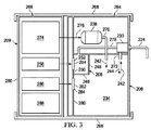
ここで主に図3を参照して、減圧サブシステム206および減圧評価サブシステム208の説明に役立つ別の非限定的な実施形態を説明する。図3は、断面で示す。この説明に役立つ実施形態では、減圧サブシステム206および減圧評価サブシステム208は組み合わされて、減圧療法ユニット209になる。減圧療法ユニット209は、第1の部分264と第2の部分266とを有してもよく、第1の部分は、廃棄できるように設計されていてもよく、かつ第1の部分264に流体を隔離し、および第2の部分は、第1の部分264とは流体的に隔離されていてもよく、かつ再使用され得るより高価な品目および構成要素を含んでもよい。第1の部分264および第2の部分266は、一体式ハウジングによって、またはブラケット268もしくは他の装置によってのいずれかで、互いに近接して保持され得る。この説明に役立つ実施形態では、減圧源238は、減圧242を導管270に供給するポンプヘッドであり、その導管は、減圧を液溜め234に供給する。減圧242は別の導管272に供給され、その導管は、減圧242をコネクタ230に供給する。コネクタ230は減圧を、複合導管224の一部とし得る減圧供給導管(明示せず)に供給する。複合導管224は組織部位に減圧を供給する。減圧療法ユニット209の第2の部分266はポンプ制御ユニット274を含み、ポンプ制御ユニットは、リンキングインターフェース276を使用してポンプのエネルギーを減圧源238のポンプヘッドに提供し得る。
Referring now primarily to FIG. 3, another non-limiting embodiment is described that helps illustrate the
評価用減圧は、複合導管224の一部とし得る減圧評価導管(明示せず)を使用して、組織部位からコネクタ230へ供給される。評価用減圧は、図1に示すものと同様の方法で、導管278によってコネクタ230から評価室246へ供給される。評価室246は、密封されたエンクロージャ248を含み、そのエンクロージャは壁250を含む。壁250は、第1のダイヤフラム254などの第1の可動部分252を含む。第1の部分264には第1の圧力検出器258が含まれ、第1の圧力検出器は、第1の可動部分252と実質的に整列されている。第1の圧力検出器258は、評価室246とは流体的に隔離されている。減圧下では、第1の可動部分252は、中立位置から変位位置へ内側に移動する。第1の圧力検出器258は、減圧の影響を受けた第1の可動部分252の変位を感知するように動作可能であり、かつ、インジケータ上に、または信号によって減圧の変化を表示する。それゆえ、第1の圧力検出器258は、組織部位における圧力レベルを評価するように動作可能である。
Evaluation vacuum is provided to the
液溜め234は、第2のダイヤフラム284などの第2の可動部分282を有する壁280を含み得る。減圧の影響を受けて、第2の可動部分282は、中立位置から変位位置へ液溜め234内へ移り得る。第1の部分264には第2の圧力検出器286が含まれ、第2の圧力検出器286は、第2の可動部分282と実質的に整列され得る。第2の圧力検出器286は、液溜め234とは流体的に隔離されている。第2の圧力検出器286は、第2の可動部分282の変位を感知しかつ液溜め234内の圧力または圧力の変化を決定するのを支援するように動作可能である。組織部位における圧力を示す第1の圧力検出器258からの減圧データ、および液溜め234における圧力を示す第2の圧力検出器286からのデータを使用して、減圧治療システムの性能を評価し得る。
The
ポンプ制御ユニット274、第1の圧力検出器258、第2の検出器286は、隔離室260内に含まれて、埃および他の小さな汚染物質を回避するのを助け得る。隔離室260は、1つ以上の通気口を含んでもよく、およびバッテリーなどの動力装置288を含んで、電気エネルギーを様々な構成要素、例えば、ポンプ制御ユニット274、第1の圧力検出器258、および第2の圧力検出器286に提供してもよい。加えて、第1の部分264は、所望の圧力などの入力を受信するユーザインターフェースを含んでもよい。第1の部分264は、組織におけるまたは液溜め234内の圧力を視覚的に表示するためにインジケータ(図示せず)を含んでもよい。減圧療法ユニット209を用いて、再使用が望まれ得る高価な構成要素が第1の部分264内に配置され、かつ第2の部分266に配置されている、汚染されたまたは汚染される可能性のある部分と流体的に隔離されることを留意されたい。
A
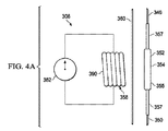
本明細書で示す、説明に役立つ非限定的な実施形態では、構成要素の多数の組み合わせを使用して、可動部分152、252、282の変位を感知し得る。ここで、変位を感知するためのいくつもの説明に役立つ非限定的な実施形態を示す。ここで主に図4Aおよび4Bを参照して、減圧評価サブシステム308の一部分を説明する。評価室346の一部分を、壁350が第1のダイヤフラム354などの第1の可動部分352を有しているものとして示す。第1のダイヤフラム354は、ターゲット355と撓み性または半撓み性の周辺部分357とを含み得る。この説明に役立つ非限定的な実施形態では、第1のダイヤフラム354の少なくとも一部分、例えば少なくともターゲット355は、フェライト材で覆われているかまたはフェライト材製である。
In the illustrative, non-limiting embodiment shown herein, multiple combinations of components may be used to sense displacement of the
第1の圧力検出器358が、第1の可動部分352に近接して配置されるが、評価室346の内部とは流体的に隔離または分離されている。第1の圧力検出器358は、隔離室360(一部を示す)内に配置される。この例では、第1の圧力検出器358は、電磁コイル390を含む。図4Bに示唆するように、フェライトを用いて第1の可動部分352を評価室346内へ変位させることによって、電磁コイル390が受けるインダクタンスを変える。インダクタンスの変化を測定し、かつそれを使用して、第1の可動部分352の変位を判断し得る。例えば、磁束が減少すると、減圧が大きくなったことが分かり、および第1の可動部分352の変位を較正して、気圧に対する評価室346内部の圧力を表示し得る。圧力変化または圧力は、インジケータ362上に表示してもよいし、または別の場所で表示することを含め、さらに処理するために信号を送信してもよい。
A
ここで主に図5Aおよび5Bを参照して、減圧評価サブシステム408の一部分の説明に役立つ別の非限定的な実施形態を説明する。評価室446の一部分を、壁450を有するとして示す。壁450は、第1のダイヤフラム454とし得る第1の可動部分452を含む。第1のダイヤフラム454は、ターゲット455と、撓み性または半撓み性の周辺部457とを含む。ターゲット455は永久磁石492を含む。
Referring now primarily to FIGS. 5A and 5B, another non-limiting embodiment is described that helps illustrate a portion of the reduced
第1の圧力検出器458が評価室446の外側に配置され、かつ評価室446からは流体的に隔離されている。第1の圧力検出器458は隔離室460(その一部を示す)内に配置されている。第1の圧力検出器458は、磁場495または磁場495の変化を感知するためのホール効果センサー494とし得る。磁場495の変化は、第1の可動部分452上の永久磁石492の動きに起因する。磁場495の変化を使用して、信号を生成するか、または評価室446内の減圧または減圧の変化をインジケータ462上に表示する。
A
ここで主に図6Aおよび6Bを参照して、減圧評価サブシステム508の一部分の説明に役立つ別の非限定的な実施形態を説明する。評価室546の一部分を示し、評価室は壁550を含む。壁550は、第1のダイヤフラム554などの第1の可動部分552を含む。第1のダイヤフラム554は、ターゲット555と、撓み性または半撓み性の周辺部557とを含む。第1の可動部分552上のターゲット555は、フェライトや、静電容量センサー596によって感知され得る他の材料を含む。
Referring now primarily to FIGS. 6A and 6B, another non-limiting embodiment is described that helps illustrate a portion of the reduced
第1の可動部分552に近接して第1の圧力検出器558が配置されてもよく、第1の圧力検出器は、評価室546とは流体的に隔離されている。第1の圧力検出器558は、隔離室560、またはハウジング内にあってもよい。この説明に役立つ実施形態では、第1の圧力検出器558は静電容量センサー596であり、そのため、第1の可動部分552が変位することによって、静電容量センサー596によって感知される静電容量の変化を引き起こす。この変化を使用して、図6Bに示すような第1の可動部分552の変位を検出する。変位は、圧力変化または評価室546内で受ける圧力の表示としてもよく、および信号を生成しても、またはインジケータ562上に表示してもよい。概して、第1の可動部分552と静電容量センサー596との間の静電容量は、それらの間の距離の二乗に比例する。
A
ここで主に図7Aおよび7Bを参照して、減圧評価サブシステム608の説明に役立つ非限定的な実施形態の一部分を説明する。減圧評価サブシステム608は、評価室646(その一部のみを示す)を含み、評価室は壁650を含む。壁650は第1の可動部分652を含む。第1の可動部分652は第1のダイヤフラム654とし得る。第1のダイヤフラム654はターゲット655を含み、そのターゲット655は、ターゲット655と壁650とを結合する撓み性または半撓み性の部分657を有し得る。撓み性または半撓み性の部分657は、ターゲット655が動けるようにする。減圧下で、第1の可動部分652は、図7Bに示すように中立位置から変位位置へ評価室646内へ内側に動く。
Referring now mainly to FIGS. 7A and 7B, a portion of a non-limiting embodiment that helps illustrate the
第1の圧力検出器658が評価室646とは流体的に分離され、かつ第1の可動部分652と実質的に整列している。第1の圧力検出器658は、隔離室660の内側にあってもよい。この実施形態では、第1の圧力検出器658は超音波センサー697であり、第1の可動部分652上の反射体691に当たる超音波を送信する。超音波センサー697は、第1の可動部分652の変位を感知し、かつ変位を示す信号を発生させる。信号を、圧力測定値をインジケータ662上に示すため、またはさらに処理するために使用し得る。
A
ここで主に図8Aおよび8Bを参照して、減圧評価サブシステム708の一部分の説明に役立つ別の非限定的な実施形態を説明する。減圧評価サブシステム708は、評価室746(一部を示す)を含む。評価室746は、第1の可動部分752を有する壁750を含む。第1の可動部分752は第1のダイヤフラム754とし得る。第1のダイヤフラム754は、ターゲット755と、撓み性または半撓み性の部分757とを含み得る。第1の可動部分752は、減圧の影響を受けて動き、かつ中立位置から変位位置へ評価室746内に移り得る。
Referring now primarily to FIGS. 8A and 8B, another non-limiting embodiment is described that helps illustrate a portion of the reduced
第1の可動部分752に近接して第1の圧力検出器758が配置され、および第1の圧力検出器は、評価室746の内側とは流体的に隔離されている。第1の圧力検出器758は隔離室760内に含まれてもよい。この説明に役立つ非限定的な実施形態では、隔離室760は窓761を含む。窓761があることによって、少なくとも赤外線信号がそこを通って伝わる。第1の圧力検出器758は赤外線センサー798を含み、赤外線センサーは、窓761を通って赤外線波を伝播させ、第1の可動部分752に衝突しかつ第1の可動部分752の相対的位置を判断するように動作可能である。第1の可動部分752は赤外線波を反射する。図8Bに示すように、第1の可動部分752は、減圧の影響を受けて評価室746内に移る。赤外線センサー798は変位を検出し、かつ信号を提供できる、または変位量または対応する圧力をインジケータ762上に表示できる。
A
本発明およびその利点のいくつかを、いくつかの説明に役立つ非限定的な実施形態に関連して説明したが、添付の特許請求の範囲によって定義された本発明の範囲から逸脱せずに、様々な変更、代用、交換、および修正をなすことができることを理解されたい。説明に役立つ非限定的な一実施形態として、図4A〜8Bに示す減圧評価サブシステムの各部分のいずれかを、同様に、第2の可動部分、例えば図3の第2の可動部分282と共に使用してもよいことに留意されたい。
While the invention and some of its advantages have been described in connection with some illustrative, non-limiting embodiments, without departing from the scope of the invention as defined by the appended claims, It should be understood that various changes, substitutions, replacements, and modifications can be made. As an illustrative and non-limiting embodiment, any of the portions of the reduced pressure evaluation subsystem shown in FIGS. 4A-8B can be similarly combined with a second movable part, eg, the second
上述の利益および利点は、一実施形態に関連し得ること、またはいくつかの実施形態に関連し得ることを理解されたい。「1つの」品目への言及は、1つ以上のそれら品目を指すことをさらに理解されたい。 It should be understood that the benefits and advantages described above may relate to one embodiment or may relate to several embodiments. It is further understood that reference to “a” item refers to one or more of those items.
本明細書で説明した方法のステップは、任意の好適な順序で、または適切な場合には同時に実施し得る。 The method steps described herein may be performed in any suitable order or simultaneously, where appropriate.
適切な場合には、上述の実施形態のいずれかの態様を、説明の任意の他の実施形態の態様と組み合わせて、類似のまたは異なる特性を有しかつ同じまたは異なる問題に対処する別の例を形成する。 Where appropriate, another example of combining any aspect of the above-described embodiments with aspects of any other described embodiment, having similar or different characteristics and addressing the same or different issues Form.
好ましい実施形態の上述の説明は例示にすぎず、当業者は様々な修正をなし得ることを理解されたい。上述の明細書、例およびデータは、本発明の例示的な実施形態の構造および使用の完全な説明を提供する。本発明の様々な実施形態を、ある程度詳細に、または1つ以上の個々の実施形態を参照して上記で説明したが、当業者は、特許請求の範囲から逸脱せずに、開示の実施形態に多数の修正をなすことができる。 It should be understood that the above description of the preferred embodiments is exemplary only, and that various modifications may be made by those skilled in the art. The above specification, examples and data provide a complete description of the structure and use of exemplary embodiments of the invention. Although various embodiments of the invention have been described above in some detail or with reference to one or more individual embodiments, those skilled in the art will recognize that the disclosed embodiments can be used without departing from the scope of the claims. Many modifications can be made.
Claims (23)
前記組織部位に近接して展開配置するための治療マニホールドと;
前記患者の表皮の一部分および前記治療マニホールドを覆って流体シールを形成するシール部材と;
減圧をもたらす減圧源と;
前記治療マニホールドおよび前記減圧源に流体結合する減圧供給導管であって、前記治療マニホールドに治療用減圧を供給する減圧供給導管と;
前記組織部位に流体結合する減圧評価導管と;
前記減圧評価導管に流体結合して、前記組織部位から評価用減圧を受け取る評価室において、壁に第1の可動部分を有する密封されたエンクロージャを含み、および前記第1の可動部分が減圧の影響を受けて動くように動作可能である、評価室と;
前記評価室の前記第1の可動部分に近接し、かつ前記評価室とは流体的に隔離されている第1の圧力検出器であって、前記第1の可動部分の変位を感知するように動作可能な第1の圧力検出器と
を含むことを特徴とするシステム。 In a system for treating a tissue site of a patient using reduced pressure,
A treatment manifold for deployment in proximity to the tissue site;
A seal member that forms a fluid seal over a portion of the patient's epidermis and the treatment manifold;
A reduced pressure source providing reduced pressure;
A reduced pressure supply conduit fluidly coupled to the treatment manifold and the reduced pressure source, wherein the reduced pressure supply conduit supplies a therapeutic reduced pressure to the treatment manifold;
A reduced pressure evaluation conduit fluidly coupled to the tissue site;
An evaluation chamber fluidly coupled to the reduced pressure evaluation conduit and receiving an evaluation reduced pressure from the tissue site includes a sealed enclosure having a first movable portion on a wall, and the first movable portion is affected by reduced pressure An evaluation room operable to move upon receiving;
A first pressure detector proximate to the first movable part of the evaluation chamber and fluidly isolated from the evaluation chamber so as to sense displacement of the first movable part. And a first pressure detector operable.
前記組織部位からの流体を収容する液溜めにおいて;
前記減圧源および前記減圧供給導管に流体結合され;
壁上に第2の可動部分を有する、液溜めと;
前記液溜めの前記第2の可動部分に近接し、かつ前記液溜めとは流体的に隔離されている第2の検出器であって、前記第2の可動部分の変位を感知するように動作可能である第2の圧力検出器と
をさらに含むことを特徴とするシステム。 The system according to claim 1 or any one of claims 2 to 7,
In a reservoir containing fluid from the tissue site;
Fluidly coupled to the vacuum source and the vacuum supply conduit;
A sump having a second movable part on the wall;
A second detector proximate to the second movable part of the reservoir and fluidly isolated from the reservoir, the sensor being operable to sense displacement of the second movable part And a second pressure detector that is possible.
前記組織部位に近接して治療マニホールドを配置するステップと;
前記患者の表皮の一部分および前記治療マニホールドを覆ってシール部材を配置して流体シールを形成するステップと;
減圧源を設けるステップと;
前記治療マニホールドおよび前記減圧源に減圧供給導管を流体結合するステップと;
評価室を設けるステップと;
前記評価室と前記組織部位に減圧評価導管を流体結合して、前記評価室に評価用減圧を供給するステップにおいて、
前記評価室が、壁に第1の可動部分を有するステップと;
前記評価室の前記第1の可動部分に近接して第1の圧力検出器を配置するステップにおいて、前記第1の圧力検出器が前記評価室とは流体的に隔離されているステップと;
前記第1の圧力検出器を使用して前記第1の可動部分の変位を感知するステップと
を含むことを特徴とする方法。 In a method of treating a patient's tissue site using reduced pressure,
Placing a treatment manifold proximate to the tissue site;
Placing a seal member over a portion of the patient's epidermis and the treatment manifold to form a fluid seal;
Providing a vacuum source;
Fluidly coupling a reduced pressure supply conduit to the treatment manifold and the reduced pressure source;
Providing an evaluation room;
In the step of fluidly coupling a reduced pressure evaluation conduit to the evaluation chamber and the tissue site and supplying a reduced pressure for evaluation to the evaluation chamber,
The evaluation chamber having a first movable part on a wall;
Disposing a first pressure detector proximate to the first movable part of the evaluation chamber, wherein the first pressure detector is fluidly isolated from the evaluation chamber;
Sensing the displacement of the first movable part using the first pressure detector.
前記組織部位からの流体を収容する液溜めを設けるステップにおいて、前記液溜めが、前記減圧源および前記減圧供給導管に流体結合され、および前記液溜めが、壁に第2の可動部分を有するステップと;
前記液溜めの前記第2の可動部分に近接して第2の検出器を配置するステップにおいて、前記第2の検出器が前記液溜めとは流体的に隔離されているステップと;
前記第2の圧力検出器を使用して前記第2の可動部分の変位を感知するステップと
をさらに含むことを特徴とする方法。 The method according to any one of claims 9 or 10 to 15,
Providing a reservoir for containing fluid from the tissue site, wherein the reservoir is fluidly coupled to the reduced pressure source and the reduced pressure supply conduit, and the reservoir has a second movable portion on a wall; When;
Disposing a second detector proximate to the second movable part of the reservoir, wherein the second detector is fluidly isolated from the reservoir;
Sensing the displacement of the second movable part using the second pressure detector.
第1の可動部分を備える、密封されたエンクロージャを有する評価室を形成するステップと;
遠位端部および近位端部を有する減圧評価導管を形成するステップであって、前記減圧評価導管は、前記遠位端部において前記組織部位に流体結合し、および前記近位端部において前記評価室に流体結合するステップと;
前記評価室の前記第1の可動部分に近接して配置され、かつ前記評価室とは流体的に隔離されている第1の圧力検出器を形成するステップであって、前記第1の圧力検出器が、前記第1の可動部分の変位を感知するように動作可能である、ステップと
を含むことを特徴とする方法。 In a method of manufacturing a system for measuring reduced pressure at a tissue site,
Forming an evaluation chamber having a sealed enclosure comprising a first movable part;
Forming a reduced pressure evaluation conduit having a distal end and a proximal end, wherein the reduced pressure evaluation conduit is fluidly coupled to the tissue site at the distal end and the proximal end. Fluidly coupling to the evaluation chamber;
Forming a first pressure detector disposed proximate to the first movable part of the evaluation chamber and fluidly isolated from the evaluation chamber, the first pressure detection; A vessel is operable to sense a displacement of the first movable part.
Applications Claiming Priority (9)
| Application Number | Priority Date | Filing Date | Title |
|---|---|---|---|
| US34582110P | 2010-05-18 | 2010-05-18 | |
| US34583010P | 2010-05-18 | 2010-05-18 | |
| US61/345,830 | 2010-05-18 | ||
| US61/345,821 | 2010-05-18 | ||
| US41473810P | 2010-11-17 | 2010-11-17 | |
| US61/414,738 | 2010-11-17 | ||
| US13/108,578 | 2011-05-16 | ||
| US13/108,578 US20110288535A1 (en) | 2010-05-18 | 2011-05-16 | Systems and methods for measuring reduced pressure employing an isolated fluid path |
| PCT/US2011/036879 WO2011146533A1 (en) | 2010-05-18 | 2011-05-17 | Systems and methods for measuring reduced pressure employing an isolated fluid path |
Publications (1)
| Publication Number | Publication Date |
|---|---|
| JP2013526942A true JP2013526942A (en) | 2013-06-27 |
Family
ID=44973078
Family Applications (2)
| Application Number | Title | Priority Date | Filing Date |
|---|---|---|---|
| JP2013511306A Withdrawn JP2013526942A (en) | 2010-05-18 | 2011-05-17 | System and method for measuring reduced pressure using an isolated fluid flow path |
| JP2013511305A Expired - Fee Related JP5939646B2 (en) | 2010-05-18 | 2011-05-17 | Depressurized canister and recycling method |
Family Applications After (1)
| Application Number | Title | Priority Date | Filing Date |
|---|---|---|---|
| JP2013511305A Expired - Fee Related JP5939646B2 (en) | 2010-05-18 | 2011-05-17 | Depressurized canister and recycling method |
Country Status (8)
| Country | Link |
|---|---|
| US (3) | US20110288535A1 (en) |
| EP (3) | EP2571558B1 (en) |
| JP (2) | JP2013526942A (en) |
| CN (2) | CN102883772B (en) |
| AU (2) | AU2011256218B2 (en) |
| CA (2) | CA2795233C (en) |
| TW (2) | TW201210644A (en) |
| WO (2) | WO2011146533A1 (en) |
Families Citing this family (53)
| Publication number | Priority date | Publication date | Assignee | Title |
|---|---|---|---|---|
| US20110196321A1 (en) * | 2009-06-10 | 2011-08-11 | Tyco Healthcare Group Lp | Fluid Collection Canister Including Canister Top with Filter Membrane and Negative Pressure Wound Therapy Systems Including Same |
| US20110288535A1 (en) * | 2010-05-18 | 2011-11-24 | Christopher Brian Locke | Systems and methods for measuring reduced pressure employing an isolated fluid path |
| JP2014500538A (en) | 2010-10-12 | 2014-01-09 | タニス,ケヴィン ジェイ. | Medical equipment |
| PL2648795T3 (en) * | 2010-12-08 | 2023-05-08 | Convatec Technologies Inc. | System for removing exudates from a wound site |
| US9058634B2 (en) | 2011-05-24 | 2015-06-16 | Kalypto Medical, Inc. | Method for providing a negative pressure wound therapy pump device |
| US9067003B2 (en) | 2011-05-26 | 2015-06-30 | Kalypto Medical, Inc. | Method for providing negative pressure to a negative pressure wound therapy bandage |
| DE102011110705A1 (en) * | 2011-06-01 | 2012-12-06 | Alexander May | Device for negative pressure wound treatment |
| CN107320791B (en) | 2012-03-12 | 2022-02-08 | 史密夫及内修公开有限公司 | Wound dressing apparatus for reduced pressure wound therapy |
| US10159770B2 (en) * | 2013-03-12 | 2018-12-25 | Kci Licensing, Inc. | Apparatus and method for identifying alternative cell chemistries for batteries |
| US9737649B2 (en) | 2013-03-14 | 2017-08-22 | Smith & Nephew, Inc. | Systems and methods for applying reduced pressure therapy |
| BR112015021924A2 (en) | 2013-03-14 | 2017-07-18 | Smith & Nephew Inc | systems and methods for applying reduced pressure therapy |
| JP6679483B2 (en) | 2013-08-13 | 2020-04-15 | スミス アンド ネフュー インコーポレイテッド | System and method for performing reduced pressure therapy |
| JP6644764B2 (en) | 2014-07-31 | 2020-02-12 | スミス アンド ネフュー インコーポレイテッド | Systems and methods for delivering decompression therapy |
| CN113367890B (en) | 2015-04-27 | 2023-02-21 | 史密夫及内修公开有限公司 | Pressure reducing device |
| CN107580509B (en) | 2015-05-18 | 2021-06-15 | 史密夫及内修公开有限公司 | Negative pressure wound therapy apparatus and method |
| WO2017019939A1 (en) | 2015-07-29 | 2017-02-02 | Innovative Therapies, Inc. | Wound therapy device pressure monitoring and control system |
| EP3334472B1 (en) | 2015-08-13 | 2023-11-22 | Smith&Nephew, Inc. | Systems and methods for applying reduced pressure therapy |
| US11315681B2 (en) | 2015-10-07 | 2022-04-26 | Smith & Nephew, Inc. | Reduced pressure therapy device operation and authorization monitoring |
| CN114053031A (en) | 2016-03-07 | 2022-02-18 | 史密夫及内修公开有限公司 | Wound therapy apparatus and method utilizing a negative pressure source integrated into a wound dressing |
| CA3022184A1 (en) | 2016-04-26 | 2017-11-02 | Smith & Nephew Plc | Wound dressings and methods of use with integrated negative pressure source having a fluid ingress inhibition component |
| EP3452129B1 (en) | 2016-05-03 | 2022-03-23 | Smith & Nephew plc | Negative pressure wound therapy device activation and control |
| EP3452131A1 (en) | 2016-05-03 | 2019-03-13 | Smith & Nephew PLC | Systems and methods for driving negative pressure sources in negative pressure therapy systems |
| CN109069710B (en) | 2016-05-03 | 2022-04-12 | 史密夫及内修公开有限公司 | Optimizing power delivery to a negative pressure source in a negative pressure therapy system |
| AU2017261814B2 (en) | 2016-05-13 | 2022-05-19 | Smith & Nephew, Inc. | Automatic wound coupling detection in negative pressure wound therapy systems |
| US11413388B2 (en) * | 2016-05-24 | 2022-08-16 | Somavac Medical Solutions, Inc. | Portable device with disposable reservoir for collection of internal fluid after surgery from a plurality of sites simultaneously |
| CA3034789A1 (en) | 2016-08-25 | 2018-03-01 | Smith & Nephew Plc | Absorbent negative pressure wound therapy dressing |
| AU2017335635B2 (en) | 2016-09-29 | 2023-01-05 | Smith & Nephew, Inc. | Construction and protection of components in negative pressure wound therapy systems |
| EP3519001A1 (en) | 2016-09-30 | 2019-08-07 | Smith & Nephew PLC | Negative pressure wound treatment apparatuses and methods with integrated electronics |
| EP3582821A1 (en) | 2017-02-15 | 2019-12-25 | Smith&nephew Pte. Limited | Negative pressure wound therapy apparatuses and methods for using the same |
| JP7361606B2 (en) | 2017-03-08 | 2023-10-16 | スミス アンド ネフュー ピーエルシー | Control of negative pressure wound therapy devices in the presence of fault conditions |
| US11471571B2 (en) | 2017-04-19 | 2022-10-18 | Smith & Nephew, Inc. | Negative pressure wound therapy canisters |
| WO2018206420A1 (en) | 2017-05-09 | 2018-11-15 | Smith & Nephew Plc | Redundant controls for negative pressure wound therapy systems |
| US11712508B2 (en) | 2017-07-10 | 2023-08-01 | Smith & Nephew, Inc. | Systems and methods for directly interacting with communications module of wound therapy apparatus |
| US20200179575A1 (en) * | 2017-07-31 | 2020-06-11 | Kci Licensing, Inc. | Liquid Collection Container For Negative-Pressure Therapy |
| CN111065424A (en) | 2017-09-13 | 2020-04-24 | 史密夫及内修公开有限公司 | Negative pressure wound therapy apparatus with integrated electronics and method |
| GB201718070D0 (en) | 2017-11-01 | 2017-12-13 | Smith & Nephew | Negative pressure wound treatment apparatuses and methods with integrated electronics |
| WO2019063467A1 (en) | 2017-09-29 | 2019-04-04 | T.J.Smith And Nephew,Limited | Negative pressure wound therapy apparatus with removable panels |
| EP3703632B1 (en) | 2017-11-01 | 2024-04-03 | Smith & Nephew plc | Negative pressure wound treatment apparatuses and methods with integrated electronics |
| GB201718072D0 (en) | 2017-11-01 | 2017-12-13 | Smith & Nephew | Negative pressure wound treatment apparatuses and methods with integrated electronics |
| GB201718054D0 (en) | 2017-11-01 | 2017-12-13 | Smith & Nephew | Sterilization of integrated negative pressure wound treatment apparatuses and sterilization methods |
| GB201813282D0 (en) | 2018-08-15 | 2018-09-26 | Smith & Nephew | System for medical device activation and opertion |
| US10624794B2 (en) | 2018-02-12 | 2020-04-21 | Healyx Labs, Inc. | Negative pressure wound therapy systems, devices, and methods |
| GB201804347D0 (en) | 2018-03-19 | 2018-05-02 | Smith & Nephew Inc | Securing control of settings of negative pressure wound therapy apparatuses and methods for using the same |
| GB201806988D0 (en) | 2018-04-30 | 2018-06-13 | Quintanar Felix Clarence | Power source charging for negative pressure wound therapy apparatus |
| USD888225S1 (en) | 2018-04-30 | 2020-06-23 | Smith & Nephew Asia Pacific Pte. Limited | Pump and canister assembly for negative pressure wound therapy |
| EP3787704A1 (en) | 2018-04-30 | 2021-03-10 | Smith & Nephew Asia Pacific Pte Limited | Systems and methods for controlling dual mode negative pressure wound therapy apparatus |
| GB201806992D0 (en) * | 2018-04-30 | 2018-06-13 | Blackburn Iain Michael | Exhaust vent for a negative pressure wound therapy system |
| GB201808438D0 (en) | 2018-05-23 | 2018-07-11 | Smith & Nephew | Systems and methods for determining blockages in a negative pressure wound therapy system |
| WO2020018328A1 (en) * | 2018-07-16 | 2020-01-23 | Kci Licensing, Inc. | Wound therapy system with conduit blockage detection |
| USD898925S1 (en) | 2018-09-13 | 2020-10-13 | Smith & Nephew Plc | Medical dressing |
| GB201820668D0 (en) | 2018-12-19 | 2019-01-30 | Smith & Nephew Inc | Systems and methods for delivering prescribed wound therapy |
| USD895787S1 (en) * | 2019-05-10 | 2020-09-08 | Kci Licensing, Inc. | Negative pressure therapy device |
| GB201914534D0 (en) * | 2019-10-08 | 2019-11-20 | Oxford Healthtech Ltd | Sensor device for a compression garment |
Family Cites Families (179)
| Publication number | Priority date | Publication date | Assignee | Title |
|---|---|---|---|---|
| US1355846A (en) | 1920-02-06 | 1920-10-19 | David A Rannells | Medical appliance |
| US2547758A (en) | 1949-01-05 | 1951-04-03 | Wilmer B Keeling | Instrument for treating the male urethra |
| US2632443A (en) | 1949-04-18 | 1953-03-24 | Eleanor P Lesher | Surgical dressing |
| GB692578A (en) | 1949-09-13 | 1953-06-10 | Minnesota Mining & Mfg | Improvements in or relating to drape sheets for surgical use |
| US2682873A (en) | 1952-07-30 | 1954-07-06 | Johnson & Johnson | General purpose protective dressing |
| NL189176B (en) | 1956-07-13 | 1900-01-01 | Hisamitsu Pharmaceutical Co | PLASTER BASED ON A SYNTHETIC RUBBER. |
| US2969057A (en) | 1957-11-04 | 1961-01-24 | Brady Co W H | Nematodic swab |
| US3066672A (en) | 1960-09-27 | 1962-12-04 | Jr William H Crosby | Method and apparatus for serial sampling of intestinal juice |
| US3367332A (en) | 1965-08-27 | 1968-02-06 | Gen Electric | Product and process for establishing a sterile area of skin |
| US3520300A (en) | 1967-03-15 | 1970-07-14 | Amp Inc | Surgical sponge and suction device |
| US3568675A (en) | 1968-08-30 | 1971-03-09 | Clyde B Harvey | Fistula and penetrating wound dressing |
| US3682180A (en) | 1970-06-08 | 1972-08-08 | Coilform Co Inc | Drain clip for surgical drain |
| US3690315A (en) * | 1970-08-26 | 1972-09-12 | Abbott Lab | Combined container and package particularly adapted for urinary drainage assemblies |
| BE789293Q (en) | 1970-12-07 | 1973-01-15 | Parke Davis & Co | MEDICO-SURGICAL DRESSING FOR BURNS AND SIMILAR LESIONS |
| US3826254A (en) | 1973-02-26 | 1974-07-30 | Verco Ind | Needle or catheter retaining appliance |
| US3948436A (en) * | 1974-11-04 | 1976-04-06 | Packaging Industries, Inc. | Multilayer bag |
| DE2527706A1 (en) | 1975-06-21 | 1976-12-30 | Hanfried Dr Med Weigand | DEVICE FOR THE INTRODUCTION OF CONTRAST AGENTS INTO AN ARTIFICIAL INTESTINAL OUTLET |
| DE2640413C3 (en) | 1976-09-08 | 1980-03-27 | Richard Wolf Gmbh, 7134 Knittlingen | Catheter monitor |
| NL7710909A (en) | 1976-10-08 | 1978-04-11 | Smith & Nephew | COMPOSITE STRAPS. |
| GB1562244A (en) | 1976-11-11 | 1980-03-05 | Lock P M | Wound dressing materials |
| US4080970A (en) | 1976-11-17 | 1978-03-28 | Miller Thomas J | Post-operative combination dressing and internal drain tube with external shield and tube connector |
| US4139004A (en) | 1977-02-17 | 1979-02-13 | Gonzalez Jr Harry | Bandage apparatus for treating burns |
| US4184510A (en) | 1977-03-15 | 1980-01-22 | Fibra-Sonics, Inc. | Valued device for controlling vacuum in surgery |
| US4165748A (en) | 1977-11-07 | 1979-08-28 | Johnson Melissa C | Catheter tube holder |
| US4245637A (en) | 1978-07-10 | 1981-01-20 | Nichols Robert L | Shutoff valve sleeve |
| SE414994B (en) | 1978-11-28 | 1980-09-01 | Landstingens Inkopscentral | VENKATETERFORBAND |
| WO1980001139A1 (en) | 1978-12-06 | 1980-06-12 | Svedman Paul | Device for treating tissues,for example skin |
| US4266545A (en) | 1979-04-06 | 1981-05-12 | Moss James P | Portable suction device for collecting fluids from a closed wound |
| US4284079A (en) | 1979-06-28 | 1981-08-18 | Adair Edwin Lloyd | Method for applying a male incontinence device |
| US4261363A (en) | 1979-11-09 | 1981-04-14 | C. R. Bard, Inc. | Retention clips for body fluid drains |
| US4569348A (en) | 1980-02-22 | 1986-02-11 | Velcro Usa Inc. | Catheter tube holder strap |
| ATE14835T1 (en) | 1980-03-11 | 1985-08-15 | Schmid Eduard | SKIN GRAFT PRESSURE BANDAGE. |
| US4297995A (en) | 1980-06-03 | 1981-11-03 | Key Pharmaceuticals, Inc. | Bandage containing attachment post |
| US4333468A (en) | 1980-08-18 | 1982-06-08 | Geist Robert W | Mesentery tube holder apparatus |
| US4465485A (en) | 1981-03-06 | 1984-08-14 | Becton, Dickinson And Company | Suction canister with unitary shut-off valve and filter features |
| US4392853A (en) | 1981-03-16 | 1983-07-12 | Rudolph Muto | Sterile assembly for protecting and fastening an indwelling device |
| US4373519A (en) | 1981-06-26 | 1983-02-15 | Minnesota Mining And Manufacturing Company | Composite wound dressing |
| US4392858A (en) | 1981-07-16 | 1983-07-12 | Sherwood Medical Company | Wound drainage device |
| US4419097A (en) | 1981-07-31 | 1983-12-06 | Rexar Industries, Inc. | Attachment for catheter tube |
| AU550575B2 (en) | 1981-08-07 | 1986-03-27 | Richard Christian Wright | Wound drainage device |
| SE429197B (en) | 1981-10-14 | 1983-08-22 | Frese Nielsen | SAR TREATMENT DEVICE |
| DE3146266A1 (en) | 1981-11-21 | 1983-06-01 | B. Braun Melsungen Ag, 3508 Melsungen | COMBINED DEVICE FOR A MEDICAL SUCTION DRAINAGE |
| US4551139A (en) | 1982-02-08 | 1985-11-05 | Marion Laboratories, Inc. | Method and apparatus for burn wound treatment |
| DE3209661A1 (en) * | 1982-03-17 | 1983-09-29 | Heinz Dieter Dipl.-Ing.(FH) 6050 Offenbach Sonnleitner | Measuring instrument for measuring physical variables, for example air pressure |
| US4475909A (en) | 1982-05-06 | 1984-10-09 | Eisenberg Melvin I | Male urinary device and method for applying the device |
| EP0100148B1 (en) | 1982-07-06 | 1986-01-08 | Dow Corning Limited | Medical-surgical dressing and a process for the production thereof |
| NZ206837A (en) | 1983-01-27 | 1986-08-08 | Johnson & Johnson Prod Inc | Thin film adhesive dressing:backing material in three sections |
| US4548202A (en) | 1983-06-20 | 1985-10-22 | Ethicon, Inc. | Mesh tissue fasteners |
| US4540412A (en) | 1983-07-14 | 1985-09-10 | The Kendall Company | Device for moist heat therapy |
| US4543100A (en) | 1983-11-01 | 1985-09-24 | Brodsky Stuart A | Catheter and drain tube retainer |
| US4602715A (en) * | 1983-11-08 | 1986-07-29 | Aero Mayflower Transit Company, Inc. | Shipping container for electronic components |
| US4525374A (en) | 1984-02-27 | 1985-06-25 | Manresa, Inc. | Treating hydrophobic filters to render them hydrophilic |
| GB2157958A (en) | 1984-05-03 | 1985-11-06 | Ernest Edward Austen Bedding | Ball game net support |
| US4897081A (en) | 1984-05-25 | 1990-01-30 | Thermedics Inc. | Percutaneous access device |
| US5215522A (en) | 1984-07-23 | 1993-06-01 | Ballard Medical Products | Single use medical aspirating device and method |
| GB8419745D0 (en) | 1984-08-02 | 1984-09-05 | Smith & Nephew Ass | Wound dressing |
| US4872450A (en) | 1984-08-17 | 1989-10-10 | Austad Eric D | Wound dressing and method of forming same |
| US4655754A (en) | 1984-11-09 | 1987-04-07 | Stryker Corporation | Vacuum wound drainage system and lipids baffle therefor |
| US4826494A (en) | 1984-11-09 | 1989-05-02 | Stryker Corporation | Vacuum wound drainage system |
| US4605399A (en) | 1984-12-04 | 1986-08-12 | Complex, Inc. | Transdermal infusion device |
| US5037397A (en) | 1985-05-03 | 1991-08-06 | Medical Distributors, Inc. | Universal clamp |
| US4640688A (en) | 1985-08-23 | 1987-02-03 | Mentor Corporation | Urine collection catheter |
| US4710165A (en) | 1985-09-16 | 1987-12-01 | Mcneil Charles B | Wearable, variable rate suction/collection device |
| US4758220A (en) | 1985-09-26 | 1988-07-19 | Alcon Laboratories, Inc. | Surgical cassette proximity sensing and latching apparatus |
| US4733659A (en) | 1986-01-17 | 1988-03-29 | Seton Company | Foam bandage |
| EP0256060A1 (en) | 1986-01-31 | 1988-02-24 | OSMOND, Roger L. W. | Suction system for wound and gastro-intestinal drainage |
| US4838883A (en) | 1986-03-07 | 1989-06-13 | Nissho Corporation | Urine-collecting device |
| JPS62281965A (en) | 1986-05-29 | 1987-12-07 | テルモ株式会社 | Catheter and catheter fixing member |
| GB8621884D0 (en) | 1986-09-11 | 1986-10-15 | Bard Ltd | Catheter applicator |
| GB2195255B (en) | 1986-09-30 | 1991-05-01 | Vacutec Uk Limited | Apparatus for vacuum treatment of an epidermal surface |
| US4743232A (en) | 1986-10-06 | 1988-05-10 | The Clinipad Corporation | Package assembly for plastic film bandage |
| DE3634569A1 (en) | 1986-10-10 | 1988-04-21 | Sachse Hans E | CONDOM CATHETER, A URINE TUBE CATHETER FOR PREVENTING RISING INFECTIONS |
| JPS63135179A (en) | 1986-11-26 | 1988-06-07 | 立花 俊郎 | Subcataneous drug administration set |
| GB8628564D0 (en) | 1986-11-28 | 1987-01-07 | Smiths Industries Plc | Anti-foaming agent suction apparatus |
| GB8706116D0 (en) | 1987-03-14 | 1987-04-15 | Smith & Nephew Ass | Adhesive dressings |
| US4787888A (en) | 1987-06-01 | 1988-11-29 | University Of Connecticut | Disposable piezoelectric polymer bandage for percutaneous delivery of drugs and method for such percutaneous delivery (a) |
| US4863449A (en) | 1987-07-06 | 1989-09-05 | Hollister Incorporated | Adhesive-lined elastic condom cathether |
| US4930997A (en) | 1987-08-19 | 1990-06-05 | Bennett Alan N | Portable medical suction device |
| US5176663A (en) | 1987-12-02 | 1993-01-05 | Pal Svedman | Dressing having pad with compressibility limiting elements |
| US4906240A (en) | 1988-02-01 | 1990-03-06 | Matrix Medica, Inc. | Adhesive-faced porous absorbent sheet and method of making same |
| US4985019A (en) | 1988-03-11 | 1991-01-15 | Michelson Gary K | X-ray marker |
| US4867372A (en) * | 1988-04-29 | 1989-09-19 | Jeffrey Patterson | Mailing/shipping container |
| GB8812803D0 (en) | 1988-05-28 | 1988-06-29 | Smiths Industries Plc | Medico-surgical containers |
| US4919654A (en) | 1988-08-03 | 1990-04-24 | Kalt Medical Corporation | IV clamp with membrane |
| US5000741A (en) | 1988-08-22 | 1991-03-19 | Kalt Medical Corporation | Transparent tracheostomy tube dressing |
| EP0379416B1 (en) | 1989-01-16 | 1995-03-08 | Roussel-Uclaf | Azabicycloheptene derivatives and their salts, process for their preparation, their use as medicaments and compositions containing them |
| GB8906100D0 (en) | 1989-03-16 | 1989-04-26 | Smith & Nephew | Laminates |
| US5261893A (en) | 1989-04-03 | 1993-11-16 | Zamierowski David S | Fastening system and method |
| US5527293A (en) | 1989-04-03 | 1996-06-18 | Kinetic Concepts, Inc. | Fastening system and method |
| US5100396A (en) | 1989-04-03 | 1992-03-31 | Zamierowski David S | Fluidic connection system and method |
| US4969880A (en) | 1989-04-03 | 1990-11-13 | Zamierowski David S | Wound dressing and treatment method |
| US5358494A (en) | 1989-07-11 | 1994-10-25 | Svedman Paul | Irrigation dressing |
| JP2719671B2 (en) | 1989-07-11 | 1998-02-25 | 日本ゼオン株式会社 | Wound dressing |
| US5232453A (en) | 1989-07-14 | 1993-08-03 | E. R. Squibb & Sons, Inc. | Catheter holder |
| GB2235877A (en) | 1989-09-18 | 1991-03-20 | Antonio Talluri | Closed wound suction apparatus |
| US5146732A (en) * | 1989-10-26 | 1992-09-15 | Resource America, Inc. | Recycle shipping assembly |
| US5134994A (en) | 1990-02-12 | 1992-08-04 | Say Sam L | Field aspirator in a soft pack with externally mounted container |
| US5092858A (en) | 1990-03-20 | 1992-03-03 | Becton, Dickinson And Company | Liquid gelling agent distributor device |
| US5213851A (en) * | 1990-04-17 | 1993-05-25 | Alfred University | Process for preparing ferrite films by radio-frequency generated aerosol plasma deposition in atmosphere |
| ATE112739T1 (en) * | 1990-05-04 | 1994-10-15 | Guenter Witz Ag | PACKAGING FOR SHOCK-SENSITIVE CONSUMABLES. |
| US5117976A (en) * | 1991-01-09 | 1992-06-02 | Sanyo Energy (U.S.A.) Corp. | Display packaging for batteries |
| US5223228A (en) | 1991-02-25 | 1993-06-29 | Baxter International Inc. | Tray for autotransfusion module |
| US5149331A (en) | 1991-05-03 | 1992-09-22 | Ariel Ferdman | Method and device for wound closure |
| US5278100A (en) | 1991-11-08 | 1994-01-11 | Micron Technology, Inc. | Chemical vapor deposition technique for depositing titanium silicide on semiconductor wafers |
| US5645081A (en) * | 1991-11-14 | 1997-07-08 | Wake Forest University | Method of treating tissue damage and apparatus for same |
| US5636643A (en) | 1991-11-14 | 1997-06-10 | Wake Forest University | Wound treatment employing reduced pressure |
| US5279550A (en) | 1991-12-19 | 1994-01-18 | Gish Biomedical, Inc. | Orthopedic autotransfusion system |
| US5178282A (en) * | 1991-12-19 | 1993-01-12 | Alcon Surgical, Inc. | Modular surgical packaging system |
| US5167613A (en) | 1992-03-23 | 1992-12-01 | The Kendall Company | Composite vented wound dressing |
| FR2690617B1 (en) | 1992-04-29 | 1994-06-24 | Cbh Textile | TRANSPARENT ADHESIVE DRESSING. |
| JP3190152B2 (en) * | 1993-01-20 | 2001-07-23 | 株式会社日立製作所 | Resource recycling and product distribution methods |
| DE4306478A1 (en) | 1993-03-02 | 1994-09-08 | Wolfgang Dr Wagner | Drainage device, in particular pleural drainage device, and drainage method |
| US5342376A (en) | 1993-05-03 | 1994-08-30 | Dermagraphics, Inc. | Inserting device for a barbed tissue connector |
| US6241747B1 (en) | 1993-05-03 | 2001-06-05 | Quill Medical, Inc. | Barbed Bodily tissue connector |
| US5344415A (en) | 1993-06-15 | 1994-09-06 | Deroyal Industries, Inc. | Sterile system for dressing vascular access site |
| US5632093A (en) * | 1993-07-19 | 1997-05-27 | Elias; Sharon A. | Inductive sensor and method for detecting displacement of a body |
| US5437651A (en) | 1993-09-01 | 1995-08-01 | Research Medical, Inc. | Medical suction apparatus |
| US5449009A (en) * | 1993-09-30 | 1995-09-12 | Sherwood Medical Company | Fluid disposal system |
| JP3476022B2 (en) * | 1993-10-15 | 2003-12-10 | 横河電機株式会社 | Electric / pneumatic converter |
| US5549584A (en) | 1994-02-14 | 1996-08-27 | The Kendall Company | Apparatus for removing fluid from a wound |
| JP3344845B2 (en) * | 1994-04-15 | 2002-11-18 | 株式会社日立製作所 | Product recycling system |
| US5607388A (en) | 1994-06-16 | 1997-03-04 | Hercules Incorporated | Multi-purpose wound dressing |
| US5556375A (en) | 1994-06-16 | 1996-09-17 | Hercules Incorporated | Wound dressing having a fenestrated base layer |
| US5664270A (en) | 1994-07-19 | 1997-09-09 | Kinetic Concepts, Inc. | Patient interface system |
| JP3687794B2 (en) | 1994-08-22 | 2005-08-24 | キネティック コンセプツ インコーポレイテッド | Wound drainage technology |
| US5645540A (en) | 1994-10-11 | 1997-07-08 | Stryker Corporation | Blood conservation system |
| DE29504378U1 (en) | 1995-03-15 | 1995-09-14 | Mtg Medizinisch Tech Geraeteba | Electronically controlled low-vacuum pump for chest and wound drainage |
| US5860555A (en) * | 1995-06-07 | 1999-01-19 | Mayled; Edward C. | Storage and shipping container |
| GB9523253D0 (en) * | 1995-11-14 | 1996-01-17 | Mediscus Prod Ltd | Portable wound treatment apparatus |
| US5742883A (en) * | 1996-07-31 | 1998-04-21 | Hewlett-Packard Company | Product integrated return mailer |
| US5753820A (en) * | 1996-10-25 | 1998-05-19 | Arthur D. Little, Inc. | Fluid pressure sensing unit incorporating diaphragm deflection sensing array |
| US5839058A (en) * | 1996-11-01 | 1998-11-17 | Ericsson Inc. | Recyclable cellular telephone and method and apparatus for supporting the use of a recyclable cellular telephone within a cellular telephone network |
| US5829229A (en) * | 1997-04-04 | 1998-11-03 | Motorola, Inc. | Recyclable packaging system and process for using the same |
| US6135116A (en) | 1997-07-28 | 2000-10-24 | Kci Licensing, Inc. | Therapeutic method for treating ulcers |
| GB9719520D0 (en) | 1997-09-12 | 1997-11-19 | Kci Medical Ltd | Surgical drape and suction heads for wound treatment |
| AU755496B2 (en) | 1997-09-12 | 2002-12-12 | Kci Licensing, Inc. | Surgical drape and suction head for wound treatment |
| SE9704185D0 (en) | 1997-11-14 | 1997-11-14 | Astra Pharma Prod | Inhalation device |
| US6071267A (en) | 1998-02-06 | 2000-06-06 | Kinetic Concepts, Inc. | Medical patient fluid management interface system and method |
| US6488643B1 (en) | 1998-10-08 | 2002-12-03 | Kci Licensing, Inc. | Wound healing foot wrap |
| GB9822341D0 (en) * | 1998-10-13 | 1998-12-09 | Kci Medical Ltd | Negative pressure therapy using wall suction |
| US6109444A (en) * | 1998-12-21 | 2000-08-29 | Lucent Technologies Inc. | Multi-function packing insert |
| US6287316B1 (en) | 1999-03-26 | 2001-09-11 | Ethicon, Inc. | Knitted surgical mesh |
| US7799004B2 (en) | 2001-03-05 | 2010-09-21 | Kci Licensing, Inc. | Negative pressure wound treatment apparatus and infection identification system and method |
| US6856821B2 (en) | 2000-05-26 | 2005-02-15 | Kci Licensing, Inc. | System for combined transcutaneous blood gas monitoring and vacuum assisted wound closure |
| US6991643B2 (en) | 2000-12-20 | 2006-01-31 | Usgi Medical Inc. | Multi-barbed device for retaining tissue in apposition and methods of use |
| TR200401397T4 (en) | 2000-02-24 | 2004-07-21 | Venetec International, Inc. | Universal catheter insertion system. |
| US7069236B1 (en) * | 2000-07-10 | 2006-06-27 | Canon Usa, Inc. | System and methods to effect return of a consumer product |
| US6540705B2 (en) | 2001-02-22 | 2003-04-01 | Core Products International, Inc. | Ankle brace providing upper and lower ankle adjustment |
| US6532346B2 (en) * | 2001-08-02 | 2003-03-11 | Hewlett-Packard Company | Systems and methods for printing shipping labels for recycling printing device replaceable components |
| US6705469B2 (en) * | 2001-10-31 | 2004-03-16 | Xerox Corporation | One-piece foldable protective shipping container/insert |
| US6648862B2 (en) * | 2001-11-20 | 2003-11-18 | Spheric Products, Ltd. | Personally portable vacuum desiccator |
| US20030196413A1 (en) * | 2002-04-17 | 2003-10-23 | Michael Schapiro | Wedding gown cleaning and preservation system |
| US20040000581A1 (en) * | 2002-06-20 | 2004-01-01 | Sealed Air Corporation (Us) | Polypropylene/cushioned envelope |
| JP2004145876A (en) * | 2002-10-04 | 2004-05-20 | Ricoh Co Ltd | Supply commodity recovery management system, method, program, and storage medium |
| US7976519B2 (en) | 2002-12-31 | 2011-07-12 | Kci Licensing, Inc. | Externally-applied patient interface system and method |
| JP2005335910A (en) * | 2004-05-28 | 2005-12-08 | Fuji Xerox Co Ltd | Logistics management system of products |
| WO2006035342A1 (en) * | 2004-09-27 | 2006-04-06 | Koninklijke Philips Electronics N.V. | Magnetic sensor for input devices |
| US7631758B2 (en) * | 2005-04-13 | 2009-12-15 | Vaporlok Technology, Llc | Shipping and storage containers |
| EP1871271B1 (en) * | 2005-04-22 | 2018-04-11 | Becton, Dickinson and Company | Prepackaged medical device and method |
| CA2923372C (en) | 2005-09-07 | 2019-07-30 | Smith & Nephew, Inc. | Self contained wound dressing apparatus |
| CA2635697A1 (en) * | 2006-02-02 | 2007-08-09 | Coloplast A/S | A suction system |
| JP2009525086A (en) * | 2006-02-02 | 2009-07-09 | コロプラスト アクティーゼルスカブ | Devices, pumps and systems for promoting wound healing |
| TW200821001A (en) * | 2006-09-19 | 2008-05-16 | Kci Licensing Inc | Reduced pressure treatment system having blockage clearing and dual-zone pressure protection capabilities |
| US7876546B2 (en) * | 2006-09-19 | 2011-01-25 | Kci Licensing Inc. | Component module for a reduced pressure treatment system |
| US7938786B2 (en) | 2006-12-13 | 2011-05-10 | Devicor Medical Products, Inc. | Vacuum timing algorithm for biopsy device |
| EP2339362A1 (en) * | 2007-02-26 | 2011-06-29 | Fujikura Ltd. | Magnetic sensor module and piston position detector |
| WO2008131362A2 (en) * | 2007-04-20 | 2008-10-30 | Doheny Eye Institute | Personal surgical center |
| GB0712736D0 (en) | 2007-07-02 | 2007-08-08 | Smith & Nephew | Apparatus |
| US20090007525A1 (en) * | 2007-07-06 | 2009-01-08 | Ecological Packaging Resources Ltd | Method for reusing returnable packaging |
| US20090035609A1 (en) * | 2007-07-31 | 2009-02-05 | Apple Inc. | Intelligent universal rechargeable batteries for battery charging system for mobile and accessory devices |
| US7819298B2 (en) | 2008-02-14 | 2010-10-26 | Ethicon Endo-Surgery, Inc. | Surgical stapling apparatus with control features operable with one hand |
| US20090240218A1 (en) | 2008-03-20 | 2009-09-24 | Tyco Healthcare Group Lp | Wound Therapy System |
| US20100001055A1 (en) * | 2008-07-07 | 2010-01-07 | Watterson Billy J | Recycling kit and method |
| AU2009268997B2 (en) | 2008-07-08 | 2015-04-02 | Smith & Nephew Inc. | Portable negative pressure wound therapy device |
| US8708984B2 (en) * | 2008-12-24 | 2014-04-29 | Kci Licensing, Inc. | Reduced-pressure wound treatment systems and methods employing manifold structures |
| US20110049004A1 (en) * | 2009-08-28 | 2011-03-03 | Summit Container Corporation | Box insert |
| DE102009039336B4 (en) * | 2009-08-29 | 2023-07-13 | Paul Hartmann Ag | Vacuum therapy device with pressure sensor |
| US20110288535A1 (en) * | 2010-05-18 | 2011-11-24 | Christopher Brian Locke | Systems and methods for measuring reduced pressure employing an isolated fluid path |
| US8409160B2 (en) * | 2010-05-18 | 2013-04-02 | Kci Licensing, Inc. | Reduced-pressure treatment systems and methods employing a fluidly isolated pump control unit |
-
2011
- 2011-05-16 US US13/108,578 patent/US20110288535A1/en not_active Abandoned
- 2011-05-16 US US13/108,719 patent/US8641693B2/en active Active
- 2011-05-17 WO PCT/US2011/036879 patent/WO2011146533A1/en active Application Filing
- 2011-05-17 EP EP11722255.4A patent/EP2571558B1/en not_active Revoked
- 2011-05-17 EP EP11721950.1A patent/EP2571557B1/en not_active Not-in-force
- 2011-05-17 JP JP2013511306A patent/JP2013526942A/en not_active Withdrawn
- 2011-05-17 AU AU2011256218A patent/AU2011256218B2/en not_active Ceased
- 2011-05-17 AU AU2011256217A patent/AU2011256217B2/en not_active Ceased
- 2011-05-17 CN CN201180022891.5A patent/CN102883772B/en not_active Expired - Fee Related
- 2011-05-17 CA CA2795233A patent/CA2795233C/en not_active Expired - Fee Related
- 2011-05-17 JP JP2013511305A patent/JP5939646B2/en not_active Expired - Fee Related
- 2011-05-17 CA CA2795232A patent/CA2795232A1/en not_active Abandoned
- 2011-05-17 EP EP16173287.0A patent/EP3085407B1/en active Active
- 2011-05-17 CN CN2011800216975A patent/CN102869406A/en active Pending
- 2011-05-17 WO PCT/US2011/036878 patent/WO2011146532A2/en active Application Filing
- 2011-05-18 TW TW100117517A patent/TW201210644A/en unknown
- 2011-05-18 TW TW100117515A patent/TW201200178A/en unknown
-
2014
- 2014-01-08 US US14/150,542 patent/US9474836B2/en not_active Expired - Fee Related
Also Published As
| Publication number | Publication date |
|---|---|
| WO2011146532A3 (en) | 2012-01-26 |
| CN102883772A (en) | 2013-01-16 |
| CA2795233A1 (en) | 2011-11-24 |
| US20110288535A1 (en) | 2011-11-24 |
| US20140121617A1 (en) | 2014-05-01 |
| WO2011146533A1 (en) | 2011-11-24 |
| TW201200178A (en) | 2012-01-01 |
| AU2011256217A1 (en) | 2012-10-25 |
| AU2011256218A1 (en) | 2012-10-18 |
| US20110288511A1 (en) | 2011-11-24 |
| EP2571558A2 (en) | 2013-03-27 |
| CN102883772B (en) | 2016-01-20 |
| JP5939646B2 (en) | 2016-06-22 |
| US9474836B2 (en) | 2016-10-25 |
| EP3085407B1 (en) | 2021-11-24 |
| CA2795232A1 (en) | 2011-11-24 |
| TW201210644A (en) | 2012-03-16 |
| AU2011256218B2 (en) | 2016-04-21 |
| CA2795233C (en) | 2017-11-07 |
| WO2011146532A2 (en) | 2011-11-24 |
| EP2571557A1 (en) | 2013-03-27 |
| US8641693B2 (en) | 2014-02-04 |
| EP2571558B1 (en) | 2016-06-29 |
| CN102869406A (en) | 2013-01-09 |
| EP3085407A1 (en) | 2016-10-26 |
| JP2013526373A (en) | 2013-06-24 |
| AU2011256217B2 (en) | 2016-06-09 |
| EP2571557B1 (en) | 2015-06-24 |
Similar Documents
| Publication | Publication Date | Title |
|---|---|---|
| JP2013526942A (en) | System and method for measuring reduced pressure using an isolated fluid flow path | |
| US11229733B2 (en) | Reduced-pressure treatment systems and methods employing a fluidly isolated pump control unit | |
| US8529526B2 (en) | Dressing reduced-pressure indicators, systems, and methods | |
| EP2595588B1 (en) | Systems and methods for electrically detecting the presence of exudate in dressings | |
| US20160346134A1 (en) | Drape having microstrain inducing projections for treating a wound site | |
| AU2011279913A1 (en) | Systems and methods for electrically detecting the presence of exudate in dressings | |
| CN113631128A (en) | Absorbent dressing with remote measurement of dressing moisture | |
| US20220305192A1 (en) | Abdominal Negative-Pressure Therapy Dressing With Closed-Loop Force Management Control | |
| WO2023094915A1 (en) | Systems, methods, and apparatuses for fluid level detection in fluid storage canisters |
Legal Events
| Date | Code | Title | Description |
|---|---|---|---|
| A300 | Application deemed to be withdrawn because no request for examination was validly filed |
Free format text: JAPANESE INTERMEDIATE CODE: A300 Effective date: 20140805 |