CN107580509B - Negative pressure wound therapy apparatus and method - Google Patents
Negative pressure wound therapy apparatus and method Download PDFInfo
- Publication number
- CN107580509B CN107580509B CN201680028863.7A CN201680028863A CN107580509B CN 107580509 B CN107580509 B CN 107580509B CN 201680028863 A CN201680028863 A CN 201680028863A CN 107580509 B CN107580509 B CN 107580509B
- Authority
- CN
- China
- Prior art keywords
- pump
- pump assembly
- pump chamber
- chamber
- outlet
- Prior art date
- Legal status (The legal status is an assumption and is not a legal conclusion. Google has not performed a legal analysis and makes no representation as to the accuracy of the status listed.)
- Active
Links
- 238000009581 negative-pressure wound therapy Methods 0.000 title claims description 11
- 238000000034 method Methods 0.000 title abstract description 15
- 230000005291 magnetic effect Effects 0.000 claims abstract description 72
- 239000012530 fluid Substances 0.000 claims abstract description 55
- 206010052428 Wound Diseases 0.000 claims description 89
- 208000027418 Wounds and injury Diseases 0.000 claims description 89
- 239000012528 membrane Substances 0.000 claims description 44
- 230000000712 assembly Effects 0.000 claims description 42
- 238000000429 assembly Methods 0.000 claims description 42
- 239000000463 material Substances 0.000 claims description 27
- 238000004891 communication Methods 0.000 claims description 15
- 230000002441 reversible effect Effects 0.000 claims description 12
- 239000006260 foam Substances 0.000 claims description 9
- 239000007788 liquid Substances 0.000 claims description 9
- 210000000416 exudates and transudate Anatomy 0.000 claims description 8
- 239000000853 adhesive Substances 0.000 claims description 7
- 230000001070 adhesive effect Effects 0.000 claims description 7
- 239000004973 liquid crystal related substance Substances 0.000 claims description 3
- 239000013078 crystal Substances 0.000 claims description 2
- 238000003466 welding Methods 0.000 claims description 2
- 229910052451 lead zirconate titanate Inorganic materials 0.000 description 41
- 238000002560 therapeutic procedure Methods 0.000 description 13
- 230000008901 benefit Effects 0.000 description 10
- 230000035876 healing Effects 0.000 description 6
- 210000001519 tissue Anatomy 0.000 description 6
- 230000002745 absorbent Effects 0.000 description 5
- 239000002250 absorbent Substances 0.000 description 5
- 238000003491 array Methods 0.000 description 5
- 230000006870 function Effects 0.000 description 4
- 230000002209 hydrophobic effect Effects 0.000 description 4
- 239000007787 solid Substances 0.000 description 4
- 230000009471 action Effects 0.000 description 3
- 238000004873 anchoring Methods 0.000 description 3
- 230000008569 process Effects 0.000 description 3
- 238000005086 pumping Methods 0.000 description 3
- 230000000699 topical effect Effects 0.000 description 3
- 208000034656 Contusions Diseases 0.000 description 2
- 206010030113 Oedema Diseases 0.000 description 2
- 238000013459 approach Methods 0.000 description 2
- 230000001580 bacterial effect Effects 0.000 description 2
- 230000009286 beneficial effect Effects 0.000 description 2
- 230000017531 blood circulation Effects 0.000 description 2
- 230000009519 contusion Effects 0.000 description 2
- 208000014674 injury Diseases 0.000 description 2
- 239000000696 magnetic material Substances 0.000 description 2
- 229910001172 neodymium magnet Inorganic materials 0.000 description 2
- 229920000139 polyethylene terephthalate Polymers 0.000 description 2
- 239000005020 polyethylene terephthalate Substances 0.000 description 2
- 230000001737 promoting effect Effects 0.000 description 2
- 238000000926 separation method Methods 0.000 description 2
- 230000035939 shock Effects 0.000 description 2
- RYGMFSIKBFXOCR-UHFFFAOYSA-N Copper Chemical compound [Cu] RYGMFSIKBFXOCR-UHFFFAOYSA-N 0.000 description 1
- 206010056340 Diabetic ulcer Diseases 0.000 description 1
- 206010063560 Excessive granulation tissue Diseases 0.000 description 1
- 229910001209 Low-carbon steel Inorganic materials 0.000 description 1
- 241001465754 Metazoa Species 0.000 description 1
- 229910052779 Neodymium Inorganic materials 0.000 description 1
- 208000004210 Pressure Ulcer Diseases 0.000 description 1
- 229910000831 Steel Inorganic materials 0.000 description 1
- 208000002847 Surgical Wound Diseases 0.000 description 1
- 208000000558 Varicose Ulcer Diseases 0.000 description 1
- 206010048038 Wound infection Diseases 0.000 description 1
- QJVKUMXDEUEQLH-UHFFFAOYSA-N [B].[Fe].[Nd] Chemical compound [B].[Fe].[Nd] QJVKUMXDEUEQLH-UHFFFAOYSA-N 0.000 description 1
- 230000003187 abdominal effect Effects 0.000 description 1
- 238000005299 abrasion Methods 0.000 description 1
- 230000001154 acute effect Effects 0.000 description 1
- 230000015572 biosynthetic process Effects 0.000 description 1
- 238000007664 blowing Methods 0.000 description 1
- 230000000747 cardiac effect Effects 0.000 description 1
- 230000008859 change Effects 0.000 description 1
- 230000001684 chronic effect Effects 0.000 description 1
- 239000004020 conductor Substances 0.000 description 1
- 230000006378 damage Effects 0.000 description 1
- 230000007423 decrease Effects 0.000 description 1
- 230000007547 defect Effects 0.000 description 1
- 230000000694 effects Effects 0.000 description 1
- 229920001971 elastomer Polymers 0.000 description 1
- 239000000806 elastomer Substances 0.000 description 1
- 239000013536 elastomeric material Substances 0.000 description 1
- 230000005284 excitation Effects 0.000 description 1
- 239000003302 ferromagnetic material Substances 0.000 description 1
- 239000000945 filler Substances 0.000 description 1
- 239000007789 gas Substances 0.000 description 1
- 210000001126 granulation tissue Anatomy 0.000 description 1
- 230000006872 improvement Effects 0.000 description 1
- 208000015181 infectious disease Diseases 0.000 description 1
- 238000003780 insertion Methods 0.000 description 1
- 230000037431 insertion Effects 0.000 description 1
- HFGPZNIAWCZYJU-UHFFFAOYSA-N lead zirconate titanate Chemical compound [O-2].[O-2].[O-2].[O-2].[O-2].[Ti+4].[Zr+4].[Pb+2] HFGPZNIAWCZYJU-UHFFFAOYSA-N 0.000 description 1
- 230000007246 mechanism Effects 0.000 description 1
- 229910052751 metal Inorganic materials 0.000 description 1
- 239000002184 metal Substances 0.000 description 1
- 238000012986 modification Methods 0.000 description 1
- 230000004048 modification Effects 0.000 description 1
- QEFYFXOXNSNQGX-UHFFFAOYSA-N neodymium atom Chemical compound [Nd] QEFYFXOXNSNQGX-UHFFFAOYSA-N 0.000 description 1
- -1 polyethylene terephthalate Polymers 0.000 description 1
- 229920001296 polysiloxane Polymers 0.000 description 1
- 229920002635 polyurethane Polymers 0.000 description 1
- 239000004814 polyurethane Substances 0.000 description 1
- 230000004044 response Effects 0.000 description 1
- 238000007789 sealing Methods 0.000 description 1
- 239000010959 steel Substances 0.000 description 1
- 230000004936 stimulating effect Effects 0.000 description 1
- 238000006467 substitution reaction Methods 0.000 description 1
- 230000009772 tissue formation Effects 0.000 description 1
- 230000008733 trauma Effects 0.000 description 1
- 230000000472 traumatic effect Effects 0.000 description 1
- 238000011144 upstream manufacturing Methods 0.000 description 1
- 238000013022 venting Methods 0.000 description 1
- 230000035899 viability Effects 0.000 description 1
- 238000004804 winding Methods 0.000 description 1
Images


Classifications
-
- A—HUMAN NECESSITIES
- A61—MEDICAL OR VETERINARY SCIENCE; HYGIENE
- A61M—DEVICES FOR INTRODUCING MEDIA INTO, OR ONTO, THE BODY; DEVICES FOR TRANSDUCING BODY MEDIA OR FOR TAKING MEDIA FROM THE BODY; DEVICES FOR PRODUCING OR ENDING SLEEP OR STUPOR
- A61M1/00—Suction or pumping devices for medical purposes; Devices for carrying-off, for treatment of, or for carrying-over, body-liquids; Drainage systems
- A61M1/90—Negative pressure wound therapy devices, i.e. devices for applying suction to a wound to promote healing, e.g. including a vacuum dressing
- A61M1/96—Suction control thereof
- A61M1/962—Suction control thereof having pumping means on the suction site, e.g. miniature pump on dressing or dressing capable of exerting suction
-
- A61F13/05—
-
- A—HUMAN NECESSITIES
- A61—MEDICAL OR VETERINARY SCIENCE; HYGIENE
- A61M—DEVICES FOR INTRODUCING MEDIA INTO, OR ONTO, THE BODY; DEVICES FOR TRANSDUCING BODY MEDIA OR FOR TAKING MEDIA FROM THE BODY; DEVICES FOR PRODUCING OR ENDING SLEEP OR STUPOR
- A61M1/00—Suction or pumping devices for medical purposes; Devices for carrying-off, for treatment of, or for carrying-over, body-liquids; Drainage systems
- A61M1/64—Containers with integrated suction means
- A61M1/68—Containers incorporating a flexible member creating suction
- A61M1/684—Containers incorporating a flexible member creating suction bellows-type
-
- A—HUMAN NECESSITIES
- A61—MEDICAL OR VETERINARY SCIENCE; HYGIENE
- A61M—DEVICES FOR INTRODUCING MEDIA INTO, OR ONTO, THE BODY; DEVICES FOR TRANSDUCING BODY MEDIA OR FOR TAKING MEDIA FROM THE BODY; DEVICES FOR PRODUCING OR ENDING SLEEP OR STUPOR
- A61M1/00—Suction or pumping devices for medical purposes; Devices for carrying-off, for treatment of, or for carrying-over, body-liquids; Drainage systems
- A61M1/80—Suction pumps
-
- A—HUMAN NECESSITIES
- A61—MEDICAL OR VETERINARY SCIENCE; HYGIENE
- A61M—DEVICES FOR INTRODUCING MEDIA INTO, OR ONTO, THE BODY; DEVICES FOR TRANSDUCING BODY MEDIA OR FOR TAKING MEDIA FROM THE BODY; DEVICES FOR PRODUCING OR ENDING SLEEP OR STUPOR
- A61M2205/00—General characteristics of the apparatus
- A61M2205/02—General characteristics of the apparatus characterised by a particular materials
- A61M2205/0272—Electro-active or magneto-active materials
-
- A—HUMAN NECESSITIES
- A61—MEDICAL OR VETERINARY SCIENCE; HYGIENE
- A61M—DEVICES FOR INTRODUCING MEDIA INTO, OR ONTO, THE BODY; DEVICES FOR TRANSDUCING BODY MEDIA OR FOR TAKING MEDIA FROM THE BODY; DEVICES FOR PRODUCING OR ENDING SLEEP OR STUPOR
- A61M2205/00—General characteristics of the apparatus
- A61M2205/10—General characteristics of the apparatus with powered movement mechanisms
- A61M2205/106—General characteristics of the apparatus with powered movement mechanisms reciprocating
-
- A—HUMAN NECESSITIES
- A61—MEDICAL OR VETERINARY SCIENCE; HYGIENE
- A61M—DEVICES FOR INTRODUCING MEDIA INTO, OR ONTO, THE BODY; DEVICES FOR TRANSDUCING BODY MEDIA OR FOR TAKING MEDIA FROM THE BODY; DEVICES FOR PRODUCING OR ENDING SLEEP OR STUPOR
- A61M2205/00—General characteristics of the apparatus
- A61M2205/36—General characteristics of the apparatus related to heating or cooling
- A61M2205/3606—General characteristics of the apparatus related to heating or cooling cooled
-
- A—HUMAN NECESSITIES
- A61—MEDICAL OR VETERINARY SCIENCE; HYGIENE
- A61M—DEVICES FOR INTRODUCING MEDIA INTO, OR ONTO, THE BODY; DEVICES FOR TRANSDUCING BODY MEDIA OR FOR TAKING MEDIA FROM THE BODY; DEVICES FOR PRODUCING OR ENDING SLEEP OR STUPOR
- A61M2205/00—General characteristics of the apparatus
- A61M2205/36—General characteristics of the apparatus related to heating or cooling
- A61M2205/3613—General characteristics of the apparatus related to heating or cooling by body heat
-
- A—HUMAN NECESSITIES
- A61—MEDICAL OR VETERINARY SCIENCE; HYGIENE
- A61M—DEVICES FOR INTRODUCING MEDIA INTO, OR ONTO, THE BODY; DEVICES FOR TRANSDUCING BODY MEDIA OR FOR TAKING MEDIA FROM THE BODY; DEVICES FOR PRODUCING OR ENDING SLEEP OR STUPOR
- A61M2205/00—General characteristics of the apparatus
- A61M2205/36—General characteristics of the apparatus related to heating or cooling
- A61M2205/366—General characteristics of the apparatus related to heating or cooling by liquid heat exchangers
-
- A—HUMAN NECESSITIES
- A61—MEDICAL OR VETERINARY SCIENCE; HYGIENE
- A61M—DEVICES FOR INTRODUCING MEDIA INTO, OR ONTO, THE BODY; DEVICES FOR TRANSDUCING BODY MEDIA OR FOR TAKING MEDIA FROM THE BODY; DEVICES FOR PRODUCING OR ENDING SLEEP OR STUPOR
- A61M2205/00—General characteristics of the apparatus
- A61M2205/36—General characteristics of the apparatus related to heating or cooling
- A61M2205/3693—General characteristics of the apparatus related to heating or cooling by mechanical waves, e.g. ultrasonic
Abstract
An apparatus and method for treating a wound of a patient with negative pressure is provided. The device comprises a pump chamber having at least one movable side of the chamber. The movable side moves between the intake stroke and the exhaust stroke upon application of the electrical potential. Fluid is drawn into the pump chamber during the intake stroke and expelled from the pump chamber during the exhaust stroke. The pump system may have magnetic or piezoelectric elements that drive the movement of the sides of the pump chamber.
Description
Background
Technical Field
Embodiments or arrangements disclosed herein relate to methods and apparatus for dressing and treating wounds with Topical Negative Pressure (TNP) therapy. For example, but not limiting of, any of the embodiments disclosed herein relate to treating a wound with reduced pressure provided by a pump kit. Although not required, any embodiment of the pump kit can be sterile. As another non-limiting example, any of the embodiments disclosed herein relate to an apparatus and method for controlling the operation of a TNP system.
Background
Many different types of wound dressings are known for aiding the healing process in humans or animals. These different types of wound dressings include many different types of materials and layers, for example, pads such as gauze pads and/or foam pads. Topical negative pressure ("TNP") therapy, sometimes referred to as vacuum assisted closure, negative pressure wound therapy or reduced pressure wound therapy, is widely recognized as a beneficial mechanism for improving the healing rate of wounds. Such treatment is applicable to a wide range of wounds, such as incision wounds, open wounds, abdominal wounds, and the like.
TNP therapy helps close and heal wounds by reducing tissue edema, promoting blood flow, stimulating the formation of granulation tissue, removing excess exudate, and may reduce bacterial loads and, therefore, the likelihood of wound infection. Furthermore, TNP therapy allows for less external disturbance of the wound and promotes faster healing.
Disclosure of Invention
Embodiments of the present disclosure relate to devices and methods for wound therapy. Some wound treatment devices described herein include a pump system for providing negative pressure to a wound site. The wound therapy apparatus may also include a wound dressing that may be used in conjunction with the pump system described herein, and a connector for connecting the wound dressing to the pump system.
According to one embodiment, a pump assembly is provided. The pump assembly includes a first diaphragm and a second diaphragm that together define a chamber therebetween. The pump assembly further includes a first magnetic actuator proximate an inner surface of the first diaphragm and a second magnetic actuator proximate an inner surface of the second diaphragm. One or both of the first and second magnetic actuators may provide a magnetic field that applies a magnetic force to the first and second magnetic actuators and the first and second diaphragms, causing the diaphragms to move toward and away from each other to pump fluid through the chamber.
Optionally, one or more of the first magnetic actuator and the second magnetic actuator is an electromagnet configured to generate a magnetic field upon passage of a current therethrough.
Optionally, one or more of the first and second magnetic actuators is a permanent magnet providing a permanent magnetic field.
According to another embodiment, an apparatus for use in negative pressure wound therapy is provided. The apparatus includes a pump system. The pump system includes a pump assembly including a pump chamber having an interior surface, an exterior surface, a first side, a second side generally opposite the first side, an inlet, and an outlet. The pump assembly further comprises: a first magnetic actuator coupled to a first side of the pump chamber; and a second magnetic actuator coupled to a second side of the pump chamber. One or both of the first and second magnetic actuators is an electromagnet actuatable to generate a magnetic field that exerts a force on one of the first and second magnetic actuators to move the pump chamber between the extended and collapsed positions to pump fluid through the chamber.
According to another embodiment, there is provided a combination of a wound dressing and the apparatus described in the preceding paragraph, wherein the pump system is configured to pump fluid from the wound dressing during negative pressure wound therapy.
According to another embodiment, a wound dressing for use in negative pressure wound therapy is provided. The wound dressing includes a dressing body including one or more layers and configured to be removably disposed over a wound site. The wound dressing further includes one or more pump assemblies disposed on and fluidly connected to at least one of the one or more layers and configured to pump fluid from the wound site. Each of the one or more pump assemblies includes a pump chamber defined by an interior surface of a first side and a second side generally opposite the first side, an inlet, and an outlet. Each pump assembly further comprises: a first magnetic actuator coupled to an interior surface of a first side of the pump chamber; and a second magnetic actuator coupled to an interior surface of the second side of the pump chamber. One or both of the first and second magnetic actuators is an electromagnet actuatable to generate a magnetic field that exerts a force on one of the first and second magnetic actuators to move the pump chamber between the extended and collapsed positions to pump fluid through the chamber.
Drawings
Embodiments of the present disclosure will now be described, by way of example only, with reference to the accompanying drawings, in which:
FIG. 1 is a schematic cross-sectional view of an embodiment of a pump assembly.
FIG. 2 is a schematic cross-sectional view of an embodiment of a pump assembly.
FIG. 3 is a schematic cross-sectional view of an embodiment of a pump assembly.
FIG. 4 is a schematic cross-sectional view of an embodiment of a pump assembly.
FIG. 5 is a schematic cross-sectional view of an embodiment of a pump assembly.
FIG. 6 is a schematic cross-sectional view of an embodiment of a pump assembly.
Fig. 7A-7B show schematic top views of an array of pump assemblies.
Fig. 8 shows a schematic top view of an array comprising pump assemblies.
Fig. 9 shows a schematic top view of a pump system including a pump assembly.
Fig. 10 shows a schematic top view of a pump system in fluid communication with a wound dressing.
Fig. 11A shows a schematic top view of a wound dressing with a pump system.
Fig. 11B shows a schematic top view of a wound dressing with a pump system.
Fig. 12A-12C show schematic cross-sectional side views of a pump assembly.
Fig. 12D shows a schematic perspective view of a diaphragm of the pump system.
Fig. 13 shows a schematic perspective view of a pump assembly.
Fig. 14A-14B show schematic cross-sectional side views of a pump assembly.
Fig. 15A shows a schematic cross-sectional side view of a pump assembly.
Fig. 15B shows a schematic perspective view of a pump assembly.
FIG. 15C shows a perspective view of a diaphragm of the pump assembly.
Fig. 16A-16B show schematic perspective views of a pump assembly.
Fig. 17A-17B show schematic cross-sectional side views of a pump assembly.
Fig. 18A-18B show schematic cross-sectional side views of a diaphragm of a pump assembly.
Fig. 19A-19B show schematic cross-sectional side views of a diaphragm of a pump assembly.
Detailed Description
Embodiments disclosed herein relate to devices and methods for treating wounds using reduced pressure, including pumps and wound dressing components and devices. Devices and components, if present, including wound covering and filler materials are sometimes collectively referred to herein as dressings.
It will be appreciated that reference is made to wounds throughout this specification. It should be understood that the term wound should be interpreted broadly and encompasses open and closed wounds in which the skin is torn, cut or punctured or where trauma causes contusion or any other epidermal injury or other condition or defect on the skin of a patient or which otherwise benefits from reduced pressure treatment. Thus, a wound is broadly defined as any damaged area of tissue that may or may not produce fluid. Examples of such wounds include, but are not limited to, acute wounds, chronic wounds, surgical and other incisions, subacute and dehiscent wounds, traumatic wounds, flaps and skin grafts, tears, abrasions, contusions, burns, diabetic ulcers, pressure ulcers, stomas, surgical wounds, venous ulcers, and the like. In some embodiments disclosed herein, the components of the TNP system described herein may be particularly suitable for incision wounds that exude small amounts of wound exudate.
It will be understood that embodiments of the present disclosure are generally applicable for use in a topical negative pressure ("TNP") therapy system. In short, negative pressure wound therapy facilitates the closure and healing of many forms of "hard to heal" wounds by reducing tissue edema, promoting blood flow and granular tissue formation, and/or removing excess exudate, and may reduce bacterial loads (and thus, reduce the risk of infection). In addition, such treatment allows less interference with the wound, resulting in more rapid healing. TNP therapy systems may also assist in the healing of surgically closed wounds by removing fluid and by helping to stabilize tissue in an approximated (deployed) position. Another beneficial use of TNP therapy can be found in grafts and flaps where removal of excess fluid is important and where close proximity of the graft to the tissue is required in order to ensure tissue viability.
As used herein, reduced or negative pressure levels such as-X mmHg refer to pressure levels below standard atmospheric pressure, which corresponds to 760 mmHg (or 1 atm, 29.93 inHg, 101.325 kPa, 14.696 psi, etc.). Therefore, the negative pressure value of-X mmHg reflects an absolute pressure lower than 760 mmHg X mmHg, or in other words, reflects an absolute pressure of (760-X) mmHg. Additionally, a negative pressure that is "less than" or "less than" X mmHg corresponds to a pressure that is closer to atmospheric pressure (e.g., -40 mmHg less than-60 mmHg). A negative pressure "greater than" or "greater than" -X mmHg corresponds to a pressure further away from atmospheric pressure (e.g., -80 mmHg greater than-60 mmHg).
The operating sub-pressure range of some embodiments of the present disclosure may be between about-10 mmHg and-200 mmHg nominal operating pressure, between-20 mmHg and-150 mmHg nominal operating pressure, between about-45 mmHg and about-100 mmHg nominal operating pressure (e.g., between-45 mm Hg and-100 mm Hg, including-45 mm Hg and-100 mm Hg) (with about +/-12% hysteresis during operation), any sub-range within these ranges, or any other range as desired. In one embodiment, the nominal operating negative pressure may be-80 mm Hg, and may operate between-70 mm Hg and-90 mm Hg.
In some embodiments, the pump system may be included as part of a wound therapy device, which may include, for example, a wound dressing. In some embodiments, the pump system may be separate from the wound dressing as a stand-alone unit. This may beneficially allow the pump system to be positioned at different locations remote from the wound dressing. In some embodiments, the pump system may be attached to (e.g., incorporated in) the wound dressing to form a single unit. This can potentially reduce the form factor of the wound therapy device and reduce the length of the conduit attaching the pump system to the wound dressing.
In some embodiments, the pump system may be configured to operate in a canister-less system in which the wound dressing retains exudate drawn from the wound. Such dressings may include a filter, such as a hydrophobic filter, that prevents liquids downstream of the dressing from passing through (towards the pump system). In other embodiments, the pump system may be configured to operate in a system having a canister for storing at least a portion of exudate drawn from a wound. Such a canister may include a filter, such as a hydrophobic filter, that prevents liquid downstream of the dressing from passing (towards the pump system). In other embodiments, both the dressing and the canister may include a filter that prevents passage of liquids downstream of the dressing and canister.
Embodiments of the pump system described herein can have compact, small dimensions. In some embodiments, the pump may have a diameter of between about 5mm to 400 mm, between 10mm to 200mm, between 20mm to 100mm, between about 8 mm and about 20mm, any subrange within these ranges, or any other range desired. The pump system may have a thickness of between about 1mm to 30 mm, between 2mm to 20mm, between 3 mm to 10mm, any subrange within these ranges, or other ranges as desired. In one embodiment, the thickness may be less than about 4 mm. In some embodiments, the grid of pumps may cover an area of up to about 100mm x 100 mm.
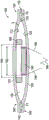
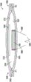
FIG. 1 illustrates a cross-sectional view of one embodiment of a pump assembly 100. The pump assembly 100 has a first diaphragm 110 and a second diaphragm 120 defining a chamber 130 therebetween. The first and second diaphragms 110, 120 may be made of a flexible material, such as a closed cell foam or an open cell foam with an impermeable outer layer. However, the first and second septums 110, 120 may be made of other suitable materials, such as polyurethane, polyethylene terephthalate (PET), and silicone. Optionally, the first and second diaphragms 110, 120 may be sealed together along their respective edges to define the chamber 130. For example, the edges of the first and second membranes 110, 120 may be sealed via welding (e.g., ultrasonic, heat, etc.) or via an adhesive. The chamber 130 may have a diameter of about 20mm3And about 1000 mm3The volume V in between.
The pump assembly 100 has an inlet portion 140 having an inlet passage 142 in fluid communication with the chamber 130. The pump assembly 100 has an outlet portion 150 with an outlet passage 152 in fluid communication with the chamber 130. Optionally, the inlet portion 140 includes a one-way valve 160 that allows fluid to flow into the chamber 130 through the inlet passage 142 but inhibits (e.g., prevents) fluid from flowing from the chamber 130 into the inlet passage 142 (e.g., inhibits reverse flow into the inlet passage 142). Optionally, the outlet portion 150 includes a one-way valve 170 that allows fluid to flow from the chamber 130 and through the outlet passage 152 but inhibits (e.g., prevents) fluid flow from the outlet passage 152 into the chamber 130 (e.g., inhibits reverse flow into the chamber 130).
With continued reference to fig. 1, the pump assembly 100 includes a first magnetic actuator (such as a magnet 180) near the inner surface 112 of the first diaphragm 110, and includes a second magnetic actuator (such as an electromagnet 190) near the inner surface 122 of the second diaphragm 120. Alternatively, the electromagnet 190 may be a voice coil. In one embodiment, the magnet 180 is attached to the inner surface 112 and the electromagnet 190 is attached to the inner surface 122. In the illustrated embodiment, the electromagnet 190 is cylindrical and has a diameter 192, and the magnet 180 is annular and has an opening with an inner diameter 184 that is greater than the diameter 192 of the electromagnet 190, allowing the electromagnet 190 to extend at least partially into the opening when the diaphragms 110, 120 are moved toward each other, as discussed further below.
In some embodiments, the electromagnet 190 may be in the form of a coil having a body formed from a length of wound wire, such as, but not limited to, a copper wire or any other electrically conductive material. Upon application of a current through the body of the electromagnet 190, a magnetic field may be generated that is directed generally in a direction parallel to the axial centerline of the coil. As will be appreciated, the direction of the magnetic field may be reversed by reversing the direction of the current through the coil. To provide current to the coil, an electrical conduit 198 may be connected across the coil. In some embodiments, the electrical conduit 198 may be a Flexible Printed Circuit (FPC) attached to a circuit board (not shown). Other types of electrical conduits, such as elongated wires, may be used.
In some embodiments, the coil may be formed by winding about 160 turns of wire or from about 100 turns or less to 200 turns or more of wire, which may, but need not be, 42 gauge (about 0.102mm diameter) wire. The wire used may be a self-bonding wire that bonds to adjacent segments of the wire upon application of heat. The wire may also be a non-self bonding wire. In some embodiments, the coil may be formed using about 200 turns of wire or up to about 260 turns of wire. Increasing the number of turns of the wire can potentially reduce ohmic losses and increase the overall efficiency of the pump assembly 100 by between about 22% and about 24%. As the number of turns of the wire is increased, thereby improving the efficiency of the pump, the size or thickness of the magnet may be reduced, thereby reducing the magnetic field external to the pump assembly 100, which may potentially interfere with the function of pacemakers and other Implantable Cardiac Devices (ICDs).
In operation, the electromagnet 190 is selectively supplied with current (e.g., alternating current) from the power supply 196. An electric current may flow through the electromagnet 190 to generate a magnetic field such that a magnetic force may be applied to the electromagnet 190 via the permanent magnetic field provided by the magnet 180. The magnetic force applied to the electromagnet 190 by the magnet 180 is transferred to the first diaphragm 110 and the second diaphragm 120, which causes the diaphragms 110, 120 to move toward and away from each other. For example, when current flows through the electromagnet 190 in one direction, the diaphragms 110, 120 may move toward each other, and when current flows through the electromagnet 190 in a second direction, opposite the first direction, to reverse the direction of the magnetic field generated in the electromagnet 190, the diaphragms 110, 120 may move away from each other.
Due to the force generated by the electromagnet 190 relative to the magnet 180, the pump assembly 100 can pump fluid (e.g., air) through the chamber 130 via reciprocating the diaphragms 110, 120 toward and away from each other. When the diaphragms 110, 120 are moved away from each other, fluid is drawn into the chamber 130 through the inlet passage 142 in the direction F1. Notably, when the diaphragms 110, 120 move apart, fluid flow from the outlet passage 152 into the chamber 130 is inhibited by the one-way valve 170 in the outlet portion 150. When the diaphragms 110, 120 move toward each other, fluid exits the chamber 130 through the outlet passage 152 in the direction F2. Notably, when the diaphragms 110, 120 move toward each other, fluid flow from the chamber 130 into the inlet passage 142 is inhibited by the one-way valve 160. Thus, the one- way valves 160, 170 ensure that fluid flows through the chamber 130 in one direction (e.g., directions F1 and F2) to thereby pump fluid from an upstream location (e.g., a wound site).
In one embodiment, the check valves 160, 170 are separate components disposed in the inlet passage 142 and the outlet passage 152, respectively. In another embodiment, the one- way valves 160, 170 are integrally formed with the diaphragms 110, 120. For example, each of the one- way valves 160, 170 may be formed by directionally piercing the walls of the diaphragms 110, 120 (e.g., where the diaphragms 110, 120 join the inlet portion 140 and the outlet portion 150). Alternatively, such directional piercing may define a flap (flap) that may move in one direction to allow flow through a flow channel (e.g., inlet channel 142 or outlet channel 152) and may move in the opposite direction to substantially seal the flow channel, depending on the direction of fluid flow.
In another embodiment, one or both of the one- way valves 160, 170 may include a material (such as liquid crystal) that changes shape when exposed to an electrical potential (e.g., a temporary potential, a continuous potential), allowing the valves 160, 170 to be fully opened or closed in addition to a one-way flow operation.
In another embodiment, one or both of the one- way valves 160, 170 may incorporate a material that expands upon contact with a liquid. Such a material may advantageously allow sealing of the flow channel and stopping of the pumping action of the pump assembly 100, for example, if a wound dressing in fluid communication with the pump assembly 100 becomes full.
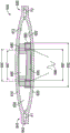
Fig. 2 shows another embodiment of a pump assembly 200. The pump assembly 200 is similar to the pump assembly 100 shown in fig. 1, except as noted below. Accordingly, the reference numbers used to designate the various components of the pump assembly 200 are the same as those used to identify the corresponding components of the pump assembly 100 in fig. 1, except that the reference number of the pump assembly 200 begins with a "2". Accordingly, descriptions with respect to the various components of the pump assembly 100 shown in fig. 1 should be understood to apply to the corresponding components of the pump assembly 200 in fig. 2, except as described below.
The pump assembly 200 has a magnet 280 near the inner surface 212 of the first diaphragm 210 and an electromagnet 290 (such as a voice coil) near the inner surface 222 of the second diaphragm 220. Optionally, magnet 280 is cylindrical, having an outer diameter 284. Optionally, the electromagnet 290 is cylindrical and has an inner diameter 292. The inner diameter 292 of the electromagnet 290 is larger than the outer diameter 284 of the magnet 280, allowing the magnet 280 to extend at least partially into the space defined by the inner diameter 292 of the electromagnet 290.
Fig. 3 illustrates another embodiment of a pump assembly 300. The pump assembly 300 is similar to the pump assembly 100 shown in fig. 1, except as noted below. Accordingly, the reference numbers used to designate the various components of the pump assembly 300 are the same as those used to identify the corresponding components of the pump assembly 100 in fig. 1, except that the reference numbers of the pump assembly 300 begin with a "3". Accordingly, descriptions with respect to the various components of the pump assembly 100 shown in fig. 1 should be understood to apply to the corresponding components of the pump assembly 300 in fig. 3, except as described below.
The pump assembly 300 has a first electromagnet 380 near the inner surface 312 of the first diaphragm 310 and a second electromagnet 390 near the inner surface 322 of the second diaphragm 320. Optionally, the first electromagnet 380 is cylindrical with an inner diameter 384. Optionally, the second electromagnet 390 is cylindrical and has an outer diameter 392. The outer diameter 392 of the second electromagnet 390 is smaller than the inner diameter 384 of the first electromagnet 380, allowing the second electromagnet 390 to extend at least partially into the space defined by the inner diameter 384 of the first electromagnet 380.
In operation, the first and second electromagnets 380 and 390 are selectively supplied with current (e.g., alternating current) from the power supply 396. For example, the first electromagnet 380 may be supplied with a current that is in anti-phase with the current supplied to the second electromagnet 390. An electric current may flow through the electromagnets 380, 390 to generate a magnetic field such that a magnetic force may be applied to the electromagnets 380, 390. The magnetic force applied to the electromagnets 380, 390 by the generated magnetic field is transferred to the first and second diaphragms 310, 320, which causes the diaphragms 310, 320 to move toward and away from each other. For example, when current flows through the electromagnets 380, 390 in one direction, the diaphragms 310, 320 may move toward each other, and when current flows through the electromagnets 380, 390 in a second direction, opposite the first direction, to reverse the direction of the magnetic field generated in the electromagnets 380, 390, the diaphragms 310, 320 may move away from each other.
Fig. 4 illustrates another embodiment of a pump assembly 400. The pump assembly 400 is similar to the pump assembly 300 shown in fig. 3, except as noted below. Accordingly, the reference numbers used to designate the various components of the pump assembly 400 are the same as those used to identify the corresponding components of the pump assembly 300 in fig. 3, except that the reference numbers of the pump assembly 400 begin with a "4". Accordingly, descriptions with respect to the various components of the pump assembly 300 shown in fig. 3 should be understood to apply to the corresponding components of the pump assembly 400 in fig. 4, except as described below.
The pump assembly 400 has a first electromagnet 480 near the inner surface 412 of the first diaphragm 410 and a second electromagnet 490 near the inner surface 422 of the second diaphragm 420. In the illustrated embodiment, the first electromagnet 480 is connected in series with the second electromagnet 490. The first electromagnet 480 is wound in the opposite direction to the second electromagnet 490.
In operation, the first and second electromagnets 480, 490 are selectively supplied with current (e.g., alternating current) from a power supply 496. An electric current may flow through the electromagnets 480, 490 to generate a magnetic field such that a magnetic force may be applied to the electromagnets 480, 490. The magnetic force applied to the electromagnets 480, 490 by the generated magnetic field is transferred to the first and second diaphragms 410, 420, which causes the diaphragms 410, 420 to move toward and away from each other. For example, when current flows through the electromagnets 480, 490 in one direction, the diaphragms 410, 420 may move toward each other, and when current flows through the electromagnets 480, 490 in a second direction, opposite the first direction, to reverse the direction of the magnetic field generated in the electromagnets 480, 490, the diaphragms 410, 420 may move away from each other.
In another embodiment (not shown), the first electromagnet 480 and the second electromagnet 490 may instead be connected in parallel, in which case the first electromagnet 480 is wound in the opposite direction as the second electromagnet 490.
Fig. 5 illustrates another embodiment of a pump assembly 500. The pump assembly 500 is similar to the pump assembly 100 shown in fig. 1, except as noted below. Accordingly, the reference numbers used to designate the various components of the pump assembly 500 are the same as those used to identify the corresponding components of the pump assembly 100 in fig. 1, except that the reference numbers of the pump assembly 500 begin with a "5". Accordingly, descriptions with respect to the various components of the pump assembly 100 shown in fig. 1 should be understood to apply to the corresponding components of the pump assembly 500 in fig. 5, except as described below.
The pump assembly 500 has a magnet 580 near the inner surface 512 of the first diaphragm 510 and an electromagnet 590 near the inner surface 522 of the second diaphragm 520. In the illustrated embodiment, the magnet 580 is shaped like a plate having a substantially flat (e.g., flat or flat) surface 582 facing the electromagnet 590.
Fig. 6 illustrates another embodiment of a pump assembly 600. The pump assembly 500 is similar to the pump assembly 100 shown in fig. 1, except as noted below. Accordingly, the reference numbers used to designate the various components of the pump assembly 600 are the same as those used to identify the corresponding components of the pump assembly 100 in fig. 1, except that the reference numbers of the pump assembly 600 begin with a "6". Accordingly, descriptions with respect to the various components of the pump assembly 100 shown in fig. 1 should be understood to apply to the corresponding components of the pump assembly 600 in fig. 6, except as described below.
The pump assembly 600 has a first magnet 680 near the inner surface 612 of the first diaphragm 610 and a first electromagnet 690 near the inner surface 622 of the second diaphragm 620. The pump assembly 600 also has a second magnet 685 near the inner surface 612 of the first diaphragm 610 and a second electromagnet 695 near the inner surface 622 of the second diaphragm 620. The first and second magnets 680, 685 are cylindrical, and the inner diameter 684 of the first magnet 680 is greater than the outer diameter 687 of the second magnet 685 such that the first magnet 680 is disposed around the second magnet 685. The first and second electromagnets 690, 695 are cylindrical in shape, and the inner diameter 692 of the first electromagnet 690 is larger than the outer diameter 697 of the second electromagnet 695 such that the first electromagnet 690 is disposed around the second electromagnet 695. In the illustrated embodiment, the inner diameter 692 of the first electromagnet 690 is larger than the outer diameter of the first magnet 680 and the inner diameter of the second electromagnet 695 is larger than the outer diameter 687 of the second magnet 685, such that the first magnet 680 and the second magnet 685 extend at least partially within the spaces in the first electromagnet 690 and the second electromagnet 695 during operation of the pump assembly 600. In an alternative embodiment, the first magnet 680 may have an inner diameter that is larger than an outer diameter of the first electromagnet 690, and the second magnet 685 may have an inner diameter that is larger than an outer diameter of the second electromagnet 695.
In operation, one or both of the first and second electromagnets 690, 695 are selectively supplied with current (e.g., alternating current) from the power supply 696. An electric current may flow through the electromagnets 690, 695 to generate a magnetic field such that a magnetic force may be applied to the electromagnets 690, 695 by the permanent magnetic field provided by the first and second magnets 680, 685. The magnetic force is transferred to the first and second diaphragms 610, 620, which causes the diaphragms 610, 620 to move toward and away from each other. For example, the diaphragms 610, 620 may move toward each other when current flows through the electromagnets 690, 695 in one direction, and the diaphragms 610, 620 may move away from each other when current flows through the electromagnets 690, 695 in a second direction opposite the first direction to reverse the direction of the magnetic field generated in the electromagnets 690, 695.
In some embodiments, one or more of the magnets disclosed herein (such as magnets 180, 280, 580, 680, 685) may be printed, electrostatically deposited, or otherwise applied onto a surface of a diaphragm (e.g., diaphragm 110, 210). In another embodiment, one or more of the magnets disclosed herein (such as magnets 180, 280, 580, 680, 685) may be attached to a corresponding surface of the septum (e.g., as an adhesive patch).
In some embodiments, one or more of the electromagnets disclosed herein (such as electromagnets 190, 290, 380, 390, 480, 490, 690, 695) may be printed, electrostatically deposited, or otherwise applied onto a surface of a diaphragm (e.g., diaphragms 110, 120, 210, 220, 310, 320, 410, 420). In another embodiment, one or more of the electromagnets disclosed herein (such as electromagnets 190, 290, 380, 390, 480, 490, 690, 695) may be attached to a corresponding surface of the septum (e.g., as an adhesive patch).
In some embodiments, one or both of the diaphragms (such as diaphragms 110, 120, 210, 220, etc.) in each pump assembly may include a bi-stable element therein to assist the diaphragms in reaching the retracted or extended positions by allowing the diaphragms to snap into the retracted and/or extended positions.
In other embodiments, a pump assembly, such as the pump assembly discussed above, may have a monostable chamber, such as the chamber 130, such that the chamber is biased in one direction (e.g., toward moving the diaphragm to an extended position), and in this case a potential is applied to the electromagnet in only one direction (e.g., to move the diaphragm to a retracted position).
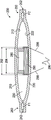
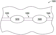
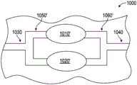
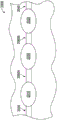
Fig. 7A-7B illustrate an array 1000 of pump assemblies, such as any of the pump assemblies disclosed above. Although fig. 7A-7B illustrate an array 1000 having two pump assemblies, one skilled in the art will recognize that the array 1000 may have more than two pump assemblies.
Fig. 7A shows a first pump assembly 1010 and a second pump assembly 1020 arranged in series between an inlet portion 1030 and an outlet portion 1040, the pump assemblies 1010, 1020 being interconnected by an intermediate portion 1050. Arranging the pump assemblies 1010, 1020 in series advantageously allows the array 1000 to have pressurization capabilities. In one embodiment, the first pump assembly 1010 and the second pump assembly 1020 can operate in anti-phase with one another to enhance fluid movement between the assemblies.
Fig. 7B shows the first pump assembly 1010 'and the second pump assembly 1020' arranged in parallel between the inlet portion 1030 and the outlet portion 1040. The inlet portion 1030 is in fluid communication with the pump assemblies 1010', 1020' via an inlet manifold 1050', and the outlet portion 1040 is in fluid communication with the pump assemblies 1010', 1020 'via an outlet manifold 1060'. Arranging the pump assemblies 1010', 1020' in parallel advantageously allows the array 1000 to produce an increased flow rate therethrough. In one embodiment, the first pump assembly 1010 'and the second pump assembly 1020' can be operated in phase relative to each other to effect movement of fluid through the array 1000.
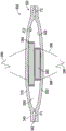
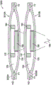
Fig. 8 illustrates another embodiment of an array 2000 comprising two or more pump assemblies (such as any of the pump assemblies disclosed above).
In the illustrated embodiment, the array 2000 has a first pump assembly 2010 and a second pump assembly 2020 disposed between an inlet section 2030 and an outlet section 2040 of the array 2000. The chamber 2050 is interposed between the pump assemblies 2010, 2020 and is interconnected with the pump assemblies 2010, 2020 via passages 2060A, 2060B. The chamber 2050 does not have magnets or electromagnets therein and may act as a pressure accumulator or a vacuum accumulator and/or to smooth flow through the array 2000. Although fig. 8 illustrates the array 2000 having two pump assemblies and one accumulator chamber, one skilled in the art will recognize that the array 2000 may have more than two pump assemblies and multiple accumulator chambers.
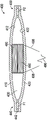
Fig. 9 illustrates another embodiment of a pump system 3000 that includes two or more pump assemblies (such as any of the pump assemblies disclosed above). The pump system 3000 has a first pump assembly 3010A and a second pump assembly 3010B arranged in separate layers, one above the other. The first and second pump assemblies 310A, 310B extend between inlet and outlet portions 3030A, 3040A, 3030B, 3040B, respectively. The first and second pump assemblies 3010A, 3010B operate in anti-phase such that a common wall or diaphragm between the assemblies 3010A, 3010B is driven by electromagnetic elements in both assemblies 3010A, 3010B.
Fig. 10 shows a pump system 4000 in fluid communication with a wound dressing 950 via a conduit 954 that connects to a port 952 on the dressing 950. The pump system 4000 may include one or more pump assemblies (such as the pump assemblies disclosed above). In some embodiments, the pump system 4000 comprises an array (such as one of the arrays disclosed above). In some embodiments, pump system 4000 may be configured to operate in a canister-less system in which a wound dressing (such as wound dressing 950) holds exudate drawn from a wound. Such dressings may include a filter, such as a hydrophobic filter, that prevents liquids downstream of the dressing from passing through (towards the pump system). In other embodiments, the pump system may be configured to operate in a system having a canister for storing at least a portion of exudate drawn from a wound. Such a canister may include a filter, such as a hydrophobic filter, that prevents liquid downstream of the dressing from passing (towards the pump system). In other embodiments, both the dressing and the canister may include a filter that prevents passage of liquids downstream of the dressing and canister. Dressing 950 may include one or more woven, non-woven foam or super absorbent layers, or combinations thereof.
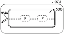
Fig. 11A illustrates one embodiment of a dressing 950A having a pump system 5000 in fluid communication with the dressing 950A via a conduit 954A. The pump system 5000 can be coupled to the dressing 950A (e.g., via an adhesive) such that the pump system 5000 is disposed on the dressing 950A. The pump system 5000 can include one or more pump assemblies P (such as the pump assemblies disclosed above). In some embodiments, the pump system 5000 includes an array (such as one of the arrays disclosed above). Dressing 950A may include one or more woven, non-woven foam, or super absorbent layers, or combinations thereof.
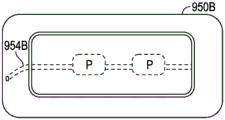
Fig. 11B illustrates another embodiment of a dressing assembly 950B having a pump system 6000 incorporated into the dressing assembly 950B. The inner conduit 954B may fluidly interconnect the pump system 6000 with the wound site (e.g., via one or more layers of the dressing 950B). The pump system 6000 may include one or more pump assemblies P (such as the pump assemblies disclosed above). In some embodiments, the pump system 6000 includes an array (such as one of the arrays disclosed above). Dressing 950B may include one or more woven, non-woven foam or super absorbent layers, or combinations thereof.
The magnets disclosed herein, such as magnets (e.g., magnets 180, 280, etc.), may be made of any suitable material, such as mild steel, sintered soft magnetic metal such as GKN 72-IBP2 (S-FeP-130), or sintered steel (or any suitable magnetic or ferromagnetic material). The magnets may be made of neodymium iron boron (NdFeB) -N45M, neodymium N33, or any other suitable material magnetic material. The material may be used to maximize field strength and minimize losses, thereby increasing the efficiency of the pump unit (e.g., pump assembly 100).
The pump assembly designs disclosed herein provide various advantages whether provided as a single unit or as part of an array, such as the array described above. For example, such a pump assembly is flexible and therefore does not create pressure points in the case of lay-flat (for example, if the pump assembly is attached to or incorporated into a wound dressing assembly). In addition, the pump assembly disclosed herein is smaller and simpler to assemble than prior rotary pumps. Furthermore, when provided as part of a wound dressing (e.g., whether attached to or integrally formed with the wound dressing), the pump assembly can be scaled with the dressing size, thereby allowing the size of the array to be adjusted along with the size of the wound dressing and thereby lower unit costs than existing pump assemblies. Another advantage of the pump assembly disclosed herein is: their configuration may allow for smaller gaps between the magnetic actuators (e.g., smaller gaps between the magnets 180 and the electromagnets 190 in fig. 1), thereby increasing the efficiency of the pump assembly.
Fig. 12A-12C illustrate cross-sectional views of embodiments of a pump assembly in which valving (valving) and/or pumping action of the pump assembly is achieved using one or more materials that change shape when exposed to an electrical potential. Examples of suitable materials include, but are not limited to, liquid crystals and piezoelectric crystals (e.g., lead zirconate titanate (PZT)). For clarity, the material that changes shape when exposed to an electrical potential will be referred to hereinafter as PZT; however, as mentioned, other suitable materials may be used instead of, or in addition to, PZT.
The pump assembly 1200 is similar to the pump assembly 100 shown in fig. 1, except as noted below. Accordingly, the reference numbers used to designate the various components of the pump assembly 1200 are the same as those used to identify the corresponding components of the pump assembly 100 in fig. 1, except that the reference numbers of the pump assembly 1200 begin with "12". Accordingly, descriptions of the various components for the pump assembly 100 shown in fig. 1 should be understood to apply to the corresponding components of the pump assembly 1200 in fig. 12A-12C, except as described below.
In the illustrated embodiment, the pump assembly 1200 has a first membrane 1210 that is movable relative to an anchoring surface 1221. Fig. 12A shows the first membrane 1210 in a default position. Fig. 12B shows the first membrane 1210 in a position deflected away from the anchor surface 1221. Fig. 12C shows the first membrane 1210 deflected toward the anchor surface 1221. The first membrane 1210 and the anchor surface 1221 can define a chamber 1230 therebetween. Chamber 1230 is surrounded by sidewalls 1219. Optionally, the sidewall 1219 and the anchor surface 1221 are rigid such that the volume in the chamber 1230 is changed solely due to movement of the first membrane 1210, rather than due to movement of the anchor surface 1221 or sidewall 1219.
The pump assembly 1200 can have an inlet passage 1242 that provides a path for fluid (e.g., air) to enter the chamber 1230. The pump assembly 1200 can have an outlet channel 1252 that provides a path for fluid to exit the chamber 1230. In the illustrated embodiment, the outlet channel 1252 is interposed between the central portion 1213 and the lateral portion 1215 of the first membrane 1210. The central portion 1213 and/or the lateral portion 1215 of the first membrane 1210 can include PZT. As discussed below, the pump assembly 1200 may be adapted in a number of ways to achieve the desired movement of the first membrane 1210. For example, PZT can be mounted on the inner surface 1212 of the first membrane 1210 and arranged such that when the PZT expands in a radial direction, the first membrane 1210 moves away from the anchor surface 1221. Additionally or alternatively, the PZT may be mounted on an outer surface 1217 of the first membrane 1210 and arranged such that when the PZT expands in a radial direction, the first membrane 1210 moves towards the anchor surface 1221. If PZT is used on both the inner surface 1212 and the outer surface 1217 of the first membrane 1210, the PZT on the inner surface 1212 can be excited out of phase with the PZT on the outer surface 1217.
Fig. 12B shows pump assembly 1200 in an intake position that lets air into chamber 1230. As shown in fig. 12B, as the first membrane 1210 moves away from the anchor surface 1221, the central portion 1213 and the lateral portion 1215 of the first membrane 1210 approach one another, thereby narrowing the outlet passage 1252 and reducing the airflow through the outlet passage 1252. Movement of the first membrane 1210 away from the anchoring surface 1221 causes the chamber 1230 to expand, drawing air into the chamber 1230 through the inlet passage 1242. Fig. 12C shows the pump assembly 1200 in a vent position that lets air out of the chamber 1230. As shown in fig. 12C, when the first membrane 1210 moves toward the anchor surface 1221, the central portion 1213 and the lateral portion 1215 of the first membrane 1210 move away from each other, thereby allowing air to more easily pass through the outlet channel 1252. As discussed in more detail below, the inlet and outlet passages 1242, 1252 may be tapered or otherwise adapted such that air passes through the passages 1242, 1252 more easily in a first direction than in an opposite direction. In this manner, the inlet passage 1242 and the outlet passage 1252 may be adapted such that air preferentially flows through the outlet passage 1252 rather than the inlet passage 1242 when the first membrane 1210 is proximate to the anchor surface 1221.
Fig. 12D is a perspective view of an embodiment of a first membrane 1210 of the pump assembly 1200. The plurality of connectors 1214 couple the central portion 1213 of the first membrane 1210 to the lateral portion 1215 of the first membrane 1210. In some embodiments, the connector 1214 includes an elastomeric material. In certain variations, the central portion 1213 is PZT, the lateral portion 1215 is PZT, and the connector 1214 is an elastomer. In some embodiments, the central portion 1213 does not include PZT and is a rigid solid that does not substantially deform as the first membrane 1210 moves between the intake and exhaust positions. For the sake of clarity, a material that does not include PZT and that does not substantially deform when the pump assembly is moved from the intake position to the exhaust position will be referred to hereinafter as a "solid". In some embodiments, the central portion 1213 is solid, the connectors 1214 are elastomeric, and the lateral portions 1215 are PZT. In certain variations, the central portion 1213 is PZT, the connectors 1214 are elastomeric, and the lateral portions 1215 are solid. In some embodiments, the central portion 1213 is bistable. Bistable refers to the central portion buckling between the intake and exhaust positions while being unstable in an intervening position between the intake and exhaust positions. In some variations, the central portion 1213 is bistable, the connector 1214 is elastomeric, and the lateral portion 1215 is PZT. In certain variations, the central portion 1213, the connectors 1214, and the lateral portion 1215 are each PZT.
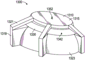
FIG. 13 illustrates a perspective view of an embodiment of a pump assembly. Pump assembly 1300 is similar to pump assembly 100 shown in fig. 1, except as noted below. Accordingly, the reference numbers used to designate the various components of the pump assembly 1300 are the same as the reference numbers used to identify the corresponding components of the pump assembly 100 in fig. 1, except that the reference numbers of the pump assembly 1300 begin with "13". Accordingly, descriptions with respect to the various components of the pump assembly 100 shown in fig. 1 should be understood to apply to the corresponding components of the pump assembly 1300 in fig. 13, except as described below.
The first diaphragm 1310 has an outlet channel 1352 surrounded by a lateral portion 1315 of the first diaphragm 1310. Outlet channel 1352 is open and closed as lateral portion 1315 extends radially outward and inward. Pump assembly 1300 has a sidewall 1319 that encloses a chamber 1330. The lateral portion 1315 has an arm 1321 connecting the first diaphragm 1310 to the sidewall 1319. In the illustrated embodiment, the pump assembly 1300 is shown in an intake position in which the first diaphragm 1310 is domed, with a surface of the first diaphragm 1310 facing the chamber 1330 having a concave shape. Air flows into the chamber 1330 through the inlet passage 1342 between the arms 1321 of the first diaphragm 1310. The entry portion 1323 of the sidewall 1319 may have a swept path geometry that facilitates air flow along the entry portion 1323 and into the chamber 1330. In the illustrated embodiment, the pump assembly 1300 is in the intake position, and the outlet channel 1352 has been narrowed such that substantially no air flows through the outlet channel 1352. As discussed below, valving of the pump assembly may be achieved by energizing the lateral portion 1315 and the PZT of the arm 1321 at slightly different times. For example, the lateral portion 1315 may be energized to close the outlet channel 1352 before the arm 1321, and then the first diaphragm 1310 may be deflected such that air is drawn into the chamber 1330 through the inlet channel 1342 rather than through the outlet channel 1352.
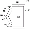
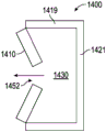
Fig. 14A-14B illustrate cross-sectional views of another embodiment of a pump assembly. The pump assembly 1400 is similar to the pump assembly 100 shown in fig. 1, except as noted below. Accordingly, the reference numbers used to designate the various components of the pump assembly 1400 are the same as those used to identify the corresponding components of the pump assembly 100 in fig. 1, except that the reference numbers of the pump assembly 1400 begin with "14". Accordingly, descriptions of the various components for the pump assembly 100 shown in fig. 1 should be understood to apply to the corresponding components of the pump assembly 1400 in fig. 14A-14B, except as described below.
FIG. 14A shows pump assembly 1400 in an intake position, wherein air enters chamber 1430 through inlet passage 1442. Fig. 14B shows the pump assembly 1400 in the exhaust position, where air exits the chamber 1430 through the outlet passage 1452. Although not shown, the pump assembly 1400 will include inlet and outlet manifold systems that direct the flow of air through the inlet passage 1442, then through the chamber 1430, and finally through the outlet passage 1452. In other words, the manifold system (not shown) would be adapted to prevent air from passing between the inlet passage 1442 and the outlet passage 1452 without passing through the chamber 1430.
In the intake position of the embodiment shown in fig. 14A, the lateral portion 1415 of the first diaphragm 1410 moves radially inward from the sidewall 1419 to open the inlet passage 1442. At the same time, the central portion 1413 of the first membrane 1410 moves radially inward away from the anchoring surface 1421, thereby closing the outlet channel 1452 and expanding the volume of the chamber 1430. In the exhaust position (FIG. 14B), the lateral portion 1415 moves radially outward toward the sidewall 1419 to close the inlet passage 1442. At the same time, the central portion 1413 of the first membrane 1410 moves radially outward toward the anchor surface 1421 of the chamber 1430, thereby opening the outlet channel 1452 and reducing the volume of the chamber 1430.
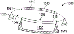
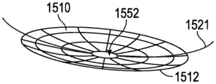
Fig. 15A-15C illustrate cross-sectional views of another embodiment of a pump assembly. The pump assembly 1500 is similar to the pump assembly 100 shown in fig. 1, except as noted below. Accordingly, the reference numbers used to designate the various components of the pump assembly 1500 are the same as those used to identify the corresponding components of the pump assembly 100 in fig. 1, except that the reference numbers of the pump assembly 1500 begin with a "15". Accordingly, descriptions of the various components for the pump assembly 100 shown in fig. 1 should be understood to apply to the corresponding components of the pump assembly 1500 in fig. 15A-15C, except as described below.
Fig. 15A shows the superposition of the first diaphragm 1510 in the intake position and the exhaust position. The first diaphragm 1510 has a white shade in the intake position and a black shade in the exhaust position. Lateral portion 1515 has arms 1521 that connect first diaphragm 1510 to ring support 1525. The arm 1521 may comprise PZT material. In some embodiments, the arm 1521 does not include PZT material. In certain embodiments, the arm 1521 and/or the first diaphragm 1510 may be bistable, i.e., flex between convex or concave positions and unstable in a flat orientation. In the intake position, inlet passage 1542 is open to allow air to enter chamber 1530. In the exhaust position, the arm 1521 seals the inlet passage 1542 while the central portion 1513 of the first diaphragm opens the outlet passage 1552, thereby allowing air within the chamber 1530 to pass to an outlet manifold (not shown) of the pump assembly 1500.
FIG. 15B is a perspective view of an embodiment of the pump assembly 1500 in an intake position. In the illustrated embodiment, inlet passage 1542 opens to connect to chamber 1530 through a gap formed when first diaphragm 1510 is moved longitudinally away from sidewall 1519. At the same time, outlet channel 1552 is sealed by the central portion 1513 of the first diaphragm 1510 expanding radially inward. Fig. 15C is a perspective view of the first diaphragm 1510 in a venting position, showing the outlet channel 1552 open when the inner surface 1512 of the first diaphragm 1510 becomes convex.
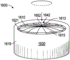
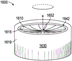
Fig. 16-16B show perspective views of another embodiment of a pump assembly. The pump assembly 1600 is similar to the pump assembly 100 shown in fig. 1, except as noted below. Accordingly, the reference numbers used to designate the various components of the pump assembly 1600 are the same as those used to identify the corresponding components of the pump assembly 100 in fig. 1, except that the reference numbers of the pump assembly 1600 begin with "16". Accordingly, descriptions of the various components for the pump assembly 100 shown in fig. 1 should be understood to apply to the corresponding components of the pump assembly 1600 in fig. 16A-16B, except as described below.
Fig. 16A is a perspective view of an embodiment of a pump assembly 1600 in an intake position. In the illustrated embodiment, the central portion 1613 of the first diaphragm 1610 moves radially inward to seal the outlet passage 1652. The central portion 1613 is also moved longitudinally away from the ring support 1619, thereby imparting a convex shape to the top surface of the first diaphragm 1610. At the same time, the lateral portion 1615 of the first diaphragm 1610 moves radially inward, thereby opening the inlet channels 1642 to allow air to enter the chamber 1630 through the annular gap formed between the ring support 1619 and the lateral portion 1615 of the first diaphragm 1610. In some embodiments, the inlet channel 1642 may occupy approximately 5% of the area of the annular gap between the lateral portion 1615 and the ring mount 1619, with the arms 1621 occupying the remainder of the annular gap. However, in other embodiments, the inlet channel 1642 may occupy more than 5% or less of the area of the annular gap between the lateral portion 1615 and the ring mount 1619.
Fig. 16B is a perspective view of an embodiment of the pump assembly 1600 in the exhaust position. The first diaphragm 1610 is bent into the chamber, giving the top surface of the first diaphragm 1610 a concave shape. The central portion 1613 of the first diaphragm moves radially outward, thereby enlarging the outlet passage 1652 and allowing air to flow from the chamber 1630 through the outlet passage 1652.
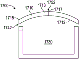
Fig. 17A-17B illustrate features of the inlet passageway 1742 and the outlet passageway 1752 of the pump assembly. The pump assembly 1700 is similar to the pump assembly 100 shown in fig. 1, except as noted below. Accordingly, the reference numbers used to designate the various components of the pump assembly 1700 are the same as those used to identify the corresponding components of the pump assembly 100 in fig. 1, except that the reference numbers of the pump assembly 1700 begin with a "17". Accordingly, descriptions of the various components for the pump assembly 100 shown in fig. 1 should be understood to apply to the corresponding components of the pump assembly 1700 in fig. 17A-17B, except as described below.
Fig. 17A shows a pump assembly 1700 in an air intake configuration. The PZT material of the first diaphragm 1710 may be excited at a frequency of about 16kHz, causing the first diaphragm 1710 to oscillate at the same frequency between an intake position and an exhaust position. In some embodiments, the PZT material of the first diaphragm is actuated at about: 16kHz, 20kHz, 40kHz, 80kHz and frequencies therebetween. The primary frequency for exciting the PZT will be in the range of about 18kHz to about 24 kHz. A diaphragm of smaller PZT will generally extend higher because the natural frequency is a function of size and aspect ratio. Smaller dimensions and greater thickness will increase the frequency. In certain embodiments, the PZT valve operates at a lower frequency than the PZT diaphragm. The excitation frequency may be selected to avoid audible frequencies. The highest normal hearing frequency for young adults is about 24kHz, which decreases to about 18kHz by middle age. Thus, higher frequencies are inaudible and therefore clearly silent. The rapid movement of first diaphragm 1710 may cause air to flow through inlet passageway 1742 and outlet passageway 1752 to have a higher reynolds number (Re). In some embodiments, the narrowing of outlet channel 1752 and the rapid movement of first septum 1710 causes an airflow through outlet channel 1752 such that Re > 1,000. In some embodiments, the Re of peak air flow through outlet channel 1752 is approximately: 500, a step of; 1,000; 2,000; 4,000; and values therebetween. Alternatively, the flow may optionally be moderately sinusoidal and may therefore have a reynolds number that varies over time. The lowest peak in reynolds number would be expected to be about 150 with the highest peak being about 6000. In some embodiments, PZT valving allows for a lower peak velocity for the same overall flow rate, thereby reducing backpressure.
Referring to fig. 17A, the pump assembly 1700 may be adapted such that it appears to be effectively closed even though the central portions 1713 do not actually contact each other's outlet passages 1752. It may be advantageous to avoid the outlet passages 1752 from being completely closed to avoid the central portions 1713 from contacting each other and generating a shock wave. Shock waves compromise pump efficiency and can cause wear on pump components. The "closing rate" may be defined as the ratio between the cross-sectional area of the outlet passage 1752 at the intake location and the cross-sectional area of the outlet passage 1752 at the exhaust location. In some embodiments, the closure rate is about: 0.8, 0.5, 0.3, 0.1, 0.03 and values in between. In certain variations, optionally, a maximum closure rate of about 0.5 may be used. In some geometries, a closure rate of 0.8 provides a measurable improvement in restricting air flow through the outlet passages 1752 in the intake position. In some embodiments, the cross-sectional area of the outlet passages 1752 in the intake position approaches a fully closed configuration such that an effective minimum closure rate is not provided. In many embodiments, a closure rate of 0.03 may optionally be selected as the minimum acceptable closure rate, as such a ratio avoids contact between PZT elements, while producing an overall size of the outlet channel 1752 in the intake position that would then be extremely small. In addition, the use of chamfered edges can improve the function of the outlet channels 1752 because sharp edges can reduce the effective width of the mini-channels to 0.65 of the actual width, while chamfering or rounding keeps it close to 1.0 — thus, the chamfered edges can allow easier flow in one direction than the other.
Referring to fig. 17B, the first diaphragm 1710 may be adapted such that the outlet channel 1752 is tapered when the pump assembly 1700 is in the vent position. For example, the PZT can be mounted on the pump assembly 1700 such that the outlet channel 1752 is wider at the bottom surface 1712 of the first diaphragm 1710 compared to the diameter of the outlet channel 1752 at the top surface 1717 of the first diaphragm 1710. When the outlet channel 1752 is tapered, air will flow out of the chamber 1730 more easily than air will flow into the chamber, as shown in the insertion portion of fig. 17B. Since sharp corners impede air flow, the corners of outlet channels 1752 may be rounded on the bottom surface 1712 of first septum 1710 and sharp on the top surface 1717 of the first septum. The pump assembly 1700 may be adapted to have similar features such that the inlet passageway 1742 causes air to flow into the chamber 1730 more easily than out of the chamber 1730.
Fig. 18A-18B illustrate additional features of the outlet passage 1852 of the pump assembly. Referring to fig. 18A, as previously described, the first membrane 1810 may have a central portion 1813 surrounded by lateral portions 1815. The PZT can be mounted such that the central portion 1813 and the lateral portions 1815 are closer to each other at the top surface 1817 of the first membrane 1810 than at the bottom surface 1812 of the first membrane 1810 when the first membrane 1810 is in the exhaust position. As previously described, this will create a tapered outlet passage 1852 that facilitates air flow away from the chamber.
Fig. 18B shows a layered first membrane 1810 that can be used to control the flow of air from the chamber. The first membrane 1810 has an upper layer 1810a with an upper outlet portion 1852a that is aligned with a lower outlet portion 1852b of the lower layer 1810 b. The upper layer 1810a and the lower layer 1810b can comprise PZT. The PZT in the upper layer 1810a can be energized slightly out of phase with the PZT in the lower layer 1810b to achieve valving of the airflow to and from the chamber. The lower layer 1810b can be adapted to power the pumping action by driving the first membrane 1810 between the intake and exhaust positions. In some embodiments, the lower outlet portion 1852b has substantially the same cross-sectional area in the intake position and the exhaust position as the upper outlet portion 1852a, thereby controlling airflow to and from the chamber. For example, when the first membrane 1810 is in the intake position, the PZT in the upper layer 1810a can be energized to open the upper outlet portion 1852a before energizing the lower layer 1810b to move the first membrane 1810 toward the exhaust position. After the upper outlet portion 1852a has been partially or fully opened, the lower layer 1810b is energized to move the first membrane 1810 toward the exhaust position, allowing air to exit the chamber through the outlet passage 1852. When the first membrane 1810 is in the exhaust position, the upper layer 1810a can be energized to close the upper outlet portion 1852a, followed by energizing the lower layer 1810b to move the first membrane 1810 toward the intake position. After the upper outlet portion 1852b has been partially or fully closed, the lower layer 1810b is energized to move the first membrane 1810 toward the intake position, thereby preventing air from flowing into the chamber through the outlet passage 1852.
The "valve ratio" may be defined as the ratio of the cross-sectional area of the upper outlet portion 1852a to the cross-sectional area of the lower outlet portion 1852 b. In some embodiments, the valve ratio of the pump assembly is about: 0.1, 0.2, 0.5, 0.8, 1.0 and values in between.
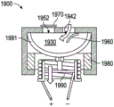
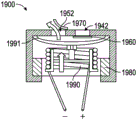
Fig. 19A-19B show cross-sectional side views of a pump assembly. The pump assembly 1900 is similar to the pump assembly 100 shown in fig. 1, except as noted below. Accordingly, the reference numbers used to designate the various components of the pump assembly 1900 are the same as the reference numbers used to identify the corresponding components of the pump assembly 100 in fig. 1, except that the reference numbers of the pump assembly 1900 begin with "19". Accordingly, descriptions of the various components for the pump assembly 100 shown in fig. 1 should be understood to apply to the corresponding components of the pump assembly 1900 in fig. 19A-19B, except as described below.
The pump assembly 1900 includes a magnet 1980, an electromagnet 1990, and a membrane 1991. Alternatively, the electromagnet 1990 may be a voice coil. In the illustrated embodiment, the membrane 1991 is connected to the electromagnet 1990 and moves with the electromagnet 1990 to expand and contract the volume of the chamber 1930 when current is delivered to the electromagnet 1990. The pump assembly 1900 has an inlet passage 1942 in fluid communication with the chamber 1930. The pump assembly 1900 has an outlet passage 1952 in fluid communication with the chamber 1930. The one-way valve 1960 allows fluid to flow into the chamber 1930 through the inlet passage 1942 but inhibits (e.g., prevents) fluid from the chamber 1930 from flowing into the inlet passage 1942 (e.g., inhibits reverse flow into the inlet passage 142). A one-way valve 1970 allows fluid to flow from the chamber 1930 and through the outlet passage 1952 but inhibits (e.g., prevents) fluid flow from the outlet passage 1952 into the chamber 1930 (e.g., inhibits reverse flow into the chamber 130). Fig. 19A shows the pump assembly 1900 in an intake position. Fig. 19B shows the pump assembly 1900 in the exhaust position.
The one- way valves 1960, 1970 may comprise a PZT material and may be adapted to open and close in response to an applied potential. In some embodiments, the piezoelectric check valves 1960, 1970 are driven separately from the electromagnet 1990. In certain variations, the piezoelectric one- way valves 1960, 1970 are driven by a square wave, while the electromagnet 1990 is driven by a sine wave. In this manner, the piezoelectric one- way valves 1960, 1970 are effectively completely decoupled from the pump drive of the electromagnet 1990 and diaphragm 1991. The piezoelectric check valves 1960, 1970 may be configured to open when a voltage is applied across each valve. In some embodiments, the valve is configured to close when no power is applied to the valve for minimum power consumption and leakage rate. In some embodiments, the square wave used to control the piezoelectric valves 1960, 1970 is in phase with the sine wave used to control the electromagnet 1990. However, in certain variations, the square wave may extend slightly farther to allow the outlet valve 1970 to close slightly after the diaphragm 1991 has reached top dead center.
The square waves used to actuate the piezoelectric check valves 1960, 1970 may be pulse width modulated and may be operated at different drive frequencies. The benefits of using this valving system are: due to the cost of the power used to drive the piezo valves 1960, 1970, the flow rate of the pump will increase. Additionally, for a given flow rate, the electromagnet 1990 can be driven at a lower amplitude, which would be more efficient. Driving the pump at a higher amplitude consumes more energy due to the increased tension of the diaphragm 1991. However, blowing open a non-check valve requires a certain pressure differential, potentially using as much power as the rest of the pump assembly. Thus, the normal electromagnet 1990 is a trade-off between the amplitude necessary to blow the valve open and the valve having the lowest viscosity to avoid valve leakage. Larger amplitudes make the inflation efficiency higher but reduce the mechanical efficiency. This trade-off can be eliminated by controlling the valving of the chamber 1930 via a piezoelectric valve, in which case the valve power cost will be fixed regardless of the amplitude of the pump diaphragm 1991. Another benefit of independent piezoelectric valving is: which allows lower amplitude "over-square" pistons to work well. A super square piston is generally characterized by large diameter, small stroke, and high frequency operation. This system would be useful for bubble-drum pump assemblies.
The PZT pump assembly described in figures 12A-19B can be incorporated into a wound dressing as described in figures 11A-11B. For example, referring to fig. 11A, the PZT pump assembly can be a pump system 5000 in fluid communication with a dressing 950A via a conduit 954A. As previously described, the pump system 5000 can be coupled to the dressing 950A (e.g., via an adhesive) such that the pump system 5000 is disposed on the dressing 950A. The pump system 5000 can include one or more pump assemblies P (such as the pump assemblies disclosed above). In some embodiments, the pump system 5000 includes an array (such as one of the arrays disclosed above). Dressing 950A may include one or more woven, non-woven foam, or super absorbent layers, or combinations thereof.
Referring to fig. 11B, the PZT pump assembly can be a pump system 6000 that is incorporated into the dressing assembly 950B. The inner conduit 954B may fluidly interconnect the pump system 6000 with the wound site (e.g., via one or more layers of the dressing 950B). The pump system 6000 may include one or more pump assemblies P (such as the pump assemblies disclosed above). In some embodiments, the pump system 6000 includes an array (such as one of the arrays disclosed above). Dressing 950B may include one or more woven, non-woven foam or super absorbent layers, or combinations thereof.
Other embodiments
Embodiments of the pump system (e.g., pump assembly, array) of the present disclosure are not limited to use with dressings or for wound therapy. Any of the embodiments of the pump systems disclosed herein can be used independently of the dressing component. Furthermore, any embodiment of the pump system disclosed herein may be used or may be adapted for other purposes than negative pressure wound therapy. Thus, any embodiment of the pump system disclosed herein may be used or may be adapted for moving fluids (gases and/or liquids) in any system or application.
Any values of thresholds, limits, durations, etc. provided herein are not intended to be absolute, and thus may be approximate. Additionally, any of the thresholds, limits, durations, etc. provided herein may be modified or changed automatically or by a user. Further, as used herein, relative terms such as exceeding, greater than, less than, etc., relative to a reference value are intended to also include being equal to the reference value. For example, exceeding a positive reference value may include being equal to or greater than the reference value. Further, as used herein, relative terms such as above, greater than, less than, and the like with respect to a reference value are intended to also encompass an inverse of the disclosed relationship, such as below, less than, greater than, and the like with respect to the reference value.
While certain embodiments have been described, these embodiments have been presented by way of example only, and are not intended to limit the scope of the present disclosure. Indeed, the novel methods and systems described herein may be embodied in a variety of other forms. Furthermore, various omissions, substitutions and changes in the systems and methods described herein may be made without departing from the spirit of the disclosure. The accompanying claims and their equivalents are intended to cover such forms or modifications as would fall within the scope and spirit of the disclosure. Accordingly, the scope of the present disclosure is to be defined only by reference to the claims presented herein or presented in the future.
Features, materials, characteristics or groups described in connection with a particular aspect, embodiment or example are to be understood as applicable to any other aspect, embodiment or example described in this section or elsewhere in this specification unless incompatible therewith. All of the features disclosed in this specification (including any accompanying claims, abstract and drawings), and/or all of the steps of any method or process so disclosed, may be combined in any combination, except combinations where at least some of such features and/or steps are mutually exclusive. The protection is not restricted to the details of any of the foregoing embodiments. Any novel one, or any novel combination, of the features disclosed in this specification (including any accompanying claims, abstract and drawings), or any novel one, or any novel combination, of the steps of any method or process so disclosed, is/are protected.
Furthermore, certain features that are described in this disclosure in the context of separate embodiments can also be implemented in combination in a single embodiment. Conversely, various features that are described in the context of a single embodiment can also be implemented in multiple embodiments separately or in any suitable subcombination. Furthermore, although features may be described above as acting in certain combinations, one or more features from a claimed combination can in some cases be excised from the combination, and the combination may be claimed as a subcombination or variation of a subcombination.
Further, while operations may be depicted in the drawings or described in the specification in a particular order, these operations need not be performed in the particular order shown or in sequential order, or all of the operations may be performed, to achieve desirable results. Other operations not depicted or described may be incorporated in the example methods and processes. For example, one or more additional operations may be performed before, after, concurrently with, or between any of the operations described. Further, operations may be rearranged or rearranged in other embodiments. Those skilled in the art will appreciate that in some embodiments, the actual steps taken in the processes shown and/or disclosed may differ from those shown in the figures. Depending on the embodiment, some of the steps described above may be removed, and other steps may be added. The various components shown in the figures may be implemented as software and/or firmware on a processor, controller, ASIC, FPGA, and/or dedicated hardware. Hardware components such as processors, ASICs, FPGAs, and the like, may include logic circuitry. Furthermore, the features and attributes of the specific embodiments disclosed above can be combined in different ways to form additional embodiments, all of which fall within the scope of the present disclosure. Moreover, the separation of various system components in the embodiments described above should not be understood as requiring such separation in all embodiments, and it should be understood that the described components and systems can generally be integrated together in a single product or packaged into multiple products.
For the purposes of this disclosure, certain aspects, advantages, and novel features are described herein. Not all of these advantages may be achieved in accordance with any particular embodiment. Thus, for example, those skilled in the art will recognize that the disclosure may be embodied or carried out in a manner that achieves one advantage or group of advantages as taught herein without necessarily achieving other advantages as may be taught or suggested herein.
Conditional language, such as "may," "can," or "may," unless expressly stated otherwise or understood otherwise in the context of usage, is generally intended to convey that certain embodiments include, while other embodiments do not include, certain features, elements, and/or steps. Thus, such conditional language is not generally intended to imply that features, elements and/or steps are in any way required for one or more embodiments or that one or more embodiments necessarily include logic for deciding, with or without user input or prompting, whether these features, elements and/or steps are included or are to be performed in any particular embodiment.
Conjunctive language such as the phrase "X, Y and at least one of Z" is also understood with the context to be used generically to express items, terms, etc. that may be X, Y or Z unless otherwise expressly stated. Thus, such conjunctive language is generally not meant to imply that certain embodiments require the presence of at least one of X, at least one of Y, and at least one of Z.
The terms "about," "generally," and "substantially," as used herein, mean a value, amount, or characteristic that is close to the recited value, amount, or characteristic, that still performs the desired function or achieves the desired result. For example, the terms "about," "generally," and "substantially" can refer to an amount that is within 10% less, within 5% less, within 1% less, within 0.1% less, and within 0.01% less than the recited amount. As another example, in certain embodiments, the terms "substantially parallel" and "substantially parallel" refer to a value, amount, or characteristic that deviates from exactly parallel by less than or equal to 15 degrees, 10 degrees, 5 degrees, 3 degrees, 1 degree, or 0.1 degrees.
The scope of the present disclosure is not intended to be limited by the specific disclosure of the preferred embodiments in this section or elsewhere in this specification, and may be defined by claims presented or presented elsewhere in this or a future. The language of the claims is to be construed broadly based on the language used in the claims and not limited to examples described in the specification or during the prosecution of the application, which examples are to be construed as non-exclusive.
Claims (46)
1. An apparatus for use in negative pressure wound therapy, comprising:
a pump system, the pump system comprising:
a pump assembly, the pump assembly comprising:
a pump chamber having an interior surface, an exterior surface, an inlet, and an outlet, the interior surface and the exterior surface defined by a first side and a second side generally opposite the first side,
a first magnetic actuator coupled to the first side of the pump chamber; and
a second magnetic actuator coupled to the second side of the pump chamber,
wherein one or both of the first and second magnetic actuators are electromagnets actuatable to generate a magnetic field that exerts a force on one or both of the first and second magnetic actuators to move the pump chamber between an intake stroke and an exhaust stroke to pump fluid through the pump chamber, both the first and second sides of the pump chamber being movable.
2. The apparatus of claim 1, wherein one or both of the first and second sides of the pump chamber comprises a material that changes shape upon application of an electrical potential.
3. The device of claim 2, wherein the material is selected from the group consisting of liquid crystals and piezoelectric crystals.
4. The apparatus of claim 2, wherein the potential is a variable potential having a frequency between 16kHz and 80 kHz.
5. The apparatus of claim 2, wherein one or both of the first and second sides of the pump chamber move between the intake stroke and the exhaust stroke at a frequency between 16kHz and 80 kHz.
6. The apparatus of claim 2, wherein the pump assembly has an outlet passage having a first cross-sectional area when the pump chamber is in the intake stroke and a second cross-sectional area when the pump chamber is in the exhaust stroke, a ratio of the first cross-sectional area to the second cross-sectional area being between 0.03 and 0.8.
7. The apparatus of claim 2, wherein one or both of the first and second sides of the pump chamber at least partially define one or more intake openings and one or more exhaust openings, wherein movement of the pump chamber to the intake stroke substantially closes the one or more exhaust openings to inhibit fluid flow therethrough while allowing fluid to pass through the one or more intake openings, and wherein movement of the pump chamber to the exhaust stroke substantially closes the one or more intake openings to inhibit fluid flow therethrough while allowing the fluid to exit the pump chamber via the one or more exhaust openings.
8. The apparatus of claim 1, further comprising a power source configured to supply current to the electromagnet to generate the magnetic field.
9. The apparatus of claim 1, wherein the pump assembly comprises one or more one-way valves positioned along a flow path between the inlet and the outlet of the pump chamber.
10. The apparatus of claim 9, wherein at least one of the one or more one-way valves is in an inlet portion of the pump assembly in fluid communication with the pump chamber, the one-way valve configured to allow flow into the pump chamber through an inlet flow passage and inhibit reverse flow from the pump chamber into the inlet portion.
11. The apparatus of claim 9, wherein at least one of the one or more one-way valves is in an outlet portion of the pump assembly in fluid communication with the pump chamber, the one-way valve configured to allow flow from the pump chamber into the outlet portion through an outlet flow passage and inhibit reverse flow from the outlet portion into the pump chamber.
12. The apparatus of any of claims 8 to 11, wherein the pump chamber is defined by first and second diaphragms made of a flexible material and configured to move toward each other when the pump chamber is moved to a collapsed position and away from each other when the pump chamber is moved to an extended position.
13. The apparatus of claim 12, wherein the first and second diaphragms are sealed along their respective edges.
14. The apparatus of claim 12, wherein the first and second membranes are sealed via an adhesive.
15. The apparatus of claim 12, wherein the first and second diaphragms are sealed by welding.
16. The apparatus of any of claims 8-11, wherein the first and second magnetic actuators are coupled to an interior surface of the pump chamber.
17. The apparatus of any one of claims 8 to 11, wherein the electromagnet is a voice coil.
18. The apparatus of any of claims 8 to 11, wherein one or both of the first and second magnetic actuators are printed, electrostatically deposited or coated onto the interior surfaces of the first and second sides of the pump chamber.
19. The apparatus of any of claims 8 to 11, wherein the first magnetic actuator comprises one or more electromagnets and the second magnetic actuator comprises one or more permanent magnets.
20. The apparatus of any of claims 19, wherein the one or more permanent magnets have an annular shape with an inner diameter and an outer diameter, and wherein the one or more electromagnets are coils with an inner diameter and an outer diameter.
21. The apparatus of claim 20, wherein the inner diameter of the permanent magnet is larger than an outer diameter of the coil, thereby allowing the coil to extend at least partially into the opening of the permanent magnet during operation of the pump assembly.
22. The apparatus of claim 20, wherein the outer diameter of the permanent magnet is smaller than an inner diameter of the coil, thereby allowing the coil to extend at least partially over the permanent magnet during operation of the pump assembly.
23. The apparatus of claim 19, wherein the permanent magnet is a plate.
24. The apparatus of any of claims 8 to 11, wherein both the first and second magnetic actuators comprise electromagnets.
25. The apparatus of claim 24, wherein the electromagnets are coils, an inner diameter of one of the coils being larger than an outer diameter of the other of the coils, thereby allowing the other of the coils to extend at least partially into an opening of the one of the coils during operation of the pump assembly.
26. The apparatus of claim 24, wherein the electromagnet of the first magnetic actuator and the electromagnet of the second magnetic actuator are oppositely wound along a longitudinal axis of the electromagnets, the electromagnet of the first magnetic actuator configured to be supplied with electrical current in a first phase, and the electromagnet of the second magnetic actuator configured to be supplied with electrical current in a second phase different from the first phase to operate the pump assembly.
27. The apparatus of claim 24, wherein the electromagnets of the first and second magnetic actuators are connected in series.
28. The apparatus of claim 24, wherein the electromagnets of the first and second magnetic actuators are connected in parallel.
29. The apparatus of any one of claims 8 to 11, further comprising a second pump assembly having the same structure as the pump assembly.
30. The apparatus of claim 29, wherein the pump assembly and the second pump assembly are fluidly coupled in series.
31. The apparatus of claim 30, wherein the pump assembly operates in a first phase and the second pump assembly operates in a second phase opposite the first phase to facilitate movement of fluid through the pump system.
32. The apparatus of claim 29, wherein the pump assembly and the second pump assembly are fluidly coupled in parallel.
33. The apparatus of claim 32, wherein the pump assembly and second pump assembly operate in the same phase.
34. The apparatus of claim 32, wherein the pump assembly and second pump assembly are arranged in separate layers one on top of the other, the pump assembly operating in a first phase and the second pump assembly operating in a second phase opposite the first phase to facilitate movement of fluid through the pump system.
35. A combination of the apparatus of any one of claims 8-34 and a wound dressing, wherein the pump system is configured to pump fluid from the wound dressing during negative pressure wound therapy.
36. The combination of claim 35, wherein the apparatus is separate from the wound dressing and the apparatus is fluidly coupled to the wound dressing via a conduit.
37. The combination of claim 35, wherein the device is attached to the top side of the wound dressing with an adhesive.
38. A wound dressing for use in negative pressure wound therapy, comprising:
a dressing body comprising one or more layers and configured to be removably disposed over a wound site; and
one or more pump assemblies disposed on and fluidly coupled to at least one of the one or more layers and configured to pump fluid from the wound site, each of the one or more pump assemblies comprising:
a pump chamber having an interior surface, an inlet, and an outlet, the interior surface defined by a first side and a second side generally opposite the first side;
a first magnetic actuator coupled to the interior surface of the first side of the pump chamber; and
a second magnetic actuator coupled to the interior surface of the second side of the pump chamber,
wherein one or both of the first and second magnetic actuators are electromagnets actuatable to generate a magnetic field that exerts a force on one of the first and second magnetic actuators to move the pump chamber between an extended position and a collapsed position to pump fluid through the pump chamber, both the first and second sides of the pump chamber being movable.
39. The wound dressing of claim 38, wherein the pump chamber is defined by first and second diaphragms made of a flexible material and configured to move toward each other when the pump chamber is moved to the collapsed position and away from each other when the pump chamber is moved to the extended position.
40. The wound dressing of claim 39, wherein the flexible material is foam.
41. The wound dressing of claim 39, wherein the first and second membranes are sealed along their respective edges.
42. The wound dressing of claim 38, wherein the pump assembly comprises one or more one-way valves positioned along a flow path between the inlet and the outlet of the pump chamber.
43. The wound dressing of claim 42, wherein at least one of the one or more one-way valves is in an inlet portion of the pump assembly in fluid communication with the pump chamber, the one-way valve configured to allow flow into the pump chamber through an inlet flow passage and inhibit reverse flow from the pump chamber into the inlet portion.
44. The wound dressing of claim 42, wherein at least one of the one or more one-way valves is in an outlet portion of the pump assembly in fluid communication with the pump chamber, the one-way valve configured to allow flow from the pump chamber into the outlet portion through an outlet flow passage and inhibit reverse flow from the outlet portion into the pump chamber.
45. The wound dressing of any one of claims 42-44, wherein at least one of the one or more one-way valves comprises a material that swells upon contact with liquid, thereby allowing the one or more pump assemblies to be operated to stop upon the dressing body becoming full of wound exudate.
46. The wound dressing of any one of claims 38-44, wherein the one or more pump assemblies are fluidly coupled to at least one of the one or more layers by a conduit.
Applications Claiming Priority (5)
| Application Number | Priority Date | Filing Date | Title |
|---|---|---|---|
| US201562163170P | 2015-05-18 | 2015-05-18 | |
| US62/163170 | 2015-05-18 | ||
| US201662332411P | 2016-05-05 | 2016-05-05 | |
| US62/332411 | 2016-05-05 | ||
| PCT/EP2016/061139 WO2016184913A1 (en) | 2015-05-18 | 2016-05-18 | Negative pressure wound therapy apparatus and methods |
Publications (2)
| Publication Number | Publication Date |
|---|---|
| CN107580509A CN107580509A (en) | 2018-01-12 |
| CN107580509B true CN107580509B (en) | 2021-06-15 |
Family
ID=57319499
Family Applications (1)
| Application Number | Title | Priority Date | Filing Date |
|---|---|---|---|
| CN201680028863.7A Active CN107580509B (en) | 2015-05-18 | 2016-05-18 | Negative pressure wound therapy apparatus and method |
Country Status (5)
| Country | Link |
|---|---|
| US (1) | US10973693B2 (en) |
| EP (1) | EP3297697B1 (en) |
| JP (1) | JP6812363B2 (en) |
| CN (1) | CN107580509B (en) |
| WO (1) | WO2016184913A1 (en) |
Families Citing this family (22)
| Publication number | Priority date | Publication date | Assignee | Title |
|---|---|---|---|---|
| US9421132B2 (en) | 2011-02-04 | 2016-08-23 | University Of Massachusetts | Negative pressure wound closure device |
| AU2013264937B2 (en) | 2012-05-24 | 2018-04-19 | Smith & Nephew Inc. | Devices and methods for treating and closing wounds with negative pressure |
| JP6353445B2 (en) | 2012-07-16 | 2018-07-04 | スミス アンド ネフュー インコーポレイテッド | Negative pressure wound closure device |
| AU2014248519B2 (en) | 2013-03-13 | 2018-12-20 | Smith & Nephew Inc. | Negative pressure wound closure device and systems and methods of use in treating wounds with negative pressure |
| AU2016254119A1 (en) | 2015-04-29 | 2017-10-05 | Smith & Nephew Inc. | Negative pressure wound closure device |
| GB2557143B (en) | 2015-08-13 | 2021-01-06 | Smith & Nephew Inc | Systems and methods for applying reduced pressure therapy |
| US10575991B2 (en) | 2015-12-15 | 2020-03-03 | University Of Massachusetts | Negative pressure wound closure devices and methods |
| WO2018237206A2 (en) * | 2017-06-21 | 2018-12-27 | University Of Massachusetts | Negative pressure wound closure devices and methods |
| US10814049B2 (en) | 2015-12-15 | 2020-10-27 | University Of Massachusetts | Negative pressure wound closure devices and methods |
| US11471586B2 (en) | 2015-12-15 | 2022-10-18 | University Of Massachusetts | Negative pressure wound closure devices and methods |
| BR112019000284A2 (en) | 2016-07-08 | 2019-04-16 | Convatec Technologies Inc. | fluid collection apparatus |
| CN110709113A (en) | 2017-02-15 | 2020-01-17 | 新加坡施乐辉有限公司 | Negative pressure wound therapy device and method of use thereof |
| EP3585453B1 (en) | 2017-02-22 | 2023-05-17 | Cornell University | Mechanical vacuum dressing for mechanically managing, protecting and suctioning small incisional wounds |
| WO2019063467A1 (en) | 2017-09-29 | 2019-04-04 | T.J.Smith And Nephew,Limited | Negative pressure wound therapy apparatus with removable panels |
| EP3720518A4 (en) | 2017-12-06 | 2021-09-15 | Cornell University | Manually-operated negative pressure wound therapy (npwt) bandage with improved pump efficiency, automatic pressure indicator and automatic pressure limiter |
| GB201813282D0 (en) | 2018-08-15 | 2018-09-26 | Smith & Nephew | System for medical device activation and opertion |
| US10624794B2 (en) | 2018-02-12 | 2020-04-21 | Healyx Labs, Inc. | Negative pressure wound therapy systems, devices, and methods |
| GB201804347D0 (en) | 2018-03-19 | 2018-05-02 | Smith & Nephew Inc | Securing control of settings of negative pressure wound therapy apparatuses and methods for using the same |
| GB201806988D0 (en) | 2018-04-30 | 2018-06-13 | Quintanar Felix Clarence | Power source charging for negative pressure wound therapy apparatus |
| WO2019211731A1 (en) | 2018-04-30 | 2019-11-07 | Smith & Nephew Pte. Limited | Systems and methods for controlling dual mode negative pressure wound therapy apparatus |
| GB201808438D0 (en) | 2018-05-23 | 2018-07-11 | Smith & Nephew | Systems and methods for determining blockages in a negative pressure wound therapy system |
| GB201914427D0 (en) * | 2019-10-07 | 2019-11-20 | Smith & Nephew | Negative pressure wound therapy systems and methods with multiple negative pressure sources |
Family Cites Families (138)
| Publication number | Priority date | Publication date | Assignee | Title |
|---|---|---|---|---|
| FR1535489A (en) * | 1967-04-21 | 1968-08-09 | Improvements to DC motors without a commutator and some devices that use them | |
| JPS5647279U (en) * | 1979-09-20 | 1981-04-27 | ||
| JPS5647279A (en) | 1979-09-27 | 1981-04-28 | Daihen Corp | Co2 gas shielded arc welding |
| IL59942A (en) * | 1980-04-28 | 1986-08-31 | D P Lab Ltd | Method and device for fluid transfer |
| US5527274A (en) | 1986-06-09 | 1996-06-18 | Development Collaborative Corporation | Catheter for chemical contact dissolution of gallstones |
| US4731076A (en) * | 1986-12-22 | 1988-03-15 | Baylor College Of Medicine | Piezoelectric fluid pumping system for use in the human body |
| JPH01101978A (en) | 1987-10-15 | 1989-04-19 | Japan Medical Dynamic Marketing Inc | Flow rate changeable cerebral ventricle shunt |
| SE508435C2 (en) * | 1993-02-23 | 1998-10-05 | Erik Stemme | Diaphragm pump type pump |
| USD357735S (en) | 1993-08-03 | 1995-04-25 | I-Flow Corporation | Valve for filling an IV solution bag |
| JPH0796029A (en) | 1993-09-30 | 1995-04-11 | Nippon Zeon Co Ltd | Bile reflux catheter |
| EP1219311B1 (en) | 1994-08-22 | 2004-07-07 | Kinetic Concepts, Inc. | Canister |
| US5712795A (en) | 1995-10-02 | 1998-01-27 | Alaris Medical Systems, Inc. | Power management system |
| EP0883430B1 (en) | 1995-10-20 | 2007-01-03 | Haemonetics Corporation | Connector cartridge |
| EP0959910A4 (en) | 1996-01-24 | 2000-03-01 | Fred R Radford | Contaminated medical waste disposal system and method |
| US7214202B1 (en) | 1997-07-28 | 2007-05-08 | Kci Licensing, Inc. | Therapeutic apparatus for treating ulcers |
| US6682500B2 (en) * | 1998-01-29 | 2004-01-27 | David Soltanpour | Synthetic muscle based diaphragm pump apparatuses |
| KR20000050679A (en) * | 1999-01-13 | 2000-08-05 | 윤종용 | Heat sinking apparatus for electronic equipment |
| EP2255837B2 (en) | 1999-04-09 | 2020-07-29 | KCI Licensing, Inc. | Process for making a porous pad for use in a wound therapy device |
| JP3666307B2 (en) | 1999-06-30 | 2005-06-29 | 松下電器産業株式会社 | Portable electronic device having a method for displaying the remaining amount of secondary battery and a method for displaying the remaining amount of secondary battery |
| US6824533B2 (en) | 2000-11-29 | 2004-11-30 | Hill-Rom Services, Inc. | Wound treatment apparatus |
| US20020098097A1 (en) * | 2001-01-22 | 2002-07-25 | Angad Singh | Magnetically-actuated micropump |
| US7070584B2 (en) | 2001-02-20 | 2006-07-04 | Kci Licensing, Inc. | Biocompatible wound dressing |
| EP1406567B1 (en) | 2001-07-12 | 2010-04-28 | KCI Medical Resources | Control of vacuum rate of change |
| US7004915B2 (en) | 2001-08-24 | 2006-02-28 | Kci Licensing, Inc. | Negative pressure assisted tissue treatment system |
| EP2317639A1 (en) * | 2002-03-18 | 2011-05-04 | SRI International | Electroactive polymer devices for moving fluid |
| USD475132S1 (en) | 2002-06-26 | 2003-05-27 | Kci Licensing, Inc. | Wound drainage canister |
| US20040068224A1 (en) | 2002-10-02 | 2004-04-08 | Couvillon Lucien Alfred | Electroactive polymer actuated medication infusion pumps |
| US20090216205A1 (en) * | 2003-08-08 | 2009-08-27 | Biodrain Medical, Inc. | Fluid waste collection and disposal system and method |
| US20050065471A1 (en) * | 2003-09-23 | 2005-03-24 | Charles Kuntz | Continuous safe suction device |
| US8038639B2 (en) | 2004-11-04 | 2011-10-18 | Baxter International Inc. | Medical fluid system with flexible sheeting disposable unit |
| US8062272B2 (en) | 2004-05-21 | 2011-11-22 | Bluesky Medical Group Incorporated | Flexible reduced pressure treatment appliance |
| EP1722412B1 (en) * | 2005-05-02 | 2012-08-29 | Sony Corporation | Jet generator and electronic device |
| US7857806B2 (en) | 2005-07-14 | 2010-12-28 | Boehringer Technologies, L.P. | Pump system for negative pressure wound therapy |
| US7608066B2 (en) | 2005-08-08 | 2009-10-27 | Innovative Therapies, Inc. | Wound irrigation device pressure monitoring and control system |
| JP2007218241A (en) | 2006-01-20 | 2007-08-30 | Sony Corp | Vibration actuator, jet stream generating apparatus, and electronic apparatus |
| EP2145636B1 (en) | 2006-05-09 | 2016-04-27 | Medela Holding AG | Suction Pump Unit |
| EP2066365B1 (en) | 2006-09-26 | 2015-04-15 | Boehringer Technologies L.P. | Pump system for negative pressure wound therapy |
| ES2564519T3 (en) | 2006-10-13 | 2016-03-23 | Bluesky Medical Group Inc. | Pressure control of a medical vacuum pump |
| KR101114653B1 (en) | 2007-02-20 | 2012-06-13 | 케이씨아이 라이센싱 인코포레이티드 | Apparatus and method for distinguishing leaks from a disengaged canister condition in a reduced pressure treatment apparatus |
| AU2008246934A1 (en) | 2007-05-07 | 2008-11-13 | Carmeli Adahan | Suction system |
| USD581042S1 (en) | 2007-05-11 | 2008-11-18 | Kci Licensing, Inc. | Reduced pressure treatment system |
| USD590934S1 (en) | 2007-05-11 | 2009-04-21 | Kci Licensing, Inc. | Reduced pressure treatment system |
| JP5290630B2 (en) | 2007-06-05 | 2013-09-18 | ニプロ株式会社 | Medical connector and manufacturing method thereof |
| GB0712758D0 (en) | 2007-07-02 | 2007-08-08 | Smith & Nephew | Battery recharging |
| USD602583S1 (en) | 2007-07-02 | 2009-10-20 | Smith & Nephew Plc | Device for applying negative pressure to a wound |
| USD602584S1 (en) | 2007-07-02 | 2009-10-20 | Smith & Nephew Plc | Canister |
| GB0712739D0 (en) | 2007-07-02 | 2007-08-08 | Smith & Nephew | Apparatus |
| USD602582S1 (en) | 2007-07-02 | 2009-10-20 | Smith & Nephew LLC | Therapy unit assembly |
| USD654164S1 (en) | 2007-07-12 | 2012-02-14 | Talley Group Limited | Wound drainage apparatus for medical purposes |
| EP2180907A4 (en) | 2007-08-17 | 2017-07-26 | ConvaTec Technologies Inc. | Aspiration system for removing liquid discharged by the human body, and liquid sensor therefor |
| TWI340653B (en) * | 2007-11-09 | 2011-04-21 | Ind Tech Res Inst | Detachable pump and the negative pressure wound therapy system using the same |
| GB0723855D0 (en) | 2007-12-06 | 2008-01-16 | Smith & Nephew | Apparatus and method for wound volume measurement |
| US8366692B2 (en) | 2008-01-08 | 2013-02-05 | Richard Scott Weston | Sustained variable negative pressure wound treatment and method of controlling same |
| CA2726814C (en) | 2008-05-27 | 2014-05-20 | Kalypto Medical, Inc. | Control unit with pump module for a negative pressure wound therapy device |
| EP2303359B1 (en) | 2008-05-29 | 2020-02-26 | Roche Diabetes Care GmbH | Modular medical infusion device with means for identification/authentication between its components |
| EP3073114B1 (en) * | 2008-06-03 | 2018-07-25 | Murata Manufacturing Co., Ltd. | Piezoelectric micro-blower |
| CA2765419C (en) | 2008-06-13 | 2017-10-24 | Premco Medical Systems, Inc. | Wound treatment apparatus and method |
| USD660409S1 (en) | 2008-10-24 | 2012-05-22 | Talley Group Limited | Compact negative pressure wound treatment apparatus |
| EP2340060B1 (en) | 2008-10-29 | 2017-01-25 | KCI Licensing, Inc. | Medical canister connectors |
| US8226601B2 (en) | 2008-11-12 | 2012-07-24 | Sanovas, Inc. | Resector balloon system |
| FR2939320B1 (en) | 2008-12-05 | 2010-12-31 | Ind Tech Res Inst | DETACHABLE PUMP AND NEGATIVE PRESSURE WOUND TREATMENT SYSTEM USING THE SAME. |
| US8882678B2 (en) | 2009-03-13 | 2014-11-11 | Atrium Medical Corporation | Pleural drainage system and method of use |
| US8344847B2 (en) | 2009-07-09 | 2013-01-01 | Medtronic Minimed, Inc. | Coordination of control commands in a medical device system having at least one therapy delivery device and at least one wireless controller device |
| DE102009038130A1 (en) | 2009-08-12 | 2011-02-17 | ATMOS Medizin Technik GmbH & Co. KG | A user portable device for providing negative pressure for medical applications |
| CH702195A1 (en) | 2009-11-05 | 2011-05-13 | Medela Holding Ag | Drainage pump unit |
| USD645137S1 (en) | 2009-12-04 | 2011-09-13 | Smith & Nephew Plc | Canister |
| EP2513480A1 (en) | 2009-12-18 | 2012-10-24 | K&Y Corporation | Infusion pump |
| US8066243B2 (en) | 2010-01-08 | 2011-11-29 | Richard C. Vogel | Adapter for portable negative pressure wound therapy device |
| US8394081B2 (en) | 2010-01-29 | 2013-03-12 | Kci Licensing, Inc. | Wound treatment apparatuses and methods for controlled delivery of fluids to a wound |
| DE102010007464B4 (en) | 2010-02-10 | 2016-09-29 | Fresenius Medical Care Deutschland Gmbh | Medical functional device, treatment device and method |
| CH702650A1 (en) | 2010-02-11 | 2011-08-15 | Medela Holding Ag | Apparatus and method for detecting couplings between two system components. |
| US8641693B2 (en) | 2010-05-18 | 2014-02-04 | Kci Licensing, Inc. | Reduced-pressure canisters and methods for recycling |
| US8409160B2 (en) * | 2010-05-18 | 2013-04-02 | Kci Licensing, Inc. | Reduced-pressure treatment systems and methods employing a fluidly isolated pump control unit |
| WO2012004298A1 (en) | 2010-07-06 | 2012-01-12 | Novo Nordisk A/S | System for indicating lifetime status for medical component |
| GB201015656D0 (en) | 2010-09-20 | 2010-10-27 | Smith & Nephew | Pressure control apparatus |
| CH704072A1 (en) | 2010-11-15 | 2012-05-15 | Medela Holding Ag | Portable Absaugpumpeinheit |
| CH704423A1 (en) | 2011-01-17 | 2012-07-31 | Medela Holding Ag | Drainage pump unit. |
| CN102068750B (en) | 2011-01-26 | 2013-05-15 | 惠州市华阳医疗电子有限公司 | System equipment management-based negative pressure wound therapy system |
| USD788293S1 (en) | 2011-03-03 | 2017-05-30 | Paul Hartmann Ag | Vacuum generating device |
| JP5502017B2 (en) * | 2011-04-15 | 2014-05-28 | 株式会社テクノ高槻 | Electromagnetic vibration type diaphragm pump |
| DE102011075842A1 (en) | 2011-05-13 | 2012-11-15 | Paul Hartmann Ag | Device for providing negative pressure for medical negative pressure treatment of wounds |
| BR112014001884A2 (en) | 2011-07-26 | 2019-10-15 | Smith & Nephew | systems and methods for controlling the operation of a reduced pressure therapy system |
| EP2755696B1 (en) | 2011-09-13 | 2016-04-06 | KCI Licensing, Inc. | Reduced-pressure canisters having hydrophobic pores |
| USD707355S1 (en) | 2011-09-29 | 2014-06-17 | Medline Industries, Inc. | Connector |
| US9084845B2 (en) | 2011-11-02 | 2015-07-21 | Smith & Nephew Plc | Reduced pressure therapy apparatuses and methods of using same |
| US10155071B2 (en) | 2011-11-23 | 2018-12-18 | Kci Licensing, Inc. | Reduced-pressure systems, methods, and devices for simultaneously treating a plurality of tissue sites |
| WO2013140255A1 (en) | 2012-03-20 | 2013-09-26 | Smith & Nephew Plc | Controlling operation of a reduced pressure therapy system based on dynamic duty cycle threshold determination |
| US20180021178A1 (en) | 2012-03-28 | 2018-01-25 | Kci Licensing, Inc. | Reduced-Pressure Systems, Dressings, Pump Assemblies And Methods |
| CN103357076A (en) | 2012-04-05 | 2013-10-23 | 戴闻医疗产品奥克维尔分销公司 | Power saving control system for negative pressure wound therapy pumps |
| US8858517B2 (en) | 2012-04-05 | 2014-10-14 | Oakwell Distribution, Inc. | Power saving control system for negative pressure wound therapy pumps |
| US9095644B2 (en) | 2012-04-13 | 2015-08-04 | Apex Medical Corp. | Fluid collector |
| US9427505B2 (en) | 2012-05-15 | 2016-08-30 | Smith & Nephew Plc | Negative pressure wound therapy apparatus |
| GB201216928D0 (en) | 2012-09-21 | 2012-11-07 | I2R Medical Ltd | Portable medical device system |
| EP2711033A1 (en) | 2012-09-25 | 2014-03-26 | Paul Hartmann AG | System for wound treatment |
| US9199010B2 (en) | 2012-11-26 | 2015-12-01 | Apex Medical Corp. | Wound drainage therapy system |
| JP2016054748A (en) | 2013-01-24 | 2016-04-21 | Lwj株式会社 | Artificial heart unit, artificial heart, and magnet unit |
| EP2968700B1 (en) | 2013-03-13 | 2019-07-24 | KCI Licensing, Inc. | Collapsible canister for use with reduced pressure therapy device |
| WO2014164655A1 (en) | 2013-03-13 | 2014-10-09 | Thermedx, Llc | Fluid management system |
| USD764654S1 (en) | 2014-03-13 | 2016-08-23 | Smith & Nephew, Inc. | Canister for collecting wound exudate |
| US9737649B2 (en) | 2013-03-14 | 2017-08-22 | Smith & Nephew, Inc. | Systems and methods for applying reduced pressure therapy |
| US9415199B2 (en) | 2013-06-14 | 2016-08-16 | Skill Partner Limited | Leak proof needleless medical connector |
| EP3854442A1 (en) | 2013-07-03 | 2021-07-28 | DEKA Products Limited Partnership | Fluid connector assembly |
| AU2014306876B2 (en) | 2013-08-13 | 2019-05-02 | Smith & Nephew, Inc. | Systems and methods for applying reduced pressure therapy |
| USD730518S1 (en) | 2013-09-12 | 2015-05-26 | Nordson Corporation | Quick connect fluid connector |
| USD746446S1 (en) | 2013-11-25 | 2015-12-29 | Medline Industries, Inc. | Connector |
| DE102013226713A1 (en) | 2013-12-19 | 2015-06-25 | Paul Hartmann Ag | System for combined vacuum and instillation treatment of wounds |
| WO2015115516A1 (en) | 2014-01-30 | 2015-08-06 | 株式会社村田製作所 | Suction device |
| US10188581B2 (en) | 2014-02-20 | 2019-01-29 | Kci Licensing, Inc. | Method and system to evacuate one or more dressings using two or more vacuum pumps |
| USD750235S1 (en) | 2014-03-19 | 2016-02-23 | ERBE-USA, Inc. | Endoscope connector |
| USD750236S1 (en) | 2014-03-19 | 2016-02-23 | ERBE-USA, Inc. | Endoscope connector |
| AU359280S (en) | 2014-04-30 | 2014-12-08 | Talley Group Ltd | Negative pressure wound therapy pump |
| USD764047S1 (en) | 2014-05-28 | 2016-08-16 | Smith & Nephew, Inc. | Therapy unit assembly |
| USD764048S1 (en) | 2014-05-28 | 2016-08-16 | Smith & Nephew, Inc. | Device for applying negative pressure to a wound |
| USD764653S1 (en) | 2014-05-28 | 2016-08-23 | Smith & Nephew, Inc. | Canister for collecting wound exudate |
| USD765830S1 (en) | 2014-06-02 | 2016-09-06 | Smith & Nephew, Inc. | Therapy unit assembly |
| EP2959926A1 (en) | 2014-06-26 | 2015-12-30 | Medela Holding AG | Medical suction pump and fluid-collection container |
| EP3851134A1 (en) | 2014-07-18 | 2021-07-21 | 3M Innovative Properties Company | Disposable cartridge for vacuum actuated fluid delivery |
| USD784529S1 (en) | 2014-07-31 | 2017-04-18 | Nordson Corporation | Enteral feeding connector assembly |
| JP6644764B2 (en) | 2014-07-31 | 2020-02-12 | スミス アンド ネフュー インコーポレイテッド | Systems and methods for delivering decompression therapy |
| KR102267626B1 (en) | 2014-11-20 | 2021-06-22 | 삼성전자주식회사 | Electronic device and method for managementting bettertyby the electronic device |
| JP6725528B2 (en) | 2014-12-22 | 2020-07-22 | スミス アンド ネフュー ピーエルシーSmith & Nephew Public Limited Company | Device and method for negative pressure wound therapy |
| WO2016109048A1 (en) | 2014-12-30 | 2016-07-07 | Smith & Nephew, Inc. | Systems and methods for applying reduced pressure therapy |
| EP3240587B1 (en) | 2014-12-30 | 2020-05-27 | Smith & Nephew, Inc | Systems for applying reduced pressure therapy |
| US9901672B2 (en) | 2015-01-26 | 2018-02-27 | Becton, Dickinson And Company | Smart portable infusion pump |
| US11179506B2 (en) | 2015-02-27 | 2021-11-23 | Cork Medical, Llc | Negative pressure wound therapy pump and canister |
| USD750222S1 (en) | 2015-04-27 | 2016-02-23 | Koge Micro Tech Co., Ltd | Wound therapy device |
| USD792586S1 (en) | 2015-05-18 | 2017-07-18 | Fresenius Kabi Deutschland Gmbh | Enteral feeding connector female component |
| EP3124060B1 (en) | 2015-07-28 | 2019-09-11 | Paul Hartmann AG | Silencer for a vacuum therapy unit |
| EP3124059B1 (en) | 2015-07-28 | 2018-12-05 | Paul Hartmann AG | Silencer for a vacuum therapy unit |
| DE102015215165A1 (en) | 2015-08-07 | 2017-02-09 | Asskea Gmbh | Modular device for suctioning a Absaugguts |
| GB2557143B (en) | 2015-08-13 | 2021-01-06 | Smith & Nephew Inc | Systems and methods for applying reduced pressure therapy |
| WO2017044138A1 (en) | 2015-09-11 | 2017-03-16 | Smith & Nephew, Inc. | Systems and methods for applying reduced negative pressure therapy |
| AU2015411394B2 (en) | 2015-10-07 | 2021-07-08 | Smith & Nephew, Inc. | Systems and methods for applying reduced pressure therapy |
| WO2017087785A1 (en) | 2015-11-20 | 2017-05-26 | Tc1 Llc | Energy management of blood pump controllers |
| US10500389B2 (en) | 2016-01-04 | 2019-12-10 | Repro-Med Systems, Inc. | System and method for flared luer connector for medical tubing |
| WO2017160412A1 (en) | 2016-03-17 | 2017-09-21 | Kci Licensing, Inc. | Systems and methods for treating a tissue site using one manifold and multiple therapy units |
| WO2017192810A1 (en) | 2016-05-04 | 2017-11-09 | Parasol Medical LLC | Portable pump for negative pressure wound therapy |
| EP3454917B1 (en) | 2016-05-13 | 2022-04-06 | Smith & Nephew, Inc | Automatic wound coupling detection in negative pressure wound therapy systems |
-
2016
- 2016-05-18 US US15/574,790 patent/US10973693B2/en active Active
- 2016-05-18 JP JP2017560202A patent/JP6812363B2/en active Active
- 2016-05-18 CN CN201680028863.7A patent/CN107580509B/en active Active
- 2016-05-18 WO PCT/EP2016/061139 patent/WO2016184913A1/en active Application Filing
- 2016-05-18 EP EP16723138.0A patent/EP3297697B1/en active Active
Also Published As
| Publication number | Publication date |
|---|---|
| CN107580509A (en) | 2018-01-12 |
| WO2016184913A1 (en) | 2016-11-24 |
| US10973693B2 (en) | 2021-04-13 |
| JP6812363B2 (en) | 2021-01-13 |
| US20180140466A1 (en) | 2018-05-24 |
| EP3297697B1 (en) | 2022-05-11 |
| EP3297697A1 (en) | 2018-03-28 |
| JP2018515260A (en) | 2018-06-14 |
Similar Documents
| Publication | Publication Date | Title |
|---|---|---|
| CN107580509B (en) | Negative pressure wound therapy apparatus and method | |
| JP7337033B2 (en) | Decompression device and method | |
| JP6911043B2 (en) | Wound healing devices and methods in which the negative pressure source is integrated within the wound dressing | |
| AU2012243056B2 (en) | Evaporative fluid pouch and systems for use with body fluids | |
| CN104066990B (en) | Disc pump with advanced actuator | |
| JP5969936B2 (en) | Anisotropic drapes and systems | |
| JP2018515260A5 (en) | ||
| EP2427228B1 (en) | Multiple segmented peristaltic pump and cassette | |
| KR20110083709A (en) | Reduced-pressure, wound-treatment dressings and systems | |
| JP2014526654A (en) | Dual cavity pump | |
| EP3292304B1 (en) | Miniature vacuum/pressure diaphragm pumps with noise mitigation boot | |
| US20070085449A1 (en) | Electro-active valveless pump | |
| US20240091431A1 (en) | Negative pressure wound therapy systems and methods with multiple negative pressure sources | |
| JP2005214138A (en) | Fluid conveying device | |
| WO2022234476A3 (en) | Liquid displacing device and a non-return valve | |
| CN102338069A (en) | Electric actuating artificial muscular pump and control method thereof |
Legal Events
| Date | Code | Title | Description |
|---|---|---|---|
| PB01 | Publication | ||
| PB01 | Publication | ||
| SE01 | Entry into force of request for substantive examination | ||
| SE01 | Entry into force of request for substantive examination | ||
| CB02 | Change of applicant information |
Address after: Hertfordshire Applicant after: Smith & Nephew PLC Address before: London, England Applicant before: Smith & Nephew PLC |
|
| CB02 | Change of applicant information | ||
| GR01 | Patent grant | ||
| GR01 | Patent grant |