JP2007218241A - Vibration actuator, jet stream generating apparatus, and electronic apparatus - Google Patents
Vibration actuator, jet stream generating apparatus, and electronic apparatus Download PDFInfo
- Publication number
- JP2007218241A JP2007218241A JP2006140309A JP2006140309A JP2007218241A JP 2007218241 A JP2007218241 A JP 2007218241A JP 2006140309 A JP2006140309 A JP 2006140309A JP 2006140309 A JP2006140309 A JP 2006140309A JP 2007218241 A JP2007218241 A JP 2007218241A
- Authority
- JP
- Japan
- Prior art keywords
- chamber
- coil
- magnet
- vibrating body
- outside
- Prior art date
- Legal status (The legal status is an assumption and is not a legal conclusion. Google has not performed a legal analysis and makes no representation as to the accuracy of the status listed.)
- Pending
Links
Images


Classifications
-
- H—ELECTRICITY
- H01—ELECTRIC ELEMENTS
- H01L—SEMICONDUCTOR DEVICES NOT COVERED BY CLASS H10
- H01L2924/00—Indexing scheme for arrangements or methods for connecting or disconnecting semiconductor or solid-state bodies as covered by H01L24/00
- H01L2924/0001—Technical content checked by a classifier
- H01L2924/0002—Not covered by any one of groups H01L24/00, H01L24/00 and H01L2224/00
Abstract
Description
本発明は、気体の合成噴流を発生する噴流発生装置、この噴流発生装置に用いられる振動アクチュエータ及び噴流発生装置を搭載した電子機器に関する。 The present invention relates to a jet generating device that generates a synthetic jet of gas, a vibration actuator used in the jet generating device, and an electronic apparatus equipped with the jet generating device.
従来から、PC(Personal Computer)の高性能化に伴うIC(Integrated Circuit)等の発熱体からの発熱量の増大が問題となっており、様々な放熱の技術が提案され、あるいは製品化されている。 Conventionally, an increase in the amount of heat generated from a heating element such as an IC (Integrated Circuit) associated with high performance of a PC (Personal Computer) has been a problem, and various heat radiation technologies have been proposed or commercialized. Yes.
その放熱方法として、空気を脈流で吐出して合成噴流を生成し、この合成噴流を、放熱フィン(ヒートシンク)等に供給し、熱を持つ放熱フィンの表面に形成される温度境界層を効率良く破壊して放熱する方法がある(例えば、特許文献1参照。)。このような噴流発生装置は、開口を有する筐体と、その筐体内の空気に圧力変化を起こす振動板とを有している。振動板が振動することで筐体内に圧力変化が生じ、開口を介して空気が脈流として吐出することで合成噴流が発生する。 As a heat dissipation method, a composite jet is generated by discharging air in a pulsating flow, and this combined jet is supplied to a heat dissipation fin (heat sink), etc., and the temperature boundary layer formed on the surface of the heat dissipation fin is efficient. There is a method of well destroying and dissipating heat (see, for example, Patent Document 1). Such a jet generating device has a housing having an opening and a diaphragm that causes a pressure change in the air in the housing. When the diaphragm vibrates, a pressure change occurs in the casing, and air is discharged as a pulsating flow through the opening, thereby generating a synthetic jet.
合成噴流は、次のような原理で発生する。筐体の開口から空気が吐出されるときに空気の流れが生じることにより、筐体外の開口の周囲の気圧が低下し、これにより、当該周囲の空気が開口から吐出される空気に巻き込まれて合成噴流が発生する。 The synthetic jet is generated according to the following principle. As air flows when air is discharged from the opening of the housing, the air pressure around the opening outside the housing is reduced, so that the surrounding air is caught in the air discharged from the opening. A synthetic jet is generated.
また、特許文献1に記載の噴流発生装置は、2つのチャンバから交互に空気が吐出され、つまり逆位相で空気が吐出されるので、各チャンバや開口(ノズル)から発生する音が弱め合う。これにより騒音が低減される。
ところで、特許文献1の図49においては、マグネット(372)の下部に取り付けられたプレートヨーク(373)と、筒状のヨーク(376)との間で磁気ギャップが形成されている。この間にコイル(378)が配置され、コイル(378)が電磁力を受ける。しかしながら、その磁気ギャップの高さ方向(振動板(365)の振動方向(R))の磁束が集中する部分が短い。したがって、振動板(365)を振動させるようにするためには、その振動板(365)の全ストローク内でコイル(378)のどこか一部が磁束を受けなければならないため、コイル(378)がその振動方向で長くなってしまう。また、その分噴流発生装置(361)の厚さが厚くなる。また、コイル(378)が最上点にあるときでも、プレートヨーク373と振動板(365)やコイルボビン(可動部材)(374)等に接触しないよう十分なスペースが必要であり、噴流発生装置(361)の厚さが厚くなる。
Incidentally, in FIG. 49 of
以上のような事情に鑑み、本発明の目的は、薄型化を実現することができる振動アクチュエータ、噴流発生装置及び電子機器を提供することにある。 In view of the circumstances as described above, an object of the present invention is to provide a vibration actuator, a jet flow generation device, and an electronic apparatus that can be made thin.
また、本発明の別の目的は、気体のみならず液体の効率よい吐出が可能な噴流発生装置及び電子機器を提供することにある。 Another object of the present invention is to provide a jet generating device and an electronic apparatus capable of efficiently discharging not only gas but also liquid.
上記目的を達成するため、本発明に係る振動アクチュエータは、合成噴流を発生する噴流発生装置に用いられ、気体の脈流を生成するための振動アクチュエータであって、第1のマグネットと、第1の反発磁界を形成するように前記第1のマグネットに対向して配置された第2のマグネットと、振動することで前記気体の脈流を生成する第1の振動体と、前記第1の振動体に装着され、前記第1の反発磁界を受けるように配置された第1のコイルとを具備する。 In order to achieve the above object, a vibration actuator according to the present invention is a vibration actuator for generating a pulsating flow of gas, which is used in a jet flow generating device that generates a synthetic jet, and includes a first magnet, A second magnet disposed to face the first magnet so as to form a repulsive magnetic field, a first vibrating body that generates a pulsating flow of the gas by vibrating, and the first vibration A first coil mounted on the body and arranged to receive the first repulsive magnetic field.
本発明では、相対向する第1及び第2のマグネットによる第1の反発磁界が形成される。これにより、第1及び第2のマグネットが並ぶ方向に十分な幅のある磁束が形成されるので、第1のコイルが短くても第1のコイルは十分な反発磁界による磁束を受ける。すなわち、振動アクチュエータの上記第1及び第2のマグネットが並ぶ方向(振動方向)の厚さ、あるいは噴流発生装置の厚さを薄くすることができる。 In the present invention, a first repulsive magnetic field is formed by the first and second magnets facing each other. As a result, a sufficiently wide magnetic flux is formed in the direction in which the first and second magnets are arranged, so that even if the first coil is short, the first coil receives a magnetic flux due to a sufficient repulsive magnetic field. That is, the thickness of the vibration actuator in the direction in which the first and second magnets are arranged (vibration direction) or the thickness of the jet flow generating device can be reduced.
また、特に、第1の振動体に設けられた穴等に第1のコイルが装着され、第1及び第2のマグネットが並ぶ方向にそった軸が、その穴に配置されるような構成である場合、より有利である。この場合、従来のように、振動方向で、振動板と磁気回路(マグネット及びヨークで構成される部分)との間の余分なスペースを設ける必要がなくなり、振動方向での振動アクチュエータの厚さ、あるいは振動方向での噴流発生装置の厚さを薄くすることができる。 In particular, the first coil is mounted in a hole or the like provided in the first vibrating body, and the shaft along the direction in which the first and second magnets are arranged is arranged in the hole. In some cases it is more advantageous. In this case, it is not necessary to provide an extra space between the diaphragm and the magnetic circuit (portion composed of the magnet and the yoke) in the vibration direction as in the prior art, and the thickness of the vibration actuator in the vibration direction is reduced. Alternatively, the thickness of the jet generating device in the vibration direction can be reduced.
さらに、本発明では、第1のコイルに発生する力は振幅中心から両死点でほぼ同じになり、振幅中心からの振動の対称性が高くなる。振動の対称性とは、例えば振幅(変位)の対称性、あるいは第1のコイルに発生する力等の対称性である。本発明では、振動の線形性が高くなり、例えば第1のコイルを駆動する駆動電流(入力電流)に対する変位応答に高調波成分が重畳しにくく、きれいに第1の振動体を振動させることができる。その結果、例えば、第1の振動体の両側で形成されるチャンバやそれらチャンバ内の気流の対称性が向上し、騒音が抑制される。 Furthermore, in the present invention, the force generated in the first coil is substantially the same at both dead points from the amplitude center, and the symmetry of vibration from the amplitude center is increased. The symmetry of vibration is, for example, the symmetry of amplitude (displacement) or the force generated in the first coil. In the present invention, the linearity of vibration is increased, and for example, it is difficult to superimpose harmonic components on the displacement response to the drive current (input current) that drives the first coil, and the first vibrator can be vibrated cleanly. . As a result, for example, the symmetry of the chambers formed on both sides of the first vibrating body and the airflow in these chambers is improved, and noise is suppressed.
本発明において、振動アクチュエータは、前記第1及び第2のマグネットの間に配置され、磁性材料でなるスペーサをさらに具備する。これにより、第1のコイルが配置される領域の磁束密度を増やすことができ、第1の振動体を効率良く振動させることができ、消費電力を抑えることができる。 In the present invention, the vibration actuator further includes a spacer that is disposed between the first and second magnets and is made of a magnetic material. Thereby, the magnetic flux density of the area | region where a 1st coil is arrange | positioned can be increased, a 1st vibrating body can be vibrated efficiently, and power consumption can be suppressed.
本発明において、振動アクチュエータは、振動することで前記気体の脈流を生成する第2の振動体と、第2の反発磁界を形成するように、前記第2のマグネットとの間に前記第1のマグネットを挟んで前記第2のマグネットと対向して配置された第3のマグネットと、前記第2の振動体に装着され、前記第2の反発磁界を受けるように配置された第2のコイルとをさらに具備する。本発明では、第1及び第2の振動体が設けられているので、振動アクチュエータの厚さは増えるが、気体の吐出量を増やすことができる。 In the present invention, the vibration actuator may be configured such that the first vibration is generated between the second vibrating body that generates the pulsating flow of the gas by vibrating and the second magnet so as to form a second repulsive magnetic field. A third magnet disposed opposite to the second magnet, and a second coil mounted on the second vibrating body and disposed to receive the second repulsive magnetic field Are further provided. In the present invention, since the first and second vibrating bodies are provided, the thickness of the vibration actuator increases, but the gas discharge rate can be increased.
上記同様に、振動アクチュエータは、前記第1及び第3のマグネットの間に配置され、磁性材料でなるスペーサをさらに具備してもよい。 Similarly to the above, the vibration actuator may further include a spacer disposed between the first and third magnets and made of a magnetic material.
本発明において、前記第3のマグネットは、前記第1または第2のマグネットとほぼ同じ磁束密度で磁界を発生する2つのマグネットでなる。これにより、各振動体の振幅中心からの振動の対称性が高くなる。これにより、上記したように、きれいに第1の振動体を振動させることができ、騒音が低減される。 In the present invention, the third magnet is composed of two magnets that generate a magnetic field with substantially the same magnetic flux density as the first or second magnet. Thereby, the symmetry of the vibration from the amplitude center of each vibrating body becomes high. Thereby, as above-mentioned, the 1st vibrating body can be vibrated cleanly and a noise is reduced.
本発明において、振動アクチュエータは、前記第1及び第2のマグネットが対向する方向にほぼ垂直な面内における前記第1のマグネットの第1の幅より大きい第2の幅でなるとともに、平板状でなり、前記第1のマグネットの、前記第2のマグネットが配置される側とは反対側に接続された第1のヨークをさらに具備する。これにより、第1のヨークより外側への漏れ磁束を効果的に抑制することができる。また、第1のヨークは、平板状でなるので厚みを薄くすることができ、振動アクチュエータ、あるいは噴流発生装置の薄型化を実現することができる。 In the present invention, the vibration actuator has a second width larger than the first width of the first magnet in a plane substantially perpendicular to the direction in which the first and second magnets face each other, and has a flat plate shape. And a first yoke connected to the side of the first magnet opposite to the side on which the second magnet is disposed. Thereby, the leakage magnetic flux outside the first yoke can be effectively suppressed. Further, since the first yoke has a flat plate shape, the thickness can be reduced, and the vibration actuator or the jet flow generating device can be reduced in thickness.
もちろん、振動アクチュエータは、前記面内で前記第1の幅より大きい第3の幅でなるとともに、平板状でなり、前記第2のマグネットの、前記第1のマグネットが配置される側とは反対側に接続された第2のヨークをさらに具備してもよい。これにより、第1及び第2のヨークより外側への漏れ磁束を効果的に抑制することができる。第2の幅と第3の幅はほぼ同じでよいが、必ずしも同じでなくてもよい。 Of course, the vibration actuator has a third width larger than the first width in the plane and has a flat plate shape, which is opposite to the side of the second magnet on which the first magnet is disposed. A second yoke connected to the side may further be provided. Thereby, the leakage magnetic flux outside the first and second yokes can be effectively suppressed. The second width and the third width may be substantially the same, but are not necessarily the same.
本発明において、前記第1及び第2のマグネットは、当該第1及び第2のマグネットの対向方向にほぼ垂直な面内における前記第1のコイルの第1の幅よりも大きい第2の幅でなり、かつ、リング状でなるようにしても構わない。これにより、第1のコイルの外側に第1及び第2のマグネットが配置されることとなるため、第1のコイルが配置される領域の磁場を強くすることができ、第1の振動体を効率良く振動させることができ、消費電力を抑えることができる。 In the present invention, the first and second magnets have a second width larger than the first width of the first coil in a plane substantially perpendicular to the facing direction of the first and second magnets. And it may be ring-shaped. Thereby, since the first and second magnets are arranged outside the first coil, the magnetic field in the region where the first coil is arranged can be strengthened, and the first vibrating body It can be vibrated efficiently and power consumption can be suppressed.
また、本発明において、振動アクチュエータが上記第3のマグネットと第2のコイルを有する構成である場合、前記第1、第2及び第3のマグネットは、当該第1、第2及び第3のマグネットがそれぞれ対向する方向にほぼ垂直な面内における前記第1のコイルの第1の幅及び前記第2のコイルの第2の幅のいずれの幅よりも大きい第3の幅でなり、かつ、リング状でなるようにしてもよい。この場合も、第1及び第2のコイルの外側に第1、第2及び第3のマグネットが配置されることとなるため、第1及び第2のコイルが配置される領域の磁場を強くすることで、第1及び第2の振動体の振動効率を向上させ、消費電力を抑えることができる。 In the present invention, when the vibration actuator has the third magnet and the second coil, the first, second, and third magnets are the first, second, and third magnets. Each having a third width larger than any one of the first width of the first coil and the second width of the second coil in a plane substantially perpendicular to the opposing direction, and a ring You may make it form. Also in this case, since the first, second, and third magnets are disposed outside the first and second coils, the magnetic field in the region where the first and second coils are disposed is increased. Thus, the vibration efficiency of the first and second vibrating bodies can be improved and the power consumption can be suppressed.
本発明に係る噴流発生装置は、気体が含まれた筐体と、合成噴流を発生するために、振動することで前記筐体から気体を脈流として吐出させる第1の振動体と、第1のマグネットと、第1の反発磁界を形成するように前記第1のマグネットに対向して配置された第2のマグネットと、前記第1の振動体に装着され、前記第1の反発磁界を受けるように配置された第1のコイルとを有し、前記第1のコイルに通電することで前記第1の振動体を駆動する駆動機構とを具備する。 A jet flow generating device according to the present invention includes a casing containing gas, a first vibrating body that vibrates and discharges gas as a pulsating flow from the casing to generate a synthetic jet, , A second magnet disposed to face the first magnet so as to form a first repulsive magnetic field, and the first vibrating body, and receive the first repulsive magnetic field. And a driving mechanism that drives the first vibrating body by energizing the first coil.
本発明では、第1及び第2のマグネットが並ぶ方向に十分な幅のある磁束が形成されるので、第1のコイルが短くても第1のコイルは十分な反発磁界による磁束を受け、振動アクチュエータの振動方向の厚さ、あるいは噴流発生装置の厚さを薄くすることができる。 In the present invention, since a magnetic flux having a sufficient width is formed in the direction in which the first and second magnets are arranged, even if the first coil is short, the first coil receives a magnetic flux due to a sufficient repulsive magnetic field and vibrates. The thickness in the vibration direction of the actuator or the thickness of the jet flow generator can be reduced.
本発明において、噴流発生装置が、上述した第1のヨークをさらに具備する場合、前記第1のヨークは、前記筐体の一部を構成する。このような構成によれば、噴流発生装置の薄型化を実現することができる。もちろん噴流発生装置が、上述した第2のヨークをさらに具備する場合、第2のヨークも筐体の一部を構成してもよい。 In the present invention, when the jet flow generating device further includes the first yoke described above, the first yoke constitutes a part of the casing. According to such a configuration, the jet flow generator can be thinned. Of course, when the jet flow generating device further includes the second yoke described above, the second yoke may also constitute a part of the housing.
本発明において、前記筐体は、第1のチャンバと、前記第1のチャンバとの間に前記第1の振動体を挟むように前記第1のチャンバに対向して配置された第2のチャンバと、前記第1のチャンバと前記筐体の外部とを連通し、前記気体を吐出させるための第1の開口と、前記第2のチャンバと前記筐体の外部とを連通し、前記気体を吐出させるための第2の開口とを有する。これにより、第1の振動体が振動することにより、第1及び第2の開口から交互に気体が吐出され、そのときに発生する逆位相の音波が互いに弱め合い、騒音が低減される。 In the present invention, the housing includes a first chamber and a second chamber disposed to face the first chamber so that the first vibrating body is sandwiched between the first chamber and the first chamber. A first opening for communicating the first chamber and the outside of the housing, and discharging the gas; a second opening and the outside of the housing; And a second opening for discharging. As a result, when the first vibrating body vibrates, gas is alternately discharged from the first and second openings, and the opposite-phase sound waves generated at that time weaken each other, reducing noise.
本発明において、駆動機構が、上記したように、第2の振動体と、第3のマグネットと、第2のコイルとを有する構成である場合、前記筐体は、前記第1のチャンバとの間に前記第2の振動体を挟むように前記第1のチャンバに対向して配置された第3のチャンバと、前記第3のチャンバと前記筐体の外部とを連通し、前記気体を吐出させるための第3の開口とを有する。 In the present invention, as described above, when the drive mechanism is configured to include the second vibrating body, the third magnet, and the second coil, the housing includes the first chamber and the first chamber. A third chamber disposed opposite to the first chamber so as to sandwich the second vibrating body therebetween, and the third chamber and the outside of the housing communicate with each other to discharge the gas. And a third opening.
その場合に、前記駆動機構は、前記第1及び第2の振動体を互いに近づけるように、かつ、互いに遠ざけるように同期して駆動することが望ましい。これにより、第2及び第3のチャンバからは、第2及び第3の開口を介して同位相で気体がそれぞれ吐出される。第1のチャンバからは、第1の開口を介して、第2及び第3のチャンバからの気体の吐出タイミングとは逆位相で気体が吐出される。また、第2及び第3のチャンバからは同位相で音波が発生し、第1のチャンバからは、その第2及び第3のチャンバからの音波とは逆位相の音波が発生するので、音波が互いに弱められ、騒音が低減される。さらに、本発明では、第1及び第2の振動体が、同じタイミングで近づいたり、遠ざかったりするので、振動体による全体の振動がキャンセルされ、噴流発生装置全体の振動がなくなる。 In that case, it is desirable that the driving mechanism drives the first and second vibrating bodies synchronously so as to be close to each other and away from each other. Thereby, gas is discharged from the second and third chambers in the same phase through the second and third openings, respectively. Gas is discharged from the first chamber through the first opening at a phase opposite to the gas discharge timing from the second and third chambers. In addition, sound waves are generated in the same phase from the second and third chambers, and sound waves in the opposite phase to the sound waves from the second and third chambers are generated from the first chamber. Each other is weakened and noise is reduced. Furthermore, in the present invention, since the first and second vibrating bodies approach or move away at the same timing, the entire vibration caused by the vibrating body is canceled and the entire jet flow generating apparatus is eliminated.
本発明において、前記第2及び第3のチャンバは、それぞれほぼ同じ第1の容積を有し、前記第1のチャンバは、前記第1の容積のほぼ2倍である第2の容積を有し、前記第2及び第3の開口は、第1の開口面積を有し、同じ数だけ設けられ、前記第1の開口は、前記第1の開口面積とほぼ同じ第2の開口面積を有し、前記第2の開口と前記第3の開口を足した数と同じ数だけ設けられている。本発明では、第1及び第2の開口面積が同じになれば、各開口から発生する音はほぼ同じ周波数になる。さらに、本発明では、第1のチャンバの第2の容積は、第2及び第3のチャンバの第1の容積の2倍であり、第1の開口は、第2の開口と第3の開口を足した数と同じ数だけ設けられている。これにより、第1のチャンバから吐出される気体の量と、第2及び第3のチャンバから吐出される気体量の合計とがほぼ同じになる。すなわち、すべての開口から発生する音波の周波数がほぼ同じで、第1のチャンバからの気体量と第2及び第3のチャンバの気体量の合計とがほぼ同じであれば、きれいに音波が相殺され騒音が低減される。第2及び第3の開口の数は、それぞれ1つでもよいし、それぞれ複数でもよい。 In the present invention, the second and third chambers each have substantially the same first volume, and the first chamber has a second volume that is approximately twice the first volume. The second opening and the third opening have a first opening area and are provided in the same number, and the first opening has a second opening area substantially the same as the first opening area. The same number as the sum of the second opening and the third opening is provided. In the present invention, if the first and second opening areas are the same, the sound generated from each opening has substantially the same frequency. Further, in the present invention, the second volume of the first chamber is twice the first volume of the second and third chambers, and the first opening includes the second opening and the third opening. There are as many as the number added. Thereby, the amount of gas discharged from the first chamber and the total amount of gas discharged from the second and third chambers are substantially the same. That is, if the frequencies of sound waves generated from all the openings are substantially the same and the amount of gas from the first chamber and the sum of the amounts of gas in the second and third chambers are substantially the same, the sound waves are canceled out cleanly. Noise is reduced. The number of the second and third openings may be one each or plural.
本発明において、前記第1及び第2のマグネットは、当該第1及び第2のマグネットの対向方向にほぼ垂直な面内における前記第1のコイルの第1の幅よりも大きい第2の幅でなり、かつ、リング状でなるようにしても構わない。これにより、第1のコイルが配置される領域の磁場を強くすることができ、第1の振動体を効率良く振動させることができ、消費電力を抑えることができる。 In the present invention, the first and second magnets have a second width larger than the first width of the first coil in a plane substantially perpendicular to the facing direction of the first and second magnets. And it may be ring-shaped. Thereby, the magnetic field of the area | region where a 1st coil is arrange | positioned can be strengthened, a 1st vibrating body can be vibrated efficiently, and power consumption can be suppressed.
また、上記駆動機構が、第2の振動体と、第3のマグネットと、第2のコイルとを有する構成である場合、前記第1、第2及び第3のマグネットは、当該第1、第2及び第3のマグネットの各対向方向にほぼ垂直な面内における前記第1のコイルの第1の幅及び前記第2のコイルの第2の幅のいずれの幅よりも大きい第3の幅でなり、かつ、リング状でなるようにしてもよい。この場合も、第1及び第2のコイルが配置される領域の磁場を強くすることで、第1及び第2の振動体の振動効率を向上させ、消費電力を抑えることができる。 Further, when the drive mechanism has a configuration including a second vibrating body, a third magnet, and a second coil, the first, second, and third magnets are the first, second, A third width larger than any of the first width of the first coil and the second width of the second coil in a plane substantially perpendicular to the opposing direction of the second and third magnets. And it may be ring-shaped. Also in this case, by increasing the magnetic field in the region where the first and second coils are arranged, the vibration efficiency of the first and second vibrating bodies can be improved and the power consumption can be suppressed.
本発明において、前記第1の振動体は、前記第1のチャンバと前記第2のチャンバとの間を密閉するように前記筐体に設けられてもよい。これにより、第1のチャンバと第2のチャンバとの気密性を維持することができるため、効率よく合成噴流を発生することができる。 In the present invention, the first vibrating body may be provided in the housing so as to seal a space between the first chamber and the second chamber. Thereby, since the airtightness between the first chamber and the second chamber can be maintained, a synthetic jet can be efficiently generated.
本発明において、前記第1のコイルは、前記第1及び第2のマグネットの前記対向方向にほぼ垂直な面内で巻回された平面コイルであっても構わない。これにより、平面方向にコイルの巻回数を増やすことで、力F=iBLにおける長さLを稼ぐことができるため、第1の振動体を効率よく駆動させ、消費電力を低減することが可能となる。 In the present invention, the first coil may be a planar coil wound in a plane substantially perpendicular to the facing direction of the first and second magnets. Thereby, by increasing the number of turns of the coil in the plane direction, the length L at the force F = iBL can be obtained, so that the first vibrator can be driven efficiently and the power consumption can be reduced. Become.
本発明において、上記振動アクチュエータは、前記第1及び第2のマグネットの対向方向にほぼ垂直な面内であって前記第1のコイルの内側に配置され、前記第1の振動体に装着されたヨークをさらに具備していてもよい。これにより、第1のチャンバと第2のチャンバとの間の気密性を保ちながら、第1のコイルに鎖交する磁束を増やすことが可能となり、第1のコイルを効率よく振動させることができ、消費電力を抑えることができる。 In the present invention, the vibration actuator is disposed in a plane substantially perpendicular to the opposing direction of the first and second magnets and inside the first coil, and is attached to the first vibration body. A yoke may be further provided. As a result, it is possible to increase the magnetic flux interlinking with the first coil while maintaining the airtightness between the first chamber and the second chamber, and the first coil can be vibrated efficiently. , Can reduce power consumption.
本発明において、前記駆動機構は、振動することで前記気体の脈流を生成する第2の振動体と、前記第2の振動体に装着され、前記第1の反発磁界を受けるように配置された第2のコイルとを有し、前記筐体は、前記第1及び第2の振動体により挟まれて形成された第1のチャンバと、前記第1のチャンバとの間に前記第1の振動体を挟むように前記第1のチャンバに対向して配置され、前記第1の振動体により前記第1のチャンバとの間を密閉された第2のチャンバと、前記第1のチャンバとの間に前記第2の振動体を挟むように前記第1のチャンバに対向して配置され、前記第2の振動体により前記第1のチャンバとの間を密閉された第3のチャンバと、前記第1のチャンバと前記筐体の外部とを連通し、前記気体を吐出させるための第1の開口と、前記第2のチャンバと前記筐体の外部とを連通し、前記気体を吐出させるための第2の開口と前記第3のチャンバと前記筐体の外部とを連通し、前記気体を吐出させるための第3の開口とを有していてもよい。 In the present invention, the drive mechanism is attached to the second vibrating body that generates a pulsating flow of the gas by vibrating and the second vibrating body, and is arranged to receive the first repulsive magnetic field. A second coil, and the casing is formed between the first chamber and the first chamber formed by being sandwiched between the first and second vibrating bodies. A second chamber disposed opposite the first chamber so as to sandwich a vibrating body, and sealed between the first chamber by the first vibrating body, and the first chamber A third chamber disposed opposite to the first chamber so as to sandwich the second vibrating body therebetween, and sealed between the first chamber by the second vibrating body, A first chamber for communicating the first chamber and the outside of the housing to discharge the gas. The second chamber for communicating the gas, and the second chamber for discharging the gas, the third chamber, and the outside of the housing for communicating the gas. And a third opening for discharging the liquid.
これにより、第1のチャンバと第2のチャンバとの気密性、及び第1のチャンバと第3のチャンバとの気密性をいずれも維持することができるため、第1及び第2のコイルの駆動により効率よく合成噴流を発生することができる。 Thereby, since both the airtightness between the first chamber and the second chamber and the airtightness between the first chamber and the third chamber can be maintained, the driving of the first and second coils can be maintained. Therefore, a synthetic jet can be generated efficiently.
本発明において、前記第1及び第2のコイルは、前記第1、第2及び第3の各対向方向にほぼ垂直な面内で巻回された平面コイルであっても構わない。これにより、平面方向に第1及び第2のコイルの巻回数を増やすことで、力F=iBLにおける長さLを稼ぐことができるため、第1及び第2の振動体を効率よく駆動させ、消費電力を低減することが可能となる。 In the present invention, the first and second coils may be planar coils wound in a plane substantially perpendicular to the first, second, and third opposing directions. Thereby, by increasing the number of turns of the first and second coils in the plane direction, the length L at the force F = iBL can be earned, so the first and second vibrating bodies are driven efficiently, It becomes possible to reduce power consumption.
本発明において、上記噴流発生装置は、前記第1及び第2のマグネットの対向方向にほぼ垂直な面内であって前記第1のコイルの内側に配置され、前記第1の振動体に装着された第1のヨークと、前記第1及び第2のマグネットの対向方向にほぼ垂直な面内であって前記第2のコイルの内側に配置され、前記第2の振動体に装着された第2のヨークとをさらに具備していてもよい。これにより、第1のチャンバと第2のチャンバとの間の気密性及び第1のチャンバと第3のチャンバとの気密性を保ちながら、第1及び第2のコイルに鎖交する磁束を増やすことが可能となり、第1及び第2のコイルを効率よく振動させることができ、消費電力を抑えることができる。 In the present invention, the jet flow generating device is disposed in a plane substantially perpendicular to the opposing direction of the first and second magnets and inside the first coil, and is attached to the first vibrating body. A second yoke mounted on the second vibrating body and disposed within the second coil in a plane substantially perpendicular to the opposing direction of the first yoke and the first and second magnets. The yoke may be further provided. Thereby, the magnetic flux linked to the first and second coils is increased while maintaining the airtightness between the first chamber and the second chamber and the airtightness between the first chamber and the third chamber. Thus, the first and second coils can be vibrated efficiently, and power consumption can be suppressed.
本発明の他の観点に係る噴流発生装置は、外部から流体を吸入するための第1の吸入口と、前記第1の吸入口から吸入された前記流体を前記外部へ吐出するための第1の吐出口と、前記外部から前記流体を吸入するための第2の吸入口と、前記第2の吸入口から吸入された前記流体を前記外部へ吐出するための第2の吐出口とを有する筐体と、前記筐体内を、前記第1の吸入口及び前記第1の吐出口を介して前記外部と連通可能な第1のチャンバと、前記第2の吸入口及び前記第2の吐出口を介して前記外部と連通可能な第2のチャンバとに仕切るとともに、前記第1のチャンバと前記第2のチャンバとの間を密閉し、振動することで前記第1及び第2の吐出口から前記流体を脈流かつ噴流として吐出させる第1の振動体と、前記筐体内に配置された第1のマグネットと、反発磁界を形成するように前記第1のマグネットに対向して前記筐体内に配置された第2のマグネットと、前記第1の振動体に装着され、前記反発磁界を受けるように配置された第1のコイルとを有し、前記第1のコイルに通電することで前記第1の振動体を駆動する駆動機構とを具備する。 A jet generating device according to another aspect of the present invention includes a first suction port for sucking fluid from the outside, and a first for discharging the fluid sucked from the first suction port to the outside. A second suction port for sucking the fluid from the outside, and a second discharge port for discharging the fluid sucked from the second suction port to the outside. A housing, a first chamber capable of communicating with the outside through the first suction port and the first discharge port, and the second suction port and the second discharge port. Through the first chamber and the second chamber that can communicate with the outside, and the first chamber and the second chamber are sealed and vibrated from the first and second outlets. A first vibrating body that discharges the fluid as a pulsating flow and a jet; and The repulsive magnetic field is mounted on the first vibrating body, the second magnet disposed in the casing so as to face the first magnet so as to form a repelling magnetic field, and the first vibrating body. And a driving mechanism that drives the first vibrating body by energizing the first coil.
ここで「流体」には、気体と液体とが含まれる。この構成によれば、第1の振動体の振動方向における噴流発生装置の厚さを薄くすることができるとともに、第1の振動体により第1のチャンバと第2のチャンバとの間の気密性を保つことができる。したがって、気体のみならず液体も効率よく吐出することができるため、当該噴流発生装置を例えば液体ポンプ等にも適用でき、例えば人工心臓のようなきめ細やかで複雑な動作も可能となる。なお、この場合上記第1及び第2の吸入口と、第1及び第2の吐出口には逆止弁のような逆流防止機構を設けてもよい。 Here, “fluid” includes gas and liquid. According to this configuration, the thickness of the jet flow generating device in the vibration direction of the first vibrating body can be reduced, and the airtightness between the first chamber and the second chamber can be reduced by the first vibrating body. Can keep. Therefore, since not only gas but also liquid can be discharged efficiently, the jet generating device can be applied to, for example, a liquid pump, and a fine and complex operation such as an artificial heart is possible. In this case, a backflow prevention mechanism such as a check valve may be provided in the first and second suction ports and the first and second discharge ports.
この噴流発生装置において、前記第1のコイルは、前記第1及び第2のマグネットの前記対向方向にほぼ垂直な面内で巻回された平面コイルであってもよい。これにより、力F=iBLにおける長さLを稼いで、消費電力を低減することが可能となる。 In this jet flow generating device, the first coil may be a planar coil wound in a plane substantially perpendicular to the facing direction of the first and second magnets. Thereby, it is possible to earn the length L at the force F = iBL and reduce the power consumption.
また、噴流発生装置は、前記第1及び第2のマグネットの対向方向にほぼ垂直な面内であって前記第1のコイルの内側に配置され、前記第1の振動体に装着されたヨークをさらに具備していても構わない。これにより、第1のコイルに鎖交する磁束を増やして、消費電力を低減することができる。 Further, the jet flow generating device includes a yoke mounted on the first vibrating body, which is disposed in a plane substantially perpendicular to the opposing direction of the first and second magnets and inside the first coil. Furthermore, you may have. Thereby, the magnetic flux linked to the first coil can be increased, and the power consumption can be reduced.
本発明のさらに別の観点に係る噴流発生装置は、外部から流体を吸入するための第1の吸入口と、前記第1の吸入口から吸入された前記流体を前記外部へ吐出するための第1の吐出口と、前記外部から前記流体を吸入するための第2の吸入口と、前記第2の吸入口から吸入された前記流体を前記外部へ吐出するための第2の吐出口と、前記外部から前記流体を吸入するための第3の吸入口と、前記第3の吸入口から吸入された前記流体を前記外部へ吐出するための第3の吐出口とを有する筐体と、前記筐体内を、前記第1の吸入口及び前記第1の吐出口を介して前記外部と連通可能な第1のチャンバと、前記第2の吸入口及び前記第2の吐出口を介して前記外部と連通可能な第2のチャンバとに仕切るとともに、前記第1のチャンバと前記第2のチャンバとの間を密閉し、振動することで前記第1及び第2の吐出口から前記流体を脈流かつ噴流として吐出させる第1の振動体と、前記筐体内を、前記第2のチャンバと、前記第3の吸入口及び前記第3の吐出口を介して前記外部と連通可能な第3のチャンバとに仕切るとともに、前記第2のチャンバと前記第3のチャンバとの間を密閉可能であり、振動することで前記第2及び第3の吐出口から前記流体を脈流かつ噴流として吐出させる第2の振動体と、前記筐体内に配置された第1のマグネットと、反発磁界を形成するように前記第1のマグネットに対向して前記筐体内に配置された第2のマグネットと、前記第1の振動体に装着され、前記反発磁界を受けるように配置された第1のコイルと、前記第2の振動体に装着され、前記反発磁界を受けるように配置された第2のコイルとを有し、前記第1及び第2のコイルに通電することで前記第1及び第2の振動体を駆動する駆動機構とを具備する。 A jet generating device according to still another aspect of the present invention includes a first suction port for sucking a fluid from the outside, and a first suction port for discharging the fluid sucked from the first suction port to the outside. 1 discharge port, a second suction port for sucking the fluid from the outside, and a second discharge port for discharging the fluid sucked from the second suction port to the outside, A housing having a third suction port for sucking the fluid from the outside, and a third discharge port for discharging the fluid sucked from the third suction port to the outside; A first chamber capable of communicating with the outside through the first suction port and the first discharge port, and the outside through the second suction port and the second discharge port in the housing A second chamber capable of communicating with the first chamber, and the first chamber and the first chamber A first vibrating body that discharges the fluid as a pulsating flow and a jet flow from the first and second discharge ports by vibrating between the chamber and the second chamber, and the second chamber. And a third chamber that can communicate with the outside through the third suction port and the third discharge port, and the second chamber and the third chamber can be sealed. A second vibrating body that discharges the fluid as a pulsating flow and a jet from the second and third discharge ports by vibrating, a first magnet disposed in the housing, and a repulsive magnetic field. A second magnet disposed in the housing so as to face the first magnet, and a first coil mounted on the first vibrating body and disposed to receive the repulsive magnetic field. And attached to the second vibrating body, And a second coil arranged to receive the outgoing field comprises a drive mechanism for driving the first and second vibrator by energizing the first and second coil.
この場合、前記第1及び第2のコイルは、前記第1、第2及び第3の各対向方向にほぼ垂直な面内で巻回された平面コイルであってもよい。 In this case, the first and second coils may be planar coils wound in a plane substantially perpendicular to the first, second, and third opposing directions.
またこの場合、噴流発生装置は、前記第1及び第2のマグネットの対向方向にほぼ垂直な面内であって前記第1のコイルの内側に配置され、前記第1の振動体に装着された第1のヨークと、前記第1及び第2のマグネットの対向方向にほぼ垂直な面内であって前記第2のコイルの内側に配置され、前記第2の振動体に装着された第2のヨークとをさらに具備していても構わない。 In this case, the jet flow generating device is disposed in a plane substantially perpendicular to the opposing direction of the first and second magnets and inside the first coil, and is attached to the first vibrating body. A second yoke mounted on the second vibrating body is disposed in a plane substantially perpendicular to the opposing direction of the first yoke and the first and second magnets and inside the second coil. A yoke may be further provided.
本発明に係る電子機器は、発熱体と、気体が含まれた筐体と、前記発熱体に合成噴流を供給するために、振動することで前記筐体から気体を脈流として吐出させる第1の振動体と、第1のマグネットと、第1の反発磁界を形成するように前記第1のマグネットに対向して配置された第2のマグネットと、前記第1の振動体に装着され、前記第1の反発磁界を受けるように配置された第1のコイルとを有し、前記第1のコイルに通電することで前記第1の振動体を駆動する駆動機構とを具備する。 The electronic device according to the present invention is a first device that vibrates and discharges gas from the housing as a pulsating flow in order to supply a synthetic jet to the heating body, a housing containing gas, and the heating body. Attached to the first vibrating body, the first magnet, a second magnet disposed to face the first magnet so as to form a first repulsive magnetic field, A first coil arranged to receive a first repulsive magnetic field, and a drive mechanism that drives the first vibrating body by energizing the first coil.
本発明の他の観点に係る電子機器は、発熱体と、外部から流体を吸入するための第1の吸入口と、前記第1の吸入口から吸入された前記流体を前記外部へ吐出するための第1の吐出口と、前記外部から前記流体を吸入するための第2の吸入口と、前記第2の吸入口から吸入された前記流体を前記外部へ吐出するための第2の吐出口とを有する筐体と、前記筐体内を、前記第1の吸入口及び前記第1の吐出口を介して前記外部と連通可能な第1のチャンバと、前記第2の吸入口及び前記第2の吐出口を介して前記外部と連通可能な第2のチャンバとに仕切るとともに、前記第1のチャンバと前記第2のチャンバとの間を密閉し、振動することで前記第1及び第2の吐出口から前記流体を脈流かつ噴流として吐出させる第1の振動体と、前記筐体内に配置された第1のマグネットと、反発磁界を形成するように前記第1のマグネットに対向して前記筐体内に配置された第2のマグネットと、前記第1の振動体に装着され、前記反発磁界を受けるように配置された第1のコイルとを有し、前記第1のコイルに通電することで前記第1の振動体を駆動する駆動機構とを具備する。 An electronic device according to another aspect of the present invention is a heating element, a first suction port for sucking fluid from the outside, and discharging the fluid sucked from the first suction port to the outside. A first discharge port, a second suction port for sucking the fluid from the outside, and a second discharge port for discharging the fluid sucked from the second suction port to the outside A first chamber capable of communicating with the outside through the first suction port and the first discharge port, and the second suction port and the second. The first and second chambers are partitioned by partitioning into a second chamber that can communicate with the outside via the discharge port, and the first chamber and the second chamber are sealed and vibrated. A first vibrating body that discharges the fluid from a discharge port as a pulsating flow and a jet; and the housing A first magnet disposed in the housing, a second magnet disposed in the housing so as to face the first magnet so as to form a repulsive magnetic field, and the first vibrating body, A first coil arranged to receive a repulsive magnetic field, and a drive mechanism that drives the first vibrating body by energizing the first coil.
本発明のさらに別の観点に係る電子機器は、発熱体と、外部から流体を吸入するための第1の吸入口と、前記第1の吸入口から吸入された前記流体を前記外部へ吐出するための第1の吐出口と、前記外部から前記流体を吸入するための第2の吸入口と、前記第2の吸入口から吸入された前記流体を前記外部へ吐出するための第2の吐出口と、前記外部から前記流体を吸入するための第3の吸入口と、前記第3の吸入口から吸入された前記流体を前記外部へ吐出するための第3の吐出口とを有する筐体と、前記筐体内を、前記第1の吸入口及び前記第1の吐出口を介して前記外部と連通可能な第1のチャンバと、前記第2の吸入口及び前記第2の吐出口を介して前記外部と連通可能な第2のチャンバとに仕切るとともに、前記第1のチャンバと前記第2のチャンバとの間を密閉し、振動することで前記第1及び第2の吐出口から前記流体を脈流かつ噴流として吐出させる第1の振動体と、前記筐体内を、前記第2のチャンバと、前記第3の吸入口及び前記第3の吐出口を介して前記外部と連通可能な第3のチャンバとに仕切るとともに、前記第2のチャンバと前記第3のチャンバとの間を密閉可能であり、振動することで前記第2及び第3の吐出口から前記流体を脈流かつ噴流として吐出させる第2の振動体と、前記筐体内に配置された第1のマグネットと、反発磁界を形成するように前記第1のマグネットに対向して前記筐体内に配置された第2のマグネットと、前記第1の振動体に装着され、前記反発磁界を受けるように配置された第1のコイルと、前記第2の振動体に装着され、前記反発磁界を受けるように配置された第2のコイルとを有し、前記第1及び第2のコイルに通電することで前記第1及び第2の振動体を駆動する駆動機構とを具備する。 An electronic apparatus according to still another aspect of the present invention discharges the fluid drawn from the first suction port to the outside, a heating element, a first suction port for sucking fluid from outside. A first discharge port for discharging the fluid from the outside, a second discharge port for discharging the fluid from the outside, and a second discharge port for discharging the fluid sucked from the second suction port to the outside A housing having an outlet, a third suction port for sucking the fluid from the outside, and a third discharge port for discharging the fluid sucked from the third suction port to the outside A first chamber capable of communicating with the outside through the first suction port and the first discharge port, and through the second suction port and the second discharge port. And partitioning into a second chamber capable of communicating with the outside, and the first chamber A first vibrating body that seals between the second chamber and vibrates to discharge the fluid from the first and second discharge ports as a pulsating flow and a jet, and the inside of the housing, And a third chamber that can communicate with the outside through the third suction port and the third discharge port, and between the second chamber and the third chamber. A second vibrating body that discharges the fluid from the second and third discharge ports as a pulsating flow and a jet by vibrating, and a first magnet disposed in the housing, A second magnet disposed in the housing facing the first magnet so as to form a repulsive magnetic field, and a second magnet mounted on the first vibrating body and disposed to receive the repulsive magnetic field. 1 coil and the second vibrator A second coil disposed to receive the repulsive magnetic field, and a drive mechanism that drives the first and second vibrating bodies by energizing the first and second coils. .
以上のように、本発明に係る振動アクチュエータ、噴流発生装置等によれば、薄型化を実現することができる。また、騒音を低減することができる場合もある。さらに、気体のみならず液体の効率よい吐出が可能となる場合もある。 As described above, according to the vibration actuator, the jet flow generating device, and the like according to the present invention, it is possible to realize a reduction in thickness. In some cases, noise can be reduced. Furthermore, efficient ejection of not only gas but also liquid may be possible.
以下、本発明の実施の形態を図面を参照しながら説明する。 Embodiments of the present invention will be described below with reference to the drawings.
(第1実施形態)
まず、本発明の第1の実施の形態について説明する。図1は、本実施の形態に係る噴流発生装置を示す斜視図である。図2は、図1に示す噴流発生装置の分解斜視図である。図3は、図1に示す噴流発生装置の断面図である。
(First embodiment)
First, a first embodiment of the present invention will be described. FIG. 1 is a perspective view showing a jet flow generating apparatus according to the present embodiment. FIG. 2 is an exploded perspective view of the jet flow generating device shown in FIG. FIG. 3 is a cross-sectional view of the jet generating apparatus shown in FIG.
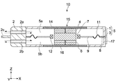
噴流発生装置10は、筐体5、振動アクチュエータ15及びノズル体2を備えている。筐体5は、上カバー1及び下カバー3により構成されている。図2に示すように、上カバー1及び下カバー3のそれぞれの後方であって、カバー1及び3のY方向での両側には、上カバー1及び下カバー3を連結するための連結部材18が装着される装着部1b及び3bが設けられている。また、両カバー1及び3のそれぞれの前方であって、両カバー1及び3のY方向での両側には、ノズル体2が装着されるための突起部1c及び3cが設けられている。ノズル体2の両側面には、その突起部1c及び3cが係合する穴2dがそれぞれ形成されている。
The
なお、連結部材18や、連結部材18が装着される装着部1b、3b等は、必ずしもなくてはならないわけではない。上カバー1と下カバー3とを、例えばネジ、接着剤、圧着、溶着、超音波接合、またはレーザ接合等により接合することができる。あるいはその他の接合方法であってもよい。
Note that the connecting
ノズル体2には、複数の空気の流路2aが上段に1列に設けられ、また、複数の空気の流路2bが下段に1列に設けられている。上下の流路2a及び2bの間には、仕切り板2cが、Y方向に並んだ流路2a(または2b)の数の分だけ設けられている。後述するように、噴流発生装置10が動作するとき、上下の流路2a及び2bにおいて、常に風向きが逆になる。この仕切り板2cが設けられることにより、例えば流路2bから吐出された空気が流路2aから吸い込まれにくくなり、効率良く空気が吐出されるようになる。
In the
仕切り板2cは複数設けられているが、このような形態に限らず1枚の板で構成されていてもよい。しかしながら、図1等に示すように仕切り板2cが複数に分割されていることにより、後述するように、図示しないヒートシンクを構成する各放熱フィンの間に各仕切り板2cを嵌め込むことができる。これにより、噴流発生装置10とヒートシンクとを容易かつ正確に位置決めすることができる。
Although a plurality of
振動アクチュエータ15は、対向して配置された2つのマグネット4及び6、これらのマグネット4及び6の間に配置されたスペーサ7、スペーサ7の周囲に配置されたコイル12、コイル12が装着された振動体(振動板)9、振動板9の周囲に装着され振動板9を支持する弾性支持部材11、マグネット4及び6にそれぞれ接続されたヨーク14及び16を有している。
The
2つのマグネット4及び6は、その対向方向(Z方向)であり、同じ極性同士が向かい合うように、すなわち両マグネット4及び6の磁界が互いに反発するように、それぞれ着磁されている。これにより、両マグネット4及び6は反発磁界を形成する。駆動電流が流れるコイル12は、振動板9のほぼ中央に設けられた穴9aに嵌め込まれるように装着されている。図4は、このように配置されたマグネット4及び6が発生する磁界の様子を示す図である。コイル12は、Z方向にほぼ垂直な方向に流れる反発磁界を受ける位置に配置される。つまり、マグネット4及び6が配列されるZ方向の中央位置dにコイル12が配置され、振動板9もその中央位置dに配置される。この場合、マグネット4及び6が同じ磁束を発生するマグネットであることが望ましい。このような構成によれば、振動板9のZ方向(振動方向)でほぼ完全な対称構造を実現することができる。
The two
弾性支持部材11は、開口されたフレーム8の当該開口に装着され、フレーム8は、上カバー1及び下カバー3に挟まれるように装着される。例えば、フレーム8の角にそれぞれ設けられたネジ穴8aと、上カバーに設けられたネジ穴1a(または、下カバー3に設けられたネジ穴3a)とが対応し、図示しないネジ等により固定される。これにより、振動アクチュエータ15と上カバー1(または下カバー3)とが固定される。
The
なお、そのような形態に限らず、上カバー1の上面1d(または下カバーの下面3d)からネジ穴が貫通し、その上面1d(または下カバーの下面3d)からネジ穴1a、8a3aを介してネジ止めされるような形態であってもよい。この場合、振動アクチュエータ15、上カバー1及び下カバー3が一度に固定される。また、この場合は連結部材18は必要ない。
In addition, the screw hole penetrates from the
磁性材料でなるヨーク14及び16は、例えば円板状をなし、マグネット4及び6のX−Y平面内での幅より大きい幅を有する。円板状に限られず、平板状であればどのような形であってもよい。ヨーク14は、上カバー1の一部を構成している。具体的には、上カバー1が開口され、その開口部にヨーク14が装着されている。ヨーク16についても同様に、下カバー3の一部を構成している。ヨーク14及び16が設けられることにより、筐体5の外側への漏れ磁束を効果的に抑制することができる。図5は、ヨーク14及び16が設けられる場合の磁界の様子を示す図である。この図から、漏れ磁界がほとんどないことが分かる。また、ヨーク14及び16が、平板状でなるため振動アクチュエータ15の厚さが薄くなり、さらにヨーク14及び16が筐体5の一部を構成するので、噴流発生装置10の薄型化を実現することができる。
The
なお、ヨーク14及び16は必ずしも必要ない。あるいは、ヨーク14及び16がない場合に、上カバー1及び下カバー3のうち少なくとも一方が磁性材料で、磁気遮蔽の機能を有していてもよい。
The
筐体5の内部は、振動板9、弾性支持部材11及びフレーム8によって二分され、チャンバ5a及び5bが形成される。上部に形成されたチャンバ5aは、上記流路2aを介して筐体5の外部と連通し、下部に形成されたチャンバ5bは、上記流路2bを介して筐体5の外部と連通している。
The inside of the
なお、本実施の形態では、筐体5とノズル体2とが別体であるが、一体であってもよい。あるいは、ノズル体2がなく、ノズル体2の流路2a及び2bの代わりとして、筐体5に複数の開口が形成されていてもよい。言い換えると、「流路2a」及び「流路2b」は、「開口」の概念に含まれる。
In the present embodiment, the
図3に示すように、筐体5の後方の側面には、振動アクチュエータ15を駆動するための駆動回路基板17が配置されている。駆動回路基板17には、例えば駆動用のIC等が搭載され、駆動回路基板17から図示しない導線が引き出され、コイル12に接続されている。しかし、このように駆動回路基板17の代わりに、上記導線(コイル12から延びる導線)に電気的に接続された端子が単に設けられる構成であってもよい。
As shown in FIG. 3, a
振動板9は、例えば樹脂、紙、または金属でなる。特に、振動板9が紙でなることにより、非常に軽量化される。紙は、樹脂ほど任意な形状に作製しにくいが、軽量化では有利である。振動板9が樹脂の場合、成形により任意の形状に作製しやすい。一方、振動板9が金属の場合、例えば銅、アルミニウム、あるいはステンレス等でなる。あるいはマグネシウムでもよい。マグネシウムは軽量で射出成形が可能であるので有利となる。振動板9は平板状でなくてもよく、例えば立体的な振動体であってもよい。振動板9の平面形状(X−Y平面内での形状)は、円、楕円、矩形、あるいはこれらの組み合わせ等の形状が考えられる。
The
筐体5は、例えば、樹脂、ゴム、または金属でなる。樹脂やゴムは成形で作製しやすく量産向きである。また、筐体5が樹脂やゴムの場合、振動アクチュエータ15の駆動により発生する音、あるいは振動板9が振動することにより発生する空気の気流音等を抑制することができる。つまり、筐体5が樹脂やゴムの場合、それらの音の減衰率も高くなり、騒音を抑制することができ、さらに、軽量化に対応でき、低コストとなる。樹脂等の射出成形で筐体5が作製される場合は、上述したようにノズル体2と一体で成形することが可能である。しかし、図2に示すように、筐体5とノズル体2とは別体の方が、噴流発生装置10の作製が容易になる。筐体5が熱伝導性の高い材料、例えば金属でなる場合、振動アクチュエータ15から発せられる熱を筐体5に逃がして筐体5の外部に放熱することができる。金属としては、アルミニウムや銅が挙げられる。熱伝導性を考慮する場合、金属に限らず、カーボンであってもよい。金属としては、射出成形が可能なマグネシウム等も用いることができる。さらに、高温での使用や、特殊用途ではセラミックスの筐体であってもよい。ヨーク14及び16がない場合、筐体5は、上述したように、磁性材料とすることも可能である。
The
弾性支持部材11は、ゴム等でなるが、伸縮性のある材料であれば何でもよく樹脂でもよい。弾性支持部材11の形状は、振動板9の形状(外形)による。図3のように弾性支持部材11の断面形状は、1つの山部及び1つの谷部を有するものが用いられる。以下、これを2ロールタイプの弾性支持部材という。1つの谷部のみ、または1つの山部のみからなる弾性支持部材の場合、図3中の上下方向の高さが高くなり、厚さが増えてしまう。山部及び谷部がそれぞれ複数ある場合、振動板9が振動するときに振動方向(Z方向)以外の複雑な動きが発生するおそれがあり、効率が落ちる可能性がある。また、それによって騒音が大きくなるおそれもある。したがって、2ロールタイプの弾性支持部材が用いられることが望ましい。しかしながら、必ずしも2ロールタイプが用いられなければならないわけではない。
The
スペーサ7が、例えば磁性材料でなる場合、コイル12が配置される領域の磁束密度を増やすことができ、振動板9を効率良く振動させることができるので、消費電力を抑えることができる。しかし、スペーサ7は非磁性材料でもよい。非磁性材料として、例えば、樹脂、アルミニウム、銅、ゴム等が挙げられるが、これら以外の非磁性材料であってもよい。極論にはスペーサ7はなくてもよい。
When the
スペーサ7、マグネット4及び6の形状は円筒形状としたが、これに限られず、例えば、角柱形状としてもよい。あるいは、スペーサ7、マグネット4及び6の平面形状(X−Y平面内での形状)は、すべて同じ形状であることが望ましいが、必ずしもそうでなくてもよく、ばらばらでもよい。
The shape of the
以上のように構成された噴流発生装置10の動作について説明する。
The operation of the jet
コイル12に例えばサイン波の交流電圧が印加されると、振動板9は正弦波振動を行う。これにより、チャンバ5a及び5b内の容積が増減する。チャンバ5a及び5bの容積変化に伴い、それらチャンバ5a及び5bの圧力が交互に増減し、これに伴い、空気がそれぞれ流路2a及び2bを介して交互に脈流として吐出される。流路2a及び2bから空気が吐出されるときに筐体5やノズル体2の周囲の気圧が低下することにより、当該周囲の空気が流路2a及び2bから吐出される空気に巻き込まれ、合成噴流が発生する。この合成噴流が、図示しない発熱体や高熱部に吹き付けられることにより、当該発熱体を冷却することができる。なお、発熱体としては、例えばIC、コイル、抵抗等の電子部品、あるいは放熱フィン(ヒートシンク)等が挙げられるが、これらに限られず発熱するものなら何でもよい。
For example, when a sinusoidal AC voltage is applied to the
一方、流路2a及び2bから空気が吐出されるときに、各流路2a及び2bから独立して、特に気流音による騒音が発生する。しかしながら、各流路2a及び2bで発生する各音波は逆位相の音波であるため互いに弱められる。これにより、ある程度騒音が抑制され、静音化を図ることができる。特に、流路2a及び2bの開口面積(気流の方向にほぼ垂直な面、つまり流路断面積)やそれらの数を同じにすることで、Z方向での対称性が向上し、より騒音が低減する。
On the other hand, when air is discharged from the
本実施の形態では、マグネット4及び6による反発磁界が形成されて、Z方向に十分な幅のある磁束が形成されるので、コイルのZ方向の長さが短くてもコイル12は十分な反発磁界による磁束を受ける。すなわち、振動アクチュエータ15のZ方向での厚さ、あるいは噴流発生装置10の厚さを薄くすることができる。
In the present embodiment, a repulsive magnetic field is formed by the
さらに、本実施の形態に係る振動アクチュエータ15は、スペーサ7を挟んでマグネット4及び6が対向して配置された構造を有するので、図4または図5で示したような対称的な磁界が形成される。したがって、コイル12に発生する力は振幅中心から両死点でほぼ同じになり、振幅中心からの振動の対称性が高くなる。振動の対称性とは、例えば振幅(変位)の対称性、あるいはコイル12に発生する力等の対称性である。
Further, since the
また、本実施の形態では、対称性が向上することにより振動の線形性が高くなるので、例えばコイル12を駆動する駆動電流(入力電流)に対する変位応答に高調波成分が重畳しにくく、きれいに振動板9を振動させることができる。その結果、例えば、チャンバ5a及び5bの形状や容積、それらチャンバ5a及び5b内の気流の対称性が向上し、騒音が抑制される。
In the present embodiment, since the linearity of the vibration is improved by improving the symmetry, for example, the harmonic component is difficult to be superimposed on the displacement response to the drive current (input current) for driving the
本実施の形態では、従来のように磁気ギャップの中をコイルが動くような構成ではないので、コイル12を横方向(X−Y平面内)で厚く巻くことが可能である。すなわち、コイル12の層が厚くなり、力F=iBLにおける長さLを稼ぐことが可能となるため、同じ電流でもより強い力を発生することが可能となる。ただし、あまりコイル12の層が厚い場合、コイル12の重量が増えるので、振動板9が振動するときのエネルギーロスとなる。また、同時にインピーダンスの増加を招きエネルギーロスとなる。したがって、コイル12の厚さは最適値を見つけることができれば、振動板9が効率良く駆動され、低い消費電力で高い冷却性能を得ることができる。
In the present embodiment, since the coil does not move in the magnetic gap as in the prior art, the
図6は、コイル12の上下変位を横軸とし、コイル12に一定の電流を流したときに発生するローレンツ力を縦軸としたグラフを示す。また、参考のため従来構造(例えば、特許文献1の図49等のボイスコイルモータ)の変位と力のグラフを図7に示す。なお、力の単位は、図6に示す例では、40AT(アンペアターン)での力を示し、図7に示す例では、10AT(アンペアターン)での力を示している。
FIG. 6 is a graph in which the vertical displacement of the
図6に示す例では、±1.5mmの振幅を目標に設計されている。このストローク内での力の変化量は、(0.38−0.28)/0.38=26%程度に収まっている。一方、図7に示す従来構造の例では、±2mmの振幅を目標に設計されている。このストローク内での力の変化量は、(0.28−0.06)/0.28=78%程度もの力の変化を発生している。すなわち、これらのグラフから、本実施の形態に係る振動アクチュエータ15は、薄い構造であるにもかかわらず、またコイル12の上下変位にかかわらず、コイル12に発生する力の変化量が、従来に比べ十分に少ないことが分かる。このことにより、上述したように、本実施の形態では、振動の線形性が高く、入力する電流波形に対する変位応答に高調波成分が重畳しにくく、きれいな応答になる。
The example shown in FIG. 6 is designed with an aim of an amplitude of ± 1.5 mm. The amount of change in force within the stroke is within the range of (0.38−0.28) /0.38=26%. On the other hand, the example of the conventional structure shown in FIG. 7 is designed with an aim of an amplitude of ± 2 mm. The amount of change in force within this stroke generates a change in force of about (0.28−0.06) /0.28=78%. That is, from these graphs, although the
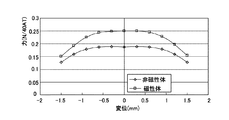
図8は、図6及び図7と同様に、コイルの変位とローレンツ力との関係を示すグラフであり、スペーサ7の材質が磁性体と非磁性体の場合を比較した例を示す。この2種類の材質でなるスペーサが設けられる振動アクチュエータにおいて、コイルに同一電流を流している。このグラフから分かるように、同一電流でも30%程度、発生する力を増加させることが可能となり、同じ力を発生するのに小さな電流でよい。すなわち、消費電力を抑えることが可能となる。
FIG. 8 is a graph showing the relationship between the coil displacement and the Lorentz force, similar to FIGS. 6 and 7, and shows an example in which the
図9は、図3に示すヨーク14及び16が設けられた振動アクチュエータ15のコイルの変位と力のグラフである。このグラフから分かるように、ヨーク14及び16が設けられる例では、非磁性体のスペーサが設けられる例に比べて、約50%以上のローレンツ力の増加が得られた。また、磁性体のスペーサ7が設けられる例に比べて、約2倍以上のローレンツ力の増加が得られた。この場合、消費電力として約半分にすることが可能となる。
FIG. 9 is a graph of the displacement and force of the coil of the
(第2実施形態)
次に、本発明の第2の実施の形態について説明する。図10は、本実施の形態に係る噴流発生装置を示す分解斜視図である。図11は、図10に示す噴流発生装置の断面図である。これ以降の説明では、図1等に示した実施の形態に係る噴流発生装置10の部材や機能等について同様のものは説明を簡略または省略し、異なる点を中心に説明する。
(Second Embodiment)
Next, a second embodiment of the present invention will be described. FIG. 10 is an exploded perspective view showing the jet flow generating device according to the present embodiment. FIG. 11 is a cross-sectional view of the jet flow generating device shown in FIG. In the following description, the same members, functions, and the like of the jet
噴流発生装置20が備える振動アクチュエータ35は、中央のマグネット24、マグネット24に対向してそれぞれZ方向の両側に配置されたマグネット4及び6、マグネット24とマグネット4との間に配置されたスペーサ7a、マグネット24とマグネット6との間に配置されたスペーサ7bを有している。また、振動アクチュエータ35は、各スペーサ7a及び7bの周囲に配置された2つの振動板9を有している。振動板9、コイル12、弾性支持部材11及びフレーム8は、図1〜図3に示した振動アクチュエータ15が有する振動板9、コイル12、弾性支持部材11及びフレーム8と同様の構成でなる。
The
図10に示すように、筐体フレーム13は床板または天井板等を有していない。上側の振動板9等は、上カバー1と筐体フレーム13との間に配置されている。下側の振動板9等は、下カバー3と筐体フレーム13との間に配置されている。各振動板9、9等によって、筐体25(図11参照)内が仕切られ、これにより中央チャンバ25a、上部チャンバ25b、下部チャンバ25cの3つのチャンバが形成される。
As shown in FIG. 10, the
図12に示すように、上部のマグネット4の厚さfは、下部のマグネット6の厚さhとほぼ同じである。中央のマグネット24の厚さgは、fやhのほぼ2倍となっている。あるいは、中央のマグネット24は、マグネット4または6と同じマグネットが2つ重ねられて構成されている。つまり、中央のマグネット24は、マグネット4または6とほぼ同じ磁束密度のマグネットが2つ設けられて構成されてもよい。これにより、マグネット24を中心として、Z方向に磁界が対称的に形成されるので、各振動板9の振幅中心からの振動の対称性が高くなる。
As shown in FIG. 12, the thickness f of the
ノズル体22は、チャンバ25aと筐体25の外部とを連通する流路22a、チャンバ25bと筐体25の外部とを連通する流路22b、チャンバ25cと筐体25の外部とを連通する流路22cを有する。仕切り板22dは、流路22aと流路22bを仕切り、し基板22eは、流路22aと流路22cを仕切る。各流路22a、22b及び22cの開口面積、すなわち、Z−Y平面内での各流路の断面積は、すべてほぼ同じに設計されている。各流路の開口面積がすべて同じになることで、すべての流路でほぼ同じ周波数で音波が発生する。
The
また、中央のチャンバ25aの容積は、上部のチャンバ25bの容積のほぼ2倍になっている。これは、筐体フレーム13のZ方向の厚さが、上カバー1のZ方向の厚さのほぼ2倍に設計されればよい。また、上部のチャンバ25bと下部のチャンバ25cとはほぼ同じ容積になっている。中央のチャンバ25aの容積が、チャンバ25bの容積またはチャンバ25cの容積の2倍になっている分、流路22aの数も、流路22bの数または流路22cの数の2倍にされている。つまり、流路22aは、流路22bの数と流路22cの数とを足した数だけ設けられている。
The volume of the
次に、以上のように構成された噴流発生装置20の動作について説明する。例えば振動板9同士が互いに近づくように、かつ、互いに遠ざかるように同期して振動するように、各コイル12に電圧が印加される。各振動板9が互いに近づくと、中央のチャンバ25aの容積が小さくなり、流路22aを介して空気が吐出される。各振動板9が互いに遠ざかると、上部のチャンバ25b及び下部のチャンバ25cのそれぞれの容積が同じタイミングで小さくなり、流路22b及び22cを介して空気が吐出される。
Next, the operation of the jet
本実施の形態によれば、振動板9が2つ設けられているので、振動アクチュエータ35の厚さは増えるが、空気の吐出量を増やすことができる。また、振動板9同士が互いに近づくように、かつ、互いに遠ざかるように同期して振動するので、全体の振動がキャンセルされ、噴流発生装置20の全体の振動がなくなる。
According to the present embodiment, since two
また、本実施の形態では、中央のマグネット24が、マグネット4(または6)が2つ分で構成されるので、上記したように、磁束密度がマグネット24を中心として対称的になり、振動の対称性が向上する。このような対称構造に加えてヨーク14及び16が設けられることにより、外部への漏れ磁束を最小に抑えることができる。
In the present embodiment, since the
本実施の形態では、中央のチャンバ25aから吐出される空気の量と、各チャンバ25b及び25cから吐出される空気量の合計とがほぼ同じになる。すなわち、上述したようにすべての流路25a、25b及び25cから発生する音波の周波数がほぼ同じで、中央のチャンバ25aから吐出される空気量と、チャンバ25b及び25cから吐出される空気量の合計とがほぼ同じであれば、きれいに音波が相殺され騒音が低減される。
In the present embodiment, the amount of air discharged from the
図13は、上記各図に示した噴流発生装置10(または20等)が電子機器としてPC50に搭載された状態を示す斜視図である。噴流発生装置10から供給される合成噴流が発熱体としてのヒートシンク46に吹き付けられ、ヒートシンク46の背後に設けられたPC筐体の排気口51から、熱を持つ空気が排出される。
FIG. 13 is a perspective view showing a state in which the jet flow generating device 10 (or 20 or the like) shown in the above drawings is mounted on the
本発明は以上説明した実施の形態には限定されるものではなく、種々の変形が可能である。 The present invention is not limited to the embodiment described above, and various modifications are possible.
上記第1の実施の形態において、マグネット4及び6の幅(外径)を、コイル12のX−Y平面における幅よりも大きく形成して、かつ、リング状に形成してもよい。また、上記第2の実施の形態において、マグネット4、6及び24の幅(外径)を、両コイルのX−Y平面における幅よりも大きく形成して、かつ、リング状に形成してもよい。これにより、両コイル12周辺の磁場を強くすることで、消費電力を抑えることができる。
In the first embodiment, the widths (outer diameters) of the
上記各実施の形態に係る噴流発生装置10、20は、空気を吐出する形態を例に挙げた。しかし、空気に限らず、窒素、ヘリウムガス、あるいはアルゴンガス、その他の気体であってもよい。
The
図13において、電子機器としてラップトップ型のPCを例に挙げたが、デスクトップ型のPCでもよい。PCに限らず、PDA(Personal Digital Assistance)、電子辞書、カメラ、ディスプレイ装置、オーディオ/ビジュアル機器、プロジェクタ、携帯電話、ゲーム機器、カーナビゲーション機器、ロボット機器、その他の電化製品等が挙げられる。 In FIG. 13, a laptop PC is taken as an example of the electronic device, but a desktop PC may be used. Not only a PC but also a PDA (Personal Digital Assistance), an electronic dictionary, a camera, a display device, an audio / visual device, a projector, a mobile phone, a game device, a car navigation device, a robot device, and other electrical appliances.
(第3実施形態)
次に、本発明の第3の実施形態について説明する。なお、本実施形態以降の実施形態において、上記図3等で示した噴流発生装置10と同様の構成または機能となる部分については同一の符号を付し、説明を省略または簡略化し、異なる点を中心に説明する。
(Third embodiment)
Next, a third embodiment of the present invention will be described. In addition, in embodiment after this embodiment, the same code | symbol is attached | subjected about the part which becomes the structure or function similar to the
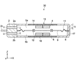
図14は、本実施の形態における噴流発生装置を示す断面図である。上述したように、上記第1の実施形態における噴流発生装置10においては、スペーサ7はなくても構わない。同図に示すように、本実施形態の噴流発生装置30においては、スペーサ7をなくし、また振動板9は、上記穴9aの無い完全な平面状としている。この場合コイル12は、当該振動板9に例えば埋め込まれるように装着されているが、振動板9の表面または裏面に貼付されるように装着されていてもよい。
FIG. 14 is a cross-sectional view showing the jet flow generating device in the present embodiment. As described above, in the jet
この構成により、チャンバ5aとチャンバ5bとの間は完全に密閉されることとなるため、各チャンバ間における気体漏れを防いで、ノズル体2を介して効率よく気体を吐出することができる。これにより消費電力も抑えることが可能となる。また、この噴流発生装置30は、密閉性を向上させたことで、気体のみならず液体を吐出するためにも用いることができる。
With this configuration, the
(第4実施形態)
次に、本発明の第4の実施形態について説明する。上述したように、上記第3の実施形態の噴流発生装置30によれば、密閉性を高めることで、気体のみならず液体を効率よく吐出することも可能である。本実施形態においては、上記噴流発生装置を、流体として気体及び液体を輸送可能なポンプ装置として用いることとしている。
(Fourth embodiment)
Next, a fourth embodiment of the present invention will be described. As described above, according to the jet
図15は、本実施形態における噴流発生装置40を示す断面図である。なお、本実施形態以降の実施形態において上記第3実施形態における噴流発生装置30と同様の構成及び機能となる部分については同一の符号を付し、説明を省略または簡略化し、異なる点を中心に説明する。
FIG. 15 is a cross-sectional view showing the jet
同図に示すように、噴流発生装置40においては、上記各実施形態におけるノズル体を廃し、また筐体5の前方の側面には、上記各実施形態において気体の吐出及び吸入を行っていた上下の流路2a及び2bの代わりに、もっぱら流体の吐出を行うための吐出口41a及び41bを設けている。また、筐体5の後方の側面には、各吐出口41a及び41bに対向するように、もっぱら流体の吸入を行うための吸入口42a及び42bを設けている。
As shown in the figure, in the jet
また各吐出口41a及び41bと、各吸入口42a及び42bには、各吐出口及び各吸入口からの逆流を防ぐための逆止弁43a及び43bと、逆止弁44a及び44bとが設けられている。
The
すなわち、本実施形態においては、流体の吸入と吐出とを各吸入口と各吐出口とで別個に行い、噴流発生装置40の背面方向から吸入した流体を前面方向から吐出することで流体の輸送を行うことが可能となっている。
That is, in the present embodiment, the fluid is sucked and discharged separately at each suction port and each discharge port, and the fluid sucked from the back surface direction of the jet
具体的には、振動板9が同図Z方向の下方向へ駆動した場合には、チャンバ5a内の気圧が下がり、チャンバ5b内の気圧が上がることで、吸入口42aを介してチャンバ5a内に流体が吸入される。またこのとき、チャンバ5b内の流体は吐出口41bを介して筐体外へ吐出される。
Specifically, when the
逆に、振動板9が同図Z方向の上方向へ駆動した場合には、チャンバ5a内の気圧が上がり、チャンバ5b内の気圧が下がることで、吸入口42bを介してチャンバ5b内に流体が吸入され、また上述のようにしてチャンバ5a内に吸入された流体が吐出口41aを介して筐体外へ吐出される。
On the other hand, when the
なお、同図においては、上記駆動回路基板17は図示されていないが、本実施形態において駆動回路基板17は例えば噴流発生装置40の、図15において表れない側面に設けられる。
In addition, although the said drive circuit board |
以上のように、本実施形態によれば、振動板9によりチャンバ5aとチャンバ5bとの間を密閉して各チャンバ間の流体漏れを防ぎ、また吐出口と吸入口とを別個に設けることで、気体のみならず液体も効率よく圧送することが可能となり、例えば人工心臓のように細やかで複雑な拍動も可能となる。
As described above, according to the present embodiment, the
(第5実施形態)
次に、本発明の第5の実施形態について説明する。図16は、本実施形態における噴流発生装置60を示す断面図である。
(Fifth embodiment)
Next, a fifth embodiment of the present invention will be described. FIG. 16 is a cross-sectional view showing the jet
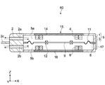
上記第3及び第4の実施形態においては、各マグネット4及び6を円板状に構成していたが、同図に示すように、本実施形態においては、各マグネット4及び6をリング状に形成している。これにより、同図X−Y平面においてコイル12の外側にマグネット4及び6が配置されることとなるため、コイル12周辺の磁場を強くすることができ、振動板9をより効率良く振動させることができる。したがって、噴流発生装置60の消費電力を抑えることができる。
In the third and fourth embodiments, the
(第6実施形態)
次に、本発明の第6の実施形態について説明する。図17は、本実施形態における噴流発生装置70を示す断面図である。
(Sixth embodiment)
Next, a sixth embodiment of the present invention will be described. FIG. 17 is a cross-sectional view showing the jet
同図に示すように、本実施形態の噴流発生装置70においては、上記第3〜5の実施形態に比べて、コイル12の同図X−Y平面における幅を厚くして平面状に形成している。なお、本実施形態においては、コイル12は中空に形成しているが、中空でない完全な平板状に形成しても構わない。
As shown in the figure, in the jet
図18は、コイルの変位とローレンツ力との関係を示すグラフであり、コイル12を平面状に形成した場合と非平面状に形成した場合とを比較シミュレーションした例を示している。なお、この比較において、コイル12には同一電流を流している。同図に示すように、コイル12を平面状に形成することで、平面状に形成しない場合に比べて、発生する力が約7%〜8%増加することが分かる。
FIG. 18 is a graph showing the relationship between the coil displacement and the Lorentz force, and shows an example in which a comparison simulation is performed between the case where the
上記第3〜5の実施形態においては、マグネット4とマグネット6との間にヨーク(磁性体のスペーサ)を設けていないため、コイル12近傍の磁場が小さくなり、消費電力が増加してしまう可能性がある。しかし、本実施形態のように、コイル12の同図X−Y方向への巻き数を多くして平面状に形成することで、力F=iBLにおける長さLを稼ぐことができるため、ヨークを設けなくともコイル12を効率よく駆動させ、消費電力を低減することが可能となる。また、Z方向におけるコイル12の幅を薄くすることで、コイル12が重くなり、振動板9の駆動に影響をきたすことも防ぐことができる。
In the third to fifth embodiments, since the yoke (magnetic spacer) is not provided between the
(第7実施形態)
次に、本発明の第7の実施形態について説明する。図19は、本実施形態における噴流発生装置80を示す断面図である。
(Seventh embodiment)
Next, a seventh embodiment of the present invention will be described. FIG. 19 is a cross-sectional view showing a jet
上記第3〜第6の実施形態においては、マグネット4とマグネット6との間にヨークを設けていなかったが、本実施形態においては、同図に示すように、マグネット4とマグネット6との間に挟まれるように、振動板9に平板状(例えば円板状の)ヨーク19を設けている。当該ヨークは高透磁率の材料からなり、振動板9の駆動とともに同図Z方向へ移動可能となっている。当該ヨーク19は、コイル12と同様、例えば振動板9に埋め込まれるように装着されるが、振動板9の表面または裏面、または両面に貼付されるように装着されてもよい。
In the third to sixth embodiments, no yoke is provided between the
図20は、本実施形態におけるマグネット4及び6が発生する磁界の様子を示す図であり、コイル12が両マグネットのほぼ中間に位置している場合(同図(a)及び(b))と、マグネット4側へ移動した場合(同図(c)及び(d))とで、それぞれ上記第3実施形態にようにヨーク19を設けない場合(同図(a)及び(c))と本実施形態のようにヨーク19を設けた場合(同図(b)及び(d))の磁界の様子を比較シミュレーションした例を示している。
FIG. 20 is a diagram showing the state of the magnetic field generated by the
また、図21は、コイルの変位とローレンツ力との関係を示すグラフであり、振動板9にヨーク19を設けた場合と設けない場合とを比較シミュレーションした例を示している。
FIG. 21 is a graph showing the relationship between the coil displacement and the Lorentz force, and shows an example in which a comparison simulation is performed between the case where the
図20に示すように、振動板9にヨーク19を設けることで、マグネット4及び6が形成する反発磁界における漏れ磁界がほぼなくなり、コイル12に鎖交する磁束を増やすことが可能となる。これにより、図21に示すように、発生する力も最大約30%程度増加させることができることが分かる。
As shown in FIG. 20, by providing the
すなわち、本実施形態によれば、チャンバ5aとチャンバ5bとの間の密閉性を保ったまま、コイル12へ鎖交する磁束を増やすことができ、消費電力を抑えることができる。
That is, according to the present embodiment, it is possible to increase the magnetic flux interlinking with the
なお、上記第3、第5〜第7の実施形態において示したリング状のマグネット4及び6、平面状のコイル12、ヨーク19を任意に組み合わせて噴流発生装置を構成してもよい。またそれらを用いて第4の実施形態において示したポンプ装置を構成しても構わない。
The jet generator may be configured by arbitrarily combining the ring-shaped
(第8実施形態)
次に、本発明の第8の実施形態について説明する。図22は、本実施形態における噴流発生装置90を示す断面図である。なお、本実施形態以降の実施形態において、上記第2の実施形態の噴流発生装置20と同様の構成及び機能となる部分については同一の符号を付し、説明を省略または簡略化する。
(Eighth embodiment)
Next, an eighth embodiment of the present invention will be described. FIG. 22 is a cross-sectional view showing the jet
同図に示すように、本実施形態の噴流発生装置90においては、上記第2の実施形態の噴流発生装置20のように振動板9を2つ(チャンバを3つ)設けた構成において、中央のマグネット24を廃し、また各マグネット4、24及び6に挟まれた2つのスペーサ7a及び7bも廃している。また2つの振動板9の各穴9aを廃して、各振動板9が中央のチャンバ25aと上部のチャンバ25bとの間、及びチャンバ25aと下部のチャンバ25cとの間を完全に密閉するようにしている。また各コイル12は、各振動板9に例えば埋め込まれるように装着されているが、各振動板9の表面または裏面に貼付されるように装着されていてもよい。
As shown in the drawing, in the jet
すなわち、本実施形態の噴流発生装置90においては、2つの振動板(3つのチャンバ)を設けた構成において、上記図14で示した第3の実施形態の噴流発生装置30と同様の効果を得られるように構成している。したがって、本実施の形態によれば、上記第3の実施形態の噴流発生装置30に比べて、空気の吐出量を増やし、噴流発生装置90の全体の振動をキャンセルすることができるとともに、各チャンバ間の密閉性を保つことで、液体及び気体を含む流体を効率よく吐出することが可能となる。
That is, in the jet
(第9実施形態)
次に、本発明の第9の実施形態について説明する。図23は、本実施形態における噴流発生装置100を示す断面図である。なお、本実施形態以降の実施形態において上記第8実施形態の噴流発生装置90と同様の構成及び機能となる部分については同一の符号を付し、説明を省略または簡略化し、異なる点を中心に説明する。
(Ninth embodiment)
Next, a ninth embodiment of the present invention will be described. FIG. 23 is a cross-sectional view showing the jet
同図に示すように、本実施形態の噴流発生装置100においては、上記図15で示したポンプ装置としての噴流発生装置40を、2つの振動板(3つのチャンバ)を設けた構成において実現している。すなわち、筐体25に各3つの吸入口102a〜102c及び吐出口101a〜101cを設けて、各吸入口102a〜102cには逆止弁104a〜104cを、各吐出口101a〜101cには逆止弁103a〜103cを設けている。また、各チャンバ25a〜25cは、各振動板9により密閉されている。
As shown in the figure, in the jet
各振動板9は、上記第2実施形態と同様に、互いに近づくように、また互いに遠ざかるように同期して駆動する。したがって、各振動板9が互いに近づくように駆動した場合には、チャンバ25aの気圧が上がり、チャンバ25b及び25cの気圧が下がることで、チャンバ25b及び25cから吸入口102b及び102cを介して流体が吸入され、またチャンバ25a内の流体が吐出口101aを介して筐体外へ吐出される。
Each
また逆に、各振動板9が互いに遠ざかるように駆動した場合には、チャンバ25a内の気圧が下がり、チャンバ25b及び25c内の気圧が上がることで、吸入口102aからチャンバ25a内に流体が吸入され、また上述のようにしてチャンバ25b及び25c内に吸入された流体が吐出口101b及び101cを介して筐体外へ吐出される。
Conversely, when the
以上により、本実施形態によれば、上記第4実施形態の噴流発生装置40に比べて吐出量を増加させ、また振動を低減することができるとともに、上記第8の実施形態の噴流発生装置90に比べて、気体のみならず液体も効率よく圧送することが可能となる。
As described above, according to the present embodiment, the discharge amount can be increased and vibration can be reduced as compared with the jet
(第10実施形態)
次に、本発明の第10の実施形態について説明する。図24は、本実施形態における噴流発生装置110を示す断面図である。
(10th Embodiment)
Next, a tenth embodiment of the present invention will be described. FIG. 24 is a cross-sectional view showing the jet
同図に示すように、本実施形態の噴流発生装置110においては、上記第5の実施形態において図16で示したリング状のマグネット4及び6を、2つの振動板(3つのチャンバ)を設けた構成において実現している。
As shown in the figure, in the
したがって、この構成によれば、上記第5の実施形態の噴流発生装置60に比べて吐出量を増加させ、また振動を低減することができるとともに、上記第8の実施形態の噴流発生装置90に比べて、コイル12周辺の磁場を強くして振動板9をより効率良く振動させ、噴流発生装置110の消費電力を抑えることができる。
Therefore, according to this configuration, the discharge amount can be increased and vibration can be reduced as compared with the jet
(第11実施形態)
次に、本発明の第11の実施形態について説明する。図25は、本実施形態における噴流発生装置120を示す断面図である。
(Eleventh embodiment)
Next, an eleventh embodiment of the present invention will be described. FIG. 25 is a cross-sectional view showing the jet
同図に示すように、本実施形態の噴流発生装置120においては、上記第6の実施形態において図17で示した平面状のコイル12を、2つの振動板(3つのチャンバ)を設けた構成において実現している。
As shown in the figure, in the
したがって、この構成によれば、上記第6の実施形態の噴流発生装置70に比べて吐出量を増加させ、また振動を低減することができるとともに、上記第8の実施形態の噴流発生装置90に比べて、力F=iBLにおける長さLを稼ぐことができるため、ヨークを設けなくともコイル12を効率よく駆動させ、消費電力を低減することが可能となる。
Therefore, according to this configuration, the discharge amount can be increased and vibration can be reduced as compared with the jet
(第12実施形態)
次に、本発明の第12の実施形態について説明する。図26は、本実施形態における噴流発生装置130を示す断面図である。
(Twelfth embodiment)
Next, a twelfth embodiment of the present invention will be described. FIG. 26 is a cross-sectional view showing the jet
同図に示すように、本実施形態の噴流発生装置130においては、上記第7の実施形態において図19に示したヨーク19を、2つの振動板(3つのチャンバ)を設けた構成において実現している。
As shown in the figure, in the jet
したがって、この構成によれば、上記第7の実施形態の噴流発生装置80に比べて吐出量を増加させ、また振動を低減することができるとともに、上記第8の実施形態の噴流発生装置90に比べてコイル12へ鎖交する磁束を増やすことができ、消費電力を抑えることができる。
Therefore, according to this configuration, the discharge amount can be increased and the vibration can be reduced as compared with the jet
なお、上記第8、第10〜第12の実施形態において示したリング状のマグネット4及び6、平面状のコイル12、ヨーク19を任意に組み合わせて噴流発生装置を構成してもよい。またそれらを用いて第9の実施形態において示したポンプ装置を構成しても構わない。
The jet generator may be configured by arbitrarily combining the ring-shaped
また、上記第3〜第12の実施形態で示した各噴流発生装置を、上記図13に示したようなPC等の電子機器へ搭載することももちろん可能である。 Further, it is of course possible to mount each of the jet flow generating devices shown in the third to twelfth embodiments in an electronic device such as a PC as shown in FIG.
2、22…ノズル体
2a、2b、22a、22b、22c…流路(開口)
4、6、24…マグネット
5、25…筐体
5a、5b、25a、25b、25c…チャンバ
7、7a、7b…スペーサ
9…振動体(振動板)
10、20、30、40、60、70、80、90、100、110、120、130…噴流発生装置
14、16…ヨーク
15、35…振動アクチュエータ
19…ヨーク
46…ヒートシンク
41a、41b、101a〜101c…吐出口
42a、42b、102a〜102c…吸入口
43a、44a、103a〜103c、104a〜104c…逆止弁
50…PC
2, 22 ...
4, 6, 24 ...
10, 20, 30, 40, 60, 70, 80, 90, 100, 110, 120, 130 ...
Claims (36)
第1のマグネットと、
第1の反発磁界を形成するように前記第1のマグネットに対向して配置された第2のマグネットと、
振動することで前記気体の脈流を生成する第1の振動体と、
前記第1の振動体に装着され、前記第1の反発磁界を受けるように配置された第1のコイルと
を具備することを特徴とする振動アクチュエータ。 A vibration actuator for generating a pulsating flow of gas used in a jet generating device for generating a synthetic jet,
A first magnet;
A second magnet disposed opposite the first magnet to form a first repulsive magnetic field;
A first vibrating body that generates a pulsating flow of the gas by vibrating;
A vibration actuator comprising: a first coil mounted on the first vibrating body and arranged to receive the first repulsive magnetic field.
前記第1及び第2のマグネットの間に配置され、磁性材料でなるスペーサをさらに具備することを特徴とする振動アクチュエータ。 The vibration actuator according to claim 1,
A vibration actuator, further comprising a spacer made of a magnetic material, disposed between the first and second magnets.
振動することで前記気体の脈流を生成する第2の振動体と、
第2の反発磁界を形成するように、前記第2のマグネットとの間に前記第1のマグネットを挟んで前記第2のマグネットと対向して配置された第3のマグネットと、
前記第2の振動体に装着され、前記第2の反発磁界を受けるように配置された第2のコイルと
をさらに具備することを特徴とする振動アクチュエータ。 The vibration actuator according to claim 1,
A second vibrating body that generates a pulsating flow of the gas by vibrating;
A third magnet disposed opposite to the second magnet with the first magnet sandwiched between the second magnet so as to form a second repulsive magnetic field;
A vibration actuator, further comprising: a second coil mounted on the second vibrating body and arranged to receive the second repulsive magnetic field.
前記第1及び第3のマグネットの間に配置され、磁性材料でなるスペーサをさらに具備することを特徴とする振動アクチュエータ。 The vibration actuator according to claim 3,
A vibration actuator further comprising a spacer made of a magnetic material and disposed between the first and third magnets.
前記第3のマグネットは、前記第1または第2のマグネットとほぼ同じ磁束密度で磁界を発生する2つのマグネットでなることを特徴とする振動アクチュエータ。 The vibration actuator according to claim 3,
The vibration actuator according to claim 3, wherein the third magnet includes two magnets that generate a magnetic field with substantially the same magnetic flux density as the first or second magnet.
前記第1及び第2のマグネットが対向する方向にほぼ垂直な面内における前記第1のマグネットの第1の幅より大きい第2の幅でなるとともに、平板状でなり、前記第1のマグネットの、前記第2のマグネットが配置される側とは反対側に接続された第1のヨークをさらに具備することを特徴とする振動アクチュエータ。 The vibration actuator according to claim 1,
The first and second magnets have a second width that is larger than the first width of the first magnet in a plane substantially perpendicular to the direction in which the first and second magnets face each other, and have a flat plate shape. The vibration actuator further comprises a first yoke connected to a side opposite to the side on which the second magnet is disposed.
前記第1及び第2のマグネットが対向する方向にほぼ垂直な面内における前記第1のマグネットの第1の幅より大きい第2の幅でなるとともに、平板状でなり、前記第1のマグネットの、前記第2のマグネットが配置される側とは反対側に接続された第1のヨークと、
前記面内で前記第1の幅より大きい第3の幅でなるとともに、平板状でなり、前記第2のマグネットの、前記第1のマグネットが配置される側とは反対側に接続された第2のヨークと
をさらに具備することを特徴とする振動アクチュエータ。 The vibration actuator according to claim 1,
The first and second magnets have a second width that is larger than the first width of the first magnet in a plane substantially perpendicular to the direction in which the first and second magnets face each other, and have a flat plate shape. A first yoke connected to the side opposite to the side on which the second magnet is disposed;
A third width larger than the first width in the plane and a flat plate shape is connected to the opposite side of the second magnet to the side on which the first magnet is disposed. A vibration actuator, further comprising two yokes.
前記第1及び第2のマグネットは、当該第1及び第2のマグネットの対向方向にほぼ垂直な面内における前記第1のコイルの第1の幅よりも大きい第2の幅でなり、かつ、リング状でなることを特徴とする振動アクチュエータ。 The vibration actuator according to claim 1,
The first and second magnets have a second width greater than the first width of the first coil in a plane substantially perpendicular to the opposing direction of the first and second magnets; and A vibration actuator having a ring shape.
前記第1、第2及び第3のマグネットは、当該第1、第2及び第3のマグネットがそれぞれ対向する方向にほぼ垂直な面内における前記第1のコイルの第1の幅及び前記第2のコイルの第2の幅のいずれの幅よりも大きい第3の幅でなり、かつ、リング状でなることを特徴とする振動アクチュエータ。 The vibration actuator according to claim 3,
The first, second, and third magnets have a first width of the first coil and a second width in a plane substantially perpendicular to a direction in which the first, second, and third magnets face each other. A vibration actuator having a third width larger than any of the second widths of the coils and a ring shape.
合成噴流を発生するために、振動することで前記筐体から前記気体を脈流として吐出させる第1の振動体と、
第1のマグネットと、第1の反発磁界を形成するように前記第1のマグネットに対向して配置された第2のマグネットと、前記第1の振動体に装着され、前記第1の反発磁界を受けるように配置された第1のコイルとを有し、前記第1のコイルに通電することで前記第1の振動体を駆動する駆動機構と
を具備することを特徴とする噴流発生装置。 A housing containing gas;
A first vibrating body that vibrates and discharges the gas as a pulsating flow from the housing to generate a synthetic jet; and
A first magnet, a second magnet disposed opposite to the first magnet so as to form a first repulsive magnetic field, and the first repulsive magnetic field mounted on the first vibrating body. And a drive mechanism that drives the first vibrating body by energizing the first coil. The jet flow generating device comprises: a first coil disposed to receive the first coil;
前記駆動機構は、
振動することで前記気体の脈流を生成する第2の振動体と、
第2の反発磁界を形成するように、前記第2のマグネットとの間に前記第1のマグネットを挟んで前記第2のマグネットと対向して配置された第3のマグネットと、
前記第2の振動体に装着され、前記第2の反発磁界を受けるように配置された第2のコイルと
を有することを特徴とする噴流発生装置。 The jet generator according to claim 10,
The drive mechanism is
A second vibrating body that generates a pulsating flow of the gas by vibrating;
A third magnet disposed opposite to the second magnet with the first magnet sandwiched between the second magnet so as to form a second repulsive magnetic field;
A jet generator, comprising: a second coil mounted on the second vibrating body and arranged to receive the second repulsive magnetic field.
前記第1及び第2のマグネットが対向する方向にほぼ垂直な面内における前記第1のマグネットの第1の幅より大きい第2の幅でなるとともに、平板状でなり、前記第1のマグネットの、前記第2のマグネットが配置される側とは反対側に接続された第1のヨークをさらに具備することを特徴とする噴流発生装置。 The jet generator according to claim 10,
The first and second magnets have a second width that is larger than the first width of the first magnet in a plane substantially perpendicular to the direction in which the first and second magnets face each other, and have a flat plate shape. The jet generating device further comprising a first yoke connected to a side opposite to the side on which the second magnet is disposed.
前記第1及び第2のマグネットが対向する方向にほぼ垂直な面内における前記第1のマグネットの第1の幅より大きい第2の幅でなるとともに、平板状でなり、前記第1のマグネットの、前記第2のマグネットが配置される側とは反対側に接続された第1のヨークと、
前記面内で前記第1の幅より大きい第3の幅でなるとともに、平板状でなり、前記第2のマグネットの、前記第1のマグネットが配置される側とは反対側に接続された第2のヨークと
をさらに具備することを特徴とする噴流発生装置。 The jet generator according to claim 11,
The first and second magnets have a second width that is larger than the first width of the first magnet in a plane substantially perpendicular to the direction in which the first and second magnets face each other, and have a flat plate shape. A first yoke connected to the side opposite to the side on which the second magnet is disposed;
A third width larger than the first width in the plane and a flat plate shape is connected to the opposite side of the second magnet to the side on which the first magnet is disposed. A jet generating device further comprising two yokes.
前記第1のヨークは、前記筐体の一部を構成することを特徴とする噴流発生装置。 The jet generator according to claim 12,
The jet generating device, wherein the first yoke constitutes a part of the casing.
前記第1及び第2のヨークは、前記筐体の一部を構成することを特徴とする噴流発生装置。 The jet generator according to claim 13,
The jet generating device, wherein the first and second yokes constitute a part of the casing.
前記筐体は、
第1のチャンバと、
前記第1のチャンバとの間に前記第1の振動体を挟むように前記第1のチャンバに対向して配置された第2のチャンバと、
前記第1のチャンバと前記筐体の外部とを連通し、前記気体を吐出させるための第1の開口と、
前記第2のチャンバと前記筐体の外部とを連通し、前記気体を吐出させるための第2の開口と
を有することを特徴とする噴流発生装置。 The jet generator according to claim 10,
The housing is
A first chamber;
A second chamber disposed opposite to the first chamber so as to sandwich the first vibrating body between the first chamber and the first chamber;
A first opening for communicating the first chamber and the outside of the housing to discharge the gas;
A jet flow generating device comprising: a second opening for communicating the second chamber and the outside of the housing and discharging the gas.
前記筐体は、
前記第1及び第2の振動体により挟まれて形成された第1のチャンバと、
前記第1のチャンバとの間に前記第1の振動体を挟むように前記第1のチャンバに対向して配置された第2のチャンバと、
前記第1のチャンバとの間に前記第2の振動体を挟むように前記第1のチャンバに対向して配置された第3のチャンバと、
前記第1のチャンバと前記筐体の外部とを連通し、前記気体を吐出させるための第1の開口と、
前記第2のチャンバと前記筐体の外部とを連通し、前記気体を吐出させるための第2の開口と
前記第3のチャンバと前記筐体の外部とを連通し、前記気体を吐出させるための第3の開口と
を有することを特徴とする噴流発生装置。 The jet generator according to claim 11,
The housing is
A first chamber formed by being sandwiched between the first and second vibrators;
A second chamber disposed opposite to the first chamber so as to sandwich the first vibrating body between the first chamber and the first chamber;
A third chamber disposed opposite to the first chamber so as to sandwich the second vibrator between the first chamber and the first chamber;
A first opening for communicating the first chamber and the outside of the housing to discharge the gas;
A second opening for communicating the second chamber and the outside of the casing, and a second opening for discharging the gas; and a third opening and the exterior of the casing, for discharging the gas. A third aspect of the present invention has a third opening.
前記第2及び第3のチャンバは、それぞれほぼ同じ第1の容積を有し、
前記第1のチャンバは、前記第1の容積のほぼ2倍である第2の容積を有し、
前記第2及び第3の開口は、第1の開口面積を有し、同じ数だけ設けられ、
前記第1の開口は、前記第1の開口面積とほぼ同じ第2の開口面積を有し、前記第2の開口と前記第3の開口を足した数と同じ数だけ設けられていることを特徴とする噴流発生装置。 The jet generator according to claim 17,
The second and third chambers each have substantially the same first volume;
The first chamber has a second volume that is approximately twice the first volume;
The second and third openings have a first opening area and are provided in the same number,
The first opening has a second opening area that is substantially the same as the first opening area, and is provided in the same number as the sum of the second opening and the third opening. Characteristic jet generator.
前記駆動機構は、
前記第1及び第2の振動体を互いに近づけるように、かつ、互いに遠ざけるように同期して駆動することを特徴とする噴流発生装置。 The jet generator according to claim 11,
The drive mechanism is
A jet flow generating device, wherein the first and second vibrating bodies are driven synchronously so as to be close to each other and away from each other.
前記第1及び第2のマグネットは、当該第1及び第2のマグネットの対向方向にほぼ垂直な面内における前記第1のコイルの第1の幅よりも大きい第2の幅でなり、かつ、リング状でなることを特徴とする噴流発生装置。 The jet generator according to claim 10,
The first and second magnets have a second width greater than the first width of the first coil in a plane substantially perpendicular to the opposing direction of the first and second magnets; and A jet generating device characterized by having a ring shape.
前記第1、第2及び第3のマグネットは、当該第1、第2及び第3のマグネットの各対向方向にほぼ垂直な面内における前記第1のコイルの第1の幅及び前記第2のコイルの第2の幅のいずれの幅よりも大きい第3の幅でなり、かつ、リング状でなることを特徴とする噴流発生装置。 The jet generator according to claim 11,
The first, second, and third magnets have a first width of the first coil and a second width in a plane substantially perpendicular to the opposing directions of the first, second, and third magnets. A jet flow generating device having a third width larger than any of the second widths of the coil and a ring shape.
前記第1の振動体は、前記第1のチャンバと前記第2のチャンバとの間を密閉するように前記筐体に設けられることを特徴とする噴流発生装置。 The jet generator according to claim 16,
The jet generator according to claim 1, wherein the first vibrating body is provided in the casing so as to seal a space between the first chamber and the second chamber.
前記第1のコイルは、前記第1及び第2のマグネットの前記対向方向にほぼ垂直な面内で巻回された平面コイルであることを特徴とする噴流発生装置。 The jet generator according to claim 22,
The jet generator according to claim 1, wherein the first coil is a planar coil wound in a plane substantially perpendicular to the facing direction of the first and second magnets.
前記第1及び第2のマグネットの対向方向にほぼ垂直な面内であって前記第1のコイルの内側に配置され、前記第1の振動体に装着されたヨークをさらに具備することを特徴とする噴流発生装置。 The jet generator according to claim 22,
And a yoke disposed on the inside of the first coil in a plane substantially perpendicular to the opposing direction of the first and second magnets and attached to the first vibrating body. A jet generator.
前記駆動機構は、
振動することで前記気体の脈流を生成する第2の振動体と、
前記第2の振動体に装着され、前記第1の反発磁界を受けるように配置された第2のコイルとを有し、
前記筐体は、
前記第1及び第2の振動体により挟まれて形成された第1のチャンバと、
前記第1のチャンバとの間に前記第1の振動体を挟むように前記第1のチャンバに対向して配置され、前記第1の振動体により前記第1のチャンバとの間を密閉された第2のチャンバと、
前記第1のチャンバとの間に前記第2の振動体を挟むように前記第1のチャンバに対向して配置され、前記第2の振動体により前記第1のチャンバとの間を密閉された第3のチャンバと、
前記第1のチャンバと前記筐体の外部とを連通し、前記気体を吐出させるための第1の開口と、
前記第2のチャンバと前記筐体の外部とを連通し、前記気体を吐出させるための第2の開口と
前記第3のチャンバと前記筐体の外部とを連通し、前記気体を吐出させるための第3の開口と
を有することを特徴とする噴流発生装置。 The jet generator according to claim 10,
The drive mechanism is
A second vibrating body that generates a pulsating flow of the gas by vibrating;
A second coil mounted on the second vibrating body and arranged to receive the first repulsive magnetic field;
The housing is
A first chamber formed by being sandwiched between the first and second vibrators;
The first vibrating body is disposed opposite to the first chamber so as to sandwich the first vibrating body between the first chamber and the space between the first chamber and the first chamber is sealed. A second chamber;
The second vibrating body is disposed opposite to the first chamber so as to sandwich the second vibrating body between the first chamber and the space between the first chamber and the first chamber is sealed. A third chamber;
A first opening for communicating the first chamber and the outside of the housing to discharge the gas;
A second opening for communicating the second chamber and the outside of the casing, and a second opening for discharging the gas; and a third opening and the exterior of the casing, for discharging the gas. A third aspect of the present invention has a third opening.
前記第1及び第2のコイルは、前記第1、第2及び第3の各対向方向にほぼ垂直な面内で巻回された平面コイルであることを特徴とする噴流発生装置。 The jet generator according to claim 25,
The jet generator according to claim 1, wherein the first and second coils are planar coils wound in a plane substantially perpendicular to the first, second and third opposing directions.
前記第1及び第2のマグネットの対向方向にほぼ垂直な面内であって前記第1のコイルの内側に配置され、前記第1の振動体に装着された第1のヨークと、
前記第1及び第2のマグネットの対向方向にほぼ垂直な面内であって前記第2のコイルの内側に配置され、前記第2の振動体に装着された第2のヨークと
をさらに具備することを特徴とする噴流発生装置。 The jet generator according to claim 25,
A first yoke mounted on the first vibrating body and disposed inside the first coil in a plane substantially perpendicular to the opposing direction of the first and second magnets;
A second yoke disposed on the inner side of the second coil in a plane substantially perpendicular to the opposing direction of the first and second magnets and attached to the second vibrating body. A jet generator characterized by that.
前記筐体内を、前記第1の吸入口及び前記第1の吐出口を介して前記外部と連通可能な第1のチャンバと、前記第2の吸入口及び前記第2の吐出口を介して前記外部と連通可能な第2のチャンバとに仕切るとともに、前記第1のチャンバと前記第2のチャンバとの間を密閉し、振動することで前記第1及び第2の吐出口から前記流体を脈流かつ噴流として吐出させる第1の振動体と、
前記筐体内に配置された第1のマグネットと、反発磁界を形成するように前記第1のマグネットに対向して前記筐体内に配置された第2のマグネットと、前記第1の振動体に装着され、前記反発磁界を受けるように配置された第1のコイルとを有し、前記第1のコイルに通電することで前記第1の振動体を駆動する駆動機構と
を具備することを特徴とする噴流発生装置。 A first suction port for sucking fluid from the outside, a first discharge port for discharging the fluid sucked from the first suction port to the outside, and sucking the fluid from the outside A housing having a second suction port for discharging, and a second discharge port for discharging the fluid sucked from the second suction port to the outside;
A first chamber capable of communicating with the outside through the first suction port and the first discharge port, and the second suction port and the second discharge port through the inside of the housing. In addition to partitioning into a second chamber that can communicate with the outside, the first chamber and the second chamber are hermetically sealed and oscillated to circulate the fluid from the first and second discharge ports. A first vibrating body that is discharged as a flow and a jet;
A first magnet disposed in the housing, a second magnet disposed in the housing so as to face the first magnet so as to form a repulsive magnetic field, and the first vibrating body And a first coil arranged to receive the repulsive magnetic field, and a drive mechanism that drives the first vibrating body by energizing the first coil. A jet generator.
前記第1のコイルは、前記第1及び第2のマグネットの前記対向方向にほぼ垂直な面内で巻回された平面コイルであることを特徴とする噴流発生装置。 The jet generator according to claim 28,
The jet generator according to claim 1, wherein the first coil is a planar coil wound in a plane substantially perpendicular to the facing direction of the first and second magnets.
前記第1及び第2のマグネットの対向方向にほぼ垂直な面内であって前記第1のコイルの内側に配置され、前記第1の振動体に装着されたヨークをさらに具備することを特徴とする噴流発生装置。 The jet generator according to claim 28,
And a yoke disposed on the inside of the first coil in a plane substantially perpendicular to the opposing direction of the first and second magnets and attached to the first vibrating body. A jet generator.
前記筐体内を、前記第1の吸入口及び前記第1の吐出口を介して前記外部と連通可能な第1のチャンバと、前記第2の吸入口及び前記第2の吐出口を介して前記外部と連通可能な第2のチャンバとに仕切るとともに、前記第1のチャンバと前記第2のチャンバとの間を密閉し、振動することで前記第1及び第2の吐出口から前記流体を脈流かつ噴流として吐出させる第1の振動体と、
前記筐体内を、前記第2のチャンバと、前記第3の吸入口及び前記第3の吐出口を介して前記外部と連通可能な第3のチャンバとに仕切るとともに、前記第2のチャンバと前記第3のチャンバとの間を密閉可能であり、振動することで前記第2及び第3の吐出口から前記流体を脈流かつ噴流として吐出させる第2の振動体と、
前記筐体内に配置された第1のマグネットと、反発磁界を形成するように前記第1のマグネットに対向して前記筐体内に配置された第2のマグネットと、前記第1の振動体に装着され、前記反発磁界を受けるように配置された第1のコイルと、前記第2の振動体に装着され、前記反発磁界を受けるように配置された第2のコイルとを有し、前記第1及び第2のコイルに通電することで前記第1及び第2の振動体を駆動する駆動機構と
を具備することを特徴とする噴流発生装置。 A first suction port for sucking fluid from the outside, a first discharge port for discharging the fluid sucked from the first suction port to the outside, and sucking the fluid from the outside A second suction port for discharging the fluid sucked from the second suction port to the outside, and a third suction port for sucking the fluid from the outside A housing having a port and a third discharge port for discharging the fluid sucked from the third suction port to the outside;
A first chamber capable of communicating with the outside through the first suction port and the first discharge port, and the second suction port and the second discharge port through the inside of the housing. In addition to partitioning into a second chamber that can communicate with the outside, the first chamber and the second chamber are hermetically sealed and oscillated to circulate the fluid from the first and second discharge ports. A first vibrating body that is discharged as a flow and a jet;
The housing is partitioned into the second chamber and a third chamber that can communicate with the outside through the third suction port and the third discharge port, and the second chamber and the third chamber A second vibrating body capable of sealing between the third chamber and vibrating to discharge the fluid as a pulsating flow and a jet from the second and third discharge ports;
A first magnet disposed in the housing, a second magnet disposed in the housing so as to face the first magnet so as to form a repulsive magnetic field, and the first vibrating body A first coil arranged to receive the repelling magnetic field, and a second coil mounted on the second vibrating body and arranged to receive the repelling magnetic field, And a drive mechanism for driving the first and second vibrating bodies by energizing the second coil.
前記第1及び第2のコイルは、前記第1、第2及び第3の各対向方向にほぼ垂直な面内で巻回された平面コイルであることを特徴とする噴流発生装置。 A jet generator according to claim 31,
The jet generator according to claim 1, wherein the first and second coils are planar coils wound in a plane substantially perpendicular to the first, second and third opposing directions.
前記第1及び第2のマグネットの対向方向にほぼ垂直な面内であって前記第1のコイルの内側に配置され、前記第1の振動体に装着された第1のヨークと、
前記第1及び第2のマグネットの対向方向にほぼ垂直な面内であって前記第2のコイルの内側に配置され、前記第2の振動体に装着された第2のヨークと
をさらに具備することを特徴とする噴流発生装置。 A jet generator according to claim 31,
A first yoke mounted on the first vibrating body and disposed inside the first coil in a plane substantially perpendicular to the opposing direction of the first and second magnets;
A second yoke disposed on the inner side of the second coil in a plane substantially perpendicular to the opposing direction of the first and second magnets and attached to the second vibrating body. A jet generator characterized by that.
気体が含まれた筐体と、
前記発熱体に合成噴流を供給するために、振動することで前記筐体から気体を脈流として吐出させる第1の振動体と、
第1のマグネットと、第1の反発磁界を形成するように前記第1のマグネットに対向して配置された第2のマグネットと、前記第1の振動体に装着され、前記第1の反発磁界を受けるように配置された第1のコイルとを有し、前記第1のコイルに通電することで前記第1の振動体を駆動する駆動機構と
を具備することを特徴とする電子機器。 A heating element;
A housing containing gas;
A first vibrating body that discharges gas as a pulsating flow from the housing by vibrating to supply a synthetic jet to the heating element;
A first magnet, a second magnet disposed opposite to the first magnet so as to form a first repulsive magnetic field, and the first repulsive magnetic field mounted on the first vibrating body. And a driving mechanism that drives the first vibrating body by energizing the first coil.
外部から流体を吸入するための第1の吸入口と、前記第1の吸入口から吸入された前記流体を前記外部へ吐出するための第1の吐出口と、前記外部から前記流体を吸入するための第2の吸入口と、前記第2の吸入口から吸入された前記流体を前記外部へ吐出するための第2の吐出口とを有する筐体と、
前記筐体内を、前記第1の吸入口及び前記第1の吐出口を介して前記外部と連通可能な第1のチャンバと、前記第2の吸入口及び前記第2の吐出口を介して前記外部と連通可能な第2のチャンバとに仕切るとともに、前記第1のチャンバと前記第2のチャンバとの間を密閉し、振動することで前記第1及び第2の吐出口から前記流体を脈流かつ噴流として吐出させる第1の振動体と、
前記筐体内に配置された第1のマグネットと、反発磁界を形成するように前記第1のマグネットに対向して前記筐体内に配置された第2のマグネットと、前記第1の振動体に装着され、前記反発磁界を受けるように配置された第1のコイルとを有し、前記第1のコイルに通電することで前記第1の振動体を駆動する駆動機構と
を具備することを特徴とする電子機器。 A heating element;
A first suction port for sucking fluid from the outside, a first discharge port for discharging the fluid sucked from the first suction port to the outside, and sucking the fluid from the outside A housing having a second suction port for discharging, and a second discharge port for discharging the fluid sucked from the second suction port to the outside;
A first chamber capable of communicating with the outside through the first suction port and the first discharge port, and the second suction port and the second discharge port through the inside of the housing. In addition to partitioning into a second chamber that can communicate with the outside, the first chamber and the second chamber are hermetically sealed and oscillated to circulate the fluid from the first and second discharge ports. A first vibrating body that is discharged as a flow and a jet;
A first magnet disposed in the housing, a second magnet disposed in the housing so as to face the first magnet so as to form a repulsive magnetic field, and the first vibrating body And a first coil arranged to receive the repulsive magnetic field, and a drive mechanism that drives the first vibrating body by energizing the first coil. Electronic equipment.
外部から流体を吸入するための第1の吸入口と、前記第1の吸入口から吸入された前記流体を前記外部へ吐出するための第1の吐出口と、前記外部から前記流体を吸入するための第2の吸入口と、前記第2の吸入口から吸入された前記流体を前記外部へ吐出するための第2の吐出口と、前記外部から前記流体を吸入するための第3の吸入口と、前記第3の吸入口から吸入された前記流体を前記外部へ吐出するための第3の吐出口とを有する筐体と、
前記筐体内を、前記第1の吸入口及び前記第1の吐出口を介して前記外部と連通可能な第1のチャンバと、前記第2の吸入口及び前記第2の吐出口を介して前記外部と連通可能な第2のチャンバとに仕切るとともに、前記第1のチャンバと前記第2のチャンバとの間を密閉し、振動することで前記第1及び第2の吐出口から前記流体を脈流かつ噴流として吐出させる第1の振動体と、
前記筐体内を、前記第2のチャンバと、前記第3の吸入口及び前記第3の吐出口を介して前記外部と連通可能な第3のチャンバとに仕切るとともに、前記第2のチャンバと前記第3のチャンバとの間を密閉可能であり、振動することで前記第2及び第3の吐出口から前記流体を脈流かつ噴流として吐出させる第2の振動体と、
前記筐体内に配置された第1のマグネットと、反発磁界を形成するように前記第1のマグネットに対向して前記筐体内に配置された第2のマグネットと、前記第1の振動体に装着され、前記反発磁界を受けるように配置された第1のコイルと、前記第2の振動体に装着され、前記反発磁界を受けるように配置された及び第2のコイルとを有し、前記第1及び第2のコイルに通電することで前記第1及び第2の振動体を駆動する駆動機構と
を具備することを特徴とする電子機器。 A heating element;
A first suction port for sucking fluid from the outside, a first discharge port for discharging the fluid sucked from the first suction port to the outside, and sucking the fluid from the outside A second suction port for discharging the fluid sucked from the second suction port to the outside, and a third suction port for sucking the fluid from the outside A housing having a port and a third discharge port for discharging the fluid sucked from the third suction port to the outside;
A first chamber capable of communicating with the outside through the first suction port and the first discharge port, and the second suction port and the second discharge port through the inside of the housing. In addition to partitioning into a second chamber that can communicate with the outside, the first chamber and the second chamber are hermetically sealed and oscillated to circulate the fluid from the first and second discharge ports. A first vibrating body that is discharged as a flow and a jet;
The housing is partitioned into the second chamber and a third chamber that can communicate with the outside through the third suction port and the third discharge port, and the second chamber and the third chamber A second vibrating body capable of sealing between the third chamber and vibrating to discharge the fluid as a pulsating flow and a jet from the second and third discharge ports;
A first magnet disposed in the housing, a second magnet disposed in the housing so as to face the first magnet so as to form a repulsive magnetic field, and the first vibrating body A first coil arranged to receive the repelling magnetic field, and a second coil mounted on the second vibrating body and arranged to receive the repelling magnetic field, An electronic device comprising: a drive mechanism that drives the first and second vibrating bodies by energizing the first and second coils.
Priority Applications (1)
| Application Number | Priority Date | Filing Date | Title |
|---|---|---|---|
| JP2006140309A JP2007218241A (en) | 2006-01-20 | 2006-05-19 | Vibration actuator, jet stream generating apparatus, and electronic apparatus |
Applications Claiming Priority (2)
| Application Number | Priority Date | Filing Date | Title |
|---|---|---|---|
| JP2006012271 | 2006-01-20 | ||
| JP2006140309A JP2007218241A (en) | 2006-01-20 | 2006-05-19 | Vibration actuator, jet stream generating apparatus, and electronic apparatus |
Publications (2)
| Publication Number | Publication Date |
|---|---|
| JP2007218241A true JP2007218241A (en) | 2007-08-30 |
| JP2007218241A5 JP2007218241A5 (en) | 2009-06-04 |
Family
ID=38495788
Family Applications (1)
| Application Number | Title | Priority Date | Filing Date |
|---|---|---|---|
| JP2006140309A Pending JP2007218241A (en) | 2006-01-20 | 2006-05-19 | Vibration actuator, jet stream generating apparatus, and electronic apparatus |
Country Status (1)
| Country | Link |
|---|---|
| JP (1) | JP2007218241A (en) |
Cited By (13)
| Publication number | Priority date | Publication date | Assignee | Title |
|---|---|---|---|---|
| CN103841810A (en) * | 2014-03-19 | 2014-06-04 | 南京华昇电子科技有限公司 | Vibrating type heat radiator and working method thereof |
| CN105324006A (en) * | 2014-07-30 | 2016-02-10 | 奇鋐科技股份有限公司 | Machine body heat dissipation device |
| JP2018515260A (en) * | 2015-05-18 | 2018-06-14 | スミス アンド ネフュー ピーエルシーSmith & Nephew Public Limited Company | Negative pressure closure therapy device and method |
| US10018429B2 (en) | 2014-08-13 | 2018-07-10 | Asia Vital Components Co., Ltd. | Apparatus body heat dissipation device |
| CN111867325A (en) * | 2020-07-01 | 2020-10-30 | 南京航空航天大学 | Electronic component heat dissipation system and method based on electromagnetic vibration and evaporative cooling |
| US11389582B2 (en) | 2017-09-29 | 2022-07-19 | T.J. Smith And Nephew, Limited | Negative pressure wound therapy apparatus with removable panels |
| US11395870B2 (en) | 2017-02-15 | 2022-07-26 | Smith & Nephew Asia Pacific Pte. Limited | Negative pressure wound therapy apparatuses and methods for using the same |
| US11426509B2 (en) | 2015-08-13 | 2022-08-30 | Smith & Nephew, Inc. | Systems and methods for applying reduced pressure therapy |
| US11559619B2 (en) | 2018-04-30 | 2023-01-24 | Smith & Nephew Asia Pacific Pte. Limited | Systems and methods for controlling dual mode negative pressure wound therapy apparatus |
| US11642450B2 (en) | 2017-12-29 | 2023-05-09 | T.J. Smith And Nephew, Limited | Negative pressure wound therapy apparatuses and methods for using the same |
| US11744932B2 (en) | 2018-05-23 | 2023-09-05 | T.J.Smith And Nephew, Limited | Systems and methods for determining blockages in a negative pressure wound therapy system |
| US11806468B2 (en) | 2018-03-19 | 2023-11-07 | T.J.Smith And Nephew, Limited | Securing control of settings of wound therapy apparatuses |
| US11955829B2 (en) | 2018-04-30 | 2024-04-09 | Smith & Nephew Asia Pacific Pte. Limited | Power source charging for negative pressure wound therapy apparatus |
Citations (5)
| Publication number | Priority date | Publication date | Assignee | Title |
|---|---|---|---|---|
| JPS5467313A (en) * | 1977-11-08 | 1979-05-30 | Matsushita Electric Ind Co Ltd | Video signal processor |
| JPH02213200A (en) * | 1989-02-14 | 1990-08-24 | Victor Co Of Japan Ltd | Heat exchanger |
| JPH03116961A (en) * | 1989-09-29 | 1991-05-17 | Victor Co Of Japan Ltd | Heat dissipating device |
| JP2004060641A (en) * | 2002-06-06 | 2004-02-26 | Shinano Kenshi Co Ltd | Solenoid operated diaphragm pump |
| JP2005264811A (en) * | 2004-03-18 | 2005-09-29 | Sony Corp | Gas spouting device, electronic device, and gas spouting method |
-
2006
- 2006-05-19 JP JP2006140309A patent/JP2007218241A/en active Pending
Patent Citations (5)
| Publication number | Priority date | Publication date | Assignee | Title |
|---|---|---|---|---|
| JPS5467313A (en) * | 1977-11-08 | 1979-05-30 | Matsushita Electric Ind Co Ltd | Video signal processor |
| JPH02213200A (en) * | 1989-02-14 | 1990-08-24 | Victor Co Of Japan Ltd | Heat exchanger |
| JPH03116961A (en) * | 1989-09-29 | 1991-05-17 | Victor Co Of Japan Ltd | Heat dissipating device |
| JP2004060641A (en) * | 2002-06-06 | 2004-02-26 | Shinano Kenshi Co Ltd | Solenoid operated diaphragm pump |
| JP2005264811A (en) * | 2004-03-18 | 2005-09-29 | Sony Corp | Gas spouting device, electronic device, and gas spouting method |
Cited By (22)
| Publication number | Priority date | Publication date | Assignee | Title |
|---|---|---|---|---|
| CN106304814B (en) * | 2014-03-19 | 2019-01-22 | 南京华昇电子科技有限公司 | Radiator and its working method |
| CN106488689B (en) * | 2014-03-19 | 2019-01-22 | 南京华昇电子科技有限公司 | The working method of radiator |
| CN103841810A (en) * | 2014-03-19 | 2014-06-04 | 南京华昇电子科技有限公司 | Vibrating type heat radiator and working method thereof |
| CN103841810B (en) * | 2014-03-19 | 2017-01-11 | 南京华昇电子科技有限公司 | Vibrating type heat radiator and working method thereof |
| CN106455444A (en) * | 2014-03-19 | 2017-02-22 | 南京华昇电子科技有限公司 | Radiator |
| CN106488689A (en) * | 2014-03-19 | 2017-03-08 | 南京华昇电子科技有限公司 | The longer vibration type radiator of service life |
| CN106304814A (en) * | 2014-03-19 | 2017-01-04 | 南京华昇电子科技有限公司 | Radiator and method of work thereof |
| CN105324006B (en) * | 2014-07-30 | 2017-09-15 | 奇鋐科技股份有限公司 | Body heat abstractor |
| CN105324006A (en) * | 2014-07-30 | 2016-02-10 | 奇鋐科技股份有限公司 | Machine body heat dissipation device |
| US10018429B2 (en) | 2014-08-13 | 2018-07-10 | Asia Vital Components Co., Ltd. | Apparatus body heat dissipation device |
| US10973693B2 (en) | 2015-05-18 | 2021-04-13 | Smith & Nephew Plc | Negative pressure wound therapy apparatus and methods |
| JP2018515260A (en) * | 2015-05-18 | 2018-06-14 | スミス アンド ネフュー ピーエルシーSmith & Nephew Public Limited Company | Negative pressure closure therapy device and method |
| US11426509B2 (en) | 2015-08-13 | 2022-08-30 | Smith & Nephew, Inc. | Systems and methods for applying reduced pressure therapy |
| US11395870B2 (en) | 2017-02-15 | 2022-07-26 | Smith & Nephew Asia Pacific Pte. Limited | Negative pressure wound therapy apparatuses and methods for using the same |
| US11389582B2 (en) | 2017-09-29 | 2022-07-19 | T.J. Smith And Nephew, Limited | Negative pressure wound therapy apparatus with removable panels |
| US11642450B2 (en) | 2017-12-29 | 2023-05-09 | T.J. Smith And Nephew, Limited | Negative pressure wound therapy apparatuses and methods for using the same |
| US11806468B2 (en) | 2018-03-19 | 2023-11-07 | T.J.Smith And Nephew, Limited | Securing control of settings of wound therapy apparatuses |
| US11955829B2 (en) | 2018-04-30 | 2024-04-09 | Smith & Nephew Asia Pacific Pte. Limited | Power source charging for negative pressure wound therapy apparatus |
| US11559619B2 (en) | 2018-04-30 | 2023-01-24 | Smith & Nephew Asia Pacific Pte. Limited | Systems and methods for controlling dual mode negative pressure wound therapy apparatus |
| US11744932B2 (en) | 2018-05-23 | 2023-09-05 | T.J.Smith And Nephew, Limited | Systems and methods for determining blockages in a negative pressure wound therapy system |
| CN111867325B (en) * | 2020-07-01 | 2021-04-20 | 南京航空航天大学 | Electronic component heat dissipation system and method based on electromagnetic vibration and evaporative cooling |
| CN111867325A (en) * | 2020-07-01 | 2020-10-30 | 南京航空航天大学 | Electronic component heat dissipation system and method based on electromagnetic vibration and evaporative cooling |
Similar Documents
| Publication | Publication Date | Title |
|---|---|---|
| JP2007218241A (en) | Vibration actuator, jet stream generating apparatus, and electronic apparatus | |
| JP5088526B2 (en) | Jet generator and electronic device | |
| US9556889B2 (en) | Method and apparatus for reducing acoustic noise in a synthetic jet | |
| USRE45761E1 (en) | Method and apparatus for reducing acoustic noise in a synthetic jet | |
| US10165343B2 (en) | Multi-function synthetic jet and method of manufacturing same | |
| EP1529963B1 (en) | Jet flow generating apparatus, electronic apparatus, and jet flow generating method | |
| US20160252105A1 (en) | Cantilever fan | |
| US20100018675A1 (en) | Pulsating cooling system | |
| KR20060113467A (en) | Airflow generating device and electronic appatratus | |
| JP2018109408A (en) | Fluid control device | |
| JP2008008230A (en) | Jet flow generating device, nozzle body, and electronic apparatus | |
| JP4867324B2 (en) | Heat dissipation device and electronic device | |
| US20090262500A1 (en) | Cooling device, heat sink, and electronic apparatus | |
| JP2006310673A (en) | Jet flow generating device, heat sink, cooling device, and electronic apparatus | |
| JP2007142360A (en) | Radiator device and electronic apparatus | |
| JP4910464B2 (en) | Jet generator and electronic device | |
| JP4844236B2 (en) | NOZZLE, JET GENERATOR, COOLING DEVICE, AND ELECTRONIC DEVICE | |
| JP2007113530A (en) | Jet flow generator and electronic apparatus | |
| JP2007209845A (en) | Jet flow generator and electronic apparatus | |
| JP2006336641A (en) | Jet generator and electronic device | |
| JP2007154784A (en) | Jet generating device and electronic apparatus | |
| JP2006063900A (en) | Jet generating device and electronic apparatus | |
| JP2007146730A (en) | Plate drive device, jet generating device and electronic apparatus | |
| JP2008014208A (en) | Jet flow generating device, feeder, and electronic equipment | |
| JP2006055741A (en) | Jet flow generator and electronic apparatus |
Legal Events
| Date | Code | Title | Description |
|---|---|---|---|
| A521 | Written amendment |
Free format text: JAPANESE INTERMEDIATE CODE: A523 Effective date: 20090416 |
|
| A621 | Written request for application examination |
Free format text: JAPANESE INTERMEDIATE CODE: A621 Effective date: 20090416 |
|
| A977 | Report on retrieval |
Free format text: JAPANESE INTERMEDIATE CODE: A971007 Effective date: 20110712 |
|
| A131 | Notification of reasons for refusal |
Free format text: JAPANESE INTERMEDIATE CODE: A131 Effective date: 20110913 |
|
| A02 | Decision of refusal |
Free format text: JAPANESE INTERMEDIATE CODE: A02 Effective date: 20120207 |