JP7361606B2 - Control of negative pressure wound therapy devices in the presence of fault conditions - Google Patents
Control of negative pressure wound therapy devices in the presence of fault conditions Download PDFInfo
- Publication number
- JP7361606B2 JP7361606B2 JP2019548398A JP2019548398A JP7361606B2 JP 7361606 B2 JP7361606 B2 JP 7361606B2 JP 2019548398 A JP2019548398 A JP 2019548398A JP 2019548398 A JP2019548398 A JP 2019548398A JP 7361606 B2 JP7361606 B2 JP 7361606B2
- Authority
- JP
- Japan
- Prior art keywords
- negative pressure
- control circuit
- pressure source
- wound dressing
- source
- Prior art date
- Legal status (The legal status is an assumption and is not a legal conclusion. Google has not performed a legal analysis and makes no representation as to the accuracy of the status listed.)
- Active
Links
- 238000009581 negative-pressure wound therapy Methods 0.000 title description 4
- 239000012530 fluid Substances 0.000 claims description 38
- 230000004044 response Effects 0.000 claims description 34
- 230000004913 activation Effects 0.000 claims description 23
- 206010052428 Wound Diseases 0.000 description 103
- 208000027418 Wounds and injury Diseases 0.000 description 103
- 238000002560 therapeutic procedure Methods 0.000 description 83
- 238000000034 method Methods 0.000 description 53
- 230000008569 process Effects 0.000 description 23
- 230000007246 mechanism Effects 0.000 description 9
- 210000000416 exudates and transudate Anatomy 0.000 description 8
- 238000005259 measurement Methods 0.000 description 5
- 230000002745 absorbent Effects 0.000 description 4
- 239000002250 absorbent Substances 0.000 description 4
- 230000035876 healing Effects 0.000 description 4
- 230000002829 reductive effect Effects 0.000 description 4
- 230000003213 activating effect Effects 0.000 description 3
- 230000008901 benefit Effects 0.000 description 3
- 230000006870 function Effects 0.000 description 3
- 230000014759 maintenance of location Effects 0.000 description 3
- 238000003825 pressing Methods 0.000 description 3
- 239000000853 adhesive Substances 0.000 description 2
- 230000001070 adhesive effect Effects 0.000 description 2
- 230000001276 controlling effect Effects 0.000 description 2
- 230000009849 deactivation Effects 0.000 description 2
- 238000001514 detection method Methods 0.000 description 2
- 238000003780 insertion Methods 0.000 description 2
- 230000037431 insertion Effects 0.000 description 2
- 239000007788 liquid Substances 0.000 description 2
- 238000004519 manufacturing process Methods 0.000 description 2
- 239000000463 material Substances 0.000 description 2
- 229920001296 polysiloxane Polymers 0.000 description 2
- 125000006850 spacer group Chemical group 0.000 description 2
- 230000029663 wound healing Effects 0.000 description 2
- 206010011906 Death Diseases 0.000 description 1
- 206010030113 Oedema Diseases 0.000 description 1
- 230000003187 abdominal effect Effects 0.000 description 1
- 230000009471 action Effects 0.000 description 1
- 239000003570 air Substances 0.000 description 1
- 230000001580 bacterial effect Effects 0.000 description 1
- 230000009286 beneficial effect Effects 0.000 description 1
- 230000017531 blood circulation Effects 0.000 description 1
- 230000008859 change Effects 0.000 description 1
- 239000004020 conductor Substances 0.000 description 1
- 239000000356 contaminant Substances 0.000 description 1
- 230000000881 depressing effect Effects 0.000 description 1
- 238000005516 engineering process Methods 0.000 description 1
- 230000009123 feedback regulation Effects 0.000 description 1
- 239000006260 foam Substances 0.000 description 1
- 230000014509 gene expression Effects 0.000 description 1
- 230000037313 granulation tissue formation Effects 0.000 description 1
- 208000015181 infectious disease Diseases 0.000 description 1
- 230000002401 inhibitory effect Effects 0.000 description 1
- 230000002452 interceptive effect Effects 0.000 description 1
- 230000000670 limiting effect Effects 0.000 description 1
- 230000007257 malfunction Effects 0.000 description 1
- 230000004048 modification Effects 0.000 description 1
- 238000012986 modification Methods 0.000 description 1
- 230000003287 optical effect Effects 0.000 description 1
- 230000000737 periodic effect Effects 0.000 description 1
- 230000002572 peristaltic effect Effects 0.000 description 1
- 230000001737 promoting effect Effects 0.000 description 1
- 238000005086 pumping Methods 0.000 description 1
- 230000001105 regulatory effect Effects 0.000 description 1
- 239000007787 solid Substances 0.000 description 1
- 238000003860 storage Methods 0.000 description 1
- 239000000126 substance Substances 0.000 description 1
- 238000006467 substitution reaction Methods 0.000 description 1
- 210000001519 tissue Anatomy 0.000 description 1
Images


Classifications
-
- A61F13/05—
-
- A—HUMAN NECESSITIES
- A61—MEDICAL OR VETERINARY SCIENCE; HYGIENE
- A61M—DEVICES FOR INTRODUCING MEDIA INTO, OR ONTO, THE BODY; DEVICES FOR TRANSDUCING BODY MEDIA OR FOR TAKING MEDIA FROM THE BODY; DEVICES FOR PRODUCING OR ENDING SLEEP OR STUPOR
- A61M1/00—Suction or pumping devices for medical purposes; Devices for carrying-off, for treatment of, or for carrying-over, body-liquids; Drainage systems
- A61M1/71—Suction drainage systems
- A61M1/74—Suction control
- A61M1/742—Suction control by changing the size of a vent
-
- A—HUMAN NECESSITIES
- A61—MEDICAL OR VETERINARY SCIENCE; HYGIENE
- A61M—DEVICES FOR INTRODUCING MEDIA INTO, OR ONTO, THE BODY; DEVICES FOR TRANSDUCING BODY MEDIA OR FOR TAKING MEDIA FROM THE BODY; DEVICES FOR PRODUCING OR ENDING SLEEP OR STUPOR
- A61M1/00—Suction or pumping devices for medical purposes; Devices for carrying-off, for treatment of, or for carrying-over, body-liquids; Drainage systems
- A61M1/71—Suction drainage systems
- A61M1/74—Suction control
- A61M1/743—Suction control by changing the cross-section of the line, e.g. flow regulating valves
-
- A—HUMAN NECESSITIES
- A61—MEDICAL OR VETERINARY SCIENCE; HYGIENE
- A61M—DEVICES FOR INTRODUCING MEDIA INTO, OR ONTO, THE BODY; DEVICES FOR TRANSDUCING BODY MEDIA OR FOR TAKING MEDIA FROM THE BODY; DEVICES FOR PRODUCING OR ENDING SLEEP OR STUPOR
- A61M1/00—Suction or pumping devices for medical purposes; Devices for carrying-off, for treatment of, or for carrying-over, body-liquids; Drainage systems
- A61M1/90—Negative pressure wound therapy devices, i.e. devices for applying suction to a wound to promote healing, e.g. including a vacuum dressing
- A61M1/96—Suction control thereof
- A61M1/962—Suction control thereof having pumping means on the suction site, e.g. miniature pump on dressing or dressing capable of exerting suction
-
- A—HUMAN NECESSITIES
- A61—MEDICAL OR VETERINARY SCIENCE; HYGIENE
- A61M—DEVICES FOR INTRODUCING MEDIA INTO, OR ONTO, THE BODY; DEVICES FOR TRANSDUCING BODY MEDIA OR FOR TAKING MEDIA FROM THE BODY; DEVICES FOR PRODUCING OR ENDING SLEEP OR STUPOR
- A61M27/00—Drainage appliance for wounds or the like, i.e. wound drains, implanted drains
-
- A—HUMAN NECESSITIES
- A61—MEDICAL OR VETERINARY SCIENCE; HYGIENE
- A61M—DEVICES FOR INTRODUCING MEDIA INTO, OR ONTO, THE BODY; DEVICES FOR TRANSDUCING BODY MEDIA OR FOR TAKING MEDIA FROM THE BODY; DEVICES FOR PRODUCING OR ENDING SLEEP OR STUPOR
- A61M2205/00—General characteristics of the apparatus
- A61M2205/13—General characteristics of the apparatus with means for the detection of operative contact with patient, e.g. lip sensor
-
- A—HUMAN NECESSITIES
- A61—MEDICAL OR VETERINARY SCIENCE; HYGIENE
- A61M—DEVICES FOR INTRODUCING MEDIA INTO, OR ONTO, THE BODY; DEVICES FOR TRANSDUCING BODY MEDIA OR FOR TAKING MEDIA FROM THE BODY; DEVICES FOR PRODUCING OR ENDING SLEEP OR STUPOR
- A61M2205/00—General characteristics of the apparatus
- A61M2205/33—Controlling, regulating or measuring
- A61M2205/3331—Pressure; Flow
- A61M2205/3344—Measuring or controlling pressure at the body treatment site
-
- A—HUMAN NECESSITIES
- A61—MEDICAL OR VETERINARY SCIENCE; HYGIENE
- A61M—DEVICES FOR INTRODUCING MEDIA INTO, OR ONTO, THE BODY; DEVICES FOR TRANSDUCING BODY MEDIA OR FOR TAKING MEDIA FROM THE BODY; DEVICES FOR PRODUCING OR ENDING SLEEP OR STUPOR
- A61M2205/00—General characteristics of the apparatus
- A61M2205/50—General characteristics of the apparatus with microprocessors or computers
- A61M2205/502—User interfaces, e.g. screens or keyboards
Description
関連出願の相互参照
本出願は、2017年3月8日出願の米国仮特許出願第62/468,796号の利益を主張するものであり、その開示は参照によりその全体が本明細書に組み込まれる。
CROSS-REFERENCE TO RELATED APPLICATIONS This application claims the benefit of U.S. Provisional Patent Application No. 62/468,796, filed March 8, 2017, the disclosure of which is incorporated herein by reference in its entirety. It will be done.
本開示の実施形態は、陰圧療法もしくは減圧療法または局所陰圧(TNP)療法を用いて、創傷を被覆かつ治療するための方法及び装置に関する。具体的には、限定するものではないが、本明細書に開示された実施形態は、陰圧療法デバイス、TNPシステムの動作を制御するための方法、及びTNPシステムの使用方法に関する。 Embodiments of the present disclosure relate to methods and devices for covering and treating wounds using negative or reduced pressure therapy or local negative pressure (TNP) therapy. Specifically, and without limitation, embodiments disclosed herein relate to negative pressure therapy devices, methods for controlling the operation of TNP systems, and methods of using TNP systems.
一部の実施形態では、創傷への陰圧を適用するための装置が開示される。装置は、患者の創傷の上に配置されるように構成された創傷被覆材、流体流路を介して陰圧を創傷被覆材に供給するように構成された、創傷被覆材上または創傷被覆材内に配置された陰圧源、第一のユーザ入力を受信するように構成されている、創傷被覆材上または創傷被覆材内に配置されたスイッチ、第二のユーザ入力を受信するように構成されている、創傷被覆材上または創傷被覆材内に配置されたインタフェース要素、および制御回路をみうる。制御回路は、スイッチおよびインタフェース要素に電気的に結合されうる。第一のモードにある時、陰圧源が陰圧を供給しない間、第一のユーザ入力の受信に応答して、制御回路は陰圧を陰圧源で供給でき、陰圧源が陰圧を供給している間、第一のユーザの入力の受信に応答して、陰圧源での陰圧の供給を防止することができ、第二のユーザ入力の受信に応答して、第一のモードから第一のモードとは異なる第二のモードに変更できる。第二のモードにある時、制御回路は陰圧源での陰圧の供給を無効化することができる。 In some embodiments, an apparatus for applying negative pressure to a wound is disclosed. The device comprises: a wound dressing configured to be placed over a wound of a patient; a source of negative pressure disposed within the wound dressing, a switch disposed on or within the wound dressing configured to receive a first user input, a switch configured to receive a second user input; interface elements disposed on or within the wound dressing, and control circuitry. A control circuit may be electrically coupled to the switch and the interface element. When in the first mode, in response to receiving a first user input, the control circuit can provide negative pressure with the negative pressure source while the negative pressure source does not provide negative pressure. may prevent the supply of negative pressure at the negative pressure source in response to receiving the first user input while supplying the negative pressure; and in response to receiving the second user input, the first mode can be changed to a second mode different from the first mode. When in the second mode, the control circuit can disable the supply of negative pressure at the negative pressure source.
上記の段落に記載の装置は、以下の特徴のうちの一つ以上を含み得る。スイッチがフォルトを経験し、第一のユーザ入力を受信できなくなると、制御回路は、第二のユーザ入力以外のユーザ入力の受信をしないことに応じて、陰圧を陰圧源で供給することを防止または無効化できる。制御回路は、第一のユーザ入力以外のユーザ入力の受信をしないことに応じて、陰圧を陰圧源で供給することができる。陰圧源が陰圧を供給している間に、制御回路は、第一のユーザ入力および第二のユーザ入力以外のユーザ入力の受信をしないことに応じて、陰圧を陰圧源で供給することを防止または無効化できる。制御回路が第二のモードにある時、制御回路は、第二のユーザ入力の受信に応答して、第二のモードから第一のモードへ変更し、陰圧源で陰圧を供給することができる。制御回路は、陰圧源または制御回路の動作の停止、流体流路内に位置付けられたベントの開放、または流体流路内に位置付けられた弁の閉鎖によって、陰圧源での陰圧の供給を無効化することができる。制御回路は、(i)陰圧源または制御回路への電力の切断、または(ii)陰圧源または制御回路に提供されるイネーブル信号の取消によって、陰圧源または制御回路の動作を停止できる。制御回路は、陰圧源の動作の停止、流体流路内に位置付けられたベントの開放、および流体流路内に位置付けられた弁の閉鎖によって、陰圧源での陰圧の供給を防止することができる。インタフェース要素は、創傷被覆材に結合されたフィルム内に形成することができる。インタフェース要素は、第二のユーザ入力を受けるように構成された電気接点を含み得る。スイッチは、スイッチの押下げに応答して一定期間にわたって第一のユーザ入力を受けることができる。期間は0.5秒~5秒とすることができる。 The apparatus described in the above paragraph may include one or more of the following features. If the switch experiences a fault and is unable to receive the first user input, the control circuitry is responsive to not receiving any user input other than the second user input, and the control circuit is configured to provide negative pressure with the negative pressure source. can be prevented or disabled. The control circuit can provide negative pressure with the negative pressure source in response to not receiving user input other than the first user input. While the negative pressure source is providing negative pressure, the control circuit is configured to provide negative pressure at the negative pressure source in response to not receiving user input other than the first user input and the second user input. can be prevented or disabled. When the control circuit is in the second mode, the control circuit changes from the second mode to the first mode in response to receiving the second user input and provides negative pressure with the negative pressure source. I can do it. The control circuit provides negative pressure at the source of negative pressure by ceasing operation of the negative pressure source or control circuit, opening a vent located within the fluid flow path, or closing a valve located within the fluid flow path. can be disabled. The control circuit can stop operation of the negative pressure source or control circuit by (i) disconnecting power to the negative pressure source or control circuit, or (ii) canceling an enable signal provided to the negative pressure source or control circuit. . The control circuit prevents the supply of negative pressure at the negative pressure source by ceasing operation of the negative pressure source, opening a vent located within the fluid flow path, and closing a valve located within the fluid flow path. be able to. The interface element can be formed within a film that is bonded to the wound dressing. The interface element may include electrical contacts configured to receive a second user input. The switch is capable of receiving a first user input for a period of time in response to depression of the switch. The period can be between 0.5 seconds and 5 seconds.
前述の二つの段落に記載した装置の動作方法、使用方法、または製造方法も開示される。 Also disclosed are methods of operating, using, or manufacturing the devices described in the previous two paragraphs.
一部の実施形態では、創傷被覆材を備えた陰圧創傷療法装置を作動する方法が開示される。陰圧源は創傷被覆材の上または被覆材内に配置することができ、スイッチは創傷被覆材の上または被覆材内に配置することができる。インタフェース要素は、創傷被覆材上または創傷被覆材内に配置することができ、スイッチは第一のユーザ入力を受信することができ、インタフェース要素は第二のユーザ入力を受信できる。その方法は、陰圧源が陰圧を創傷被覆材に供給していない間に第一のユーザ入力の受信に応答して、流体流路を介して創傷被覆材に陰圧源で陰圧を供給すること、陰圧源が創傷被覆材に陰圧を供給している間、第一のユーザ入力の受信に応答して、流体流路を介して創傷被覆材に陰圧源での陰圧の供給を防止すること、第二のユーザ入力の受信に応答して、創傷被覆材に陰圧源での陰圧の供給を無効化すること、およびその陰圧の供給の無効化に続いて、第一のユーザ入力の受信に応答して、流体流路を介して創傷被覆材に陰圧源で陰圧を供給しないこと、を含む。 In some embodiments, a method of operating a negative pressure wound therapy device with a wound dressing is disclosed. The source of negative pressure can be placed on or within the wound dressing, and the switch can be placed on or within the wound dressing. The interface element can be disposed on or within the wound dressing, the switch can receive the first user input, and the interface element can receive the second user input. The method includes applying negative pressure to the wound dressing through the fluid flow path with the negative pressure source in response to receiving a first user input while the negative pressure source is not applying negative pressure to the wound dressing. supplying a negative pressure at the negative pressure source to the wound dressing through the fluid flow path while the negative pressure source provides negative pressure to the wound dressing in response to receiving the first user input; disabling the supply of negative pressure at the source of negative pressure to the wound dressing in response to receiving a second user input; and subsequent to disabling the supply of the negative pressure. , in response to receiving the first user input, not providing negative pressure with the negative pressure source to the wound dressing via the fluid flow path.
上記の段落に記載の方法は、以下の特徴のうちの一つ以上を含み得る。その方法はさらに、スイッチがフォルトを経験し、第一のユーザ入力を受信できなくなることに続いて、第二のユーザ入力以外のユーザ入力の受信をしないことに応じて、陰圧源で陰圧を供給することを防止または無効化できることを含む。方法は、第一のユーザ入力以外のユーザ入力の受信をしないことに応じて、陰圧を陰圧源で供給することをさらに含みうる。方法は、陰圧源が陰圧を供給している間、第一のユーザ入力および第二のユーザ入力以外のユーザ入力を受信しないことに応じて、陰圧を陰圧源で防止または無効化することをさらに含みうる。陰圧の供給無効化は、陰圧源または制御回路の動作の停止、流体流路内に位置付けられたベントの開放、あるいは流体流路内に位置付けられた弁の閉鎖を含み得る。方法はさらに、インタフェース要素の電気接点を介して第二のユーザ入力を受信することを含み得る。方法はさらに、スイッチの押下げに応答して一定期間にわたって第一のユーザ入力を受信することを含み得る。期間は0.5秒~5秒とすることができる。 The method described in the above paragraph may include one or more of the following features. The method further includes: in response to the switch experiencing a fault and failing to receive the first user input and failing to receive user input other than the second user input; including being able to prevent or disable the supply of The method may further include providing negative pressure with the negative pressure source in response to not receiving user input other than the first user input. The method includes preventing or disabling negative pressure at the negative pressure source in response to not receiving user input other than the first user input and the second user input while the negative pressure source is providing the negative pressure. It may further include: Disabling the supply of negative pressure may include ceasing operation of a negative pressure source or control circuit, opening a vent located within the fluid flow path, or closing a valve located within the fluid flow path. The method may further include receiving a second user input via the electrical contacts of the interface element. The method may further include receiving a first user input over a period of time in response to pressing the switch. The period can be between 0.5 seconds and 5 seconds.
本開示の特徴および利点は、添付図面と共に下記の詳細な説明から明らかになるであろう。 The features and advantages of the present disclosure will become apparent from the detailed description below, taken in conjunction with the accompanying drawings.
本開示は、減圧療法または局所陰圧(TNP)療法を用いて、創傷を被覆かつ治療するための方法及び装置に関する。具体的には、限定するものではないが、本開示の実施形態は、陰圧療法装置、TNPシステムの動作を制御するための方法、およびTNPシステムの使用方法に関する。方法及び装置は、以下に説明する特徴の任意の組み合わせを組み込むか、または実装することができる。 The present disclosure relates to methods and devices for covering and treating wounds using reduced pressure therapy or local negative pressure (TNP) therapy. Specifically, and without limitation, embodiments of the present disclosure relate to negative pressure therapy devices, methods for controlling the operation of TNP systems, and methods of using TNP systems. The methods and apparatus may incorporate or implement any combination of the features described below.
様々な種類の創傷被覆材が、ヒトまたは動物の治癒過程を補助するものとして公知である。様々な種類の創傷被覆材には、様々な種類の材料および層、例えば、ガーゼ、パッド、フォームパッド、または多層創傷被覆材が含まれる。TNP療法は、真空補助閉鎖療法、陰圧創傷療法、または減圧創傷療法とも称されることがあり、創傷の治癒率を改善するための有益な機序になり得る。こうした療法は、切開創傷、開放創、および腹部創などの広範な創傷に適用することができる。 Various types of wound dressings are known for aiding the human or animal healing process. Different types of wound dressings include different types of materials and layers, such as gauze, pads, foam pads, or multilayer wound dressings. TNP therapy, sometimes referred to as vacuum-assisted closure therapy, negative pressure wound therapy, or reduced pressure wound therapy, can be a beneficial mechanism for improving wound healing rates. Such therapy can be applied to a wide variety of wounds, such as incisional, open, and abdominal wounds.
TNP療法は、組織浮腫を軽減し、血流を促し、肉芽組織の形成を促進させ、過剰な滲出物を除去し、細菌負荷つまり創傷への感染を低減することによって、創傷の閉鎖および治癒を支援することができる。その上、TNP療法は、創傷の外部障害を減らし、より迅速な治癒を促すことができる。 TNP therapy promotes wound closure and healing by reducing tissue edema, increasing blood flow, promoting granulation tissue formation, removing excess exudate, and reducing bacterial load and infection of the wound. We can support you. Moreover, TNP therapy can reduce external damage to the wound and promote faster healing.
本明細書で使用される場合、-XmmHgといった減圧または陰圧レベルは、通常、760mmHg(または、1気圧、29.93inHg、101.325kPa、14.696psiなど)に相当する大気圧よりも低い圧力レベルを表す。したがって、-XmmHgの陰圧値は、(760-X)mmHgの圧力といった、大気圧よりもXmmHg低い圧力を表している。さらに、-XmmHgよりも「低い」または「小さい」陰圧は、大気圧により近い圧力に相当する(例えば、-40mmHgは-60mmHgよりも低くなる)。-XmmHgよりも「高い」または「大きい」陰圧は、大気圧からより遠い圧力に相当する(例えば、-80mmHgは-60mmHgよりも高くなる)。 As used herein, a reduced pressure or negative pressure level, such as -XmmHg, is a pressure below atmospheric pressure, typically equivalent to 760mmHg (or 1 atmosphere, 29.93inHg, 101.325kPa, 14.696psi, etc.) Represents the level. Therefore, a negative pressure value of -XmmHg represents a pressure that is XmmHg below atmospheric pressure, such as a pressure of (760-X) mmHg. Additionally, a negative pressure "less than" or "less than" -X mmHg corresponds to a pressure closer to atmospheric pressure (eg, -40 mmHg would be less than -60 mmHg). A negative pressure "higher" or "greater" than -X mmHg corresponds to a pressure that is further from atmospheric pressure (eg, -80 mmHg is greater than -60 mmHg).
概要
一部のTNP装置のユーザインタフェースは、それを介してユーザがユーザ入力を提供できる限定的な要素を持ちうる。一部の実例では、特定のユーザインタフェースは、ユーザによって使用可能な単一要素を含んで、陰圧の送達を停止および開始をすることができ、ユーザは単一要素を別の要素と交換またはやり取りすることができない場合がある。これらの特定のユーザインタフェースは、多数の要素を有するより複雑なユーザインタフェースより構築して操作することがより簡単であることが望ましい場合がある。しかし、特定のユーザインタフェースは、単一要素がフォルト(例えば、故障など)を経験し、ユーザ入力を受信するように機能できなくなる場合に問題を呈しうる。特定のユーザインタフェースのユーザは、陰圧がまだ提供されていない場合、陰圧の送達を不所望に開始できない場合があり、陰圧が提供されている場合に陰圧の送達を不所望に停止できない場合がある。
Overview The user interface of some TNP devices may have limited elements through which a user can provide user input. In some instances, certain user interfaces include a single element usable by the user to stop and start delivery of negative pressure, and the user can replace the single element with another element or It may not be possible to communicate. It may be desirable for these particular user interfaces to be easier to construct and operate than more complex user interfaces with a large number of elements. However, certain user interfaces may present problems when a single element experiences a fault (eg, malfunctions, etc.) and becomes unable to function to receive user input. Users of certain user interfaces may be unable to undesirably start delivery of negative pressure if negative pressure is not already provided, and may be unable to undesirably stop delivery of negative pressure if negative pressure is provided. It may not be possible.
陰圧の送達を停止できないユーザの状況は、患者の創傷の治癒に対するリスクを追加的にもたらし得る。陰圧の送達中、患者が不快感を創傷被覆材から経験した場合、単一要素の体験によりユーザ入力を受けることができなくなり、患者は創傷被覆材を取り除いて陰圧の送達をやむなく終了する可能性がある。創傷被覆材の除去は、患者の創傷を損傷する可能性があり、すでに進行していた任意の治癒軌道を妨げるほか、創傷被覆材からの保護の喪失に起因して創傷を外部汚染物質に曝露する可能性がある。 The situation of the user being unable to stop the delivery of negative pressure may pose an additional risk to the patient's wound healing. If, during negative pressure delivery, the patient experiences discomfort from the wound dressing, the single element experience prevents user input from being received and the patient is forced to remove the wound dressing and terminate negative pressure delivery. there is a possibility. Removal of the wound dressing can damage the patient's wound, interfering with any healing trajectory that was already underway, as well as exposing the wound to external contaminants due to the loss of protection from the wound dressing. there's a possibility that.
陰圧の送達を停止することができないユーザの状況に対処するために、陰圧の送達の停止および開始のためユーザによって使用可能な単一要素を持つTNP装置は、別の冗長化機構などを含んで、陰圧の送達を停止することができる。一部の実施態様では、四つの回路を備えたヘッダ回路を使用することができ、それぞれの対の回路を使用して一つ以上の手段による操作を停止することができる。一対の回路をTNP装置の電源に接続するために使用することができ、他方の対の回路をイネーブル信号(例えば、制御回路イネーブル信号)に接続するために使用することができる。追加でまたは代替で、表面実装技術(SMT)ピンヘッダを使用することができる。別の機構は、例えば、アクティブ化機構を簡単に失うことができないように創傷被覆材に溶着されうるフィルム内に形成されるアクティブ化部品でありうる。追加でまたは代替で、ゼロ挿入力(ZIF)コネクタのロック機構を使用して、保持を改善しうる。別の実施例では、アクティブ化機構は、フレキシブルPCBなど、挿入用フィルムに構築されたプリント回路基板(PCB)とすることができる。また別の実施例では、アクティブ化機構は、取り付けられた時に回路を完成させる導電性ラベルを含み、陰圧の送達を停止するために取り外し可能である。一部の実施態様では、タブは追加でまたは代替で使用されてもよく、例えば、タブを引き抜いてTNP装置用の電源を中断させる(電池を除去するためなど)か、または創傷被覆材内の開口を引き裂いて(創傷被覆材の外側のタブを引き抜くことによるなど)、陰圧の送達の終了を引き起こす大きな漏れを強制することができる。 To address the situation of a user being unable to stop the delivery of negative pressure, a TNP device with a single element usable by the user to stop and start the delivery of negative pressure may have another redundancy mechanism, etc. can be included to stop delivery of negative pressure. In some implementations, a header circuit with four circuits can be used, with each pair of circuits used to stop operation by one or more means. One pair of circuits can be used to connect to a power source of the TNP device, and the other pair of circuits can be used to connect to an enable signal (eg, a control circuit enable signal). Additionally or alternatively, surface mount technology (SMT) pin headers can be used. Another mechanism can be, for example, an activation part formed in a film that can be welded to the wound dressing so that the activation mechanism cannot be easily lost. Additionally or alternatively, a zero insertion force (ZIF) connector locking mechanism may be used to improve retention. In another example, the activation mechanism can be a printed circuit board (PCB) built into the insert film, such as a flexible PCB. In yet another embodiment, the activation mechanism includes a conductive label that completes the circuit when attached and is removable to stop delivery of negative pressure. In some embodiments, the tab may be used in addition or in the alternative, for example, to withdraw the tab to interrupt power for the TNP device (such as to remove a battery) or to disable power within the wound dressing. The opening can be torn (such as by pulling off the outer tab of the wound dressing) to force a large leak causing termination of negative pressure delivery.
減圧療法システム及び方法
図1はTNP装置11および創傷14を含む陰圧療法システム100を示す。TNP装置11は創傷14を治療するために使用され得る。TNP装置11には、相互に電気的に通信するように構成された、制御回路12Aと、メモリ12Bと、陰圧源12Cと、ユーザインタフェース12Dと、電源12Eと、第一の圧力センサ12Fと、第二の圧力センサ12Gと、皮膚検出器12Hとが含まれ得る。さらに、TNP装置11には創傷被覆材13が含まれ得る。電源12Eは、TNP装置11の一つ以上の構成要素に電力を供給することができる。
LOW PRESSURE THERAPY SYSTEM AND METHODS FIG. 1 shows a negative
制御回路12A、メモリデバイス12B、陰圧源12C、ユーザインタフェース12D、電源12E、第一の圧力センサ12F、第二の圧力センサ12G、および皮膚検出器12Hのうちの一つ以上が、創傷被覆材13と一体化され得るか、その被覆材13の一部として組み込まれ得るか、その被覆材13に付着され得るか、またはその被覆材13内に配置され得る。したがって、TNP装置11は、その制御エレクトロニクスを有し、創傷被覆材13から分離しているのではなく、創傷被覆材13を搭載してポンピングするとみなされ得る。
One or more of the
制御回路12Aには、一つ以上のコントローラと、起動回路と、ブーストコンバータと、電流制限器と、フィードバック調整回路と、Hブリッジインバータとが含まれ得る。一つ以上のコントローラは、メモリデバイス12Bに格納された命令に少なくとも従って、TNP装置11の一つ以上の他の構成要素の動作を制御することができる。一つ以上のコントローラは、例えば、一つ以上のHブリッジインバータへの信号入力(例えば、信号のパルス幅変調)を介して陰圧源12Cを制御することができ、これは電源12Eから陰圧源12Cへの電力を駆動する。
陰圧源12Cには、限定されないが、ロータリーダイヤフラムポンプもしくは他のダイヤフラムポンプ、圧電ポンプ、蠕動ポンプ、ピストンポンプ、ロータリーベーンポンプ、液封式ポンプ、スクロールポンプ、圧電変換器によって動作するポンプ、ボイスコイルポンプ、または他の任意の好適なポンプもしくはマイクロポンプ、あるいは上記のものの任意の組み合わせなどのポンプが含まれ得る。 Negative pressure sources 12C include, but are not limited to, rotary diaphragm pumps or other diaphragm pumps, piezoelectric pumps, peristaltic pumps, piston pumps, rotary vane pumps, liquid ring pumps, scroll pumps, pumps operated by piezoelectric transducers, and voice coils. pumps, or any other suitable pumps or micropumps, or combinations of any of the foregoing.
ユーザインタフェース12Dは、ユーザ入力を受信するか、またはユーザ出力を患者または介護者に提供する一つ以上の要素を含み得る。ユーザ入力を受信する一つ以上の要素は、ボタン、スイッチ、ダイヤル、またはタッチスクリーンなどを含んでもよく、ユーザ出力を提供する一つ以上の要素は、発光ダイオード(LED)のアクティブ化もしくはディスプレイの一つ以上のピクセルのアクティブ化、またはスピーカーのアクティブ化などを含んでもよい。一例では、ユーザインタフェース12Dは、第一のユーザ入力(例えば、陰圧の起動または停止の入力)を受信するためのスイッチと、第二のユーザ入力を受信するためのインタフェース要素(例えば、陰圧無効化入力)と、TNP装置11の動作状態(例えば、正常に機能している状態、故障状態、またはユーザ入力を待っている状態)を示すための二つのLEDとを含んでもよい。
第一の圧力センサ12Fは、陰圧源12Cと創傷14とに接続している流体流路の圧力、創傷14での圧力、または陰圧源12Cにおける圧力などの、創傷被覆材13の下の圧力をモニタリングするために使用され得る。第二の圧力センサ12Gは、創傷被覆材13の外側の圧力をモニタリングするために使用され得る。創傷被覆材の外側の圧力は大気圧であり得るが、大気圧は、例えば使用される高度、またはTNP装置11が使用され得る圧力調整された環境に応じて変動し得る。
The
制御回路12Aは、陰圧源12Cによる陰圧の供給を、第一の圧力センサ12Fによりモニタリングされる圧力と第二の圧力センサ12Gによりモニタリングされる圧力とを少なくとも比較することによって、制御することができる。制御回路12Aは、マイクロコントローラまたはマイクロプロセッサなどのコントローラを含み得る。
The
皮膚検出器12Hは、創傷被覆材13が創傷14の上に配置されているかどうかを判定するために使用できる。皮膚検出器12Hは、例えば、患者の皮膚を検出することができる。皮膚検出器12Hによる検出は、創傷被覆材13が、創傷14の横の患者の皮膚に結合されているかどうかを確認できる。皮膚が検出されると、これにより、TNP装置11の起動は、非意図的ではなく意図的であり、TNP装置11の輸送または製造の間など、TNP装置11の非意図的な起動、またはTNP装置11の寿命末期のタイマを防止するために使用できることを示し得る。一実施例では、皮膚検出器12Hが皮膚を検出したことを制御回路12Aに示す場合、制御回路12Aは、陰圧源12Cを起動して、ユーザインタフェース12Dを介して起動入力の受信に応答して陰圧を供給することができる。一方、皮膚検出器12Hが、皮膚が検出されないと制御回路12Aに示す場合、制御回路12Aは、陰圧源12Cを起動してユーザインタフェース12Dを介して起動入力の受信に応答して陰圧を供給できない。皮膚検出器12Hは、容量センサ、インピーダンスセンサ、光学センサ、ピエゾ抵抗センサ、圧電センサ、エラスト抵抗センサ、および電気化学センサのうち一つ以上を含み得る。
創傷被覆材13は、創傷接触層と、スペーサ層と、吸収層とを具備し得る。創傷接触層は、創傷14に接触していてもよい。創傷接触層は、被覆材を創傷14の周囲の皮膚に固定するために、患者に対向する側に接着剤を具備し得るか、または、創傷接触層を創傷被覆材13のカバー層もしくは他の層に固定するために、上側に接着剤を具備し得る。動作時に、創傷接触層は、滲出物が創傷14に戻るのを阻止または実質的に防止しつつ、創傷から滲出物を取り除きやすくするように一方向流をもたらすことができる。スペーサ層は、創傷部位の上に陰圧を分配するよう促し、創傷滲出物及び流体を創傷被覆材13内に輸送しやすくするよう促すことができる。さらに、吸収層は創傷14から吸引された滲出物を吸収し、保持することができる。
Wound dressing 13 may include a wound contact layer, a spacer layer and an absorbent layer. A wound contact layer may be in contact with the
制御回路12Aは、一部の場合、陰圧源12Cでの陰圧の供給を防止することができる。例えば、制御回路12Aは、陰圧源の動作を停止することによって陰圧の供給を防ぎ、流体流路内に位置付けられたベントを開くことおよび流体流路内に位置付けられた弁を閉じることを防止することができる。
陰圧源12Cによる陰圧の供給は、一部の場合には無効化することができる。例えば、陰圧の供給は、陰圧源12Cまたは制御回路12Aの動作を停止すること、流体流路内に位置付けられたベントを開くこと、および流体流路内に位置付けられた弁を閉じることによって無効化することができる。一部の実施態様では、陰圧源12Cまたは制御回路12Aの動作の停止は、陰圧源12Cもしくは制御回路12Aへの電力の切断、または陰圧源12Cもしくは制御回路12Aに供給されるイネーブル信号の取り消しによって実施され得る。
The supply of negative pressure by negative pressure source 12C can be disabled in some cases. For example, the supply of negative pressure may be provided by deactivating negative pressure source 12C or
制御回路12Aは、陰圧源12Cのデューティサイクルを監視できる。本明細書で使用される場合、「デューティサイクル」とは、陰圧源12Cが作動中であるか、またはある期間にわたって稼働している時間量を表し得るものである。言い換えると、デューティサイクルは、陰圧源12Cが作動状態である時間を、対象となる総時間の割合として表し得るものである。デューティサイクルの測定値は、陰圧源12Cの働きのレベルを表し得る。例えば、デューティサイクルは、陰圧源12Cが正常に動作している、よく稼働している、極めてよく稼働しているなどを示すことができる。さらに、周期的なデューティサイクル測定値といったデューティサイクルの測定値は、漏出の存在もしくは漏出の程度、または創傷から吸引される流体(例えば、空気、液体、または固体の滲出物など)の流量などの様々な動作状態を表すことができる。測定したデューティサイクルと一連の閾値(例えば、較正時に算出される)とを比較することなどによって、デューティサイクルの測定値に基づいて、コントローラは、システムの動作を制御するアルゴリズムまたはロジックを実行することができるか、または実行するようにプログラムされ得る。例えば、デューティサイクルの測定値は、大きな漏出があることを示すことができ、制御回路12Aは、この状態をユーザ(例えば、患者、介護者、または医師など)に示すようにプログラムされ得るか、または節電のために陰圧源の動作を一時的に中断もしくは一時停止するようにプログラムされ得る。
TNP装置11が創傷14を治療するのに用いられ得る場合には、創傷被覆材13は、創傷13の周囲及び創傷被覆材13の下に実質的に密閉された空間または閉鎖された空間を作ることができ、第一の圧力センサ12Fがこの空間の圧力レベルを周期的または連続的に測定またはモニタリングすることができる。制御回路12Aは、この空間の圧力レベルを、第一の陰圧設定値限界と少なくとも第二の陰圧設定値限界との間で制御することができる。一部の例では、第一の設定値限界は約-70mmHgであるか、または約-60mmHg以下~約-80mmHg以上であり得る。一部の例では、第二の設定値限界は約-90mmHgであるか、または約-80mmHg以下~約-100mmHg以上であり得る。
When the
図2Aは陰圧療法システム200の側面図を示し、図2Bは陰圧療法システム200の上面図を示している。陰圧療法システム200は、陰圧療法システム100の実施態様例となり得る。
2A shows a side view of negative
陰圧療法システム200では、TNP装置11の創傷被覆材13は創傷14に付着しているように示されている。創傷被覆材13を通る空気の流れと、創傷14からの創傷滲出物の流れとを矢印で示している。TNP装置11には、空気排出部26と、制御回路12A、メモリデバイス12B、陰圧源12C、ユーザインタフェース12D、電源12E、第一の圧力センサ12F、第二の圧力センサ12G、おおび皮膚検出器12Hのうちの一つ以上などのTNP装置11の構成要素のための構成要素のハウジングまたは構成要素の収納領域などの構成要素領域25とが含まれ得る。
In negative
陰圧療法システム200のユーザインタフェース12Dには、スイッチ21(ドームスイッチなど)と、インタフェース要素22(電気接点)、第一の表示器23(第一のLEDなど)と、第二の表示器24(第二のLEDなど)とが含まれ得る。スイッチ21は、陰圧の起動または停止のユーザ入力を受信すること(例えば、0.5秒~5秒の間などのある期間の間スイッチ21を押し下げることに呼応して、起動または停止のユーザ入力を受信することなど)ができる。インタフェース要素22は、陰圧無効ユーザ入力を受信できる。第一の表示器23と第二の表示器24は、正常に機能している状態、故障状態、またはユーザ入力を待っている状態などの動作状態を示すことができる。一部の実施態様では、スイッチ21またはインタフェース要素22は、陰圧源12Cもしくは制御回路12Aの電源接続部(制御回路12Aのコントローラなど)、または陰圧源12Cもしくは制御回路12Aのイネーブル信号部と連結して、陰圧の供給を起動もしくは停止するか、または陰圧の供給を無効化することができる。追加でまたは代替で、SMTピンヘッダを使用して、陰圧の供給を起動もしくは停止、または陰圧の供給を無効化することができる。
The
陰圧療法システム200の創傷被覆材13の構成要素部が、エアロック層27と、吸収層28と、接触層29とを含むように示されている。エアロック層27は、空気が流れるようにすることができる。吸収層28は、創傷滲出物を吸収することができる。接触層29は柔軟性があり、シリコンを含んでいてもよく、TNP装置11を患者につなげるために使用することができる。
Components of wound dressing 13 of negative
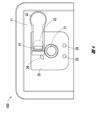
図3は、陰圧療法システム200のより詳細な実施態様例でありうる陰圧療法システム300の上面図を示す。図示のように、インタフェース要素22は、位置32において創傷被覆材13に溶着されるフィルム内に形成され得るアクティブ化部品31を含み得る。アクティブ化部品31は、インタフェース要素22のユーザ入力を受けるために使用できる。
FIG. 3 shows a top view of a negative
図4は、陰圧療法システム200のより詳細な実施態様例でありうる陰圧療法システム400の上面図を示す。図示のように、インタフェース要素22は、可撓性で、挿入用のフィルム内に構築され、位置42で創傷被覆材13に溶着され得るプリント回路基板(PCB)41を含み得る。プリント回路基板41は、インタフェース要素22のユーザ入力を受信するために使用できる。さらに、ゼロ挿入力(ZIF)コネクタのロック機構を使用して、保持を改善しうる。
FIG. 4 shows a top view of a negative
図5Aおよび図5Bは、陰圧療法システム200のより詳細な実施態様例でありうる陰圧療法システム500の上面図を示す。図示のように、インタフェース要素22は、取り付けられた時(図5Bを参照)に電気接点を完了し、取り外し時に電気接点を切断してインタフェース要素22のユーザ入力を受信するために使用され得る導電性ラベル51を含むことができる。さらに、ZIFコネクタのロック機構を使用して、保持を改善しうる。
5A and 5B illustrate top views of negative
図6は、TNP装置11などの装置による陰圧療法の送達を制御するために使用可能な療法制御プロセス600を示す。便宜上、療法制御プロセス600がTNP装置11の文脈において説明されるが、代わりに、本明細書に記載の他のシステムで、または示されていない他のシステムによって実行される場合もある。療法制御プロセス600は、一部の例において、TNP装置11の制御回路12Aによって実施され得る。
FIG. 6 illustrates a
ブロック602で、療法制御プロセス600は、無効入力がユーザから受信されたかどうかを判断できる。無効入力は、例えば、インタフェース要素22を介してユーザから受信されてもよい。一部の実施態様では、無効入力は、インタフェース要素22を介する以外のTNP装置11へのいずれのユーザ入力によっても提供されない場合がある。
At
無効入力が受信された場合、ブロック604で、療法制御プロセス600は陰圧の供給を無効にすることができる。陰圧の供給は、例えば、陰圧源12Cまたは制御回路12Aの動作の停止、流体流路内に位置付けられたベントの開放、流体流路内に位置付けられた弁の閉鎖によって無効化され得る。ブロック604の後、療法制御プロセス600は終了することができる。一部の実施態様では、ブロック604の後、TNP装置11は、スイッチ21へのユーザ入力によっては起動されなくなることがあり、そのためユーザはTNP装置11に陰圧を生成させることができなくなり得る。
If an override input is received, at
無効入力が受信されなかった場合、ブロック606で、療法制御プロセス600は、起動入力がユーザから受信されたかどうかを判断できる。起動入力は、例えば、スイッチ21を介してユーザから受信され得る。一部の実施態様では、起動入力は、スイッチ21を介する以外のTNP装置11へのいずれのユーザ入力によっても提供されない場合がある。
If an invalid input is not received, at
起動入力が受信されなかった場合、療法制御プロセス600はブロック602に戻り、再び無効入力がユーザから受信されたかどうかを判断することができる。
If an activation input was not received,
一方、起動入力が受信された場合、ブロック608で、療法制御プロセス600は陰圧を供給することができる。陰圧の供給は、陰圧源12Cによって実施することができ、陰圧は、流体流路を介して創傷被覆材13に供給することができる。
On the other hand, if an activation input is received, at
ブロック610で、療法制御プロセス600は、不停止入力がユーザから受信されたかどうかを判断できる。停止入力は、例えば、スイッチ21を介してユーザから受信されうる。一部の実施態様では、停止入力は、スイッチ21を介する以外のTNP装置11へのいずれのユーザ入力によっても提供されない場合がある。
At
停止入力がブロック612で受信された場合、療法制御プロセス600は、陰圧の供給を防止することができる。陰圧の供給は、例えば、陰圧源12Cの動作の停止、流体流路内に位置付けられたベントの開放、および流体流路内に位置付けられた弁の閉鎖のうちの一つ以上によって防止されうる。ブロック612の後、療法制御プロセス600はブロック602に戻り、再び無効入力がユーザから受信されたかどうかを判断することができる。
If a stop input is received at
停止入力がブロック614で受信された場合、療法制御プロセス600は、無効入力がユーザから受信されたかどうかを判断できる。無効入力は、例えば、インタフェース要素22を介してユーザから受信されてもよい。一部の実施態様では、無効入力は、インタフェース要素22を介する以外のTNP装置11へのいずれのユーザ入力によっても提供されない場合がある。いくつかの実施形態では陰圧の供給を無効化するかどうかを判断するために、TNP装置11が陰圧創傷療法を提供する間に、ブロック614は定期的に実行される。
If a stop input is received at
無効入力が受信されなかった場合、療法制御プロセス600はブロック608に戻り、陰圧の供給を続けることができる。
If an invalid input is not received,
無効入力が受信された場合、ブロック616で、療法制御プロセス600は陰圧の供給を無効にすることができる。陰圧の供給は、例えば、陰圧源12Cまたは制御回路12Aの動作の停止、流体流路内に位置付けられたベントの開放、流体流路内に位置付けられた弁の閉鎖によって無効化され得る。ブロック616の後、療法制御プロセス600は終了することができる。一部の実施態様では、ブロック616の後、TNP装置11は、スイッチ21へのユーザ入力によっては起動されなくなることがあり、そのためユーザはTNP装置11に陰圧を生成させることができなくなり得る。追加でまたは代替で、TNP装置11は、インタフェース要素22を介してユーザからなど、イネーブル入力が受信されるまで、スイッチ21へのユーザ入力によって起動されなくなり得る。一部の実施態様では、イネーブル入力は、インタフェース要素22を介する以外のTNP装置11へのいずれのユーザ入力によっても提供されない場合がある。
If an override input is received, at
療法制御プロセス600の一部の実施態様では、陰圧の供給は、停止入力または無効入力以外のいずれのユーザ入力によっても停止しない場合がある。
In some implementations of
図7A、図7B、図7Cは、本明細書に記載の陰圧システムの任意の実施形態と併用できるコネクタを図示する。図7Aは、例えば、スイッチ21およびインタフェース要素22を各対の回路に接続する四つの回路(またはコネクタ)70A、70B、70C、および70Dを持つヘッダ700Aを図示する。図7Bは、例えば、スイッチ21とインタフェース要素22を接続するためのSMTピンヘッダ700Bを図示する。一部の実施態様では、スイッチ21はコネクタ72Aに接続されてもよく、インタフェース要素22はコネクタ72Bに接続されてもよく、またはその逆でもよい。図7Cは、スイッチ21またはインタフェース要素22を接続できる端子74を有するZIFコネクタ700Cを図示する。いくつかの実施形態では、スイッチ21およびインタフェース要素22のそれぞれを接続するために、二つのZIFコネクタ700Cを使用できる。
7A, 7B, and 7C illustrate connectors that can be used with any of the embodiments of negative pressure systems described herein. FIG. 7A, for example, illustrates a
図8Aは、陰圧療法システム200のより詳細な実施態様例でありうる陰圧療法システム800Aの上面図を示す。タブ810Aは、創傷被覆材内の開口を引き裂いて、陰圧の送達の終了を引き起こす点線820Aに沿った大きな漏れを強制することができる。図8Bは、陰圧治療システム200のより詳細な実施態様例でありうる陰圧治療システム800Bの上面図を示す。タブ810Bは、点線820Bに沿って創傷被覆材を引き裂いて、陰圧の送達の終了を引き起こすTNP装置用の電源または電子機器を破壊する(電池または電気構成要素を除去するなど)ことができる。
FIG. 8A shows a top view of a negative
図9は、陰圧療法システム200のより詳細な実施態様例でありうる陰圧療法システムの構成要素900を示す。構成要素900は、電池が制御電子回路から分離できることを示すことができ、電池と制御電子回路との間の接続を起動機能として使用することができる。構成要素900は、図示されたように下側に表面取り付けコネクタ910を含み得る。
FIG. 9 illustrates negative pressure
図10は、陰圧療法システム200のより詳細な実施態様例でありうる陰圧療法システムの構成要素1000を示す。構成要素1000は、図示したように上面上に表面取り付けコネクタ1010を含みうる。構成要素1000は、主電気領域がリジッドPCBを含みうること、およびバッテリーアセンブリに接続するために最上面上にコネクタを持つことを図示できる。
FIG. 10 illustrates negative pressure
図11は、陰圧療法システム200のより詳細な実施態様例でありうる陰圧療法システムの構成要素1100を示す。構成要素1100は、一つ以上のその他の実施形態に対して、再分割された電子回路の配置を図示できる。ポンプは一方の側にあり、電池をパックとして追加することができる。パックは創傷被覆材に接着するため下側にシリコンを有しうる。構成要素1100は、図示されたように下側に表面取り付けコネクタを含み得る。
FIG. 11 illustrates negative pressure
図12は、陰圧療法システム200のより詳細な実施態様例でありうる陰圧療法システムの構成要素1200を示す。構成要素1200は、表面取り付けコネクタ1210がまだ上側にあるポンプモジュールの上部を図示することができる。
FIG. 12 illustrates negative pressure
他の変形
本明細書で提供される閾値、限界値、期間などの値は、絶対的なものであることを意図するものではなく、したがっておおよそのものでありうる。さらに、本明細書で提供される任意の閾値、限界値、期間などは、自動的にまたはユーザによって、固定されるかまたは変えられうる。さらに、本明細書で使用される場合、参照値に関連した、超える、超、未満などの相対的な程度を表す用語は、参照値と等しい場合も包含することが意図される。例えば、正の参照値を超えることは、参照値以上であることを包含することができる。その上、本明細書で使用される場合、参照値に関連した、超える、超、未満などの相対的な程度を表す用語は、参照値に関連した、下にある、未満、超などの開示された関係とは逆のものも包含することが意図される。また、種々のプロセスのブロックは、ある値が特定の閾値に達するかまたは達しないかを判定することに関して説明されうるが、ブロックは、例えば、ある値が(i)閾値未満であるかもしくは閾値を超えているか、または(ii)閾値を満たすかもしくは満たしていないかに関しても同様に解釈されうる。
Other Variations The values of thresholds, limits, time periods, etc. provided herein are not intended to be absolute, and therefore may be approximate. Additionally, any thresholds, limits, time periods, etc. provided herein may be fixed or varied automatically or by the user. Additionally, as used herein, terms expressing relative degrees, such as exceeding, more than, less than, in relation to a reference value are intended to encompass equality with the reference value. For example, exceeding a positive reference value can include being greater than or equal to the reference value. Additionally, as used herein, terms of relative degree, such as exceeding, more than, less than, in relation to a reference value, refer to disclosures such as below, below, less than, more than, etc. in relation to a reference value. It is intended to include the opposite relationship. Also, while blocks of various processes may be described in terms of determining whether a value reaches or does not reach a particular threshold, blocks may include, for example, determining whether a value (i) is less than or equal to a threshold; or (ii) whether the threshold value is met or not.
特定の態様、実施形態、または実施例に関連して説明される特性、物質、特徴、または群は、本明細書に記載される他の任意の態様、実施形態、または実施例に、これらと両立できないことがない限り、適用可能であることを理解されたい。本明細書(添付の任意の特許請求の範囲、要約書、及び図面を含む)に開示される全ての特徴、または同様に開示される任意の方法もしくはプロセスの全てのステップは、こうした特徴またはステップのうち少なくともいくつかが相互に排他的となる組み合わせを除いて、任意の組み合わせで組み合わされてよい。本発明の保護するものは、前述の任意の実施形態の詳細に限定されない。保護するものは、本明細書(添付の任意の特許請求の範囲、要約書、及び図面を含む)において開示される特徴のうちの任意の新規なもの、もしくは任意の新規な組み合わせに及び、または同様に開示される任意の方法またはプロセスのステップのうちの任意の新規なもの、もしくは任意の新規な組み合わせに及ぶ。 A feature, substance, feature, or group described in connection with a particular aspect, embodiment, or example may be referred to in conjunction with any other aspect, embodiment, or example described herein. Please understand that this is applicable as long as there is no incompatibility. All features disclosed in this specification (including any appended claims, abstract, and drawings) or all steps of any method or process similarly disclosed may include such features or steps. At least some of them may be combined in any combination except for mutually exclusive combinations. Coverage of the invention is not limited to the details of any of the embodiments described above. Protection extends to any novel or novel combination of features disclosed in this specification (including any appended claims, abstract, and drawings); or It also extends to any novel or novel combination of steps of any method or process disclosed.
一定の実施形態が説明されてきたが、これらの実施形態は、単に例として提示されており、保護範囲を限定することを意図するものではない。実際、本明細書に記載の新規な方法及びシステムは、様々な他の形態で具現化されてもよい。さらに、本明細書に記載の方法及びシステムの形態において、様々な省略、置換、及び変形がなされ得る。実施形態によっては、図示または開示されたプロセスにおいて実施される実際のステップは、図に示されたステップとは異なり得ることを、当業者は認識するであろう。実施形態によっては、上述したステップのうちの特定のステップが除去される場合があり、別のものが加えられる場合もある。例えば、開示されるプロセスで実施される実際のステップまたはステップの順序は、図で示したものとは異なっていてもよい。実施形態によっては、上述したステップのうちの特定のステップが除去される場合があり、別のものが加えられる場合もある。例えば、図に示した様々な構成要素が、プロセッサ、コントローラ、ASIC、FPGA、または専用ハードウェア上のソフトウェアまたはファームウェアとして実装されてもよい。プロセッサ、ASIC、FPGAなどのハードウェア構成要素には論理回路が含まれうる。さらに、上記に開示された特定の実施形態の特徴及び特性は、様々な方法で組み合わせることができ、さらなる実施形態を形成することができるが、その全てが本開示の範囲内に収まることになる。 Although certain embodiments have been described, these embodiments are presented by way of example only and are not intended to limit the scope of protection. Indeed, the novel methods and systems described herein may be embodied in a variety of other forms. Additionally, various omissions, substitutions, and variations may be made in the form of the methods and systems described herein. Those skilled in the art will recognize that in some embodiments, the actual steps performed in the illustrated or disclosed processes may differ from those shown in the figures. In some embodiments, certain of the steps described above may be removed, and others may be added. For example, the actual steps or order of steps performed in the disclosed processes may differ from that shown in the figures. In some embodiments, certain of the steps described above may be removed, and others may be added. For example, the various components illustrated in the figures may be implemented as software or firmware on a processor, controller, ASIC, FPGA, or dedicated hardware. Hardware components such as processors, ASICs, FPGAs, etc. may include logic circuits. Moreover, the features and characteristics of the particular embodiments disclosed above can be combined in various ways to form further embodiments, all of which will fall within the scope of this disclosure. .
本明細書で図示され、説明されるユーザーインタフェーススクリーンには、追加の構成要素または代替の構成要素が含まれうる。これらの構成要素には、メニュー、リスト、ボタン、テキストボックス、ラベル、ラジオボタン、スクロールバー、スライダー、チェックボックス、コンボボックス、ステータスバー、ダイアログボックス、ウィンドウなどが含まれうる。ユーザーインタフェーススクリーンには、追加の情報、または代替の情報が含まれうる。構成要素は、任意の好適な順番に配置され、グループ化され、標示されうる。 The user interface screens illustrated and described herein may include additional or alternative components. These components may include menus, lists, buttons, text boxes, labels, radio buttons, scroll bars, sliders, check boxes, combo boxes, status bars, dialog boxes, windows, and the like. User interface screens may include additional or alternative information. The components may be arranged, grouped, and labeled in any suitable order.
本開示には、特定の実施形態、実施例、及び用途が含まれるが、本開示は、具体的に開示された実施形態の範囲を超えて、他の代替の実施形態または使用ならびにその明らかな変更形及びその等価物にまで及び、これには本明細書に記載された特徴および利点の全てを提供しているとは限らない実施形態が含まれることは、当業者に理解されるであろう。したがって、本開示の範囲は、本明細書における好ましい実施形態の特定の開示によって限定されることを意図するものではなく、本明細書に提示されるまたはこの後に提示される特許請求の範囲によって画定されうる。 Although this disclosure includes particular embodiments, examples, and uses, this disclosure goes beyond the scope of the specifically disclosed embodiments, as well as other alternative embodiments or uses thereof, as well as their obvious It will be appreciated by those skilled in the art that modifications and equivalents thereof may extend and include embodiments that do not provide all of the features and advantages described herein. Dew. Accordingly, the scope of the present disclosure is not intended to be limited by the specific disclosure of preferred embodiments herein, but rather by the claims presented herein or hereafter. It can be done.
「し得る(can)」、「できる(could)」、「可能性がある(might)」、または「場合がある(may)」などの条件付き言い回しは、別途具体的に記載されない限り、または使用される文脈の範囲内で別途解釈されない限り、一定の実施形態が、特定の特徴、要素、またはステップを含む一方で、他の実施形態は含まないということの伝達を意図するのが通例である。したがって、こうした条件付き言い回しは、特徴、要素、またはステップが一つまたは複数の実施形態に多少なりとも必要とされるという示唆、またはこれらの特徴、要素、もしくはステップが特定の任意の実施形態に含まれているかどうか、もしくは該実施形態で実施されるべきかどうかを、ユーザ入力または命令の有無にかかわらず決定するためのロジックが、一つまたは複数の実施形態に必然的に含まれているという示唆を必ずしも意図するものではない。「備える(comprising)」、「含む(including)」、および「有する(having)」などの用語は、同義語であり、包含的に非限定様式で用いられ、追加の要素、特徴、行為、および動作などを排除するものではない。また、用語「または(or)」は、包括的な意味で(排他的な意味ではなく)用いられることで、例えば要素の列記をつなぐのに使用される場合、列記の要素のうちの一つ、一部、または全てを意味することになる。さらに、用語「各々」は、本明細書で使用される場合、通常の意味を有するのに加えて、用語「各々」が適用されている一連の要素の任意のサブセットも意味し得る。 Conditional phrases such as "can," "could," "might," or "may" mean that unless specifically stated otherwise, Unless otherwise interpreted within the context of use, it is generally intended to convey that certain embodiments include a particular feature, element, or step while other embodiments do not. be. Thus, such conditional language does not imply that a feature, element, or step is required in any way or in any way in one or more embodiments, or that these features, elements, or steps are required in any particular embodiment. One or more embodiments necessarily include logic for determining whether to be included or implemented in the embodiment with or without user input or instruction. It is not necessarily intended to suggest that. Terms such as "comprising," "including," and "having" are synonymous and are used in an inclusive, non-limiting manner, including additional elements, features, acts, and It does not exclude actions. Also, the term "or" is used in an inclusive (rather than an exclusive) sense, e.g. when used to connect a list of elements, one of the elements in the list , can mean some or all. Additionally, the term "each" as used herein, in addition to having its ordinary meaning, can also mean any subset of the set of elements to which the term "each" is applied.
語句「X、Y、およびZのうちの少なくとも一つ」などの連言的言い回しは、別途具体的に記載されない限り、ある項目や用語などが、Xか、Yか、Zのいずれかであり得ることを伝えるのに一般的に用いられる文脈と共に、別途解釈されるものである。したがって、こうした連言的言い回しは、特定の実施形態が、少なくともXのうちの一つと、少なくともYのうちの一つと、少なくともZのうちの一つとを含むことを必要とするという示唆を必ずしも意図するものではない。 Conjunctive expressions such as the phrase "at least one of X, Y, and Z" mean that an item, term, etc. is either X, Y, or Z, unless specifically stated otherwise. It is to be interpreted separately, along with the context commonly used to convey what is obtained. Thus, such conjunctive language is not necessarily intended to suggest that a particular embodiment requires at least one of X, at least one of Y, and at least one of Z. It's not something you do.
本明細書で使用される「およそ」、「約」、「概して」、および「実質的に」という用語などの、本明細書で使用される程度を表す言い回しは、所望の機能を依然として果たすかまたは所望の結果をもたらす所定の値、量、または特性に近い値、量、または特性を表すものである。例えば、「およそ」、「約」、「概して」、及び「実質的に」という用語は、所定の量の10%未満以内、5%未満以内、1%未満以内、0.1%未満以内、及び0.01%未満以内の量を意味し得る。別の例として、一定の実施形態において、「概して平行」及び「実質的に平行」という用語は、丁度平行である状態から15度以下、10度以下、5度以下、3度以下、1度以下、または0.1度以下ずれている値、量、または特性を意味する。 Words of degree used herein, such as the terms "approximately," "about," "generally," and "substantially," refer to the extent to which the desired function is still performed. or represents a value, amount, or characteristic that approximates a predetermined value, amount, or characteristic that produces a desired result. For example, the terms "approximately," "about," "generally," and "substantially" mean within less than 10%, within less than 5%, within less than 1%, within less than 0.1% of a given amount; and an amount within 0.01%. As another example, in certain embodiments, the terms "generally parallel" and "substantially parallel" refer to less than 15 degrees, less than 10 degrees, less than 5 degrees, less than 3 degrees, less than 1 degree from exactly parallel. means a value, quantity, or property that deviates by less than or equal to or less than 0.1 degree.
本開示の範囲は、本節におけるまたは本明細書の他の箇所における好ましい実施形態の
特定の開示によって制限されることを意図するものではなく、本節においてまたは本明細書の他の箇所において提示されているか、またはこの後に提示される特許請求の範囲によって定義されうる。本特許請求の範囲の言い回しは、本特許請求の範囲で用いられている言い回しに基づいて広い意味で解釈されるべきであり、本明細書で説明されている例または本出願の手続きの間に説明される例に限定されるものではなく、それらの例は非排他的なものとして解釈されるべきである。
[付記項1]
創傷に陰圧を加える装置であって、
患者の創傷上に配置されるように構成された創傷被覆材と、
前記創傷被覆材上または前記創傷被覆材内に配置された陰圧源であって、流体流路を介して陰圧を前記創傷被覆材に提供するように構成された、陰圧源と、
前記創傷被覆材上または前記創傷被覆材内に配置されたスイッチであって、第一のユーザ入力を受信するように構成される、スイッチと、
前記創傷被覆材上または前記創傷被覆材内に配置されたインタフェース要素であって、第二のユーザ入力を受信するように構成される、インタフェース要素と、
前記スイッチおよび前記インタフェース要素に電気的に連結された制御回路であって、前記制御回路が、
第一のモードにあるとき、
前記陰圧源が陰圧を供給していない間に、前記第一のユーザ入力の受信に応答して前記陰圧源で陰圧を供給し、
前記陰圧源が陰圧を供給している間に、前記第一のユーザ入力の受信に応答して前記陰圧源で陰圧を供給することを防止し、
前記第二のユーザ入力の受信に応答して、前記第一のモードから前記第一のモードとは異なる第二のモードに変更し、
前記第二のモードにあるとき、前記陰圧源での陰圧の供給を無効にするように構成される、制御回路と、を備える、装置。
[付記項2]
前記スイッチがフォルトを経験し、前記第一のユーザ入力を受信することができなくなった時、前記制御回路が、前記第二のユーザ入力以外のユーザ入力の受信をしないことに応答して、前記陰圧源での陰圧の供給を防止または無効化するようにさらに構成される、付記項1に記載の装置。
[付記項3]
前記制御回路が、前記第一のユーザ入力以外のユーザ入力の受信をしないことに応答して、前記陰圧源で陰圧を供給するようにさらに構成される、付記項1に記載の装置。
[付記項4]
前記陰圧源が陰圧を供給している間、前記制御回路が、前記第一のユーザ入力および前記第二のユーザ入力以外のユーザ入力の受信をしないことに応答して、前記陰圧源での陰圧の供給を防止または無効化するようにさらに構成される、付記項1に記載の装置。
[付記項5]
前記制御回路が前記第二のモードにあるとき、前記制御回路が、前記第二のユーザ入力の受信に応答して、
第二のモードから第一のモードへ変更し、
前記陰圧源で陰圧を供給するようにさらに構成される、付記項1に記載の装置。
[付記項6]
前記制御回路が、前記陰圧源または前記制御回路の動作の停止、前記流体流路内に位置付けられたベントの開放、または前記流体流路内に位置付けられた弁の閉鎖によって、前記陰圧源での陰圧の供給を無効化するように構成される、付記項1に記載の装置。
[付記項7]
前記制御回路が、(i)前記陰圧源または前記制御回路への電力の切断、または(ii)前記陰圧源または前記制御回路に提供されるイネーブル信号の取消によって、前記陰圧源または前記制御回路の動作を停止するように構成される、付記項6に記載の装置。
[付記項8]
前記制御回路が、前記陰圧源の動作の停止、前記流体流路内に位置付けられたベントの開放、または前記流体流路内に位置付けられた弁の閉鎖によって、前記陰圧源での陰圧の供給を防止するように構成される、付記項1に記載の装置。
[付記項9]
前記インタフェース要素が、前記創傷被覆材に結合されたフィルム内に成形される、付記項1に記載の装置。
[付記項10]
前記インタフェース要素が、前記第二のユーザ入力を受信するように構成された電気接点を備える、付記項1に記載の装置。
[付記項11]
前記スイッチが、一定期間の間、前記スイッチの押下げに応答して前記第一のユーザ入力を受信するように構成される、付記項1に記載の装置。
[付記項12]
前記期間が0.5秒~5秒である、付記項11に記載の装置。
[付記項13]
創傷被覆材、前記創傷被覆材上または前記創傷被覆材内に配置された陰圧源、前記創傷被覆材上または前記創傷被覆材内に配置されたスイッチ、および前記創傷被覆材上または前記創傷被覆材内に配置されたインタフェース要素を備え、前記スイッチが第一のユーザ入力を受信するように構成され、前記インタフェース要素が第二のユーザ入力を受信するように構成される、陰圧療法装置を動作される方法であって、
前記陰圧源が前記創傷被覆材に陰圧を供給していない間に、前記第一のユーザ入力の受信に応答して、流体流路を介して前記創傷被覆材に前記陰圧源で陰圧を供給することと、
前記陰圧源が前記創傷被覆材に陰圧を供給している間、前記第一のユーザ入力の受信に応答して、前記流体流路を介して前記創傷被覆材に前記陰圧源で陰圧を供給することを防止することと、
前記第二のユーザ入力の受信に応答して、前記創傷被覆材に前記陰圧源で陰圧源を供給することを無効化することと、
前記陰圧の供給の無効化の後に、前記第一のユーザ入力の受信に応答して、前記流体流路を介して前記創傷被覆材に前記陰圧源で陰圧を供給しないことと、を含む、方法。
[付記項14]
前記スイッチがフォルトを経験し、前記第一のユーザ入力を受信できなくなることに続いて、前記第二のユーザ入力以外のユーザ入力の受信をしないことに応答して、前記陰圧源での陰圧の供給を防止または無効化することをさらに含む、付記項13に記載の方法。
[付記項15]
前記第一のユーザ入力以外のユーザ入力の受信をしないことに応答して、前記陰圧源で陰圧を供給することをさらに含む、付記項13に記載の方法。
[付記項16]
前記陰圧源が陰圧を供給している間、前記第一のユーザ入力および前記第二のユーザ入力以外のユーザ入力の受信をしないことに応答して、前記陰圧源での陰圧の供給を防止または無効化することをさらに含む、付記項13に記載の方法。
[付記項17]
前記陰圧の供給の無効化が、前記陰圧源または前記制御回路の動作の停止、前記流体流路内に位置付けられたベントの開放、または前記流体流路内に位置付けられた弁の閉鎖を含む、付記項13に記載の方法。
[付記項18]
前記インタフェース要素の電気接点を介して前記第二のユーザ入力を受信することをさらに含む、付記項13に記載の方法。
[付記項19]
一定期間の間、前記スイッチの押下げに応答して前記第一のユーザ入力を受信することをさらに含む、付記項13に記載の方法。
[付記項20]
前記期間が0.5秒~5秒である、付記項19に記載の方法。
The scope of the present disclosure is not intended to be limited by the specific disclosure of preferred embodiments in this section or elsewhere herein, or provided herein or elsewhere herein. or may be defined by the claims hereinafter presented. The language of this claim should be interpreted broadly based on the language used in the claims, and the language used in the examples described herein or in the proceedings of this application shall be interpreted broadly. There is no limitation to the illustrated examples, which should be construed as non-exclusive.
[Additional note 1]
A device that applies negative pressure to a wound,
a wound dressing configured to be placed over a wound of a patient;
a negative pressure source disposed on or within the wound dressing and configured to provide negative pressure to the wound dressing via a fluid flow path;
a switch disposed on or within the wound dressing and configured to receive a first user input;
an interface element disposed on or within the wound dressing and configured to receive a second user input;
a control circuit electrically coupled to the switch and the interface element, the control circuit comprising:
When in the first mode,
providing negative pressure at the negative pressure source in response to receiving the first user input while the negative pressure source is not providing negative pressure;
while the negative pressure source is providing negative pressure, preventing the negative pressure source from providing negative pressure in response to receiving the first user input;
in response to receiving the second user input, changing from the first mode to a second mode different from the first mode;
and a control circuit configured to disable the supply of negative pressure at the negative pressure source when in the second mode.
[Additional note 2]
When the switch experiences a fault and is unable to receive the first user input, the control circuit is responsive to not receiving any user input other than the second user input; 2. The apparatus of clause 1, further configured to prevent or disable the supply of negative pressure at the negative pressure source.
[Additional note 3]
2. The apparatus of clause 1, wherein the control circuit is further configured to provide negative pressure at the negative pressure source in response to not receiving user input other than the first user input.
[Additional note 4]
In response to the control circuit not receiving user input other than the first user input and the second user input while the negative pressure source is providing negative pressure, the negative pressure source 2. The apparatus of clause 1, further configured to prevent or disable the supply of negative pressure at the apparatus.
[Additional note 5]
When the control circuit is in the second mode, the control circuit is responsive to receiving the second user input;
Change from second mode to first mode,
2. The apparatus of clause 1, further configured to provide negative pressure with the negative pressure source.
[Additional note 6]
The control circuit may cause the source of negative pressure to be removed by ceasing operation of the source of negative pressure or the control circuit, opening a vent located within the fluid flow path, or closing a valve located within the fluid flow path. Apparatus according to clause 1, configured to disable the supply of negative pressure at.
[Additional note 7]
The control circuit is configured to control the negative pressure source or the control circuit by (i) disconnecting power to the negative pressure source or the control circuit, or (ii) canceling an enable signal provided to the negative pressure source or the control circuit. 7. The apparatus of clause 6, configured to stop operation of the control circuit.
[Additional Note 8]
The control circuit reduces the negative pressure at the negative pressure source by ceasing operation of the negative pressure source, opening a vent located within the fluid flow path, or closing a valve located within the fluid flow path. Apparatus according to clause 1, configured to prevent the supply of.
[Additional Note 9]
2. The device of clause 1, wherein the interface element is molded into a film bonded to the wound dressing.
[Additional Note 10]
2. The apparatus of clause 1, wherein the interface element comprises electrical contacts configured to receive the second user input.
[Additional Note 11]
2. The apparatus of clause 1, wherein the switch is configured to receive the first user input in response to pressing the switch for a period of time.
[Additional Note 12]
Apparatus according to
[Additional Note 13]
a wound dressing, a negative pressure source disposed on or in the wound dressing, a switch disposed on or in the wound dressing, and on or in the wound dressing. a negative pressure therapy device comprising an interface element disposed within a material, the switch configured to receive a first user input, and the interface element configured to receive a second user input. A method of operating,
In response to receiving the first user input, applying negative pressure to the wound dressing via a fluid flow path while the negative pressure source is not applying negative pressure to the wound dressing. supplying pressure;
In response to receiving the first user input, applying negative pressure to the wound dressing via the fluid flow path while the negative pressure source is applying negative pressure to the wound dressing. preventing the supply of pressure;
in response to receiving the second user input, disabling providing a source of negative pressure to the wound dressing with the source of negative pressure;
after disabling the supply of negative pressure, in response to receiving the first user input, not providing negative pressure with the source of negative pressure to the wound dressing via the fluid flow path; Including, methods.
[Additional Note 14]
negative pressure at the source of negative pressure in response to the switch experiencing a fault and failing to receive user input other than the second user input; 14. The method of
[Additional Note 15]
14. The method of
[Additional Note 16]
in response to not receiving user input other than the first user input and the second user input while the negative pressure source is providing negative pressure; 14. The method of
[Additional Note 17]
Disabling the supply of negative pressure includes ceasing operation of the source of negative pressure or the control circuit, opening a vent located within the fluid flow path, or closing a valve located within the fluid flow path. The method according to
[Additional Note 18]
14. The method of
[Additional Note 19]
14. The method of
[Additional Note 20]
The method according to clause 19, wherein the period is between 0.5 seconds and 5 seconds.
Claims (7)
患者の創傷上に配置されるように構成された創傷被覆材と、
前記創傷被覆材上または前記創傷被覆材内に配置された陰圧源であって、流体流路を介して陰圧を前記創傷被覆材に提供するように構成された、陰圧源と、
前記創傷被覆材上または前記創傷被覆材内に配置されたスイッチであって、前記陰圧源による陰圧の供給を制御するために起動入力を受信するように構成される、スイッチと、
前記創傷被覆材上または前記創傷被覆材内に配置されたインタフェース要素であって、前記インタフェース要素は、取り付けられた時に電気接点を完了しかつ取り外し時に電気接点を切断する導電性ラベルを含む、インタフェース要素と、
前記スイッチおよび前記インタフェース要素に電気的に連結された制御回路であって、前記制御回路が、
前記陰圧源が陰圧を供給していない間に、前記起動入力の受信に応答して前記陰圧源で陰圧を供給し、
前記陰圧源が陰圧を供給している間に、前記起動入力の受信に応答して前記陰圧源で陰圧を供給することを防止し、
前記インタフェース要素の前記導電性ラベルを取り外したとき、前記陰圧源での陰圧の供給を無効にするように構成される、制御回路と、を備える、装置。 A device that applies negative pressure to a wound,
a wound dressing configured to be placed over a wound of a patient;
a negative pressure source disposed on or within the wound dressing and configured to provide negative pressure to the wound dressing via a fluid flow path;
a switch disposed on or in the wound dressing and configured to receive an activation input to control the supply of negative pressure by the negative pressure source;
an interface element disposed on or within the wound dressing, the interface element comprising an electrically conductive label that completes the electrical contact when attached and breaks the electrical contact when removed; element and
a control circuit electrically coupled to the switch and the interface element, the control circuit comprising :
providing negative pressure at the negative pressure source in response to receiving the activation input while the negative pressure source is not providing negative pressure;
preventing the negative pressure source from providing negative pressure in response to receiving the activation input while the negative pressure source is providing negative pressure;
a control circuit configured to disable the supply of negative pressure at the negative pressure source when the conductive label of the interface element is removed .
Applications Claiming Priority (3)
| Application Number | Priority Date | Filing Date | Title |
|---|---|---|---|
| US201762468796P | 2017-03-08 | 2017-03-08 | |
| US62/468,796 | 2017-03-08 | ||
| PCT/EP2018/055698 WO2018162613A1 (en) | 2017-03-08 | 2018-03-08 | Negative pressure wound therapy device control in presence of fault condition |
Publications (3)
| Publication Number | Publication Date |
|---|---|
| JP2020509822A JP2020509822A (en) | 2020-04-02 |
| JP2020509822A5 JP2020509822A5 (en) | 2021-04-15 |
| JP7361606B2 true JP7361606B2 (en) | 2023-10-16 |
Family
ID=61617018
Family Applications (1)
| Application Number | Title | Priority Date | Filing Date |
|---|---|---|---|
| JP2019548398A Active JP7361606B2 (en) | 2017-03-08 | 2018-03-08 | Control of negative pressure wound therapy devices in the presence of fault conditions |
Country Status (8)
| Country | Link |
|---|---|
| US (2) | US11123471B2 (en) |
| EP (1) | EP3592312B1 (en) |
| JP (1) | JP7361606B2 (en) |
| CN (1) | CN110582257B (en) |
| AU (1) | AU2018229808B2 (en) |
| CA (1) | CA3055664A1 (en) |
| WO (1) | WO2018162613A1 (en) |
| ZA (1) | ZA201905812B (en) |
Families Citing this family (34)
| Publication number | Priority date | Publication date | Assignee | Title |
|---|---|---|---|---|
| GB0808376D0 (en) | 2008-05-08 | 2008-06-18 | Bristol Myers Squibb Co | Wound dressing |
| GB0817796D0 (en) | 2008-09-29 | 2008-11-05 | Convatec Inc | wound dressing |
| GB201020236D0 (en) | 2010-11-30 | 2011-01-12 | Convatec Technologies Inc | A composition for detecting biofilms on viable tissues |
| WO2012078781A1 (en) | 2010-12-08 | 2012-06-14 | Convatec Technologies Inc. | Integrated system for assessing wound exudates |
| CN103347562B (en) | 2010-12-08 | 2016-08-10 | 康沃特克科技公司 | Wound exudate system accessory |
| GB201115182D0 (en) | 2011-09-02 | 2011-10-19 | Trio Healthcare Ltd | Skin contact material |
| GB2497406A (en) | 2011-11-29 | 2013-06-12 | Webtec Converting Llc | Dressing with a perforated binder layer |
| US20150354096A1 (en) | 2012-12-20 | 2015-12-10 | Convatec Technologies Inc. | Processing of chemically modified cellulosic fibres |
| US11740241B2 (en) | 2016-03-30 | 2023-08-29 | Synovo Gmbh | Construct including an anchor, an enzyme recognition site and an indicator region for detecting microbial infection in wounds |
| CN109310528B (en) | 2016-03-30 | 2021-07-20 | 康沃特克科技公司 | Detecting microbial infection in a wound |
| EP4049692A1 (en) | 2016-04-26 | 2022-08-31 | Smith & Nephew PLC | Wound dressings and methods of use with integrated negative pressure source having a fluid ingress inhibition component |
| JP6975170B2 (en) | 2016-05-03 | 2021-12-01 | スミス アンド ネフュー ピーエルシーSmith & Nephew Public Limited Company | Optimization of power transfer to negative pressure sources in negative pressure therapy systems |
| WO2017191158A1 (en) | 2016-05-03 | 2017-11-09 | Smith & Nephew Plc | Systems and methods for driving negative pressure sources in negative pressure therapy systems |
| WO2017191154A1 (en) | 2016-05-03 | 2017-11-09 | Smith & Nephew Plc | Negative pressure wound therapy device activation and control |
| CA3030151A1 (en) | 2016-07-08 | 2018-01-11 | Convatec Technologies Inc. | Fluid collection apparatus |
| JP7071957B2 (en) | 2016-07-08 | 2022-05-19 | コンバテック・テクノロジーズ・インコーポレイテッド | Flexible negative pressure system |
| CA3030153C (en) | 2016-07-08 | 2023-10-24 | Convatec Technologies Inc. | Fluid flow sensing |
| EP3503857B1 (en) | 2016-08-25 | 2024-04-17 | Smith & Nephew plc | Absorbent negative pressure wound therapy dressing |
| WO2018060417A1 (en) | 2016-09-30 | 2018-04-05 | Smith & Nephew Plc | Negative pressure wound treatment apparatuses and methods with integrated electronics |
| EP3592312B1 (en) | 2017-03-08 | 2024-01-10 | Smith & Nephew plc | Negative pressure wound therapy device control in presence of fault condition |
| US11160915B2 (en) | 2017-05-09 | 2021-11-02 | Smith & Nephew Plc | Redundant controls for negative pressure wound therapy systems |
| GB201718070D0 (en) | 2017-11-01 | 2017-12-13 | Smith & Nephew | Negative pressure wound treatment apparatuses and methods with integrated electronics |
| EP3681550B1 (en) | 2017-09-13 | 2023-11-08 | Smith & Nephew PLC | Negative pressure wound treatment apparatuses |
| GB201718072D0 (en) | 2017-11-01 | 2017-12-13 | Smith & Nephew | Negative pressure wound treatment apparatuses and methods with integrated electronics |
| GB201718054D0 (en) | 2017-11-01 | 2017-12-13 | Smith & Nephew | Sterilization of integrated negative pressure wound treatment apparatuses and sterilization methods |
| EP3703632B1 (en) | 2017-11-01 | 2024-04-03 | Smith & Nephew plc | Negative pressure wound treatment apparatuses and methods with integrated electronics |
| US10624794B2 (en) | 2018-02-12 | 2020-04-21 | Healyx Labs, Inc. | Negative pressure wound therapy systems, devices, and methods |
| USD898925S1 (en) | 2018-09-13 | 2020-10-13 | Smith & Nephew Plc | Medical dressing |
| EP3902574B1 (en) * | 2018-12-26 | 2023-05-24 | KCI Licensing, Inc. | Piezoelectric pump adapter for negative-pressure therapy |
| US11484640B2 (en) * | 2019-07-03 | 2022-11-01 | T.J.Smith And Nephew, Limited | Negative pressure wound therapy dressing recognition, wound status detection, and therapy adjustment |
| US11766822B2 (en) | 2019-08-20 | 2023-09-26 | 3M Innovative Properties Company | Microstructured surface with increased microorganism removal when cleaned, articles and methods |
| US11331221B2 (en) | 2019-12-27 | 2022-05-17 | Convatec Limited | Negative pressure wound dressing |
| US11771819B2 (en) | 2019-12-27 | 2023-10-03 | Convatec Limited | Low profile filter devices suitable for use in negative pressure wound therapy systems |
| CN114469518B (en) * | 2022-01-27 | 2023-02-21 | 长沙海润生物技术有限公司 | Dressing for negative-voltage electric field coupling strong-oxygen therapy |
Citations (4)
| Publication number | Priority date | Publication date | Assignee | Title |
|---|---|---|---|---|
| US20120136325A1 (en) | 2010-09-20 | 2012-05-31 | Smith & Nephew Plc | Systems and methods for controlling operation of a reduced pressure therapy system |
| JP2015510803A (en) | 2012-03-20 | 2015-04-13 | スミス アンド ネフュー ピーエルシーSmith & Nephew Public Limited Company | Operation control of decompression therapy system based on dynamic determination of duty cycle threshold |
| JP2015514451A (en) | 2012-03-12 | 2015-05-21 | スミス アンド ネフュー ピーエルシーSmith & Nephew Public Limited Company | Pressure reducing apparatus and method |
| JP2016517318A (en) | 2013-03-14 | 2016-06-16 | スミス アンド ネフュー インコーポレーテッド | System and method for administering decompression therapy |
Family Cites Families (350)
| Publication number | Priority date | Publication date | Assignee | Title |
|---|---|---|---|---|
| US3874387A (en) | 1972-07-05 | 1975-04-01 | Pasquale P Barbieri | Valved hemostatic pressure cap |
| US4224941A (en) | 1978-11-15 | 1980-09-30 | Stivala Oscar G | Hyperbaric treatment apparatus |
| US4398910A (en) | 1981-02-26 | 1983-08-16 | Blake L W | Wound drain catheter |
| US4534356A (en) | 1982-07-30 | 1985-08-13 | Diamond Shamrock Chemicals Company | Solid state transcutaneous blood gas sensors |
| US4569674A (en) | 1982-08-03 | 1986-02-11 | Stryker Corporation | Continuous vacuum wound drainage system |
| DE3323973A1 (en) | 1983-07-02 | 1985-01-03 | Boehringer Mannheim Gmbh, 6800 Mannheim | ERYTHROCYTE RETENTION SUBSTRATES |
| US4624656A (en) | 1983-07-25 | 1986-11-25 | Hospitak, Inc. | Hyperbaric gas treatment device |
| DE3441891A1 (en) | 1984-11-16 | 1986-05-28 | Walter Beck | METHOD AND DEVICE FOR SUCTIONING SECRETARY LIQUID FROM A Wound |
| DE3601363A1 (en) | 1986-01-18 | 1988-12-29 | Stierlen Maquet Ag | ELECTRICAL SWITCHING ELEMENT |
| US5527293A (en) | 1989-04-03 | 1996-06-18 | Kinetic Concepts, Inc. | Fastening system and method |
| US5056510A (en) | 1989-04-13 | 1991-10-15 | The Kendall Company | Vented wound dressing |
| US4979944A (en) | 1989-08-21 | 1990-12-25 | The Pullman Company | Surgical vacuum evacuation device |
| US5181905A (en) | 1989-11-28 | 1993-01-26 | Eric Flam | Method of monitoring the condition of the skin or wound |
| US5152757A (en) | 1989-12-14 | 1992-10-06 | Brigham And Women's Hospital | System for diagnosis and treatment of wounds |
| US5055198A (en) | 1990-03-07 | 1991-10-08 | Shettigar U Ramakrishna | Autologous blood recovery membrane system and method |
| JPH04354722A (en) | 1991-05-30 | 1992-12-09 | Nippondenso Co Ltd | Electronic tag |
| US5340968A (en) | 1991-05-07 | 1994-08-23 | Nippondenso Company, Ltd. | Information storage medium with electronic and visual areas |
| US5636643A (en) | 1991-11-14 | 1997-06-10 | Wake Forest University | Wound treatment employing reduced pressure |
| US5266928A (en) | 1992-05-29 | 1993-11-30 | Johnson Lonnie G | Wet diaper detector |
| US5964723A (en) | 1992-06-19 | 1999-10-12 | Augustine Medical, Inc. | Normothermic tissue heating wound covering |
| USD357743S (en) | 1992-12-31 | 1995-04-25 | Alza Corporation | Electrotransport drug delivery system |
| US5902256A (en) | 1993-02-12 | 1999-05-11 | Jb Research, Inc. | Massage unit with replaceable hot and cold packs |
| GB9400994D0 (en) | 1994-01-20 | 1994-03-16 | Bristol Myers Squibb Co | Wound dressing |
| US5549584A (en) | 1994-02-14 | 1996-08-27 | The Kendall Company | Apparatus for removing fluid from a wound |
| AU698477B2 (en) | 1994-08-22 | 1998-10-29 | Kci Licensing, Inc. | Wound drainage equipment |
| US6599262B1 (en) | 1994-12-07 | 2003-07-29 | Masini Michael A | Bandage with thermal insert |
| US5643189A (en) | 1994-12-07 | 1997-07-01 | Masini; Michael A. | Composite wound dressing including inversion means |
| US6225523B1 (en) | 1994-12-07 | 2001-05-01 | Masini Michael A | Invertible wound dressings and method of making the same |
| US6261276B1 (en) | 1995-03-13 | 2001-07-17 | I.S.I. International, Inc. | Apparatus for draining surgical wounds |
| US5779657A (en) | 1995-07-21 | 1998-07-14 | Daneshvar; Yousef | Nonstretchable wound cover and protector |
| GB9523253D0 (en) | 1995-11-14 | 1996-01-17 | Mediscus Prod Ltd | Portable wound treatment apparatus |
| US6783328B2 (en) | 1996-09-30 | 2004-08-31 | Terumo Cardiovascular Systems Corporation | Method and apparatus for controlling fluid pumps |
| DE19722075C1 (en) | 1997-05-27 | 1998-10-01 | Wilhelm Dr Med Fleischmann | Medication supply to open wounds |
| US6071267A (en) | 1998-02-06 | 2000-06-06 | Kinetic Concepts, Inc. | Medical patient fluid management interface system and method |
| US6458109B1 (en) | 1998-08-07 | 2002-10-01 | Hill-Rom Services, Inc. | Wound treatment apparatus |
| US6168800B1 (en) | 1998-08-20 | 2001-01-02 | Medwrap Corporation | Antimcrobial multi-layer island dressing |
| DE19844355A1 (en) | 1998-09-28 | 2000-04-06 | Rainer E Sachse | Adhesive wound dressing of flexible, membrane like material penetrable by air comprises integrated device which drains wound secretions or produces reduced pressure, or can be connected to an external suction system |
| GB9822341D0 (en) | 1998-10-13 | 1998-12-09 | Kci Medical Ltd | Negative pressure therapy using wall suction |
| CA2371888A1 (en) | 1999-06-18 | 2000-12-28 | University Of Virginia | An apparatus for fluid transport and related method thereof |
| US6261283B1 (en) | 1999-08-31 | 2001-07-17 | Alcon Universal Ltd. | Liquid venting surgical system and cassette |
| US6800074B2 (en) | 1999-11-29 | 2004-10-05 | Hill-Rom Services, Inc. | Wound treatment apparatus |
| US6183438B1 (en) | 2000-01-04 | 2001-02-06 | Ramon Berguer | Catheter with centering wire |
| US20050119737A1 (en) | 2000-01-12 | 2005-06-02 | Bene Eric A. | Ocular implant and methods for making and using same |
| DE20000887U1 (en) | 2000-01-19 | 2001-06-07 | Riesinger Geb Dahlmann | Collection bag with suction device |
| US6794554B2 (en) | 2000-02-01 | 2004-09-21 | Ferris Pharmaceuticals, Inc. | Wound packing material |
| JP2004509658A (en) | 2000-05-22 | 2004-04-02 | コフィー,アーサー,シー. | Combination of small intestinal submucosa and vacuum bandage and its use |
| US6685681B2 (en) | 2000-11-29 | 2004-02-03 | Hill-Rom Services, Inc. | Vacuum therapy and cleansing dressing for wounds |
| US6855135B2 (en) | 2000-11-29 | 2005-02-15 | Hill-Rom Services, Inc. | Vacuum therapy and cleansing dressing for wounds |
| US6976977B2 (en) | 2000-12-06 | 2005-12-20 | Sherwood Services Ag | Vacuum setting and indication system for a drainage device |
| EP1418954A2 (en) | 2001-01-18 | 2004-05-19 | Nawa-Heilmittel Gmbh | Dressing material in addition to treatment solution for use with said dressing material |
| US7700819B2 (en) | 2001-02-16 | 2010-04-20 | Kci Licensing, Inc. | Biocompatible wound dressing |
| US7070584B2 (en) | 2001-02-20 | 2006-07-04 | Kci Licensing, Inc. | Biocompatible wound dressing |
| US7108683B2 (en) | 2001-04-30 | 2006-09-19 | Kci Licensing, Inc | Wound therapy and tissue management system and method with fluid differentiation |
| DK1406567T3 (en) | 2001-07-12 | 2010-05-31 | Kci Medical Resources | Controlling the rate of vacuum change |
| US7004915B2 (en) | 2001-08-24 | 2006-02-28 | Kci Licensing, Inc. | Negative pressure assisted tissue treatment system |
| US6636010B1 (en) | 2001-10-01 | 2003-10-21 | Zevex, Inc. | Precision dosage apparatus, system and method |
| US6787682B2 (en) | 2001-11-05 | 2004-09-07 | Hollister Incorporated | Absorbent foam wound dressing |
| US7645253B2 (en) | 2001-11-16 | 2010-01-12 | National Quality Care, Inc. | Wearable ultrafiltration device |
| US6648862B2 (en) | 2001-11-20 | 2003-11-18 | Spheric Products, Ltd. | Personally portable vacuum desiccator |
| GB2382305B (en) | 2001-11-23 | 2004-12-15 | Johnson & Johnson Medical Ltd | Absorbent wound dressings containing a hydrogel layer |
| EP1627662B1 (en) | 2004-06-10 | 2011-03-02 | Candela Corporation | Apparatus for vacuum-assisted light-based treatments of the skin |
| US7534927B2 (en) | 2001-12-26 | 2009-05-19 | Hill-Rom Services, Inc. | Vacuum bandage packing |
| EP1478313B2 (en) | 2001-12-26 | 2018-03-07 | KCI Medical Resources | Vented vacuum bandage |
| CA2477674A1 (en) | 2002-02-28 | 2003-09-12 | Jeffrey S. Lockwood | External catheter access to vacuum bandage |
| US6942633B2 (en) | 2002-03-22 | 2005-09-13 | Twin Star Medical, Inc. | System for treating tissue swelling |
| US8168848B2 (en) | 2002-04-10 | 2012-05-01 | KCI Medical Resources, Inc. | Access openings in vacuum bandage |
| DE20207356U1 (en) | 2002-05-08 | 2003-06-12 | Riesinger Birgit | Absorbent body for connection to skin and mucous membrane surfaces |
| US20030212357A1 (en) | 2002-05-10 | 2003-11-13 | Pace Edgar Alan | Method and apparatus for treating wounds with oxygen and reduced pressure |
| AU2003238836A1 (en) | 2002-05-31 | 2003-12-19 | Hill-Rom Services, Inc. | Wound treatment apparatus |
| US7896856B2 (en) | 2002-08-21 | 2011-03-01 | Robert Petrosenko | Wound packing for preventing wound closure |
| US7846141B2 (en) | 2002-09-03 | 2010-12-07 | Bluesky Medical Group Incorporated | Reduced pressure treatment system |
| US7520872B2 (en) | 2002-09-13 | 2009-04-21 | Neogen Technologies, Inc. | Closed wound drainage system |
| US6979324B2 (en) | 2002-09-13 | 2005-12-27 | Neogen Technologies, Inc. | Closed wound drainage system |
| US7815616B2 (en) | 2002-09-16 | 2010-10-19 | Boehringer Technologies, L.P. | Device for treating a wound |
| GB0224986D0 (en) | 2002-10-28 | 2002-12-04 | Smith & Nephew | Apparatus |
| US20040087884A1 (en) | 2002-10-31 | 2004-05-06 | Haddock Teresa H. | Textured breathable films and their use as backing material for bandages |
| US7612248B2 (en) | 2002-12-19 | 2009-11-03 | 3M Innovative Properties Company | Absorbent medical articles |
| US7304202B2 (en) | 2002-12-31 | 2007-12-04 | Ossur Hf | Wound dressing |
| US6951553B2 (en) | 2002-12-31 | 2005-10-04 | Kci Licensing, Inc | Tissue closure treatment system and method with externally-applied patient interface |
| US7976519B2 (en) | 2002-12-31 | 2011-07-12 | Kci Licensing, Inc. | Externally-applied patient interface system and method |
| WO2005008578A2 (en) | 2003-07-07 | 2005-01-27 | Avery Dennison Corporation | Rfid device with changeable characteristics |
| JP2007529089A (en) | 2003-07-11 | 2007-10-18 | トライボテック,インコーポレイテッド | Multi-contact woven electrical switch |
| US20050033211A1 (en) | 2003-08-08 | 2005-02-10 | Samuel Scheinberg | Friction reducing bandage |
| US7942866B2 (en) | 2003-08-28 | 2011-05-17 | Boehringer Technologies, L.P. | Device for treating a wound |
| US7361184B2 (en) | 2003-09-08 | 2008-04-22 | Joshi Ashok V | Device and method for wound therapy |
| EP1673139A2 (en) | 2003-09-10 | 2006-06-28 | Power Paper Ltd. | Disposable electric bandage |
| US7531711B2 (en) | 2003-09-17 | 2009-05-12 | Ossur Hf | Wound dressing and method for manufacturing the same |
| US20050065471A1 (en) | 2003-09-23 | 2005-03-24 | Charles Kuntz | Continuous safe suction device |
| GB2432321B (en) | 2003-09-30 | 2007-10-17 | Synapse Medical Solutions Ltd | Dressing for tissue treatment |
| GB0325129D0 (en) | 2003-10-28 | 2003-12-03 | Smith & Nephew | Apparatus in situ |
| JP4660171B2 (en) | 2004-02-05 | 2011-03-30 | 阿蘇製薬株式会社 | Emergency bandage |
| US8062272B2 (en) | 2004-05-21 | 2011-11-22 | Bluesky Medical Group Incorporated | Flexible reduced pressure treatment appliance |
| US7776028B2 (en) | 2004-04-05 | 2010-08-17 | Bluesky Medical Group Incorporated | Adjustable overlay reduced pressure wound treatment system |
| US8529548B2 (en) | 2004-04-27 | 2013-09-10 | Smith & Nephew Plc | Wound treatment apparatus and method |
| GB2415382A (en) | 2004-06-21 | 2005-12-28 | Johnson & Johnson Medical Ltd | Wound dressings for vacuum therapy |
| MY139135A (en) | 2004-06-30 | 2009-08-28 | Uni Charm Corp | Disposable wearing article |
| US7104767B2 (en) | 2004-07-19 | 2006-09-12 | Wilson Greatbatch Technologies, Inc. | Diaphragm pump for medical applications |
| DE502005007667D1 (en) | 2004-09-20 | 2009-08-20 | Medela Holding Ag | DIAPHRAGM PUMP WITH VENTILATION VALVE |
| US7030329B1 (en) | 2004-10-22 | 2006-04-18 | Solectron Invotronics | Switch contact |
| DE202004017052U1 (en) | 2004-11-02 | 2005-06-09 | Riesinger, Birgit | Device for wound treatment using negative pressure |
| US7371270B2 (en) | 2004-11-24 | 2008-05-13 | Welland Medical Limited | Odour absorbing filters |
| DE202004018245U1 (en) | 2004-11-24 | 2005-07-07 | Riesinger, Birgit | Drainage device for treating wounds using reduced pressure has absorption body with layer(s) of textile section enriched with super-absorbents enclosed by liquid transmissive sleeve; absorbed wound secretions remain in absorption body |
| US7161056B2 (en) | 2005-01-28 | 2007-01-09 | Ossur Hf | Wound dressing and method for manufacturing the same |
| DE102005007016A1 (en) | 2005-02-15 | 2006-08-24 | Fleischmann, Wilhelm, Dr.med. | Device for the treatment of wounds |
| GB0508194D0 (en) | 2005-04-22 | 2005-06-01 | The Technology Partnership Plc | Pump |
| US20080097291A1 (en) | 2006-08-23 | 2008-04-24 | Hanson Ian B | Infusion pumps and methods and delivery devices and methods with same |
| US7503910B2 (en) | 2006-02-01 | 2009-03-17 | Carmeli Adahan | Suctioning system, method and kit |
| US7837673B2 (en) | 2005-08-08 | 2010-11-23 | Innovative Therapies, Inc. | Wound irrigation device |
| CN101257875A (en) * | 2005-09-06 | 2008-09-03 | 泰科保健集团有限合伙公司 | Self contained wound dressing with micropump |
| CN101257938A (en) | 2005-09-07 | 2008-09-03 | 泰科保健集团有限合伙公司 | Wound dressing with vacuum reservoir |
| AU2006287461A1 (en) | 2005-09-07 | 2007-03-15 | Tyco Healthcare Group L.P. | Self contained wound dressing apparatus |
| AU2006310751A1 (en) | 2005-11-02 | 2007-05-10 | Birgit Riesinger | Absorptive element to be mounted on human or animal skin surfaces |
| DE602006014295D1 (en) | 2005-11-09 | 2010-06-24 | Hill Rom Services Inc | AIR VALVE ASSEMBLY FOR A PATIENT SUPPORT |
| KR101117394B1 (en) | 2006-01-23 | 2012-03-07 | 케이씨아이 라이센싱 인코포레이티드 | System for treating a wound using ultrasonic debridement |
| CA2634274A1 (en) | 2006-02-02 | 2007-08-09 | Coloplast A/S | Pump and system for treatment of a wound |
| US20070255187A1 (en) | 2006-04-26 | 2007-11-01 | Branch Alan P | Vibrating therapy device |
| US7914611B2 (en) | 2006-05-11 | 2011-03-29 | Kci Licensing, Inc. | Multi-layered support system |
| US7615036B2 (en) | 2006-05-11 | 2009-11-10 | Kalypto Medical, Inc. | Device and method for wound therapy |
| US7779625B2 (en) | 2006-05-11 | 2010-08-24 | Kalypto Medical, Inc. | Device and method for wound therapy |
| USD574500S1 (en) | 2006-05-19 | 2008-08-05 | Altea Therapeutic Corporation | Disposable microporation porator |
| US8257245B2 (en) | 2006-07-21 | 2012-09-04 | Specialties Remeex International, S.L. | Adjustable sling as a support of internal organs or anatomical tissues |
| US8212100B2 (en) | 2006-08-04 | 2012-07-03 | Quandra Innovations International, LLC | Apparatus, system, and method for protecting and treating a traumatic wound |
| EP1884223A1 (en) | 2006-08-04 | 2008-02-06 | IP Randwyck B.V. | Wound-stimulating unit |
| US7858838B2 (en) | 2006-08-10 | 2010-12-28 | 3M Innovative Properties Company | Conformable wound dressing |
| CA2872297C (en) | 2006-09-28 | 2016-10-11 | Smith & Nephew, Inc. | Portable wound therapy system |
| CN110251740A (en) | 2006-10-13 | 2019-09-20 | 凯希特许有限公司 | For providing the reduced pressure delivery system for the treatment of to lower severity wound |
| EP2079493B1 (en) * | 2006-10-17 | 2015-12-09 | Bluesky Medical Group Inc. | Auxiliary powered negative pressure wound therapy apparatuses and methods |
| EP3527235A1 (en) | 2007-02-09 | 2019-08-21 | KCI Licensing, Inc. | System for managing reduced pressure at a tissue site |
| US7880050B2 (en) | 2007-02-09 | 2011-02-01 | Kci Licensing, Inc. | Breathable interface system for topical reduced pressure |
| DE102008020553A1 (en) | 2007-04-29 | 2008-10-30 | Iskia Gmbh & Co.Kg | Flat drainage for wound treatment |
| US7687678B2 (en) | 2007-05-10 | 2010-03-30 | Cisco Technology, Inc. | Electronic bandage with flexible electronic controller |
| GB0710846D0 (en) | 2007-06-06 | 2007-07-18 | Bristol Myers Squibb Co | A wound dressing |
| DE102007029796A1 (en) | 2007-06-27 | 2009-01-08 | Paul Hartmann Ag | wound dressing |
| SE531259C2 (en) | 2007-06-27 | 2009-02-03 | Moelnlycke Health Care Ab | Device for treating reduced pressure ulcers |
| GB0715211D0 (en) | 2007-08-06 | 2007-09-12 | Smith & Nephew | Apparatus |
| EP2178598A4 (en) | 2007-08-17 | 2012-08-15 | Isis Biopolymer Llc | Iontophoretic drug delivery system |
| GB2452720A (en) | 2007-09-11 | 2009-03-18 | Ethicon Inc | Wound dressing with an antimicrobial absorbent layer and an apertured cover sheet |
| US8246590B2 (en) | 2007-10-11 | 2012-08-21 | Spiracur, Inc. | Closed incision negative pressure wound therapy device and methods of use |
| GB0720373D0 (en) | 2007-10-18 | 2007-11-28 | Dallison Adam | Supports |
| JP2011500224A (en) | 2007-10-18 | 2011-01-06 | コンバテック テクノロジーズ インコーポレイテッド | Suction system for removing liquids other than urine discharged by the human body |
| TWI340653B (en) | 2007-11-09 | 2011-04-21 | Ind Tech Res Inst | Detachable pump and the negative pressure wound therapy system using the same |
| CN101868203B (en) | 2007-11-21 | 2014-10-22 | 史密夫及内修公开有限公司 | Wound dressing |
| EP2214612B1 (en) | 2007-11-21 | 2019-05-01 | Smith & Nephew PLC | Wound dressing |
| GB0723852D0 (en) | 2007-12-06 | 2008-01-16 | Smith & Nephew | Wound fillers |
| GB2455962A (en) | 2007-12-24 | 2009-07-01 | Ethicon Inc | Reinforced adhesive backing sheet, for plaster |
| US8377017B2 (en) | 2008-01-03 | 2013-02-19 | Kci Licensing, Inc. | Low-profile reduced pressure treatment system |
| EP2244678A4 (en) | 2008-02-10 | 2013-01-16 | Empire Bio Medical Devices Inc | Device and method for enhanced wound treatment |
| CN102015025A (en) | 2008-02-15 | 2011-04-13 | 压电共振概念有限公司 | Transdermal micro-patch |
| US8449508B2 (en) | 2008-03-05 | 2013-05-28 | Kci Licensing, Inc. | Dressing and method for applying reduced pressure to and collecting and storing fluid from a tissue site |
| US8372049B2 (en) | 2008-03-05 | 2013-02-12 | Kci Licensing, Inc. | Dressing and method for applying reduced pressure to and collecting and storing fluid from a tissue site |
| EP2259724B8 (en) | 2008-03-13 | 2017-04-19 | KCI Licensing, Inc. | Systems for monitoring a pressure at a tissue site |
| BRPI0906141A2 (en) | 2008-03-13 | 2016-06-21 | Kci Licensing Inc | reduced pressure treatment system |
| US20090240218A1 (en) * | 2008-03-20 | 2009-09-24 | Tyco Healthcare Group Lp | Wound Therapy System |
| WO2009120951A2 (en) | 2008-03-28 | 2009-10-01 | Nordson Corporation | Automated conformal coating inspection system and methods of use |
| BRPI0906527A2 (en) | 2008-04-04 | 2016-09-06 | 3Mm Innovative Properties Company | apparatus for applying bandages to wounds and medical bandages |
| SE533170C2 (en) | 2008-04-09 | 2010-07-13 | Moelnlycke Health Care Ab | Device for treating wounds with suppression |
| CN103893847B (en) | 2008-05-02 | 2016-07-06 | 凯希特许有限公司 | What have adjustment pressure capability manually activates reduced pressure treatment pump |
| US8007481B2 (en) | 2008-07-17 | 2011-08-30 | Tyco Healthcare Group Lp | Subatmospheric pressure mechanism for wound therapy system |
| US8414519B2 (en) | 2008-05-21 | 2013-04-09 | Covidien Lp | Wound therapy system with portable container apparatus |
| US9572719B2 (en) | 2008-05-30 | 2017-02-21 | Kci Licensing, Inc. | Reduced-pressure surgical wound treatment systems and methods |
| EP2829287B1 (en) | 2008-05-30 | 2019-07-03 | KCI Licensing, Inc. | Reduced-pressure, linear-wound treatment system |
| GB2461048C (en) | 2008-06-18 | 2012-11-21 | Jake Timothy | Improved wound dressing |
| AU2009262183B2 (en) | 2008-06-25 | 2013-07-18 | Kci Licensing, Inc. | Absorbable, reduced-pressure manifolds and systems |
| US20100022990A1 (en) | 2008-07-25 | 2010-01-28 | Boehringer Technologies, L.P. | Pump system for negative pressure wound therapy and improvements thereon |
| CA127437S (en) | 2008-08-06 | 2009-03-16 | Ray Arbesman | Adhesive carpal tunnel brace |
| WO2010017484A2 (en) | 2008-08-08 | 2010-02-11 | Kci Licensing, Inc. | Reduced-pressure treatment systems with reservoir control |
| US9414968B2 (en) | 2008-09-05 | 2016-08-16 | Smith & Nephew, Inc. | Three-dimensional porous film contact layer with improved wound healing |
| JP5337248B2 (en) | 2008-09-18 | 2013-11-06 | ケーシーアイ ライセンシング インコーポレイテッド | Inflammatory response suppression system and method |
| EP2586408B8 (en) | 2008-09-18 | 2017-08-23 | KCI Licensing, Inc. | Dressings and systems for applying reduced pressure at a tissue site |
| RU2011107118A (en) | 2008-09-18 | 2012-10-27 | КейСиАй Лайсензинг, Инк. (US) | SYSTEMS AND METHOD OF DELIVERING REDUCED PRESSURE TO THE SUBCUTANEOUS TISSUE |
| US8158844B2 (en) | 2008-10-08 | 2012-04-17 | Kci Licensing, Inc. | Limited-access, reduced-pressure systems and methods |
| CA2777481A1 (en) | 2008-10-16 | 2010-04-22 | Carl Frederick Edman | Methods and devices for self adjusting phototherapeutic intervention |
| CN102196790B (en) | 2008-10-24 | 2015-08-19 | 3M创新有限公司 | Wound dressing |
| JP5390625B2 (en) | 2008-10-29 | 2014-01-15 | ケーシーアイ ライセンシング インコーポレイテッド | Depressurized abdominal treatment system and method |
| KR20110087317A (en) | 2008-11-14 | 2011-08-02 | 케이씨아이 라이센싱 인코포레이티드 | Fluid pouch, system, and method for storing fluid from a tissue site |
| KR20110095356A (en) | 2008-11-18 | 2011-08-24 | 케이씨아이 라이센싱 인코포레이티드 | Reduced-pressure, composite manifolds |
| AU2009316627A1 (en) | 2008-11-19 | 2010-05-27 | Kci Licensing Inc. | Dynamic, reduced-pressure treatment systems and methods |
| DK2358425T3 (en) | 2008-11-25 | 2014-12-01 | Spiracur Inc | A device for the supply of reduced pressure on the body surfaces |
| FR2939320B1 (en) | 2008-12-05 | 2010-12-31 | Ind Tech Res Inst | DETACHABLE PUMP AND NEGATIVE PRESSURE WOUND TREATMENT SYSTEM USING THE SAME. |
| TWI396525B (en) | 2008-12-19 | 2013-05-21 | Ind Tech Res Inst | Apparatus for fluid collection |
| US8529528B2 (en) | 2008-12-24 | 2013-09-10 | Kci Licensing, Inc. | Reduced-pressure wound treatment systems and methods employing microstrain-inducing manifolds |
| RU2011122964A (en) | 2008-12-30 | 2013-02-10 | КейСиАй ЛАЙСЕНЗИНГ, ИНК. | DEVICES, SYSTEMS AND METHODS FOR MANAGING THE FLOW OF A LIQUID ASSOCIATED WITH A PART OF A FABRIC, USING THE AVAILABILITY OF A REDUCED PRESSURE |
| US9125766B2 (en) | 2008-12-31 | 2015-09-08 | Kci Licensing, Inc. | Tissue roll scaffolds |
| EP2370116B1 (en) | 2008-12-31 | 2019-11-20 | KCI Licensing, Inc. | Sleeves, manifolds, and systems for applying reduced pressure to a subcutaneous tissue site |
| CA2749555C (en) | 2009-01-15 | 2017-02-28 | Convatec Technologies Inc. | Aspirated wound dressing |
| US8167869B2 (en) | 2009-02-10 | 2012-05-01 | Tyco Healthcare Group Lp | Wound therapy system with proportional valve mechanism |
| ES2662530T3 (en) | 2009-02-12 | 2018-04-06 | Perfuzia Medical, Inc. | Devices for acting on the circulation in a patient's circulatory system |
| CA129778S (en) | 2009-02-18 | 2010-01-21 | Ray Arbesman | Adhesive elbow support brace |
| US9452088B2 (en) | 2009-03-26 | 2016-09-27 | Medical Devices, Inc. | Vented emergency wound dressings |
| GB0905290D0 (en) | 2009-03-27 | 2009-05-13 | First Water Ltd | Multilayer compositions and dressings |
| EP2416816B1 (en) | 2009-04-10 | 2014-10-15 | Spiracur Inc. | Methods and devices for applying closed incision negative pressure wound therapy |
| US8444614B2 (en) | 2009-04-10 | 2013-05-21 | Spiracur, Inc. | Methods and devices for applying closed incision negative pressure wound therapy |
| US8663132B2 (en) | 2009-04-14 | 2014-03-04 | Kci Licensing, Inc. | Reduced-pressure treatment systems and methods employing a variable cover |
| WO2010122665A1 (en) | 2009-04-24 | 2010-10-28 | アルケア株式会社 | Wound-care product and method for producing the same |
| CA2764332C (en) | 2009-06-03 | 2016-11-01 | The Technology Partnership Plc | Fluid disc pump |
| SG176225A1 (en) | 2009-06-03 | 2011-12-29 | The Technology Partnership Plc | Pump with disc-shaped cavity |
| US8746246B2 (en) * | 2009-06-04 | 2014-06-10 | Inspyrd Products Corporation | Apparatus and method for retrieval of tubing |
| GB2470940A (en) | 2009-06-10 | 2010-12-15 | Systagenix Wound Man Ip Co Bv | Vacuum wound dressing with hydrogel layer |
| JP6001449B2 (en) | 2009-06-16 | 2016-10-05 | スリーエム イノベイティブ プロパティズ カンパニー | Flexible adhesive medical article comprising a self-supporting substrate |
| DE102009031992A1 (en) | 2009-07-06 | 2011-01-13 | Paul Hartmann Ag | Device for negative pressure therapy of wounds |
| CN102625678B (en) | 2009-08-21 | 2016-01-20 | 3M创新有限公司 | Resistance to water stress distribution material is used to reduce method and the product of tissue injury |
| US20110054429A1 (en) | 2009-08-25 | 2011-03-03 | Sns Nano Fiber Technology, Llc | Textile Composite Material for Decontaminating the Skin |
| US8690844B2 (en) | 2009-08-27 | 2014-04-08 | Kci Licensing, Inc. | Re-epithelialization wound dressings and systems |
| US10071196B2 (en) | 2012-05-15 | 2018-09-11 | West Pharma. Services IL, Ltd. | Method for selectively powering a battery-operated drug-delivery device and device therefor |
| WO2011038949A1 (en) | 2009-09-30 | 2011-04-07 | Gunnar Loske | Vacuum sponge drainage |
| US8529526B2 (en) | 2009-10-20 | 2013-09-10 | Kci Licensing, Inc. | Dressing reduced-pressure indicators, systems, and methods |
| DE102009055951A1 (en) | 2009-11-27 | 2011-06-01 | Glatfelter Falkenhagen Gmbh | Absorbing structure |
| AU2011207577B2 (en) | 2010-01-20 | 2015-11-26 | Solventum Intellectual Properties Company | Leak-resistant bandage systems and methods with hydrophilic foam wound insert for fluid-instillation and/or negative-pressure wound therapies |
| CA2786101C (en) | 2010-01-20 | 2018-08-07 | Kci Licensing, Inc. | Foam wound inserts with regions of higher and lower densities, wound dressings, and methods |
| AU2011207567B2 (en) | 2010-01-20 | 2016-02-04 | Solventum Intellectual Properties Company | Wound-connection pads for fluid instillation and negative pressure wound therapy, and systems and methods |
| US8646479B2 (en) | 2010-02-03 | 2014-02-11 | Kci Licensing, Inc. | Singulation of valves |
| US8371829B2 (en) | 2010-02-03 | 2013-02-12 | Kci Licensing, Inc. | Fluid disc pump with square-wave driver |
| US8500776B2 (en) | 2010-02-08 | 2013-08-06 | Covidien Lp | Vacuum patch for rapid wound closure |
| US8721606B2 (en) | 2010-03-11 | 2014-05-13 | Kci Licensing, Inc. | Dressings, systems, and methods for treating a tissue site |
| US8430867B2 (en) | 2010-03-12 | 2013-04-30 | Kci Licensing, Inc. | Reduced-pressure dressing connection pads, systems, and methods |
| US8814842B2 (en) | 2010-03-16 | 2014-08-26 | Kci Licensing, Inc. | Delivery-and-fluid-storage bridges for use with reduced-pressure systems |
| CN201664463U (en) | 2010-04-08 | 2010-12-08 | 上海理工大学 | Hand-held negative pressure wound therapeutic apparatus of low power consumption |
| GB201006323D0 (en) | 2010-04-15 | 2010-06-02 | Systagenix Wound Man Ip Co Bv | Leakage-reducing dressing |
| US20190381222A9 (en) | 2010-04-16 | 2019-12-19 | Kci Licensing, Inc. | Reduced-Pressure Sources, Systems, And Methods Employing A Polymeric, Porous, Hydrophobic Material |
| US8702665B2 (en) | 2010-04-16 | 2014-04-22 | Kci Licensing, Inc. | Reduced-pressure sources, systems, and methods employing a polymeric, porous, hydrophobic material |
| WO2011133396A1 (en) | 2010-04-22 | 2011-10-27 | 3M Innovative Properties Company | Nonwoven fibrous webs containing chemically active particulates and methods of making and using same |
| GB201006983D0 (en) | 2010-04-27 | 2010-06-09 | Smith & Nephew | Wound dressing |
| US9061095B2 (en) | 2010-04-27 | 2015-06-23 | Smith & Nephew Plc | Wound dressing and method of use |
| GB201008347D0 (en) | 2010-05-19 | 2010-07-07 | Smith & Nephew | Wound protection |
| US8623047B2 (en) | 2010-04-30 | 2014-01-07 | Kci Licensing, Inc. | System and method for sealing an incisional wound |
| US20110288535A1 (en) | 2010-05-18 | 2011-11-24 | Christopher Brian Locke | Systems and methods for measuring reduced pressure employing an isolated fluid path |
| US8409160B2 (en) | 2010-05-18 | 2013-04-02 | Kci Licensing, Inc. | Reduced-pressure treatment systems and methods employing a fluidly isolated pump control unit |
| US9456508B2 (en) | 2010-05-28 | 2016-09-27 | Apple Inc. | Methods for assembling electronic devices by internally curing light-sensitive adhesive |
| EP2394617B1 (en) | 2010-06-10 | 2013-12-11 | MedSkin Solutions Dr. Suwelack AG | Layer-like perforated biomatrices |
| DE102010036371A1 (en) | 2010-07-13 | 2012-01-19 | Birgit Riesinger | Wound care article for wound treatment using negative pressure containing microfibers |
| TR201901104T4 (en) | 2010-07-16 | 2019-02-21 | Kci Licensing Inc | System for interfacing with a reduced pressure winding. |
| US9265665B2 (en) | 2010-07-19 | 2016-02-23 | Kci Licensing, Inc. | Inflatable off-loading wound dressing assemblies, systems, and methods |
| EP2603699A1 (en) | 2010-08-09 | 2013-06-19 | KCI Licensing, Inc. | System and method for measuring pressure applied by a piezo-electric pump |
| CA140189S (en) | 2010-10-15 | 2011-11-07 | Smith & Nephew | Medical dressing |
| US8579872B2 (en) | 2010-10-27 | 2013-11-12 | Kci Licensing, Inc. | Reduced-pressure systems, dressings, and methods employing a wireless pump |
| EP2632613B1 (en) | 2010-10-28 | 2017-08-30 | 3M Innovative Properties Company | Engineered surfaces for reducing bacterial adhesion |
| EP2640436B1 (en) | 2010-11-17 | 2016-03-30 | KCI Licensing, Inc. | Systems for managing reduced pressure at a plurality of wound sites and method of manufacture |
| US9119620B2 (en) | 2010-12-29 | 2015-09-01 | 3M Innovative Properties Company | Elastic strip |
| US9107990B2 (en) | 2011-02-14 | 2015-08-18 | Kci Licensing, Inc. | Reduced-pressure dressings, systems, and methods for use with linear wounds |
| US8439894B1 (en) | 2011-03-07 | 2013-05-14 | Larry W. Miller | Negative pressure bandage with internal storage chamber |
| JP5923122B2 (en) | 2011-03-11 | 2016-05-24 | ローマン ウント ラウシェル ゲゼルシャフト ミット ベシュレンクテル ハフツング ウント コンパニー コマンデイトゲゼルシャフト | Endoscopic vacuum treatment vacuum system and endoscopy device |
| WO2012141999A1 (en) | 2011-04-12 | 2012-10-18 | Kci Licensing, Inc. | Absorbent polymer dressings, systems, and methods employing evaporative devices |
| EP2714121B1 (en) | 2011-05-25 | 2015-01-14 | KCI Licensing, Inc. | Wound healing system using positive pressure to promote granulation at a tissue site |
| WO2012166428A1 (en) | 2011-05-27 | 2012-12-06 | Kci Licensing, Inc. | Systems and methods for delivering fluid to a wound therapy dressing |
| EP2731563B1 (en) | 2011-07-12 | 2017-05-17 | 3M Innovative Properties Company | A wound dressing assembly |
| EP3281652A1 (en) | 2011-07-26 | 2018-02-14 | KCI Licensing, Inc. | Systems for treating a tissue site with reduced pressure involving a reduced-pressure interface having a multi-lumen conduit for contacting a manifold |
| US10543303B2 (en) | 2013-11-08 | 2020-01-28 | Leviticus Cardio Ltd. | Batteries for use in implantable medical devices |
| EP3053609B1 (en) | 2011-09-13 | 2019-03-06 | KCI Licensing, Inc. | Reduced-pressure canisters having hydrophobic pores |
| US9393354B2 (en) | 2011-11-01 | 2016-07-19 | J&M Shuler Medical, Inc. | Mechanical wound therapy for sub-atmospheric wound care system |
| US9084845B2 (en) | 2011-11-02 | 2015-07-21 | Smith & Nephew Plc | Reduced pressure therapy apparatuses and methods of using same |
| DE102011055782A1 (en) | 2011-11-28 | 2013-05-29 | Birgit Riesinger | WOUND CARE DEVICE FOR TREATING WOUNDS USING ATMOSPHERIC UNDERPRESSURE |
| JP6320930B2 (en) | 2011-12-16 | 2018-05-09 | ケーシーアイ ライセンシング インコーポレイテッド | Peelable medical drape |
| WO2013106251A1 (en) | 2012-01-10 | 2013-07-18 | Kcl Licensing, Inc. | Systems and methods for delivering fluid to a wound therapy dressing |
| US8944659B2 (en) | 2012-02-21 | 2015-02-03 | Apple Inc. | Methods for assembling electronic devices using embedded light guide structures |
| EP2636417B1 (en) | 2012-03-05 | 2017-04-26 | Lohmann & Rauscher GmbH | Wound treatment assembly and covering device for same |
| RU131622U1 (en) | 2012-03-21 | 2013-08-27 | Владимир Николаевич Оболенский | DEVICE FOR TREATMENT OF INFECTED AND PURULENT RAS |
| CN104168865B (en) | 2012-03-28 | 2016-10-26 | 凯希特许有限公司 | Assist the depressurized system separated with clinical parts of electronics, apply part and method |
| US20180021178A1 (en) | 2012-03-28 | 2018-01-25 | Kci Licensing, Inc. | Reduced-Pressure Systems, Dressings, Pump Assemblies And Methods |
| EP2861869B1 (en) | 2012-04-19 | 2016-07-06 | KCI Licensing, Inc. | Disc pump valve with performance enhancing valve flap |
| US9334858B2 (en) | 2012-04-19 | 2016-05-10 | Kci Licensing, Inc. | Disc pump with perimeter valve configuration |
| US9427505B2 (en) | 2012-05-15 | 2016-08-30 | Smith & Nephew Plc | Negative pressure wound therapy apparatus |
| EP3650055A1 (en) | 2012-05-23 | 2020-05-13 | Smith & Nephew plc | Apparatuses and methods for negative pressure wound therapy |
| EP2863855B1 (en) | 2012-06-26 | 2019-09-25 | 3M Innovative Properties Company | Medical dressing with multiple adhesives |
| AU2013280335B2 (en) | 2012-06-28 | 2017-06-29 | Kci Licensing, Inc. | Wound connection pad with RFID and integrated strain gauge pressure sensor |
| AU2013286714B2 (en) | 2012-07-05 | 2017-05-25 | Solventum Intellectual Properties Company | Systems and methods for regulating the resonant frequency of a disc pump cavity |
| CN104487033B (en) | 2012-07-30 | 2018-06-15 | 凯希特许有限公司 | Decompression absorbability for treating tissue site applies part, system and manufactures the method for applying part |
| US20150202354A1 (en) | 2012-09-04 | 2015-07-23 | Integrated Healing Technolgies, LLC | Wound Dressing |
| JP6158922B2 (en) | 2012-09-24 | 2017-07-05 | コーニンクレッカ フィリップス エヌ ヴェKoninklijke Philips N.V. | Milking system and method of use thereof |
| US9320840B2 (en) | 2012-10-05 | 2016-04-26 | Luis F. Angel | Catheter vacuum dressing apparatus and methods of use |
| EP4279094A3 (en) | 2012-11-16 | 2024-02-28 | 3M Innovative Properties Company | Medical drape with pattern adhesive layers |
| CA2895751A1 (en) | 2012-12-21 | 2014-06-26 | 3M Innovative Properties Company | Medical dressing comprising a flap |
| US10064984B2 (en) | 2013-01-03 | 2018-09-04 | Kci Licensing, Inc. | Recharging negative-pressure wound therapy |
| US9795724B2 (en) | 2013-01-16 | 2017-10-24 | Kci Licensing, Inc. | Dressing with asymmetric absorbent core for negative pressure wound therapy |
| GB2511523B8 (en) | 2013-03-05 | 2016-06-22 | Jake Timothy | A vacuum Indicator |
| WO2014163733A2 (en) | 2013-03-13 | 2014-10-09 | Kci Licensing, Inc. | Expandable fluid collection canister |
| CN105636532B (en) | 2013-03-14 | 2019-06-21 | 凯希特许有限公司 | For acquiring the absorbability substrate of skin graft |
| EP3434236B1 (en) | 2013-03-14 | 2021-12-29 | 3M Innovative Properties Company | Absorbent dressing with hybrid drape |
| US9737649B2 (en) * | 2013-03-14 | 2017-08-22 | Smith & Nephew, Inc. | Systems and methods for applying reduced pressure therapy |
| WO2014145993A2 (en) | 2013-03-15 | 2014-09-18 | Kci Licensing Inc. | Topical vacuum-press surgical incisional dressings, surgical adjuncts, hybrids and composites |
| EP3030286B1 (en) | 2013-08-05 | 2019-10-09 | Cam Med LLC | Conformable patch pump |
| EP3038667B1 (en) | 2013-08-26 | 2019-10-09 | KCI Licensing, Inc. | Dressing interface with moisture controlling feature and sealing function |
| CN203490495U (en) | 2013-09-26 | 2014-03-19 | 北汽福田汽车股份有限公司 | Automobile control system and automobile provided with same |
| BR112016007156B1 (en) | 2013-10-02 | 2022-12-13 | 3M Innovative Properties Company | REDUCED PRESSURE SYSTEM |
| US10946124B2 (en) | 2013-10-28 | 2021-03-16 | Kci Licensing, Inc. | Hybrid sealing tape |
| US10016544B2 (en) | 2013-10-30 | 2018-07-10 | Kci Licensing, Inc. | Dressing with differentially sized perforations |
| EP3513773A1 (en) | 2013-10-30 | 2019-07-24 | KCI Licensing, Inc. | Condensate absorbing and dissipating system |
| WO2015065616A1 (en) | 2013-10-30 | 2015-05-07 | Kci Licensing, Inc. | Dressing with sealing and retention intereface |
| EP3062833B1 (en) | 2013-10-30 | 2019-04-17 | KCI Licensing, Inc. | Absorbent conduit and system |
| US10286127B2 (en) | 2013-11-13 | 2019-05-14 | 3M Innovative Properties Company | Pouch-shaped wound dressing system |
| DE102013113905A1 (en) | 2013-12-12 | 2015-06-18 | Reinhausen Plasma Gmbh | Arrangement for the treatment of wounds |
| JP6245280B2 (en) | 2014-01-30 | 2017-12-13 | 株式会社村田製作所 | Inhaler |
| US9248221B2 (en) | 2014-04-08 | 2016-02-02 | Incuvate, Llc | Aspiration monitoring system and method |
| EP3354241B1 (en) | 2014-05-09 | 2020-12-30 | 3M Innovative Properties Company | Disruptive dressing for use with negative pressure and fluid instillation |
| EP3263078B1 (en) | 2014-05-09 | 2019-05-08 | KCI Licensing, Inc. | Debriding dressing for use with negative pressure and fluid instillation |
| CN106255480B (en) | 2014-05-09 | 2020-01-21 | 凯希特许有限公司 | Dressing with a shrink layer for a linear tissue site |
| EP3854361B8 (en) | 2014-06-05 | 2024-03-27 | Solventum Intellectual Properties Company | Dressing with fluid acquisition and distribution characteristics |
| US9579868B2 (en) | 2014-07-01 | 2017-02-28 | Isola Usa Corp. | Prepregs and laminates having a UV curable resin layer |
| JP6659540B2 (en) | 2014-07-07 | 2020-03-04 | 株式会社村田製作所 | Negative pressure closure therapy device |
| JP6455515B2 (en) | 2014-07-08 | 2019-01-23 | 株式会社村田製作所 | Negative pressure closure therapy device |
| WO2016010793A1 (en) | 2014-07-18 | 2016-01-21 | Kci Licensing, Inc. | Instillation cartridge for vacuum actuated fluid delivery |
| EP3960216A1 (en) | 2014-07-18 | 2022-03-02 | 3M Innovative Properties Co. | Instillation cartridge and therapy system for negative-pressure and instillation therapy |
| US10702649B2 (en) | 2014-07-24 | 2020-07-07 | Kci Licensing, Inc. | Combination fluid instillation and negative pressure dressing |
| USD787690S1 (en) | 2014-08-19 | 2017-05-23 | Kt Health, Llc | Kinesiology tape with an x-shaped configuration |
| CN107073180B (en) | 2014-09-10 | 2020-06-02 | 凯希特许有限公司 | Therapeutic device with integrated fluid guide and noise attenuation |
| US10786608B2 (en) | 2014-09-10 | 2020-09-29 | Kci Licensing, Inc. | Dynamic negative-pressure therapy with instillation |
| US10485891B2 (en) | 2014-10-06 | 2019-11-26 | Kci Licensing, Inc. | Multi-function dressing structure for negative-pressure therapy |
| US9483726B2 (en) | 2014-12-10 | 2016-11-01 | VivaLnk Inc. | Three dimensional electronic patch |
| EP3034054B1 (en) | 2014-12-16 | 2021-01-20 | Absorbest AB | Wound dressing with a sensor and method for manufacturing the same |
| WO2016103032A1 (en) | 2014-12-22 | 2016-06-30 | Smith & Nephew Plc | Negative pressure wound therapy apparatus and methods |
| US10828403B2 (en) | 2014-12-29 | 2020-11-10 | Smith & Nephew Plc | Negative pressure wound therapy apparatus and methods for operating the apparatus |
| TWM506601U (en) | 2015-01-08 | 2015-08-11 | Benq Materials Corp | Negative pressure wound dressing |
| US20160199550A1 (en) | 2015-01-14 | 2016-07-14 | Kci Licensing, Inc. | Closed abdominal manifold dressing |
| US11207458B2 (en) | 2015-02-02 | 2021-12-28 | Kci Licensing, Inc. | Pressure-operated switch |
| US11376357B2 (en) | 2015-02-17 | 2022-07-05 | Sommetrics, Inc. | Medical pump filtration device, and methods of manufacture and use thereof |
| US10285867B2 (en) | 2015-02-24 | 2019-05-14 | Scott Rapp | Pressure-sensing compression bandage |
| EP3597228B1 (en) | 2015-04-06 | 2023-05-03 | 3M Innovative Properties Company | Apparatus for controlling negative-pressure treatment |
| HUE049136T2 (en) | 2015-04-27 | 2020-08-28 | Smith & Nephew | Reduced pressure apparatuses |
| EP3294245B1 (en) | 2015-05-08 | 2019-09-04 | KCI Licensing, Inc. | Low acuity dressing with integral pump |
| EP3560529A1 (en) | 2015-07-07 | 2019-10-30 | KCI Licensing, Inc. | Multi-orientation fluid management |
| CN106510960B (en) | 2015-09-15 | 2020-02-28 | 华星科技股份有限公司 | Intelligent nursing consumable and physiological monitoring device with same |
| US20190336347A9 (en) | 2015-10-27 | 2019-11-07 | Hill-Rom Services, Inc. | Dressing and Dressing Assembly for Preventing Pressure Ulcers |
| DK3367987T3 (en) | 2015-10-30 | 2023-07-03 | Aatru Medical Llc | Apparatus for wound therapy |
| EP3370662B1 (en) | 2015-11-03 | 2018-12-05 | KCI Licensing, Inc. | Apparatus for regulating negative pressure in a negative pressure wound therapy system |
| EP3370825A1 (en) | 2015-12-03 | 2018-09-12 | SABIC Global Technologies B.V. | Flexible phototherapy device for wound treatment |
| CN109069301B (en) | 2016-03-07 | 2021-11-30 | 史密夫及内修公开有限公司 | Wound therapy apparatus and method utilizing a negative pressure source integrated into a wound dressing |
| EP4049692A1 (en) | 2016-04-26 | 2022-08-31 | Smith & Nephew PLC | Wound dressings and methods of use with integrated negative pressure source having a fluid ingress inhibition component |
| WO2017191158A1 (en) | 2016-05-03 | 2017-11-09 | Smith & Nephew Plc | Systems and methods for driving negative pressure sources in negative pressure therapy systems |
| WO2017191154A1 (en) | 2016-05-03 | 2017-11-09 | Smith & Nephew Plc | Negative pressure wound therapy device activation and control |
| JP6975170B2 (en) | 2016-05-03 | 2021-12-01 | スミス アンド ネフュー ピーエルシーSmith & Nephew Public Limited Company | Optimization of power transfer to negative pressure sources in negative pressure therapy systems |
| GB201608099D0 (en) | 2016-05-09 | 2016-06-22 | Convatec Technologies Inc | Negative pressure wound dressing |
| TWI595902B (en) | 2016-05-10 | 2017-08-21 | 明基材料股份有限公司 | Portable negative-pressure device |
| EP3503857B1 (en) | 2016-08-25 | 2024-04-17 | Smith & Nephew plc | Absorbent negative pressure wound therapy dressing |
| WO2018056060A1 (en) | 2016-09-23 | 2018-03-29 | 株式会社村田製作所 | Negative pressure wound therapy instrument |
| WO2018060412A1 (en) | 2016-09-30 | 2018-04-05 | Smith & Nephew Plc | Negative pressure wound treatment apparatuses and methods with integrated electronics |
| WO2018060417A1 (en) | 2016-09-30 | 2018-04-05 | Smith & Nephew Plc | Negative pressure wound treatment apparatuses and methods with integrated electronics |
| EP3558184A1 (en) | 2016-12-22 | 2019-10-30 | Fleming Medical Ltd. | A dressing system |
| EP3585453B1 (en) | 2017-02-22 | 2023-05-17 | Cornell University | Mechanical vacuum dressing for mechanically managing, protecting and suctioning small incisional wounds |
| CN110545765A (en) | 2017-02-28 | 2019-12-06 | T.J.史密夫及内修有限公司 | Multi-dressing negative pressure wound treatment system |
| CN110382013B (en) | 2017-03-06 | 2022-08-30 | 3M创新知识产权公司 | System and method for improving battery life for portable negative pressure therapy through hysteresis control |
| EP3592312B1 (en) | 2017-03-08 | 2024-01-10 | Smith & Nephew plc | Negative pressure wound therapy device control in presence of fault condition |
| US10046095B1 (en) | 2017-04-04 | 2018-08-14 | Aatru Medical, LLC | Wound therapy device and method |
| EP3606426A1 (en) | 2017-04-04 | 2020-02-12 | Roche Diabetes Care GmbH | Body-wearable medical device |
| DE102017003826A1 (en) | 2017-04-20 | 2018-10-25 | Lohmann & Rauscher Gmbh | Wound treatment arrangement for the negative pressure therapy |
| US11160915B2 (en) | 2017-05-09 | 2021-11-02 | Smith & Nephew Plc | Redundant controls for negative pressure wound therapy systems |
| GB201718070D0 (en) | 2017-11-01 | 2017-12-13 | Smith & Nephew | Negative pressure wound treatment apparatuses and methods with integrated electronics |
| EP3681550B1 (en) | 2017-09-13 | 2023-11-08 | Smith & Nephew PLC | Negative pressure wound treatment apparatuses |
| GB201718072D0 (en) | 2017-11-01 | 2017-12-13 | Smith & Nephew | Negative pressure wound treatment apparatuses and methods with integrated electronics |
| EP3703632B1 (en) | 2017-11-01 | 2024-04-03 | Smith & Nephew plc | Negative pressure wound treatment apparatuses and methods with integrated electronics |
| GB201718054D0 (en) | 2017-11-01 | 2017-12-13 | Smith & Nephew | Sterilization of integrated negative pressure wound treatment apparatuses and sterilization methods |
| GB201805584D0 (en) | 2018-04-05 | 2018-05-23 | Smith & Nephew | Negative pressure wound treatment apparatuses and methods with integrated electronics |
-
2018
- 2018-03-08 EP EP18710032.6A patent/EP3592312B1/en active Active
- 2018-03-08 JP JP2019548398A patent/JP7361606B2/en active Active
- 2018-03-08 CA CA3055664A patent/CA3055664A1/en active Pending
- 2018-03-08 US US16/491,742 patent/US11123471B2/en active Active
- 2018-03-08 CN CN201880027550.9A patent/CN110582257B/en active Active
- 2018-03-08 AU AU2018229808A patent/AU2018229808B2/en active Active
- 2018-03-08 WO PCT/EP2018/055698 patent/WO2018162613A1/en unknown
-
2019
- 2019-09-03 ZA ZA2019/05812A patent/ZA201905812B/en unknown
-
2021
- 2021-09-17 US US17/478,632 patent/US20220072212A1/en active Pending
Patent Citations (4)
| Publication number | Priority date | Publication date | Assignee | Title |
|---|---|---|---|---|
| US20120136325A1 (en) | 2010-09-20 | 2012-05-31 | Smith & Nephew Plc | Systems and methods for controlling operation of a reduced pressure therapy system |
| JP2015514451A (en) | 2012-03-12 | 2015-05-21 | スミス アンド ネフュー ピーエルシーSmith & Nephew Public Limited Company | Pressure reducing apparatus and method |
| JP2015510803A (en) | 2012-03-20 | 2015-04-13 | スミス アンド ネフュー ピーエルシーSmith & Nephew Public Limited Company | Operation control of decompression therapy system based on dynamic determination of duty cycle threshold |
| JP2016517318A (en) | 2013-03-14 | 2016-06-16 | スミス アンド ネフュー インコーポレーテッド | System and method for administering decompression therapy |
Also Published As
| Publication number | Publication date |
|---|---|
| ZA201905812B (en) | 2021-02-24 |
| EP3592312A1 (en) | 2020-01-15 |
| CN110582257A (en) | 2019-12-17 |
| JP2020509822A (en) | 2020-04-02 |
| US20210128799A1 (en) | 2021-05-06 |
| CA3055664A1 (en) | 2018-09-13 |
| WO2018162613A1 (en) | 2018-09-13 |
| US11123471B2 (en) | 2021-09-21 |
| US20220072212A1 (en) | 2022-03-10 |
| AU2018229808B2 (en) | 2024-04-11 |
| CN110582257B (en) | 2022-03-15 |
| EP3592312B1 (en) | 2024-01-10 |
| AU2018229808A1 (en) | 2019-09-19 |
Similar Documents
| Publication | Publication Date | Title |
|---|---|---|
| JP7361606B2 (en) | Control of negative pressure wound therapy devices in the presence of fault conditions | |
| JP7121050B2 (en) | Redundant control of negative pressure wound therapy systems | |
| US11896465B2 (en) | Negative pressure wound therapy device activation and control | |
| US11027051B2 (en) | Pressure control apparatus | |
| US20230310733A1 (en) | Safe operation of integrated negative pressure wound treatment apparatuses | |
| JP7032384B2 (en) | Systems and methods for controlling the operation of decompression therapy systems to detect leaks | |
| JP6975172B2 (en) | Systems and Methods for Driving Negative Pressure Sources in Negative Pressure Therapy Systems | |
| JP2019514479A (en) | Optimization of power transfer to negative pressure source in negative pressure therapy system | |
| JP2023543396A (en) | Temperature monitoring and control for negative pressure wound therapy systems | |
| EP4359028A1 (en) | Liquid ingress protection and design of electronic circutry for negative pressure wound therapy systems |
Legal Events
| Date | Code | Title | Description |
|---|---|---|---|
| RD03 | Notification of appointment of power of attorney |
Free format text: JAPANESE INTERMEDIATE CODE: A7423 Effective date: 20191101 |
|
| RD04 | Notification of resignation of power of attorney |
Free format text: JAPANESE INTERMEDIATE CODE: A7424 Effective date: 20191105 |
|
| A521 | Request for written amendment filed |
Free format text: JAPANESE INTERMEDIATE CODE: A523 Effective date: 20210303 |
|
| A621 | Written request for application examination |
Free format text: JAPANESE INTERMEDIATE CODE: A621 Effective date: 20210303 |
|
| A131 | Notification of reasons for refusal |
Free format text: JAPANESE INTERMEDIATE CODE: A131 Effective date: 20211025 |
|
| A977 | Report on retrieval |
Free format text: JAPANESE INTERMEDIATE CODE: A971007 Effective date: 20211029 |
|
| A02 | Decision of refusal |
Free format text: JAPANESE INTERMEDIATE CODE: A02 Effective date: 20220404 |
|
| A521 | Request for written amendment filed |
Free format text: JAPANESE INTERMEDIATE CODE: A523 Effective date: 20220727 |
|
| C60 | Trial request (containing other claim documents, opposition documents) |
Free format text: JAPANESE INTERMEDIATE CODE: C60 Effective date: 20220727 |
|
| A911 | Transfer to examiner for re-examination before appeal (zenchi) |
Free format text: JAPANESE INTERMEDIATE CODE: A911 Effective date: 20220803 |
|
| C21 | Notice of transfer of a case for reconsideration by examiners before appeal proceedings |
Free format text: JAPANESE INTERMEDIATE CODE: C21 Effective date: 20220808 |
|
| A912 | Re-examination (zenchi) completed and case transferred to appeal board |
Free format text: JAPANESE INTERMEDIATE CODE: A912 Effective date: 20220902 |
|
| C211 | Notice of termination of reconsideration by examiners before appeal proceedings |
Free format text: JAPANESE INTERMEDIATE CODE: C211 Effective date: 20220912 |
|
| C22 | Notice of designation (change) of administrative judge |
Free format text: JAPANESE INTERMEDIATE CODE: C22 Effective date: 20221121 |
|
| C13 | Notice of reasons for refusal |
Free format text: JAPANESE INTERMEDIATE CODE: C13 Effective date: 20221223 |
|
| A521 | Request for written amendment filed |
Free format text: JAPANESE INTERMEDIATE CODE: A523 Effective date: 20230323 |
|
| A521 | Request for written amendment filed |
Free format text: JAPANESE INTERMEDIATE CODE: A523 Effective date: 20230720 |
|
| A61 | First payment of annual fees (during grant procedure) |
Free format text: JAPANESE INTERMEDIATE CODE: A61 Effective date: 20231003 |
|
| R150 | Certificate of patent or registration of utility model |
Ref document number: 7361606 Country of ref document: JP Free format text: JAPANESE INTERMEDIATE CODE: R150 |