JP2013516632A - Fixed seal and dynamic seal - Google Patents
Fixed seal and dynamic seal Download PDFInfo
- Publication number
- JP2013516632A JP2013516632A JP2012548219A JP2012548219A JP2013516632A JP 2013516632 A JP2013516632 A JP 2013516632A JP 2012548219 A JP2012548219 A JP 2012548219A JP 2012548219 A JP2012548219 A JP 2012548219A JP 2013516632 A JP2013516632 A JP 2013516632A
- Authority
- JP
- Japan
- Prior art keywords
- seal
- needle
- hole
- scp
- vespel scp
- Prior art date
- Legal status (The legal status is an assumption and is not a legal conclusion. Google has not performed a legal analysis and makes no representation as to the accuracy of the status listed.)
- Granted
Links
- 229920003223 poly(pyromellitimide-1,4-diphenyl ether) Polymers 0.000 claims abstract description 137
- 238000000034 method Methods 0.000 claims abstract description 106
- 239000000463 material Substances 0.000 claims description 69
- 238000004811 liquid chromatography Methods 0.000 claims description 42
- 229910001220 stainless steel Inorganic materials 0.000 claims description 18
- 239000010935 stainless steel Substances 0.000 claims description 18
- 238000002347 injection Methods 0.000 claims description 17
- 239000007924 injection Substances 0.000 claims description 17
- 238000012545 processing Methods 0.000 claims description 9
- PCHJSUWPFVWCPO-UHFFFAOYSA-N gold Chemical compound [Au] PCHJSUWPFVWCPO-UHFFFAOYSA-N 0.000 claims description 8
- 229910052737 gold Inorganic materials 0.000 claims description 8
- 239000010931 gold Substances 0.000 claims description 8
- 238000003754 machining Methods 0.000 claims description 6
- 238000004519 manufacturing process Methods 0.000 claims description 6
- 238000005520 cutting process Methods 0.000 claims description 5
- 238000000059 patterning Methods 0.000 claims description 3
- 230000003068 static effect Effects 0.000 claims description 3
- 238000007789 sealing Methods 0.000 abstract description 4
- 239000012530 fluid Substances 0.000 description 15
- 238000001195 ultra high performance liquid chromatography Methods 0.000 description 10
- 229920001721 polyimide Polymers 0.000 description 9
- 239000004642 Polyimide Substances 0.000 description 8
- 239000002904 solvent Substances 0.000 description 8
- 238000004128 high performance liquid chromatography Methods 0.000 description 6
- 238000012360 testing method Methods 0.000 description 6
- 230000006835 compression Effects 0.000 description 5
- 238000007906 compression Methods 0.000 description 5
- 238000003780 insertion Methods 0.000 description 5
- 230000037431 insertion Effects 0.000 description 5
- 238000005259 measurement Methods 0.000 description 5
- 239000004952 Polyamide Substances 0.000 description 4
- 230000008859 change Effects 0.000 description 4
- 238000004140 cleaning Methods 0.000 description 4
- 229920002647 polyamide Polymers 0.000 description 4
- 229920000642 polymer Polymers 0.000 description 4
- 239000004696 Poly ether ether ketone Substances 0.000 description 3
- YXFVVABEGXRONW-UHFFFAOYSA-N Toluene Chemical compound CC1=CC=CC=C1 YXFVVABEGXRONW-UHFFFAOYSA-N 0.000 description 3
- JUPQTSLXMOCDHR-UHFFFAOYSA-N benzene-1,4-diol;bis(4-fluorophenyl)methanone Chemical compound OC1=CC=C(O)C=C1.C1=CC(F)=CC=C1C(=O)C1=CC=C(F)C=C1 JUPQTSLXMOCDHR-UHFFFAOYSA-N 0.000 description 3
- 238000011015 chemical compatibility test method Methods 0.000 description 3
- 238000004587 chromatography analysis Methods 0.000 description 3
- 230000000694 effects Effects 0.000 description 3
- 238000004817 gas chromatography Methods 0.000 description 3
- 229920002530 polyetherether ketone Polymers 0.000 description 3
- 239000000243 solution Substances 0.000 description 3
- 229920001187 thermosetting polymer Polymers 0.000 description 3
- IJGRMHOSHXDMSA-UHFFFAOYSA-N Atomic nitrogen Chemical compound N#N IJGRMHOSHXDMSA-UHFFFAOYSA-N 0.000 description 2
- OKTJSMMVPCPJKN-UHFFFAOYSA-N Carbon Chemical compound [C] OKTJSMMVPCPJKN-UHFFFAOYSA-N 0.000 description 2
- 239000002253 acid Substances 0.000 description 2
- 230000002730 additional effect Effects 0.000 description 2
- 238000004458 analytical method Methods 0.000 description 2
- 150000001875 compounds Chemical class 0.000 description 2
- 230000007613 environmental effect Effects 0.000 description 2
- RTZKZFJDLAIYFH-UHFFFAOYSA-N ether Substances CCOCC RTZKZFJDLAIYFH-UHFFFAOYSA-N 0.000 description 2
- 239000007788 liquid Substances 0.000 description 2
- 238000000465 moulding Methods 0.000 description 2
- LQNUZADURLCDLV-UHFFFAOYSA-N nitrobenzene Chemical group [O-][N+](=O)C1=CC=CC=C1 LQNUZADURLCDLV-UHFFFAOYSA-N 0.000 description 2
- 238000007655 standard test method Methods 0.000 description 2
- 239000000126 substance Substances 0.000 description 2
- 238000005406 washing Methods 0.000 description 2
- XLYOFNOQVPJJNP-UHFFFAOYSA-N water Substances O XLYOFNOQVPJJNP-UHFFFAOYSA-N 0.000 description 2
- 239000003643 water by type Substances 0.000 description 2
- 230000004584 weight gain Effects 0.000 description 2
- 235000019786 weight gain Nutrition 0.000 description 2
- UKGJZDSUJSPAJL-YPUOHESYSA-N (e)-n-[(1r)-1-[3,5-difluoro-4-(methanesulfonamido)phenyl]ethyl]-3-[2-propyl-6-(trifluoromethyl)pyridin-3-yl]prop-2-enamide Chemical compound CCCC1=NC(C(F)(F)F)=CC=C1\C=C\C(=O)N[C@H](C)C1=CC(F)=C(NS(C)(=O)=O)C(F)=C1 UKGJZDSUJSPAJL-YPUOHESYSA-N 0.000 description 1
- 229910000619 316 stainless steel Inorganic materials 0.000 description 1
- QGZKDVFQNNGYKY-UHFFFAOYSA-N Ammonia Chemical compound N QGZKDVFQNNGYKY-UHFFFAOYSA-N 0.000 description 1
- 239000004215 Carbon black (E152) Substances 0.000 description 1
- CYTYCFOTNPOANT-UHFFFAOYSA-N Perchloroethylene Chemical group ClC(Cl)=C(Cl)Cl CYTYCFOTNPOANT-UHFFFAOYSA-N 0.000 description 1
- XSTXAVWGXDQKEL-UHFFFAOYSA-N Trichloroethylene Chemical group ClC=C(Cl)Cl XSTXAVWGXDQKEL-UHFFFAOYSA-N 0.000 description 1
- 238000010521 absorption reaction Methods 0.000 description 1
- 230000002378 acidificating effect Effects 0.000 description 1
- 230000009471 action Effects 0.000 description 1
- 229910052782 aluminium Inorganic materials 0.000 description 1
- XAGFODPZIPBFFR-UHFFFAOYSA-N aluminium Chemical compound [Al] XAGFODPZIPBFFR-UHFFFAOYSA-N 0.000 description 1
- 239000007864 aqueous solution Substances 0.000 description 1
- 229910052799 carbon Inorganic materials 0.000 description 1
- 230000015556 catabolic process Effects 0.000 description 1
- 238000000576 coating method Methods 0.000 description 1
- 238000005336 cracking Methods 0.000 description 1
- 238000006731 degradation reaction Methods 0.000 description 1
- 239000004316 dimethyl dicarbonate Substances 0.000 description 1
- -1 ether ether ketone Chemical class 0.000 description 1
- 239000000945 filler Substances 0.000 description 1
- 125000000524 functional group Chemical group 0.000 description 1
- 239000011521 glass Substances 0.000 description 1
- 230000009477 glass transition Effects 0.000 description 1
- 239000010439 graphite Substances 0.000 description 1
- 229910002804 graphite Inorganic materials 0.000 description 1
- 229930195733 hydrocarbon Natural products 0.000 description 1
- 150000002430 hydrocarbons Chemical class 0.000 description 1
- 230000007062 hydrolysis Effects 0.000 description 1
- 238000006460 hydrolysis reaction Methods 0.000 description 1
- 229910052500 inorganic mineral Inorganic materials 0.000 description 1
- 239000003350 kerosene Substances 0.000 description 1
- 230000002045 lasting effect Effects 0.000 description 1
- 125000003717 m-cresyl group Chemical group [H]C1=C([H])C(O*)=C([H])C(=C1[H])C([H])([H])[H] 0.000 description 1
- RLSSMJSEOOYNOY-UHFFFAOYSA-N m-methyl-PhOH Natural products CC1=CC=CC(O)=C1 RLSSMJSEOOYNOY-UHFFFAOYSA-N 0.000 description 1
- 229910052751 metal Inorganic materials 0.000 description 1
- 239000002184 metal Substances 0.000 description 1
- 239000011707 mineral Substances 0.000 description 1
- 239000000203 mixture Substances 0.000 description 1
- 238000012986 modification Methods 0.000 description 1
- 230000004048 modification Effects 0.000 description 1
- 229910052757 nitrogen Inorganic materials 0.000 description 1
- 239000003960 organic solvent Substances 0.000 description 1
- 230000003647 oxidation Effects 0.000 description 1
- 238000007254 oxidation reaction Methods 0.000 description 1
- 230000000704 physical effect Effects 0.000 description 1
- 229920000728 polyester Polymers 0.000 description 1
- 239000009719 polyimide resin Substances 0.000 description 1
- 238000003825 pressing Methods 0.000 description 1
- 230000002787 reinforcement Effects 0.000 description 1
- 239000012266 salt solution Substances 0.000 description 1
- 150000003839 salts Chemical class 0.000 description 1
- 125000006850 spacer group Chemical group 0.000 description 1
- 229950011008 tetrachloroethylene Drugs 0.000 description 1
- 230000000007 visual effect Effects 0.000 description 1
- 230000004580 weight loss Effects 0.000 description 1
Images
Classifications
-
- G—PHYSICS
- G01—MEASURING; TESTING
- G01N—INVESTIGATING OR ANALYSING MATERIALS BY DETERMINING THEIR CHEMICAL OR PHYSICAL PROPERTIES
- G01N30/00—Investigating or analysing materials by separation into components using adsorption, absorption or similar phenomena or using ion-exchange, e.g. chromatography or field flow fractionation
- G01N30/02—Column chromatography
- G01N30/60—Construction of the column
- G01N30/6004—Construction of the column end pieces
- G01N30/6026—Fluid seals
-
- F—MECHANICAL ENGINEERING; LIGHTING; HEATING; WEAPONS; BLASTING
- F16—ENGINEERING ELEMENTS AND UNITS; GENERAL MEASURES FOR PRODUCING AND MAINTAINING EFFECTIVE FUNCTIONING OF MACHINES OR INSTALLATIONS; THERMAL INSULATION IN GENERAL
- F16J—PISTONS; CYLINDERS; SEALINGS
- F16J15/00—Sealings
- F16J15/02—Sealings between relatively-stationary surfaces
- F16J15/06—Sealings between relatively-stationary surfaces with solid packing compressed between sealing surfaces
- F16J15/10—Sealings between relatively-stationary surfaces with solid packing compressed between sealing surfaces with non-metallic packing
- F16J15/102—Sealings between relatively-stationary surfaces with solid packing compressed between sealing surfaces with non-metallic packing characterised by material
-
- G—PHYSICS
- G01—MEASURING; TESTING
- G01N—INVESTIGATING OR ANALYSING MATERIALS BY DETERMINING THEIR CHEMICAL OR PHYSICAL PROPERTIES
- G01N30/00—Investigating or analysing materials by separation into components using adsorption, absorption or similar phenomena or using ion-exchange, e.g. chromatography or field flow fractionation
- G01N30/02—Column chromatography
- G01N30/04—Preparation or injection of sample to be analysed
- G01N30/16—Injection
- G01N30/20—Injection using a sampling valve
- G01N2030/202—Injection using a sampling valve rotary valves
-
- Y—GENERAL TAGGING OF NEW TECHNOLOGICAL DEVELOPMENTS; GENERAL TAGGING OF CROSS-SECTIONAL TECHNOLOGIES SPANNING OVER SEVERAL SECTIONS OF THE IPC; TECHNICAL SUBJECTS COVERED BY FORMER USPC CROSS-REFERENCE ART COLLECTIONS [XRACs] AND DIGESTS
- Y10—TECHNICAL SUBJECTS COVERED BY FORMER USPC
- Y10T—TECHNICAL SUBJECTS COVERED BY FORMER US CLASSIFICATION
- Y10T29/00—Metal working
- Y10T29/49—Method of mechanical manufacture
Landscapes
- Physics & Mathematics (AREA)
- Health & Medical Sciences (AREA)
- Life Sciences & Earth Sciences (AREA)
- Chemical & Material Sciences (AREA)
- Analytical Chemistry (AREA)
- Biochemistry (AREA)
- General Health & Medical Sciences (AREA)
- General Physics & Mathematics (AREA)
- Immunology (AREA)
- Pathology (AREA)
- Engineering & Computer Science (AREA)
- General Engineering & Computer Science (AREA)
- Mechanical Engineering (AREA)
- Sampling And Sample Adjustment (AREA)
Abstract
固定シールまたは動的シールを表面に形成するシール部材に用いる技法について述べられている。シール部材は、少なくともその表面がVespel SCP 5000またはVespel SCP 50094の一方から形成されている。 Techniques are described for use with seal members that form a stationary or dynamic seal on the surface. At least the surface of the sealing member is formed of one of Vespel SCP 5000 or Vespel SCP 50094.
Description
本願は、2010年1月11日に出願された米国仮出願第61/293879号の優先権を主張する。これらの出願の内容の全体が参照により明確に本明細書に組み込まれる。 This application claims priority from US Provisional Application No. 61 / 293,879, filed Jan. 11, 2010. The entire contents of these applications are expressly incorporated herein by reference.
本願は一般的にシールに関し、より詳しくは、固定シールおよび/または動的シールを形成する表面を有する構成要素に使用される材料に関する。 This application relates generally to seals, and more particularly to materials used in components having surfaces that form a stationary seal and / or a dynamic seal.
研究所または他の環境で試料が様々な異なった目的および用途で処理される場合がある。クロマトグラフィとは、試料混合物を分離する技法を意味する。一般的なクロマトグラフィの技法は、ガスクロマトグラフィ(GC)および液体クロマトグラフィ(LC)を含む。LCを実施する機器によって、分析されるべき液体試料の少量が分析のために取り込まれる。試料は、カラムを通して搬送される溶剤ストリームの中に注入される場合がある。すると試料内の化合物が、カラムを通って異なった速度で移動することによって分離されることが可能となり、その結果、カラムから異なった時間に異なった化合物が溶出する。高性能液体クロマトグラフィ(HPLC)および超高性能液体クロマトグラフィ(UPLC)に関連して、クロマトグラフィのカラムを通したシステム内の流体流れを促進するために、圧力が使用される。 Samples may be processed for a variety of different purposes and applications in a laboratory or other environment. Chromatography refers to a technique for separating sample mixtures. Common chromatographic techniques include gas chromatography (GC) and liquid chromatography (LC). A small amount of the liquid sample to be analyzed is taken for analysis by the instrument performing the LC. The sample may be injected into a solvent stream that is conveyed through the column. The compounds in the sample can then be separated by moving through the column at different speeds, resulting in different compounds eluting from the column at different times. In connection with high performance liquid chromatography (HPLC) and ultra high performance liquid chromatography (UPLC), pressure is used to facilitate fluid flow in the system through the chromatography column.
LCまたはGCを実施する機器は、様々な異なった材料を使用して製作されてもよい異なった構成要素を含む。LCシステムなどのシステムに関連して、様々な異なった構成要素が、圧力下で作動するシールを形成することができる。シールの形成に使用される表面を有するロータなどの構成要素または部品が交換される場合がある。これは例えば、過度の漏れがあって所望の圧力が充分に維持されることが可能でなくなるときに行われる。このような場合には、構成要素または部品は、その有用な耐用期間の終わりに到達したとして特徴付けられることができる。構成要素とシールが形成されるそれらの表面との形成に使用される材料の選択は、LCシステムまたは他のシステム内で構成要素が交換までに使用されることができる耐用期間または時間量に影響する場合がある。選択される材料は、システムの中での用途および使用法に依存して特定の特徴または特性を有する場合がある。 Equipment that performs LC or GC includes different components that may be fabricated using a variety of different materials. In connection with systems such as LC systems, a variety of different components can form a seal that operates under pressure. Components or parts such as a rotor having a surface used to form a seal may be replaced. This is done, for example, when there is excessive leakage and the desired pressure cannot be adequately maintained. In such cases, the component or part can be characterized as having reached the end of its useful life. The choice of materials used to form the components and their surfaces from which the seal is formed affects the lifetime or amount of time that the components can be used in the LC system or other systems before replacement. There is a case. The material selected may have specific characteristics or properties depending on the application and use in the system.
本発明の一態様によるのは、固定シールまたは動的シールを表面に形成するシール部材において、少なくともその表面がVespel SCP 5000またはVespel SCP 50094の一方から形成されているシール部材である。シール部材は、液体クロマトグラフィシステム内で固定シールまたは動的シールを形成してもよい。シール部材は弁内に含まれてもよい。弁は注入弁であってもよい。シール部材はロータ要素であってもよい。シール部材はニードルシールであってもよい。ニードルシールは、Vespel SCP 5000から形成された第1部位を含んでもよく、第1部位は通り穴を含み、通り穴の側壁が、針先端と接触して動的シールを形成する表面を形成する。ニードルシールは第1部位を包み込む第2部位を含んでもよい。第2部位は金またはステンレススチールを含む材料から形成されてもよい。通り穴は、針先端を有する針が中に挿入される通り穴の第1端部の開口部に対して内向きにテーパ状となる第1部位を含んでもよい。通り穴は、ニードルシールの第1部位に隣接した非テーパ状の第2部位を含んでもよい。通り穴は、ニードルシールの第2部位に隣接した他のテーパ状部位を含んでもよい。ニードルシールの他のテーパ状部位は、第1端部に対向する通り穴の第2端部で円錐状部位を形成してもよい。ニードルシールの第1部位は、上部位とt字形状の輪郭を有する底部位とを含んでもよい。上部位は円筒形状を有してもよく、前記底部位はニードルシールの第2部位の中に挿入されてもよい。ニードルシールの第2部位はステンレススチールから形成されてもよい。ニードルシールの第2部位は、ニードルシールの第2部位が第1部位よりも大きな機械強度を有することを示す機械的特性を有する材料から形成されてもよい。 According to one aspect of the present invention, there is provided a seal member that forms a fixed seal or a dynamic seal on a surface thereof, and at least the surface thereof is formed of one of Vespel SCP 5000 or Vespel SCP 50094. The seal member may form a fixed seal or a dynamic seal within the liquid chromatography system. A seal member may be included in the valve. The valve may be an injection valve. The seal member may be a rotor element. The seal member may be a needle seal. The needle seal may include a first portion formed from Vespel SCP 5000, where the first portion includes a through hole and the side wall of the through hole forms a surface that contacts the needle tip to form a dynamic seal. . The needle seal may include a second portion that wraps around the first portion. The second portion may be formed from a material including gold or stainless steel. The through hole may include a first portion that tapers inwardly relative to the opening at the first end of the through hole into which a needle having a needle tip is inserted. The through hole may include a non-tapered second portion adjacent to the first portion of the needle seal. The through hole may include another tapered portion adjacent to the second portion of the needle seal. Another tapered portion of the needle seal may form a conical portion at the second end of the through-hole facing the first end. The first portion of the needle seal may include an upper portion and a bottom portion having a t-shaped profile. The upper part may have a cylindrical shape, and the bottom part may be inserted into the second part of the needle seal. The second portion of the needle seal may be formed from stainless steel. The second portion of the needle seal may be formed from a material having mechanical properties indicating that the second portion of the needle seal has greater mechanical strength than the first portion.
本発明の他の態様によるのは、シールを表面に形成するニードルシールにおいて、少なくとも表面は、Vespel SCP 5000またはVespel SCP 50094を含む材料から形成されるニードルシールである。形成されるシールは液体クロマトグラフィシステム内の動的シールであってもよい。ニードルシールは、試料を液体クロマトグラフィシステムの中に注入するために使用される注入器内に含まれてもよい。ニードルシールは、Vespel SCP 5000で製作された、通り穴が中に通して形成された第1内側部位を含んでもよい。通り穴の内側表面は、通り穴の中に挿入された針先端と内側表面が接触すると動的シールが形成される表面であってもよい。ニードルシールは、第1内側部位を包み込む第2部位を含んでもよい。第2部位は、金またはステンレススチールの一方を備えてもよい。ニードルシールは、t字形状の輪郭を有する第1部位を含んでもよく、Vespel SCP 5000で製作され、通り穴が中に通して形成されてもよい。通り穴の内側表面は、通り穴の中に挿入された針先端と内側表面が接触すると動的シールが形成される表面であってもよい。第1部位は、上部位と底部位を含んでもよい。上部位は円柱形状を有してもよく、底部位は第2部位の中に挿入されてもよい。第2部位はステンレススチールから形成されてもよい。第2部位は、第2部位が第1部位よりも大きな機械強度を有することを示す機械的特性を有する材料から形成されてもよい。 Another aspect of the present invention is a needle seal that forms a seal on a surface, wherein at least the surface is a needle seal formed from a material comprising Vespel SCP 5000 or Vespel SCP 50094. The seal formed may be a dynamic seal in a liquid chromatography system. The needle seal may be included in an injector that is used to inject the sample into the liquid chromatography system. The needle seal may include a first inner portion made of Vespel SCP 5000 with a through hole formed therethrough. The inner surface of the through hole may be a surface on which a dynamic seal is formed when the needle tip inserted into the through hole contacts the inner surface. The needle seal may include a second portion that wraps around the first inner portion. The second part may comprise one of gold or stainless steel. The needle seal may include a first portion having a t-shaped profile, may be made of Vespel SCP 5000, and a through hole may be formed therethrough. The inner surface of the through hole may be a surface on which a dynamic seal is formed when the needle tip inserted into the through hole contacts the inner surface. The first part may include an upper part and a bottom part. The upper part may have a cylindrical shape, and the bottom part may be inserted into the second part. The second portion may be formed from stainless steel. The second portion may be formed from a material having mechanical properties indicating that the second portion has greater mechanical strength than the first portion.
本発明の他の態様によるのは、シールを表面に形成する、少なくともその表面が、Vespel SCP 5000またはVespel SCP 50094の一方を含む材料から形成されたロータ要素である。ロータ要素は弁内に含まれてもよい。弁は注入弁であってもよい。弁は、液体クロマトグラフィを実施するシステム内に含まれてもよい。 Another aspect of the present invention is a rotor element that forms a seal on a surface, at least the surface of which is formed from a material comprising one of Vespel SCP 5000 or Vespel SCP 50094. The rotor element may be contained within the valve. The valve may be an injection valve. The valve may be included in a system that performs liquid chromatography.
本発明の他の態様によるのは、一部品を製作する方法であって、Vespel SCP 5000またはVespel SCP 50094の一方である材料の部位を提供するステップと、部品を作り出すために一部位を処理するステップとを備える方法である。部品はその表面で固定シールまたは動的シールを形成するのに使用される。処理は、前記部位を機械加工するステップと、前記部位を切断するステップと、前記部位をプレス嵌めするステップとのうちの少なくとも1つを含んでもよい。 In accordance with another aspect of the present invention, a method of making a part, comprising providing a portion of material that is one of Vespel SCP 5000 or Vespel SCP 50094, and processing a portion to create the part. A step. The part is used to form a fixed or dynamic seal on its surface. The processing may include at least one of machining the part, cutting the part, and press fitting the part.
本発明の他の態様によるのは、ロータを製作する方法にであって、Vespel SCP 5000またはVespel SCP 50094の一方である材料の、ディスク様形状を有する一部位を提供するステップと、一部位の少なくとも第1表面に、少なくとも1つの溝がその上に形成されるようにパタン付けするステップとを備える方法である。方法は、前記材料で製作された円柱状ロッドから一部位を切り取るステップも含んでもよい。 Another aspect of the invention is a method of making a rotor, the method comprising providing a portion having a disk-like shape of a material that is one of Vespel SCP 5000 or Vespel SCP 50094; Patterning at least a first surface such that at least one groove is formed thereon. The method may also include cutting away a portion from a cylindrical rod made of the material.
本発明の他の態様によるのは、ニードルシールを製作する方法であって、Vespel SCP 5000またはVespel SCP 50094の一方である材料の一部位を提供するステップと、ニードルシールを製造するために一部位を処理するステップとを備える方法である。処理するステップは、一部位を通して通り穴を形成することを含み、通り穴は一方端部に通り穴の第1内向きテーパ状部位への開口部を有する。処理するステップは、プレス嵌めすることと機械加工することとの少なくとも一方を含んでもよい。 Another aspect of the invention is a method of making a needle seal, the method comprising providing a portion of a material that is one of Vespel SCP 5000 or Vespel SCP 50094, and a portion for producing the needle seal. And a step of processing. The processing step includes forming a through hole through a portion, the through hole having an opening at one end to the first inwardly tapered portion of the through hole. The processing step may include at least one of press fitting and machining.
本発明の例示的な実施形態についての以下の詳しい説明を、添付図面と併せて読めば、本発明の特徴および利点がより明らかになろう。 The features and advantages of the present invention will become more apparent from the following detailed description of exemplary embodiments of the invention when read in conjunction with the accompanying drawings.
以下のパラグラフで述べられるのは、液体クロマトグラフィ(LC)システムなどのシステムの構成要素を製作するのに使用される場合のある技法である。LCシステムは、例えば、マサチューセッツ州ミルフォードのWaters CorporationのACQUITY UPLCシステム(R)およびナノACQUITY UPLC(R)システムなどの、高性能液体クロマトグラフィ(HPLC)システムまたは超高性能液体クロマトグラフィ(UPLC)システムであってもよい。Waters Corporationの前述のものなどのLCシステムは、5000PSI(一部のHPLCシステムで一般的である)から15000PSI(一部のUPLCシステムで一般的である)の範囲などの高圧下で動作することができる。LCシステムは、様々な異なった技法および材料を使用して製作された構成要素を含んでもよい。LCシステムの一実施形態では、シールを形成するのに使用される1つまたは複数の構成要素が、DuPont(TM)によって販売されるVespel SCP 5000またはSCP 50094で製作されてもよい。Vespel SCP 50094は、非充填型熱硬化性ポリイミド重合体として特徴付けられることができる。Vespel SCP 5000はグラファイト充填材を含む熱硬化性ポリイミド重合体として特徴付けられることができる。前述の材料の追加の特性および特徴について、以下のパラグラフおよび図でより詳しく述べられる。
Described in the following paragraphs are techniques that may be used to fabricate components of a system such as a liquid chromatography (LC) system. LC systems are high performance liquid chromatography (HPLC) systems or ultra high performance liquid chromatography (UPLC) systems, such as, for example, the ACQUITY UPLC system (R) and nano ACQUITY UPLC (R) system of Waters Corporation of Milford, Massachusetts. There may be. LC systems such as those previously described by Waters Corporation can operate at high pressures, such as in the range of 5000 PSI (common with some HPLC systems) to 15000 PSI (common with some UPLC systems). it can. The LC system may include components fabricated using a variety of different techniques and materials. In one embodiment of the LC system, one or more components used to form the seal may be made of
当業者には言うまでもなく、特定の商品名によって本明細書で言及され、かつ/または特定の販売元または製造元によって提供される材料は、本明細書で述べられるものとは別の名前を使用して言及され、かつ/または別の販売元によって提供されてもよい。 It will be appreciated by those skilled in the art that materials referred to herein by specific trade names and / or provided by specific vendors or manufacturers use names other than those described herein. And / or provided by another vendor.
Dupont(TM)によって販売されるVespel SCP 5000またはSCP 50094で製作された構成要素などの構成要素を使用して形成されたシールは、固定シールまたは動的シールであってもよい。動的シールとは、シールを形成する表面同士の間に相対的な動きが存在するシールであると定義されることができる。動的シールとは対照的であるのは、シールを形成する表面同士の間に相対的な動きがない固定シールである。本明細書で述べられるのは、動的シールなどのシールを形成するのに構成要素が使用されるLCシステム内に含まれてもよい構成要素の実施例である。しかし、当業者には言うまでもなく、本明細書で述べられる材料および技法の使用は、例証のためにここに提示されるそれらの特定の実施例に限定されない。
Seals formed using components such as those manufactured with
LCシステムは注入器を含んでもよく、注入器は制御された量の試料を手動または自動で流体ストリームの中に注入するために使用され、流体ストリームは試料をLCカラムに搬送し、そこで試料が分離されることができる。注入器は注入器弁を含んでもよく、注入器弁は、LCシステム内の分析のための固定量の試料の取り込みを制御または調整することに関連して使用される。注入器弁は、パタンが表面上に1つずつ形成された1つまたは複数の部品を含んでもよい。パタンは、例えば1つまたは複数の溝を含んでもよい。溝が形成される表面は、試料を含んだ流体と接触することもできる。即ち、溝または他のパタン付き区域は、LCシステム内で試料の流路の一部を形成することができる。 The LC system may include an injector, which is used to inject a controlled amount of sample manually or automatically into the fluid stream, where the fluid stream carries the sample to the LC column, where the sample is Can be separated. The injector may include an injector valve, which is used in connection with controlling or adjusting the intake of a fixed amount of sample for analysis within the LC system. The injector valve may include one or more parts with patterns formed one on the surface. The pattern may include, for example, one or more grooves. The surface on which the groove is formed can also be in contact with the fluid containing the sample. That is, the grooves or other patterned areas can form part of the sample flow path within the LC system.
以下のパラグラフで述べられるように、注入器弁アセンブリの1つまたは複数の部品は、本明細書で述べられる材料を使用して製作されてもよい。当業者には言うまでもなく、注入器弁アセンブリは、本明細書の技法を例証する目的でここに述べられるものとは別の部品を含んでもよく、追加の小部品を有してもよい。例えば、参照によって本明細書に組み込まれるKeeneらの国際公開第2005/079543号(国際出願/米国特許出願第2005/005714号明細書)のPIN VALVE ASSEMBLYで述べられる注入器弁アセンブリが、一般的に当分野で知られている。LCシステム内に使用されてもよい注入器弁などの弁はステータとロータを含んでもよく、それらは共に作用して弁のポートを接続または位置合わせする。ロータは、静止したままのステータに対するロータの位置を変化させるために、弁の軸に対して回転可能なやり方で作動されてもよい。ロータの第1表面はステータの表面に面してもよい。ロータは、以下のパラグラフで述べられるように、第1表面上に形成されるパタンを含んでもてもよい取り外し可能なディスクでであってもよい。ロータは、大量の試料を充填することに関係するなどの弁アセンブリの作動を促進するために、エンジンまたはモータなどの他の構成要素に結合された駆動シャフトを含む弁アセンブリ内に含まれてもよい。 As described in the following paragraphs, one or more parts of the injector valve assembly may be fabricated using the materials described herein. It will be appreciated by those skilled in the art that the injector valve assembly may include other parts than those described herein for purposes of illustrating the techniques herein and may have additional sub-parts. For example, the injector valve assembly described in PIN VALVE ASSEMBLY of International Publication No. 2005/079543 (International Application / US Patent Application No. 2005/005714) of Keene et al., Incorporated herein by reference, is generally Is known in the art. A valve, such as an injector valve, that may be used in an LC system may include a stator and a rotor that act together to connect or align the ports of the valve. The rotor may be actuated in a rotatable manner relative to the valve axis to change the position of the rotor relative to the stationary stator. The first surface of the rotor may face the surface of the stator. The rotor may be a removable disk that may include a pattern formed on the first surface, as described in the following paragraphs. The rotor may be included in a valve assembly that includes a drive shaft coupled to other components, such as an engine or motor, to facilitate operation of the valve assembly, such as related to filling a large volume of sample. Good.
次に述べられるのは、パタンが表面上に形成されたロータである。ロータはVespel SCP 5000またはSCP 50094で製作されてもよく、LCシステムの注入器弁内に含まれてもよい。
Next described is a rotor with a pattern formed on the surface. The rotor may be made of
本明細書の図に関しては例示的な測定値が含まれることに留意されたい。以下の図で提示される測定値は、角度測定値などの他の指定がない限り、インチの概略値である。ここに指示される測定値は、例証を目的とした実施形態に含まれる場合のあるものの例にすぎず、本明細書の技法を限定するものとして見なされるべきではない。 Note that exemplary measurements are included with respect to the figures herein. The measurements presented in the following figures are approximate inches unless otherwise specified, such as angle measurements. The measurements indicated herein are merely examples of what may be included in embodiments for purposes of illustration and should not be considered as limiting the techniques herein.
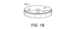
図1Aおよび図1Bを参照すると、本明細書で述べられる技法によってパタン付けされてもよいロータの実施形態が図示されている。図1Aおよび図1Bのロータは、注入器弁アセンブリ内に含まれてもよい。図1Aおよび図1Bの実施例100内に明記された様々な図を有するロータは、その表面に溝112、114、および116を含む。要素110は、ステータに面するロータの表面図を提示する。110のロータは、3つの溝112、114、および116がステータに面する表面上に形成されたディスクとして図示されている。要素115a〜115cは、ロータ内に形成されてもよい3つの通り穴である。通り穴115a〜115cは、ロータを弁アセンブリ内に位置決めするために使用されてもよい。例えば、弁アセンブリ内に含まれ、ステータに面しないロータの表面と接触した別の部品(図示されず)が、3つの通り穴115a〜115cそれぞれに対応する位置を備えた3つの突起部を含んでもよい。
Referring to FIGS. 1A and 1B, an embodiment of a rotor that may be patterned by the techniques described herein is illustrated. The rotor of FIGS. 1A and 1B may be included in an injector valve assembly. The rotor having the various views specified in the
ロータの一実施形態では、ロータは約0.706+/−0.003インチの直径を有してもよい。各溝はほぼ同じ寸法および大きさを有してもよい。例えば、各溝は、幅が0.008+/−0.001インチであってもよく、0.04マイクロリットルの容積を保持してもよい。溝112、114、および116はそれぞれロータの中心から同じ間隔Rを置いて位置付けられ、半径Rを有する円の同じ円周の一部位に沿って延在するように形状化される。この実施例では、上述の円は0.100インチという例示的な直径を有する。各溝は、60度の角度に関連付けられる円周の一部位のまわりに延在するのに充分な長さを有する。各溝は、円周に沿って他の溝から等間隔となるように位置決めされる。要素150は、注入器弁内に含まれる場合のあるような外側金属リング内に含まれるディスクとしての、ロータの異なった図を示す。3つの溝112、114、および116、ならびに通り穴115a〜115cは、例えばドリルまたは他の適切な工具を使用して機械加工するなど、当分野で知られている任意の1つまたは複数の適切な技法を使用して形成されてもよい。
In one embodiment of the rotor, the rotor may have a diameter of about 0.706 +/− 0.003 inches. Each groove may have approximately the same dimensions and size. For example, each groove may be 0.008 +/− 0.001 inch wide and hold a volume of 0.04 microliters. The
図1Aおよび図1Bのロータを備えた注入弁アセンブリ内にステータ(図示されず)が含まれてもよい。当分野で知られているように、また以下により詳しく述べられるように、ステータは、ロータの表面に接触しない第1表面と、図1Aおよび図1Bの実施例100内で示されるような溝が形成されたロータの表面と接触する対向する第2表面とを有してもよい。前述のステータの第1表面は、ステータを通る対応するポート穴を有する、開口部を第2表上に備えた6つのポートなどの、いくつかのポートを含んでもよい。ロータに面するステータの第2表面上に形成されたポート穴の開口部は、図1Aのロータ110内の3つの溝112、114、および116と中心から同じ間隔に位置付けられる。上述のことによって、ステータの第2表面(ロータと接触する)上のポート穴の開口部がロータの溝112、114、および116と位置合わせされた状態になる。
A stator (not shown) may be included in the injection valve assembly with the rotor of FIGS. 1A and 1B. As is known in the art and described in more detail below, the stator has a first surface that does not contact the surface of the rotor, and a groove as shown in the
ロータは、この例示的な弁アセンブリでは3つの溝が形成されたディスクであるが、本明細書で述べられる技法を使用して形成されるロータには、任意の数、形状、および寸法の溝が形成されてもよい。例えば、本明細書で述べられる技法によって製作されるロータの第2実施形態では、ロータは3つの溝を含んでもよく、溝114と116は同じ寸法であってもよく、上述の大きさを有してもよい。第3溝112は溝114、116よりも長い長さを有してもよい。溝112は、60度の角度ではなく、74度の角度に関連付けられた上述の円周の一部位のまわりに延在するのに充分な長さを有してもよい。
The rotor is a disk with three grooves formed in this exemplary valve assembly, but rotors formed using the techniques described herein may have any number, shape, and size of grooves. May be formed. For example, in a second embodiment of a rotor made by the techniques described herein, the rotor may include three grooves, and
Vespel SCP 5000から形成されるロータの実施形態は、例えばVespel SCP 5000の円柱状ロッドから0.141インチなどの所望の厚みのディスク部位を切り取ることによって製作されてもよい。ディスク部位は、当業者に知られている任意の適切な技法を使用して所望の仕様に従ってさらに形状化されてもよい。例えば、溝、通り穴などが、機械加工または当分野で知られている他の適切な技法を使用して製作されてもよい。他の実施例として、参照によって本明細書に組み込まれる、代理人整理番号WCS−004PR/W−541の2008年10月28日に出願された米国仮特許出願第61/108,965号明細書のTECHNIQUES FOR PATTERNING VALVE COMPONENTSで述べられるように、本明細書で述べられるロータの表面上などの溝またはパタンは、圧力を掛けることのみの、または熱と組み合わせた型押し技法を使用して形成されてもよい。さらに、ロータの任意の部位が任意選択で、知られている被覆および適正な技法を使用して必要に応じて被覆されてもよい。Vespel SCP 50094から形成されるロータの実施形態も、上述の方法と類似の方法で製作されてもよい。
An embodiment of a rotor formed from
上述のような実施形態のロータがその中心軸のまわりで回転式に作動する。この作動によって、ステータに面したロータの表面上に位置付けられた溝が動いて、ステータの様々なポートへの様々な流体接続をもたらす。そこで溝は2つのポートの間にチャネルを形成し、そこに流体が流れる。さらに、試料ループに出入りする注入試料の流路を形成することに関連して、第1表面(ロータに面さない)内でステータのポートに管が接続されてもよい。試料は、ポンプなどを使用して圧力を掛けることによって試料ループから押し出されることができる。弁の構成および使用法に依存して、任意のポートが、LCシステム内の流体に対する入口ポートまたは出口ポートとなってもよい。LCシステムの注入器弁では、様々な量の試料を充填し、次いでLCシステムの中に注入するために、ロータは固定ステータに対して様々な位置へと作動されてもよい。LCシステム内の注入器に関連した本明細書に述べられるロータおよび関連付けられる弁は、固定ループ注入器または他のタイプの注入器で使用されてもよいことに留意されたい。本明細書で述べられるロータおよび材料は、注入器に関連して使用されるものとは別の弁に関連して使用されてもよい。 The rotor of the embodiment as described above operates rotationally about its central axis. This action moves the grooves located on the surface of the rotor facing the stator, resulting in various fluid connections to the various ports of the stator. The groove then forms a channel between the two ports, through which the fluid flows. In addition, a tube may be connected to the port of the stator within the first surface (not facing the rotor) in connection with forming a flow path for the injected sample entering and exiting the sample loop. The sample can be pushed out of the sample loop by applying pressure using a pump or the like. Depending on the configuration and usage of the valve, any port may be an inlet or outlet port for fluid in the LC system. In the injector valve of the LC system, the rotor may be actuated to various positions relative to the stationary stator in order to fill various amounts of sample and then inject into the LC system. Note that the rotors and associated valves described herein associated with injectors in an LC system may be used with fixed loop injectors or other types of injectors. The rotors and materials described herein may be used in conjunction with a valve other than that used in conjunction with the injector.
上述のものは、試料が試料ループの中に移送され、試料ループがシステムの流路の一部になるLCシステム内に含まれてもよい、固定ループ注入器としても知られるタイプの注入器の実施例である。例えば、Walters CorporationのACQUITY UPLC(R)システムは固定ループ注入器を使用する。当分野で知られている他のタイプの注入器が、試料が針の中に吸引されてもよく、針がシステムの流路の一部になる直接注入器として特徴付けられることができる。直接注入器では、LCシステムの中への試料の取り込みに関連して試料ループが利用されることはない。例えば、Walters CorporationによるAlliance HPLC(R)システムは、直接注入を使用する。 The above is a type of injector known as a fixed loop injector that may be included in an LC system where the sample is transferred into the sample loop and the sample loop becomes part of the system flow path. This is an example. For example, the Walters Corporation ACQUITY UPLC® system uses a fixed loop injector. Other types of injectors known in the art may be characterized as a direct injector where the sample may be aspirated into the needle and the needle becomes part of the system flow path. In a direct injector, the sample loop is not utilized in connection with sample uptake into the LC system. For example, the Alliance HPLC® system by Walters Corporation uses direct injection.
次に述べられるのは、直接注入器で使用される、ニードルシールであるシール部材の例示的な実施形態である。このような実施形態では、ニードルシールは、Vespel SCP 5000またはSCP 50094の材料などの本明細書で述べられる材料の1つを使用して形成されてもよい。シール部材という用語は、一般的に、固定シールまたは動的シールを形成するのに使用される本明細書で述べられるニードルシールまたはロータなどの部品を指して用いられてもよいことに留意されたい。
Described next is an exemplary embodiment of a seal member that is a needle seal for use with a direct injector. In such embodiments, the needle seal may be formed using one of the materials described herein, such as the
図2Aおよび図2Bを参照すると、本明細書の技法によるLCシステム内の直接注入で使用されるニードルシールと、針と、注入ポートの構成要素との実施例が示されている。実施例180は、ニードルシール184を含む注入ポート181の構成要素を図示する。本明細書の技法および材料によるニードルシールの例示的な実施形態について、以下のパラグラフでより詳しく述べられる。ニードルシール184は、試料をLCシステムの中に取り込む直接注入技法の動作中に動的シールを形成するものとして特徴付けられることができる。直接注入を実施することに関連して、試料が、196によって図示されるような針の中に吸引されてもよい。次いで最初の時点で、針は充分な下向きの力によって垂直方向に開口部182の中へ、通路183の中へ、ニードルシール184内の開口部184aの中へと挿入される。針先端は、ニードルシール184内の開口部184aの中の側壁と接触してシールを形成する。要素190は、181内に含まれるニードルシールの一部位の拡大図である。190にさらに詳しく図示されるように、開口部184aはニードルシールを通る通り穴を形成する。184aの内側壁はテーパ状にされ、一点へと狭窄されて、針先端が184aの中に挿入されると184aの内側壁が狭まるにつれてそれと接触するようになる。シールが形成されるのは、針先端と内側壁の間の前述の接触点においてである。針が挿入される間の最初の時点で、ニードルシールに対する加圧はない。針がニードルシール184の中に一度挿入され、針先端と開口部184aの中のニードルシール側壁表面との間の接触点に適正な量の力が存在すると、流体流れがオンにされ、システムの加圧をもたらす。針先端と184aの内側壁の間の接触点にシールが形成される。すると針を通る流体流れが停止され、ニードルシールおよびシステムはなお加圧された状態となる。次いで第2の時点で、針は上向き垂直方向に183に沿ってニードルシール184から引き出されて、圧力降下を引き起こす。
Referring to FIGS. 2A and 2B, examples of needle seals, needles and injection port components used in direct injection in an LC system according to the techniques herein are shown. Example 180 illustrates the components of
参照によって本明細書に組み込まれる、代理人整理番号W−539/WCS−010PRの2010年1月11日に出願された米国仮特許出願第61/203,902号明細書のINJECTION PORT NEEDLE SUPPORT AND WASHING(「NEEDLE SUPPORT AND WASHINGの特許出願」)などでより詳しく述べられるように、187によって示される材料と、その中に形成される通路183と、任意選択のポート186a、186bと、それらの183への接続部186c、186dは針支持構造体を備えることができる。通路183は、例えば、針196で使用するために0.062+/−0.003インチの範囲内の直径を有してもよい。針支持構造体は、一実施形態で使用される場合のある所望の針の直径および/または長さを収容するために他の適切な大きさを有してもよいことに留意されたい。
INJECTION PORT NEEDLE SUPPORT AND of US Provisional Patent Application No. 61 / 203,902, filed on Jan. 11, 2010, with reference number W-539 / WCS-010PR, incorporated herein by reference. As described in more detail in WASHING (“NEEDLE SUPPORT AND WASHING patent application”) and the like, the material indicated by 187, the
一実施形態では、針先端が、第1点196aで0.040+/−0.001インチの外径(OD)を有するようにテーパ状の先端を有する針196が使用されてもよい。針は、例えばステンレススチールであってもよい。針先端は第一点196aから第2点196bへテーパ状にされ、狭窄されてもよく、そこで針先端の外側表面がニードルシールの内側壁と接触する。一実施形態では、第2点のODは0.013+/−0.001インチであってもよい。針先端は196で図示されるように13度の角度でテーパ状にされてもよい。要素190は、上述の針196で使用されることができるニードルシール184の一実施形態のいくつかの例示的な測定値を示す。ニードルシールの開口部184aは、図示されるように20度の角度に従って点190aへテーパ状にすることによって狭窄されてもよい。点190aから点190bへ、開口部184aは0.007インチという比較的均一または一定の直径を有してもよい。開口部184aは、針が第1表面または上表面で進入するように、ニードルシール184を通る通り穴を形成してもよい。点190bは上述の上表面に対向するニードルシールの底表面にあってもよい。
In one embodiment, a
さらに図示されているのはポート186aおよび186bであり、それらを通って様々な溶剤または他の流体が181を流入出することができる。要素185は、ポートと、関連付けられる導管または配管とであってもよく、試料がそれを通って上述のように一度注入されたところから流れ出す。要素185は直接または間接的にLCカラムに接続されてもよい。ニードルシールと挿入された針とに関連して掛けられ、使用される力の量は、当分野で知られている多様な技法のいずれかを使用して決定されてもよい。例えば、本明細書で述べられる直接注入に関連した動的シールを形成するニードルシールの実施形態は、例えば、参照によって本明細書に組み込まれる代理人整理番号WCS−009PR/W−540の2010年1月11日に出願された米国仮特許出願第61/293,889号明細書のNEEDLE SEAL FORCE SENSOR(「NEEDLE SEAL FORCE SENSORの特許出願」)で述べられる技法によって使用されてもよい。図2Bで示される一部の構成要素、バネ188aおよび荷重セル188bなどは、任意選択でNEEDLE SEAL FORCE SENSORの特許出願で述べられる力センサを使用する実施形態に含まれてもよい。
Also illustrated are
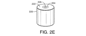
図2C〜図2Iを参照すると、本明細書で述べられる技法によって製作されてもよいニードルシールの第1実施形態の実施例が示されている。実施例200は、第1内側部位またはコア224と第2外側部位またはコア222とを有するニードルシール220を図示する。第1内側部位224内に形成されているのは、開口部226(図2Aおよび図2B内では184aと付されている)であり、この中に針が直接試料注入のために挿入される。この実施形態では、内側部位224はVespel SCP 5000で製作されてもよい。内側部位224は第2外側部位222で包み込まれてもよい。第2外側部位222は、例えば18K金または12K金あるいはステンレススチールで製作されてもよい。要素210は、ニードルシール220を上から見た図である。210のニードルシールの上部の直径は0.215インチであってもよい。
With reference to FIGS. 2C-2I, an example of a first embodiment of a needle seal that may be fabricated by the techniques described herein is shown. Example 200 illustrates a
要素230は、210の線A−Aに沿ったニードルシールの側面図である。実施例230では、ニードルシールの外側円筒壁の長さ230aは、0.235+/0.003インチであってもよい。上述のように、開口部232は、第1部位230cと第2部位230bを有するニードルシールを通る通り穴を形成してもよい。部位230bは非テーパ状であってもよく、0.093インチの長さを有してもよい。開口部234は、0.007+0.001/−002インチの直径を有してもよい。230の様々な態様の追加の詳細部が、後続図に、詳細部Bの236、詳細部Cの238、詳細部Fの240、および詳細部Gの242と示されて提示されている。図2Fの要素236は追加の詳細部Bを示し、角表面が、ここに示される45度の角度で形成されて、表面2Fで長さが0.005+/−0.002インチとなってもよい。
図2G〜図2Iを参照すると、図2C〜2Fに示された本明細書で述べられる技法によるニードルシールの実施形態の様々な態様の追加の詳細部が示されている。要素238は、試料のLCシステムの中への取り込みに関連して針が挿入されるニードルシールの開口部および通り穴の追加の詳細部Cを提示する。部位252は、均一な直径を有する第1部位252aと狭窄されたテーパ状部位である第2部位252bとを含む。第1部位252aは0.065インチの長さを有してもよく、第2部位252bは0.077インチの長さを有してもよい。針が最初に挿入されるニードルシールの表面の開口部232は、0.0410+0.0005/−0.0010インチの直径を有してもよい。第2のテーパ状部位は、図示されるように25度の角度を有する円錐状セクションを形成してもよい。要素240は追加の詳細部Fを提示し、ここに示される45度の角度で形成された角表面の長さが表面2Hで測定して0.013+0.010/−0.005インチであってもよいことを示す。要素242は追加の詳細部Gを提示し、シールの底表面の通り穴が図示されるように82度の角度で外向きにテーパ状となってもよいことを示す。底表面の点242bで測定して、通り穴は0.015+/−0.003インチの直径を有してもよい。242では、通り穴は点242aで上述のように0.007インチなどの第一直径を有する。第一直径は、表面の点242bで測定して0.015+/−0.003インチの第2直径に対して増大してゆき、それによって開口部に外向きテーパ状または円錐状のセクションを形成する。
Referring to FIGS. 2G-2I, additional details of various aspects of the needle seal embodiments according to the techniques described herein shown in FIGS. 2C-2F are shown.
図2C〜図2Iに関連して図示されたニードルシールの実施形態は、Vespel SCP 5000の内側部位またはコア(図2Eの224など)を形成することによって形成されてもよい。ロータと共に上述された一実施形態では、Vespel SCP 5000の材料は円柱状ロッドから得られてもよく、そこからディスク部位が所望の厚みに切り取られることができる。次いでディスク部位はさらに機械加工されて、針が中に挿入される開口部を備えた通り穴を含む所望の形状および大きさを得ることができる。金またはステンレススチールから製作されてもよいなどの外側部位またはコア(図2Eの222など)は、所望の形状および大きさに形成されてもよく、Vespel SCP 5000の内側部位またはコアの挿入を収容するように適正な寸法の通り穴を含んでもよい。Vespel SCP 5000の内側部位またはコアは、内側部位が、外側部位の中への挿入によってプレス嵌めされることができるように変形可能である。
The needle seal embodiment illustrated in connection with FIGS. 2C-2I may be formed by forming the inner portion or core of the Vespel SCP 5000 (such as 224 in FIG. 2E). In one embodiment described above with the rotor, the
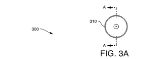
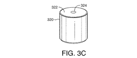
図3A〜3Gを参照すると、本明細書で述べられる技法によって製作されてもよいニードルシールの第2実施形態の実施例が示されている。実施例300は、部位またはコア322を有するニードルシール320を図示する。部位322内に形成されるのは、直接試料注入のために針が中に挿入される開口部326(図2Aおよび図2Bでは184aと付されている)である。この実施例では、部位322はVespel SCP 5000で製作されてもよい。要素310はニードルシール220を上から見た図である。310のニードルシールの上部の直径は、0.215+0.0005/−0.0010インチであってもよい。
Referring to FIGS. 3A-3G, an example of a second embodiment of a needle seal that may be fabricated by the techniques described herein is shown. Example 300 illustrates a
要素330は310の線A−Aに沿ったニードルシールの側面図である。実施例330では、ニードルシールの外側円筒壁の長さ330aは0.235+/0.0003インチであってもよい。上述のように、開口部332は、ニードルシールを通るように、第1部位330cと第2部位330bを有する通り穴を形成してもよい。部位330bは非テーパ状であってもよく、0.93インチの長さを有してもよい。開口部334は0.007+0.001/−002インチの直径を有してもよい。330の様々な態様の追加の詳細部が、後続図に、詳細部Bの336、詳細部Cの338、詳細部Dの340、および詳細部Eの242と示されて提示されている。図3Dの要素338は追加の詳細部Cを示し、ここに示される45度の角度で形成された角表面3Dは0.005+/−0.002インチであってもよいことを示す。
図3E〜図3Gを参照すると、図3A〜図3Dに図示される本明細書の技法によるニードルシールの実施形態の様々な態様の追加の詳細部が示されている。要素336は、LCシステムの中への試料の取り込みに関連して針が挿入されるニードルシールの開口部および通り穴の追加の詳細部Dを提示する。部位352は、均一な直径を有する第1部位352aと狭窄テーパ状部位である第2部位352bとを含む。第1部位352aは0.065インチの長さを有してもよく、第2部位352bは0.077インチの長さを有してもよい。針が最初に挿入されるニードルシールの表面の開口部332は、0.0410+/−0.0010インチを有してもよい。第2テーパ状部位は図示されるように25度の角度を形成してもよい。要素342は追加の詳細部Eを提示し、ここに示される45度の角度で形成される角表面3Fが0.013+0.010/−0.005インチでもよいことを示す。要素340は追加の詳細部Dを提示し、シールの底表面の通り穴が図示されるように90度の角度で外向きにテーパ状となってもよいことを示す。点342bの底表面で測定されるように、通り穴は0.015+/−0.003インチの直径を有してもよい。340では、通り穴は上述のように0.007インチなどの第1直径を点342aで有し、第1直径は、点342bの表面で測定して0.015+/−0.003インチの第2直径に対して増大してゆき、それによって外向きにテーパ状または円錐状の開口部を形成する。
Referring to FIGS. 3E-3G, additional details of various aspects of a needle seal embodiment according to the techniques herein illustrated in FIGS. 3A-3D are shown.
図3A〜図3Gに関連して図示されるニードルシールの実施形態は、Vespel SCP 5000の部位またはコア(図3Cの322など)を形成することによって製作されてもよい。ロータと共に上述された一実施形態では、Vespel SCP 5000の材料は、ディスク部位が所望の厚みで切り取られることができる円柱状ロッドから得られてもよい。次いでディスク部位はさらに機械加工されて、針が中に挿入される開口部を備えた通り穴を含む所望の形状および大きさを得ることができる。図3A〜図3Gのこの第2実施形態では、ニードルシール全体がVespel SCP 5000から形成されてもよい。図3A〜図3Gの上述の実施形態は、ニードルシールの第1実施形態(図2C〜図2I)とは対照的である。第1実施形態(図2C〜図2I)では、Vespel SCP 5000が内側部位を形成し、これが、金またはステンレスで製作されるなどの外側部位内に包み込まれる。
The needle seal embodiment illustrated in connection with FIGS. 3A-3G may be fabricated by forming a
図3H〜図3Rを参照すると、本明細書で述べられる技法によって製作されてもよいニードルシールの第3実施形態の実施例が示されている。実施例1000は、第1部品1002と第2部品1004を有するニードルシール1001を図示する。第2部品1004内に形成されるのは、直接試料注入のために針が中に挿入される開口部1006である。この実施形態では、第2部品1004はVespel SCP 5000で製作されてもよい。第1部品1002は、例えばタイプ316ステンレススチールなどのステンレススチールで製作されてもよい。第1部品1002はむしろ一般的に、第2部品1004を備える材料よりも機械的強度が高いと特徴付けられることができる1つまたは複数の他の材料で製作されてもよい。例えば、第1部品1002は、第1材料(およびその結果もたらされる第1部品1002)が第2部品1004よりも大きな強度を有することを示す1つまたは複数の機械的特性を有する第1材料で製作されてもよい。
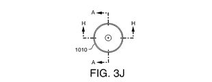
With reference to FIGS. 3H-3R, there is shown an example of a third embodiment of a needle seal that may be fabricated by the techniques described herein. Example 1000 illustrates a
第2部品1004は、1001の図で見られる上部位1022aと、1001の組み合わせられた図では見られない底部位1022b(点線によって示される)とを含んでもよい。上部位1022aは1001の図では円形またはディスク形状を有する。点線は、底部位1022bによって形成される外形線を図示する。底部位1022bは第1部品1002の側壁の中に包み込まれる。第1部品1002は、ニードルシールが組み合わせられるときに底部位1022bが中に挿入される穴または開口部(図示されず)を有する。
The
1022によって示されるように、第2部品1004は、側方から見るとT字形状の輪郭を有してもよく、0.235インチの長さL1を有してもよい。底部位1022bの直径D1は、0.1005インチから0.1010インチまでの端値を含む範囲内の寸法を有してもよい。上部位1022aの長さまたは厚みL2は0.055インチであってもよい。要素1010は、上から見た1001のニードルシールを示す図であり、上部位1022aの直径は、0.225から0.226インチまでの端値を含む範囲内であってもよい。
As indicated by 1022, the
要素1021は、1010の線H−Hに沿ったニードルシールの側面図であり、1001の組み合わせられたニードルシール内で底部位1022bが中に挿入される第1部品1002に関する追加の詳細部を提示する。第1部品1002の形状は、円筒状であってもよく、底部位1022bが中に挿入される穴または開口部1021aが通るように形成される側壁1002aを有する。穴1021aは0.1000インチから0.1004インチまでの端値を含む範囲内の直径を有してもよい。第1部品1002の側壁1002aは0.180インチの長さL3を有してもよい。図3Lの要素1020は追加の詳細部Jを図示し、角表面3Lがここに示される45度の角度で形成されて、表面の長さが0.010+/−0.005インチとなってもよいことを示す。
図3M〜図3Oを参照すると、本明細書の技法によるニードルシールの第3実施形態の様々な態様の追加の詳細図が示されている。要素1110は、1010の線A−Aに沿ったニードルシールの側面図である。実施例1110では、ニードルシールの外側円筒状壁の長さ1116は(1001内に示されるように組み合わされると)0.235+/−0.003インチであってもよい。第2部品1004には、開口部1006と1112を両端部に備えた穴または通路1120がそれを通るように形成されている。第2部品1004内の穴1120は、第1部位1119(内向きに狭窄され、またはテーパ状である)と第2部位1118とを有するように形成されてもよい。部位1118は0.156インチの長さを有してもよい。開口部1122は0.007+0.001/−002インチの直径を有してもよい。第1部品の底部(開口部1122を有する端部)の直径1114は、0.215から0.216インチまでの端値を含む範囲内であってもよい。1110の様々な態様の追加の詳細部が後続図に、詳細部Bの1104、詳細部Cの1102、詳細部Fの1108、詳細部Gの1124、および詳細部Kの1106と示されて提示されている。
Referring to FIGS. 3M-3O, additional details of various aspects of a third embodiment of a needle seal according to the techniques herein are shown.
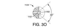
要素1102は、LCシステムの中への試料の取り込みに関連して針が挿入されるニードルシールの開口部1106の追加の詳細部Cを提示する。部位1119は、0.079インチの長さを有する狭窄されたテーパ状の部位である。針が最初に挿入されるニードルシールの表面の開口部1006は、0.042+/−0.002インチの直径を有してもよい。部位1119は、図示されるように25度の角度を有する円錐状セクションを形成してもよい。ニードルシールが組み合わされた後に(図3Iの1001などのように)、穴1120(およびその両端部の開口部)が機械加工されてもよい。要素1124は追加の詳細部Gを提示し、シールの底表面に開口部1122(針が挿入される1120の対向端部)を有する通り穴1120が、図示されるように90度の角度で外向きにテーパ状になってもよいことを示す。底表面の1160で測定して、通り穴は0.013+0.002/−0.001インチの直径を有してもよい。1124で、通り穴の図示される端部の開口部は、点1161で上述のように0.007+0.001/−002などの第1直径を有する。第1直径は、表面の点1160で測定して0.013+0.002/−0.001インチの第2直径に対して増大してゆき、それによって外向きのテーパ状または円錐状のセクションを形成する。
図3P〜図3Rを参照すると、本明細書の技法によるニードルシールの第3実施形態の様々な態様の追加の詳細部が示されている。図3P〜図3Rの図1200は、図3Mの詳細部Bの1104、詳細部Fの1108、および詳細部Kの1106についてさらに述べる。要素1106は追加の詳細部Kを提示し、図示される45度の角度で形成される角表面の長さは表面3Qで測定して0.005インチであってもよいことを示す。要素1108は追加の詳細図Fを提示し、ここに示される45度の角度で形成される角表面の長さが表面3Pで測定して0.013+0.010/−0.005インチであってもよいことを示す。図3Rの要素1104は追加の詳細部Bを図示し、角表面がここに示される45度の角度で形成され、その長さが表面3Rで0.005+/−0.002インチであってもよいことを示す。
With reference to FIGS. 3P-3R, additional details of various aspects of a third embodiment of a needle seal according to the techniques herein are shown.
図3H〜図3Rに関連して図示される第3のニードルシール実施形態は、Vespel SCP 5000のt字形状の第2部品(図31の1004など)を形成することによって製作されてもよい。上述のように、Vespel SCP 5000の材料は、ディスク部位が所望の厚みで切り取られることができる円柱状ロッドから得られてもよい。次いでディスク部位はさらに機械加工されて、針が中に挿入される開口部を備えた通り穴を含む所望の形状および大きさを得る。ステンレススチールなどで製作されてもよい第1部品(図31の1002など)は所望の形状および大きさに形成されてもよく、Vespel SCP 5000の第2部品の底部位の挿入を収容するように適正な寸法の通り穴を含んでもよい。Vespel SCP 5000で製作された1004の底部位1022bは、上述のように 第1部位1002の通り穴の中への挿入によってプレス嵌めされることができるように変形可能である。図3Mの要素1110を参照して、第2部品の底部位が第1部品の中にプレス嵌めされた後、1111によって示される底表面同士は0.0002インチ内で同一平面上であるように機械加工されてもよいことに留意されたい。
The third needle seal embodiment illustrated in connection with FIGS. 3H-3R may be fabricated by forming a second T-shaped piece of Vespel SCP 5000 (such as 1004 in FIG. 31). As mentioned above, the
戻って図2を参照して、要素183は、針が中に挿入される通路または導管を指し、材料187、例えば、ステンレススチールあるいは当分野で知られている様々な異なった適切なPEEK(ポリエーテルエーテルケトン)材料の1つによって取り囲まれてもよいことに留意されたい。例えば、図2C〜図2Fのニードルシールを使用するとき、実施形態によってはステンレススチールから187を形成してもよい。図3A〜図3Dまたは図3H〜図3Lのニードルシールを使用するとき、実施形態によってはステンレススチールまたはPEEK材料から187を形成してもよい。図3Iの要素1004は、組み合わせ時に、要素1004が機械的組み合わせによる圧力を受けてもその形状を保持するように、充分な直径と周囲材料187との充分な接触面積とを有するべきであることに留意されたい。要素189aはシールを保持する構成要素であってもよい。要素189bはスペーサであってもよい。要素189cはバネ支持体またはカップであってもよい。
Referring back to FIG. 2,
図2Aおよび図2Bの注入ポートの構成要素はハウジングの中に含まれてもよいことに留意されたい。図2Aおよび図2Bに図示された構成要素は任意の適切な材料で製作され、当分野で知られている任意の適切な手段および技法を使用して製造されてもよい。例えば、上述のように、針支持構造体材料187、ならびにポート186aおよび186cを183に接続する接続部はPEEK材料で製作されてもよい。ハウジングはアルミニウムで製作されてもよい。バネ188aと、185に関連して使用される配管と、189a、189b、および189cによって表わされる構成要素とはステンレススチールから製作されてもよい。
Note that the components of the injection port of FIGS. 2A and 2B may be included in the housing. The components illustrated in FIGS. 2A and 2B may be made of any suitable material and manufactured using any suitable means and techniques known in the art. For example, as described above, the needle
図2Aおよび図2Bに関連して図示されるように、ニードルシールの表面は通路183と接触し、その間に実質的に流体密の接続が存在する。同様に、針の洗浄のための洗浄液の経路内に含まれる接続部186cと183の間、186dと183の間にも実質的に流体密の接続が存在してもよい。当業者には言うまでもなく、ここでは明確に記載されていないが、試料、洗浄液などの望ましくない漏れを起こさないように、図2Aおよび図2B内に示され、述べられる他の構成要素同士の間、また本明細書の他の構成要素同士の間の接続も流体密であると特徴付けられてもよい。
As illustrated in connection with FIGS. 2A and 2B, the surface of the needle seal contacts the
ニードルシールは、様々な形状で、本明細書で述べられるものとは異なる封入部を使用して形成されてもよい。本明細書の技法によるニードルシールの実施形態は、針先端と接触してシールを形成する密閉表面で、Vespel SCP 5000またはVespel SCP 50094の材料を使用して形成されてもよい。このようなニードルシールの実施形態は、Vespel SCP 5000またはVespel SCP 50094(図3A〜図3Gなど)のみによって、あるいは針先端と接触するニードルシールの表面がVespel SCP 5000またはVespel SCP 50094から形成される限り、他の適切な材料から形成された他の部位と組み合わせて形成されてもよい。より一般的に、本明細書の技法によるニードルシールまたはロータなどのシール部材の実施形態は、少なくとも密閉表面(固定シールまたは動的シールが形成される)がVespel SCP 5000またはVespel SCP 50094の材料で製作されてもよいことに留意されたい。
The needle seal may be formed in a variety of shapes and using different enclosures than those described herein. Embodiments of needle seals according to the techniques herein may be formed using a
本明細書では動的シールの特定の実施例が提示されるが、Vespel SCP 5000および/またはVespel SCP 50094(あるいは他の商品名および/または販売元を有してもよい類似のポリマー)は、HPLCまたはUPLCシステムなどのLCシステムに関連して使用されてもよい他のタイプの固定シールおよび/または動的シールを形成するのに使用されてもよいことに留意されたい。例えば、LCシステムは、固定シールまたは動的シールが形成される表面で、Vespel SCP 5000またはVespel SCP 50094から製作されたニードシール、チューブシール、フェルール、ガスケット(例えば、チェク弁ガスケット)などの1つまたは複数を含んでもよい。
Although specific examples of dynamic seals are presented herein,
次に述べられるのは、Dupontによって提供されるVespel SCP 5000およびVespel SCP 50094の他の様々な特徴についてである。他の材料が、Vespel SCP 5000およびVespel SCP 50094の特性および特徴に従ったものを有することができる場合には、そのような材料が他の販売元によって供給され、かつ/または本明細書で述べられる以外の商品名を使用して参照されてもよいことに留意されたい。そのような材料は、固定シールまたは動的シールを表面が形成する部品またはシール部材の実施形態で使用するのにも適切である。Vespel SCP 5000およびVespel SCP 50094などの材料は、動的シールまたは固定シールを形成するシール部材で使用するのに望ましい化学的、機械的、および他の特性を有する。
The following is about various other features of
図4を参照すると、本明細書の技法による実施形態で使用されてもよいVespel SCP 5000の応力−歪み曲線のグラフが示されている。図4に関して、応力とは、掛けられた力を横断面積によって除したものとして定義されることができ、歪みは、試料の単位長さあたりの伸長として定義されることができる。図4に関連した臨界点は、図示された曲線の直線部位に沿った最大応力である降伏点として特徴付けられてもよいことに留意されたい。全ての図示された曲線について、これは約30,000psiであり、このことは、材料が潜在的に約30,000psiのこの最大値までの流体圧力で性能を発揮することが可能であることを示唆する。図4の曲線を作成することに関連して利用される標準試験法は、標準試験法ASTM D695である。
Referring to FIG. 4, a graph of the stress-strain curve of
図4は、Vespel SCP 5000(Vespel SCP 5000 ISOとも呼ばれる)の平衡圧縮形状または平衡成形形状を特徴とすることに留意されたい。
It should be noted that FIG. 4 features a balanced compression or molded shape of Vespel SCP 5000 (also referred to as
図5Aおよび図5Bを参照すると、本明細書の技法による実施形態で使用されてもよいVespel SCP 5000(Vespel SCP 5000 ISOまたはSCP 5000 ISOとも呼ばれる)の平衡圧縮形状または平衡成形形状を特徴付ける一部の特性が示されている。これらの特性は、本明細書で述べられるVespel SCP 5000の円柱形状のロッドから機械加工されたロータおよびニードルシールなどの部品に典型的なものの例である。図5Aには、様々な機械的特性が示されている。図5Bでは、様々な熱的特性、電気的特性、摩耗性状、および他の特性が示されている。
Referring to FIGS. 5A and 5B, a portion characterizing a balanced compression or balanced molded shape of a Vespel SCP 5000 (also referred to as
以下のパラグラフでは、図5c〜図5Iと図6A〜図6Fが本明細書の技法による実施形態で使用されてもよいVespel SCP 5000 ISOの他の特性を明記する。
In the following paragraphs, FIGS. 5c-5I and FIGS. 6A-6F specify other characteristics of the
図5Cを参照すると、SP−1との関係におけるVespel SCP 5000 ISOの引張強度のグラフが示されている。室温で、SCP 5000は、SP−1の約2倍の強度と、それと同様の伸長率を示す。摂氏260度で、SCP5000は約50%分大きな強度とより大きな伸長率の特徴を呈示する。
Referring to FIG. 5C, a graph of the tensile strength of
図5Dを参照すると、圧縮下のSCP 5000 ISO およびSP−1の応力−歪み曲線のグラフが示されている。図5Dに示されるように、SCP5000は、室温でも高温でもSP−1よりも大きな圧縮強度を呈示する。
Referring to FIG. 5D, a graph of the stress-strain curve for
図5Cおよび図5DはSCP 5000 ISOの物理的特性を特徴付ける。SPC500は融解せず、摂氏330度のガラス転位温度を有することに留意されたい。
Figures 5C and 5D characterize the physical properties of
図5Eを参照すると、SP−1との関係におけるSCP 5000 ISOの熱的特性のグラフが示されている。図5Eは、高温度で、初期引張強度の50%分までの低下を時間の観点で見た、SP−1ポリアミドと比較したSP5000の特徴を示す。例えば、SP−1は、摂氏370度に連続100時間空気に晒された後、その初期強度の半分を保持する。それとは対照的に、SCP500は、同じ条件下で約550時間持続した後にその初期強度が50%分低下する。少なくとも摂氏340度までの温度では、SCPの部品は、窒素または真空などの不活性の環境では、時間経過による特性の損失をほとんど伴わずに性能を発揮する。図5Eのグラフはむしろ一般的な指針であり、SCP5000で製作された部品の実際の有用な耐用期間はより長くなる場合があることに留意されたい。これは、部品が遭遇する温度が連続的であるよりむしろ間欠的である場合があるということと、部品が、高温の用途で完全に空気に晒されるよりはむしろハウジングによって少なくとも部分的に被覆される場合があるということとによる。
Referring to FIG. 5E, a graph of the thermal properties of
以下の図5F、図5G、および図5Hは、本明細書の技法による実施形態で使用されてもよいSCP 5000 ISOの電気的特性を示す。
FIGS. 5F, 5G, and 5H below illustrate the electrical characteristics of the
図5Fを参照すると、SP−1と比較した、SCP 5000 ISOの温度および周波数の関数としての誘電定数のグラフが示されている。図示されるように、SCP5000は、広範な温度および周波数の範囲にわたってより安定した誘電定数を呈示する。
Referring to FIG. 5F, there is shown a graph of dielectric constant as a function of temperature and frequency for
図5Gを参照すると、SP−1と比較したSCP 5000 ISOの散逸率のグラフが示されている。
Referring to FIG. 5G, a graph of the dissipation factor of
図5Hを参照すると、SP−1と比較したSCP 5000 ISOの絶縁耐力のグラフが示されている。試験結果は、1.0mmの厚さの試料について、SP−1およびSCP 5000は、広範な温度範囲にわたって安定した絶縁耐力を呈示するが、SCP5000がSP−1よりも僅かに大きな絶縁耐力を呈示することを示している。図5Iに同様に含まれている表572は、SP−1と比較したSCP5000の表面抵抗率および体積抵抗率を示す。
Referring to FIG. 5H, a graph of the dielectric strength of
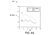
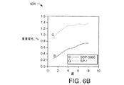
以下の図6Aおよび図6Bは、本明細書の技法による実施形態で使用されてもよいSCP5000 ISOの寸法安定性を示す。 FIGS. 6A and 6B below illustrate the dimensional stability of the SCP5000 ISO that may be used in embodiments according to the techniques herein.
図6Aを参照すると、制御された環境チャンバ内で華氏100度と相対湿度90%とに晒されたときの、SP−1と比較したSCP5000の寸法安定性のグラフが示されている。 Referring to FIG. 6A, a graph of the dimensional stability of SCP5000 compared to SP-1 when exposed to 100 degrees Fahrenheit and 90% relative humidity in a controlled environmental chamber is shown.
図6Bを参照すると、図6Aで述べられた制御された環境条件下でのSP−1と比較したSCP5000の被検査物の重量増加のグラフが示されている。図6Bは、時間経過による試料の重量パーセントの増加を示し、SCP5000はSP−1と比較して吸湿量が約50%少ない。
Referring to FIG. 6B, there is shown a graph of
ポリアミドと同様に、SCP5000およびSP−1は加水分解を受け、摂氏100度を超える温度の水また蒸気内で厳しいクラッキングが起こる場合があることに留意されたい。 It should be noted that, like polyamides, SCP5000 and SP-1 are subject to hydrolysis and severe cracking may occur in water or steam at temperatures above 100 degrees Celsius.
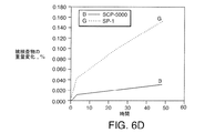
以下の図6C、図6D、および図6Eは、無水アンモニア蒸気への暴露の影響に関するSP−1と比較したSCP 5000 ISOの特性を示すグラフである。40時間を超える暴露の後、SCP5000の被検査物は厚みの無変化(図6C)と、最小限の重量増加(図6D)とを呈示した。さらに、SCP‐5000はその初期強度のほぼ全てを保持する(図6E)。
Figures 6C, 6D, and 6E below are graphs showing the properties of
有機溶剤は、一般的にポリイミド部品の機械的および寸法安定性に対して最小限の影響しかもたらさないことに留意されたい。ぺルクロロエチレンおよびトリクロロエチレンなどの塩素化溶剤およびフッ化溶剤が表面洗浄に推奨される。トルエンおよびケロセンなどの炭化水素溶剤は、ポリイミド材料に対して実質的に影響をもたらさない。m−クレゾールおよびニトロベンゼンなどの官能基を含む一部の溶剤は、高温で、その機械的強度を実質的に低下させずにポリアミドの膨張を引き起こすことが可能である。 Note that organic solvents generally have minimal impact on the mechanical and dimensional stability of polyimide parts. Chlorinated and fluorinated solvents such as perchlorethylene and trichlorethylene are recommended for surface cleaning. Hydrocarbon solvents such as toluene and kerosene have virtually no effect on the polyimide material. Some solvents containing functional groups such as m-cresol and nitrobenzene can cause the polyamide to swell at high temperatures without substantially reducing its mechanical strength.
濃縮鉱酸は、比較的短時間でポリイミド部品の激しい脆化を引き起こす場合がある。一般的に、希酸溶液と酸性pHを有する無機塩類の水性溶液とはポリイミドに対して水とほぼ同じ影響をもたらす。一般的に、ポリイミド樹脂はアルカリ性の攻撃に対して感受性が高い。塩基水溶液はポリアミド類を攻撃して、特性の急速な劣化をもたらす。したがって、塩水溶液を含むpH10以上を有する塩基溶液は、SCP5000の部品での使用は好まれない場合がある。 Concentrated mineral acid can cause severe embrittlement of polyimide parts in a relatively short time. In general, a dilute acid solution and an aqueous solution of inorganic salts having an acidic pH have about the same effect on polyimide as water. In general, polyimide resins are highly sensitive to alkaline attacks. Aqueous base solutions attack polyamides and cause rapid degradation of properties. Accordingly, a base solution having a pH of 10 or more, including an aqueous salt solution, may not be preferred for use with SCP5000 parts.
図6Fおよび図6Gを参照すると、表内にSCP 5000 ISOで形成された平衡圧縮形状に典型的な追加の特性が示される。
Referring to FIGS. 6F and 6G, the additional characteristics typical of the equilibrium compression shape formed with
次に述べられ、示されるのは、Vespel SCP 50094の特性についてである。
Next described and shown is about the properties of
図7A〜図7Dを参照すると、表内に、Dupont(TM)によって販売されるVespel SCP 50094から製作された直接成形(DF)部品の特性が示されている。当業者には言うまでもなく、直接成形とは、機械加工に対立するものとして部品が作り出される別の方法を意味する。当分野で知られているように、直接成形とは、熱硬化材料で近似値正味形状部品を形成することを意味する。図7A〜図7Bは、Vespel SCP 50094で製作されたポリイミドDF部品の機械的特性を示す。図7C〜図7Dは、Vespel SCP 50094で製作されたポリイミドDF部品の熱的特性、電気的特性、および摩耗性状を示す。
Referring to FIGS. 7A-7D, the properties of direct molded (DF) parts made from
図7E〜図7Fを参照すると、Vespel SCP 50094で製作されたDF部品の追加の特性のグラフが示されている。図7Eは、圧縮クリープを示す第1グラフ722を含み、図7Fは熱伝導性を示す第2グラフ724を含む。
Referring to FIGS. 7E-7F, a graph of additional characteristics of a DF part made with
図7G、図7H、および図7Iを参照すると、Vespel SCP 50094(Vespel SCP 50094 ISO)の平衡圧縮形状または平衡成形形状を特徴付けるVespel SCP 50094から製作された部品の特性が表に示されている。図7G〜図7Hは、平衡圧縮または平衡成形されたVespel SCP 50094(Vespel SCP 50094 ISO)から製作された部品の機械的特性を示す。図7Iは、平衡圧縮または平衡成形されたVespel SCP 50094(Vespel SCP 50094 ISO)から製作された部品の熱的特性、摩耗性状、および他の特性を示す。
Referring to FIGS. 7G, 7H, and 7I, the properties of parts made from
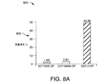
図8A〜図8Cを参照すると、他の材料と比較したSCP 50094の様々な特性が示されている。要素802は、他の材料と比較したSCP 50094 DFの熱酸化安定性のグラフであり、ここでは試料は、摂氏371度、4.76atm(70psia)の条件に100時間晒された。このような条件下で、SCP 50094から製作された試料は2.81%の重量損失を生じた。要素804は、他の材料と比較したSCP 50094 DFのヤング係数および曲げ弾性率(804aおよび804bで示される)のグラフである。要素806は、他の材料と比較したSCP 50094の熱膨張の係数(806aで示される)のグラフである。
Referring to FIGS. 8A-8C, various properties of
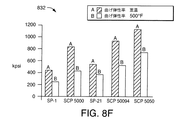
図8D〜図8Fを参照すると、平衡形状グレード(ISO)の他のVespel材料と比較したVespel SCP 5000およびSCP 50094の追加の様々な特性が示されている。図820は、表822内の例示的な機械的特性、摩耗性状、および他の特性を含む。要素826は、SCP 5000の特性を示し、要素828はSCP 50094の特性を示す。同様に図8Eの引張強度のグラフ表示830と図8Fの曲げ弾性率のグラフ表示832とも含まれる。ここでAは室温(RT)における材料を示し、Bは華氏500度における材料を示す。
Referring to FIGS. 8D-8F, various additional properties of
図9A、図9B、および図9Cを参照すると、発明者らによって試験された、Vespel SCP 5000との使用に適応性があると判定された溶剤の表が示されている。試験用試料は、長さが0.40インチ、直径が0.25インチの円柱である(試験ガイドラインに示される通り)。試験用試料は4週間観察され、ここに示される溶剤を含む試験容器内に配置された。試験は、溶剤または材料に視覚的変化のないことを示した。試料が取り除かれたとき、質量または形状に有意な変化はなかった。
Referring to FIGS. 9A, 9B, and 9C, a table of solvents tested by the inventors and determined to be adaptable for use with
Vespel SCP 5000および/またはVespel SCP 50094などの材料は、LCシステムならびに他の用途に関連してロータまたはニードルシールなどのシール部材を形成することに関連して使用するのに望ましい、本明細書で述べられる通りの特性を有する。類似のシール用途で使用される他のポリマーと比較して優れた強度および摩耗性、ならびに高度の化学的適合性などの特徴が、例えば本明細書で述べられるUPLCシステムまたはHPLCシステムなどの様々な異なった用途の固定シール部材および/または動的シール部材を形成するための材料に極めて望ましい場合のあるものの一部である。材料の選択に関連して考慮される他の特質としては、多孔性処理の問題(シールが形成される表面の状態など)などに関連して充分なシールを形成する材料の能力、あるいは炭素、ガラス、または当業者に知られている他の適切な補強材などによって材料が補強される能力に関連する場合がある。
Materials such as
ここに詳しく示され、述べられた好ましい実施形態に関連して本発明が以上に開示されたが、当業者にはそれらの修正形態および改良形態が容易に明らかとなろう。したがって、本発明の精神および範囲は以下の請求項によってのみ限定されるべきである。 Although the present invention has been disclosed above in connection with the preferred embodiments shown and described in detail herein, those modifications and improvements will be readily apparent to those skilled in the art. Accordingly, the spirit and scope of the present invention should be limited only by the following claims.
Claims (37)
Vespel SCP 5000またはVespel SCP 50094の一方である材料の一部位を提供するステップと、
前記部品を作り出すために前記部位を処理するステップであって、前記部品はその表面に固定シールまたは動的シールを形成するのに使用されるステップと、を備える方法。 A method of manufacturing a component, comprising:
Providing a portion of material that is one of Vespel SCP 5000 or Vespel SCP 50094;
Treating the site to create the part, wherein the part is used to form a fixed or dynamic seal on a surface thereof.
ディスク様形状を有する、Vespel SCP 5000またはVespel SCP50094の一方である材料の一部位を提供するステップと、
部位の少なくとも第1表面に、少なくとも1つの溝がその上に形成されるようにパタン付けするステップとを備える、方法。 A method of manufacturing a rotor,
Providing a portion of material that is one of Vespel SCP 5000 or Vespel SCP 50094 having a disk-like shape;
Patterning at least a first surface of the site such that at least one groove is formed thereon.
Vespel SCP 5000またはVespel SCP 50094の一方である材料の一部位を提供するステップと、
前記ニードルシールを作り出すために前記部位を処理するステップであって、前記部位の中を通して通り穴を形成することを含み、前記通り穴は、通り穴の第1内向きテーパ状部位の一方端部に開口部を有するステップと、を備える方法。 A method of making a needle seal,
Providing a portion of material that is one of Vespel SCP 5000 or Vespel SCP 50094;
Processing the site to create the needle seal, comprising forming a through-hole through the site, the through-hole being one end of a first inwardly tapered site of the through-hole. And a step having an opening.
Applications Claiming Priority (3)
| Application Number | Priority Date | Filing Date | Title |
|---|---|---|---|
| US29387910P | 2010-01-11 | 2010-01-11 | |
| US61/293,879 | 2010-01-11 | ||
| PCT/US2011/020745 WO2011085341A1 (en) | 2010-01-11 | 2011-01-11 | Static and dynamic seals |
Publications (2)
| Publication Number | Publication Date |
|---|---|
| JP2013516632A true JP2013516632A (en) | 2013-05-13 |
| JP5860408B2 JP5860408B2 (en) | 2016-02-16 |
Family
ID=44305830
Family Applications (1)
| Application Number | Title | Priority Date | Filing Date |
|---|---|---|---|
| JP2012548219A Active JP5860408B2 (en) | 2010-01-11 | 2011-01-11 | Fixed seal and dynamic seal |
Country Status (4)
| Country | Link |
|---|---|
| US (1) | US9482650B2 (en) |
| EP (1) | EP2523738B1 (en) |
| JP (1) | JP5860408B2 (en) |
| WO (1) | WO2011085341A1 (en) |
Families Citing this family (10)
| Publication number | Priority date | Publication date | Assignee | Title |
|---|---|---|---|---|
| CN102990765B (en) * | 2011-09-15 | 2014-12-10 | 上海安谱科学仪器有限公司 | Processing technology of high-temperature-resistant and long-life chromatographic gasket |
| EP2795311B1 (en) * | 2011-12-21 | 2017-06-28 | Waters Technologies Corporation | Establishing fluidic connections between chromatography components |
| JP5906935B2 (en) * | 2012-05-15 | 2016-04-20 | 株式会社島津製作所 | Needle and needle port connection structure |
| DE102013110072B4 (en) * | 2013-09-12 | 2020-07-09 | Dionex Softron Gmbh | Sealing mechanism and sealing process |
| DE102014109538B4 (en) | 2014-07-08 | 2018-08-16 | Dionex Softron Gmbh | Sample injection port |
| BR112018076095A2 (en) * | 2016-06-14 | 2019-03-26 | Cellply S.R.L. | screening kit and method |
| US11467136B2 (en) * | 2017-12-20 | 2022-10-11 | Chromatography Research Supplies, Inc. | Chambered septum |
| CN110938770B (en) * | 2019-12-26 | 2020-10-23 | 中国科学院兰州化学物理研究所 | Dynamic sealing material and preparation method and application thereof |
| WO2021222055A1 (en) | 2020-04-29 | 2021-11-04 | Waters Technologies Corporation | Establishing fluidic connections between chromatography components |
| CN115956206A (en) * | 2020-08-17 | 2023-04-11 | 沃特世科技公司 | Dual delivery needle wash system |
Citations (3)
| Publication number | Priority date | Publication date | Assignee | Title |
|---|---|---|---|---|
| US4300393A (en) * | 1979-12-14 | 1981-11-17 | Stearns Stanley D | Sample introduction apparatus for gas chromatographic analysis using packed or capillary bore open tubular columns and method of testing |
| US20070095158A1 (en) * | 2005-10-28 | 2007-05-03 | Shimadzu Corporation | Automatic sampler |
| US20070157709A1 (en) * | 2006-01-12 | 2007-07-12 | Gamble Kimberly R | Method and apparatus for sample processing and injection |
Family Cites Families (7)
| Publication number | Priority date | Publication date | Assignee | Title |
|---|---|---|---|---|
| CA1055723A (en) | 1976-03-31 | 1979-06-05 | Wilfred C. Carpenter | Chromatograph injection system |
| US6453946B2 (en) | 2000-03-10 | 2002-09-24 | Rheodyne, Lp | Long lifetime fluid switching valve |
| JP2003215118A (en) * | 2002-01-29 | 2003-07-30 | Shimadzu Corp | Automatic sampler for liquid chromatography |
| EP1856501B1 (en) * | 2005-01-31 | 2017-12-20 | Waters Technologies Corporation | Method and apparatus for sample injection in liquid chromatography |
| DE202006003244U1 (en) * | 2006-02-27 | 2007-07-05 | Günther Heisskanaltechnik Gmbh | injection molding |
| JP5413370B2 (en) * | 2008-10-16 | 2014-02-12 | 株式会社島津製作所 | Sample injection port and autosampler having the same |
| US10896508B2 (en) | 2018-02-07 | 2021-01-19 | International Business Machines Corporation | System for segmentation of anatomical structures in cardiac CTA using fully convolutional neural networks |
-
2011
- 2011-01-11 JP JP2012548219A patent/JP5860408B2/en active Active
- 2011-01-11 WO PCT/US2011/020745 patent/WO2011085341A1/en not_active Ceased
- 2011-01-11 US US13/520,462 patent/US9482650B2/en active Active
- 2011-01-11 EP EP11732294.1A patent/EP2523738B1/en active Active
Patent Citations (3)
| Publication number | Priority date | Publication date | Assignee | Title |
|---|---|---|---|---|
| US4300393A (en) * | 1979-12-14 | 1981-11-17 | Stearns Stanley D | Sample introduction apparatus for gas chromatographic analysis using packed or capillary bore open tubular columns and method of testing |
| US20070095158A1 (en) * | 2005-10-28 | 2007-05-03 | Shimadzu Corporation | Automatic sampler |
| US20070157709A1 (en) * | 2006-01-12 | 2007-07-12 | Gamble Kimberly R | Method and apparatus for sample processing and injection |
Also Published As
| Publication number | Publication date |
|---|---|
| WO2011085341A1 (en) | 2011-07-14 |
| EP2523738A1 (en) | 2012-11-21 |
| EP2523738B1 (en) | 2021-07-21 |
| JP5860408B2 (en) | 2016-02-16 |
| US20130049302A1 (en) | 2013-02-28 |
| US9482650B2 (en) | 2016-11-01 |
| EP2523738A4 (en) | 2014-05-07 |
Similar Documents
| Publication | Publication Date | Title |
|---|---|---|
| JP5860408B2 (en) | Fixed seal and dynamic seal | |
| EP2748599B1 (en) | Chromatography apparatus having diffusion bonded coupler | |
| CN103982396B (en) | Compressor improvements | |
| Tan et al. | Liquid‐pressure‐guided superhydrophobic surfaces with adaptive adhesion and stability | |
| US10012621B2 (en) | Sealed fluidic component comprising a composite material of different paek materials | |
| US8770837B2 (en) | Fatigue resistant thermowell and methods | |
| JP2014533788A (en) | Fluid control and gas compressor | |
| JP6304844B2 (en) | Connector with structural reinforcement and biocompatible fluid passage | |
| WO2012017246A2 (en) | Rheometry apparatus | |
| US8359967B2 (en) | Fluid end reinforced with a composite material | |
| CA2839947A1 (en) | Connecting rod/piston arrangement for alternative compressor and process for assembling connecting rod/piston arrangement for alternative compressor | |
| KR20140099487A (en) | Flow restrictor and gas compressor | |
| US8024961B2 (en) | Simultaneous normal and radial liquid permeameter | |
| WO2010051297A1 (en) | Techniques for patterning valve components | |
| US20070068872A1 (en) | Nano-flow liquid chromatographic apparatus having robust capillary tubing | |
| CN103267544A (en) | Vortex flow meter and related fibre feedthrough | |
| JP2005528567A (en) | Modular pressure relief valve | |
| US8434399B2 (en) | Oilfield equipment composed of a base material reinforced with a composite material | |
| KR100564723B1 (en) | Pressure control valve | |
| JP6101713B2 (en) | Diaphragm sealing valve with improved actuator structure | |
| CN110849736B (en) | Pressure testing tool and application method thereof | |
| Wu et al. | An improved resonantly driven piezoelectric gas pump | |
| US12018672B2 (en) | Precision volumetric pump with a bellows hermetic seal | |
| US12259060B2 (en) | Magnetically tunable microfluidic check valve, microfluidic pumps, syringe pump, and methods of manufacturing thereof | |
| White et al. | An instrument to control parallel plate separation for nanoscale flow control |
Legal Events
| Date | Code | Title | Description |
|---|---|---|---|
| A621 | Written request for application examination |
Free format text: JAPANESE INTERMEDIATE CODE: A621 Effective date: 20131218 |
|
| A977 | Report on retrieval |
Free format text: JAPANESE INTERMEDIATE CODE: A971007 Effective date: 20140618 |
|
| A131 | Notification of reasons for refusal |
Free format text: JAPANESE INTERMEDIATE CODE: A131 Effective date: 20140715 |
|
| A601 | Written request for extension of time |
Free format text: JAPANESE INTERMEDIATE CODE: A601 Effective date: 20141009 |
|
| A602 | Written permission of extension of time |
Free format text: JAPANESE INTERMEDIATE CODE: A602 Effective date: 20141017 |
|
| A521 | Request for written amendment filed |
Free format text: JAPANESE INTERMEDIATE CODE: A523 Effective date: 20150115 |
|
| A131 | Notification of reasons for refusal |
Free format text: JAPANESE INTERMEDIATE CODE: A131 Effective date: 20150303 |
|
| A521 | Request for written amendment filed |
Free format text: JAPANESE INTERMEDIATE CODE: A523 Effective date: 20150529 |
|
| TRDD | Decision of grant or rejection written | ||
| A01 | Written decision to grant a patent or to grant a registration (utility model) |
Free format text: JAPANESE INTERMEDIATE CODE: A01 Effective date: 20151201 |
|
| A61 | First payment of annual fees (during grant procedure) |
Free format text: JAPANESE INTERMEDIATE CODE: A61 Effective date: 20151218 |
|
| R150 | Certificate of patent or registration of utility model |
Ref document number: 5860408 Country of ref document: JP Free format text: JAPANESE INTERMEDIATE CODE: R150 |
|
| R250 | Receipt of annual fees |
Free format text: JAPANESE INTERMEDIATE CODE: R250 |
|
| R250 | Receipt of annual fees |
Free format text: JAPANESE INTERMEDIATE CODE: R250 |
|
| R250 | Receipt of annual fees |
Free format text: JAPANESE INTERMEDIATE CODE: R250 |
|
| R250 | Receipt of annual fees |
Free format text: JAPANESE INTERMEDIATE CODE: R250 |
|
| R250 | Receipt of annual fees |
Free format text: JAPANESE INTERMEDIATE CODE: R250 |
|
| R250 | Receipt of annual fees |
Free format text: JAPANESE INTERMEDIATE CODE: R250 |
|
| R250 | Receipt of annual fees |
Free format text: JAPANESE INTERMEDIATE CODE: R250 |

