JP2013512824A - Method and system for real-time RFID for location on board an aircraft - Google Patents
Method and system for real-time RFID for location on board an aircraft Download PDFInfo
- Publication number
- JP2013512824A JP2013512824A JP2012542227A JP2012542227A JP2013512824A JP 2013512824 A JP2013512824 A JP 2013512824A JP 2012542227 A JP2012542227 A JP 2012542227A JP 2012542227 A JP2012542227 A JP 2012542227A JP 2013512824 A JP2013512824 A JP 2013512824A
- Authority
- JP
- Japan
- Prior art keywords
- aircraft
- wireless
- transmission
- distributed
- communication
- Prior art date
- Legal status (The legal status is an assumption and is not a legal conclusion. Google has not performed a legal analysis and makes no representation as to the accuracy of the status listed.)
- Pending
Links
Images


Classifications
-
- G—PHYSICS
- G06—COMPUTING; CALCULATING OR COUNTING
- G06K—GRAPHICAL DATA READING; PRESENTATION OF DATA; RECORD CARRIERS; HANDLING RECORD CARRIERS
- G06K7/00—Methods or arrangements for sensing record carriers, e.g. for reading patterns
- G06K7/0008—General problems related to the reading of electronic memory record carriers, independent of its reading method, e.g. power transfer
-
- G—PHYSICS
- G06—COMPUTING; CALCULATING OR COUNTING
- G06K—GRAPHICAL DATA READING; PRESENTATION OF DATA; RECORD CARRIERS; HANDLING RECORD CARRIERS
- G06K7/00—Methods or arrangements for sensing record carriers, e.g. for reading patterns
- G06K7/10—Methods or arrangements for sensing record carriers, e.g. for reading patterns by electromagnetic radiation, e.g. optical sensing; by corpuscular radiation
- G06K7/10009—Methods or arrangements for sensing record carriers, e.g. for reading patterns by electromagnetic radiation, e.g. optical sensing; by corpuscular radiation sensing by radiation using wavelengths larger than 0.1 mm, e.g. radio-waves or microwaves
- G06K7/10019—Methods or arrangements for sensing record carriers, e.g. for reading patterns by electromagnetic radiation, e.g. optical sensing; by corpuscular radiation sensing by radiation using wavelengths larger than 0.1 mm, e.g. radio-waves or microwaves resolving collision on the communication channels between simultaneously or concurrently interrogated record carriers.
- G06K7/10079—Methods or arrangements for sensing record carriers, e.g. for reading patterns by electromagnetic radiation, e.g. optical sensing; by corpuscular radiation sensing by radiation using wavelengths larger than 0.1 mm, e.g. radio-waves or microwaves resolving collision on the communication channels between simultaneously or concurrently interrogated record carriers. the collision being resolved in the spatial domain, e.g. temporary shields for blindfolding the interrogator in specific directions
-
- G—PHYSICS
- G06—COMPUTING; CALCULATING OR COUNTING
- G06K—GRAPHICAL DATA READING; PRESENTATION OF DATA; RECORD CARRIERS; HANDLING RECORD CARRIERS
- G06K7/00—Methods or arrangements for sensing record carriers, e.g. for reading patterns
- G06K7/10—Methods or arrangements for sensing record carriers, e.g. for reading patterns by electromagnetic radiation, e.g. optical sensing; by corpuscular radiation
- G06K7/10009—Methods or arrangements for sensing record carriers, e.g. for reading patterns by electromagnetic radiation, e.g. optical sensing; by corpuscular radiation sensing by radiation using wavelengths larger than 0.1 mm, e.g. radio-waves or microwaves
- G06K7/10316—Methods or arrangements for sensing record carriers, e.g. for reading patterns by electromagnetic radiation, e.g. optical sensing; by corpuscular radiation sensing by radiation using wavelengths larger than 0.1 mm, e.g. radio-waves or microwaves using at least one antenna particularly designed for interrogating the wireless record carriers
- G06K7/10346—Methods or arrangements for sensing record carriers, e.g. for reading patterns by electromagnetic radiation, e.g. optical sensing; by corpuscular radiation sensing by radiation using wavelengths larger than 0.1 mm, e.g. radio-waves or microwaves using at least one antenna particularly designed for interrogating the wireless record carriers the antenna being of the far field type, e.g. HF types or dipoles
Landscapes
- Engineering & Computer Science (AREA)
- Physics & Mathematics (AREA)
- Toxicology (AREA)
- Health & Medical Sciences (AREA)
- Artificial Intelligence (AREA)
- Computer Vision & Pattern Recognition (AREA)
- General Physics & Mathematics (AREA)
- Theoretical Computer Science (AREA)
- Computer Networks & Wireless Communication (AREA)
- Electromagnetism (AREA)
- General Health & Medical Sciences (AREA)
- Mobile Radio Communication Systems (AREA)
- Near-Field Transmission Systems (AREA)
Abstract
航空機の通信及びアイテム追跡システムについて記載されている。このシステムは、航空機内の固定位置に配置されたRFIDリーダー及び通信機器、航空機内のアイテムに関連づけて操作可能な複数のパッシブ型RFIDタグ、及び複数のアンテナ装置並びに無線分散システムを備えた分散型アンテナシステムを含む。無線分散システムは、航空機通信ネットワークと通信可能に結合されている。アンテナ装置は無線分散システムと通信可能に結合され、航空機内のRFIDタグがアンテナ装置のうちの少なくとも1つによって出力される信号によって起動されうるように航空機全体に分散配置されている。RFIDリーダー及び通信機器は、無線分散システムと通信可能に結合されている。分散型アンテナシステムは、RFIDリーダー及びRFIDタグに関連する信号の送受信に対して操作可能である。分散型アンテナシステムはさらに、通信機器に関連する信号の送受信に対して操作可能である。
【選択図】図7An aircraft communication and item tracking system is described. The system includes a RFID reader and communication device arranged at a fixed position in an aircraft, a plurality of passive RFID tags operable in association with items in the aircraft, a plurality of antenna devices, and a wireless distributed system. Includes antenna system. The wireless distribution system is communicatively coupled to the aircraft communication network. The antenna device is communicatively coupled to a wireless distributed system and is distributed throughout the aircraft so that RFID tags in the aircraft can be activated by signals output by at least one of the antenna devices. The RFID reader and the communication device are communicatively coupled to the wireless distributed system. The distributed antenna system is operable for transmission and reception of signals associated with RFID readers and RFID tags. The distributed antenna system is further operable for transmission and reception of signals related to communication equipment.
[Selection] Figure 7
Description
本発明の分野は概して航空機内のアイテムの追跡及び在庫管理に関し、より具体的には航空機に搭載される位置特定用リアルタイムRFIDの方法及びシステムに関する。 The field of the invention relates generally to tracking and inventory management of items in an aircraft, and more specifically to a location real-time RFID method and system mounted on an aircraft.
アクティブ型RFIDとWiFiに基づく既存の在庫管理及び追跡ソリューションは、信号強度測定及び到着時間差アルゴリズムを使用して位置座標を特定する。近年、WiFiの貧弱なカバレッジ領域を克服するため、広帯域無線位置標識信号が使用されるようになってきた。あるシステムでは、RFIDリーダーのネットワークと専用プロセッサとソフトウェアを使用して、RFIDリーダー専用ネットワークの中でタグの位置を特定している。別のソリューションでは、ソフトウェア制御によるスマートアンテナを使用してビームを誘導し、アレイ状に配置された素子、アレイ制御装置及びRFIDリーダーモジュールを使用して信号の収集及び位置特定を行っているが、これらの重量は1アンテナにつき50〜85ポンドになる。さらに別のシステムでは、ロングレンジ位相のアレイ受信機によって複数のタグ位置を特定するため、タグの近くにトランスミッタを配置することと高度な信号処理とが必要となる。 Existing inventory management and tracking solutions based on active RFID and WiFi use signal strength measurements and time difference of arrival algorithms to determine location coordinates. In recent years, broadband wireless position indicator signals have been used to overcome the poor coverage area of WiFi. Some systems use RFID reader networks, dedicated processors and software to locate tags within the RFID reader dedicated network. Another solution uses software-controlled smart antennas to guide the beam and collect and locate signals using arrayed elements, array controllers and RFID reader modules. These weights are 50 to 85 pounds per antenna. Yet another system requires the placement of transmitters near the tags and advanced signal processing to locate multiple tag positions with long range phase array receivers.
このようなシステムは、航空機環境への適用には不利で、その他の制限が発生する。具体的には、このような複雑なシステムではかなり重量のあるコンポーネントを使用するため、あるいは信号処理に相当に多くのコンピュータリソースを必要とするため、航空機環境ではこれは常に懸念すべき事項又は制限事項となっている。単純なシステムソリューションではアクティブ型RFIDタグを利用することができるが、このようなアクティブ型RFIDタグはパッシブ型タグよりもタグ1個あたりで1000倍以上も高価になる。アクティブ型RFIDタグは最小でも1平方インチの大きさがあるが、これに対してパッシブ型RFIDタグは1000倍以上も小さくすることができる。アクティブ型RFIDリーダーで読み取られるアクティブ型RFIDタグには、単一のローカル送受信アンテナを有する単一のパッシブ型RFIDリーダーで読み取る場合のパッシブ型RFIDタグよりも、最大で100倍も大きな読み取りレンジがある。しかしながら、アクティブ型RFIDタグにはタグバッテリーが必要であり、精度及び分解能はきわめて限定的である。 Such a system is disadvantageous for application in an aircraft environment and has other limitations. Specifically, this is always a matter of concern or limitation in an aircraft environment because such complex systems use fairly heavy components or require a significant amount of computer resources for signal processing. It is a matter. Simple system solutions can use active RFID tags, but such active RFID tags are more than 1000 times more expensive per tag than passive tags. An active RFID tag has a size of 1 square inch at a minimum, but a passive RFID tag can be made 1000 times smaller. Active RFID tags read with an active RFID reader have a reading range up to 100 times larger than passive RFID tags when read with a single passive RFID reader with a single local transmit / receive antenna . However, an active RFID tag requires a tag battery, and its accuracy and resolution are extremely limited.
より安価なパッシブ型RFIDタグを組み込んだRFIDシステムは、既に述べたように、大型の重いスマートアンテナを有する、複雑な専用の追跡ソリューションとなっている。それぞれの追跡及び通信ソリューションには、個別の専用配線設備が必要となる。RFIDタグリーダーのデジタルネットワークは、デジタルネットワークシステムソリューションに組み込まれる際の遅延により、RFIDタグ位置の検出に関する到着の時間差を評価する能力が限定されている。このような遅延は、ショートレンジRFIDタグが通過する要衝部分にネットワーク化したショートレンジのパッシブ型RFIDリーダーのアレイを配置することで解決され、RFIDタグの位置をリアルタイムで評価できる場合がある。 RFID systems incorporating cheaper passive RFID tags have become complex dedicated tracking solutions with large heavy smart antennas, as already mentioned. Each tracking and communication solution requires a separate dedicated wiring facility. RFID tag reader digital networks are limited in their ability to assess the time difference of arrival for RFID tag position detection due to delays when incorporated into a digital network system solution. Such a delay is solved by arranging an array of networked short-range passive RFID readers at critical points through which the short-range RFID tag passes, and the location of the RFID tag may be evaluated in real time.
航空機応用にはアクティブ型RFID技術を利用したものがあり、例えば、航空機の部品及び貴重品を追跡することができる。このような応用は位置の追跡ではなく、主にインテリジェントな在庫管理に使用される。 Some aircraft applications utilize active RFID technology, for example, to track aircraft parts and valuables. Such applications are primarily used for intelligent inventory management, not location tracking.
1つの態様では、航空機の通信及びアイテム追跡システムが提供される。このシステムは、航空機内の固定位置に配置されたRFIDリーダー及び通信機器、航空機内のアイテムに関連づけて操作可能な複数のパッシブ型RFIDタグ、複数の個別の送受信点並びに無線分散システムを備えた分散型アンテナシステムを含む。無線分散システムは、航空機通信ネットワークと通信可能に結合されている。送受信点は無線分散システムと通信可能に結合され、航空機内の複数のRFIDタグが送信点のうちの少なくとも1つによって出力される信号によって起動されうるように航空機全体に分散配置されている。RFIDリーダー及び通信機器は、無線分散システムと通信可能に結合されている。分散型アンテナシステムは、RFIDリーダー及びRFIDタグに関連する信号の送受信に対して操作可能である。分散型アンテナシステムはさらに、通信機器に関連する信号の送受信に対して操作可能である。 In one aspect, an aircraft communication and item tracking system is provided. The system comprises a RFID reader and communication device located at a fixed location in the aircraft, a plurality of passive RFID tags operable in association with items in the aircraft, a plurality of individual transmission / reception points and a wireless distribution system. Type antenna system. The wireless distribution system is communicatively coupled to the aircraft communication network. The transmission / reception points are communicatively coupled to the wireless distribution system and are distributed throughout the aircraft such that a plurality of RFID tags in the aircraft can be activated by signals output by at least one of the transmission points. The RFID reader and the communication device are communicatively coupled to the wireless distributed system. The distributed antenna system is operable for transmission and reception of signals associated with RFID readers and RFID tags. The distributed antenna system is further operable for transmission and reception of signals related to communication equipment.
別の態様では、各アイテムが少なくとも1つのパッシブ型RFIDタグに関連している航空機内でアイテムを追跡する方法が提示されている。この方法は、航空機内の固定式RFIDリーダーからの起動信号、パッシブ型RFIDタグ起動用の操作可能な信号を出力するステップと;分散型アンテナシステムの送信点、航空機内に分散している分散型アンテナシステムの個別の送受信点、少なくとも1つの他の通信システムに対して通信機能を提供する分散型アンテナシステムとを経由する送信に対するRFIDリーダー310からの起動信号の経路を決定するステップと;送信された起動信号によって起動されたパッシブ型RFIDタグによって生成された信号を分散している受信点を介して受信するステップと;RFIDリーダーによる解釈に対して分散型アンテナシステムを介して受信した信号の経路を決定するステップと、を含む。この方法は、パッシブ型RFIDタグを調べて航空機コンポーネントの在庫を確定する機会を提供し、完全な無線電子機器(センサー)の物理的な位置を客室サービスの論理アドレスにロケーションマッピングすることを可能にする。さらに、この方法は、無線分散システムの光信号から無線送信用のRF(高周波)への変換を実現し、無線分散システムとアンテナ装置との間の光リンクとして機能する。
In another aspect, a method is presented for tracking items in an aircraft where each item is associated with at least one passive RFID tag. The method includes the steps of outputting an activation signal from a stationary RFID reader in an aircraft, an operable signal for activation of a passive RFID tag; a transmission point of a distributed antenna system, a distributed type distributed in the aircraft Routing an activation signal from the
さらに別の態様では、航空機が提供される。航空機は、少なくとも1つのパッシブ型タグRFIDリーダーと、複数の無線通信機器に対して通信アクセスポイントとして操作可能な無線分散システムと、無線分散システムと通信可能に結合された複数の個別の送受信点と、を含む航空機内に装備された複数の無線通信機器を含む。無線分散システムは共通インフラストラクチャ上で複数の通信サービスを統合するように操作可能である。通信サービスのうちの少なくとも1つは少なくとも1つのパッシブ型RFIDリーダーと関連しており、送受信点に関連する送信パターンが提供されてパッシブ型RFID機器による通信を航空機内に装備することが可能になるように、送受信点が航空機内に分散配置される。 In yet another aspect, an aircraft is provided. The aircraft includes at least one passive tag RFID reader, a wireless distributed system operable as a communication access point for a plurality of wireless communication devices, and a plurality of individual transmission / reception points communicatively coupled to the wireless distributed system. , Including a plurality of wireless communication devices installed in the aircraft. The wireless distribution system is operable to integrate multiple communication services on a common infrastructure. At least one of the communication services is associated with at least one passive RFID reader, and a transmission pattern associated with the transmission / reception points is provided to allow communication by passive RFID devices in the aircraft. In this way, the transmission / reception points are distributed in the aircraft.
既に説明した特徴、機能及び利点は、本発明の様々な実施形態で独立に実現することが可能であるか、以下の説明及び図面を参照してさらなる詳細が理解されうる、さらに別の実施形態で組み合わせることが可能である。 The already described features, functions and advantages can be realized independently in various embodiments of the present invention or may be understood in further detail with reference to the following description and drawings. Can be combined.
航空機に搭載される低コストのパッシブ型RFIDタグを利用した正確なリアルタイム位置特定システム(RTLS)によって、例えば乗客、手荷物の位置確認、救命胴衣装備の総数確認、携帯用搭載アイテムの在庫保持が可能になり、また、完全な無線電子機器(例えばセンサー)の物理的な位置を客室サービス用の論理ネットワークアドレスにマッピングすることが可能になる。 Accurate real-time location system (RTLS) using low-cost passive RFID tags mounted on aircraft, for example, location verification of passengers, baggage, total number of life jackets, and inventory retention of portable items And the physical location of a complete wireless electronic device (eg, sensor) can be mapped to a logical network address for cabin services.
実施形態は、航空機全体でヌル点を減らし受信信号強度を高めるように最適化された、分散型アンテナシステム(DAS)に基づく搭載用パッシブ型RFIDを対象としている。このようなシステムでは、無線で指紋認証された客室内のアイテムの特定、一例として単一の座席又は座席グループ内でのパッシブ型RFIDの絶対的な位置特定精度を改善するため、マルチアンテナ配置技術が可能になる。さらに、DASの利用により、単一の分散インフラストラクチャで送信される広範囲に及ぶ無線通信システムを可能にするブロードバンドシステムが提供される。したがって、DASを取り込むことによって、このような共通インフラストラクチャの上にWiFi及び携帯電話などの他の機内搭載無線データサービスをリモート統合することが可能になる。このようなシステムにより、同時無線通信とRFIDのカバレッジ能力を提供することが可能になる。 Embodiments are directed to on-board passive RFID based on a distributed antenna system (DAS) that is optimized to reduce null points and increase received signal strength throughout the aircraft. In such a system, multi-antenna placement technology is used to identify the items in a room that are wirelessly fingerprinted, for example, to improve the absolute positioning accuracy of passive RFID within a single seat or group of seats. Is possible. In addition, the use of DAS provides a broadband system that enables a wide range of wireless communication systems to be transmitted over a single distributed infrastructure. Therefore, by incorporating DAS, it is possible to remotely integrate other onboard wireless data services such as WiFi and mobile phones on such a common infrastructure. Such a system can provide simultaneous wireless communication and RFID coverage capabilities.
より一般的に、航空機の客室及び貨物室内でパッシブ型RFIDタグが付けられたアイテムの位置に関連して記載されている実施形態は、固定されたアイテムの在庫管理、完全な無線電子機器の物理的な位置を論理的なネットワークアドレスにマッピングすることが可能になり、また乗客を手荷物及び旅程表と関連づけることを目的として移動する乗客の追跡に関して有効となる。 More generally, the embodiments described in connection with the location of items with passive RFID tags in aircraft cabins and cargo cabins are described in the following: fixed item inventory management, complete wireless electronics physics Can be mapped to a logical network address and is useful for tracking moving passengers for the purpose of associating passengers with baggage and itineraries.
実施形態によっては、本明細書で参照されているパッシブ型RFIDシステムは、RFIDタグと呼ばれ、900MHz帯の範囲内で動作する。このような実施形態では、この周波数帯の高出力RF搬送波はタグに電力を供給するために利用され、後方散乱変調はリーダー通信用のタグに使用され、これによってパッシブ型RFIDタグをさらに先の周波数帯でも読み出せるようにすることができる。 In some embodiments, the passive RFID system referred to herein is referred to as an RFID tag and operates within the 900 MHz band. In such an embodiment, a high power RF carrier in this frequency band is utilized to power the tag, and backscatter modulation is used for the tag for reader communication, thereby further shifting the passive RFID tag further. It can be read out even in a frequency band.
しかしながら、航空機の反射の多い環境へのUHF帯リアルタイム位置特定システム(RTLS)の導入は、オープン環境で操作されるRTLSシステムとは同じではない。特に、航空機の環境内でのRTLSの性能は、対象とする用途に関しては、±0.5mの精度を実現する。この精度は、単一の座席又は座席グループまで正確に位置を特定することが必要な用途に対応している。さらに、金属又は複合材料でできた航空機の閉じられた機体内部でのマルチパスRF伝搬によるヌル点の密度は、オープンなオフィス環境でのRF伝搬とは大きく異なることが予測される。さらに厄介なことには、グローバルモバイルプラットフォーム上でのUHF帯RFIDの操作については、あらゆる場合についてRTLSの性能目標(精度及び読取速度)を満たす一方で、各地でのUHF帯に関する多様な規制(周波及び出力など)について考慮しなければならない。簡単に言うならば、国によってはUHF帯の範囲内で厳しい送信出力制限が課されている。 However, the introduction of the UHF real-time location system (RTLS) in an aircraft reflective environment is not the same as an RTLS system operated in an open environment. In particular, the performance of RTLS in an aircraft environment achieves an accuracy of ± 0.5 m for the intended application. This accuracy corresponds to applications where it is necessary to accurately locate a single seat or group of seats. Furthermore, the density of null points due to multipath RF propagation inside an aircraft's closed airframe made of metal or composite material is expected to be significantly different from RF propagation in an open office environment. To complicate matters, the operation of UHF band RFID on the global mobile platform meets the RTLS performance targets (accuracy and reading speed) in all cases, while the various regulations (frequency) on the UHF band in each region. And output) must be considered. Simply put, some countries impose strict transmission power limits within the UHF band.
より具体的に図を参照するに、本発明の実施形態は、図1に示す航空機の製造及び保守方法100、及び図2に示す航空機200に照らし説明することができる。製造前の段階では、航空機の製造及び保守方法100は、航空機200の仕様及び設計102及び材料の調達104を含みうる。
Referring more specifically to the drawings, embodiments of the present invention can be described in the context of aircraft manufacturing and
製造段階では、コンポーネント及びサブアセンブリの製造106と、航空機200のシステムインテグレーション108とが行われる。したがって、航空機200は運航112に供するために、認可及び納品110が行われる。顧客により運航される間に、航空機200は定期的な整備及び保守114(改造、再構成、改修なども含みうる)が予定されている。
In the manufacturing phase, component and
航空機の製造及び保守方法100の各プロセスは、システムインテグレーター、第三者、及び/又はオペレーター(例えば顧客)によって実施又は実行されうる。本明細書の目的のために、システムインテグレーターは、限定しないが、任意の数の航空機製造者、及び主要システムの下請業者を含むことができ、第三者は、例えば、限定しないが、任意の数のベンダー、下請業者、及び供給業者を含むことができ、オペレーターは、航空会社、リース会社、軍事団体、サービス機関などでありうる。
Each process of aircraft manufacturing and
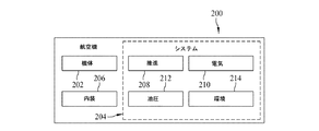
図2に示されるように、航空機の製造及び保守方法100によって製造された航空機200は、複数のシステム204及び内装206を有する機体202を含みうる。システム204の例には、推進システム208、電気システム210、油圧システム212、及び環境システム214のうちの一又は複数が含まれる。この例には任意の数の他のシステムが含まれてもよい。航空宇宙産業の例を示したが、本発明の原理は、自動車産業などの他の産業にも適用しうる。
As shown in FIG. 2, an
本明細書で具現化した装置及び方法は、航空機の製造及び保守方法100の一又は複数の段階で使用可能である。例えば、限定しないが、コンポーネント及びサブアセンブリの製造106に対応するコンポーネント又はサブアセンブリは、航空機200の運航中に製造されるコンポーネント又はサブアセンブリと同様の方法で作製又は製造しうる。
The apparatus and method embodied herein may be used in one or more stages of aircraft manufacturing and
また、一又は複数の装置の実施形態、方法の実施形態、又はこれらの組み合わせは、例えば、限定しないが、航空機200の組立てを実質的に効率化するか、又は航空機200のコストを削減することにより、コンポーネント及びサブアセンブリの製造106及びシステムインテグレーション108の段階で利用することができる。同様に、一又は複数の装置の実施形態、方法の実施形態、又はこれらの組み合わせは、航空機200が運行中であっても、例えば、限定しないが、整備及び保守114が行われるまでは、システムインテグレーション108及び/又は整備及び保守114の段階で、部品が互いに結合されているか及び/又は一致しているかを判断するため、利用することができる。
Also, one or more apparatus embodiments, method embodiments, or combinations thereof may, for example, without limitation, substantially increase the efficiency of
種々の有利な実施形態の説明は、例示及び説明を目的として提示されているものであり、網羅的な説明であること、又は開示された形態に実施形態を限定することを意図していない。当業者には、多数の修正例及び変形例が明らかであろう。さらに、種々の有利な実施形態は、他の有利な実施形態とは別の利点を提供することができる。選択された一又は複数の実施形態は、実施形態の原理、実際の用途を最もよく説明するため、及び他の当業者に対し、様々な実施形態の開示と、考慮される特定の用途に適した様々な修正との理解を促すために選択及び記述されている。 The descriptions of the various advantageous embodiments are presented for purposes of illustration and description, and are not intended to be exhaustive or limited to the embodiments disclosed. Many modifications and variations will be apparent to practitioners skilled in this art. Furthermore, the various advantageous embodiments can provide other advantages than the other advantageous embodiments. The selected embodiment or embodiments are best suited to explain the principles of the embodiment, the actual application, and to others skilled in the art for the disclosure of the various embodiments and the particular application considered. Selected and described to facilitate understanding of various modifications.
図3はパッシブ型RFIDシステム300の単純なブロック図である。システム300はRFIDリーダー310と少なくとも1つのパッシブ型RFIDタグを含む。そのタグは概して、その存在及び/又は位置が特定の領域内にあることが検証されているアイテム324に固定されている。図に示したように、RFIDリーダー310は送信アンテナ330及び受信アンテナ340を含む。実施形態によっては、アンテナ330及び340は多重化された単一のアンテナであってもよい。操作中、RFIDリーダー310は概して特定の周波数である信号350を送信し、その周波数はRFIDタグ320に共振を引き起こす。信号350は起動信号と呼ばれることがある。信号350は、搬送周波数で振幅変調された信号など、変調された信号であってもよい。信号350はさらに特定の出力で送信される。周知のように、RFIDタグ320に関連しているアンテナ360で信号350を受信することによってRFIDタグ320が共振されると、今度は受信アンテナ340によって受信可能な信号370の送信を開始する。信号370は、RFIDリーダー310によって読み取り可能なデータを含む。図3に示したように、信号370は振幅変位キーイング(ASK)変調信号、位相変位キーイング(PSK)変調信号、又は他の形式の変調信号であってもよい。RFIDリーダー310は、信号370の受信がアイテム324の一又は複数の存在、位置、又は他の識別子を示すようにプログラムされている。
FIG. 3 is a simple block diagram of a
図4は分散型アンテナシステム(DAS)を組み込んだパッシブ型RFIDシステム400のブロック図である。システム400は、送信出力412及び受信出力414がDAS処理機能420に結合されており、送信出力412及び受信入力414がアンテナハブ430に結びつけられているRFIDリーダー410を含む。アンテナハブ430は、アンテナ装置440、442、及び444と通信可能に結合されている。アンテナ装置440、442、及び444のうちの任意の一乃至複数個は、その位置に応じて、アイテム452のRFIDタグ450との間で信号の送信及び受信を行うことができる。分散型アンテナシステムを利用することにより、RFIDリーダーのレンジが延びても、RFIDの読取速度及び精度は改善される。1つの実施形態では、受信した電力は同等な受信出力に対して最大10dBまで増やされる。さらに、アンテナのヌル点の領域は小さくするか解消することができる。DAS及びヌル点の解消により、読取精度を100%まで改善し、さらに読取速度を上げ、受信出力を合計で15dB高めることができる。このような改善によりパッシブ型RFIDの読取レンジは10倍まで増加し、携帯用パッシブ型RFIDタグに関しては、読取速度が10倍まで増加する。さらに、DASを組み込むことにより、RFIDリーダーを1箇所に維持したままで、複数のRFIDタグ450との間で信号を送受信する機能を提供することができる。現在の多くの用途では、RFIDリーダーから発せられてRFIDタグに到達する信号がパッシブ型タグに共振を引き起こすだけの十分な出力を有するよう、RFIDリーダーは定められた経路に沿って移動させなければならない。図4及びその後の図では、分散型アンテナシステム内に3個のアンテナ装置がある例を取り上げているが、当業者であれば、DAS内のアンテナ装置の数は、アンテナパターン、アンテナ装置自体の送信パターン(例えば、個別の送信パターンにおけるヌル点のサイズ及び形状)、及びアンテナ装置の配置可能な位置によって網羅される領域に依存することを理解している。
FIG. 4 is a block diagram of a
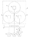
図5は、例えば、航空機の客室又は貨物室エリア500内に装備されたアンテナ装置440、442、及び444の発信信号の図解である。図5で利用され、図4に示されているコンポーネントと共通になりうるコンポーネントは同一の参照番号を用いて描かれている。本発明の実施形態では、アンテナ装置の構成又は分布は、一又は複数の航空機客室、貨物室エリア、航空機の機械設備エリア、翼、又は航空機に関連するその他の所定のエリアに対してカバレッジを提供するように装備しうる。
FIG. 5 is an illustration of outgoing signals of
1つの態様では、アンテナ装置440、442、及び444の各々が対応する送信パターン(それぞれ、460、462及び464)を有し、特定のアンテナ装置が送信しているときに内部にあるRFIDタグに共振が引き起こされることを図解するために図5を提示している。図5はさらに、エリア内のすべてのRFIDタグが少なくとも1つのアンテナ装置からの送信によって起動され、送信パターンによって全エリアが網羅可能となるようにアンテナ装置が装備されうることを図解している。具体的には図示しているように、送信パターン460、462、及び464が重なり合って全エリアのカバレッジを保証するように、アンテナ装置440、442、及び444は配置可能である。最後に、図5は、分散型アンテナシステムが、複数の通信サービスに対して送信及び受信機能を提供するように装備可能であることを図解している。より具体的には、分散型アンテナシステムは、RFIDリーダー410によるRFID通信、WiFi装置510によるWiFi通信、及び3G(又は他の)セルラー通信装置520によるセルラー通信などを複数サポートするように利用可能である。RFID、WiFi、及びセルラー通信は本システムによって同時に実現しうる。
In one aspect, each of the
光ファイバー分散型アンテナシステム(DAS)は、任意の数のアンテナ装置にアナログ信号を分配するファイバーリンクに複数の全二重無線を使用する。ダウンリンクに関して、信号は、アンテナスイッチングハブ430のアクセスポイント又は基地局から得られ、レーザーダイオードのバイアス電流を直接制御するために使用され、最終的にRF信号によって強度が変調される光になる。光信号はファイバーを介して送信され、アンテナ装置440、442、及び444内のフォトダイオードによって検出される。結果的に得られるRF信号は次に無線送信によって増幅される。アップリンクは、アンテナ装置440、442、及び444内部で入ってくるRF信号が増幅され、その結果生じる信号が使用されて直接レーザーを変調するように、同様であるが逆向きに動作する。その光出力は次にファイバーを経て、アンテナスイッチングハブ430まで運ばれる。1つの実施形態では、アンテナスイッチングハブ430とアンテナ装置440、442、及び444との間のキャリアはシングルモードファイバーである。1つの実施形態では、アンテナスイッチングハブ430とアンテナ装置440、442、及び444との間のキャリアはマルチモードファイバーである。横モードレーザー送信機のアナログ変調により、高周波(3dBを超えるマルチモード帯域幅)を使用して情報を送信することができる。アンテナ装置440,442、及び444は光信号を無線送信用のRFに変換する。1つの実施形態では、アンテナスイッチングハブ430とアンテナ装置440、442、及び444との間のキャリアは同軸ケーブルである。1つの実施形態では、アンテナ装置440,442、及び444は送信に先立ってRF信号を増幅する。複数のアンテナ装置を使用した場合、総出力電力は低減可能で、その結果、アンテナスイッチングハブ430とアンテナ装置440、442、及び444との間の光リンクのダイナミックレンジは低減可能となる。
A fiber optic distributed antenna system (DAS) uses multiple full-duplex radios in a fiber link that distributes analog signals to any number of antenna devices. For the downlink, the signal is obtained from the access point or base station of the
ある種の分散型アンテナシステムは光ファイバー通信を組み込むことが可能で、その結果、すべての電流通信サービスに対応可能な広い帯域幅を提供することができる。航空機の用途では、このような共通インフラストラクチャにRFID機能を追加することにより、航空機への新たな「システム」(例えば、重量、スペース、コスト、及び重量による燃料消費の増加など)の導入に伴う多くの困難を克服することができる。 Certain distributed antenna systems can incorporate fiber optic communications, and as a result can provide a wide bandwidth that can accommodate all current communication services. In aircraft applications, adding RFID functionality to such a common infrastructure, along with the introduction of new “systems” (eg, increased fuel consumption due to weight, space, cost, and weight) Many difficulties can be overcome.
既に述べたように、航空機に搭載される低コストのパッシブ型RFIDタグを含む正確なリアルタイム位置特定システムによって、例えば乗客、手荷物の位置確認、救命胴衣装備の総数確認、携帯用搭載アイテムの在庫保持が可能になり、また、完全な無線電子機器(センサー)の物理的な位置を客室サービス用の論理アドレスにマッピングすることが可能になる。 As already mentioned, an accurate real-time location system, including low-cost passive RFID tags mounted on aircraft, for example, passenger, baggage location, total number of life jackets, and inventory of portable items And the physical location of a complete wireless electronic device (sensor) can be mapped to a logical address for room service.
RFIDリアルタイム位置特定システムは、航空機全体にわたって配置されている座席電子ボックス(SEB)のデイジーチェーンを含む機内娯楽システムで、複数の有線SEB間での登録トークンの受け渡しに基づく各SEBの位置を特定するための代替方法として使用することができる。 The RFID real-time location system is an in-flight entertainment system that includes a daisy chain of seated electronic boxes (SEBs) that are located throughout the aircraft and locates each SEB based on the passing of registration tokens between multiple wired SEBs. Can be used as an alternative method.
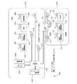
次に図6に注目すると、複数のRFIDとの通信に利用される分散型アンテナシステム(DAS)及びリモートDASの航空機600内での1つの実施形態が図解されている。
航空機600はメイン客室610及び貨物室620を含む。図解した実施形態では、ユニバーサル無線分散システム630は、航空機通信ネットワーク640と通信可能に結合されている。ユニバーサル無線分散システム630は、前図に関連して説明したアンテナハブ機能を果たす。同様に、ユニバーサル無線分散システム630は、RFIDリーダー650及び通信機器660と通信可能に結合されている。通信機器660はWiFi及び/又はセルラー通信用のインターフェースに相当する。図5の図解と同様に、ユニバーサル無線分散システム630は、メイン客室610用のDASを構成するアンテナ装置670、672、及び674に結合されている。
Turning now to FIG. 6, one embodiment within an
航空機の客室内で、アンテナ装置670、672、及び674はパッシブ型RFIDタグ680、682、684、及び686を起動する送信機能を提供する。これらのタグはそれぞれ、携帯無線機器690、低電力無線機器692、乗客694、及び救命胴衣696と結合されている。RFIDタグ配置に関するこれらの代表例は、例にすぎないことを理解されたい。ある実施形態では、乗客はRFIDタグには適合しないこと、また、航空機客室内の他のデバイスにRFIDがつけられることがある。すなわち、RFIDタグが配置されるアイテムは、用途に応じて決定される。しかしながら、どのような用途であっても、本明細書に記載されているとおり、タグはすべて、アンテナ装置670、672、及び674の分散型アンテナシステム及びこれらのアンテナ装置の支持コンポーネントを介して起動可能となっている。パッシブ型RFIDタグが取付けられる各個別アイテム(例えば、救命胴衣696)は複数個ある場合があることを理解すべきである。
In an aircraft cabin,
ユニバーサル無線分散システム630はまた、アンテナ装置710、712、及び714が結合されるリモート分散型アンテナシステム制御装置700に結合される。リモート分散型アンテナシステム制御装置700とアンテナ装置710、712、及び714は、貨物室620内のアイテムに配置されたRFIDタグ720、722、及び724の追跡に利用することができる。図示されている実施例では、各アイテムは低電力無線機器730、携帯無線機器732、及び手荷物734を含んでいる。さらに、これらのアイテムは例示に過ぎず、メイン客室610、貨物室620及び航空機の他の領域内にある多数の様々なアイテムにパッシブ型RFIDタグを添付し、図6に示したものと同様な分散型アンテナシステムによって起動することが可能である。航空機の他の領域内のリモートDASもまた、ユニバーサル無線分散システム630を介して、例えばRFIDリーダー650及び通信機器660と通信可能に結合することができる。
The universal
1つの実施形態では、乗客のインターネット接続、携帯電話、及び分散型航空機機能などの複数の無線システムに対応するすべての無線信号を結合することによって、ユニバーサル無線分散システム630は、有線航空機ネットワーク640との無線航空機ネットワークとの間のゲートウェイとしての役割を果たす。
In one embodiment, the universal
ユニバーサル無線分散システム(UWDS)630は、1つの実施形態では漏洩フィーダー同軸アンテナとなる分散型アンテナシステム(DAS)を介して結合された信号を出力する。漏洩同軸分散システムは、航空機に搭載される通信サービスに対応する分散型アンテナシステムの代替を提供するため、漏洩同軸分散システムはまた、分散型アンテナ装置を介して放射される場合には、システム航空機に搭載されるパッシブ型RFIDリアルタイム位置特定システムにも対応する。 Universal wireless distributed system (UWDS) 630 outputs the combined signal through a distributed antenna system (DAS), which in one embodiment is a leaky feeder coaxial antenna. The leaky coaxial distributed system also provides an alternative to the distributed antenna system corresponding to the communication service installed on the aircraft, so that the leaky coaxial distributed system is also a system aircraft when radiated through the distributed antenna device. It corresponds to the passive type RFID real-time location system mounted on the PC.
RDAS700は無線データ収集装置の一実施形態で、航空機の機能を提供することができ、また図に示したように一又は複数の低電力無線機器に対して無線ブリッジとして機能することができる。これらの無線データ収集装置はまた、機体外側又は他の航空機のコンパートメント内など、UWDSの無線ネットワークカバレージ領域外のサプリカントに対して拡張された無線ネットワークカバレージを提供する。実施形態によっては、可用性、信頼性、及びネットワークカバレージを増すため、無線データ収集装置は無線マルチホップリレーネットワークを形成する。その結果、UWDS630の無線ネットワークカバレージ領域の範囲内にあるノートブックコンピュータ及び携帯電話(及び携帯無線機器690と732)などの複数の携帯無線機器は、UWDSに直接接続されるか、UWDSカバレージ領域外にある場合には無線データ収集装置の1つに接続される。実施形態によっては、無線センサー又は無線スイッチなどの複数の無線機器はまた、無線データ収集装置を介してネットワークに接続される。
The
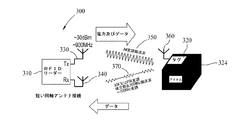
図7に図解したように、漏洩同軸ケーブルは分散型アンテナシステムへの代替アプローチを提供する。漏洩同軸ケーブルは構造的には通常の同軸ケーブルにきわめて類似している。しかしながら、ケーブルの外部導体に1つの違いがある。通常の同軸ケーブルはRF漏洩を最小限に抑えるように設計された外部導体シールドを使用する。これとは対照的に、一般的な漏洩同軸ケーブルの外部導体は、中心導体から周囲環境へ漏れ出すRF信号の量を制御できるよう、外部導体に形成された孔又は開口部を含む。信号の多くは依然としてケーブル通って中心導体上を移動するが、これらの開口部により、信号がケーブルから放射状に広がること、すなわち、電流が外部導体表面を移動することが可能になり、ケーブル周囲にRF場が形成される。 As illustrated in FIG. 7, leaky coaxial cables provide an alternative approach to distributed antenna systems. Leaky coaxial cables are structurally very similar to ordinary coaxial cables. However, there is one difference in the outer conductor of the cable. Conventional coaxial cables use outer conductor shields designed to minimize RF leakage. In contrast, the outer conductor of a typical leaky coaxial cable includes a hole or opening formed in the outer conductor so that the amount of RF signal that leaks from the center conductor to the surrounding environment can be controlled. Most of the signal still travels through the cable and over the central conductor, but these openings allow the signal to spread radially from the cable, i.e., current can travel on the outer conductor surface, around the cable. An RF field is formed.
結合モード又は放射モードのケーブルに関しては、ケーブルを連続した「蛍光灯」のエレメントとし、各エレメントが図7に図解したように、ランベルトの法則による放射パターンで拡散的に放射することを示すレイトレースモデルが十分に機能することがわかっている。送受信機器としての漏洩同軸ケーブルの性能は、設置される環境に依存する。連成効果と挿入損失との間、及び室内環境と室外環境との間には差異があり、また、漏洩同軸ケーブルが散乱の多い環境に置かれているか散乱のない環境に置かれているかで差異がある。分散型アンテナシステムに対して実証されているRFID位置特定方法は、様々な環境にある漏洩同軸ケーブルの結合モード特性に合わせて調整されるものと予測される。 For coupled or radiating mode cables, the ray trace is a continuous “fluorescent” element, and each element radiates diffusely with a radiation pattern according to Lambert's Law, as illustrated in FIG. The model is known to work well. The performance of a leaky coaxial cable as a transmission / reception device depends on the installation environment. There is a difference between coupling effects and insertion loss, between indoor and outdoor environments, and whether the leaky coaxial cable is placed in a highly scattering or non-scattering environment. There is a difference. The proven RFID localization method for distributed antenna systems is expected to be tailored to the coupled mode characteristics of leaky coaxial cables in various environments.
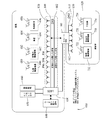
図7は、分散型アンテナシステム(DAS)として動作するように構成された、送信用の第1漏洩同軸ケーブル800及び受信用の第2同軸漏洩ケーブル802を有する航空機600内での装備の一実施形態を図解したものである。図6に図解した実施形態と同様に、追加の漏洩同軸ケーブル810及び812を経由して第2の複数のRFIDタグ720、722、及び724との通信に利用されるリモートDAS700も含まれている。図示されている実施形態では、ユニバーサル無線分散システム630は、図6に関連して既に述べたように同様な方法で、航空機通信ネットワーク640と通信可能に結合されている。1つの実施形態では、ユニバーサル無線分散システム630は、アップリンク信号とダウンリンク信号との間の干渉を防止するため、複数の周波数又は代替手段によって、単一の漏洩同軸ケーブルに結合されている。図示されている実施形態では、送信と受信を分離した同軸ケーブルアンテナ装置(800、802、810、及び812)が使用されている。送信に漏洩同軸ケーブル800及び810を組み込むことによって、複数の送信点820及び830が生成される。同様にして、受信に漏洩同軸ケーブル800及び810を組み込むことによって、複数の受信点820及び830が生成される。これらの送受信点は一般的に上述のアンテナ装置として動作し、各送受信点には同軸ケーブルの外部導体に開口部だけがあればよいため、漏洩同軸ケーブルには容易に送受信点を生成することが可能であることを除いて、本明細書の目的では「仮想的なアンテナ装置」とみなしうる。図6に関連して述べたような付加的なアンテナ装置の追加には、このような装置の収納に欠かせない空間が必要となる。ある種の用途においては、このような空間は割高となる。
FIG. 7 illustrates one implementation of the equipment in an
先行する図面は、パッシブ型RFIDタグのヌル点を減らし受信信号強度を高めるように個別のアンテナ装置の位置が最適化された分散型アンテナシステム(DAS)を含む機内搭載パッシブ型RFIDシステムに関連している。他の実施形態では、実質的に分散型アンテナシステムをシミュレートする漏洩同軸ケーブルが利用されている。実施形態によっては、分散型アンテナシステムを利用した場合、RFIDリーダーのレンジを拡張し、その結果等価送信電力に関して10dBだけ受信電力を高めることによって、RFID読取速度及び精度の改善が実現可能である。さらに、DAS及び漏洩同軸ケーブルの両実施形態で、アンテナヌル点の領域を小さくするか解消することができる。DAS及びヌル点の解消により、読取精度を100%まで改善し、さらに読取速度を上げ、受信出力を合計で15dB高めることができる。先行する因子を組み合わせることにより、パッシブ型RFIDタグの読取レンジを最大10倍まで増大させることができ、携帯用パッシブ型RFIDタグに関しては速度測定が可能になる。 The preceding drawings relate to an onboard passive RFID system that includes a distributed antenna system (DAS) in which the position of individual antenna devices is optimized to reduce the null point of the passive RFID tag and increase the received signal strength. ing. In other embodiments, a leaky coaxial cable that substantially simulates a distributed antenna system is utilized. In some embodiments, when using a distributed antenna system, it is possible to improve RFID reading speed and accuracy by extending the range of the RFID reader and consequently increasing the received power by 10 dB with respect to the equivalent transmit power. Furthermore, in both the DAS and leaky coaxial cable embodiments, the area of the antenna null point can be reduced or eliminated. By eliminating the DAS and the null point, it is possible to improve the reading accuracy to 100%, further increase the reading speed, and increase the reception output by 15 dB in total. By combining the preceding factors, the reading range of the passive RFID tag can be increased up to 10 times, and speed measurement is possible for portable passive RFID tags.
従来のRFID受信機システムと比較した場合、DAS RFID受信機システムに対してパッシブ型RFIDは改善されている。既に述べたRFIDシステムはまた、無線で指紋認証された客室内で一又は複数のパッシブ型RFIDタグを含むアイテムの特定を可能にする。DASを組み込むことにより、複数アンテナの位置特定技術を利用して、航空機内に分散配置された各種のパッシブ型RFIDタグの絶対位置精度を改善することができる。実施形態によっては、RFIDシステムは、航空機客室内の単一の座席又は座席グループ内にパッシブ型RFIDタグの位置を特定する機能を提供する。したがって、寸法に関しては、パッシブ型RFIDタグに対して提供される位置は約±0.5mの範囲内となる。さらに、DASを取り込むことによって、共通DASインフラストラクチャの上にWiFi及び携帯電話などの他の機内搭載HF帯、UHF帯及びSHF帯のデータサービスをリモート統合することが可能になる。 Compared to conventional RFID receiver systems, passive RFID is an improvement over DAS RFID receiver systems. The RFID system already described also allows the identification of items including one or more passive RFID tags in a wirelessly fingerprinted cabin. By incorporating the DAS, the absolute position accuracy of various passive RFID tags distributed in the aircraft can be improved by utilizing the multiple antenna positioning technology. In some embodiments, the RFID system provides the ability to locate passive RFID tags within a single seat or group of seats in an aircraft cabin. Thus, with respect to dimensions, the position provided for the passive RFID tag is in the range of about ± 0.5 m. Furthermore, by incorporating DAS, it is possible to remotely integrate other onboard HF, UHF, and SHF band data services such as WiFi and mobile phones over a common DAS infrastructure.
従前の位置特定システムはタグ1個について100倍以上も高価なアクティブ型RFIDタグに基づいたもので、精度及び分解能は限られていた。さらに、座席アームの読書灯調整ボタンなど、完全な無線機器に対する物理的な位置をマッピングする従前のアプローチは、複雑な有線トークンバス受け渡しスキームを使用して、頭上の読書灯の位置を座席アームの乗客灯調整ボタンにマッピングする。 Conventional location systems are based on active RFID tags that are more than 100 times more expensive per tag and have limited accuracy and resolution. In addition, previous approaches to mapping the physical location to a complete wireless device, such as the reading light adjustment button on the seat arm, use a complex wired token bus delivery scheme to position the overhead reading light position on the seat arm. Map to the passenger light adjustment button.
このようなアプローチの1つの問題点は、航空機内の有線接続が概して望ましくない航空機の重量増加をもたらす結果になることである。したがって、記載した実施形態は、物理的な位置を論理的なネットワーク位置にマッピングするのに配線を必要とないため、先行するソリューションよりも優れている。リアルタイムでのアイテムの位置特定に関して、実施形態は、在庫される動かないアイテムの位置特定に、また、例えば搭乗券に印刷されたRFIDタグによる移動する乗客の位置追跡に、低コストのパッシブ型RFIDタグを使用する方法、さらには旅程表付き荷物とパッシブ型RFIDタグ付き手荷物との関連付けについて説明している。 One problem with such an approach is that wired connections within the aircraft result in aircraft weight gain that is generally undesirable. Thus, the described embodiments are superior to previous solutions because no wiring is required to map physical locations to logical network locations. With respect to locating items in real time, embodiments provide low-cost passive RFID for locating stationary items that are in stock, and for tracking moving passengers, for example with RFID tags printed on boarding passes. A method of using a tag, and further, an association between an itinerary package and a passive RFID tag baggage are described.
要約すると、説明した実施形態は、無線で指紋認証された航空機客室内のアイテムの特定、及びパッシブ型RFIDタグの絶対位置精度を単一の座席又は座席グループ内(例えば、±0.5m)に収まるように改善する組み込み型の複数アンテナ位置特定技術に有用である。上述のシステムはまた、共通DASインフラストラクチャの上にWiFi及び携帯電話などの他の機内搭載無線データサービスをリモート統合する際に有用である。 In summary, the described embodiments identify items in an aircraft cabin that are wirelessly fingerprinted and the absolute position accuracy of a passive RFID tag within a single seat or group of seats (eg, ± 0.5 m). This is useful for embedded multi-antenna location techniques that improve to fit. The system described above is also useful in remotely integrating other onboard wireless data services such as WiFi and mobile phones over a common DAS infrastructure.
本明細書では、最良のモードを含め、様々な実施形態を開示する実施例を使用しているため、当業者は任意の機器やシステムの作成並びに使用、及び組込まれた任意の方法の実施を含む実施形態を実行することができる。特許可能な範囲は特許請求の範囲によって定義されており、当業者であれば想起される他の実施例も含みうる。このような他の実施例は、それらが特許請求の範囲の文字言語から逸脱しない構造要素を有する場合、あるいは、それらが特許請求の範囲の文字言語と非実質的な相違を有する等価な構造要素を含んでいる場合は、特許請求の範囲の範囲内にあることを意図している。 This document uses examples disclosing various embodiments, including the best mode, so that those skilled in the art will be able to create and use any device or system and perform any method incorporated. Including embodiments can be performed. The patentable scope is defined by the claims, and may include other examples that occur to those skilled in the art. Such other embodiments may have structural elements that do not deviate from the claimed language, or equivalent structural elements that have insubstantial differences from the claimed language. Is intended to be within the scope of the claims.
Claims (28)
前記航空機内の第2の固定位置に配置された通信機660、並びに
航空機通信ネットワーク640と通信可能に結合された無線分散システム630と、前記無線分散システム630と通信可能に結合された送受信点であって、前記航空機200内の複数のパッシブ型RFIDタグ320が、前記送信点のうちの少なくとも1つによって出力される信号によって起動されうるように航空機200全体に分散配置された前記送受信点とを備えた分散型アンテナシステム
を備えた航空機通信及びアイテム追跡システムであって、前記RFIDリーダー310及び前記通信機器660が前記無線分散システム630と通信可能に結合されており、前記分散型アンテナシステムが、前記RFIDリーダー310及び前記パッシブ型RFIDタグ320に関連する信号の送受信に対して操作可能であり、さらに、前記通信機器660と関連する信号の送受信に対して操作可能である、システム。 An RFID reader 310 disposed at a first fixed position in the aircraft 200;
A communication device 660 disposed at a second fixed position in the aircraft; a wireless distributed system 630 communicatively coupled to an aircraft communication network 640; and a transmission / reception point communicatively coupled to the wireless distributed system 630. A plurality of passive RFID tags 320 in the aircraft 200 that are distributed throughout the aircraft 200 such that the passive RFID tags 320 can be activated by a signal output by at least one of the transmission points. An aircraft communication and item tracking system comprising a distributed antenna system, wherein the RFID reader 310 and the communication device 660 are communicatively coupled to the wireless distributed system 630, the distributed antenna system comprising: In the RFID reader 310 and the passive RFID tag 320 A system operable for transmission / reception of related signals and further operable for transmission / reception of signals related to the communication device 660.
ム。 The system of claim 1, wherein the distributed antenna system comprises an optical fiber communication function.
少なくとも1つのリモート分散アンテナシステム制御装置700、及び
前記少なくとも1つのリモート分散アンテナシステム制御装置と通信可能に結合された複数の付加的な送受信点
をさらに備え、前記少なくとも1つのリモート分散型アンテナシステム制御装置700が、前記無線分散システム630と通信可能に結合されており、前記少なくとも1つのリモート分散型アンテナシステム制御装置及び前記付加的な送受信点が、前記RFIDリーダー310と、前記第2の複数のパッシブ型RFIDタグ320とに関連する信号の送受信に対して操作可能である、請求項1に記載のシステム。 A second plurality of passive RFID tags 720, 722, 724, operable in connection with items in the second compartment of the aircraft;
At least one remote distributed antenna system controller 700; and a plurality of additional transceiver points communicatively coupled to the at least one remote distributed antenna system controller, the at least one remote distributed antenna system controller A device 700 is communicatively coupled to the wireless distributed system 630, wherein the at least one remote distributed antenna system controller and the additional transceiver point are the RFID reader 310, the second plurality of transmission points. The system of claim 1, wherein the system is operable for transmission and reception of signals associated with the passive RFID tag 320.
複数のアンテナ装置と、
外部導体を有する漏洩同軸ケーブルであって、該外部導体内に一又は複数の開口部を更に有する少なくとも1つの漏洩同軸ケーブルと
のうち少なくとも1つを備えた、請求項1に記載のシステム。 The transmission / reception point is
A plurality of antenna devices;
The system of claim 1, comprising at least one of a leaky coaxial cable having an outer conductor and at least one leaky coaxial cable further having one or more openings in the outer conductor.
前記航空機内の固定式RFIDリーダー310からの起動信号であって、パッシブ型RFIDタグ320を起動するように操作可能な前記信号を出力するステップと、
分散型アンテナシステムの送信点、前記航空機内に分散配置されている前記分散型アンテナシステムの個別の送受信点、少なくとも1つの他の通信システムに対して通信機能を提供する前記分散型アンテナシステムを経由する送信に対する前記RFIDリーダー310からの前記起動信号の経路を決定するステップと、
前記送信された起動信号によって起動された前記パッシブ型RFIDタグ320によって生成された信号を、前記分散型アンテナシステムの分散配置された受信点を介して受信するステップと、
前記RFIDリーダー310による解釈に対して前記分散型アンテナシステムを介して前記受信信号の経路を決定するステップと
を含む方法。 A method of tracking items on an aircraft 200, wherein each item is trackable in association with at least one passive RFID tag 310, the method comprising:
Outputting an activation signal from a stationary RFID reader 310 in the aircraft that is operable to activate a passive RFID tag 320;
Via a transmission point of the distributed antenna system, individual transmission / reception points of the distributed antenna system distributed in the aircraft, via the distributed antenna system providing a communication function for at least one other communication system Determining the path of the activation signal from the RFID reader 310 for transmission to be performed;
Receiving a signal generated by the passive RFID tag 320 activated by the transmitted activation signal via distributed reception points of the distributed antenna system;
Determining the path of the received signal through the distributed antenna system for interpretation by the RFID reader 310.
前記複数の無線通信機器660に対する通信アクセスポイントとして操作可能な無線分散システム、並びに
前記無線分散システムと通信可能に結合された複数の個別の送受信点
を備え、前記無線分散システムが共通インフラストラクチャ上に複数の通信サービスを統合するように操作可能であり、前記通信サービスのうち少なくとも1つが前記少なくとも1つのパッシブ型RFIDタグリーダー650に関連しており、前記送受信点に関連する送信パターンが提供されることによって、前記航空機内に装備された複数のパッシブ型RFID機器との通信が可能になるように、前記送受信点が前記航空機内に分散配置されている、航空機。 A plurality of wireless communication devices installed in the aircraft including at least one passive RFID reader 650;
A wireless distributed system operable as a communication access point for the plurality of wireless communication devices 660, and a plurality of individual transmission / reception points communicatively coupled to the wireless distributed system, the wireless distributed system on a common infrastructure Operable to integrate a plurality of communication services, wherein at least one of the communication services is associated with the at least one passive RFID tag reader 650 and a transmission pattern associated with the transceiver point is provided Thus, the transmission / reception points are dispersedly arranged in the aircraft so as to enable communication with a plurality of passive RFID devices installed in the aircraft.
Applications Claiming Priority (3)
| Application Number | Priority Date | Filing Date | Title |
|---|---|---|---|
| US12/632,501 | 2009-12-07 | ||
| US12/632,501 US10181060B2 (en) | 2009-12-07 | 2009-12-07 | Methods and systems for real time RFID locating onboard an aircraft |
| PCT/US2010/058976 WO2011071781A1 (en) | 2009-12-07 | 2010-12-03 | Methods and systems for real time rfid locating onboard an aircraft |
Publications (2)
| Publication Number | Publication Date |
|---|---|
| JP2013512824A true JP2013512824A (en) | 2013-04-18 |
| JP2013512824A5 JP2013512824A5 (en) | 2014-01-09 |
Family
ID=43533155
Family Applications (1)
| Application Number | Title | Priority Date | Filing Date |
|---|---|---|---|
| JP2012542227A Pending JP2013512824A (en) | 2009-12-07 | 2010-12-03 | Method and system for real-time RFID for location on board an aircraft |
Country Status (6)
| Country | Link |
|---|---|
| US (1) | US10181060B2 (en) |
| EP (1) | EP2534607B1 (en) |
| JP (1) | JP2013512824A (en) |
| CN (2) | CN102648473A (en) |
| CA (1) | CA2792986C (en) |
| WO (1) | WO2011071781A1 (en) |
Cited By (4)
| Publication number | Priority date | Publication date | Assignee | Title |
|---|---|---|---|---|
| JP2015531222A (en) * | 2012-06-26 | 2015-10-29 | ザ・ボーイング・カンパニーTheBoeing Company | Wireless power recovery along multiple paths in the reverberant air gap |
| JP2016084237A (en) * | 2014-10-22 | 2016-05-19 | ザ・ボーイング・カンパニーThe Boeing Company | Systems and methods for verifying location of item |
| JP2017041231A (en) * | 2015-08-03 | 2017-02-23 | ザ・ボーイング・カンパニーThe Boeing Company | Method for associating wireless sensors to physical locations |
| JP2017159899A (en) * | 2016-03-07 | 2017-09-14 | アストロニクス アドバンスド エレクトロニック システムズ コーポレイション | Network system for autonomous data collection |
Families Citing this family (44)
| Publication number | Priority date | Publication date | Assignee | Title |
|---|---|---|---|---|
| US9590733B2 (en) * | 2009-07-24 | 2017-03-07 | Corning Optical Communications LLC | Location tracking using fiber optic array cables and related systems and methods |
| FR2956648B1 (en) * | 2010-02-23 | 2012-05-11 | Eurocopter France | OPTIMIZATION OF CONFIGURATION ASSEMBLY OF A WIRELESS NETWORK MESH OF RADIOFREQUENCY DEVICES IN AN AIRCRAFT |
| GB201006907D0 (en) * | 2010-04-26 | 2010-06-09 | Cambridge Entpr Ltd | RFID TAG interrogation systems |
| KR20110127968A (en) * | 2010-05-20 | 2011-11-28 | 엘에스산전 주식회사 | Remote control transmitter/receiver using rfid and method thereof |
| US9113234B2 (en) * | 2010-07-27 | 2015-08-18 | The Boeing Company | Wireless device association system |
| US9590761B2 (en) | 2011-09-23 | 2017-03-07 | Commscope Technologies Llc | Detective passive RF components using radio frequency identification tags |
| US20130181867A1 (en) * | 2012-01-13 | 2013-07-18 | Rick Sturdivant | Location Determination System and Method Using Array Elements for Location Tracking |
| EP2891288B1 (en) * | 2012-08-31 | 2019-10-09 | CommScope Technologies LLC | Detecting passive rf components using radio frequency identification tags |
| CN103729606B (en) * | 2012-10-11 | 2016-12-21 | 刘台华 | There is the frequency identification electronic device strengthening surface duct effect |
| KR101514066B1 (en) * | 2013-04-01 | 2015-04-21 | 자바무선기술(주) | Apparatus of clamping RFID antenna for forklift truck |
| US9147295B2 (en) | 2013-06-21 | 2015-09-29 | X-Card Holdings, Llc | Inductive coupling activation systems and methods |
| US9477865B2 (en) * | 2013-12-13 | 2016-10-25 | Symbol Technologies, Llc | System for and method of accurately determining true bearings of radio frequency identification (RFID) tags associated with items in a controlled area |
| US9755294B2 (en) | 2014-07-07 | 2017-09-05 | Symbol Technologies, Llc | Accurately estimating true bearings of radio frequency identification (RFID) tags associated with items located in a controlled area |
| CN105270643A (en) * | 2014-10-24 | 2016-01-27 | 栗中华 | Device and method for managing airplane protective articles |
| EP3067843A1 (en) * | 2015-03-09 | 2016-09-14 | BAG2GO GmbH | Method and system for identifying flight baggage |
| US9521678B2 (en) | 2015-03-12 | 2016-12-13 | The Boeing Company | Wireless data concentrators for aircraft data networks |
| US10063428B1 (en) * | 2015-06-30 | 2018-08-28 | Apstra, Inc. | Selectable declarative requirement levels |
| US9380428B1 (en) * | 2015-07-02 | 2016-06-28 | The Boeing Company | Location-based services onboard aircraft |
| US9646187B2 (en) * | 2015-07-31 | 2017-05-09 | The Boeing Company | Systems and methods for automated device pairing |
| US9773136B2 (en) | 2015-10-19 | 2017-09-26 | Symbol Technologies, Llc | System for, and method of, accurately and rapidly determining, in real-time, true bearings of radio frequency identification (RFID) tags associated with items in a controlled area |
| EP3182609B1 (en) * | 2015-12-17 | 2019-02-20 | Airbus Operations GmbH | Wireless data transmitting device and method for wireless data transmission |
| US9551780B1 (en) * | 2016-01-02 | 2017-01-24 | International Business Machines Corporation | Locating an object based on charging/response time |
| US9766621B2 (en) * | 2016-01-12 | 2017-09-19 | The Boeing Company | Aircraft information retrieval using onboard RFID tags |
| KR101746020B1 (en) * | 2016-02-26 | 2017-06-14 | 전자부품연구원 | Method, System and Apparatus for Backscattering Communication Using CSI |
| CN106203210B (en) * | 2016-06-29 | 2018-11-23 | 南京航空航天大学 | Extensive RFID system medion estimator method based on range estimation |
| US10382569B2 (en) * | 2016-08-29 | 2019-08-13 | The Boeing Company | Local positioning with communication tags |
| US10061951B2 (en) * | 2016-11-30 | 2018-08-28 | Wipro Limited | Methods and systems for localizing articles comprising passive radio frequency identification (RFID) tags |
| US10136341B2 (en) | 2017-01-03 | 2018-11-20 | Simmonds Precision Products, Inc. | Wireless data concentrator systems and methods |
| CA3053541A1 (en) | 2017-02-14 | 2018-08-23 | Systems And Software Enterprises, Llc | Systems and methods for steering wireless network traffic within a vehicle |
| US10726218B2 (en) | 2017-07-27 | 2020-07-28 | Symbol Technologies, Llc | Method and apparatus for radio frequency identification (RFID) tag bearing estimation |
| GB201714992D0 (en) * | 2017-09-18 | 2017-11-01 | Cambridge Entpr Ltd | RFID systems |
| CN108199944B (en) * | 2017-12-15 | 2020-12-18 | 中国航空工业集团公司上海航空测控技术研究所 | Onboard cabin core system of dynamic daisy chain ring network and dynamic positioning method |
| JP7349726B2 (en) * | 2018-01-12 | 2023-09-25 | 株式会社NejiLaw | Information dissemination system |
| US11218871B2 (en) * | 2018-04-09 | 2022-01-04 | Simmonds Precision Products, Inc. | Portable wireless communication adapter for avionics frequencies selectively enabled based on location within aircraft |
| CN109165537B (en) * | 2018-07-30 | 2021-07-30 | 太原理工大学 | Back scattering label distributed rate self-adaptive algorithm based on bit-rate-free code |
| CN113454426A (en) * | 2018-12-20 | 2021-09-28 | 舍弗勒技术股份两合公司 | Detection system and wind driven generator |
| CN109707585B (en) * | 2018-12-20 | 2020-07-07 | 浙江大学 | Laser propulsion method based on phased array control |
| US10872514B1 (en) | 2019-08-14 | 2020-12-22 | The Boeing Company | Safety system for tracking movable objects during vehicle production |
| CN110569941A (en) * | 2019-09-28 | 2019-12-13 | 东方航空技术有限公司 | RFID-based aviation life jacket management method and device |
| CN115428365B (en) * | 2020-09-11 | 2024-01-23 | Oppo广东移动通信有限公司 | Symbol detection method, device and system |
| CN112698591A (en) * | 2020-11-26 | 2021-04-23 | 上海工程技术大学 | Airport boarding bridge intelligent monitoring system |
| EP4187432A1 (en) * | 2021-11-26 | 2023-05-31 | HID Textile Services SARL | System for reading rfid tags |
| US11675043B1 (en) * | 2021-11-29 | 2023-06-13 | Goodrich Corporation | Wireless tracking and ranging for cargo systems |
| CN114936569B (en) * | 2022-04-26 | 2023-04-14 | 南昌三瑞智能科技有限公司 | Power system integrating wireless radio frequency electronic tags and unmanned aerial vehicle |
Citations (8)
| Publication number | Priority date | Publication date | Assignee | Title |
|---|---|---|---|---|
| US5534869A (en) * | 1990-02-20 | 1996-07-09 | Auratek Security Inc. | Open transmission line locating system |
| JPH11225113A (en) * | 1997-11-20 | 1999-08-17 | Kokusai Electric Co Ltd | Optical conversion relay amplifier system |
| JP2004294338A (en) * | 2003-03-27 | 2004-10-21 | Matsushita Electric Works Ltd | Spatial position control system |
| US20060038077A1 (en) * | 2004-06-10 | 2006-02-23 | Goodrich Corporation | Aircraft cargo locating system |
| US20070001809A1 (en) * | 2005-05-02 | 2007-01-04 | Intermec Ip Corp. | Method and system for reading objects having radio frequency identification (RFID) tags inside enclosures |
| US20070218951A1 (en) * | 2006-03-16 | 2007-09-20 | Cellynx, Inc. | Cell Phone Signal Booster |
| US20070257796A1 (en) * | 2006-05-08 | 2007-11-08 | Easton Martyn N | Wireless picocellular RFID systems and methods |
| JP2009540753A (en) * | 2006-06-12 | 2009-11-19 | コーニング ケーブル システムズ リミテッド ライアビリティ カンパニー | Centralized optical fiber based wireless picocellular system and method |
Family Cites Families (16)
| Publication number | Priority date | Publication date | Assignee | Title |
|---|---|---|---|---|
| US6246320B1 (en) * | 1999-02-25 | 2001-06-12 | David A. Monroe | Ground link with on-board security surveillance system for aircraft and other commercial vehicles |
| US6281797B1 (en) * | 2000-04-04 | 2001-08-28 | Marconi Data Systems Inc. | Method and apparatus for detecting a container proximate to a transportation vessel hold |
| US9151692B2 (en) * | 2002-06-11 | 2015-10-06 | Intelligent Technologies International, Inc. | Asset monitoring system using multiple imagers |
| US7030760B1 (en) * | 2001-08-07 | 2006-04-18 | Seecontrol, Inc. | Method and apparatus for ensuring reliable loading of materials on aricraft and other vehicles |
| DE10210037A1 (en) * | 2002-03-07 | 2003-10-02 | Siemens Ag | Active backscatter transponder, communication system with such an and method for transmitting data with such an active backscatter transponder |
| DE10301451A1 (en) * | 2003-01-10 | 2004-07-22 | Atmel Germany Gmbh | Wireless data transmission method between base station and transponder, by modulating electromagnet waves at receiver using modulation technique based on received field strength |
| US20040229607A1 (en) | 2003-05-12 | 2004-11-18 | La Chapelle Michael De | Wireless communication inside shielded envelope |
| EP1844455A4 (en) * | 2004-09-28 | 2009-02-11 | Visible Assets Inc | Rf tags for tracking and locating travel bags |
| DE502006006574D1 (en) * | 2005-01-13 | 2010-05-12 | Rheinmetall Defence Elect Gmbh | DEVICE AND METHOD FOR CONTROLLING THE OPENING AND / OR UNLOADING PROCESS OF AN AIRCRAFT |
| US7319854B2 (en) * | 2005-04-29 | 2008-01-15 | The Boeing Company | Automatic airplane seat location mapping |
| US7528726B2 (en) * | 2006-05-26 | 2009-05-05 | Yeon Technologies Co., Ltd. | RFID portal array antenna system |
| US20070285239A1 (en) | 2006-06-12 | 2007-12-13 | Easton Martyn N | Centralized optical-fiber-based RFID systems and methods |
| KR20080015974A (en) | 2006-08-17 | 2008-02-21 | 브레인즈스퀘어(주) | Asset management system using wifi and method thereof |
| CN101589396A (en) * | 2006-11-27 | 2009-11-25 | 奥锡科斯技术有限公司 | System for product authentication and tracking |
| US8169946B2 (en) * | 2007-03-30 | 2012-05-01 | Livetv, Llc | Aircraft communications system with hard handoff and associated methods |
| US7880616B2 (en) * | 2008-06-25 | 2011-02-01 | Symbol Technologies, Inc. | Wireless data communication system having radio frequency devices, and related operating methods for disabling a transmit mode |
-
2009
- 2009-12-07 US US12/632,501 patent/US10181060B2/en active Active
-
2010
- 2010-12-03 WO PCT/US2010/058976 patent/WO2011071781A1/en active Application Filing
- 2010-12-03 JP JP2012542227A patent/JP2013512824A/en active Pending
- 2010-12-03 CA CA2792986A patent/CA2792986C/en active Active
- 2010-12-03 CN CN201080055491XA patent/CN102648473A/en active Pending
- 2010-12-03 EP EP10793095.0A patent/EP2534607B1/en active Active
- 2010-12-03 CN CN201810066519.8A patent/CN108121926B/en active Active
Patent Citations (10)
| Publication number | Priority date | Publication date | Assignee | Title |
|---|---|---|---|---|
| US5534869A (en) * | 1990-02-20 | 1996-07-09 | Auratek Security Inc. | Open transmission line locating system |
| JPH11225113A (en) * | 1997-11-20 | 1999-08-17 | Kokusai Electric Co Ltd | Optical conversion relay amplifier system |
| US6337754B1 (en) * | 1997-11-20 | 2002-01-08 | Kokusai Electric Co., Ltd. | Optical conversion relay amplification system |
| JP2004294338A (en) * | 2003-03-27 | 2004-10-21 | Matsushita Electric Works Ltd | Spatial position control system |
| US20060038077A1 (en) * | 2004-06-10 | 2006-02-23 | Goodrich Corporation | Aircraft cargo locating system |
| US20070001809A1 (en) * | 2005-05-02 | 2007-01-04 | Intermec Ip Corp. | Method and system for reading objects having radio frequency identification (RFID) tags inside enclosures |
| US20070218951A1 (en) * | 2006-03-16 | 2007-09-20 | Cellynx, Inc. | Cell Phone Signal Booster |
| US8005513B2 (en) * | 2006-03-16 | 2011-08-23 | Cellynx, Inc. | Cell phone signal booster |
| US20070257796A1 (en) * | 2006-05-08 | 2007-11-08 | Easton Martyn N | Wireless picocellular RFID systems and methods |
| JP2009540753A (en) * | 2006-06-12 | 2009-11-19 | コーニング ケーブル システムズ リミテッド ライアビリティ カンパニー | Centralized optical fiber based wireless picocellular system and method |
Cited By (4)
| Publication number | Priority date | Publication date | Assignee | Title |
|---|---|---|---|---|
| JP2015531222A (en) * | 2012-06-26 | 2015-10-29 | ザ・ボーイング・カンパニーTheBoeing Company | Wireless power recovery along multiple paths in the reverberant air gap |
| JP2016084237A (en) * | 2014-10-22 | 2016-05-19 | ザ・ボーイング・カンパニーThe Boeing Company | Systems and methods for verifying location of item |
| JP2017041231A (en) * | 2015-08-03 | 2017-02-23 | ザ・ボーイング・カンパニーThe Boeing Company | Method for associating wireless sensors to physical locations |
| JP2017159899A (en) * | 2016-03-07 | 2017-09-14 | アストロニクス アドバンスド エレクトロニック システムズ コーポレイション | Network system for autonomous data collection |
Also Published As
| Publication number | Publication date |
|---|---|
| CA2792986C (en) | 2019-06-18 |
| EP2534607B1 (en) | 2015-09-30 |
| US20110133891A1 (en) | 2011-06-09 |
| CN108121926B (en) | 2021-09-24 |
| WO2011071781A1 (en) | 2011-06-16 |
| CA2792986A1 (en) | 2011-06-16 |
| US10181060B2 (en) | 2019-01-15 |
| EP2534607A1 (en) | 2012-12-19 |
| CN102648473A (en) | 2012-08-22 |
| CN108121926A (en) | 2018-06-05 |
Similar Documents
| Publication | Publication Date | Title |
|---|---|---|
| CN108121926B (en) | Method and system for real-time RFID location on an aircraft | |
| JP2013512824A5 (en) | ||
| CN101517908B (en) | Radio frequency identification reader having a signal canceller and method thereof | |
| US20070001809A1 (en) | Method and system for reading objects having radio frequency identification (RFID) tags inside enclosures | |
| JP5440893B2 (en) | Information processing apparatus, information processing method, reflector, and communication system | |
| US20120019364A1 (en) | Rfid reading apparatus | |
| CN104137116B (en) | Be used to equipment and the method for the energy supply of transceiver label | |
| US10852416B2 (en) | In-store interaction and location system for interfacing users with products | |
| US20100265848A1 (en) | System for automatic configuration of a mobile communication system | |
| CN102456120B (en) | RFID reading apparatus and a reading and association method | |
| Yang et al. | RFID enabled health monitoring system for aircraft landing gear | |
| KR20210093338A (en) | RTK base station apparatus, signal interaction system and method | |
| Rahmadya et al. | A framework to determine secure distances for either drones or robots based inventory management systems | |
| CN111630784B (en) | Wireless communication between proximate electronic devices | |
| CN106918344A (en) | A kind of vehicle positioning method and device based on Cloud Server | |
| KR100923160B1 (en) | Method and Device for measuring electromagnetic wave field strength using remote controlled aircraft | |
| Panunzio et al. | Propagation modeling inside the international space station for the automatic monitoring of astronauts by means of epidermal UHF-RFID sensors | |
| CN112470162A (en) | System comprising an integrated antenna for verifying turbojet engine parts using radio frequency identification | |
| JP2017005670A (en) | Information communication device | |
| JP7456975B2 (en) | Communication function management system and electronic communication equipment | |
| US11095034B2 (en) | Antenna, peripheral circuit, antenna system, and signal processing method | |
| Maderböck et al. | Multicarrier Communication for UHF RFID: Increased Reliability and Coverage for UHF RFID Systems | |
| Lee et al. | A Novel Directional Antenna for Next-Generation Fare Payment System | |
| Nakamura et al. | Verification of Applicability of 90 GHz Band Millimeter‐Wave for Obstacle Detection to Railway | |
| TR2021019879A2 (en) | Resource allocation for backscatter devices in the sparse channel using symbiotic radio |
Legal Events
| Date | Code | Title | Description |
|---|---|---|---|
| A521 | Written amendment |
Free format text: JAPANESE INTERMEDIATE CODE: A523 Effective date: 20131118 |
|
| A621 | Written request for application examination |
Free format text: JAPANESE INTERMEDIATE CODE: A621 Effective date: 20131118 |
|
| A977 | Report on retrieval |
Free format text: JAPANESE INTERMEDIATE CODE: A971007 Effective date: 20140916 |
|
| A131 | Notification of reasons for refusal |
Free format text: JAPANESE INTERMEDIATE CODE: A131 Effective date: 20140930 |
|
| A521 | Written amendment |
Free format text: JAPANESE INTERMEDIATE CODE: A523 Effective date: 20141224 |
|
| A02 | Decision of refusal |
Free format text: JAPANESE INTERMEDIATE CODE: A02 Effective date: 20150707 |
|
| A521 | Written amendment |
Free format text: JAPANESE INTERMEDIATE CODE: A523 Effective date: 20151109 |
|
| A911 | Transfer to examiner for re-examination before appeal (zenchi) |
Free format text: JAPANESE INTERMEDIATE CODE: A911 Effective date: 20151117 |
|
| A912 | Re-examination (zenchi) completed and case transferred to appeal board |
Free format text: JAPANESE INTERMEDIATE CODE: A912 Effective date: 20160108 |