EP2534607B1 - Methods and systems for real time rfid locating onboard an aircraft - Google Patents
Methods and systems for real time rfid locating onboard an aircraft Download PDFInfo
- Publication number
- EP2534607B1 EP2534607B1 EP10793095.0A EP10793095A EP2534607B1 EP 2534607 B1 EP2534607 B1 EP 2534607B1 EP 10793095 A EP10793095 A EP 10793095A EP 2534607 B1 EP2534607 B1 EP 2534607B1
- Authority
- EP
- European Patent Office
- Prior art keywords
- aircraft
- transmission
- distributed antenna
- antenna system
- communications
- Prior art date
- Legal status (The legal status is an assumption and is not a legal conclusion. Google has not performed a legal analysis and makes no representation as to the accuracy of the status listed.)
- Active
Links
- 238000000034 method Methods 0.000 title claims description 26
- 230000005540 biological transmission Effects 0.000 claims description 67
- 238000004891 communication Methods 0.000 claims description 49
- 238000009826 distribution Methods 0.000 claims description 32
- 230000004913 activation Effects 0.000 claims description 10
- 239000004020 conductor Substances 0.000 claims description 10
- 230000010267 cellular communication Effects 0.000 claims description 8
- 230000010354 integration Effects 0.000 claims description 8
- 238000013507 mapping Methods 0.000 claims description 5
- 239000013307 optical fiber Substances 0.000 claims description 4
- 238000012545 processing Methods 0.000 claims description 4
- 238000004519 manufacturing process Methods 0.000 description 11
- 238000010586 diagram Methods 0.000 description 6
- 230000006870 function Effects 0.000 description 6
- 238000010348 incorporation Methods 0.000 description 6
- 230000003287 optical effect Effects 0.000 description 6
- 239000000835 fiber Substances 0.000 description 5
- 101100135890 Caenorhabditis elegans pdi-6 gene Proteins 0.000 description 4
- 230000006872 improvement Effects 0.000 description 4
- 238000013459 approach Methods 0.000 description 3
- 238000012423 maintenance Methods 0.000 description 3
- 238000012986 modification Methods 0.000 description 3
- 230000004048 modification Effects 0.000 description 3
- 230000001934 delay Effects 0.000 description 2
- 230000008030 elimination Effects 0.000 description 2
- 238000003379 elimination reaction Methods 0.000 description 2
- 238000005259 measurement Methods 0.000 description 2
- 238000006243 chemical reaction Methods 0.000 description 1
- 230000000295 complement effect Effects 0.000 description 1
- 239000002131 composite material Substances 0.000 description 1
- 238000010276 construction Methods 0.000 description 1
- 230000001808 coupling effect Effects 0.000 description 1
- 230000001419 dependent effect Effects 0.000 description 1
- 238000013461 design Methods 0.000 description 1
- 230000000694 effects Effects 0.000 description 1
- 238000005516 engineering process Methods 0.000 description 1
- 230000007613 environmental effect Effects 0.000 description 1
- 239000000446 fuel Substances 0.000 description 1
- 238000003780 insertion Methods 0.000 description 1
- 230000037431 insertion Effects 0.000 description 1
- 238000009434 installation Methods 0.000 description 1
- 239000000463 material Substances 0.000 description 1
- 239000002184 metal Substances 0.000 description 1
- 230000008520 organization Effects 0.000 description 1
- 230000010363 phase shift Effects 0.000 description 1
- 230000008569 process Effects 0.000 description 1
- 230000005855 radiation Effects 0.000 description 1
- 238000009419 refurbishment Methods 0.000 description 1
- 238000005303 weighing Methods 0.000 description 1
Images


Classifications
-
- G—PHYSICS
- G06—COMPUTING; CALCULATING OR COUNTING
- G06K—GRAPHICAL DATA READING; PRESENTATION OF DATA; RECORD CARRIERS; HANDLING RECORD CARRIERS
- G06K7/00—Methods or arrangements for sensing record carriers, e.g. for reading patterns
- G06K7/0008—General problems related to the reading of electronic memory record carriers, independent of its reading method, e.g. power transfer
-
- G—PHYSICS
- G06—COMPUTING; CALCULATING OR COUNTING
- G06K—GRAPHICAL DATA READING; PRESENTATION OF DATA; RECORD CARRIERS; HANDLING RECORD CARRIERS
- G06K7/00—Methods or arrangements for sensing record carriers, e.g. for reading patterns
- G06K7/10—Methods or arrangements for sensing record carriers, e.g. for reading patterns by electromagnetic radiation, e.g. optical sensing; by corpuscular radiation
- G06K7/10009—Methods or arrangements for sensing record carriers, e.g. for reading patterns by electromagnetic radiation, e.g. optical sensing; by corpuscular radiation sensing by radiation using wavelengths larger than 0.1 mm, e.g. radio-waves or microwaves
- G06K7/10019—Methods or arrangements for sensing record carriers, e.g. for reading patterns by electromagnetic radiation, e.g. optical sensing; by corpuscular radiation sensing by radiation using wavelengths larger than 0.1 mm, e.g. radio-waves or microwaves resolving collision on the communication channels between simultaneously or concurrently interrogated record carriers.
- G06K7/10079—Methods or arrangements for sensing record carriers, e.g. for reading patterns by electromagnetic radiation, e.g. optical sensing; by corpuscular radiation sensing by radiation using wavelengths larger than 0.1 mm, e.g. radio-waves or microwaves resolving collision on the communication channels between simultaneously or concurrently interrogated record carriers. the collision being resolved in the spatial domain, e.g. temporary shields for blindfolding the interrogator in specific directions
-
- G—PHYSICS
- G06—COMPUTING; CALCULATING OR COUNTING
- G06K—GRAPHICAL DATA READING; PRESENTATION OF DATA; RECORD CARRIERS; HANDLING RECORD CARRIERS
- G06K7/00—Methods or arrangements for sensing record carriers, e.g. for reading patterns
- G06K7/10—Methods or arrangements for sensing record carriers, e.g. for reading patterns by electromagnetic radiation, e.g. optical sensing; by corpuscular radiation
- G06K7/10009—Methods or arrangements for sensing record carriers, e.g. for reading patterns by electromagnetic radiation, e.g. optical sensing; by corpuscular radiation sensing by radiation using wavelengths larger than 0.1 mm, e.g. radio-waves or microwaves
- G06K7/10316—Methods or arrangements for sensing record carriers, e.g. for reading patterns by electromagnetic radiation, e.g. optical sensing; by corpuscular radiation sensing by radiation using wavelengths larger than 0.1 mm, e.g. radio-waves or microwaves using at least one antenna particularly designed for interrogating the wireless record carriers
- G06K7/10346—Methods or arrangements for sensing record carriers, e.g. for reading patterns by electromagnetic radiation, e.g. optical sensing; by corpuscular radiation sensing by radiation using wavelengths larger than 0.1 mm, e.g. radio-waves or microwaves using at least one antenna particularly designed for interrogating the wireless record carriers the antenna being of the far field type, e.g. HF types or dipoles
Definitions
- the field of the invention relates generally to the tracking and inventory of items on an aircraft, and more specifically, to methods and systems for real time RFID locating onboard an aircraft.
- Such systems have disadvantages and other limitations when applied to an aircraft environment. Specifically, such complex systems utilize components having significant weight or require significant computing resources for signal processing, which is always a concern or limitation in the aircraft environment.
- active RFID tags are 1000 times more expensive per tag than passive RFID tags. Active RFID tags are at least one inch square in size, while passive RFID tags can be up to 1000 times smaller. Active RFID tags read by active RFID readers do have up to 100 times greater range than do passive RFID tags, when read by single passive RFID readers with single local transmit and receive antennas. However, the active RFID tags require tag batteries, and have very limited accuracy and resolution capabilities.
- RFID systems that incorporate the less expensive passive RFID tags are complex, dedicated tracking solutions, with bulky and heavy smart antennas, as described above. Each tracking and communication solution requires a separate, dedicated wiring infrastructure. Digital networks of RFID tag readers have limited capabilities to estimate time difference of arrival for RFID tag location finding due to delays embedded in the digital network system solutions. Such delays are sometimes resolved through an array of networked short range passive RFID readers located at choke points though which the short range RFID tags pass to estimate real time locations of RFID tags.
- US 200710001809 discloses an aircraft communications and item tracking system according to the preamble of claim 1.
- EP 1478106 describes a cellular communication system in an aircraft.
- KR20080015974 discloses a system for managing assets which employs active WiFi tags.
- an aircraft communications and item tracking system includes an RFID reader and a communications device located at fixed locations within the aircraft, a plurality of passive RFID tags operable for association with items within the aircraft, and a distributed antenna system comprising a plurality of individual transmission and reception points and a wireless distribution system.
- the wireless distribution system is communicatively coupled to an aircraft communications network.
- the transmission and reception points are communicatively coupled to the wireless distribution system and dispersed about the aircraft such that the plurality of RFID tags within the aircraft may be activated by signals output by at least one of the transmission points.
- the RFID reader and communications device are communicatively coupled to the wireless distribution system.
- the distributed antenna system is operable for transmission and reception of signals associated with the RFID reader and RFID tags.
- the distributed antenna system is further operable for transmission and reception of signals associated with the communications device.
- a method for tracking items on an aircraft where each item to be tracked is associated with at least one passive RFID tag.
- the method includes outputting an activation signal from a stationary RFID reader within the aircraft, the signal operable for activation of passive RFID tags, routing the activation signal from the RFID reader for transmission through transmission points of a distributed antenna system, individual transmission and reception points of the distributed antenna system dispersed within the aircraft, the distributed antenna system providing a communications capability for at least one other communications system, receiving, via the dispersed reception points, signals generated by the passive RFID tags activated by the transmitted activation signal, and routing the received signals through the distributed antenna system for interpretation by the RFID reader.
- the method provides for the opportunity to interrogate passive RFID tags to determine a component inventory of an aircraft, and enable physical position location mappmg of totally wireless electronic devices (sensors) to logical addresses for cabin services. Further, the method provides for the conversion of an optical signal from wireless distribution system to RF for wireless transmission; which acts as an optical link between the wireless distribution system and the antennae units.
- an aircraft in still another aspect, includes a plurality of wireless communications devices deployed within the aircraft including at least one passive tag RFID reader, a wireless distribution system operative as a communications access point for the plurality of wireless communications devices, and a plurality of individual transmission and reception points communicatively coupled to the wireless distribution system.
- the wireless distribution system is operative to integrate a plurality of communications services over a common infrastructure. At least one of the communications services is associated with the at least one passive tag RFID reader and the transmission and reception points are dispersed within the aircraft such that a transmission pattern associated with the transmission and reception points is provided that allows for communications with passive RFID devices deployed within the aircraft.
- RTLS real time locating
- Embodiments are directed to an onboard passive RFID system based on a distributed antenna system (DAS) optimized to reduce nulls and increase received signal strengths throughout an aircraft.
- DAS distributed antenna system
- Such a system enables the identifying of items in a radio fingerprinted cabin, multi-antenna locating techniques to improve the absolute locating accuracy of passive RFID tags to within a single seat or seat group in one example.
- the utilization of the DAS provides a broadband system which allows a wide range of wireless communication services to be transmitted over a single distribution infrastructure. Incorporation of the DAS therefore allows remote integration of other onboard wireless data services such as WiFi and cell phone over such a common infrastructure. With such a system, simultaneous wireless communications and RFID coverage capabilities can be provided.
- the described embodiments relate to the location of passive RFID tagged items in an aircraft cabin and cargo hold for inventory control of immobile items, mapping of physical location of totally wireless electronic devices to logical network addresses, and tracking of mobile passengers for purposes of associating those passengers with their mobile baggage and travel itineraries.
- the passive RFID systems referred to herein refer to RFID tags that operate within a 900MHz band.
- a high power RF carrier in this band is utilized to provide power to the tags, and backscatter modulation is used for tag to reader communications, thereby allowing passive RFID tags to be read at farther ranges.
- RTLS real time locating system
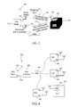
- aircraft manufacturing and service method 100 may include specification and design 102 of aircraft 200 and material procurement 104.
- aircraft 200 During production, component and subassembly manufacturing 106 and system integration 108 of aircraft 200 takes place. Thereafter, aircraft 200 may go through certification and delivery 110 in order to be placed in service 112. While in service by a customer, aircraft 200 is scheduled for routine maintenance and service 114 (which may also include modification, reconfiguration, refurbishment, and so on).
- Each of the processes of aircraft manufacturing and service method 100 may be performed or carried out by a system integrator, a third party, and/or an operator (e.g., a customer).
- a system integrator may include, without limitation, any number of aircraft manufacturers and major-system subcontractors
- a third party may include, for example, without limitation, any number of venders, subcontractors, and suppliers
- an operator may be an airline, leasing company, military entity, service organization, and so on.
- aircraft 200 produced by aircraft manufacturing and service method 100 may include airframe 202 with a plurality of systems 204 and interior 206.
- systems 204 include one or more of propulsion system 208, electrical system 210, hydraulic system 212, and environmental system 214. Any number of other systems may be included in this example.
- Apparatus and methods embodied herein may be employed during any one or more of the stages of aircraft manufacturing and service method 100.
- components or subassemblies corresponding to component and subassembly manufacturing 106 may be fabricated or manufactured in a manner similar to components or subassemblies produced while aircraft 200 is in service.
- one or more apparatus embodiments, method embodiments, or a combination thereof may be utilized during component and subassembly manufacturing 106 and system integration 108, for example, without limitation, by substantially expediting assembly of or reducing the cost of aircraft 200.
- one or more of apparatus embodiments, method embodiments, or a combination thereof may be utilized while aircraft 200 is in service, for example, without limitation, to maintenance and service 114 may be used during system integration 108 and/or maintenance and service 114 to determine whether parts may be connected and/or mated to each other.
- FIG. 3 is a simple block diagram of a passive RFID system 300.
- System 300 includes an RFID reader 310 and at least one passive RFID tag 320 which is generally affixed to an item 324 whose existence and/or location within a particular area is to be verified.
- RFID reader 310 includes a transmission antenna 330 and a receiving antenna 340.
- antennas 330 and 340 may be a single antenna that is multiplexed.
- RFID reader 310 transmits a signal 350 that is generally at a specific frequency, the frequency being within a range that will cause the RFID tag 320 to resonate.
- Signal 350 is sometimes referred to as an activation signal.
- Signal 350 may be a modulated signal that carries data, such as an amplitude modulated signal at a carrier frequency.
- Signal 350 is transmitted at a specific power as well.
- RFID tag 320 when RFID tag 320 is caused to resonate by receiving signal 350 at an antenna 360 that is associated with RFID tag 320, it will in tum begin to transmit a signal 370, that can be received by the receiving antenna 340.
- Signal 370 includes data which can be interpreted by RFID reader 310. As shown in Figure 3 , the signal 370 may be an amplitude shift keying (ASK) modulated signal, a phase shift keying (PSK) modulated signal, or other type of modulated signal.
- ASK amplitude shift keying
- PSK phase shift keying
- RFID reader 310 is programmed such that receipt of signal 370 indicates one or more of an existence, location, or other identifier for item 324.
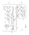
- FIG. 4 is a block diagram of a passive RFID system 400 that incorporates a distributed antenna system (DAS).
- System 400 includes an RFID reader 410 whose transmission output 412 and receiver input 414 are coupled to a DAS processing function 420 which interfaces transmission output 412 and receiver input 414 to an antenna hub 430.
- Antenna hub 430 is communicatively coupled to antenna units 440, 442, and 444.
- any one, or multiple of antenna units 440, 442, and 444 may transmit signals to and receive signals from RFID tag 450 on item 452.
- the received power is increased by up to 10 dB for an equivalent transmitted power.
- DAS and the elimination of nulls can improve read accuracy to 100 %, as well as increasing the read rate and increasing the receiver power by a total of 15 dB. Such improvements lead to a ten fold increase in passive RFID tag read range, and lead to a ten fold increase in the velocity that can be measured for mobile passive RFID tags.
- the incorporation of a DAS may provide a capability to transmit signals to and receive signals from a plurality of RFID tags 450 while the RFID reader is maintained in a single location. In many current applications, the RFID reader must be moved along a defined path so that signals emanating therefrom come into contact with RFID tags with sufficient power to cause the passive tag to resonate.
- Figure 4 and subsequent figures utilize an example of three antenna units within a distributed antenna system
- the number of antenna units within a DAS is dependent upon the area to be covered by the antenna patterns, the transmission patterns of the antenna units themselves (e.g., the size and shape of nulls in the individual transmission patterns), and the available locations for deployment of antenna units.
- Figure 5 is an illustration of transmission signals of antenna units 440, 442, and 444 deployed, for example, within an aircraft cabin or cargo area 500. Components utilized in Figure 5 that could be common with those shown in Figure 4 are illustrated usmg the same reference numerals. In embodiments, an antenna unit configuration, or distribution, could be deployed that provides coverage for one or more of an aircraft cabin, a cargo area, an aircraft mechanical equipment area, a wing or any other defined area that is associated with an aircraft.
- Figure 5 is provided to illustrate that antenna units 440, 442, and 444 each have a corresponding transmission pattern (460, 462, and 464 respectively) within which an RFID tag therein will be caused to resonate when the specific antenna unit is transmitting.
- Figure 5 further illustrates that antenna units may be deployed such that an entire area may be covered by the transmission patterns so that all RFID tags within the area may be activated by a transmission from at least one of the antenna units.
- antenna units 440, 442, and 444 may be placed so that the transmission patterns 460, 462, and 464 overlap to ensure coverage of an entire area.
- Figure 5 illustrates that a distributed antenna system may be deployed to provide transmission and reception capabilities for multiple communications services.
- the distributed antenna system may be utilized to support multiple of RFID communications with RFID reader 410, WiFi communications with WiFi unit 510, and cellular communications with 3G (or other) cellular communications unit 520.
- the RFID, WiFi, and cellular communications may be accomplished simultaneously through the system.
- An optical-fiber distributed antenna system employs several full duplex radio over fiber links to distribute analogue signals to a number of antenna units.
- signals are taken from an access point or base--station in the antenna switching hub 430 and used to directly control the bias current of a laser diode, resulting in light whose intensity is modulated by the RF signal.
- the optical signal is transmitted over fiber and detected by a photodiode in the antenna units 440, 442, and 444.
- the resulting RF signal is then amplified for wireless transmission.
- the uplink operates in a similar manner but in reverse such that within the antenna units 440, 442, and 444, the incoming RF signal is amplified and the resulting signal used to directly modulate a laser.
- the carrier between the antenna switching hub 430 and the antenna units 440, 442, and 444 is a single mode fiber. In one embodiment, the carrier between the antenna switching hub 430 and the antenna units 440, 442, and 444 is a multimode fiber.
- the analogue modulation of transverse-mode laser transmitters allows the use of high frequencies (beyond the 3dB multi-mode bandwidth) to transmit information.
- the antenna units 440, 442, and 444 convert the optical signal to RF for wireless transmission.
- the carrier between the antenna switching hub 430 and the antenna units 440, 442, and 444 is a coaxial cable.
- antenna units 440, 442, and 444 amplify the RF signal prior to transmission.
- total output power can be reduced and therefore the dynamic range of the optical links between the antenna switching hub 430 and antenna units 440, 442, and 444 can be reduced.
- Certain distributed antenna systems may incorporate optical fiber communications and therefore provide a wide bandwidth that is capable of supporting all current communications services.
- the addition of an RFID function to such a common infrastructure overcomes many of the installation difficulties associated with the introduction of new "systems" on an aircraft (i.e., weight, space, cost, and increased fuel consumption because of weight).
- an accurate real time locating system that includes low cost, passive RFID tags onboard an aircraft enabled by a distributed antenna system (DAS) can locate, for example, passengers, baggage, confirm a full compliment of life vests, maintain an inventory of portable onboard items, and enable physical position location mapping of totally wireless electronic devices (sensors) to logical addresses for cabin services.
- DAS distributed antenna system
- An RFID real time locating system can also be used in an aircraft in-flight entertainment system that includes a daisy chain of seat electronic boxes (SEBs) spaced throughout the aircraft, as an alternative to identifying a location of each SEB based upon passing of the registration token among the plurality of wired SEBs.
- SEBs seat electronic boxes
- Aircraft 600 includes a main cabin 610 and a cargo compartment 620.
- a universal wireless distribution system 630 is communicatively coupled to the airplane communications network 640.
- the universal wireless distribution system 630 performs the antenna hub function described with respect to preceding figures. As such, it is communicatively coupled to RFID reader 650 and communications device 660.
- Communications device 660 represents the interface for WiFi and/or cellular communications.
- universal wireless distribution system 630 is coupled to antenna units 670, 672, and 674 which make up the DAS for the main cabin 610.
- antenna units 670, 672, and 674 provide a transmission capability to activate passive RFID tags 680, 682, 684, and 686. Respectively, these tags are coupled to mobile wireless devices 690, low-power wireless devices 692, passengers 694, and life vests 696. These representative examples of RFID tag deployment should be understood to be examples only. In certain embodiments, passengers may not be matched with an RFID tag, and other devices with an aircraft cabin may have an RFID tag attached thereto. In other words, which items are deployed with RFID tags are application specific. However, in any application, the tags may all be activated through the distributed antenna system of antenna units 670, 672, and 674, and the supporting components for such antenna units as is herein described. It should further be understood that there may be multiple of the individual items (e.g., life vests 696) each of which has a passive RFID tag attached thereto.
- Universal wireless distribution system 630 is also coupled to a remote distributed antenna system controller 700, to which antenna units 710, 712, and .714 are coupled.
- Remote distributed antenna system controller 700 and antenna units 710, 712, and 714 are utilized to track RFID tags 720, 722, and 724 placed on items within cargo compartment 620.
- the respective items include a low-power wireless device 730, a mobile wireless device 732, and luggage 734.
- these items are examples only, and many different items within main cabin 610, cargo compartment 620, and other areas of an aircraft may be tagged with a passive RFID tag and caused to be activated by a distributed antenna system similar to the ones shown in Figure 6 .
- Other remote DASs within other areas of an aircraft would also be communicatively coupled to, for example, RFID reader 650 and communications device 660 through universal wireless distribution system 630.
- the universal wireless distribution system 630 serves as a gateway between the wired airplane network 640 and the wireless airplane network by combining all wireless signals supporting a plurality of wireless systems, such as passenger internet connectivity, mobile phones, and distributed airplane functions.
- the UWDS 630 outputs the combined signal via the distributed antenna system (DAS), which in one embodiment constitutes a leaky feeder coaxial antenna.
- DAS distributed antenna system
- a leaky coaxial distribution system offers an alternative to a distributed antenna system to support onboard aircraft communication services, the leaky coaxial distribution system also supports passive RFID real time location systems onboard aircraft when radiated through distributed antenna units.
- the RDAS 700 is one embodiment of a wireless data concentrator, which may host airplane functions, or as shown, serve as wireless bridges for one or more low-power wireless devices (LWDs). These wireless data concentrators also provide extended wireless network coverage for supplicants outside the wireless network coverage area of the UWDS, such as outside the fuselage or in another airplane compartment.
- the wireless data concentrators form a wireless multi-hop relay network to increase availability, reliability, and network coverage.
- a plurality of mobile wireless devices such as notebook computers and mobile phones (and MWDs 690 and 732), that are within wireless network coverage area of the UWDS 630 connect directly to the UWDS, or to one of the wireless data concentrators if outside the UWDS coverage area.
- a plurality of low power wireless devices such as wireless sensors or switches, also connect to the network through the wireless data concentrators.
- leaky coaxial cables provide an alternative approach to a distributed antenna systems.
- a leaky coax cable is very similar to normal coaxial cable in its construction. However, one difference is in the outer conductor of the cable.
- Normal coaxial cables use outer conductor shields that are designed to minimize RF leakage.
- the outer conductor of a typical leaky coaxial cable includes holes or openings formed in the outer conductor to allow a controlled amount of RF signal from the center conductor to leak out into the surrounding environment. Although most of the signal still travels through the cable, on the center conductor, these openings allow the signal to radiate out from the cable or currents to travel on the outer conductor surface, creating an RF field around the cable.
- Figure 7 is an illustration of one embodiment of a deployment within an aircraft 600 of a first leaky coaxial cable 800 for transmission and a second leaky coaxial cable 802 for reception configured to operate as a distributed antenna system (DAS). Similar to the embodiment depicted in Figure 6 , a remote DAS 700 is also included that is utilized to communicate with a second plurality of RFID tags 720, 722, and 724 via additional leaky coaxial cables 810 and 812.
- the universal wireless distribution system 630 is communicatively coupled to the airplane communications network 640 in the same manner as described above with respect to Figure 6 .
- universal wireless distribution system 630 is coupled to a single leaky coaxial cable with frequencies or alternate means to prevent interference between uplink and downlink signals.
- separate transmission and reception coaxial cable antenna units (800, 802, 810, and 812) are utilized.
- multiple transmission points 820 and 830 are generated.
- multiple reception points 820 and 830 are generated.
- These transmission and reception points generally operate as the antenna units described above, and may be considered for purposes herein as "virtual antenna units", except that it is possible to easily generate additional transmission and reception points with the leaky coaxial cable as each point requires only an opening in the outer conductor of the coaxial cable. Adding additional antenna units such as those described with respect to Figure 6 requires the space needed to house such units. In certain applications, such space is a premium.
- the preceding figures are related to onboard passive RFID systems that include a distributed antenna system (DAS) with individual antenna unit locations optimized to reduce nulls and increase received signal strengths from the passive RFID tags.
- DAS distributed antenna system
- leaky coaxial cable is utilized which in effect simulates a distributed antenna system.
- improvement in RFID read rates and accuracy can be achieved by extending the range of the RFID readers thereby increasing the received power by 10 dB for an equivalent transmitted power.
- areas of antenna nulls can be reduced or eliminated in both the DAS and leaky coaxial cable embodiments. DAS and the elimination of nulls can improve read accuracy to 100 %, further increases the read rate, and increasing receiver power by a total of 15 dB.
- the combination of the preceding factors may result in an up to ten fold increase in passive RFID tag read range, and enable velocity measurements for mobile passive RFID tags.
- the improvements for the passive RFID over DAS RFID receiver system arise when it is compared with a conventional RFID receiver system.
- the described RFID systems also allow for the identifying of items that include one or more passive RFID tags in a radio fingerprinted cabin.
- the incorporation of a DAS allows for the utilization of multiple antenna locating techniques to improve the absolute locating accuracy of the various passive RFID tags dispersed within an aircraft.
- the RFID systems provide a capability to provide a location of a passive RFID tag to within a single seat or seat group within an aircraft cabin. In dimension, a location can therefore be provided for a passive RFID tag to within about +/- 0.5 meter.
- Further incorporation of a DAS also allows for the remote integration of other onboard HF, UHF, and SHF data services such as WiFi and cell phone over a common DAS infrastructure.
- Prior locating systems are based on active RFID tags that are 100 times more costly per tag, require tag batteries, and have limited accuracy and resolution capabilities.
- prior approaches to the mapping of physical locations for totally wireless devices such as reading light control buttons in seat arms, use elaborate wired token bus passing schemes to map overhead reading light locations to passenger light control buttons on seat arms.
- the embodiments illustrate the use of low cost, passive RFID tags to locate immobile items for inventory, maintain a position of mobile passengers, for example, with RFID tags printed on boarding passes, and for associating baggage with travel itineraries with passive RFID tag tagged luggage.
- the described embodiments are useful for the identifying of items in a radio fingerprinted aircraft cabin, and incorporate multiple antenna locating techniques to improve the absolute locating accuracy of passive RFID tags to within a single seat or seat group (e.g., plus or minus one-half meter).
- the described systems also are useful for the remote integration of other onboard wireless data services such as WiFi and cell phone over a common DAS infrastructure.
Landscapes
- Engineering & Computer Science (AREA)
- Physics & Mathematics (AREA)
- Health & Medical Sciences (AREA)
- Toxicology (AREA)
- General Physics & Mathematics (AREA)
- Artificial Intelligence (AREA)
- Computer Vision & Pattern Recognition (AREA)
- Theoretical Computer Science (AREA)
- Electromagnetism (AREA)
- General Health & Medical Sciences (AREA)
- Computer Networks & Wireless Communication (AREA)
- Mobile Radio Communication Systems (AREA)
- Near-Field Transmission Systems (AREA)
Description
- The field of the invention relates generally to the tracking and inventory of items on an aircraft, and more specifically, to methods and systems for real time RFID locating onboard an aircraft.
- Existing inventory and tracking solutions based on active RFID and WiFi use signal strength measurements and time difference of arrival algorithms to determine location coordinates. More recently, broadband wireless location beacon signals have been used to overcome areas of poor WiFi coverage. One system uses a network of RFID readers and their dedicated processors and software to locate tags among a dedicated network of RFID readers. Another solution uses software controlled smart antennas to steer beams, and perform signal acquisition and source location using an array of elements, an array controller, plus an RFID reader module, weighing 50 to 85 lbs per antenna. Still another system requires placement of transmitters near tags and sophisticated signal processing to locate multiple tags with its long range phased array receiver.
- Such systems have disadvantages and other limitations when applied to an aircraft environment. Specifically, such complex systems utilize components having significant weight or require significant computing resources for signal processing, which is always a concern or limitation in the aircraft environment. Although simpler system solutions can utilize active RFID tags, these active RFID tags are 1000 times more expensive per tag than passive RFID tags. Active RFID tags are at least one inch square in size, while passive RFID tags can be up to 1000 times smaller. Active RFID tags read by active RFID readers do have up to 100 times greater range than do passive RFID tags, when read by single passive RFID readers with single local transmit and receive antennas. However, the active RFID tags require tag batteries, and have very limited accuracy and resolution capabilities.
- RFID systems that incorporate the less expensive passive RFID tags are complex, dedicated tracking solutions, with bulky and heavy smart antennas, as described above. Each tracking and communication solution requires a separate, dedicated wiring infrastructure. Digital networks of RFID tag readers have limited capabilities to estimate time difference of arrival for RFID tag location finding due to delays embedded in the digital network system solutions. Such delays are sometimes resolved through an array of networked short range passive RFID readers located at choke points though which the short range RFID tags pass to estimate real time locations of RFID tags.
- There are aircraft applications that utilize active RFID technology, for example, to track aircraft parts and high value assets. Such applications are used primarily for intelligent inventory, and not location tracking.
-
US 200710001809 -
EP 1478106 describes a cellular communication system in an aircraft. -
KR20080015974 - In one aspect, an aircraft communications and item tracking system according to claim 1 is provided. The system includes an RFID reader and a communications device located at fixed locations within the aircraft, a plurality of passive RFID tags operable for association with items within the aircraft, and a distributed antenna system comprising a plurality of individual transmission and reception points and a wireless distribution system. The wireless distribution system is communicatively coupled to an aircraft communications network. The transmission and reception points are communicatively coupled to the wireless distribution system and dispersed about the aircraft such that the plurality of RFID tags within the aircraft may be activated by signals output by at least one of the transmission points. The RFID reader and communications device are communicatively coupled to the wireless distribution system. The distributed antenna system is operable for transmission and reception of signals associated with the RFID reader and RFID tags. The distributed antenna system is further operable for transmission and reception of signals associated with the communications device.
- In another aspect, a method according to claim 9 is provided for tracking items on an aircraft where each item to be tracked is associated with at least one passive RFID tag. The method includes outputting an activation signal from a stationary RFID reader within the aircraft, the signal operable for activation of passive RFID tags, routing the activation signal from the RFID reader for transmission through transmission points of a distributed antenna system, individual transmission and reception points of the distributed antenna system dispersed within the aircraft, the distributed antenna system providing a communications capability for at least one other communications system, receiving, via the dispersed reception points, signals generated by the passive RFID tags activated by the transmitted activation signal, and routing the received signals through the distributed antenna system for interpretation by the RFID reader. The method provides for the opportunity to interrogate passive RFID tags to determine a component inventory of an aircraft, and enable physical position location mappmg of totally wireless electronic devices (sensors) to logical addresses for cabin services. Further, the method provides for the conversion of an optical signal from wireless distribution system to RF for wireless transmission; which acts as an optical link between the wireless distribution system and the antennae units.
- In still another aspect, an aircraft according to claim 13 is provided. The aircraft includes a plurality of wireless communications devices deployed within the aircraft including at least one passive tag RFID reader, a wireless distribution system operative as a communications access point for the plurality of wireless communications devices, and a plurality of individual transmission and reception points communicatively coupled to the wireless distribution system. The wireless distribution system is operative to integrate a plurality of communications services over a common infrastructure. At least one of the communications services is associated with the at least one passive tag RFID reader and the transmission and reception points are dispersed within the aircraft such that a transmission pattern associated with the transmission and reception points is provided that allows for communications with passive RFID devices deployed within the aircraft.
- The features, functions, and advantages that have been discussed can be achieved independently in various embodiments of the present invention or may be combined in yet other embodiments further details of which can be seen with reference to the following description and drawings.
-
-
Figure 1 is a flow diagram of an aircraft production and service methodology. -
Figure 2 is a block diagram of an aircraft. -
Figure 3 is a block diagram of a passive RFID system. -
Figure 4 is a block diagram of a passive RFID system that incorporates a distributed antenna system (DAS). -
Figure 5 is an illustration of transmission signals from antenna units deployed within an aircraft cabin or cargo area. -
Figure 6 is a depiction of a distributed antenna system (DAS) and a remote DAS deployed within an aircraft and utilized to communicate with a plurality of RFID tags. -
Figure 7 is a depiction of a distributed antenna system (DAS) fabricated using leaky coaxial cable, deployed within an aircraft, and utilized to communicate with a plurality of RFID tags. - Accurate, real time locating (RTLS) of low cost passive RFID tags onboard an aircraft provide an ability to locate, for example, passengers, baggage, confirm a full complement of life vests, maintain an inventory of portable onboard items, and enable physical position location mapping of totally wireless electronic devices (e.g. sensors) to logical network addresses for cabin services.
- Embodiments are directed to an onboard passive RFID system based on a distributed antenna system (DAS) optimized to reduce nulls and increase received signal strengths throughout an aircraft. Such a system enables the identifying of items in a radio fingerprinted cabin, multi-antenna locating techniques to improve the absolute locating accuracy of passive RFID tags to within a single seat or seat group in one example. In addition, the utilization of the DAS provides a broadband system which allows a wide range of wireless communication services to be transmitted over a single distribution infrastructure. Incorporation of the DAS therefore allows remote integration of other onboard wireless data services such as WiFi and cell phone over such a common infrastructure. With such a system, simultaneous wireless communications and RFID coverage capabilities can be provided.
- More generally, the described embodiments relate to the location of passive RFID tagged items in an aircraft cabin and cargo hold for inventory control of immobile items, mapping of physical location of totally wireless electronic devices to logical network addresses, and tracking of mobile passengers for purposes of associating those passengers with their mobile baggage and travel itineraries.
- In embodiments, the passive RFID systems referred to herein refer to RFID tags that operate within a 900MHz band. In such embodiments, a high power RF carrier in this band is utilized to provide power to the tags, and backscatter modulation is used for tag to reader communications, thereby allowing passive RFID tags to be read at farther ranges.
- However, implementing a UHF real time locating system (RTLS) within an aircraft's reflective environment is not comparable to an RTLS system operating in an open environment. Specifically, RTLS performance within an aircraft environment, for the intended applications, includes achieving an accuracy of about +/- 0.5m. Such accuracy supports several applications where pinpoint location down to a single seat or seat-group is needed. Moreover, the density of nulls due to multipath RF propagation in a closed metal or composite aircraft tube is expected to be very different from RF propagation in an open office environment. Further complicating matters, for UHF-based RFID operation on global mobile platforms, the diversity of regulations (such as frequency and power) in the UHF band in various locales must be considered; while still meeting RTLS performance (accuracy & read-rate) goals in all cases. Simply put, certain countries have stringent power transmission limits within the UHF band.
- Referring more particularly to the drawings, embodiments of the disclosure may be described in the context of aircraft manufacturing and
service method 100 as shown inFigure 1 and anaircraft 200 as shown inFigure 2 . During pre-production, aircraft manufacturing andservice method 100 may include specification anddesign 102 ofaircraft 200 andmaterial procurement 104. - During production, component and
subassembly manufacturing 106 andsystem integration 108 ofaircraft 200 takes place. Thereafter,aircraft 200 may go through certification anddelivery 110 in order to be placed inservice 112. While in service by a customer,aircraft 200 is scheduled for routine maintenance and service 114 (which may also include modification, reconfiguration, refurbishment, and so on). - Each of the processes of aircraft manufacturing and
service method 100 may be performed or carried out by a system integrator, a third party, and/or an operator (e.g., a customer). For the purposes of this description, a system integrator may include, without limitation, any number of aircraft manufacturers and major-system subcontractors; a third party may include, for example, without limitation, any number of venders, subcontractors, and suppliers; and an operator may be an airline, leasing company, military entity, service organization, and so on. - As shown in
Figure 2 ,aircraft 200 produced by aircraft manufacturing andservice method 100 may includeairframe 202 with a plurality ofsystems 204 and interior 206. Examples ofsystems 204 include one or more ofpropulsion system 208,electrical system 210,hydraulic system 212, andenvironmental system 214. Any number of other systems may be included in this example. - Although an aerospace example is shown, the principles of the disclosure may be applied to other industries, such as the automotive industry.
- Apparatus and methods embodied herein may be employed during any one or more of the stages of aircraft manufacturing and
service method 100. For example, without limitation, components or subassemblies corresponding to component andsubassembly manufacturing 106 may be fabricated or manufactured in a manner similar to components or subassemblies produced whileaircraft 200 is in service. - Also, one or more apparatus embodiments, method embodiments, or a combination thereof may be utilized during component and
subassembly manufacturing 106 andsystem integration 108, for example, without limitation, by substantially expediting assembly of or reducing the cost ofaircraft 200. Similarly, one or more of apparatus embodiments, method embodiments, or a combination thereof may be utilized whileaircraft 200 is in service, for example, without limitation, to maintenance andservice 114 may be used duringsystem integration 108 and/or maintenance andservice 114 to determine whether parts may be connected and/or mated to each other. - The description of the different advantageous embodiments has been presented for purposes of illustration and description, and is not intended to be exhaustive or limited to the embodiments in the form disclosed. Many modifications and variations will be apparent to those of ordinary skill in the art. Further, different advantageous embodiments may provide different advantages as compared to other advantageous embodiments. The embodiment or embodiments selected are chosen and described in order to best explain the principles of the embodiments, the practical application, and to enable others of ordinary skill in the art to understand the disclosure for various embodiments with various modifications as are suited to the particular use contemplated.
-
Figure 3 is a simple block diagram of apassive RFID system 300.System 300 includes anRFID reader 310 and at least onepassive RFID tag 320 which is generally affixed to anitem 324 whose existence and/or location within a particular area is to be verified. As shown,RFID reader 310 includes atransmission antenna 330 and a receivingantenna 340. In embodiments,antennas RFID reader 310 transmits asignal 350 that is generally at a specific frequency, the frequency being within a range that will cause theRFID tag 320 to resonate.Signal 350 is sometimes referred to as an activation signal.Signal 350 may be a modulated signal that carries data, such as an amplitude modulated signal at a carrier frequency.Signal 350 is transmitted at a specific power as well. As is known, whenRFID tag 320 is caused to resonate by receivingsignal 350 at anantenna 360 that is associated withRFID tag 320, it will in tum begin to transmit asignal 370, that can be received by the receivingantenna 340.Signal 370 includes data which can be interpreted byRFID reader 310. As shown inFigure 3 , thesignal 370 may be an amplitude shift keying (ASK) modulated signal, a phase shift keying (PSK) modulated signal, or other type of modulated signal.RFID reader 310 is programmed such that receipt ofsignal 370 indicates one or more of an existence, location, or other identifier foritem 324. -
Figure 4 is a block diagram of apassive RFID system 400 that incorporates a distributed antenna system (DAS).System 400 includes anRFID reader 410 whosetransmission output 412 andreceiver input 414 are coupled to aDAS processing function 420 which interfacestransmission output 412 andreceiver input 414 to anantenna hub 430.Antenna hub 430 is communicatively coupled toantenna units antenna units RFID tag 450 onitem 452. By utilizing the distributed antenna system, improvement in RFID read rates and accuracy can be achieved as the range of the RFID readers is extended. In one embodiment, the received power is increased by up to 10 dB for an equivalent transmitted power. In addition, areas of antenna nulls can be reduced or eliminated. DAS and the elimination of nulls can improve read accuracy to 100 %, as well as increasing the read rate and increasing the receiver power by a total of 15 dB. Such improvements lead to a ten fold increase in passive RFID tag read range, and lead to a ten fold increase in the velocity that can be measured for mobile passive RFID tags. Further, the incorporation of a DAS may provide a capability to transmit signals to and receive signals from a plurality ofRFID tags 450 while the RFID reader is maintained in a single location. In many current applications, the RFID reader must be moved along a defined path so that signals emanating therefrom come into contact with RFID tags with sufficient power to cause the passive tag to resonate. WhileFigure 4 and subsequent figures utilize an example of three antenna units within a distributed antenna system, those skilled in the art that the number of antenna units within a DAS is dependent upon the area to be covered by the antenna patterns, the transmission patterns of the antenna units themselves (e.g., the size and shape of nulls in the individual transmission patterns), and the available locations for deployment of antenna units. -
Figure 5 is an illustration of transmission signals ofantenna units cargo area 500. Components utilized inFigure 5 that could be common with those shown inFigure 4 are illustrated usmg the same reference numerals. In embodiments, an antenna unit configuration, or distribution, could be deployed that provides coverage for one or more of an aircraft cabin, a cargo area, an aircraft mechanical equipment area, a wing or any other defined area that is associated with an aircraft. - In one aspect,
Figure 5 is provided to illustrate thatantenna units Figure 5 further illustrates that antenna units may be deployed such that an entire area may be covered by the transmission patterns so that all RFID tags within the area may be activated by a transmission from at least one of the antenna units. Specifically and as shown,antenna units transmission patterns Figure 5 illustrates that a distributed antenna system may be deployed to provide transmission and reception capabilities for multiple communications services. More specifically, the distributed antenna system may be utilized to support multiple of RFID communications withRFID reader 410, WiFi communications withWiFi unit 510, and cellular communications with 3G (or other)cellular communications unit 520. The RFID, WiFi, and cellular communications may be accomplished simultaneously through the system. - An optical-fiber distributed antenna system (DAS) employs several full duplex radio over fiber links to distribute analogue signals to a number of antenna units. For the downlink, signals are taken from an access point or base--station in the
antenna switching hub 430 and used to directly control the bias current of a laser diode, resulting in light whose intensity is modulated by the RF signal. The optical signal is transmitted over fiber and detected by a photodiode in theantenna units antenna units antenna switching hub 430. In one embodiment, the carrier between theantenna switching hub 430 and theantenna units antenna switching hub 430 and theantenna units antenna units antenna switching hub 430 and theantenna units antenna units antenna switching hub 430 andantenna units - Certain distributed antenna systems may incorporate optical fiber communications and therefore provide a wide bandwidth that is capable of supporting all current communications services. In the aircraft application, the addition of an RFID function to such a common infrastructure overcomes many of the installation difficulties associated with the introduction of new "systems" on an aircraft (i.e., weight, space, cost, and increased fuel consumption because of weight).
- As mentioned above, an accurate real time locating system that includes low cost, passive RFID tags onboard an aircraft enabled by a distributed antenna system (DAS) can locate, for example, passengers, baggage, confirm a full compliment of life vests, maintain an inventory of portable onboard items, and enable physical position location mapping of totally wireless electronic devices (sensors) to logical addresses for cabin services.
- An RFID real time locating system can also be used in an aircraft in-flight entertainment system that includes a daisy chain of seat electronic boxes (SEBs) spaced throughout the aircraft, as an alternative to identifying a location of each SEB based upon passing of the registration token among the plurality of wired SEBs.
- Turning now to
Figure 6 , one embodiment of a deployment within anaircraft 600 of a distributed antenna system (DAS) and a remote DAS utilized to communicate with a plurality of RFID tags is depicted.Aircraft 600 includes amain cabin 610 and acargo compartment 620. In the illustrated embodiment, a universalwireless distribution system 630 is communicatively coupled to theairplane communications network 640. The universalwireless distribution system 630 performs the antenna hub function described with respect to preceding figures. As such, it is communicatively coupled toRFID reader 650 andcommunications device 660.Communications device 660 represents the interface for WiFi and/or cellular communications. Similar to the depiction inFigure 5 , universalwireless distribution system 630 is coupled toantenna units main cabin 610. - Within the aircraft cabin,
antenna units passive RFID tags mobile wireless devices 690, low-power wireless devices 692,passengers 694, andlife vests 696. These representative examples of RFID tag deployment should be understood to be examples only. In certain embodiments, passengers may not be matched with an RFID tag, and other devices with an aircraft cabin may have an RFID tag attached thereto. In other words, which items are deployed with RFID tags are application specific. However, in any application, the tags may all be activated through the distributed antenna system ofantenna units - Universal
wireless distribution system 630 is also coupled to a remote distributedantenna system controller 700, to whichantenna units antenna system controller 700 andantenna units cargo compartment 620. In the illustrated example, the respective items include a low-power wireless device 730, amobile wireless device 732, andluggage 734. Again, these items are examples only, and many different items withinmain cabin 610,cargo compartment 620, and other areas of an aircraft may be tagged with a passive RFID tag and caused to be activated by a distributed antenna system similar to the ones shown inFigure 6 . Other remote DASs within other areas of an aircraft would also be communicatively coupled to, for example,RFID reader 650 andcommunications device 660 through universalwireless distribution system 630. - In one embodiment, the universal
wireless distribution system 630 serves as a gateway between thewired airplane network 640 and the wireless airplane network by combining all wireless signals supporting a plurality of wireless systems, such as passenger internet connectivity, mobile phones, and distributed airplane functions. - The
UWDS 630 outputs the combined signal via the distributed antenna system (DAS), which in one embodiment constitutes a leaky feeder coaxial antenna. Since a leaky coaxial distribution system offers an alternative to a distributed antenna system to support onboard aircraft communication services, the leaky coaxial distribution system also supports passive RFID real time location systems onboard aircraft when radiated through distributed antenna units. - The
RDAS 700 is one embodiment of a wireless data concentrator, which may host airplane functions, or as shown, serve as wireless bridges for one or more low-power wireless devices (LWDs). These wireless data concentrators also provide extended wireless network coverage for supplicants outside the wireless network coverage area of the UWDS, such as outside the fuselage or in another airplane compartment. In embodiments, the wireless data concentrators form a wireless multi-hop relay network to increase availability, reliability, and network coverage. As a result, a plurality of mobile wireless devices, such as notebook computers and mobile phones (andMWDs 690 and 732), that are within wireless network coverage area of theUWDS 630 connect directly to the UWDS, or to one of the wireless data concentrators if outside the UWDS coverage area. In embodiments, a plurality of low power wireless devices, such as wireless sensors or switches, also connect to the network through the wireless data concentrators. - As illustrated in
Figure 7 , leaky coaxial cables provide an alternative approach to a distributed antenna systems. A leaky coax cable is very similar to normal coaxial cable in its construction. However, one difference is in the outer conductor of the cable. Normal coaxial cables use outer conductor shields that are designed to minimize RF leakage. In contrast, the outer conductor of a typical leaky coaxial cable includes holes or openings formed in the outer conductor to allow a controlled amount of RF signal from the center conductor to leak out into the surrounding environment. Although most of the signal still travels through the cable, on the center conductor, these openings allow the signal to radiate out from the cable or currents to travel on the outer conductor surface, creating an RF field around the cable. - For either coupled-mode or radiated mode cable, a ray trace model that represents the cable as a sequence of "fluorescent-bulb" elements, each of which radiates diffusely, as depicted in
Figure 7 , with a Lambert's-law radiation pattern is found to work well. The performance of leaky coaxial cable as a transmission and reception device depends on the environment in which it is installed. There are differences between coupling effects and insertion loss between and indoor and outdoor environments, and whether the leaky coaxial cable is laid in a rich scattering environment or a barren one. It is contemplated that RFID location methods demonstrated for distributed antenna systems will be tailored to the coupled mode characteristics for leaky coax cables in different environments. -
Figure 7 is an illustration of one embodiment of a deployment within anaircraft 600 of a first leakycoaxial cable 800 for transmission and a second leakycoaxial cable 802 for reception configured to operate as a distributed antenna system (DAS). Similar to the embodiment depicted inFigure 6 , aremote DAS 700 is also included that is utilized to communicate with a second plurality ofRFID tags coaxial cables wireless distribution system 630 is communicatively coupled to theairplane communications network 640 in the same manner as described above with respect toFigure 6 . In one embodiment, universalwireless distribution system 630 is coupled to a single leaky coaxial cable with frequencies or alternate means to prevent interference between uplink and downlink signals. In the illustrated embodiment, separate transmission and reception coaxial cable antenna units (800, 802, 810, and 812) are utilized. Through incorporation of the leakycoaxial cables multiple transmission points coaxial cables Figure 6 requires the space needed to house such units. In certain applications, such space is a premium. - The preceding figures are related to onboard passive RFID systems that include a distributed antenna system (DAS) with individual antenna unit locations optimized to reduce nulls and increase received signal strengths from the passive RFID tags. In other embodiments, leaky coaxial cable is utilized which in effect simulates a distributed antenna system. In embodiments, by utilizing the distributed antenna system, improvement in RFID read rates and accuracy can be achieved by extending the range of the RFID readers thereby increasing the received power by 10 dB for an equivalent transmitted power. In addition, areas of antenna nulls can be reduced or eliminated in both the DAS and leaky coaxial cable embodiments. DAS and the elimination of nulls can improve read accuracy to 100 %, further increases the read rate, and increasing receiver power by a total of 15 dB. The combination of the preceding factors may result in an up to ten fold increase in passive RFID tag read range, and enable velocity measurements for mobile passive RFID tags.
- The improvements for the passive RFID over DAS RFID receiver system arise when it is compared with a conventional RFID receiver system. The described RFID systems also allow for the identifying of items that include one or more passive RFID tags in a radio fingerprinted cabin. The incorporation of a DAS allows for the utilization of multiple antenna locating techniques to improve the absolute locating accuracy of the various passive RFID tags dispersed within an aircraft. In embodiments, the RFID systems provide a capability to provide a location of a passive RFID tag to within a single seat or seat group within an aircraft cabin. In dimension, a location can therefore be provided for a passive RFID tag to within about +/- 0.5 meter. Further incorporation of a DAS also allows for the remote integration of other onboard HF, UHF, and SHF data services such as WiFi and cell phone over a common DAS infrastructure.
- Prior locating systems are based on active RFID tags that are 100 times more costly per tag, require tag batteries, and have limited accuracy and resolution capabilities. In addition, the prior approaches to the mapping of physical locations for totally wireless devices, such as reading light control buttons in seat arms, use elaborate wired token bus passing schemes to map overhead reading light locations to passenger light control buttons on seat arms.
- One problem with such an approach is that wired connections within an aircraft translate into increased aircraft weight which is generally undesirable. Therefore the described embodiments are better than prior solutions since no wiring is required to map physical locations to logical network locations. For locating items in real time, the embodiments illustrate the use of low cost, passive RFID tags to locate immobile items for inventory, maintain a position of mobile passengers, for example, with RFID tags printed on boarding passes, and for associating baggage with travel itineraries with passive RFID tag tagged luggage.
- In summary, the described embodiments are useful for the identifying of items in a radio fingerprinted aircraft cabin, and incorporate multiple antenna locating techniques to improve the absolute locating accuracy of passive RFID tags to within a single seat or seat group (e.g., plus or minus one-half meter). The described systems also are useful for the remote integration of other onboard wireless data services such as WiFi and cell phone over a common DAS infrastructure.
- This written description uses examples to disclose various embodiments, which include the best mode, to enable any person skilled in the art to practice those embodiments, including making and using any devices or systems and performing any incorporated methods. The patentable scope is defined by the claims, and may include other examples that occur to those skilled in the art. Such other examples are intended to be within the scope of the claims if they have structural elements that do not differ from the literal language of the claims, or if they include equivalent structural elements with insubstantial differences from the literal languages of the claims.
Claims (13)
- An aircraft communications and item tracking system comprising:a RFID reader (310) located at a first fixed location within an aircraft (200);a communications device (660) located at a second fixed location within the aircraft; anda distributed antenna system comprising a plurality of individual transmission and reception points and a wireless distribution system (630), said wireless distribution system (630) being communicatively coupled to an aircraft communications network (640), said transmission and reception points being communicatively coupled to said wireless distribution system (630), said transmission and reception points being dispersed about the aircraft (200) such that a plurality of passive RFID tags (320) within the aircraft (200) may be activated by signals output by at least one of said transmission points, said RFID reader (310) and said communications device (660) being communicatively coupled to said wireless distribution system (630), said distributed antenna system being operable for transmission and reception of signals associated with said RFID reader (310) and the passive RFID tas (320), characterized by: said distributed antenna system being further operable for transmission and reception of signals associated with said communications device (660)wherein said system is configured for remote integration of onboard wireless data services associated with said communications device (660) over said distributed antenna system including at least one of a WiFi communications capability (510) and a cellular communications capability (520).
- The system according to Claim 1 wherein said distributed antenna system comprises an optical fiber communications capability.
- The system according to Claim 1 wherein said system is configured to utilize the physical locations of said transmission and reception points to map locations of wireless devices tagged with one or more of the RFID tags (320) to logical network addresses.
- The system according to Claim 1 wherein said system is configured to utilize the physical locations of said transmission and reception points to enable physical position location mapping of the passive RFID tags (320) to plus or minus one half meter.
- The system according to Claim 1 wherein said transmission and reception points are dispersed within said aircraft (200) to minimize areas of transmission nulls and increase received signal strengths throughout the aircraft (200) for a given transmission power.
- The system according to Claim 1 wherein said wireless distribution system (630) comprises a processing function (420) and an antenna hub (430), said wireless distribution system (630) being operable to interface transmission output from said RFID reader (310) and receiver input to said RFID reader (310).
- The system according to Claim 1 further comprising:a second plurality of passive RFID tags (720), (722), (724) operable for association with items within a second section of the aircraft;at least one remote distributed antenna system controller (700); anda plurality of additional transmission and reception points communicatively coupled to said at least one remote distributed antenna system controller, said at least one remote distributed antenna system controller (700) being communicatively coupled to said wireless distribution system (630), said at least one remote distributed antenna system controller and said additional transmission and reception points being operable for transmission and reception of signals associated with said RFID reader (310) and with said second plurality of passive RFID tags (720), (722), (724).
- The system according to Claim 1 wherein said transmission and reception points comprise at least one of:a plurality of antenna units; andat least one leaky coaxial cable comprising an outer conductor further comprising one or more openings within said outer conductor.
- A method for tracking items on an aircraft (200), each item to be tracked associated with at least one passive RFID tag (310), said method comprising:outputting an activation signal from a stationary RFID reader (310) within the aircraft, the signal being operable for activation of passive RFID tags (320);routing the activation signal from the RFID reader 310 for transmission through transmission points of a distributed antenna system, individual transmission and reception points of the distributed antenna system being dispersed within the aircraft, the distributed antenna system providing a communications capability for at least one other communications system;receiving, via the dispersed reception points of the distributed antenna system, signals generated by the passive RFID tags (320) activated by the transmitted activation signal;routing the received signals through the distributed antenna system for interpretation by the RFID reader (310); andintegrating onboard wireless data services for the other communications systems over the distributed antenna system including at least one of a WiFi communications capability (510) and a cellular communications capability (520).
- The method according to Claim 9 wherein routing the activation signal from the RFID reader (410) for transmission through the transmission points of a distributed antenna system comprises utilizing an optical fiber communications capability.
- The method according to Claim 9 further comprising utilizing the physical locations of the individual transmission and recepti_on points of the distributed antenna system to map locations of RFID tagged devices to logical network addresses.
- The method according to Claim 9 further comprising dispersing the individual transmission and reception points of the distributed antenna system within the aircraft to minimize areas of transmission nulls and increase strength of signals received from the passive RFID tags throughout the aircraft.
- An aircraft comprising:an aircraft communications and item tracking system, said system comprising:a RFID reader (310) located at a first fixed location within an aircraft (200);a communications device (660) located at a second fixed location within the aircraft; anda distributed antenna system comprising a plurality of individual transmission and reception points and a wireless distribution system (630),said wireless distribution system (630) being communicatively coupled to an aircraft communications network (640),said transmission and reception points being communicatively coupled to said wireless distribution system (630), said transmission and reception points being dispersed about the aircraft (200) such that a plurality of passive RFID tags (320) within the aircraft (200) may be activated by signals output by at least one of said transmission points,said RFID reader (310) and said communications device (660) being communicatively coupled to said wireless distribution system (630),said distributed antenna system being operable for transmission and reception of signals associated with said RFID reader (310) and the passive RFID tags (320),characterized by:said distributed antenna system being further operable for transmission and reception of signals associated with said communications device (660),wherein said system is configured for remote integration of onboard wireless data services associated with said communications device (660) over said distributed antenna system including at least one of a WiFi communications capability (510) and a cellular communications capability (520).
Applications Claiming Priority (2)
| Application Number | Priority Date | Filing Date | Title |
|---|---|---|---|
| US12/632,501 US10181060B2 (en) | 2009-12-07 | 2009-12-07 | Methods and systems for real time RFID locating onboard an aircraft |
| PCT/US2010/058976 WO2011071781A1 (en) | 2009-12-07 | 2010-12-03 | Methods and systems for real time rfid locating onboard an aircraft |
Publications (2)
| Publication Number | Publication Date |
|---|---|
| EP2534607A1 EP2534607A1 (en) | 2012-12-19 |
| EP2534607B1 true EP2534607B1 (en) | 2015-09-30 |
Family
ID=43533155
Family Applications (1)
| Application Number | Title | Priority Date | Filing Date |
|---|---|---|---|
| EP10793095.0A Active EP2534607B1 (en) | 2009-12-07 | 2010-12-03 | Methods and systems for real time rfid locating onboard an aircraft |
Country Status (6)
| Country | Link |
|---|---|
| US (1) | US10181060B2 (en) |
| EP (1) | EP2534607B1 (en) |
| JP (1) | JP2013512824A (en) |
| CN (2) | CN102648473A (en) |
| CA (1) | CA2792986C (en) |
| WO (1) | WO2011071781A1 (en) |
Cited By (2)
| Publication number | Priority date | Publication date | Assignee | Title |
|---|---|---|---|---|
| US11172342B2 (en) | 2017-02-14 | 2021-11-09 | Safran Passenger Innovations, Llc | Systems and methods for steering wireless network traffic within a vehicle |
| EP4187461A1 (en) * | 2021-11-29 | 2023-05-31 | Goodrich Corporation | Wireless tracking and ranging for cargo systems |
Families Citing this family (48)
| Publication number | Priority date | Publication date | Assignee | Title |
|---|---|---|---|---|
| US9590733B2 (en) * | 2009-07-24 | 2017-03-07 | Corning Optical Communications LLC | Location tracking using fiber optic array cables and related systems and methods |
| FR2956648B1 (en) * | 2010-02-23 | 2012-05-11 | Eurocopter France | OPTIMIZATION OF CONFIGURATION ASSEMBLY OF A WIRELESS NETWORK MESH OF RADIOFREQUENCY DEVICES IN AN AIRCRAFT |
| GB201006907D0 (en) * | 2010-04-26 | 2010-06-09 | Cambridge Entpr Ltd | RFID TAG interrogation systems |
| KR20110127968A (en) * | 2010-05-20 | 2011-11-28 | 엘에스산전 주식회사 | Remote control transmitter/receiver using rfid and method thereof |
| US9113234B2 (en) * | 2010-07-27 | 2015-08-18 | The Boeing Company | Wireless device association system |
| US9590761B2 (en) * | 2011-09-23 | 2017-03-07 | Commscope Technologies Llc | Detective passive RF components using radio frequency identification tags |
| US20130181867A1 (en) * | 2012-01-13 | 2013-07-18 | Rick Sturdivant | Location Determination System and Method Using Array Elements for Location Tracking |
| US9853499B2 (en) * | 2012-06-26 | 2017-12-26 | The Boeing Company | Wireless power harvesting along multiple paths in a reverberent cavity |
| CN104685849B (en) * | 2012-08-31 | 2018-05-01 | 康普技术有限责任公司 | A kind of method and system that passive RF components are detected using RFID tag |
| CN103729606B (en) * | 2012-10-11 | 2016-12-21 | 刘台华 | There is the frequency identification electronic device strengthening surface duct effect |
| KR101514066B1 (en) * | 2013-04-01 | 2015-04-21 | 자바무선기술(주) | Apparatus of clamping RFID antenna for forklift truck |
| US9147295B2 (en) | 2013-06-21 | 2015-09-29 | X-Card Holdings, Llc | Inductive coupling activation systems and methods |
| US9477865B2 (en) * | 2013-12-13 | 2016-10-25 | Symbol Technologies, Llc | System for and method of accurately determining true bearings of radio frequency identification (RFID) tags associated with items in a controlled area |
| US9755294B2 (en) | 2014-07-07 | 2017-09-05 | Symbol Technologies, Llc | Accurately estimating true bearings of radio frequency identification (RFID) tags associated with items located in a controlled area |
| US9817113B2 (en) * | 2014-10-22 | 2017-11-14 | The Boeing Company | Systems and methods for verifying a location of an item |
| CN105270643A (en) * | 2014-10-24 | 2016-01-27 | 栗中华 | Device and method for managing airplane protective articles |
| EP3067843A1 (en) * | 2015-03-09 | 2016-09-14 | BAG2GO GmbH | Method and system for identifying flight baggage |
| US9521678B2 (en) | 2015-03-12 | 2016-12-13 | The Boeing Company | Wireless data concentrators for aircraft data networks |
| US10063428B1 (en) * | 2015-06-30 | 2018-08-28 | Apstra, Inc. | Selectable declarative requirement levels |
| US9380428B1 (en) * | 2015-07-02 | 2016-06-28 | The Boeing Company | Location-based services onboard aircraft |
| US9646187B2 (en) * | 2015-07-31 | 2017-05-09 | The Boeing Company | Systems and methods for automated device pairing |
| US9661458B2 (en) * | 2015-08-03 | 2017-05-23 | The Boeing Company | Method for associating wireless sensors to physical locations |
| US9773136B2 (en) | 2015-10-19 | 2017-09-26 | Symbol Technologies, Llc | System for, and method of, accurately and rapidly determining, in real-time, true bearings of radio frequency identification (RFID) tags associated with items in a controlled area |
| US10645556B2 (en) | 2015-12-17 | 2020-05-05 | Airbus Operations Gmbh | Wireless data transmitting device and method for wireless data transmission |
| US9551780B1 (en) * | 2016-01-02 | 2017-01-24 | International Business Machines Corporation | Locating an object based on charging/response time |
| US9766621B2 (en) * | 2016-01-12 | 2017-09-19 | The Boeing Company | Aircraft information retrieval using onboard RFID tags |
| KR101746020B1 (en) * | 2016-02-26 | 2017-06-14 | 전자부품연구원 | Method, System and Apparatus for Backscattering Communication Using CSI |
| US9978011B2 (en) * | 2016-03-07 | 2018-05-22 | Astronics Advanced Electronic Systems Corp. | Network system for autonomous data collection |
| CN106203210B (en) * | 2016-06-29 | 2018-11-23 | 南京航空航天大学 | Extensive RFID system medion estimator method based on range estimation |
| US10382569B2 (en) * | 2016-08-29 | 2019-08-13 | The Boeing Company | Local positioning with communication tags |
| US10061951B2 (en) * | 2016-11-30 | 2018-08-28 | Wipro Limited | Methods and systems for localizing articles comprising passive radio frequency identification (RFID) tags |
| US10136341B2 (en) | 2017-01-03 | 2018-11-20 | Simmonds Precision Products, Inc. | Wireless data concentrator systems and methods |
| US10726218B2 (en) | 2017-07-27 | 2020-07-28 | Symbol Technologies, Llc | Method and apparatus for radio frequency identification (RFID) tag bearing estimation |
| GB201714992D0 (en) * | 2017-09-18 | 2017-11-01 | Cambridge Entpr Ltd | RFID systems |
| CN108199944B (en) * | 2017-12-15 | 2020-12-18 | 中国航空工业集团公司上海航空测控技术研究所 | Onboard cabin core system of dynamic daisy chain ring network and dynamic positioning method |
| WO2019139142A1 (en) * | 2018-01-12 | 2019-07-18 | 株式会社NejiLaw | Power receiving type information dispatching device and information dispatching system |
| US11218871B2 (en) * | 2018-04-09 | 2022-01-04 | Simmonds Precision Products, Inc. | Portable wireless communication adapter for avionics frequencies selectively enabled based on location within aircraft |
| CN109165537B (en) * | 2018-07-30 | 2021-07-30 | 太原理工大学 | Back scattering label distributed rate self-adaptive algorithm based on bit-rate-free code |
| CN109707585B (en) * | 2018-12-20 | 2020-07-07 | 浙江大学 | Laser propulsion method based on phased array control |
| US20220034727A1 (en) * | 2018-12-20 | 2022-02-03 | Schaeffler Technologies AG & Co. KG | Detection system and wind driven generator |
| US10872514B1 (en) | 2019-08-14 | 2020-12-22 | The Boeing Company | Safety system for tracking movable objects during vehicle production |
| CN110569941A (en) * | 2019-09-28 | 2019-12-13 | 东方航空技术有限公司 | RFID-based aviation life jacket management method and device |
| WO2022052056A1 (en) * | 2020-09-11 | 2022-03-17 | Oppo广东移动通信有限公司 | Symbol detection method and apparatus, and system |
| CN112698591A (en) * | 2020-11-26 | 2021-04-23 | 上海工程技术大学 | Airport boarding bridge intelligent monitoring system |
| EP4187432A1 (en) * | 2021-11-26 | 2023-05-31 | HID Textile Services SARL | System for reading rfid tags |
| US11987482B2 (en) | 2022-02-18 | 2024-05-21 | Goodrich Corporation | Aircraft cargo handling system with distributed antenna system and mobile cargo controller |
| CN114936569B (en) * | 2022-04-26 | 2023-04-14 | 南昌三瑞智能科技有限公司 | Power system integrating wireless radio frequency electronic tags and unmanned aerial vehicle |
| CN115352626A (en) * | 2022-08-17 | 2022-11-18 | 喜鹊颂人工智能科技有限公司 | Intelligent self-cruising unmanned distribution machine |
Family Cites Families (24)
| Publication number | Priority date | Publication date | Assignee | Title |
|---|---|---|---|---|
| CA2010390A1 (en) * | 1990-02-20 | 1991-08-20 | Robert Keith Harman | Open transmission line locating system |
| JP3812787B2 (en) * | 1997-11-20 | 2006-08-23 | 株式会社日立国際電気 | Optical conversion repeater amplification system |
| US6246320B1 (en) * | 1999-02-25 | 2001-06-12 | David A. Monroe | Ground link with on-board security surveillance system for aircraft and other commercial vehicles |
| US6281797B1 (en) * | 2000-04-04 | 2001-08-28 | Marconi Data Systems Inc. | Method and apparatus for detecting a container proximate to a transportation vessel hold |
| US9151692B2 (en) * | 2002-06-11 | 2015-10-06 | Intelligent Technologies International, Inc. | Asset monitoring system using multiple imagers |
| US7030760B1 (en) * | 2001-08-07 | 2006-04-18 | Seecontrol, Inc. | Method and apparatus for ensuring reliable loading of materials on aricraft and other vehicles |
| DE10210037A1 (en) * | 2002-03-07 | 2003-10-02 | Siemens Ag | Active backscatter transponder, communication system with such an and method for transmitting data with such an active backscatter transponder |
| DE10301451A1 (en) * | 2003-01-10 | 2004-07-22 | Atmel Germany Gmbh | Wireless data transmission method between base station and transponder, by modulating electromagnet waves at receiver using modulation technique based on received field strength |
| JP2004294338A (en) | 2003-03-27 | 2004-10-21 | Matsushita Electric Works Ltd | Spatial position control system |
| US20040229607A1 (en) | 2003-05-12 | 2004-11-18 | La Chapelle Michael De | Wireless communication inside shielded envelope |
| US7626505B2 (en) * | 2004-09-28 | 2009-12-01 | Visible Assets, Inc | RF tags for tracking and locating travel bags |
| US7198227B2 (en) * | 2004-06-10 | 2007-04-03 | Goodrich Corporation | Aircraft cargo locating system |
| EP1836465B1 (en) * | 2005-01-13 | 2010-03-31 | Rheinmetall Defence Electronics GmbH | Device and method for controlling the loading and/or unloading process of an aeroplane |
| US7319854B2 (en) * | 2005-04-29 | 2008-01-15 | The Boeing Company | Automatic airplane seat location mapping |
| US20070001809A1 (en) * | 2005-05-02 | 2007-01-04 | Intermec Ip Corp. | Method and system for reading objects having radio frequency identification (RFID) tags inside enclosures |
| US8005513B2 (en) * | 2006-03-16 | 2011-08-23 | Cellynx, Inc. | Cell phone signal booster |
| US7495560B2 (en) | 2006-05-08 | 2009-02-24 | Corning Cable Systems Llc | Wireless picocellular RFID systems and methods |
| US7528726B2 (en) * | 2006-05-26 | 2009-05-05 | Yeon Technologies Co., Ltd. | RFID portal array antenna system |
| US20070285239A1 (en) | 2006-06-12 | 2007-12-13 | Easton Martyn N | Centralized optical-fiber-based RFID systems and methods |
| US20070286599A1 (en) * | 2006-06-12 | 2007-12-13 | Michael Sauer | Centralized optical-fiber-based wireless picocellular systems and methods |
| KR20080015974A (en) | 2006-08-17 | 2008-02-21 | 브레인즈스퀘어(주) | Asset management system using wifi and method thereof |
| CN101589396A (en) * | 2006-11-27 | 2009-11-25 | 奥锡科斯技术有限公司 | System for product authentication and tracking |
| US8504019B2 (en) * | 2007-03-30 | 2013-08-06 | Livetv, Llc | Aircraft communications system with data memory cache and associated methods |
| US7880616B2 (en) * | 2008-06-25 | 2011-02-01 | Symbol Technologies, Inc. | Wireless data communication system having radio frequency devices, and related operating methods for disabling a transmit mode |
-
2009
- 2009-12-07 US US12/632,501 patent/US10181060B2/en active Active
-
2010
- 2010-12-03 CN CN201080055491XA patent/CN102648473A/en active Pending
- 2010-12-03 JP JP2012542227A patent/JP2013512824A/en active Pending
- 2010-12-03 CA CA2792986A patent/CA2792986C/en active Active
- 2010-12-03 WO PCT/US2010/058976 patent/WO2011071781A1/en active Application Filing
- 2010-12-03 EP EP10793095.0A patent/EP2534607B1/en active Active
- 2010-12-03 CN CN201810066519.8A patent/CN108121926B/en active Active
Cited By (2)
| Publication number | Priority date | Publication date | Assignee | Title |
|---|---|---|---|---|
| US11172342B2 (en) | 2017-02-14 | 2021-11-09 | Safran Passenger Innovations, Llc | Systems and methods for steering wireless network traffic within a vehicle |
| EP4187461A1 (en) * | 2021-11-29 | 2023-05-31 | Goodrich Corporation | Wireless tracking and ranging for cargo systems |
Also Published As
| Publication number | Publication date |
|---|---|
| CN102648473A (en) | 2012-08-22 |
| CN108121926A (en) | 2018-06-05 |
| WO2011071781A1 (en) | 2011-06-16 |
| EP2534607A1 (en) | 2012-12-19 |
| US20110133891A1 (en) | 2011-06-09 |
| US10181060B2 (en) | 2019-01-15 |
| CN108121926B (en) | 2021-09-24 |
| CA2792986A1 (en) | 2011-06-16 |
| CA2792986C (en) | 2019-06-18 |
| JP2013512824A (en) | 2013-04-18 |
Similar Documents
| Publication | Publication Date | Title |
|---|---|---|
| EP2534607B1 (en) | Methods and systems for real time rfid locating onboard an aircraft | |
| You et al. | Wireless communication aided by intelligent reflecting surface: Active or passive? | |
| Xiao et al. | UAV communications with millimeter-wave beamforming: Potentials, scenarios, and challenges | |
| JP2013512824A5 (en) | ||
| EP2974392B1 (en) | Aircraft based wireless communication system | |
| EP2940907B1 (en) | Antenna system | |
| KR101846227B1 (en) | Antenna tracking method between pilotless aircraft in realy link of datalink for video information using datalink for operation control | |
| US11222300B2 (en) | Integrated roofing accessories for unmanned vehicle navigation and methods and systems including the same | |
| CN101278443A (en) | Antenna system | |
| Alimi et al. | Performance analysis of space-air-ground integrated network (SAGIN) over an arbitrarily correlated multivariate FSO channel | |
| CN117882313A (en) | Wireless communication scenario, device for operation therein, beacon device and method for operation thereof | |
| US11860269B2 (en) | Centralized object detection sensor network system | |
| Rahmadya et al. | A framework to determine secure distances for either drones or robots based inventory management systems | |
| KR20090106450A (en) | Marine network system, its antenna assembly and communication method | |
| Siddiqui et al. | Ambient backscattering transponder with independently switchable Rx and Tx antennas | |
| CN101183431A (en) | Wireless communication system and wireless communication method | |
| Panunzio et al. | Propagation modeling inside the international space station for the automatic monitoring of astronauts by means of epidermal UHF-RFID sensors | |
| KR100923160B1 (en) | Method and Device for measuring electromagnetic wave field strength using remote controlled aircraft | |
| Sabesan et al. | Demonstration of improved passive UHF RFID coverage using optically-fed distributed multi-antenna system | |
| PL184543B1 (en) | Communication system employing a narro-flux coherent beam | |
| JP2017005670A (en) | Information communication device | |
| CN109935973B (en) | Back scattering antenna and distribution method thereof | |
| CN102790633A (en) | Transmission line and passenger information system | |
| US20230408630A1 (en) | Polarizer assisted star isolation method | |
| TR2021019879A2 (en) | Resource allocation for backscatter devices in the sparse channel using symbiotic radio |
Legal Events
| Date | Code | Title | Description |
|---|---|---|---|
| PUAI | Public reference made under article 153(3) epc to a published international application that has entered the european phase |
Free format text: ORIGINAL CODE: 0009012 |
|
| 17P | Request for examination filed |
Effective date: 20120910 |
|
| AK | Designated contracting states |
Kind code of ref document: A1 Designated state(s): AL AT BE BG CH CY CZ DE DK EE ES FI FR GB GR HR HU IE IS IT LI LT LU LV MC MK MT NL NO PL PT RO RS SE SI SK SM TR |
|
| DAX | Request for extension of the european patent (deleted) | ||
| 17Q | First examination report despatched |
Effective date: 20140207 |
|
| GRAP | Despatch of communication of intention to grant a patent |
Free format text: ORIGINAL CODE: EPIDOSNIGR1 |
|
| INTG | Intention to grant announced |
Effective date: 20150123 |
|
| GRAP | Despatch of communication of intention to grant a patent |
Free format text: ORIGINAL CODE: EPIDOSNIGR1 |
|
| INTG | Intention to grant announced |
Effective date: 20150527 |
|
| GRAS | Grant fee paid |
Free format text: ORIGINAL CODE: EPIDOSNIGR3 |
|
| GRAA | (expected) grant |
Free format text: ORIGINAL CODE: 0009210 |
|
| AK | Designated contracting states |
Kind code of ref document: B1 Designated state(s): AL AT BE BG CH CY CZ DE DK EE ES FI FR GB GR HR HU IE IS IT LI LT LU LV MC MK MT NL NO PL PT RO RS SE SI SK SM TR |
|
| REG | Reference to a national code |
Ref country code: CH Ref legal event code: EP Ref country code: GB Ref legal event code: FG4D |
|
| REG | Reference to a national code |
Ref country code: AT Ref legal event code: REF Ref document number: 752806 Country of ref document: AT Kind code of ref document: T Effective date: 20151015 |
|
| REG | Reference to a national code |
Ref country code: IE Ref legal event code: FG4D |
|
| REG | Reference to a national code |
Ref country code: DE Ref legal event code: R096 Ref document number: 602010027930 Country of ref document: DE |
|
| REG | Reference to a national code |
Ref country code: FR Ref legal event code: PLFP Year of fee payment: 6 |
|
| PG25 | Lapsed in a contracting state [announced via postgrant information from national office to epo] |
Ref country code: FI Free format text: LAPSE BECAUSE OF FAILURE TO SUBMIT A TRANSLATION OF THE DESCRIPTION OR TO PAY THE FEE WITHIN THE PRESCRIBED TIME-LIMIT Effective date: 20150930 Ref country code: GR Free format text: LAPSE BECAUSE OF FAILURE TO SUBMIT A TRANSLATION OF THE DESCRIPTION OR TO PAY THE FEE WITHIN THE PRESCRIBED TIME-LIMIT Effective date: 20151231 Ref country code: LT Free format text: LAPSE BECAUSE OF FAILURE TO SUBMIT A TRANSLATION OF THE DESCRIPTION OR TO PAY THE FEE WITHIN THE PRESCRIBED TIME-LIMIT Effective date: 20150930 Ref country code: NO Free format text: LAPSE BECAUSE OF FAILURE TO SUBMIT A TRANSLATION OF THE DESCRIPTION OR TO PAY THE FEE WITHIN THE PRESCRIBED TIME-LIMIT Effective date: 20151230 Ref country code: LV Free format text: LAPSE BECAUSE OF FAILURE TO SUBMIT A TRANSLATION OF THE DESCRIPTION OR TO PAY THE FEE WITHIN THE PRESCRIBED TIME-LIMIT Effective date: 20150930 |
|
| REG | Reference to a national code |
Ref country code: NL Ref legal event code: MP Effective date: 20150930 |
|
| REG | Reference to a national code |
Ref country code: LT Ref legal event code: MG4D |
|
| REG | Reference to a national code |
Ref country code: AT Ref legal event code: MK05 Ref document number: 752806 Country of ref document: AT Kind code of ref document: T Effective date: 20150930 |
|
| PG25 | Lapsed in a contracting state [announced via postgrant information from national office to epo] |
Ref country code: SE Free format text: LAPSE BECAUSE OF FAILURE TO SUBMIT A TRANSLATION OF THE DESCRIPTION OR TO PAY THE FEE WITHIN THE PRESCRIBED TIME-LIMIT Effective date: 20150930 Ref country code: RS Free format text: LAPSE BECAUSE OF FAILURE TO SUBMIT A TRANSLATION OF THE DESCRIPTION OR TO PAY THE FEE WITHIN THE PRESCRIBED TIME-LIMIT Effective date: 20150930 Ref country code: HR Free format text: LAPSE BECAUSE OF FAILURE TO SUBMIT A TRANSLATION OF THE DESCRIPTION OR TO PAY THE FEE WITHIN THE PRESCRIBED TIME-LIMIT Effective date: 20150930 |
|
| PG25 | Lapsed in a contracting state [announced via postgrant information from national office to epo] |
Ref country code: SK Free format text: LAPSE BECAUSE OF FAILURE TO SUBMIT A TRANSLATION OF THE DESCRIPTION OR TO PAY THE FEE WITHIN THE PRESCRIBED TIME-LIMIT Effective date: 20150930 Ref country code: EE Free format text: LAPSE BECAUSE OF FAILURE TO SUBMIT A TRANSLATION OF THE DESCRIPTION OR TO PAY THE FEE WITHIN THE PRESCRIBED TIME-LIMIT Effective date: 20150930 Ref country code: ES Free format text: LAPSE BECAUSE OF FAILURE TO SUBMIT A TRANSLATION OF THE DESCRIPTION OR TO PAY THE FEE WITHIN THE PRESCRIBED TIME-LIMIT Effective date: 20150930 Ref country code: IS Free format text: LAPSE BECAUSE OF FAILURE TO SUBMIT A TRANSLATION OF THE DESCRIPTION OR TO PAY THE FEE WITHIN THE PRESCRIBED TIME-LIMIT Effective date: 20160130 Ref country code: CZ Free format text: LAPSE BECAUSE OF FAILURE TO SUBMIT A TRANSLATION OF THE DESCRIPTION OR TO PAY THE FEE WITHIN THE PRESCRIBED TIME-LIMIT Effective date: 20150930 Ref country code: NL Free format text: LAPSE BECAUSE OF FAILURE TO SUBMIT A TRANSLATION OF THE DESCRIPTION OR TO PAY THE FEE WITHIN THE PRESCRIBED TIME-LIMIT Effective date: 20150930 Ref country code: IT Free format text: LAPSE BECAUSE OF FAILURE TO SUBMIT A TRANSLATION OF THE DESCRIPTION OR TO PAY THE FEE WITHIN THE PRESCRIBED TIME-LIMIT Effective date: 20150930 |
|
| PG25 | Lapsed in a contracting state [announced via postgrant information from national office to epo] |
Ref country code: PL Free format text: LAPSE BECAUSE OF FAILURE TO SUBMIT A TRANSLATION OF THE DESCRIPTION OR TO PAY THE FEE WITHIN THE PRESCRIBED TIME-LIMIT Effective date: 20150930 Ref country code: AT Free format text: LAPSE BECAUSE OF FAILURE TO SUBMIT A TRANSLATION OF THE DESCRIPTION OR TO PAY THE FEE WITHIN THE PRESCRIBED TIME-LIMIT Effective date: 20150930 Ref country code: PT Free format text: LAPSE BECAUSE OF FAILURE TO SUBMIT A TRANSLATION OF THE DESCRIPTION OR TO PAY THE FEE WITHIN THE PRESCRIBED TIME-LIMIT Effective date: 20160201 Ref country code: BE Free format text: LAPSE BECAUSE OF NON-PAYMENT OF DUE FEES Effective date: 20151231 Ref country code: RO Free format text: LAPSE BECAUSE OF FAILURE TO SUBMIT A TRANSLATION OF THE DESCRIPTION OR TO PAY THE FEE WITHIN THE PRESCRIBED TIME-LIMIT Effective date: 20150930 |
|
| REG | Reference to a national code |
Ref country code: DE Ref legal event code: R097 Ref document number: 602010027930 Country of ref document: DE |
|
| PG25 | Lapsed in a contracting state [announced via postgrant information from national office to epo] |
Ref country code: LU Free format text: LAPSE BECAUSE OF FAILURE TO SUBMIT A TRANSLATION OF THE DESCRIPTION OR TO PAY THE FEE WITHIN THE PRESCRIBED TIME-LIMIT Effective date: 20151203 Ref country code: MC Free format text: LAPSE BECAUSE OF FAILURE TO SUBMIT A TRANSLATION OF THE DESCRIPTION OR TO PAY THE FEE WITHIN THE PRESCRIBED TIME-LIMIT Effective date: 20150930 |
|
| REG | Reference to a national code |
Ref country code: CH Ref legal event code: PL |
|
| PLBE | No opposition filed within time limit |
Free format text: ORIGINAL CODE: 0009261 |
|
| STAA | Information on the status of an ep patent application or granted ep patent |
Free format text: STATUS: NO OPPOSITION FILED WITHIN TIME LIMIT |
|
| PG25 | Lapsed in a contracting state [announced via postgrant information from national office to epo] |
Ref country code: DK Free format text: LAPSE BECAUSE OF FAILURE TO SUBMIT A TRANSLATION OF THE DESCRIPTION OR TO PAY THE FEE WITHIN THE PRESCRIBED TIME-LIMIT Effective date: 20150930 |
|
| 26N | No opposition filed |
Effective date: 20160701 |
|
| REG | Reference to a national code |
Ref country code: IE Ref legal event code: MM4A |
|
| PG25 | Lapsed in a contracting state [announced via postgrant information from national office to epo] |
Ref country code: IE Free format text: LAPSE BECAUSE OF NON-PAYMENT OF DUE FEES Effective date: 20151203 Ref country code: CH Free format text: LAPSE BECAUSE OF NON-PAYMENT OF DUE FEES Effective date: 20151231 Ref country code: LI Free format text: LAPSE BECAUSE OF NON-PAYMENT OF DUE FEES Effective date: 20151231 |
|
| PG25 | Lapsed in a contracting state [announced via postgrant information from national office to epo] |
Ref country code: SI Free format text: LAPSE BECAUSE OF FAILURE TO SUBMIT A TRANSLATION OF THE DESCRIPTION OR TO PAY THE FEE WITHIN THE PRESCRIBED TIME-LIMIT Effective date: 20150930 |
|
| REG | Reference to a national code |
Ref country code: FR Ref legal event code: PLFP Year of fee payment: 7 |
|
| PG25 | Lapsed in a contracting state [announced via postgrant information from national office to epo] |
Ref country code: BE Free format text: LAPSE BECAUSE OF FAILURE TO SUBMIT A TRANSLATION OF THE DESCRIPTION OR TO PAY THE FEE WITHIN THE PRESCRIBED TIME-LIMIT Effective date: 20150930 |
|
| PG25 | Lapsed in a contracting state [announced via postgrant information from national office to epo] |
Ref country code: BG Free format text: LAPSE BECAUSE OF FAILURE TO SUBMIT A TRANSLATION OF THE DESCRIPTION OR TO PAY THE FEE WITHIN THE PRESCRIBED TIME-LIMIT Effective date: 20150930 Ref country code: HU Free format text: LAPSE BECAUSE OF FAILURE TO SUBMIT A TRANSLATION OF THE DESCRIPTION OR TO PAY THE FEE WITHIN THE PRESCRIBED TIME-LIMIT; INVALID AB INITIO Effective date: 20101203 Ref country code: SM Free format text: LAPSE BECAUSE OF FAILURE TO SUBMIT A TRANSLATION OF THE DESCRIPTION OR TO PAY THE FEE WITHIN THE PRESCRIBED TIME-LIMIT Effective date: 20150930 |
|
| PG25 | Lapsed in a contracting state [announced via postgrant information from national office to epo] |
Ref country code: CY Free format text: LAPSE BECAUSE OF FAILURE TO SUBMIT A TRANSLATION OF THE DESCRIPTION OR TO PAY THE FEE WITHIN THE PRESCRIBED TIME-LIMIT Effective date: 20150930 |
|
| PG25 | Lapsed in a contracting state [announced via postgrant information from national office to epo] |
Ref country code: MT Free format text: LAPSE BECAUSE OF FAILURE TO SUBMIT A TRANSLATION OF THE DESCRIPTION OR TO PAY THE FEE WITHIN THE PRESCRIBED TIME-LIMIT Effective date: 20150930 |
|
| REG | Reference to a national code |
Ref country code: FR Ref legal event code: PLFP Year of fee payment: 8 |
|
| PG25 | Lapsed in a contracting state [announced via postgrant information from national office to epo] |
Ref country code: MK Free format text: LAPSE BECAUSE OF FAILURE TO SUBMIT A TRANSLATION OF THE DESCRIPTION OR TO PAY THE FEE WITHIN THE PRESCRIBED TIME-LIMIT Effective date: 20150930 Ref country code: TR Free format text: LAPSE BECAUSE OF FAILURE TO SUBMIT A TRANSLATION OF THE DESCRIPTION OR TO PAY THE FEE WITHIN THE PRESCRIBED TIME-LIMIT Effective date: 20150930 |
|
| PG25 | Lapsed in a contracting state [announced via postgrant information from national office to epo] |
Ref country code: AL Free format text: LAPSE BECAUSE OF FAILURE TO SUBMIT A TRANSLATION OF THE DESCRIPTION OR TO PAY THE FEE WITHIN THE PRESCRIBED TIME-LIMIT Effective date: 20150930 |
|
| P01 | Opt-out of the competence of the unified patent court (upc) registered |
Effective date: 20230516 |
|
| PGFP | Annual fee paid to national office [announced via postgrant information from national office to epo] |
Ref country code: GB Payment date: 20231227 Year of fee payment: 14 |
|
| PGFP | Annual fee paid to national office [announced via postgrant information from national office to epo] |
Ref country code: FR Payment date: 20231227 Year of fee payment: 14 |
|
| PGFP | Annual fee paid to national office [announced via postgrant information from national office to epo] |
Ref country code: DE Payment date: 20231229 Year of fee payment: 14 |