JP2013502070A - Porous carbon oxide nanocomposite electrodes for high energy density supercapacitors - Google Patents
Porous carbon oxide nanocomposite electrodes for high energy density supercapacitors Download PDFInfo
- Publication number
- JP2013502070A JP2013502070A JP2012524710A JP2012524710A JP2013502070A JP 2013502070 A JP2013502070 A JP 2013502070A JP 2012524710 A JP2012524710 A JP 2012524710A JP 2012524710 A JP2012524710 A JP 2012524710A JP 2013502070 A JP2013502070 A JP 2013502070A
- Authority
- JP
- Japan
- Prior art keywords
- storage device
- carbon
- metal oxide
- mno
- electrode
- Prior art date
- Legal status (The legal status is an assumption and is not a legal conclusion. Google has not performed a legal analysis and makes no representation as to the accuracy of the status listed.)
- Pending
Links
Images


Classifications
-
- H—ELECTRICITY
- H01—ELECTRIC ELEMENTS
- H01G—CAPACITORS; CAPACITORS, RECTIFIERS, DETECTORS, SWITCHING DEVICES OR LIGHT-SENSITIVE DEVICES, OF THE ELECTROLYTIC TYPE
- H01G9/00—Electrolytic capacitors, rectifiers, detectors, switching devices, light-sensitive or temperature-sensitive devices; Processes of their manufacture
- H01G9/22—Devices using combined reduction and oxidation, e.g. redox arrangement or solion
-
- H—ELECTRICITY
- H01—ELECTRIC ELEMENTS
- H01G—CAPACITORS; CAPACITORS, RECTIFIERS, DETECTORS, SWITCHING DEVICES OR LIGHT-SENSITIVE DEVICES, OF THE ELECTROLYTIC TYPE
- H01G11/00—Hybrid capacitors, i.e. capacitors having different positive and negative electrodes; Electric double-layer [EDL] capacitors; Processes for the manufacture thereof or of parts thereof
- H01G11/22—Electrodes
- H01G11/24—Electrodes characterised by structural features of the materials making up or comprised in the electrodes, e.g. form, surface area or porosity; characterised by the structural features of powders or particles used therefor
-
- H—ELECTRICITY
- H01—ELECTRIC ELEMENTS
- H01G—CAPACITORS; CAPACITORS, RECTIFIERS, DETECTORS, SWITCHING DEVICES OR LIGHT-SENSITIVE DEVICES, OF THE ELECTROLYTIC TYPE
- H01G11/00—Hybrid capacitors, i.e. capacitors having different positive and negative electrodes; Electric double-layer [EDL] capacitors; Processes for the manufacture thereof or of parts thereof
- H01G11/22—Electrodes
- H01G11/30—Electrodes characterised by their material
- H01G11/32—Carbon-based
- H01G11/36—Nanostructures, e.g. nanofibres, nanotubes or fullerenes
-
- H—ELECTRICITY
- H01—ELECTRIC ELEMENTS
- H01G—CAPACITORS; CAPACITORS, RECTIFIERS, DETECTORS, SWITCHING DEVICES OR LIGHT-SENSITIVE DEVICES, OF THE ELECTROLYTIC TYPE
- H01G11/00—Hybrid capacitors, i.e. capacitors having different positive and negative electrodes; Electric double-layer [EDL] capacitors; Processes for the manufacture thereof or of parts thereof
- H01G11/22—Electrodes
- H01G11/30—Electrodes characterised by their material
- H01G11/46—Metal oxides
-
- C—CHEMISTRY; METALLURGY
- C01—INORGANIC CHEMISTRY
- C01B—NON-METALLIC ELEMENTS; COMPOUNDS THEREOF; METALLOIDS OR COMPOUNDS THEREOF NOT COVERED BY SUBCLASS C01C
- C01B2204/00—Structure or properties of graphene
- C01B2204/20—Graphene characterized by its properties
- C01B2204/22—Electronic properties
-
- C—CHEMISTRY; METALLURGY
- C01—INORGANIC CHEMISTRY
- C01B—NON-METALLIC ELEMENTS; COMPOUNDS THEREOF; METALLOIDS OR COMPOUNDS THEREOF NOT COVERED BY SUBCLASS C01C
- C01B2204/00—Structure or properties of graphene
- C01B2204/20—Graphene characterized by its properties
- C01B2204/32—Size or surface area
-
- Y—GENERAL TAGGING OF NEW TECHNOLOGICAL DEVELOPMENTS; GENERAL TAGGING OF CROSS-SECTIONAL TECHNOLOGIES SPANNING OVER SEVERAL SECTIONS OF THE IPC; TECHNICAL SUBJECTS COVERED BY FORMER USPC CROSS-REFERENCE ART COLLECTIONS [XRACs] AND DIGESTS
- Y02—TECHNOLOGIES OR APPLICATIONS FOR MITIGATION OR ADAPTATION AGAINST CLIMATE CHANGE
- Y02E—REDUCTION OF GREENHOUSE GAS [GHG] EMISSIONS, RELATED TO ENERGY GENERATION, TRANSMISSION OR DISTRIBUTION
- Y02E60/00—Enabling technologies; Technologies with a potential or indirect contribution to GHG emissions mitigation
- Y02E60/13—Energy storage using capacitors
Abstract
2,000m2/gより大きい表面積を有する電気伝導性炭素ネットワーク(15)と、MnO2等の擬似容量金属酸化物(16)とを、有するナノコンポジット電極を使用することにより、高エネルギー密度スーパーキャパシタを提供する。導電性炭素ネットワーク(15)を多孔質金属酸化物構造に組み込んで、金属酸化物(16)の大部分を電荷貯蔵に利用するために十分な電気伝導性を導入し、及び/又は、導電性炭素ネットワーク(15)の表面を金属酸化物で装飾して、電荷貯蔵用ナノコンポジット電極中の擬似容量金属酸化物の表面積及び量を増加させる。
【選択図】図3By using a nanocomposite electrode having an electrically conductive carbon network (15) having a surface area greater than 2,000 m 2 / g and a pseudocapacitive metal oxide (16) such as MnO 2 , a high energy density super Provide a capacitor. Incorporating a conductive carbon network (15) into the porous metal oxide structure to introduce sufficient electrical conductivity to utilize most of the metal oxide (16) for charge storage and / or conductivity The surface of the carbon network (15) is decorated with a metal oxide to increase the surface area and amount of pseudocapacitive metal oxide in the charge storage nanocomposite electrode.
[Selection] Figure 3
Description
(関連出願の相互参照)
本出願は、「POROUS GRAPHENE OXIDE NANOCOMPOSITE ELECTRODES FOR HIGHT ENERGY DENSITY SUPERCAPACITORS」と題する2009年8月11日出願の米国特許仮出願第61/232,831号に対する優先権を、米国特許法119条(e)項に従って、主張するものである。
本発明は、高い電力密度及び高いエネルギー密度の両方を有するスーパーキャパシタ用の炭素酸化物ナノコンポジット電極に関する。
(Cross-reference of related applications)
This application gives priority to US Provisional Patent Application No. 61 / 232,831 filed on August 11, 2009 entitled "POROUS GRAPHONE OXIDE NANOCOMPOSITE ELECTRODES FOR HIGH ENERGY DENSITY SUPERCAPACITORS". Claims according to the paragraph.
The present invention relates to a carbon oxide nanocomposite electrode for supercapacitors having both high power density and high energy density.
過去20年間、電気エネルギーの貯蔵の需要は、携帯、輸送、並びにロードレベリング及びセントラルバックアップ用途の分野で、非常に増加している。現在の電気化学エネルギー貯蔵システムは、単純に費用がかかりすぎるため主要新市場に浸透できない。それにも拘らず、より高い性能が要求され、環境受容型材料が好まれる。主要市場拡大に必要な、より低コストでより長寿命に、より高くより速いエネルギー貯蔵を可能にするような電気エネルギー貯蔵科学及び技術の根本的変化が、大きく要求されている。これらの変化の大部分は、より迅速に及び可逆的に、カチオン及び/又はアニオンと、反応するより大きなレドックス容量を発揮する新規材料及び/又は革新的概念を必要とする。 Over the past 20 years, the demand for electrical energy storage has increased significantly in the areas of mobile, transportation, and load leveling and central backup applications. Current electrochemical energy storage systems are simply too expensive to penetrate major new markets. Nevertheless, higher performance is required and environmentally acceptable materials are preferred. There is a great demand for fundamental changes in electrical energy storage science and technology that enable lower cost, longer life, higher and faster energy storage required for major market expansion. Most of these changes require new materials and / or innovative concepts that exert greater redox capacity to react with cations and / or anions more rapidly and reversibly.
蓄電池は、はるかに最も一般的な電気エネルギー貯蔵形態であり、標準的な日常的に用いられる鉛蓄電池から、Brownにより特許文献1で教示されている原子力潜水艦用の新型鉄−銀蓄電池、Kitayamaにより特許文献2で教示されているニッケル−金属水素化物(NiMH)蓄電池、特許文献3(Buzzelli)及びIsenbergにより特許文献4で教示されている金属−空気電池まで、そして、Ohataにより特許文献5で教示されているリチウムイオン蓄電池まで、多岐に亘る。これらの後者の、金属−空気、ニッケル−金属水素化物及びリチウムイオン蓄電池セルは、液体電解質系を必要とする。 The storage battery is by far the most common form of electrical energy storage, from the standard daily lead storage battery, to the new iron-silver storage battery for nuclear submarines, Kitayama taught by Brown in US Pat. Nickel-metal hydride (NiMH) accumulator taught in US Pat. No. 6,057,086, to a metal-air battery taught in US Pat. It extends to a wide range of lithium-ion batteries. These latter, metal-air, nickel-metal hydride and lithium ion battery cells require a liquid electrolyte system.
蓄電池は、サイズの点では、腕時計に用いられるボタン電池から、メガワット負荷平準化用途まで多岐に亘る。蓄電池は、一般に、最高電力密度の場合を除き、典型的には、入力エネルギーの90%を超える出力エネルギーを有する効率的貯蔵デバイスである。再充電可能蓄電池は、長年かけて、鉛蓄電池からニッケル−カドミウム及びニッケル−金属水素化物(NiMH)蓄電池を経てリチウムイオン蓄電池へと、徐々に発展してきた。NiMH蓄電池は、電子デバイス、例えばコンピュータ及び携帯電話、のための初期主力製品であったが、リチウムイオン蓄電池が、より高いエネルギー貯蔵容量を有するので、リチウムイオン蓄電池により、殆ど完全に市場から退去させられた。今日、NiMH技術は、ハイブリッド電気車両において使用される主な蓄電池であるが、リチウム蓄電池の安全性及び寿命が改善されれば、電力エネルギーがより高く今やより低コストのリチウム蓄電池によって、取って代わられる可能性が高い。先進的な蓄電池のうち、リチウムイオン蓄電池は、殆どの再充電可能電子デバイスのための、最も支配的な電力源である。 Storage batteries range in size from button batteries used in watches to megawatt load leveling applications. A battery is typically an efficient storage device with an output energy that typically exceeds 90% of the input energy, except in the case of the highest power density. Rechargeable batteries have gradually evolved over the years from lead-acid batteries to nickel-cadmium and nickel-metal hydride (NiMH) batteries to lithium-ion batteries. NiMH batteries were the initial flagship product for electronic devices such as computers and mobile phones, but because lithium ion batteries have higher energy storage capacity, they are almost completely removed from the market by lithium ion batteries. It was. Today, NiMH technology is the primary storage battery used in hybrid electric vehicles, but if the safety and life of the lithium storage battery are improved, it will be replaced by a lithium storage battery with higher power energy and now lower cost. Is likely to be. Of the advanced storage batteries, lithium ion storage batteries are the most dominant power source for most rechargeable electronic devices.
蓄電池、スーパーキャパシタ及びより少ない程度だが燃料電池が、エネルギー貯蔵のための主な電気化学デバイスである。スーパーキャパシタは、一般に、高い電力密度、長い寿命及び迅速な応答を示すので、エネルギー貯蔵分野で極めて重大な役割を果たしている。スーパーキャパシタの、その主要な用途における、大きな制約の1つは、燃料電池及び蓄電池と比較して低いエネルギー密度である。従って、スーパーキャパシタのエネルギー密度の増加が、科学界及び産業界において焦点になっている。 Storage batteries, supercapacitors and to a lesser extent fuel cells are the main electrochemical devices for energy storage. Supercapacitors generally play a vital role in the energy storage field because they exhibit high power density, long lifetime and fast response. One of the major limitations of supercapacitors in their primary application is the low energy density compared to fuel cells and accumulators. Thus, increasing the energy density of supercapacitors has become a focus in the scientific and industrial worlds.
図1は、多孔質電極を有する現在のスーパーキャパシタの概略図である。多孔質電極材料10が、導電性集電体11上に配置され、その細孔は電解質12で満たされている。2つの電極が組み立てられ、一般にセラミック及び高い誘電率を有するポリマーで作られているセパレータ13で隔離されている。エネルギー密度を決める因子は、下記方程式で示される:
E=CV2/2=εAV2/2d
(式中、
E=エネルギー密度
C:キャパシタンス
V:作動電圧
ε:セパレータの誘電率
A:電極の有効表面積
d:電気二重層の厚み)。
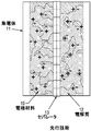
FIG. 1 is a schematic diagram of a current supercapacitor having a porous electrode. A
E = CV 2/2 = εAV 2 / 2d
(Where
E = energy density C: capacitance V: operating voltage ε: dielectric constant of separator A: effective surface area of electrode d: thickness of electric double layer).
スーパーキャパシタのエネルギー密度は、ある程度、その電極の有効表面積によって決まるので、活性炭を始めとする表面積の大きい材料が電極に採用されてきた。更に、酸化物の或るものは、物理的な表面吸着及び化学的なバルク吸収(bulk absorption)によって電荷を貯蔵するという擬似容量特性を示すことが明らかになった。それ故、擬似容量酸化物(pseudo−capacitive oxide)は、スーパーキャパシタ用に積極的に探求されている。残念なことに、これらの酸化物は低い電気伝導性を示すので、活性炭等の導電性成分によって支持しなければならない。 Since the energy density of the supercapacitor is determined to some extent by the effective surface area of the electrode, materials having a large surface area such as activated carbon have been adopted for the electrode. Furthermore, some of the oxides have been shown to exhibit pseudocapacitive properties of storing charge through physical surface adsorption and chemical bulk absorption. Therefore, pseudo-capacitive oxides are being actively explored for supercapacitors. Unfortunately, these oxides exhibit low electrical conductivity and must be supported by a conductive component such as activated carbon.
図2は、先行技術の高エネルギー密度低電力密度燃料電池、鉛蓄電池、NiCd蓄電池、ミッドレンジ・リチウム蓄電池、二重層キャパシタ、最上位・高電力密度、低エネルギー密度スーパーキャパシタ及びアルミニウム電解キャパシタを示す、米国国防兵站局(U.S.Defense Logistics Agency)から入手した、説明を要しないグラフを示すものである。図2は、それらの関係を、電力密度(w/kg)及びエネルギー密度(Wh/kg)の点から、示すものである。
FIG. 2 shows a prior art high energy density low power density fuel cell, lead acid battery, NiCd battery, mid-range lithium battery, double layer capacitor, top / high power density, low energy density supercapacitor and aluminum
14として示すスーパーキャパシタは、非常に高い電力密度(W/kg)及び中等度のエネルギー密度(Wh/kg)を有するというユニークな位置にある。 The supercapacitor shown as 14 is in a unique position with very high power density (W / kg) and moderate energy density (Wh / kg).
金属酸化物及び炭素含有材料を含有するスーパーキャパシタ電極は、1997年に特許文献6(Cottevielleら)によって教示されたように、金属塩、水性塩基及びアルコールの相互作用に基づく沈降金属水酸化物ゲルに、活性炭を添加することにより製造することができる。その全体を、バインダーを添加した電極ペーストに混ぜ込む。その後、Manthiramらは、特許文献7において、ヨウ化リチウムによって過マンガン酸ナトリウムを還元することにより製造したオキシヨウ化マンガンを、炭素等の導電性材料と混合することにより、蓄電池及びスーパーキャパシタ用途に利用した。 A supercapacitor electrode containing a metal oxide and a carbon-containing material is a precipitated metal hydroxide gel based on the interaction of a metal salt, an aqueous base and an alcohol, as taught by US Pat. Further, it can be produced by adding activated carbon. The whole is mixed in an electrode paste to which a binder is added. Thereafter, Manthiram et al., In Patent Document 7, use manganese oxyiodide produced by reducing sodium permanganate with lithium iodide for use in storage batteries and supercapacitors by mixing with a conductive material such as carbon. did.
1セットの特許、特許文献8及び特許文献9(両方ともLeeら)、は、炭素又は活性炭に過マンガン酸カリウムを吸着させ、酢酸マンガン溶液と混合して非晶質酸化マンガンを形成し、それを粉末に粉砕し、バインダーと混合して、スーパーキャパシタに好適な高キャパシタンスを有する電極を生じさせることを示した。特許文献10(Leeら)は、導電性材料を含有する集電体と、該集電体上の、導電性ポリマーで被覆した金属酸化物の活性材料とを、有する金属酸化物擬似容量キャパシタを教示している。 A set of patents, US Pat. Nos. 6,099,086 and 5,099,9 (both Lee et al.) Adsorb potassium permanganate on carbon or activated carbon and mix with manganese acetate solution to form amorphous manganese oxide, Was ground into a powder and mixed with a binder to produce an electrode with high capacitance suitable for a supercapacitor. Patent Document 10 (Lee et al.) Discloses a metal oxide pseudo-capacitance capacitor having a current collector containing a conductive material and a metal oxide active material coated with a conductive polymer on the current collector. Teaching.
必要とされているのは、新規な構造を利用する、鉛蓄電池、NiCd蓄電池及びリチウム蓄電池と同等で、燃料電池にほぼ匹敵する良好なエネルギー密度を有し、その上、アルミニウム電解キャパシタに匹敵する電力密度、周囲温度動作、迅速な応答及び長いサイクル寿命を有する、新規な改善されたスーパーキャパシタである。 What is needed is a lead-acid battery, a NiCd battery and a lithium battery that utilize a novel structure, has a good energy density comparable to a fuel cell, and is comparable to an aluminum electrolytic capacitor A new and improved supercapacitor with power density, ambient temperature operation, quick response and long cycle life.
本発明の主目的は、上述の要求を満たすスーパーキャパシタを提供することである。 The main object of the present invention is to provide a supercapacitor that satisfies the above requirements.
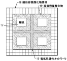
上述の要求を満たし、目的を果たすために、1)2,000m2/gより大きい表面積を有する多孔質電気伝導性グラフェン炭素ネットワークと、2)前記ネットワークによって支持された、MnO2等の、擬似容量金属酸化物の被覆とを、含有する多孔質グラフェン−酸化物ナノコンポジット電極を備えてなり、前記ネットワーク及び被覆が、図3に概略図で示すような、多孔質ナノコンポジット電極を形成する電気化学的貯蔵デバイスが提供される。図3は、擬似容量酸化物16と細孔17とを備える電気伝導性ネットワーク15を示すものである。図4では、これらの要素を、それぞれ、15’、16’及び17’として示す。図4に概略図で示すように、グラフェン炭素導電性ネットワーク15’を擬似容量酸化物骨格18の細孔に組み込むことができる。グラフェン炭素導電性ネットワーク15’の表面を、同一の又は異なる擬似容量酸化物16’で、被覆することができる。形成された複合体は、物理的にも化学的にもエネルギーを貯蔵することができる。 In order to meet the above requirements and to fulfill the objectives, 1) a porous electrically conductive graphene carbon network with a surface area greater than 2,000 m 2 / g, and 2) a pseudo, such as MnO 2 supported by said network A porous graphene-oxide nanocomposite electrode containing a capacitive metal oxide coating, wherein the network and coating form a porous nanocomposite electrode as schematically shown in FIG. A chemical storage device is provided. FIG. 3 shows an electrically conductive network 15 comprising pseudocapacitive oxide 16 and pores 17. In FIG. 4, these elements are shown as 15 ′, 16 ′ and 17 ′, respectively. As shown schematically in FIG. 4, graphene carbon conductive network 15 ′ can be incorporated into the pores of pseudocapacitive oxide skeleton 18. The surface of the graphene carbon conductive network 15 ′ can be coated with the same or different pseudocapacitance oxide 16 ′. The formed complex can store energy both physically and chemically.
グラフェンは、後述の図6に示すような、ハニカム結晶格子に稠密に充填された炭素20の平坦なシート19であって、一般に、炭素原子1個の厚さを有する。グラフェンは、2,000m2/gより大きい、好ましくは約2,000m2/gから約3,000m2/g、通常は2,500m2/gから2,000m2/gの、極めて大きな表面積を有し、電気を銀よりも良く伝導する。MnO2は、エネルギー貯蔵に対する付加的バルク関与(MnO2+K+(カリウムイオン)+e-=MnOOK)のため、高いキャパシタンスを有する。グラフィンは、活性炭、非晶質炭素及びカーボンナノチューブで代用することができ、MnO2は、NiO、RuO2、SrO2、SrRuO3で代用することができる。
Graphene is a
本発明において、新規設計ナノコンポジット電極は、表面積の大きなグラフェン炭素及び/又は被覆で酸化物を直接支持することにより、漸増量の擬似容量酸化物の利用を可能にし、これにより、該グラフェン炭素が擬似容量骨格の細孔内に収容され又は該細孔に組み込まれる(該細孔を「装飾する」)。グラフェン炭素を同一の又は異なる擬似容量酸化物で被覆することにより、その表面積が更に増加される。本明細書中において、用語「ナノコンポジット電極」は、少なくとも、個々の構成要素の1つが100ナノメートル(nm)未満の粒径を有することを意味する。電極の多孔率は、30容量%から65容量%を細孔が占めるものである。好ましくは、2つのナノコンポジット電極がセパレータのいずれかの側に配置され、各電極は、外部集電体と接触している。本明細書において、用語「装飾される」及び「装飾する」とは、被覆される/その中に収容される又はその中に組み込まれることを意味する。 In the present invention, the newly designed nanocomposite electrode allows the use of increasing amounts of pseudocapacitive oxide by directly supporting the oxide with a large surface area graphene carbon and / or coating, which It is contained within (or “decorates”) the pores of the pseudo-capacity skeleton. By coating graphene carbon with the same or different pseudocapacitive oxide, its surface area is further increased. As used herein, the term “nanocomposite electrode” means that at least one of the individual components has a particle size of less than 100 nanometers (nm). The porosity of the electrode is such that the pores occupy 30% to 65% by volume. Preferably, two nanocomposite electrodes are disposed on either side of the separator, and each electrode is in contact with an external current collector. As used herein, the terms “decorated” and “decorating” mean being coated / contained in or incorporated therein.
本発明をより良く理解するために、添付の図面に示す、本発明の例示的な好ましい実施形態を参照する:
本発明は、エネルギー密度を増すためのスーパーキャパシタにおいて電極として使用される、設計されたナノコンポジットについて記述する。図3に概略図で示すように、その限られた電気伝導性により実際の利用が妨げられる擬似容量酸化物16を、電気伝導性ネットワーク15によって支持する。細孔を17として示す。一方、図4に示すように、電気伝導性ネットワーク15’としての炭素で擬似容量骨格18の細孔を「装飾する」ことにより、ナノコンポジットを製造することができる。その表面積は、同一の又は異なる擬似容量酸化物16’で前記炭素導電性ネットワークを被覆することにより、更に増加させることができる。有用な擬似容量酸化物、即ち、図3中の16及び図4中の16’は、NiO、RuO2、SrO2、SrRuO3、MnO2及びこれらの混合物から成る群から、最も好ましくは、NiO及びMnO2から、選択される。有用な炭素は、活性炭、非晶質炭素、カーボンナノチューブ及びグラフェンから成る群から、最も好ましくは活性炭及びグラフェンから、選択される。細孔を17’として示す。形成されたナノコンポジットでは、炭素ネットワークが電子を伝導するし、一方で、擬似容量酸化物が物理的表面吸着と化学的バルク吸収との両方により、電荷貯蔵に貢献する。その結果、このナノコンポジットから作られた電極を有するスーパーキャパシタは、説明を要しない図5に、21 HED SC(高エネルギー密度スーパーキャパシタ)として示すように、高エネルギー密度を示す。 The present invention describes a designed nanocomposite used as an electrode in a supercapacitor to increase energy density. As shown schematically in FIG. 3, a pseudocapacitance oxide 16 that is impeded from practical use due to its limited electrical conductivity is supported by an electrically conductive network 15. The pore is shown as 17. On the other hand, as shown in FIG. 4, a nanocomposite can be produced by “decorating” the pores of the pseudocapacitive skeleton 18 with carbon as the electrically conductive network 15 ′. Its surface area can be further increased by coating the carbon conductive network with the same or different pseudocapacitance oxides 16 '. Useful pseudocapacitive oxides, ie 16 in FIG. 3 and 16 ′ in FIG. 4, are most preferably NiO, from the group consisting of NiO, RuO 2 , SrO 2 , SrRuO 3 , MnO 2 and mixtures thereof. And MnO 2 . Useful carbon is selected from the group consisting of activated carbon, amorphous carbon, carbon nanotubes and graphene, most preferably activated carbon and graphene. The pore is shown as 17 '. In the formed nanocomposite, the carbon network conducts electrons, while the pseudocapacitive oxide contributes to charge storage by both physical surface adsorption and chemical bulk absorption. As a result, supercapacitors having electrodes made from this nanocomposite exhibit high energy density, as shown as 21 HED SC (High Energy Density Supercapacitor) in FIG.
図6は、1原子の厚さのグラフィンの理想化平面状シート 50を示すが、そこでは、2,630m2/gの表面積を有するハニカム結晶格子に炭素原子C 51が稠密充填されている。従って、擬似容量酸化物を支持する膨大な量の表面をグラフェン炭素が供給する。 FIG. 6 shows an idealized planar sheet 50 of 1 atom thick graphene, in which a honeycomb crystal lattice having a surface area of 2,630 m 2 / g is densely packed with carbon atoms C 51. Therefore, graphene carbon supplies a huge amount of surface that supports the pseudocapacitive oxide.
図7A及び7Bは、スーパーキャパシタモードで用いられるグラフィン/酸化マンガンナノコンポジット(「GMON」)の算出エネルギー密度及び電力密度を図示するものである。1)作動電圧が0.8Vであり;2)MnO2キャパシタンスは、約698F/gであり;3)MnO2は、エネルギー貯蔵に完全に寄与し;4)迅速な動態があり;そして、5)充電/放電が60秒で起きる、と仮定している。これは、一般に、GMONナノコンポジットスーパーキャパシタのエネルギー密度が、高い電力密度エッジを維持しながら、リチウム蓄電池に匹敵するであろうことを示す。 7A and 7B illustrate the calculated energy density and power density of a graphene / manganese oxide nanocomposite (“GMON”) used in the supercapacitor mode. 1) Operating voltage is 0.8V; 2) MnO 2 capacitance is about 698 F / g; 3) MnO 2 contributes completely to energy storage; 4) Has rapid kinetics; ) Assume that charging / discharging occurs in 60 seconds. This generally indicates that the energy density of a GMON nanocomposite supercapacitor will be comparable to a lithium battery while maintaining a high power density edge.
図8は、1キログラムのナノコンポジット中のグラフェン及びMnO2の量を示すものであり、ケースI及びIIについて、それぞれ、10nm及び70nmのMnO2がグラフェン表面に被覆されている。ケースIでは、グラフェン含量70は、ナノコンポジット1kg中、71として示す992.5 MnO2に対して7.5gであり、ケースIIでは、グラフェン含量は、998.9 MnO2に対して僅か1.1であり、これはグラフェン骨格の最少量を示すものであり、図2及び図3の図から分かるものより遥かに低い。図9は、電解質に浸漬されているナノコンポジット電極23を両側に有する中央セパレータ22の概念的単一セル設計を示すものであり、この概念的単一セル設計は、アルミニウム等の正及び負の外側金属ホイル24及び25を全体に伴い、以下の仕様を有する:
・電圧:0.8V
・推定容積:18.5cm×18.5cm×0.21cm
・電極サイズ 18cm×18cm
・電極の厚み 1mm
・単一セルの総厚 2.1mm(プレート、セパレータ及び集電体)
・充電/放電時間:60秒
・電力:0.725W
・エネルギー容量:12Wh
・重量:〜174g
FIG. 8 shows the amount of graphene and MnO 2 in 1 kilogram of nanocomposite. For cases I and II, 10 nm and 70 nm of MnO 2 are coated on the graphene surface, respectively. In case I, the graphene content 70 is 7.5 g for 992.5 MnO 2 shown as 71 in 1 kg of nanocomposite, and in case II, the graphene content is only 1. for 998.9 MnO 2 . 1, which represents the minimum amount of graphene skeleton, which is much lower than what can be seen from the diagrams of FIGS. FIG. 9 shows a conceptual single cell design of a
・ Voltage: 0.8V
-Estimated volume: 18.5 cm x 18.5 cm x 0.21 cm
・ Electrode size 18cm × 18cm
・ Electrode thickness 1mm
・ Total thickness of single cell 2.1mm (plate, separator and current collector)
・ Charging / discharging time: 60 seconds ・ Power: 0.725W
・ Energy capacity: 12Wh
・ Weight: ~ 174g
本発明の特定の実施形態を詳細に説明したが、これらの詳細に対する様々な変更及び代案を本開示の全教示に鑑みて展開できることは、当業者には理解されるであろう。従って、開示した個々の実施形態は、単に例示的であることを意図したものであり、本発明の範囲について制限する意図を持たず、本発明の範囲は、添付の特許請求の範囲の全範囲及びその任意の全ての均等物により与えられるものとする。 Although particular embodiments of the present invention have been described in detail, those skilled in the art will appreciate that various modifications and alternatives to these details can be developed in light of the full teachings of the disclosure. Accordingly, each disclosed embodiment is intended to be merely exemplary and is not intended as a limitation on the scope of the invention, which is covered by the full scope of the appended claims. And any and all equivalents thereof.
Claims (10)
2)前記炭素ネットワーク(15)によって支持された、NiO、RuO2、SrO2、SrRuO3及びMnO2から成る群から選択される、擬似容量金属酸化物(16)とを、含有する多孔質ナノコンポジット電極を備えてなる電気化学エネルギー貯蔵デバイスであって、
前記ネットワーク及び酸化物が多孔質ナノコンポジット電極を形成する貯蔵デバイス。 1) a porous electrically conductive carbon network (15) having a surface area greater than 2,000 m 2 / g; and 2) NiO, RuO 2 , SrO 2 , SrRuO 3 and MnO 2 supported by said carbon network (15). An electrochemical energy storage device comprising a porous nanocomposite electrode containing a pseudocapacitive metal oxide (16) selected from the group consisting of:
A storage device wherein the network and oxide form a porous nanocomposite electrode.
Applications Claiming Priority (5)
| Application Number | Priority Date | Filing Date | Title |
|---|---|---|---|
| US23283109P | 2009-08-11 | 2009-08-11 | |
| US61/232,831 | 2009-08-11 | ||
| US12/695,405 US20110038100A1 (en) | 2009-08-11 | 2010-01-28 | Porous Carbon Oxide Nanocomposite Electrodes for High Energy Density Supercapacitors |
| US12/695,405 | 2010-01-28 | ||
| PCT/US2010/036104 WO2011019431A1 (en) | 2009-08-11 | 2010-05-26 | Porous carbon oxide nanocomposite electrodes for high energy density supercapacitors |
Publications (1)
| Publication Number | Publication Date |
|---|---|
| JP2013502070A true JP2013502070A (en) | 2013-01-17 |
Family
ID=42537635
Family Applications (1)
| Application Number | Title | Priority Date | Filing Date |
|---|---|---|---|
| JP2012524710A Pending JP2013502070A (en) | 2009-08-11 | 2010-05-26 | Porous carbon oxide nanocomposite electrodes for high energy density supercapacitors |
Country Status (11)
| Country | Link |
|---|---|
| US (1) | US20110038100A1 (en) |
| EP (1) | EP2465124A1 (en) |
| JP (1) | JP2013502070A (en) |
| KR (1) | KR20120043092A (en) |
| CN (1) | CN102473532A (en) |
| BR (1) | BR112012003129A2 (en) |
| CA (1) | CA2770624A1 (en) |
| IN (1) | IN2012DN00552A (en) |
| MX (1) | MX2012001775A (en) |
| RU (1) | RU2012108855A (en) |
| WO (1) | WO2011019431A1 (en) |
Cited By (8)
| Publication number | Priority date | Publication date | Assignee | Title |
|---|---|---|---|---|
| JP2013151398A (en) * | 2012-01-26 | 2013-08-08 | Dowa Electronics Materials Co Ltd | Method for reducing graphene oxide, and method for producing electrode material using the method |
| JP2015502033A (en) * | 2011-11-10 | 2015-01-19 | ザ リージェンツ オブ ザ ユニバーシティ オブ コロラド,ア ボディー コーポレイトTHE REGENTS OF THE UNIVERSITY OF COLORADO,a body corporate | Supercapacitor device having a composite electrode formed by depositing a metal oxide pseudocapacitor material on a carbon substrate |
| KR101561961B1 (en) * | 2014-03-19 | 2015-10-20 | 고려대학교 산학협력단 | All solid state planar type supercapacitor and fabrication method thereof |
| KR101561959B1 (en) * | 2014-03-17 | 2015-10-20 | 고려대학교 산학협력단 | All solid state flexible micro-supercapacitor with patterned graphene and fabrication method thereof |
| JP2016166113A (en) * | 2015-03-10 | 2016-09-15 | 株式会社仁科マテリアル | Carbon-metal complex |
| JP2018538773A (en) * | 2015-11-26 | 2018-12-27 | ザップゴー リミテッド | Portable electronic devices |
| JP2019505990A (en) * | 2016-01-11 | 2019-02-28 | ナノテク インストゥルメンツ, インコーポレイテッドNanotek Instruments, Inc. | Supercapacitor with highly conductive graphene foam electrode |
| KR20240023503A (en) | 2021-06-25 | 2024-02-22 | 가부시기가이샤에프.씨.씨 | Capacitor electrode and manufacturing method of capacitor electrode |
Families Citing this family (23)
| Publication number | Priority date | Publication date | Assignee | Title |
|---|---|---|---|---|
| WO2012144993A1 (en) * | 2011-04-20 | 2012-10-26 | Empire Technology Development, Llc | Chemical vapor deposition graphene foam electrodes for pseudo-capacitors |
| CN104125925A (en) | 2011-12-21 | 2014-10-29 | 加州大学评议会 | Interconnected corrugated carbon-based network |
| JP6325462B2 (en) | 2012-03-05 | 2018-05-16 | ザ リージェンツ オブ ザ ユニバーシティ オブ カリフォルニア | Capacitors with electrodes made of interconnected corrugated carbon-based networks |
| CN102671655B (en) * | 2012-06-08 | 2014-08-06 | 浙江大学 | Manganese oxide/ graphene catalyst for preparing amide by alcohol ammonia oxidation |
| CN103730257A (en) * | 2012-10-16 | 2014-04-16 | 海洋王照明科技股份有限公司 | Manganese dioxide/graphene composite electrode material, preparing method thereof, and electrochemical capacitor |
| US10692660B2 (en) | 2013-11-08 | 2020-06-23 | The Regents Of The University Of California | Three-dimensional graphene framework-based high-performance supercapacitors |
| EA201790003A1 (en) | 2014-06-16 | 2019-07-31 | Дзе Риджентс Ов Зе Юниверсити Ов Калифорния | HYBRID ELECTRICAL CELL |
| JP2018501644A (en) | 2014-11-18 | 2018-01-18 | ザ リージェンツ オブ ザ ユニバーシティ オブ カリフォルニア | Porous interconnected corrugated carbon based network (ICCN) composites |
| US9905370B2 (en) * | 2015-03-05 | 2018-02-27 | Tuqiang Chen | Energy storage electrodes and devices |
| CN108025178B (en) * | 2015-09-16 | 2021-09-28 | 心脏起搏器股份公司 | Assembly technique for sintered anodes and sintered cathodes |
| CN108431918B (en) | 2015-12-22 | 2020-12-29 | 加利福尼亚大学董事会 | Honeycomb graphene film |
| WO2017127539A1 (en) | 2016-01-22 | 2017-07-27 | The Regents Of The University Of California | High-voltage devices |
| AU2017238201B2 (en) | 2016-03-23 | 2022-01-27 | Nanotech Energy, Inc. | Devices and methods for high voltage and solar applications |
| CN109074967B (en) | 2016-04-01 | 2022-07-08 | 加利福尼亚大学董事会 | Method for directly growing polyaniline nanotubes on carbon cloth for flexible high-performance super capacitor |
| US11097951B2 (en) | 2016-06-24 | 2021-08-24 | The Regents Of The University Of California | Production of carbon-based oxide and reduced carbon-based oxide on a large scale |
| MX2019001891A (en) | 2016-08-31 | 2019-07-08 | Univ California | Devices comprising carbon-based material and fabrication thereof. |
| CN106531449B (en) * | 2016-10-24 | 2018-04-06 | 上海应用技术大学 | A kind of preparation method of nanometer sheet core shell structure |
| CN106531460B (en) * | 2016-11-28 | 2018-03-20 | 上海应用技术大学 | A kind of mesoporous nickel oxide/manganese oxide/carbon nano-composite material, preparation method and applications |
| WO2019005143A1 (en) * | 2017-06-30 | 2019-01-03 | Intel Corporation | Super lattice capacitor |
| EP3652797B1 (en) | 2017-07-14 | 2023-11-22 | The Regents of The University of California | Simple route to highly conductive porous graphene from carbon nanodots for supercapacitor applications |
| US10014124B1 (en) * | 2017-09-27 | 2018-07-03 | King Saud University | Composite electrode material for supercapacitors |
| US11038179B2 (en) * | 2019-04-03 | 2021-06-15 | Tuqiang Chen | Flexible energy storage devices |
| US10938032B1 (en) | 2019-09-27 | 2021-03-02 | The Regents Of The University Of California | Composite graphene energy storage methods, devices, and systems |
Citations (2)
| Publication number | Priority date | Publication date | Assignee | Title |
|---|---|---|---|---|
| JP2004503456A (en) * | 2000-05-24 | 2004-02-05 | ファインセル カンパニー リミテッド | Medium porous carbon material, carbon / metal oxide composite material, and electrochemical capacitor using the material |
| WO2005121022A1 (en) * | 2004-06-11 | 2005-12-22 | Tokyo University Of Agriculture And Technology, National University Corporation | Nanocarbon composite structure having ruthenium oxide trapped therein |
Family Cites Families (15)
| Publication number | Priority date | Publication date | Assignee | Title |
|---|---|---|---|---|
| US3977901A (en) * | 1974-10-23 | 1976-08-31 | Westinghouse Electric Corporation | Metal/air cells and improved air electrodes for use therein |
| US4078125A (en) * | 1976-05-27 | 1978-03-07 | Westinghouse Electric Corporation | Energy density iron-silver battery |
| US4054729A (en) * | 1976-10-27 | 1977-10-18 | Westinghouse Electric Corporation | Rechargeable high temperature electrochemical battery |
| FR2720542B1 (en) * | 1994-05-30 | 1996-07-05 | Alsthom Cge Alcatel | Method of manufacturing a supercapacitor electrode. |
| US6331282B1 (en) * | 1997-11-10 | 2001-12-18 | Board Of Regents, The University Of Texas System | Manganese oxyiodides and their method of preparation and use in energy storage |
| JP2001217000A (en) * | 1999-02-26 | 2001-08-10 | Toshiba Battery Co Ltd | Nickel-hydrogen secondary battery |
| US6339528B1 (en) * | 1999-09-16 | 2002-01-15 | Ness Capacitor Co., Ltd. | Metal oxide electrode for supercapacitor and manufacturing method thereof |
| KR100414357B1 (en) * | 2001-07-13 | 2004-01-07 | 주식회사 네스캡 | Conducting Polymer Coated Electrode of Metal Oxide Electrochemical Pseudocapacitor and Method of Manufacturing the Same |
| US20030108785A1 (en) * | 2001-12-10 | 2003-06-12 | Wu L. W. | Meso-porous carbon and hybrid electrodes and method for producing the same |
| EP1643583A4 (en) * | 2003-07-29 | 2010-01-20 | Panasonic Corp | Lithium ion secondary battery |
| US7724500B2 (en) * | 2006-09-11 | 2010-05-25 | The United States Of America As Represented By The Secretary Of The Navy | Nanoscale manganese oxide on ultraporous carbon nanoarchitecture |
| KR100894481B1 (en) * | 2007-04-16 | 2009-04-22 | 한국과학기술연구원 | Electrode for supercapacitor having metal oxide deposited onto ultrafine carbon fiber and the fabrication method thereof |
| US7948739B2 (en) * | 2007-08-27 | 2011-05-24 | Nanotek Instruments, Inc. | Graphite-carbon composite electrode for supercapacitors |
| US7986509B2 (en) * | 2008-01-17 | 2011-07-26 | Fraser Wade Seymour | Composite electrode comprising a carbon structure coated with a thin film of mixed metal oxides for electrochemical energy storage |
| KR101614449B1 (en) * | 2009-01-22 | 2016-04-21 | 삼성전자주식회사 | Transition metal/carbon-nano-tube composites and method of manufacturing the same |
-
2010
- 2010-01-28 US US12/695,405 patent/US20110038100A1/en not_active Abandoned
- 2010-05-26 JP JP2012524710A patent/JP2013502070A/en active Pending
- 2010-05-26 WO PCT/US2010/036104 patent/WO2011019431A1/en active Application Filing
- 2010-05-26 CN CN2010800355846A patent/CN102473532A/en active Pending
- 2010-05-26 CA CA2770624A patent/CA2770624A1/en not_active Abandoned
- 2010-05-26 RU RU2012108855/07A patent/RU2012108855A/en not_active Application Discontinuation
- 2010-05-26 EP EP10726733A patent/EP2465124A1/en not_active Withdrawn
- 2010-05-26 BR BR112012003129A patent/BR112012003129A2/en not_active IP Right Cessation
- 2010-05-26 MX MX2012001775A patent/MX2012001775A/en not_active Application Discontinuation
- 2010-05-26 KR KR1020127006362A patent/KR20120043092A/en not_active Application Discontinuation
- 2010-05-26 IN IN552DEN2012 patent/IN2012DN00552A/en unknown
Patent Citations (2)
| Publication number | Priority date | Publication date | Assignee | Title |
|---|---|---|---|---|
| JP2004503456A (en) * | 2000-05-24 | 2004-02-05 | ファインセル カンパニー リミテッド | Medium porous carbon material, carbon / metal oxide composite material, and electrochemical capacitor using the material |
| WO2005121022A1 (en) * | 2004-06-11 | 2005-12-22 | Tokyo University Of Agriculture And Technology, National University Corporation | Nanocarbon composite structure having ruthenium oxide trapped therein |
Cited By (9)
| Publication number | Priority date | Publication date | Assignee | Title |
|---|---|---|---|---|
| JP2015502033A (en) * | 2011-11-10 | 2015-01-19 | ザ リージェンツ オブ ザ ユニバーシティ オブ コロラド,ア ボディー コーポレイトTHE REGENTS OF THE UNIVERSITY OF COLORADO,a body corporate | Supercapacitor device having a composite electrode formed by depositing a metal oxide pseudocapacitor material on a carbon substrate |
| JP2013151398A (en) * | 2012-01-26 | 2013-08-08 | Dowa Electronics Materials Co Ltd | Method for reducing graphene oxide, and method for producing electrode material using the method |
| KR101561959B1 (en) * | 2014-03-17 | 2015-10-20 | 고려대학교 산학협력단 | All solid state flexible micro-supercapacitor with patterned graphene and fabrication method thereof |
| KR101561961B1 (en) * | 2014-03-19 | 2015-10-20 | 고려대학교 산학협력단 | All solid state planar type supercapacitor and fabrication method thereof |
| JP2016166113A (en) * | 2015-03-10 | 2016-09-15 | 株式会社仁科マテリアル | Carbon-metal complex |
| JP2018538773A (en) * | 2015-11-26 | 2018-12-27 | ザップゴー リミテッド | Portable electronic devices |
| JP2019505990A (en) * | 2016-01-11 | 2019-02-28 | ナノテク インストゥルメンツ, インコーポレイテッドNanotek Instruments, Inc. | Supercapacitor with highly conductive graphene foam electrode |
| JP7149850B2 (en) | 2016-01-11 | 2022-10-07 | ナノテク インストゥルメンツ,インコーポレイテッド | Supercapacitors with highly conductive graphene foam electrodes |
| KR20240023503A (en) | 2021-06-25 | 2024-02-22 | 가부시기가이샤에프.씨.씨 | Capacitor electrode and manufacturing method of capacitor electrode |
Also Published As
| Publication number | Publication date |
|---|---|
| EP2465124A1 (en) | 2012-06-20 |
| CA2770624A1 (en) | 2011-02-17 |
| WO2011019431A1 (en) | 2011-02-17 |
| BR112012003129A2 (en) | 2016-03-01 |
| US20110038100A1 (en) | 2011-02-17 |
| MX2012001775A (en) | 2012-06-12 |
| KR20120043092A (en) | 2012-05-03 |
| RU2012108855A (en) | 2013-10-20 |
| IN2012DN00552A (en) | 2015-06-12 |
| CN102473532A (en) | 2012-05-23 |
Similar Documents
| Publication | Publication Date | Title |
|---|---|---|
| JP2013502070A (en) | Porous carbon oxide nanocomposite electrodes for high energy density supercapacitors | |
| Shukla et al. | Electrochemical capacitors: Technical challenges and prognosis for future markets | |
| Halper et al. | Supercapacitors: A brief overview | |
| Zheng | Theoretical energy density for electrochemical capacitors with intercalation electrodes | |
| JP2020123571A (en) | Hybrid electric electrochemical cell | |
| JP6622802B2 (en) | Silicon secondary battery | |
| US9385539B2 (en) | Surface-mediated cell-powered portable computing devices and methods of operating same | |
| JP2002118036A (en) | Electricity storage electronic component and composite electrode body | |
| Zheng | Energy density theory of lithium-ion capacitors | |
| Yin et al. | Asymmetric supercapacitors based on the in situ-grown mesoporous nickel oxide and activated carbon | |
| JP2010062299A (en) | Electricity storage device | |
| Béguin | Application of nanotextured carbons for electrochemical energy storage in aqueous medium | |
| KR102028677B1 (en) | Multilayer lithium-ion capacitor comprising graphene electrode | |
| JPWO2011161832A1 (en) | Current collector material for electrode and manufacturing method thereof | |
| KR101368226B1 (en) | Electrode structure comprising the electrode materialand secondary battery comprising the electrodestructure | |
| KR101205846B1 (en) | Lithium ion capacitor having current collector of plate type | |
| JP5035993B2 (en) | Electric double layer capacitor | |
| Klobukoski et al. | Device configuration—asymmetric versus hybrid supercapacitors | |
| JP2006128049A (en) | Electronic component for storage of electricity | |
| KR101383250B1 (en) | Electrode structure comprising the electrode materialand secondary battery comprising the electrodestructure | |
| Rajasekaran et al. | A Survey on Supercapacitor Based Batteries | |
| Drobnyi | The effect of nanoporous electrode composition on supercapacitor performance | |
| KR101468732B1 (en) | Electrode structure comprising the electrode materialand secondary battery comprising the electrodestructure | |
| KR101396792B1 (en) | Electrode structure comprising the electrode materialand secondary battery comprising the electrodestructure | |
| JP2005223155A (en) | Electrochemical device and electrode member |
Legal Events
| Date | Code | Title | Description |
|---|---|---|---|
| A977 | Report on retrieval |
Free format text: JAPANESE INTERMEDIATE CODE: A971007 Effective date: 20130725 |
|
| A131 | Notification of reasons for refusal |
Free format text: JAPANESE INTERMEDIATE CODE: A131 Effective date: 20130827 |
|
| A02 | Decision of refusal |
Free format text: JAPANESE INTERMEDIATE CODE: A02 Effective date: 20140401 |