JP2013249897A - Multiple valve device - Google Patents

Multiple valve device Download PDF

Info

Publication number
JP2013249897A
JP2013249897A JP2012125125A JP2012125125A JP2013249897A JP 2013249897 A JP2013249897 A JP 2013249897A JP 2012125125 A JP2012125125 A JP 2012125125A JP 2012125125 A JP2012125125 A JP 2012125125A JP 2013249897 A JP2013249897 A JP 2013249897A
Authority
JP
Japan
Prior art keywords
housing block
hydraulic
oil passage
passage
pressure
Prior art date
Legal status (The legal status is an assumption and is not a legal conclusion. Google has not performed a legal analysis and makes no representation as to the accuracy of the status listed.)
Pending
Application number
JP2012125125A
Other languages
Japanese (ja)
Other versions
JP2013249897A5 (en
Inventor
Satoru Kubota
哲 窪田
Mitsuhisa Togasaki
光久 東ヶ崎
Yoshinobu Kobayashi
義伸 小林
Hiroshi Matsuzaki
浩 松崎
Current Assignee (The listed assignees may be inaccurate. Google has not performed a legal analysis and makes no representation or warranty as to the accuracy of the list.)
Hitachi Construction Machinery Co Ltd
Original Assignee
Hitachi Construction Machinery Co Ltd
Priority date (The priority date is an assumption and is not a legal conclusion. Google has not performed a legal analysis and makes no representation as to the accuracy of the date listed.)
Filing date
Publication date
Application filed by Hitachi Construction Machinery Co Ltd filed Critical Hitachi Construction Machinery Co Ltd
Priority to JP2012125125A priority Critical patent/JP2013249897A/en
Priority to KR20147025688A priority patent/KR20150018767A/en
Priority to PCT/JP2013/064206 priority patent/WO2013179969A1/en
Publication of JP2013249897A publication Critical patent/JP2013249897A/en
Publication of JP2013249897A5 publication Critical patent/JP2013249897A5/ja
Pending legal-status Critical Current

Links

Images

Classifications

    • FMECHANICAL ENGINEERING; LIGHTING; HEATING; WEAPONS; BLASTING
    • F15FLUID-PRESSURE ACTUATORS; HYDRAULICS OR PNEUMATICS IN GENERAL
    • F15BSYSTEMS ACTING BY MEANS OF FLUIDS IN GENERAL; FLUID-PRESSURE ACTUATORS, e.g. SERVOMOTORS; DETAILS OF FLUID-PRESSURE SYSTEMS, NOT OTHERWISE PROVIDED FOR
    • F15B13/00Details of servomotor systems ; Valves for servomotor systems
    • F15B13/02Fluid distribution or supply devices characterised by their adaptation to the control of servomotors
    • F15B13/06Fluid distribution or supply devices characterised by their adaptation to the control of servomotors for use with two or more servomotors
    • F15B13/08Assemblies of units, each for the control of a single servomotor only
    • F15B13/0803Modular units
    • F15B13/0832Modular valves
    • F15B13/0842Monoblock type valves, e.g. with multiple valve spools in a common housing
    • FMECHANICAL ENGINEERING; LIGHTING; HEATING; WEAPONS; BLASTING
    • F15FLUID-PRESSURE ACTUATORS; HYDRAULICS OR PNEUMATICS IN GENERAL
    • F15BSYSTEMS ACTING BY MEANS OF FLUIDS IN GENERAL; FLUID-PRESSURE ACTUATORS, e.g. SERVOMOTORS; DETAILS OF FLUID-PRESSURE SYSTEMS, NOT OTHERWISE PROVIDED FOR
    • F15B13/00Details of servomotor systems ; Valves for servomotor systems
    • F15B13/02Fluid distribution or supply devices characterised by their adaptation to the control of servomotors
    • F15B13/06Fluid distribution or supply devices characterised by their adaptation to the control of servomotors for use with two or more servomotors
    • F15B13/08Assemblies of units, each for the control of a single servomotor only
    • F15B13/0803Modular units
    • F15B13/0871Channels for fluid
    • FMECHANICAL ENGINEERING; LIGHTING; HEATING; WEAPONS; BLASTING
    • F16ENGINEERING ELEMENTS AND UNITS; GENERAL MEASURES FOR PRODUCING AND MAINTAINING EFFECTIVE FUNCTIONING OF MACHINES OR INSTALLATIONS; THERMAL INSULATION IN GENERAL
    • F16KVALVES; TAPS; COCKS; ACTUATING-FLOATS; DEVICES FOR VENTING OR AERATING
    • F16K27/00Construction of housing; Use of materials therefor
    • F16K27/003Housing formed from a plurality of the same valve elements
    • FMECHANICAL ENGINEERING; LIGHTING; HEATING; WEAPONS; BLASTING
    • F15FLUID-PRESSURE ACTUATORS; HYDRAULICS OR PNEUMATICS IN GENERAL
    • F15BSYSTEMS ACTING BY MEANS OF FLUIDS IN GENERAL; FLUID-PRESSURE ACTUATORS, e.g. SERVOMOTORS; DETAILS OF FLUID-PRESSURE SYSTEMS, NOT OTHERWISE PROVIDED FOR
    • F15B2211/00Circuits for servomotor systems
    • F15B2211/20Fluid pressure source, e.g. accumulator or variable axial piston pump
    • F15B2211/205Systems with pumps
    • F15B2211/20576Systems with pumps with multiple pumps
    • FMECHANICAL ENGINEERING; LIGHTING; HEATING; WEAPONS; BLASTING
    • F15FLUID-PRESSURE ACTUATORS; HYDRAULICS OR PNEUMATICS IN GENERAL
    • F15BSYSTEMS ACTING BY MEANS OF FLUIDS IN GENERAL; FLUID-PRESSURE ACTUATORS, e.g. SERVOMOTORS; DETAILS OF FLUID-PRESSURE SYSTEMS, NOT OTHERWISE PROVIDED FOR
    • F15B2211/00Circuits for servomotor systems
    • F15B2211/70Output members, e.g. hydraulic motors or cylinders or control therefor
    • F15B2211/71Multiple output members, e.g. multiple hydraulic motors or cylinders
    • F15B2211/7142Multiple output members, e.g. multiple hydraulic motors or cylinders the output members being arranged in multiple groups

Abstract

PROBLEM TO BE SOLVED: To suppress oil leak or the like by reducing the number of connection ports in joining surfaces to a requisite minimum when pressure oil is supplied to a multiple valve device by two hydraulic pumps.SOLUTION: A valve housing 12 of a multiple valve device 11 is divided into two blocks in the vertical direction, a first housing block 13 and a second housing block 14. A total of four connection ports 67C, 69C, 73C, 74C are disposed at locations of joining surfaces 13B, 14A between the first housing block 13 and the second housing block 14. In supplying pressure oil to all control valves 26, 30, 34, 38, 47, 48, 54, 55, and 61 from a first and a second hydraulic pumps 77, 79, the number of the connection ports 67C, 69C, 73C, and 74C is reduced to a requisite minimum to suppress an oil leak or the like in between the joining surfaces 13B, 14A.

Description

本発明は、例えば油圧ショベル等の建設機械に搭載され、走行用および作業用油圧アクチュエータを駆動制御するのに好適に用いられる多連弁装置に関する。   The present invention relates to a multiple valve device that is mounted on a construction machine such as a hydraulic excavator and is suitably used for driving and controlling a traveling hydraulic actuator and a working hydraulic actuator.

一般に、油圧ショベル等の建設機械では、例えば油圧ポンプ等の油圧源から油圧アクチュエータ(例えば、油圧モータ、油圧シリンダ等)に圧油を給排するため、該油圧アクチュエータと油圧源との間に複数のスプール弁(方向制御弁)からなる多連弁装置を設ける構成としている。   In general, in a construction machine such as a hydraulic excavator, pressure oil is supplied to and discharged from a hydraulic actuator (for example, a hydraulic motor, a hydraulic cylinder, etc.) from a hydraulic source such as a hydraulic pump. A multi-valve device comprising a spool valve (direction control valve) is provided.

この種の従来技術による多連弁装置は、複数個のスプール摺動穴を有し該各スプール摺動穴に連通する油圧源側油通路,アクチュエータ側油通路がそれぞれ設けられた弁ハウジングと、該弁ハウジングの各スプール摺動穴内にそれぞれ挿嵌して設けられ前記油圧源側油通路とアクチュエータ側油通路とを選択的に連通,遮断する複数個のスプールとを備えている。   This type of prior art multiple valve device has a plurality of spool sliding holes, a valve housing provided with a hydraulic source side oil passage and an actuator side oil passage respectively communicating with the spool sliding holes, A plurality of spools are provided which are inserted into the respective spool sliding holes of the valve housing and selectively connect and disconnect the hydraulic source side oil passage and the actuator side oil passage.

また、このような多連弁装置に用いる弁ハウジングとしては、例えば3個以上のハウジングブロックを互いの合せ面で衝合して重ね合せる構成としたスタック型と、2分割して形成された2つのハウジングブロックを合せ面の位置で互いに衝合させる構成とした2分割型と、全体を単一のハウジングブロックとして形成したモノブロック型との3タイプが知られている(例えば、特許文献1,2,3,4参照)。   Moreover, as a valve housing used for such a multiple valve device, for example, a stack type in which three or more housing blocks are abutted and overlapped with each other on a mating surface, and a two-divided 2 is formed. Three types are known: a two-part type in which two housing blocks are brought into contact with each other at the position of the mating surface, and a mono-block type in which the whole is formed as a single housing block (for example, Patent Document 1, 2, 3, 4).

実開昭50−55921号公報Japanese Utility Model Publication No. 50-55921 特開昭59−186502号公報JP 59-186502 A 特開平4−73404号公報JP-A-4-73404 特開2000−205426号公報JP 2000-205426 A

ところで、上述した従来技術では、例えばスタック型の弁ハウジングの場合、3個以上のハウジングブロックを互いの合せ面で衝合して重ね合せる構成であるため、各ハウジングブロックの合せ面を高精度に仕上げ加工する必要があり、ブロック毎の仕上げ加工等に手間がかかって製造、組立て時の作業性が悪いという問題がある。また、モノブロック型の弁ハウジングは、単一の大きなブロック体であるために、重量物となって移送、搬送時の取扱い性、作業性が悪くなるという問題がある。   By the way, in the above-described prior art, for example, in the case of a stack type valve housing, since three or more housing blocks are abutted and overlapped with each other on the mating surfaces, the mating surfaces of the respective housing blocks are highly accurate. There is a problem that it is necessary to finish the work, and it takes time to finish the work for each block, resulting in poor workability during manufacture and assembly. In addition, since the monoblock type valve housing is a single large block body, there is a problem that it becomes a heavy object and the handling property and workability at the time of transfer and transportation deteriorate.

一方、従来技術による2分割型の弁ハウジングは、モノブロック型に比較して1ブロックとしては約半分の重量とすることができ、鋳型の一部である中子の構造も簡略化することができる。また、スタック型に比較しても合せ面の個数を減らすことができ、シール不良等の発生も低減できるという利点がある。しかし、この場合には、内蔵するスプールの個数を増やすために各ハウジングブロックの寸法を大きく形成する必要がある。ハウジングブロックの寸法を大きくし、合せ面の面積を広くしたときには、当該合せ面における油通路の接続ポートに高圧の作動油が流れるときに、合せ面の位置でシール不良、油漏れ等が発生する可能性がある。   On the other hand, the two-part valve housing according to the prior art can be about half the weight of one block as compared with the monoblock type, and the structure of the core that is a part of the mold can be simplified. it can. In addition, the number of mating surfaces can be reduced compared to the stack type, and there is an advantage that occurrence of defective seals can be reduced. However, in this case, it is necessary to increase the size of each housing block in order to increase the number of built-in spools. When the size of the housing block is increased and the area of the mating surface is increased, when high-pressure hydraulic fluid flows through the connection port of the oil passage on the mating surface, poor sealing or oil leakage occurs at the mating surface position. there is a possibility.

特に、油圧源として2つの油圧ポンプを用いる場合、例えば油圧ショベルのブームシリンダとアームシリンダとには、2つの油圧ポンプからの圧油を合流させて供給することがある。しかし、このような合流箇所が増えると、前記合せ面における油通路の接続ポート数が増えることになり、これによって、合せ面における油漏れの可能性が高くなるという問題がある。   In particular, when two hydraulic pumps are used as the hydraulic source, for example, the hydraulic oil from the two hydraulic pumps may be supplied to the boom cylinder and the arm cylinder of the excavator. However, when the number of such joining points is increased, the number of connection ports of the oil passage on the mating surface is increased, which increases the possibility of oil leakage on the mating surface.

本発明は上述した従来技術の問題に鑑みなされたもので、本発明の目的は、2分割型の弁ハウジングの利点を活かしつつ、2つの油圧ポンプ間で圧油を供給する場合にも合せ面における油通路の接続ポート数を必要最小限に減らし、油漏れ等の発生を抑えることができるようにした多連弁装置を提供することにある。   The present invention has been made in view of the above-described problems of the prior art, and the object of the present invention is to provide a mating surface even when pressure oil is supplied between two hydraulic pumps while taking advantage of the two-part valve housing. It is an object of the present invention to provide a multi-valve device that can reduce the number of connection ports of an oil passage to the minimum necessary and suppress the occurrence of oil leakage and the like.

上述した課題を解決するために、本発明は、複数の油圧源側油通路と複数のアクチュエータ側油通路とに連通するスプール摺動穴が6個以上設けられた弁ハウジングと、該弁ハウジングの各スプール摺動穴内にそれぞれ挿嵌して設けられ前記油圧源側油通路と前記アクチュエータ側油通路とを連通,遮断する6個以上のスプールとを備え、第1,第2の油圧ポンプを含んだ2つの油圧源による圧油の流れを、前記複数のスプールを用いて制御する構成としてなる多連弁装置に適用される。   In order to solve the above-described problem, the present invention provides a valve housing provided with six or more spool sliding holes communicating with a plurality of hydraulic source side oil passages and a plurality of actuator side oil passages, And six or more spools that are inserted into the respective spool sliding holes and communicate with and shut off the hydraulic source side oil passage and the actuator side oil passage, and include first and second hydraulic pumps. However, the present invention is applied to a multiple valve device configured to control the flow of pressure oil by two hydraulic sources using the plurality of spools.

そして、請求項1の発明が採用する構成の特徴は、前記弁ハウジングは、対向する合せ面の位置で互いに衝合,離間される3個以上の前記スプールを備えた一側ハウジングブロックと、残り3個以上の前記スプールを備えた他側ハウジングブロックとに2分割する構成とし、前記第1の油圧ポンプは、前記一側,他側ハウジングブロックのうちいずれか一方のハウジングブロックに設けられた前記油圧源側油通路に接続して設け、前記第1の油圧ポンプからの圧油は、前記一方のハウジングブロックのうち前記合せ面に近い位置に配置された前記スプールよりも上流側となる位置から前記合せ面を通じて他方のハウジングブロックに備えた前記複数のスプールの一部に供給される構成とし、前記第2の油圧ポンプは、前記一側,他側ハウジングブロックのうち他方のハウジングブロックに設けられた前記油圧源側油通路に接続して設け、前記第2の油圧ポンプからの圧油は、前記他方のハウジングブロックのうち前記合せ面に近い位置に配置された前記スプールよりも上流側となる位置から前記合せ面を通じて前記一方のハウジングブロックに備えた前記複数のスプールの一部に供給される構成としたことにある。   A feature of the configuration adopted by the invention of claim 1 is that the valve housing has a one-side housing block having three or more spools which are abutted and separated from each other at the position of the facing mating surfaces, and the rest. The first hydraulic pump is configured to be divided into two or more other housing blocks including three or more spools, and the first hydraulic pump is provided in any one of the one side and other side housing blocks. Connected to a hydraulic pressure source side oil passage, the pressure oil from the first hydraulic pump is from a position upstream of the spool disposed near the mating surface in the one housing block. The second hydraulic pump is configured to be supplied to a part of the plurality of spools provided in the other housing block through the mating surface. Provided in connection with the oil pressure source side oil passage provided in the other housing block of the blocks, and the pressure oil from the second hydraulic pump is disposed at a position close to the mating surface in the other housing block. According to another aspect of the present invention, a part of the plurality of spools provided in the one housing block is supplied through the mating surface from a position upstream of the spool.

請求項2の発明が採用する構成の特徴は、前記弁ハウジングは、対向する合せ面の位置で互いに衝合,離間される3個以上の前記スプールを備えた一側ハウジングブロックと、残り3個以上の前記スプールを備えた他側ハウジングブロックとに2分割する構成とし、前記第1の油圧ポンプは、前記一側,他側ハウジングブロックのうちいずれか一方のハウジングブロックに設けられた前記油圧源側油通路に接続して設け、前記第1の油圧ポンプからの圧油は、前記一方のハウジングブロックのうち前記合せ面に近い位置に配置された前記スプールよりも上流側となる位置から前記合せ面を通じて他方のハウジングブロックに備えた前記複数のスプールの一部に供給される構成とし、前記第2の油圧ポンプは、前記一方のハウジングブロックに設けられた前記複数の油圧源側油通路のうち前記第1の油圧ポンプが接続された前記油圧源側油通路とは異なる油圧源側油通路に接続して設け、前記第2の油圧ポンプからの圧油は、前記一方のハウジングブロックのうち前記合せ面に近い位置に配置された前記スプールよりも上流側となる位置から前記合せ面を通じて前記他方のハウジングブロックに備えた前記複数のスプールの一部とは別のスプールに供給される構成としたことにある。   The feature of the configuration adopted by the invention of claim 2 is that the valve housing has one side housing block having three or more spools which are abutted and separated from each other at the position of the facing mating surfaces, and the remaining three The first hydraulic pump is configured to be divided into two, that is, the other housing block having the spool described above, and the first hydraulic pump is provided with one of the one side and the other side housing blocks. Pressure oil from the first hydraulic pump is provided in connection with a side oil passage, and the mating is performed from a position upstream of the spool disposed at a position near the mating surface in the one housing block. The second hydraulic pump is connected to the one housing block through a surface and supplied to a part of the plurality of spools provided in the other housing block. A plurality of hydraulic source side oil passages connected to a hydraulic source side oil passage that is different from the hydraulic source side oil passage to which the first hydraulic pump is connected; and from the second hydraulic pump The pressure oil of one of the plurality of spools provided in the other housing block through the mating surface from a position upstream of the spool disposed at a position close to the mating surface in the one housing block. The configuration is such that the spool is supplied to a spool different from the part.

請求項3の発明によると、前記一方のハウジングブロックは、前記複数の油圧源側油通路を前記第1の油圧ポンプに接続される第1の一側油通路系統と前記第2の油圧ポンプに接続される第2の一側油通路系統とに分離して形成し、前記他方のハウジングブロックは、前記複数の油圧源側油通路を前記第1の油圧ポンプに接続される第1の他側油通路系統と前記第2の油圧ポンプに接続される第2の他側油通路系統とに分離して形成し、前記一方のハウジングブロックに形成された前記第1の一側油通路系統は、前記他方のハウジングブロックに形成された前記第1の他側油通路系統に前記合せ面を通じて連通する構成とし、前記一方のハウジングブロックに形成された前記第2の一側油通路系統は、前記他方のハウジングブロックに形成された前記第2の他側油通路系統に前記合せ面を通じて連通する構成としている。   According to a third aspect of the present invention, the one housing block is connected to the first one-side oil passage system and the second hydraulic pump, wherein the plurality of hydraulic source-side oil passages are connected to the first hydraulic pump. The second housing block is formed separately from the second one-side oil passage system to be connected, and the other housing block has the plurality of hydraulic source-side oil passages connected to the first hydraulic pump. An oil passage system and a second other-side oil passage system connected to the second hydraulic pump are separately formed, and the first one-side oil passage system formed in the one housing block includes: The second other oil passage system formed in the one housing block is configured to communicate with the first other oil passage system formed in the other housing block through the mating surface. Formed on the housing block It is configured to communicate through the mating surface to said second other-side oil passage lineages.

請求項4の発明が採用する構成の特徴は、前記弁ハウジングは、対向する合せ面の位置で互いに衝合,離間される3個以上の前記スプールを備えた一側ハウジングブロックと、残り3個以上の前記スプールを備えた他側ハウジングブロックとに2分割する構成とし、前記一側ハウジングブロックは、前記複数の油圧源側油通路を前記第1の油圧ポンプに接続される第1の一側油通路系統と前記第2の油圧ポンプに接続される第2の一側油通路系統とに分離して形成し、前記他側ハウジングブロックは、前記複数の油圧源側油通路を前記第1の油圧ポンプに接続される第1の他側油通路系統と前記第2の油圧ポンプに接続される第2の他側油通路系統とに分離して形成し、前記一側ハウジングブロックに形成された前記第1の一側油通路系統は、前記他側ハウジングブロックに形成された前記第1の他側油通路系統に前記合せ面を通じて連通する構成とし、前記一側ハウジングブロックに形成された前記第2の一側油通路系統は、前記他側ハウジングブロックに形成された前記第2の他側油通路系統に前記合せ面を通じて連通する構成としたことにある。   The feature of the configuration adopted by the invention of claim 4 is that the valve housing has one side housing block having three or more spools which are abutted and separated from each other at the position of the facing mating surfaces, and the remaining three The first housing block is divided into two parts, the other housing block having the spool, and the one housing block is connected to the first hydraulic pump through the plurality of hydraulic source side oil passages. An oil passage system and a second one-side oil passage system connected to the second hydraulic pump are separately formed, and the other housing block includes the plurality of hydraulic source side oil passages in the first A first other-side oil passage system connected to the hydraulic pump and a second other-side oil passage system connected to the second hydraulic pump are separately formed and formed in the one-side housing block The first one-side oil passage system is The second one-side oil passage system formed in the one-side housing block is configured to communicate with the first other-side oil passage system formed in the other-side housing block through the mating surface. The present invention is configured to communicate with the second other oil passage system formed in the side housing block through the mating surface.

請求項5の発明によると、前記第1の一側油通路系統は、前記第1の油圧ポンプからの圧油を前記一側ハウジングブロックのうち前記合せ面に近い位置に配置された前記スプールよりも上流側となる位置から前記合せ面を通じて前記他側ハウジングブロックの前記第1の他側油通路系統に供給する構成とし、前記第2の他側油通路系統は、前記第2の油圧ポンプからの圧油を前記他側ハウジングブロックのうち前記合せ面に近い位置に配置された前記スプールよりも上流側となる位置から前記合せ面を通じて前記一側ハウジングブロックの前記第2の一側油通路系統に供給する構成としている。   According to a fifth aspect of the present invention, the first one-side oil passage system receives pressure oil from the first hydraulic pump from the spool disposed at a position close to the mating surface in the one-side housing block. The second other oil passage system is supplied from the second hydraulic pump through the mating surface to the first other oil passage system of the other housing block. The second one-side oil passage system of the one-side housing block through the mating surface from a position upstream of the spool disposed at a position close to the mating surface in the other-side housing block. It is configured to supply to.

請求項6の発明によると、前記第1の一側油通路系統は、前記第1の油圧ポンプからの圧油を前記一側ハウジングブロックのうち前記合せ面に近い位置に配置された前記スプールよりも上流側となる位置から前記合せ面を通じて前記他側ハウジングブロックの前記第1の他側油通路系統に供給する構成とし、前記第2の一側油通路系統は、前記第2の油圧ポンプからの圧油を前記一側ハウジングブロックのうち前記合せ面に近い位置に配置された前記スプールよりも上流側となる位置から前記合せ面を通じて前記他側ハウジングブロックの前記第2の他側油通路系統に供給する構成としている。   According to a sixth aspect of the present invention, the first one-side oil passage system receives pressure oil from the first hydraulic pump from the spool disposed at a position close to the mating surface in the one-side housing block. Is configured to supply the first other-side oil passage system of the other-side housing block from the upstream position through the mating surface, and the second one-side oil passage system is connected to the second hydraulic pump. The second other-side oil passage system of the other-side housing block through the mating surface from a position upstream of the spool disposed in the position near the mating surface in the one-side housing block. It is configured to supply to.

請求項7の発明によると、前記一側,他側ハウジングブロックのうちいずれか一方のハウジングブロックには、当該ハウジングブロックの4隅となる部位をそれぞれ切欠くことにより形成され前記合せ面との間がボルト締結用の座面部となる4個の凹窪部を設け、該4個の凹窪部の座面部は、複数のボルトを用いて前記一側ハウジングブロックと他側ハウジングブロックとを衝合状態で固着するための4個の締結部を構成し、前記複数の油圧源側油通路のうち前記第1の油圧ポンプまたは前記第2の油圧ポンプに接続され前記合せ面の位置を通る高圧側の油通路は、前記合せ面の中央側寄りの位置に配置する構成としている。   According to the invention of claim 7, any one of the one side housing block and the other side housing block is formed by cutting out the four corners of the housing block, and is formed between the mating surfaces. Are provided with four recessed portions that become seat surfaces for fastening bolts, and the seat surface portions of the four recessed portions engage the one side housing block and the other side housing block using a plurality of bolts. High-pressure side passing through the position of the mating surface connected to the first hydraulic pump or the second hydraulic pump among the plurality of hydraulic source-side oil passages The oil passage is arranged at a position closer to the center side of the mating surface.

請求項8の発明によると、前記複数のスプールのうち供給された圧油が互いに合流する関係にある2つのスプールは、前記一側,他側ハウジングブロックのうち一方側の同じハウジングブロック内に設ける構成としている。   According to an eighth aspect of the present invention, two spools of the plurality of spools in which the supplied pressure oils merge with each other are provided in the same housing block on one side of the one side and other side housing blocks. It is configured.

請求項9の発明によると、前記弁ハウジングは、前記各スプール摺動穴内にそれぞれ挿嵌して設けられた前記各スプールと共に建設機械に用いる複数の方向制御弁を構成し、前記複数のスプールのうち供給された圧油が互いに合流する関係にある2つのスプールは、前記建設機械のブームシリンダを制御するために設けられた第1のブーム用スプールと第2のブーム用スプール、または、アームシリンダを制御するために設けられた第1のアーム用スプールと第2のアーム用スプールとにより構成している。   According to a ninth aspect of the present invention, the valve housing constitutes a plurality of directional control valves used for a construction machine together with the spools that are respectively inserted and fitted into the spool sliding holes, Two spools in which the supplied pressure oils merge with each other are a first boom spool and a second boom spool provided for controlling the boom cylinder of the construction machine, or an arm cylinder. The first arm spool and the second arm spool are provided to control the movement.

上述の如く、請求項1に記載の発明によれば、一側,他側ハウジングブロックのいずれか一方のハウジングブロック内に設けられた複数のスプールのうち予め決められたスプールには、第1の油圧ポンプからの圧油を油圧源側油通路を介して供給できると共に、他方のハウジングブロック内に設けられた複数のスプールの一部にも、前記第1の油圧ポンプからの圧油を合せ面を通じて供給することができ、このためには一つの接続ポートを前記合せ面の位置に設けるだけでよくなる。また、他方のハウジングブロック内に設けられた複数のスプールのうち予め決められたスプールには、第2の油圧ポンプからの圧油を油圧源側油通路を介して供給できると共に、一方のハウジングブロック内に設けられた複数のスプールの一部にも、前記第2の油圧ポンプからの圧油を合せ面を通じて供給することができ、このためには前記合せ面の位置に他の接続ポートを一つ設けるだけでよくなる。この結果、2分割型の弁ハウジングの利点を活かしつつ、2つの油圧ポンプ間で圧油を供給する場合にも合せ面における油通路の接続ポート数を必要最小限に減らすことができ、油漏れ等の発生を抑えることができる。   As described above, according to the first aspect of the present invention, the predetermined spool among the plurality of spools provided in one of the one side housing block and the other side housing block includes the first spool. The pressure oil from the hydraulic pump can be supplied through the oil pressure source side oil passage, and the pressure oil from the first hydraulic pump is also joined to a part of the plurality of spools provided in the other housing block. For this purpose, it is only necessary to provide one connection port at the position of the mating surface. In addition, pressure oil from the second hydraulic pump can be supplied to a predetermined spool among the plurality of spools provided in the other housing block through the hydraulic power source side oil passage, and one housing block Pressure oil from the second hydraulic pump can also be supplied through a mating surface to some of the plurality of spools provided therein, and for this purpose, another connection port is provided at the position of the mating surface. Just install one. As a result, the number of connection ports of the oil passage on the mating surface can be reduced to the minimum necessary even when pressure oil is supplied between the two hydraulic pumps while utilizing the advantages of the two-part valve housing. Etc. can be suppressed.

また、多連弁装置の弁ハウジングを2分割して形成された一側,他側ハウジングブロック(即ち、一方と他方のハウジングブロック)により構成でき、これら2つのハウジングブロックを、相手方と対向する合せ面の位置で互いに衝合したり、離間したりすることができる。前記一側ハウジングブロック内には、3個以上のスプール摺動穴を前記合せ面に対し平行な方向と垂直な方向とに立体構造をなす配置関係をもって配設することができ、前記他側ハウジングブロック内でも、残り3〜6のスプール摺動穴を前記合せ面に対し平行な方向と垂直な方向とに他の立体構造をなす配置関係をもって配設することができる。このため、スプール摺動穴(スプール弁)の個数を増やすときには、合せ面に垂直な方向でハウジングブロックの寸法を大きくして対応でき、合せ面に平行な方向での寸法を大きくする必要がなく、合せ面の面積を可能な限り小さくすることができる。   Further, the valve housing of the multiple valve device can be constituted by one side and other side housing blocks formed by dividing the valve housing into two parts (that is, one and the other housing block), and these two housing blocks are aligned to face each other. They can abut or separate from each other at the surface position. Within the one-side housing block, three or more spool sliding holes can be arranged with a three-dimensional structure in a direction parallel to and perpendicular to the mating surface. Even in the block, the remaining three to six spool sliding holes can be arranged with another three-dimensional structure in a direction parallel to and perpendicular to the mating surface. For this reason, when increasing the number of spool sliding holes (spool valves), the housing block can be sized in the direction perpendicular to the mating surface, and there is no need to increase the dimension in the direction parallel to the mating surface. The area of the mating surface can be made as small as possible.

請求項2の発明では、一側,他側ハウジングブロックのいずれか一方のハウジングブロック内に設けられた複数のスプールのうち予め決められたスプールには、第1の油圧ポンプからの圧油を油圧源側油通路を介して供給できると共に、他方のハウジングブロック内に設けられた複数のスプールの一部にも、第1の油圧ポンプからの圧油を合せ面を通じて供給することができ、このためには一つの接続ポートを前記合せ面の位置に設けるだけでよい。また、一方のハウジングブロック内に設けられた前記スプールとは別のスプールには、一方のハウジングブロックに設けられた複数の油圧源側油通路のうち前記第1の油圧ポンプが接続された油圧源側油通路とは異なる油圧源側油通路により、第2の油圧ポンプからの圧油を供給できると共に、他方のハウジングブロック内に設けられた複数のスプールの一部とは別のスプールにも、第2の油圧ポンプからの圧油を合せ面を通じて供給することができ、このためには前記合せ面の位置に他の接続ポートを一つ設けるだけでよい。この結果、2分割型の弁ハウジングの利点を活かしつつ、2つの油圧ポンプ間で圧油を供給する場合にも合せ面における油通路の接続ポート数を必要最小限に減らすことができ、油漏れ等の発生を抑えることができる。   According to the second aspect of the present invention, pressure oil from the first hydraulic pump is hydraulically applied to a predetermined spool among a plurality of spools provided in either one of the one side housing block and the other side housing block. The pressure oil from the first hydraulic pump can be supplied through the mating surface to a part of the plurality of spools provided in the other housing block, and can be supplied through the source side oil passage. It is only necessary to provide one connection port at the position of the mating surface. Also, a hydraulic pressure source to which the first hydraulic pump is connected among a plurality of hydraulic source side oil passages provided in one housing block is connected to a spool different from the spool provided in one housing block. Pressure oil from the second hydraulic pump can be supplied by a hydraulic source side oil passage different from the side oil passage, and also in a spool different from some of the plurality of spools provided in the other housing block, The pressure oil from the second hydraulic pump can be supplied through the mating surface. To this end, it is only necessary to provide one other connection port at the position of the mating surface. As a result, the number of connection ports of the oil passage on the mating surface can be reduced to the minimum necessary even when pressure oil is supplied between the two hydraulic pumps while utilizing the advantages of the two-part valve housing. Etc. can be suppressed.

請求項3の発明によれば、一方のハウジングブロックに形成された第1の一側油通路系統を、他方のハウジングブロックに形成された第1の他側油通路系統に合せ面を通じて連通することができ、前記一方のハウジングブロックに形成された第2の一側油通路系統を、他方のハウジングブロックに形成された第2の他側油通路系統に前記合せ面を通じて連通することができる。   According to the invention of claim 3, the first one-side oil passage system formed in one housing block communicates with the first other-side oil passage system formed in the other housing block through a mating surface. The second one-side oil passage system formed in the one housing block can be communicated with the second other-side oil passage system formed in the other housing block through the mating surface.

また、請求項4〜6の発明でも、前述した請求項1〜3の発明とほぼ同様な効果を得ることができる。請求項5の発明では、第1の油圧ポンプからの圧油を第1の一側油通路系統を介して一側ハウジングブロック内のスプールに供給できると共に、第1の油圧ポンプからの圧油を合せ面を通じて他側ハウジングブロックの第1の他側油通路系統に供給することができる。第2の油圧ポンプからの圧油は、第2の他側油通路系統を介して他側ハウジングブロック内のスプールに供給できると共に、一側ハウジングブロックの第2の一側油通路系統にも前記合せ面を通じて供給することができる。一方、請求項6の発明では、第2の油圧ポンプからの圧油を一側ハウジングブロック内のスプールに第2の一側油通路系統を介して供給できると共に、第2の油圧ポンプからの圧油を合せ面を通じて他側ハウジングブロックの第2の他側油通路系統に供給することができる。   The inventions of claims 4 to 6 can provide substantially the same effects as those of the inventions of claims 1 to 3 described above. In the invention of claim 5, the pressure oil from the first hydraulic pump can be supplied to the spool in the one-side housing block via the first one-side oil passage system, and the pressure oil from the first hydraulic pump can be supplied. The first other oil passage system of the other housing block can be supplied through the mating surface. The pressure oil from the second hydraulic pump can be supplied to the spool in the other side housing block via the second other side oil passage system, and also to the second one side oil passage system of the one side housing block. Can be supplied through mating surfaces. On the other hand, in the invention of claim 6, the pressure oil from the second hydraulic pump can be supplied to the spool in the one side housing block via the second one side oil passage system, and the pressure from the second hydraulic pump can be supplied. Oil can be supplied to the second other oil passage system of the other housing block through the mating surface.

請求項7の発明によると、一側ハウジングブロックと他側ハウジングブロックとを合せ面の位置で衝合した状態で複数のボルトを用いて締結することができ、前記合せ面の位置を通る高圧側の油通路を前記合せ面の中央側寄りの位置に配置することができる。これにより、合せ面の位置を通る高圧側の油通路を低圧側の油通路よりも前記合せ面の中央側寄りの位置に設けることができ、これらの油通路を流通する圧油が合せ面の位置から外部に漏洩するのを抑えることができる。   According to the seventh aspect of the present invention, the one side housing block and the other side housing block can be fastened by using a plurality of bolts in a state where the one side housing block and the other side housing block are brought into contact with each other at the mating surface position. The oil passage can be disposed at a position closer to the center side of the mating surface. Accordingly, the oil passage on the high pressure side passing through the position of the mating surface can be provided at a position closer to the center side of the mating surface than the oil passage on the low pressure side, and the pressure oil flowing through these oil passages Leakage from the position to the outside can be suppressed.

請求項8の発明では、第1,第2の油圧ポンプから吐出される圧油を同一のハウジングブロック内で合流して2つのスプールに供給することができ、このための合流通路を2つのハウジングブロックの合せ面の位置に設ける必要がない。これによって、前記合せ面における接続ポートの数を減らすことができ、油漏れ等の発生を抑えることができる。   According to the eighth aspect of the present invention, the pressure oil discharged from the first and second hydraulic pumps can be merged in the same housing block and supplied to the two spools. It is not necessary to provide at the position of the mating surface of the block. As a result, the number of connection ports on the mating surfaces can be reduced, and the occurrence of oil leakage or the like can be suppressed.

請求項9の発明によると、例えば油圧ショベル等の建設機械に多連弁装置を搭載することにより、走行用の油圧アクチュエータおよび作業用の油圧アクチュエータをそれぞれ個別に駆動制御する複数の方向制御弁として多連弁装置を用いることができる。このうちブームシリンダを制御するために設けられた第1のブーム用スプールと第2のブーム用スプールは、同じハウジングブロック内に設けることにより、第1,第2の油圧ポンプから吐出される圧油を一つのハウジングブロック内で合流して2つのスプールに供給することができる。また、アームシリンダを制御するために設けられた第1のアーム用スプールと第2のアーム用スプールについても、同じハウジングブロック内に設けることにより、第1,第2の油圧ポンプから吐出される圧油を一つのハウジングブロック内で合流して2つのスプールに供給することができる。   According to the ninth aspect of the present invention, as a plurality of directional control valves that individually drive and control the traveling hydraulic actuator and the working hydraulic actuator by mounting a multiple valve device on a construction machine such as a hydraulic excavator, for example. Multiple valve devices can be used. Among these, the first boom spool and the second boom spool provided for controlling the boom cylinder are provided in the same housing block, so that the pressure oil discharged from the first and second hydraulic pumps is provided. Can be combined in one housing block and supplied to two spools. Also, the first arm spool and the second arm spool provided for controlling the arm cylinder are also provided in the same housing block, so that the pressures discharged from the first and second hydraulic pumps. Oil can be merged in one housing block and fed to two spools.

本発明の第1の実施の形態による多連弁装置が搭載された油圧ショベルを示す全体図である。1 is an overall view showing a hydraulic excavator equipped with a multiple valve device according to a first embodiment of the present invention. 図1中の多連弁装置を拡大して示す斜視図である。It is a perspective view which expands and shows the multiple valve apparatus in FIG. 多連弁装置を図2とは反対側からみた斜視図である。It is the perspective view which looked at the multiple valve apparatus from the opposite side to FIG. 多連弁装置を図2中の矢示IV−IV方向からみた縦断面図である。It is the longitudinal cross-sectional view which looked at the multiple valve apparatus from the arrow IV-IV direction in FIG. 多連弁装置を図2中の矢示V−V方向からみた縦断面図である。It is the longitudinal cross-sectional view which looked at the multiple valve apparatus from the arrow VV direction in FIG. 多連弁装置を図2中の矢示VI−VI方向からみた縦断面図である。It is the longitudinal cross-sectional view which looked at the multiple valve apparatus from the arrow VI-VI direction in FIG. 一側ハウジングブロックを左,右の走行用制御弁等と共に図5中の矢示VII−VII方向からみた横断面図である。FIG. 7 is a cross-sectional view of the one-side housing block as viewed from the direction of arrows VII-VII in FIG. 5 together with the left and right traveling control valves and the like. 一側ハウジングブロックをバケット用制御弁および予備の制御弁等と共に図5中の矢示VIII−VIII方向からみた横断面図である。It is the cross-sectional view which looked at the 1 side housing block from the arrow VIII-VIII direction in FIG. 5 with the control valve for buckets, a backup control valve, etc. 一側ハウジングブロックをリリーフ弁等と共に図5中の矢示IX−IX方向からみた横断面図である。It is the cross-sectional view which looked at the 1 side housing block from the arrow IX-IX direction in FIG. 5 with the relief valve. 他側ハウジングブロックをブーム用制御弁等と共に図5中の矢示X−X方向からみた横断面図である。It is the cross-sectional view which looked at the other side housing block from the arrow XX direction in FIG. 5 with the boom control valve. 他側ハウジングブロックをアーム用制御弁等と共に図5中の矢示XI−XI方向からみた横断面図である。It is the cross-sectional view which looked at the other side housing block from the arrow XI-XI direction in FIG. 5 with the control valve for arms. 他側ハウジングブロックを旋回用制御弁等と共に図5中の矢示 XII−XII 方向からみた横断面図である。It is the cross-sectional view which looked at the other side housing block from the arrow XII-XII direction in FIG. 他側ハウジングブロックを合せ面の位置で図5中の矢示XIII−XIII方向からみた横断面図である。It is the cross-sectional view which looked at the other side housing block from the arrow XIII-XIII direction in FIG. 図1に示す油圧ショベルに用いる多連弁装置の油圧回路図である。FIG. 2 is a hydraulic circuit diagram of a multiple valve device used in the hydraulic excavator shown in FIG. 1. 比較例による多連弁装置の油圧回路図である。It is a hydraulic circuit diagram of the multiple valve apparatus by a comparative example. 第2の実施の形態による多連弁装置の油圧回路図である。It is a hydraulic-circuit figure of the multiple valve apparatus by 2nd Embodiment.

以下、本発明の実施の形態による多連弁装置を、建設機械としての油圧ショベルに搭載した場合を例に挙げ、添付図面を参照して詳細に説明する。   Hereinafter, a case where the multiple valve device according to the embodiment of the present invention is mounted on a hydraulic excavator as a construction machine will be described as an example and described in detail with reference to the accompanying drawings.

なお、実施の形態の記載では、多連弁装置の代表例として、一側ハウジングブロックに合計4個の前記スプール摺動穴を設け、他側ハウジングブロックに合計5個の前記スプール摺動穴を設ける場合を例に挙げている。しかし、本発明に係る多連弁装置は、これに限るものではなく、6〜12個のスプール摺動穴が設けられた弁ハウジングのうち、一側ハウジングブロックに3個〜6個のスプール摺動穴を設け、他側ハウジングブロックに3個〜6個のスプール摺動穴を設ける構成としてもよいものである。   In the description of the embodiment, as a representative example of the multiple valve device, a total of four spool sliding holes are provided in one housing block, and a total of five spool sliding holes are provided in the other housing block. The case of providing is given as an example. However, the multiple valve device according to the present invention is not limited to this, and among the valve housings provided with 6 to 12 spool sliding holes, 3 to 6 spool slides are provided on one housing block. A moving hole may be provided, and 3 to 6 spool sliding holes may be provided in the other housing block.

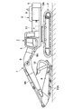
ここで、図1ないし図14は、本発明の第1の実施の形態に係る多連弁装置を示している。図において、1は建設機械としての油圧ショベルで、該油圧ショベル1は、図1に示すように自走可能なクローラ式の下部走行体2と、該下部走行体2上に旋回可能に搭載された上部旋回体3と、後述の作業装置7とにより大略構成されている。この場合、油圧ショベル1の上部旋回体3は、下部走行体2と共に建設機械の車体を構成するものである。上部旋回体3は、下部走行体2上で旋回駆動される旋回フレーム3Aを有し、この旋回フレーム3A上には、後述のキャブ4、カウンタウエイト5および建屋カバー6等が設けられている。   Here, FIG. 1 thru | or FIG. 14 has shown the multiple valve apparatus which concerns on the 1st Embodiment of this invention. In the figure, reference numeral 1 denotes a hydraulic excavator as a construction machine. The hydraulic excavator 1 is mounted on a crawler type lower traveling body 2 capable of self-propelling as shown in FIG. The upper revolving body 3 and a work device 7 to be described later are roughly configured. In this case, the upper swing body 3 of the hydraulic excavator 1 constitutes the vehicle body of the construction machine together with the lower traveling body 2. The upper turning body 3 has a turning frame 3A that is driven to turn on the lower traveling body 2, and a cab 4, a counterweight 5, a building cover 6, and the like, which will be described later, are provided on the turning frame 3A.

4は旋回フレーム3Aの前部左側に配設されたキャブで、該キャブ4は、略四角形の箱体として形成され、その内部に運転室を画成している。キャブ4の内側には、オペレータが着座する運転席の他に、作業用の操作レバー、走行用レバー(いずれも図示せず)等が設けられている。   Reference numeral 4 denotes a cab disposed on the left side of the front portion of the swivel frame 3A. The cab 4 is formed as a substantially rectangular box and defines a cab inside thereof. In addition to the driver's seat on which the operator is seated, an operation lever for operation, a travel lever (none of which are shown) and the like are provided inside the cab 4.

5は旋回フレーム3Aの後端側に設けられたカウンタウエイトで、該カウンタウエイト5は、旋回フレーム3Aの後端側に着脱可能に搭載され、前側の作業装置7に対して上部旋回体3全体の重量バランスをとるものである。また、カウンタウエイト5の前側には、エンジン(図示せず)等を収容する後述の建屋カバー6が設けられている。   Reference numeral 5 denotes a counterweight provided on the rear end side of the swing frame 3A. The counterweight 5 is detachably mounted on the rear end side of the swing frame 3A, and the entire upper swing body 3 with respect to the work device 7 on the front side. The weight balance is taken. A building cover 6 (described later) that houses an engine (not shown) or the like is provided on the front side of the counterweight 5.

6はキャブ4とカウンタウエイト5との間に位置して旋回フレーム3A上に立設された建屋カバーである。この建屋カバー6は、例えば薄い鋼板からなる複数枚の金属パネルを用いて形成され、内部にエンジン等を収容する機械室(図示せず)を画成するものである。建屋カバー6内には、前記エンジンによって回転駆動される後述の油圧ポンプ77,79(図14参照)が設けられている。また、建屋カバー6内には、キャブ4に近い位置に後述の多連弁装置11が設けられている。   A building cover 6 is located between the cab 4 and the counterweight 5 and is erected on the turning frame 3A. The building cover 6 is formed using, for example, a plurality of metal panels made of thin steel plates, and defines a machine room (not shown) that houses an engine or the like inside. In the building cover 6, hydraulic pumps 77 and 79 (see FIG. 14) described later that are driven to rotate by the engine are provided. In the building cover 6, a multiple valve device 11 described later is provided at a position close to the cab 4.

7は上部旋回体3の前部に俯仰動可能に設けられた作業装置で、該作業装置7は、基端側が旋回フレーム3Aに俯仰動可能に取付けられたブーム8と、該ブーム8の先端側に俯仰動可能に取付けられたアーム9と、例えば土砂等の掘削作業を行うため該アーム9の先端側に回動可能に設けられた作業具としてのバケット10とにより大略構成されている。   Reference numeral 7 denotes a working device provided at the front of the upper swing body 3 so as to be able to move up and down. The working device 7 includes a boom 8 whose base end is attached to the turning frame 3A so as to be able to move up and down, and a tip of the boom 8 The arm 9 is mounted on the side so as to be able to move up and down, and for example, a bucket 10 as a work tool that is rotatably provided on the distal end side of the arm 9 for excavation work such as earth and sand.

作業装置7のブーム8は、ブームシリンダ8Aにより旋回フレーム3Aに対して上,下に俯仰動され、アーム9は、ブーム8の先端側でアームシリンダ9Aにより上,下に俯仰動される。また、作業具としてのバケット10は、アーム9の先端側で作業具用シリンダとしてのバケットシリンダ10Aにより上,下に回動されるものである。   The boom 8 of the working device 7 is moved up and down with respect to the revolving frame 3A by the boom cylinder 8A, and the arm 9 is moved up and down by the arm cylinder 9A on the tip side of the boom 8. The bucket 10 as a work tool is rotated up and down by a bucket cylinder 10A as a work tool cylinder on the tip side of the arm 9.

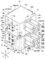
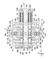
次に、11は第1の実施の形態で採用した多連弁装置で、この多連弁装置11は、図2〜図14に示すように弁ハウジング12と、後述のスプール27,31,35,39,49,51,56,58,62およびリリーフ弁88等とにより構成されている。そして、多連弁装置11の弁ハウジング12は、図2〜図6等に示すように、後述する一側ハウジングブロック13と他側ハウジングブロック14とにより2分割して形成されている。   Next, reference numeral 11 denotes a multiple valve device employed in the first embodiment. This multiple valve device 11 includes a valve housing 12 and spools 27, 31, 35, which will be described later, as shown in FIGS. , 39, 49, 51, 56, 58, 62, a relief valve 88, and the like. And the valve housing 12 of the multiple valve apparatus 11 is divided into two by a one-side housing block 13 and an other-side housing block 14 which will be described later, as shown in FIGS.

ここで、一側ハウジングブロック13と他側ハウジングブロック14は、後述の合せ面13B,14Aに対して平行な左,右方向(図2中のX軸方向)と前,後方向(Y軸方向)に延びると共に、合せ面13B,14Aに垂直な上,下方向(Z軸方向)にもそれぞれ延びる直方体状のブロックとして形成される。一側ハウジングブロック13と他側ハウジングブロック14とは、合せ面13B,14Aの位置で互いに分離可能に衝合されるものである。   Here, the one-side housing block 13 and the other-side housing block 14 are arranged in a left and right direction (X-axis direction in FIG. 2) and a front and rear direction (Y-axis direction) parallel to mating surfaces 13B and 14A described later. ) And a block having a rectangular parallelepiped shape extending in the upper and lower directions (Z-axis direction) perpendicular to the mating surfaces 13B and 14A. The one-side housing block 13 and the other-side housing block 14 are abutted so as to be separable from each other at the positions of the mating surfaces 13B and 14A.

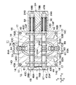
13は弁ハウジング12の半割体となる一側ハウジングブロックで、該一側ハウジングブロック13は、鋳造等の手段を用いて図2〜図7に示す如く直方体状をなす鋳造品として成形されている。一側ハウジングブロック13は、上側の一面13A(以下、上面13Aという)、下側の合せ面13B、前,後の側面13C,13Dおよび左,右の側面13E,13Fからなる合計6個の面を有している。   Reference numeral 13 denotes a one-side housing block which is a half of the valve housing 12, and the one-side housing block 13 is molded as a rectangular parallelepiped cast product as shown in FIGS. Yes. The one-side housing block 13 has a total of six surfaces including an upper surface 13A (hereinafter referred to as an upper surface 13A), a lower mating surface 13B, front and rear side surfaces 13C and 13D, and left and right side surfaces 13E and 13F. have.

図2に示すように、一側ハウジングブロック13には、前側の側面13Cのうち後述のカバー81Aよりも上側となる位置に後述のポンプポート65が開口して設けられている。また、前側の側面13Cには、左,右方向(X軸方向)に離間した位置に後述の圧油給排ポート29A,29Bと圧油給排ポート37A,37Bとがそれぞれ開口して設けられている。図3に示すように、後側の側面13Dには、左,右方向(X軸方向)に離間した位置にそれぞれ開口して、後述の圧油給排ポート33A,33Bと圧油給排ポート41A,41Bとが設けられている。   As shown in FIG. 2, the one-side housing block 13 is provided with a later-described pump port 65 opened at a position above the later-described cover 81 </ b> A on the front side surface 13 </ b> C. Further, on the front side surface 13C, pressure oil supply / discharge ports 29A, 29B and pressure oil supply / discharge ports 37A, 37B, which will be described later, are opened at positions separated from each other in the left and right directions (X-axis direction). ing. As shown in FIG. 3, the rear side surface 13D is opened at positions spaced leftward and rightward (in the X-axis direction), and pressure oil supply / discharge ports 33A and 33B and pressure oil supply / discharge ports described later are opened. 41A and 41B are provided.

14は弁ハウジング12の他の半割体を構成する他側ハウジングブロックで、該他側ハウジングブロック14も、鋳造等の手段により直方体状のブロック(鋳物)として成形されている。他側ハウジングブロック14は、上側の合せ面14A、下側の他面14B(以下、下面14Bという)、前,後の側面14C,14Dおよび左,右の側面14E,14Fからなる合計6個の面を有している。   Reference numeral 14 denotes an other housing block constituting another half of the valve housing 12, and the other housing block 14 is also formed as a rectangular parallelepiped block (casting) by means such as casting. The other housing block 14 has a total of six parts including an upper mating surface 14A, a lower other surface 14B (hereinafter referred to as a lower surface 14B), front and rear side surfaces 14C and 14D, and left and right side surfaces 14E and 14F. Has a surface.

図2に示すように、他側ハウジングブロック14には、前側の側面14Cのうち後述のカバー85Aよりも下側となる位置に後述のポンプポート71が開口して設けられ、ポンプポート71よりもX軸方向で左側となる位置には後述のタンクポート75が開口して設けられている。また、前側の側面14Cには、後述の圧油給排ポート53A,53Bが左,右方向(X軸方向)に離間して設けられている。図3に示すように、後側の側面14Dには、後述の圧油給排ポート60A,60Bと圧油給排ポート64A,64Bとがそれぞれ左,右方向(X軸方向)に離間して設けられている。   As shown in FIG. 2, the other side housing block 14 is provided with a later-described pump port 71 opened at a position lower than a later-described cover 85 </ b> A on the front side surface 14 </ b> C. A tank port 75 (described later) is provided open at a position on the left side in the X-axis direction. In addition, pressure oil supply / discharge ports 53A and 53B, which will be described later, are provided on the front side surface 14C so as to be spaced apart in the left and right directions (X-axis direction). As shown in FIG. 3, pressure oil supply / discharge ports 60A and 60B, which will be described later, and pressure oil supply / discharge ports 64A and 64B are separated from each other in the left and right directions (X-axis direction) on the rear side surface 14D. Is provided.

15は一側ハウジングブロック13に形成した複数(例えば、合計4個)の凹窪部で、これらの凹窪部15は、合せ面13Bよりも上側となる位置で一側ハウジングブロック13の4隅となる各角隅部(即ち、前,後の側面13C,13Dと左,右の側面13E,13Fとの間の角隅部)を、それぞれ断面L字状に切欠いて凹設することにより形成されている。   Reference numeral 15 denotes a plurality of (for example, a total of four) recessed portions formed in the one-side housing block 13, and these recessed portions 15 are located at the four corners of the one-side housing block 13 at positions above the mating surface 13B. Are formed by notching each of the corners (that is, the corners between the front and rear side surfaces 13C and 13D and the left and right side surfaces 13E and 13F) into a L-shaped cross section. Has been.

各凹窪部15の下面側は、合せ面13Bとの間がボルト締結用の座面部15Aとなり、これらの座面部15Aは、複数のボルト16,16,…を用いて一側ハウジングブロック13を他側ハウジングブロック14に衝合状態で固着(結合)するための締結部を構成している。そして、凹窪部15は、座面部15Aの上側位置にボルト16用のボルト装着スペースを形成するものである。   The lower surface side of each recessed portion 15 is a seat surface portion 15A for fastening bolts between the mating surface 13B, and these seat surface portions 15A are used to mount the one-side housing block 13 using a plurality of bolts 16, 16,. A fastening portion is configured to be fixed (coupled) to the other housing block 14 in an abutting state. And the recessed part 15 forms the volt | bolt mounting space for the volt | bolts 16 in the upper position of 15 A of seat surface parts.

ここで、各凹窪部15の座面部15A(締結部)は、バケット用制御弁34、予備の制御弁38を含む各スプール弁よりも合せ面13Bに近い位置に設けられ、前記スプール弁と合せ面13Bとの間となる位置に配置されている。また、各凹窪部15の座面部15Aに対して必ずしも1本のボルト16を締結する必要はなく、場合によっては、1つの座面部15Aに対して2本以上のボルト16を締結する構成としてもよい。   Here, the seat surface portion 15A (fastening portion) of each recessed portion 15 is provided at a position closer to the mating surface 13B than each spool valve including the bucket control valve 34 and the spare control valve 38, and the spool valve It arrange | positions in the position which becomes between the mating surfaces 13B. In addition, it is not always necessary to fasten one bolt 16 to the seating surface portion 15A of each recessed portion 15, and in some cases, two or more bolts 16 are fastened to one seating surface portion 15A. Also good.

他側ハウジングブロック14には、合せ面14Aのうち前記各座面部15Aと上,下で対向する位置にそれぞれねじ穴17(図10、図13参照)が形成され、これらのねじ穴17には、ボルト16がそれぞれ螺着されている。これにより、一側ハウジングブロック13と他側ハウジングブロック14とは、合計4本のボルト16を用いて衝合状態に固着され、多連弁装置11の弁ハウジング12を構成するものである。   The other side housing block 14 is formed with screw holes 17 (see FIGS. 10 and 13) at positions facing the respective seating surface portions 15A above and below the mating surface 14A. The bolts 16 are respectively screwed. As a result, the one-side housing block 13 and the other-side housing block 14 are fixed in an abutting state by using a total of four bolts 16 and constitute the valve housing 12 of the multiple valve device 11.

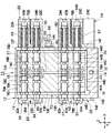
18,19,20,21は一側ハウジングブロック13に設けられた4個の前記スプール摺動穴で、該スプール摺動穴18〜21は、図2に示す後述のカバー体22と同様に立体構造をなして一側ハウジングブロック13内に配置されている。スプール摺動穴18〜21は、図4、図5、図7、図8に示す如くX軸方向に沿って互いに並行に延び、Y軸方向とZ軸方向では互いに離間する構成となっている。   18, 19, 20, 21 are four spool sliding holes provided in the one-side housing block 13, and the spool sliding holes 18 to 21 are three-dimensional like the cover body 22 described later shown in FIG. 2. A structure is arranged in the one-side housing block 13. The spool sliding holes 18 to 21 extend in parallel to each other along the X-axis direction as shown in FIGS. 4, 5, 7, and 8, and are separated from each other in the Y-axis direction and the Z-axis direction. .

ここで、一側ハウジングブロック13に設けるスプール摺動穴の個数は4個に限らず、スプール摺動穴を立体構造をなすように最少個数として3個設ける構成としてもよい。この場合、一側ハウジングブロック13には、例えば後述の走行用制御弁26,30、バケット用制御弁34の合計3個のスプール摺動穴18,19,20を設け、予備の制御弁38用のスプール摺動穴21は省略する構成としてもよい。   Here, the number of spool sliding holes provided in the one-side housing block 13 is not limited to four, and a configuration may be adopted in which three spool sliding holes are provided as a minimum so as to form a three-dimensional structure. In this case, the one-side housing block 13 is provided with a total of three spool sliding holes 18, 19, and 20, for example, travel control valves 26 and 30 and a bucket control valve 34, which will be described later, for the spare control valve 38. The spool sliding hole 21 may be omitted.

スプール摺動穴18〜21のうちスプール摺動穴18,19は、図7に示すようにX軸方向では並行して延び、Y軸方向には所定の間隔をもって配置されている。また、スプール摺動穴20,21も、図8に示すようにX軸方向で並行して延び、Y軸方向には所定の間隔をもって配置されている。スプール摺動穴18,20は、図4に示す如くX軸方向に沿って互いに並行に延び、Z軸方向には所定の間隔をもって配置されている。また、スプール摺動穴19,21も、図5に示す如くX軸方向に沿って互いに並行に延び、Z軸方向には所定の間隔をもって配置されている。   Of the spool sliding holes 18 to 21, the spool sliding holes 18 and 19 extend in parallel in the X-axis direction as shown in FIG. 7, and are arranged at a predetermined interval in the Y-axis direction. Further, as shown in FIG. 8, the spool sliding holes 20 and 21 also extend in parallel in the X-axis direction, and are arranged at a predetermined interval in the Y-axis direction. As shown in FIG. 4, the spool sliding holes 18 and 20 extend in parallel with each other along the X-axis direction, and are arranged at a predetermined interval in the Z-axis direction. Further, the spool sliding holes 19 and 21 also extend in parallel with each other along the X-axis direction as shown in FIG. 5, and are arranged at a predetermined interval in the Z-axis direction.

ここで、一側ハウジングブロック13には、図7に示すようにスプール摺動穴18の周壁側に環状の油溝18A,18Bが軸方向に離間して形成され、該油溝18A,18B間には他の環状の油溝18C,18Cが形成されている。また、スプール摺動穴18の周壁側には、油溝18A,18Bよりも軸方向の外側となる位置に別の油溝18D,18Dが形成されている。   Here, in the one-side housing block 13, annular oil grooves 18A and 18B are formed on the peripheral wall side of the spool sliding hole 18 so as to be spaced apart in the axial direction as shown in FIG. 7, and between the oil grooves 18A and 18B. Are formed with other annular oil grooves 18C, 18C. Further, another oil groove 18D, 18D is formed on the peripheral wall side of the spool sliding hole 18 at a position that is on the outer side in the axial direction than the oil grooves 18A, 18B.

これらの油溝18A〜18Dのうち油溝18A,18Bは、圧油給排側の油溝となって後述する走行右用の圧油給排ポート29A,29Bに連通し、アクチュエータ側油通路を構成するものである。各油溝18Cは、高圧側の油溝となって後述するポンプポート65側のポンプ通路66、高圧通路68,69に連通し、各油溝18Dは、低圧側の油溝となって後述するタンク78側の低圧通路70の側方通路部70Bと連通している。これらの油溝18C,18Dは、油圧源側油通路を構成するものである。   Of these oil grooves 18A to 18D, oil grooves 18A and 18B serve as oil grooves on the pressure oil supply / discharge side, communicate with pressure oil supply / discharge ports 29A and 29B for the running right, which will be described later, and the actuator-side oil passages. It constitutes. Each oil groove 18C serves as a high pressure side oil groove and communicates with a pump passage 66 on the pump port 65 side, which will be described later, and high pressure passages 68, 69, and each oil groove 18D serves as a low pressure side oil groove, which will be described later. It communicates with the side passage portion 70B of the low pressure passage 70 on the tank 78 side. These oil grooves 18C and 18D constitute a hydraulic pressure source side oil passage.

また、一側ハウジングブロック13には、図7に示す如くスプール摺動穴19の周壁側に、アクチュエータ側油通路を構成する圧油給排側の油溝19A,19Bと、高圧側の油溝19C,19C、低圧側の油溝19D,19Dとが互いに軸方向に離間して形成されている。これらの油溝19C,19Dは、油圧源側油通路を構成するものである。   Further, as shown in FIG. 7, the one-side housing block 13 has oil pressure grooves 19A and 19B on the pressure oil supply / discharge side constituting the actuator side oil passage and oil pressure grooves on the high pressure side on the peripheral wall side of the spool sliding hole 19. 19C and 19C and low-pressure side oil grooves 19D and 19D are formed to be separated from each other in the axial direction. These oil grooves 19C and 19D constitute a hydraulic pressure source side oil passage.

スプール摺動穴20の周壁側には、図8に示す如くアクチュエータ側油通路を構成する圧油給排側の油溝20A,20Bと、油圧源側油通路を構成する高圧側の油溝20C,20C、低圧側の油溝20D,20Dとが互いに軸方向に離間して形成されている。また、スプール摺動穴21の周壁側には、図8に示す如くアクチュエータ側油通路を構成する圧油給排側の油溝21A,21Bと、油圧源側油通路を構成する高圧側の油溝21C,21C、低圧側の油溝21D,21Dとが互いに軸方向に離間して形成されている。   On the peripheral wall side of the spool sliding hole 20, as shown in FIG. 8, the oil grooves 20A and 20B on the pressure oil supply / discharge side constituting the actuator side oil passage and the oil groove 20C on the high pressure side constituting the hydraulic source side oil passage are formed. , 20C and low-pressure side oil grooves 20D, 20D are formed to be separated from each other in the axial direction. Further, on the peripheral wall side of the spool sliding hole 21, as shown in FIG. 8, the oil grooves 21A and 21B on the pressure oil supply / discharge side constituting the actuator side oil passage and the oil on the high pressure side constituting the hydraulic source side oil passage are formed. The grooves 21C and 21C and the low-pressure side oil grooves 21D and 21D are formed to be separated from each other in the axial direction.

22は一側ハウジングブロック13の側面13Fに設けられたカバー体で、該カバー体22は、図2に示すように合計4個の筒状突出部22A,22B,22C,22Dを有し、これらの筒状突出部22A〜22Dは、後述する制御弁26,30,34,38の油圧パイロット部26B,30B,34B,38Bを構成するものである。   22 is a cover body provided on the side surface 13F of the one-side housing block 13, and the cover body 22 has a total of four cylindrical protrusions 22A, 22B, 22C, 22D as shown in FIG. The cylindrical projecting portions 22A to 22D constitute hydraulic pilot portions 26B, 30B, 34B, and 38B of control valves 26, 30, 34, and 38, which will be described later.

筒状突出部22A,22B,22C,22Dは、図4、図5、図7、図8に示すように、スプール摺動穴18,19,20,21と同軸となってハウジングブロック13の側面13FからX軸方向に突出している。即ち、筒状突出部22A〜22Dは、スプール摺動穴18〜21と同様にX軸方向に沿って互いに並行に延び、Y軸方向とZ軸方向では互いに離間する立体構造の配置関係に配設されている。   The cylindrical projecting portions 22A, 22B, 22C, and 22D are coaxial with the spool sliding holes 18, 19, 20, and 21, as shown in FIGS. Projecting from 13F in the X-axis direction. That is, the cylindrical projecting portions 22A to 22D extend in parallel with each other along the X-axis direction, like the spool sliding holes 18 to 21, and are arranged in a three-dimensional arrangement that is separated from each other in the Y-axis direction and the Z-axis direction. It is installed.

23は一側ハウジングブロック13の側面13Eに設けられた他のカバー体で、該カバー体23は、図3に示すように合計4個の短尺な筒状部23A,23B,23C,23Dを有し、これらの筒状部23A〜23Dは、後述する制御弁26,30,34,38の油圧パイロット部26A,30A,34A,38Aを構成するものである。   Reference numeral 23 denotes another cover body provided on the side surface 13E of the one-side housing block 13, and the cover body 23 has a total of four short cylindrical portions 23A, 23B, 23C, and 23D as shown in FIG. The cylindrical portions 23A to 23D constitute hydraulic pilot portions 26A, 30A, 34A, and 38A of control valves 26, 30, 34, and 38, which will be described later.

24は他側ハウジングブロック14の側面14Fに設けられたカバー体で、該カバー体24は、図2に示すように合計5個の筒状突出部24A,24B,24C,24D,24Eを有し、これらの筒状突出部24A〜24Eは、後述する制御弁47,48,54,55,61の油圧パイロット部47B,48B,54B,55B,61Bを構成するものである。   A cover body 24 is provided on the side surface 14F of the other housing block 14, and the cover body 24 has a total of five cylindrical projecting portions 24A, 24B, 24C, 24D, and 24E as shown in FIG. These cylindrical projecting portions 24A to 24E constitute hydraulic pilot portions 47B, 48B, 54B, 55B and 61B of control valves 47, 48, 54, 55 and 61, which will be described later.

筒状突出部24A,24B,24C,24D,24Eは、図4、図5、図10〜図12に示す如く後述のスプール摺動穴42,43,44,45,46と同軸となってハウジングブロック14の側面14FからX軸方向に突出している。即ち、筒状突出部24A〜24Eは、スプール摺動穴42〜46と同様にX軸方向に沿って互いに並行に延び、Y軸方向とZ軸方向では互いに離間する立体構造の配置関係に配設されている。   Cylindrical protrusions 24A, 24B, 24C, 24D, and 24E are coaxial with housings 42, 43, 44, 45, and 46, which will be described later, as shown in FIGS. Projecting from the side surface 14F of the block 14 in the X-axis direction. That is, the cylindrical protrusions 24A to 24E extend in parallel with each other along the X-axis direction like the spool sliding holes 42 to 46, and are arranged in a three-dimensional arrangement relationship that is separated from each other in the Y-axis direction and the Z-axis direction. It is installed.

25は他側ハウジングブロック14の側面14Eに設けられた他のカバー体で、該カバー体25は、図3に示す如く合計5個の短尺な筒状部25A,25B,25C,25D,25Eを有し、これらの筒状部25A〜25Eは、後述する制御弁47,48,54,55,61の油圧パイロット部47A,48A,54A,55A,61Aを構成するものである。   Reference numeral 25 denotes another cover body provided on the side surface 14E of the other housing block 14, and the cover body 25 includes a total of five short cylindrical portions 25A, 25B, 25C, 25D, and 25E as shown in FIG. These cylindrical portions 25A to 25E constitute hydraulic pilot portions 47A, 48A, 54A, 55A, 61A of control valves 47, 48, 54, 55, 61, which will be described later.

26は一側ハウジングブロック13に設けられた走行右用の方向制御弁(以下、走行用制御弁26という)で、該走行用制御弁26は、図7に示すようにスプール摺動穴18内にスプール27を挿嵌してなるスプール弁により構成されている。走行用制御弁26は、スプール27の軸方向両側に位置してカバー体22,23内に左,右の油圧パイロット部26A,26Bを有し、右側の油圧パイロット部26Bには、スプール27を常時中立位置に向けて付勢するスプリング28が配設されている。   Reference numeral 26 denotes a traveling right direction control valve (hereinafter referred to as a traveling control valve 26) provided in the one-side housing block 13, and the traveling control valve 26 is disposed in the spool sliding hole 18 as shown in FIG. It is constituted by a spool valve formed by inserting the spool 27 into the shaft. The traveling control valve 26 has left and right hydraulic pilot portions 26A and 26B in the cover bodies 22 and 23 located on both sides in the axial direction of the spool 27, and the right hydraulic pilot portion 26B has a spool 27 therein. A spring 28 that is always biased toward the neutral position is provided.

ここで、走行用制御弁26は、走行用レバー等の操作弁(図示せず)から油圧パイロット部26A,26Bに供給されるパイロット圧に従ってスプール27をスプール摺動穴18の軸方向に変位させ、アクチュエータ側の油溝18A,18Bを油圧源側の油溝18C,18Dに対して選択的に連通,遮断する。これにより、走行用制御弁26は、図14中の中立位置(イ)から左,右の切換位置(ロ),(ハ)に切換わるものである。   Here, the traveling control valve 26 displaces the spool 27 in the axial direction of the spool sliding hole 18 according to the pilot pressure supplied to the hydraulic pilot portions 26A and 26B from an operation valve (not shown) such as a traveling lever. The oil grooves 18A and 18B on the actuator side are selectively communicated and blocked with respect to the oil grooves 18C and 18D on the hydraulic power source side. Thus, the traveling control valve 26 is switched from the neutral position (A) in FIG. 14 to the left and right switching positions (B) and (C).

29A,29Bは一側ハウジングブロック13の側面13Cに設けられた圧油給排ポートで、該圧油給排ポート29A,29Bは、図7に示すようにアクチュエータ側の油溝18A,18Bに一方で連通し、他方では一側ハウジングブロック13の側面13Cに図2に示す如く開口している。図14に示すように、圧油給排ポート29A,29Bは、後述の油圧ポンプ77から吐出された圧油を下部走行体2(図1参照)に設ける左,右の走行用モータ2L,2Rのうち、例えば右側の走行用モータ2Rに給排するものである。   29A and 29B are pressure oil supply / discharge ports provided on the side surface 13C of the one-side housing block 13, and the pressure oil supply / discharge ports 29A and 29B are respectively provided in the oil grooves 18A and 18B on the actuator side as shown in FIG. On the other hand, it opens on the side surface 13C of the one-side housing block 13 as shown in FIG. As shown in FIG. 14, the pressure oil supply / discharge ports 29A and 29B are provided with left and right traveling motors 2L and 2R that provide pressure oil discharged from a hydraulic pump 77 described later to the lower traveling body 2 (see FIG. 1). Among these, for example, it is supplied to and discharged from the right traveling motor 2R.

30は一側ハウジングブロック13に設けられた走行左用の方向制御弁(以下、走行用制御弁30という)で、該走行用制御弁30は、図7に示す如くスプール摺動穴19内にスプール31を挿嵌してなるスプール弁により構成されている。走行用制御弁30は、スプール31の軸方向両側に位置してカバー体22,23内に左,右の油圧パイロット部30A,30Bを有し、油圧パイロット部30Bには、スプール31を常時中立位置に向けて付勢するスプリング32が配設されている。   Reference numeral 30 denotes a traveling left direction control valve (hereinafter referred to as a traveling control valve 30) provided in the one-side housing block 13. The traveling control valve 30 is spooled in the spool sliding hole 19 as shown in FIG. The spool valve is formed by inserting 31. The traveling control valve 30 has left and right hydraulic pilot portions 30A and 30B in the cover bodies 22 and 23 located on both sides in the axial direction of the spool 31, and the spool 31 is always neutral in the hydraulic pilot portion 30B. A spring 32 that biases toward the position is disposed.

走行用制御弁30は、走行用レバー等の操作弁(図示せず)から油圧パイロット部30A,30Bに供給されるパイロット圧に従ってスプール31をスプール摺動穴19の軸方向に変位させ、アクチュエータ側の油溝19A,19Bを油圧源側の油溝19C,19Dに対して選択的に連通,遮断する。これにより、走行用制御弁30は、図14中の中立位置(イ)から左,右の切換位置(ロ),(ハ)に切換わるものである。   The traveling control valve 30 displaces the spool 31 in the axial direction of the spool sliding hole 19 in accordance with the pilot pressure supplied to the hydraulic pilot portions 30A and 30B from an operation valve (not shown) such as a traveling lever, and the actuator side The oil grooves 19A and 19B are selectively communicated and blocked with respect to the oil grooves 19C and 19D on the hydraulic power source side. Thus, the traveling control valve 30 is switched from the neutral position (A) in FIG. 14 to the left and right switching positions (B) and (C).

33A,33Bは一側ハウジングブロック13の側面13Dに設けられた他の圧油給排ポートで、該圧油給排ポート33A,33Bは、図7に示すようにアクチュエータ側の油溝19A,19Bに一方で連通し、他方では一側ハウジングブロック13の側面13Dに図3に示す如く開口している。図14に示すように、圧油給排ポート33A,33Bは、後述の油圧ポンプ79から吐出された圧油を下部走行体2に設ける左,右の走行用モータ2L,2Rのうち、例えば左側の走行用モータ2Lに給排するものである。   33A and 33B are other pressure oil supply / discharge ports provided on the side surface 13D of the one-side housing block 13, and the pressure oil supply / discharge ports 33A and 33B are oil grooves 19A and 19B on the actuator side as shown in FIG. One side communicates with the other side, and the other side opens on the side surface 13D of the one side housing block 13 as shown in FIG. As shown in FIG. 14, the pressure oil supply / discharge ports 33A and 33B are, for example, the left of the left and right traveling motors 2L and 2R that provide the lower traveling body 2 with the pressure oil discharged from a hydraulic pump 79 described later. Is supplied to and discharged from the traveling motor 2L.

34は一側ハウジングブロック13に設けられた作業具用の方向制御弁(以下、バケット用制御弁34という)で、該バケット用制御弁34は、図8に示す如くスプール摺動穴20内にスプール35を挿嵌してなるスプール弁により構成されている。バケット用制御弁34には、スプール35の軸方向両側に位置してカバー体22,23内に左,右の油圧パイロット部34A,34Bが設けられ、右側の油圧パイロット部34Bには、スプール35を常時中立位置に向けて付勢するスプリング36が配設されている。   Reference numeral 34 denotes a directional control valve for work implement (hereinafter referred to as a bucket control valve 34) provided in the one-side housing block 13, and the bucket control valve 34 is disposed in the spool sliding hole 20 as shown in FIG. A spool valve is formed by inserting the spool 35. The bucket control valve 34 is provided with left and right hydraulic pilot portions 34A and 34B in the cover bodies 22 and 23 located on both axial sides of the spool 35, and the right hydraulic pilot portion 34B includes a spool 35. A spring 36 is disposed to constantly bias the spring toward the neutral position.

バケット用制御弁34は、バケット用操作レバー等の操作弁(図示せず)から油圧パイロット部34A,34Bに供給されるパイロット圧に従ってスプール35をスプール摺動穴20の軸方向に変位させ、アクチュエータ側の油溝20A,20Bを油圧源側の油溝20C,20Dに対して選択的に連通,遮断する。これにより、バケット用制御弁34は、図14中の中立位置(イ)から左,右の切換位置(ロ),(ハ)に切換わるものである。   The bucket control valve 34 displaces the spool 35 in the axial direction of the spool sliding hole 20 in accordance with the pilot pressure supplied to the hydraulic pilot portions 34A and 34B from an operation valve (not shown) such as a bucket operation lever. The oil grooves 20A and 20B on the side are selectively communicated and blocked with respect to the oil grooves 20C and 20D on the hydraulic power source side. Thereby, the bucket control valve 34 is switched from the neutral position (A) in FIG. 14 to the left and right switching positions (B) and (C).

37A,37Bは一側ハウジングブロック13の側面13Cに設けられた圧油給排ポートで、該圧油給排ポート37A,37Bは、図8に示すようにアクチュエータ側の油溝20A,20Bに一方で連通し、他方では一側ハウジングブロック13の側面13Cに図2に示す如く開口している。そして、圧油給排ポート37A,37Bは、作業装置7のバケットシリンダ10A(図1参照)に圧油を給排するものである。   37A and 37B are pressure oil supply / discharge ports provided on the side surface 13C of the one-side housing block 13, and the pressure oil supply / discharge ports 37A and 37B are respectively provided in the oil grooves 20A and 20B on the actuator side as shown in FIG. On the other hand, it opens on the side surface 13C of the one-side housing block 13 as shown in FIG. The pressure oil supply / discharge ports 37 </ b> A and 37 </ b> B supply and discharge pressure oil to and from the bucket cylinder 10 </ b> A (see FIG. 1) of the work device 7.

38は一側ハウジングブロック13に設けられた予備の方向制御弁(以下、予備の制御弁38という)で、該予備の制御弁38は、図8に示すようにスプール摺動穴21内にスプール39を挿嵌してなるスプール弁により構成されている。予備の制御弁38には、スプール39の軸方向両側に位置してカバー体22,23内に左,右の油圧パイロット部38A,38Bが設けられ、右側の油圧パイロット部38Bには、スプール39を常時中立位置に向けて付勢するスプリング40が配設されている。   Reference numeral 38 denotes a spare directional control valve (hereinafter referred to as a spare control valve 38) provided in the one-side housing block 13. The spare control valve 38 is spooled in the spool sliding hole 21 as shown in FIG. The spool valve is formed by inserting 39. The spare control valve 38 is provided with left and right hydraulic pilot portions 38A and 38B in the cover bodies 22 and 23 located on both axial sides of the spool 39, and the right hydraulic pilot portion 38B includes a spool 39. A spring 40 is disposed to constantly urge the spring toward the neutral position.

予備の制御弁38は、操作レバー等の操作弁(図示せず)から油圧パイロット部38A,38Bに供給されるパイロット圧に従ってスプール39をスプール摺動穴21の軸方向に変位させ、アクチュエータ側の油溝21A,21Bを油圧源側の油溝21C,21Dに対して選択的に連通,遮断する。これにより、予備の制御弁38は、図14中の中立位置(イ)から左,右の切換位置(ロ),(ハ)に切換わるものである。   The spare control valve 38 displaces the spool 39 in the axial direction of the spool sliding hole 21 in accordance with the pilot pressure supplied from the operation valve (not shown) such as an operation lever to the hydraulic pilot portions 38A and 38B, The oil grooves 21A and 21B are selectively communicated and blocked with respect to the oil grooves 21C and 21D on the hydraulic power source side. Thereby, the spare control valve 38 is switched from the neutral position (A) in FIG. 14 to the left and right switching positions (B) and (C).

41A,41Bは一側ハウジングブロック13の側面13Dに設けられた他の圧油給排ポートで、該圧油給排ポート41A,41Bは、図8に示すようにアクチュエータ側の油溝21A,21Bに一方で連通し、他方では一側ハウジングブロック13の側面13Dに図3に示す如く開口している。圧油給排ポート41A,41Bは、予備の油圧アクチュエータ(図示せず)等に圧油を給排するものである。   41A and 41B are other pressure oil supply / discharge ports provided on the side surface 13D of the one-side housing block 13, and these pressure oil supply / discharge ports 41A and 41B are oil grooves 21A and 21B on the actuator side as shown in FIG. One side communicates with the other side, and the other side opens on the side surface 13D of the one side housing block 13 as shown in FIG. The pressure oil supply / discharge ports 41A and 41B supply / discharge pressure oil to / from a spare hydraulic actuator (not shown).

42,43,44,45,46は他側ハウジングブロック14に設けられた5個のスプール摺動穴で、該スプール摺動穴42〜46は、図2に示すカバー体24に対応する立体構造をなして他側ハウジングブロック14内に配置されている。スプール摺動穴42〜46は、図4、図5、図10〜図12に示す如くX軸方向に沿って互いに並行に延び、Y軸方向とZ軸方向では互いに離間する構成となっている。   Reference numerals 42, 43, 44, 45, 46 denote five spool sliding holes provided in the other housing block 14, and the spool sliding holes 42 to 46 correspond to the three-dimensional structure corresponding to the cover body 24 shown in FIG. And arranged in the other housing block 14. The spool sliding holes 42 to 46 extend in parallel to each other along the X-axis direction as shown in FIGS. 4, 5, and 10 to 12, and are separated from each other in the Y-axis direction and the Z-axis direction. .

ここで、他側ハウジングブロック14に設けるスプール摺動穴の個数は5個に限らず、スプール摺動穴を立体構造をなすように最少個数として3個設ける構成としてもよい。この場合、他側ハウジングブロック14には、例えばブーム用制御弁47、アーム用制御弁54、旋回用制御弁61の合計3個のスプール摺動穴42,44,46を設け、ブーム用制御弁48、アーム用制御弁55のスプール摺動穴43,45は省略する構成としてもよい。   Here, the number of spool sliding holes provided in the other housing block 14 is not limited to five, and a configuration may be adopted in which three spool sliding holes are provided as a minimum so as to form a three-dimensional structure. In this case, the other housing block 14 is provided with a total of three spool sliding holes 42, 44, 46, for example, a boom control valve 47, an arm control valve 54, and a turning control valve 61. 48, the spool sliding holes 43 and 45 of the arm control valve 55 may be omitted.

スプール摺動穴42〜46のうちスプール摺動穴42,43は、図10に示すようにX軸方向では並行して延び、Y軸方向には所定の間隔をもって配置されている。また、スプール摺動穴45,46は、図11に示すようにX軸方向で並行して延び、Y軸方向には所定の間隔をもって配置されている。また、スプール摺動穴42,44は、図4に示す如くX軸方向に沿って互いに並行に延び、Z軸方向には間隔をもって配置されている。一方、図5に示すように、スプール摺動穴45は、スプール摺動穴43,46の間にZ軸方向に離間して配置され、これらのスプール摺動穴43,45,46は、X軸方向に沿って互いに並行に延びている。   Of the spool sliding holes 42 to 46, the spool sliding holes 42 and 43 extend in parallel in the X-axis direction and are arranged at a predetermined interval in the Y-axis direction as shown in FIG. Further, as shown in FIG. 11, the spool sliding holes 45 and 46 extend in parallel in the X-axis direction and are arranged at a predetermined interval in the Y-axis direction. Further, as shown in FIG. 4, the spool sliding holes 42 and 44 extend in parallel with each other along the X-axis direction, and are arranged at intervals in the Z-axis direction. On the other hand, as shown in FIG. 5, the spool sliding holes 45 are spaced apart in the Z-axis direction between the spool sliding holes 43 and 46, and these spool sliding holes 43, 45, and 46 They extend parallel to each other along the axial direction.

ここで、他側ハウジングブロック14には、図10に示すようにスプール摺動穴42の周壁側に環状の油溝42A,42Bが軸方向に離間して形成され、該油溝42A,42B間には他の環状の油溝42C,42Cが形成されている。また、スプール摺動穴42の周壁側には、油溝42A,42Bよりも軸方向の外側となる位置に別の油溝42D,42Dが形成されている。   Here, in the other housing block 14, annular oil grooves 42A and 42B are formed on the peripheral wall side of the spool sliding hole 42 so as to be spaced apart in the axial direction, as shown in FIG. 10, and between the oil grooves 42A and 42B. Are formed with other annular oil grooves 42C, 42C. Further, on the peripheral wall side of the spool sliding hole 42, other oil grooves 42D and 42D are formed at positions outside the oil grooves 42A and 42B in the axial direction.

これらの油溝42A〜42Dのうち油溝42A,42Bは、圧油給排側の油溝となって後述するブーム用の圧油給排ポート53A,53Bに連通し、アクチュエータ側油通路を構成するものである。また、各油溝42Cは、高圧側の油溝となって後述する油圧ポンプ77側の高圧通路69に連通し、各油溝42Dは、低圧側の油溝となって後述するタンク側の側方通路部76Bと連通している。油溝42Cは、油圧源側油通路を構成するものである。   Of these oil grooves 42A to 42D, the oil grooves 42A and 42B become oil grooves on the pressure oil supply / discharge side, communicate with boom pressure oil supply / discharge ports 53A and 53B, which will be described later, and constitute an actuator side oil passage. To do. Each oil groove 42C serves as a high-pressure side oil groove and communicates with a high-pressure passage 69 on the hydraulic pump 77, which will be described later, and each oil groove 42D serves as a low-pressure side oil groove, which will be described later. It communicates with the direction passage portion 76B. The oil groove 42C constitutes a hydraulic source side oil passage.

また、他側ハウジングブロック14には、図10に示す如くスプール摺動穴43の周壁側に、アクチュエータ側油通路を構成する圧油給排側の油溝43A,43Bと、高圧側の油溝43C,43C、低圧側の油溝43D,43Dとが互いに軸方向に離間して形成されている。油溝43Cは、油圧源側油通路を構成するものである。   Further, as shown in FIG. 10, the other side housing block 14 is provided with pressure oil supply / discharge side oil grooves 43A and 43B constituting an actuator side oil passage and a high pressure side oil groove on the peripheral wall side of the spool sliding hole 43. 43C, 43C and low pressure side oil grooves 43D, 43D are formed to be spaced apart from each other in the axial direction. The oil groove 43C constitutes a hydraulic source side oil passage.

スプール摺動穴44の周壁側には、図11に示す如くアクチュエータ側油通路を構成する圧油給排側の油溝44A,44Bと、油圧源側油通路を構成する高圧側の油溝44C,44C、低圧側の油溝44D,44Dとが互いに軸方向に離間して形成されている。また、スプール摺動穴45の周壁側には、図11に示す如くアクチュエータ側油通路を構成する圧油給排側の油溝45A,45Bと、油圧源側油通路を構成する高圧側の油溝45C,45C、低圧側の油溝45D,45Dとが互いに軸方向に離間して形成されている。   On the peripheral wall side of the spool sliding hole 44, as shown in FIG. 11, the pressure oil supply / discharge side oil grooves 44A and 44B constituting the actuator side oil passage and the high pressure side oil groove 44C constituting the hydraulic source side oil passage are formed. 44C and oil grooves 44D, 44D on the low pressure side are formed so as to be separated from each other in the axial direction. Further, on the peripheral wall side of the spool sliding hole 45, as shown in FIG. 11, oil grooves 45A and 45B on the pressure oil supply / discharge side constituting the actuator side oil passage and oil on the high pressure side constituting the hydraulic source side oil passage are formed. The grooves 45C and 45C and the low-pressure side oil grooves 45D and 45D are formed to be separated from each other in the axial direction.

さらに、図12に示すように、スプール摺動穴46の周壁側には、アクチュエータ側油通路を構成する圧油給排側の油溝46A,46Bと、高圧側の油溝46C,46C、低圧側の油溝46D,46Dとが互いに軸方向に離間して形成されている。これらの油溝46C,46Dは、油圧源側油通路を構成するものである。   Further, as shown in FIG. 12, on the peripheral wall side of the spool sliding hole 46, oil grooves 46A and 46B on the pressure oil supply / discharge side constituting the oil passage on the actuator side, oil grooves 46C and 46C on the high pressure side, The oil grooves 46D, 46D on the side are formed so as to be separated from each other in the axial direction. These oil grooves 46C and 46D constitute a hydraulic pressure source side oil passage.

47,48は他側ハウジングブロック14に設けられたブーム用の方向制御弁(以下、ブーム用制御弁47,48という)で、該ブーム用制御弁47,48のうち一方のブーム用制御弁47は、図10に示す如く、スプール摺動穴42内に第1のブーム用スプール49を挿嵌してなるスプール弁により構成されている。ブーム用制御弁47は、ブーム用スプール49の軸方向両側に位置してカバー体24,25内に左,右の油圧パイロット部47A,47Bを有し、右側の油圧パイロット部47Bには、ブーム用スプール49を常時中立位置に向けて付勢するスプリング50が配設されている。   Reference numerals 47 and 48 denote boom direction control valves (hereinafter referred to as boom control valves 47 and 48) provided in the other housing block 14. Among the boom control valves 47 and 48, one boom control valve 47 is provided. As shown in FIG. 10, it is constituted by a spool valve in which a first boom spool 49 is inserted into the spool sliding hole 42. The boom control valve 47 is located on both axial sides of the boom spool 49 and has left and right hydraulic pilot portions 47A and 47B in the cover bodies 24 and 25, and the right hydraulic pilot portion 47B includes a boom. A spring 50 that urges the spool 49 toward the neutral position is provided.

ここで、ブーム用制御弁47は、ブーム用操作レバー等の操作弁(図示せず)から油圧パイロット部47A,47Bに供給されるパイロット圧に従ってブーム用スプール49をスプール摺動穴42の軸方向に変位させ、アクチュエータ側の油溝42A,42Bを油圧源側の油溝42C,42Dに対して選択的に連通,遮断する。これにより、ブーム用制御弁47は、図14中の中立位置(イ)から左,右の切換位置(ロ),(ハ)に切換わる。   Here, the boom control valve 47 moves the boom spool 49 in the axial direction of the spool sliding hole 42 according to the pilot pressure supplied to the hydraulic pilot portions 47A and 47B from an operation valve (not shown) such as a boom operation lever. The oil grooves 42A and 42B on the actuator side are selectively communicated and blocked with respect to the oil grooves 42C and 42D on the hydraulic power source side. Thereby, the boom control valve 47 is switched from the neutral position (A) in FIG. 14 to the left and right switching positions (B) and (C).

ブーム用制御弁47,48のうち他方のブーム用制御弁48は、スプール摺動穴43内に第2のブーム用スプール51を挿嵌してなるスプール弁により構成されている。他方のブーム用制御弁48は、ブーム用スプール51の軸方向両側に位置してカバー体24,25内に左,右の油圧パイロット部48A,48Bを有し、右側の油圧パイロット部48Bには、ブーム用スプール51を常時中立位置に向けて付勢するスプリング52が配設されている。   The other boom control valve 48 among the boom control valves 47 and 48 is constituted by a spool valve formed by inserting a second boom spool 51 into the spool sliding hole 43. The other boom control valve 48 is located on both axial sides of the boom spool 51 and has left and right hydraulic pilot portions 48A and 48B in the cover bodies 24 and 25. The right hydraulic pilot portion 48B includes A spring 52 that urges the boom spool 51 toward the neutral position at all times is provided.

ここで、ブーム用制御弁48は、前述のブーム用制御弁47と同様に前記操作弁から油圧パイロット部48A,48Bに供給されるパイロット圧に従ってブーム用スプール51をスプール摺動穴43の軸方向に変位させ、アクチュエータ側の油溝43A,43Bを油圧源側の油溝43C,43Dに対して選択的に連通,遮断する。これにより、ブーム用制御弁48は、図14中の中立位置(イ)から左,右の切換位置(ロ),(ハ)に切換わるものである。   Here, as with the boom control valve 47 described above, the boom control valve 48 moves the boom spool 51 in the axial direction of the spool sliding hole 43 according to the pilot pressure supplied from the operation valve to the hydraulic pilot portions 48A and 48B. The oil grooves 43A and 43B on the actuator side are selectively communicated and blocked with respect to the oil grooves 43C and 43D on the hydraulic power source side. Thereby, the boom control valve 48 is switched from the neutral position (A) in FIG. 14 to the left and right switching positions (B) and (C).

53A,53Bはハウジングブロック14の側面14Cに設けられた圧油給排ポートで、該圧油給排ポート53A,53Bは、図10に示すように、一方側がアクチュエータ側の油溝42A,42Bと油溝43A,43Bとに後述の合流通路93A,93Bを介して連通し、他方側ではハウジングブロック14の側面14Cに図2に示す如く開口している。圧油給排ポート53A,53Bは、作業装置7のブームシリンダ8A(図1参照)に圧油を給排するものである。   53A and 53B are pressure oil supply / discharge ports provided on the side surface 14C of the housing block 14. The pressure oil supply / discharge ports 53A and 53B are connected to the oil grooves 42A and 42B on the actuator side as shown in FIG. It communicates with oil grooves 43A and 43B via merging passages 93A and 93B, which will be described later, and opens on the side surface 14C of the housing block 14 on the other side as shown in FIG. The pressure oil supply / discharge ports 53 </ b> A and 53 </ b> B supply and discharge pressure oil to and from the boom cylinder 8 </ b> A (see FIG. 1) of the work device 7.

即ち、ブーム用制御弁47,48は、後述の油圧ポンプ77,79から吐出された圧油を他側ハウジングブロック14内(後述の合流通路93A,93B)で互いに合流させ、合流された圧油が圧油給排ポート53A,53Bを介して作業装置7のブームシリンダ8Aに給排される。このようにブーム用制御弁47,48は、2つの油圧ポンプ77,79からの圧油が互いに合流する関係にあり、ブーム用制御弁47,48のブーム用スプール49,51は、同一の他側ハウジングブロック14内に設けられている。   That is, the boom control valves 47 and 48 join together the pressure oil discharged from the hydraulic pumps 77 and 79, which will be described later, in the other side housing block 14 (merging passages 93A, 93B, which will be described later). Is supplied / discharged to / from the boom cylinder 8A of the work device 7 via the pressure oil supply / discharge ports 53A, 53B. In this way, the boom control valves 47 and 48 are in a relationship in which the pressure oils from the two hydraulic pumps 77 and 79 merge with each other, and the boom spools 49 and 51 of the boom control valves 47 and 48 are identical to each other. It is provided in the side housing block 14.

54,55は他側ハウジングブロック14に設けられたアーム用の方向制御弁(以下、アーム用制御弁54,55という)で、該アーム用制御弁54,55のうち一方のアーム用制御弁54は、図11に示す如く、スプール摺動穴44内に第1のアーム用スプール56を挿嵌してなるスプール弁により構成されている。アーム用制御弁54は、アーム用スプール56の軸方向両側に位置してカバー体24,25内に左,右の油圧パイロット部54A,54Bを有し、右側の油圧パイロット部54Bには、アーム用スプール56を常時中立位置に向けて付勢するスプリング57が配設されている。   Reference numerals 54 and 55 denote arm direction control valves (hereinafter referred to as arm control valves 54 and 55) provided in the other housing block 14, and one arm control valve 54 of the arm control valves 54 and 55. 11 is constituted by a spool valve in which a first arm spool 56 is inserted into the spool sliding hole 44 as shown in FIG. The arm control valve 54 is located on both sides in the axial direction of the arm spool 56 and has left and right hydraulic pilot portions 54A and 54B in the cover bodies 24 and 25. The right hydraulic pilot portion 54B includes an arm A spring 57 that urges the spool 56 toward the neutral position at all times is provided.

ここで、アーム用制御弁54は、アーム用操作レバー等の操作弁(図示せず)から油圧パイロット部54A,54Bに供給されるパイロット圧に従ってアーム用スプール56をスプール摺動穴44の軸方向に変位させ、アクチュエータ側の油溝44A,44Bを油圧源側の油溝44C,44Dに対して選択的に連通,遮断する。これにより、アーム用制御弁54は、図14中の中立位置(イ)から左,右の切換位置(ロ),(ハ)に切換わる。   Here, the arm control valve 54 moves the arm spool 56 in the axial direction of the spool sliding hole 44 according to the pilot pressure supplied to the hydraulic pilot portions 54A and 54B from an operation valve (not shown) such as an arm operation lever. The oil grooves 44A and 44B on the actuator side are selectively communicated and blocked with respect to the oil grooves 44C and 44D on the hydraulic power source side. As a result, the arm control valve 54 is switched from the neutral position (A) in FIG. 14 to the left and right switching positions (B) and (C).

アーム用制御弁54,55のうち他方のアーム用制御弁55は、スプール摺動穴45内に第2のアーム用スプール58を挿嵌してなるスプール弁により構成されている。他方のアーム用制御弁55は、アーム用スプール58の軸方向両側に位置してカバー体24,25内に左,右の油圧パイロット部55A,55Bを有し、右側の油圧パイロット部55Bには、アーム用スプール58を常時中立位置に向けて付勢するスプリング59が配設されている。   The other arm control valve 55 out of the arm control valves 54 and 55 is constituted by a spool valve formed by inserting a second arm spool 58 into the spool sliding hole 45. The other arm control valve 55 is located on both axial sides of the arm spool 58 and has left and right hydraulic pilot portions 55A and 55B in the cover bodies 24 and 25. The right hydraulic pilot portion 55B includes A spring 59 is provided to urge the arm spool 58 toward the neutral position at all times.

ここで、アーム用制御弁55は、前述のアーム用制御弁54と同様に前記操作弁から油圧パイロット部55A,55Bに供給されるパイロット圧に従ってアーム用スプール58をスプール摺動穴45の軸方向に変位させ、アクチュエータ側の油溝45A,45Bを油圧源側の油溝45C,45Dに対して選択的に連通,遮断する。これにより、アーム用制御弁55は、図14中の中立位置(イ)から切換位置(ロ),(ハ)に切換わり、アーム用制御弁54と共に後述の圧油給排ポート60A,60B側に圧油を給排するものである。   Here, similarly to the arm control valve 54 described above, the arm control valve 55 moves the arm spool 58 in the axial direction of the spool sliding hole 45 in accordance with the pilot pressure supplied from the operation valve to the hydraulic pilot portions 55A and 55B. The oil grooves 45A and 45B on the actuator side are selectively communicated and blocked with respect to the oil grooves 45C and 45D on the hydraulic power source side. As a result, the arm control valve 55 is switched from the neutral position (A) in FIG. 14 to the switching position (B), (C), and the pressure oil supply / discharge ports 60A and 60B described later together with the arm control valve 54. The pressure oil is supplied and discharged.

60A,60Bはハウジングブロック14の側面14Dに設けられた圧油給排ポートで、該圧油給排ポート60A,60Bは、図11に示すように、一方側が後述の合流通路94A,94Bを介してアクチュエータ側の油溝44A,44Bと油溝45A,45Bとに連通し、他方側ではハウジングブロック14の側面14Dに図3に示す如く開口している。圧油給排ポート60A,60Bは、作業装置7のアームシリンダ9A(図1参照)に圧油を給排する。   60A and 60B are pressure oil supply / discharge ports provided on the side surface 14D of the housing block 14, and the pressure oil supply / discharge ports 60A and 60B are connected on the one side via merging passages 94A and 94B described later, as shown in FIG. The oil grooves 44A and 44B on the actuator side and the oil grooves 45A and 45B are communicated with each other, and the other side is opened on the side surface 14D of the housing block 14 as shown in FIG. The pressure oil supply / discharge ports 60A and 60B supply and discharge pressure oil to and from the arm cylinder 9A (see FIG. 1) of the work device 7.

即ち、アーム用制御弁54,55は、後述の油圧ポンプ77,79から吐出された圧油を他側ハウジングブロック14内(後述の合流通路94A,94B)で互いに合流させ、合流された圧油が圧油給排ポート60A,60Bを介して作業装置7のアームシリンダ9Aに給排される。このようにアーム用制御弁54,55は、2つの油圧ポンプ77,79からの圧油が互いに合流する関係にあり、アーム用制御弁54,55のアーム用スプール56,58は、同一の他側ハウジングブロック14内に設けられている。   That is, the arm control valves 54 and 55 merge the pressure oil discharged from the hydraulic pumps 77 and 79 described later in the other side housing block 14 (merging passages 94A and 94B described later). Is supplied / discharged to / from the arm cylinder 9A of the work device 7 via the pressure oil supply / discharge ports 60A, 60B. Thus, the arm control valves 54 and 55 are in a relationship in which the pressure oils from the two hydraulic pumps 77 and 79 merge with each other, and the arm spools 56 and 58 of the arm control valves 54 and 55 are the same It is provided in the side housing block 14.

61は他側ハウジングブロック14に設けられた旋回用の方向制御弁(以下、旋回用制御弁61という)で、該旋回用制御弁61は、図12に示す如くスプール摺動穴46内にスプール62を挿嵌してなるスプール弁により構成されている。そして、旋回用制御弁61は、スプール62の軸方向両側に位置してカバー体24,25内に左,右の油圧パイロット部61A,61Bを有し、右側の油圧パイロット部61Bには、スプール62を常時中立位置に向けて付勢するスプリング63が配設されている。   Reference numeral 61 denotes a turning direction control valve (hereinafter referred to as a turning control valve 61) provided in the other housing block 14, and the turning control valve 61 is spooled in the spool sliding hole 46 as shown in FIG. The spool valve is formed by inserting 62. The turning control valve 61 has left and right hydraulic pilot portions 61A and 61B in the cover bodies 24 and 25 located on both sides in the axial direction of the spool 62, and the right hydraulic pilot portion 61B includes a spool. A spring 63 that biases 62 toward the neutral position at all times is provided.

ここで、旋回用制御弁61は、旋回用操作レバー等の操作弁(図示せず)から油圧パイロット部61A,61Bに供給されるパイロット圧に従ってスプール62をスプール摺動穴46の軸方向に変位させ、アクチュエータ側の油溝46A,46Bを油圧源側の油溝46C,46Dに対して選択的に連通,遮断する。これにより、旋回用制御弁61は、図14中の中立位置(イ)から切換位置(ロ),(ハ)に切換わるものである。   Here, the turning control valve 61 displaces the spool 62 in the axial direction of the spool sliding hole 46 in accordance with the pilot pressure supplied to the hydraulic pilot portions 61A and 61B from an operation valve (not shown) such as a turning operation lever. Then, the oil grooves 46A and 46B on the actuator side are selectively communicated and blocked with respect to the oil grooves 46C and 46D on the hydraulic power source side. Thereby, the turning control valve 61 is switched from the neutral position (A) in FIG. 14 to the switching positions (B) and (C).

64A,64Bはハウジングブロック14の側面14Cに設けられた圧油給排ポートで、該圧油給排ポート64A,64Bは、図12に示すようにアクチュエータ側の油溝46A,46Bに一方で連通し、他方ではハウジングブロック14の側面14Dに図3に示す如く開口している。そして、図14に示すように、圧油給排ポート64A,64Bは、上部旋回体3(図1参照)側に設けられた旋回用モータ3Mに圧油を給排するものである。   64A and 64B are pressure oil supply / discharge ports provided on the side surface 14C of the housing block 14, and the pressure oil supply / discharge ports 64A and 64B communicate with the oil grooves 46A and 46B on the actuator side as shown in FIG. On the other hand, the side wall 14D of the housing block 14 is opened as shown in FIG. As shown in FIG. 14, the pressure oil supply / discharge ports 64 </ b> A and 64 </ b> B supply and discharge pressure oil to the turning motor 3 </ b> M provided on the upper turning body 3 (see FIG. 1).

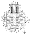
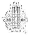
65は一側ハウジングブロック13の側面13Cに設けられた第1のポンプポートで、該第1のポンプポート65は、図2に示すように後述のカバー81Aよりも上側となる位置で側面13Cの中央部に開口し、後述する油圧ポンプ77の吐出側に接続されるものである。図6に示すように、第1のポンプポート65は、一側ハウジングブロック13内に穿設したポンプ通路66、センタバイパス通路67および高圧通路68,69等に連通している。   65 is a first pump port provided on the side surface 13C of the one-side housing block 13, and the first pump port 65 is located on the side surface 13C at a position above a cover 81A described later as shown in FIG. It opens to the center and is connected to the discharge side of a hydraulic pump 77 described later. As shown in FIG. 6, the first pump port 65 communicates with a pump passage 66, a center bypass passage 67, high-pressure passages 68 and 69, etc. that are formed in the one-side housing block 13.

ここで、センタバイパス通路67および高圧通路68は、図7、図14に示すようにポンプ通路66を介して第1のポンプポート65に連通している。また、高圧通路69は、図14の油圧回路にも示す通り、走行用制御弁26とバケット用制御弁34との間でセンタバイパス通路67の一側通路部67Aから分岐した通路であり、センタバイパス通路67の一側通路部67Aよりもハウジングブロック13の側面13Cに近い位置に配設されている(図6、図8、図9参照)。センタバイパス通路67および高圧通路69は、図6に示すように一側ハウジングブロック13から他側ハウジングブロック14内へと上,下方向(Z軸方向)に延びて形成されている。   Here, the center bypass passage 67 and the high pressure passage 68 communicate with the first pump port 65 via the pump passage 66 as shown in FIGS. Further, as shown in the hydraulic circuit of FIG. 14, the high-pressure passage 69 is a passage branched from the one-side passage portion 67A of the center bypass passage 67 between the traveling control valve 26 and the bucket control valve 34. The bypass passage 67 is disposed at a position closer to the side surface 13C of the housing block 13 than the one-side passage portion 67A (see FIGS. 6, 8, and 9). As shown in FIG. 6, the center bypass passage 67 and the high-pressure passage 69 are formed to extend upward and downward (Z-axis direction) from the one-side housing block 13 into the other-side housing block 14.

図6、図14に示すように、センタバイパス通路67は、一側ハウジングブロック13内に形成され上,下方向に延びた第1の一側通路部67Aと、他側ハウジングブロック14内に形成され上,下方向に延びた第1の他側通路部67Bと、これらの通路部67A,67B間を合せ面13B,14Aの位置で連通させる接続ポート67Cとを含んで構成されている。この接続ポート67Cにより、センタバイパス通路67の通路部67A,67B間は、図6に示す如く合せ面13B,14Aの上,下で液密に接続される。   As shown in FIGS. 6 and 14, the center bypass passage 67 is formed in the one-side housing block 13 and is formed in the first one-side passage portion 67 </ b> A that extends upward and downward and in the other-side housing block 14. The first other-side passage portion 67B extending upward and downward, and a connection port 67C for communicating the passage portions 67A and 67B at the positions of the mating surfaces 13B and 14A are included. By this connection port 67C, the passage portions 67A and 67B of the center bypass passage 67 are liquid-tightly connected above and below the mating surfaces 13B and 14A as shown in FIG.

また、高圧通路69は、一側ハウジングブロック13内に形成され上,下方向に延びた第1の一側通路部69Aと、他側ハウジングブロック14内に形成され上,下方向に延びた第1の他側通路部69Bと、これらの通路部69A,69B間を合せ面13B,14Aの位置で連通させる接続ポート69Cとを含んで構成されている。この接続ポート69Cにより、高圧通路69の通路部69A,69B間は合せ面13B,14Aの上,下で液密に接続されている。センタバイパス通路67の接続ポート67Cと高圧通路69の接続ポート69Cは、図13に示すように、他側ハウジングブロック14の4隅側に設ける4個のボルト16および低圧側油通路(即ち、後述する低圧通路70の各側方通路部70Bとタンク通路76の各側方通路部76B)よりも合せ面14Aの中央側寄りの位置に配置されている。   The high-pressure passage 69 is formed in the first housing block 13 and extends upward and downward, and the first high-pressure passage 69A is formed in the other housing block 14 and extends upward and downward. The other side passage portion 69B and a connection port 69C for communicating between the passage portions 69A and 69B at the positions of the mating surfaces 13B and 14A. By this connection port 69C, the passage portions 69A and 69B of the high-pressure passage 69 are liquid-tightly connected above and below the mating surfaces 13B and 14A. As shown in FIG. 13, the connection port 67C of the center bypass passage 67 and the connection port 69C of the high pressure passage 69 are provided with four bolts 16 and low pressure side oil passages (that will be described later) provided at the four corners of the other side housing block 14. The side passage portions 70B of the low pressure passage 70 and the side passage portions 76B) of the tank passage 76 are arranged at positions closer to the center of the mating surface 14A.

ここで、ポンプ通路66、高圧通路69は、第1の油圧ポンプ77から吐出される圧油を走行用制御弁26、バケット用制御弁34、ブーム用制御弁47、アーム用制御弁54等に供給する油圧源側油通路の高圧側を構成している。高圧通路69の一側通路部69Aは、その上流側が図14に示すように、走行用制御弁26とバケット用制御弁34との間でセンタバイパス通路67の一側通路部67Aから分岐し、下流側が接続ポート69Cの位置まで延びた第1の一側油通路系統を構成している。   Here, the pump passage 66 and the high-pressure passage 69 pass the pressure oil discharged from the first hydraulic pump 77 to the travel control valve 26, the bucket control valve 34, the boom control valve 47, the arm control valve 54, and the like. The high pressure side of the hydraulic source side oil passage to be supplied is configured. As shown in FIG. 14, the one-side passage portion 69A of the high-pressure passage 69 branches from the one-side passage portion 67A of the center bypass passage 67 between the traveling control valve 26 and the bucket control valve 34, as shown in FIG. A first one-side oil passage system in which the downstream side extends to the position of the connection port 69C is configured.

高圧通路69の一側通路部69Aは、その上流側が合せ面13B,14A間の接続ポート69Cに連通し、下流側がブーム用制御弁47とアーム用制御弁54とに並列接続された第1の他側油通路系統を構成している。即ち、高圧通路69の一側通路部69Aは、一側ハウジングブロック13の合せ面13Bに近い位置に配置されたバケット用制御弁34(スプール35)よりも上流側となる位置から合せ面13B,14A間の接続ポート69Cを通じて、第1の他側通路部69Bおよび制御弁47,54(スプール49,56)に第1の油圧ポンプ77からの圧油を供給する。   One side passage portion 69A of the high-pressure passage 69 communicates with the connection port 69C between the mating surfaces 13B and 14A on the upstream side, and the first side passage portion 69A is connected in parallel to the boom control valve 47 and the arm control valve 54. The other side oil passage system is configured. That is, the one-side passage portion 69A of the high-pressure passage 69 is aligned with the mating surfaces 13B, 13B from the position upstream of the bucket control valve 34 (spool 35) disposed near the mating surface 13B of the one-side housing block 13. Pressure oil from the first hydraulic pump 77 is supplied to the first other-side passage portion 69B and the control valves 47 and 54 (spools 49 and 56) through the connection port 69C between 14A.

70は一側ハウジングブロック13内に形成された低圧通路で、該低圧通路70は、図4〜図9に示すように、ポンプ通路66、センタバイパス通路67および高圧通路68,69から離間した位置に形成されている。低圧通路70は、一側ハウジングブロック13の上面13Aに沿って延びる複数(2本)の上側通路部70Aと、上端側が該各上側通路部70Aに連通し一側ハウジングブロック13の左,右の側面13E,13Fに沿って下向きに延びる左,右の側方通路部70Bとを含んで構成されている。   70 is a low-pressure passage formed in the one-side housing block 13, and the low-pressure passage 70 is located away from the pump passage 66, the center bypass passage 67, and the high-pressure passages 68 and 69, as shown in FIGS. Is formed. The low-pressure passage 70 includes a plurality (two) of upper passage portions 70A extending along the upper surface 13A of the one-side housing block 13 and upper and left ends of the one-side housing block 13 that communicate with the upper passage portions 70A. The left and right side passage portions 70B extend downward along the side surfaces 13E and 13F.

低圧通路70の各側方通路部70Bは、その下端側が合せ面13Bの位置で後述するタンク通路76の各側方通路部76Bと連通している。このため、低圧通路70の上側通路部70Aおよび側方通路部70B内を流れる油液(各油圧アクチュエータからの戻り油)は、後述のタンク78にタンク通路76を介して排出されるものである。   Each side passage portion 70B of the low-pressure passage 70 communicates with each side passage portion 76B of the tank passage 76 described later at the position of the mating surface 13B. Therefore, the oil liquid (return oil from each hydraulic actuator) flowing in the upper passage portion 70A and the side passage portion 70B of the low pressure passage 70 is discharged to the tank 78 described later via the tank passage 76. .

71は他側ハウジングブロック14の側面14Cに設けられた第2のポンプポートで、該第2のポンプポート71は、図2に示すように後述のカバー85Aよりも下側となる位置で側面14Cの中央部に開口し、後述する第2の油圧ポンプ79の吐出側に接続されるものである。第2のポンプポート71は、他側ハウジングブロック14内に穿設したポンプ通路72に連通すると共に、他側ハウジングブロック14から一側ハウジングブロック13にわたって、例えばZ軸方向に延びるように形成されたセンタバイパス通路73および高圧通路74にも連通している。   Reference numeral 71 denotes a second pump port provided on the side surface 14C of the other housing block 14, and the second pump port 71 is located on the side surface 14C at a position below a cover 85A described later as shown in FIG. And is connected to the discharge side of a second hydraulic pump 79 described later. The second pump port 71 communicates with a pump passage 72 formed in the other housing block 14 and extends from the other housing block 14 to the one housing block 13, for example, in the Z-axis direction. The center bypass passage 73 and the high pressure passage 74 are also communicated.

ここで、高圧通路74は、図14の油圧回路にも示す通り、旋回用制御弁61よりも上流側となる位置でポンプ通路72から分岐し、この分岐位置でセンタバイパス通路73はポンプ通路72に接続されている。また、高圧通路74は、図6に示すように、センタバイパス通路73よりもハウジングブロック13,14の側面13D,14Dに近い位置に配設されている。センタバイパス通路73および高圧通路74は、他側ハウジングブロック14から一側ハウジングブロック13内へと上向きに延びて形成されている。   Here, as shown in the hydraulic circuit of FIG. 14, the high pressure passage 74 branches from the pump passage 72 at a position upstream of the turning control valve 61, and the center bypass passage 73 is connected to the pump passage 72 at this branch position. It is connected to the. Further, as shown in FIG. 6, the high pressure passage 74 is disposed at a position closer to the side surfaces 13 </ b> D and 14 </ b> D of the housing blocks 13 and 14 than the center bypass passage 73. The center bypass passage 73 and the high pressure passage 74 are formed to extend upward from the other housing block 14 into the one housing block 13.

図6、図14に示すように、センタバイパス通路73は、一側ハウジングブロック13内に形成され上,下方向に延びた第2の一側通路部73Aと、他側ハウジングブロック14内に形成され上,下方向に延びた第2の他側通路部73Bと、これらの通路部73A,73B間を合せ面13B,14Aの位置で連通させる接続ポート73Cとを含んで構成されている。この接続ポート73Cにより、センタバイパス通路73の通路部73A,73B間は、図6に示す如く合せ面13B,14Aの上,下で液密に接続される。   As shown in FIGS. 6 and 14, the center bypass passage 73 is formed in the second housing block 14 and the second first passage portion 73 </ b> A formed in the first housing block 13 and extending upward and downward. The second other passage portion 73B extending upward and downward, and a connection port 73C for communicating between the passage portions 73A and 73B at the positions of the mating surfaces 13B and 14A are configured. By this connection port 73C, the passage portions 73A and 73B of the center bypass passage 73 are liquid-tightly connected above and below the mating surfaces 13B and 14A as shown in FIG.

第2の油圧ポンプ79に接続される高圧通路74は、一側ハウジングブロック13内に形成され上,下方向に延びた第2の一側通路部74Aと、他側ハウジングブロック14内に形成され上,下方向に延びた第2の他側通路部74Bと、これらの通路部74A,74B間を合せ面13B,14Aの位置で連通させる接続ポート74Cとを含んで構成されている。この接続ポート74Cにより、高圧通路74の通路部74A,74B間は、図6に示す如く合せ面13B,14Aの上,下で液密に接続される。センタバイパス通路73の接続ポート73Cと高圧通路74の接続ポート74Cは、図13に示すように、他側ハウジングブロック14の4隅側に設ける4個のボルト16および低圧側油通路(即ち、低圧通路70の各側方通路部70Bと後述するタンク通路76の各側方通路部76B)よりも合せ面14Aの中央側寄りの位置に配置されている。   The high-pressure passage 74 connected to the second hydraulic pump 79 is formed in the second housing block 14 and the second first passage portion 74A formed in the first housing block 13 and extending upward and downward. A second other passage portion 74B extending in the upward and downward directions and a connection port 74C for communicating between the passage portions 74A and 74B at the positions of the mating surfaces 13B and 14A are configured. By this connection port 74C, the passage portions 74A and 74B of the high-pressure passage 74 are liquid-tightly connected above and below the mating surfaces 13B and 14A as shown in FIG. As shown in FIG. 13, the connection port 73C of the center bypass passage 73 and the connection port 74C of the high pressure passage 74 have four bolts 16 and low pressure side oil passages (that is, low pressure side passages) provided at the four corners of the other side housing block 14. Each side passage portion 70B of the passage 70 and each side passage portion 76B of the tank passage 76 described later are disposed at positions closer to the center side of the mating surface 14A.

ポンプ通路72、高圧通路74は、後述する第2の油圧ポンプ79から吐出された圧油を、旋回用制御弁61、アーム用制御弁55、ブーム用制御弁48、予備の制御弁38、走行用制御弁30等に供給する油圧源側油通路の高圧側を構成している。高圧通路74の一側通路部74Aは、その上流側が合せ面13B,14A間の接続ポート74Cに連通し、下流側が予備の制御弁38と走行用制御弁30とに並列接続されてスプール39,31に第2の油圧ポンプ79からの圧油を供給する第2の一側油通路系統を構成している。   The pump passage 72 and the high-pressure passage 74 are configured to send pressure oil discharged from a second hydraulic pump 79, which will be described later, to the turning control valve 61, the arm control valve 55, the boom control valve 48, the spare control valve 38, and the travel. The high pressure side of the oil pressure source side oil passage supplied to the control valve 30 or the like is configured. The one-side passage portion 74A of the high-pressure passage 74 communicates with the connection port 74C between the mating surfaces 13B and 14A on the upstream side, and is connected in parallel to the spare control valve 38 and the travel control valve 30 on the downstream side. A second one-side oil passage system that supplies pressure oil from the second hydraulic pump 79 to the cylinder 31 is configured.

高圧通路74の他側通路部74Bは、その上流側が図14に示すように、旋回用制御弁61の手前位置(制御弁61よりも上流側となる位置)でセンタバイパス通路73の他側通路部73Bから分岐し、下流側が接続ポート74Cの位置まで延びた第2の他側油通路系統を構成している。他側通路部74Bの下流側は、アーム用制御弁55とブーム用制御弁48とに並列接続され、スプール58,51に第2の油圧ポンプ79からの圧油を供給する。   As shown in FIG. 14, the other side passage portion 74B of the high pressure passage 74 is located on the upstream side of the turning control valve 61 (the position upstream of the control valve 61). The second other-side oil passage system is branched from the portion 73B and the downstream side extends to the position of the connection port 74C. The downstream side of the other-side passage portion 74B is connected in parallel to the arm control valve 55 and the boom control valve 48, and supplies pressure oil from the second hydraulic pump 79 to the spools 58 and 51.

換言すると、一側ハウジングブロック13には、複数の油圧源側油通路の高圧側が第1の油圧ポンプ77に接続される一側通路部69Aからなる第1の一側油通路系統と、第2の油圧ポンプ79に接続される一側通路部74Aからなる第2の一側油通路系統とに分離して形成されている。また、他側ハウジングブロック14には、複数の油圧源側油通路の高圧側が第1の油圧ポンプ77に接続される他側通路部69Bからなる第1の他側油通路系統と、第2の油圧ポンプ79に接続される他側通路部74Bからなる第2の他側油通路系統とに分離して形成されている。   In other words, the one-side housing block 13 includes a first one-side oil passage system including a one-side passage portion 69 </ b> A in which the high-pressure sides of the plurality of hydraulic source-side oil passages are connected to the first hydraulic pump 77, and the second The second one-side oil passage system including the one-side passage portion 74A connected to the hydraulic pump 79 is formed separately. The other housing block 14 includes a first other-side oil passage system including an other-side passage portion 69B in which the high-pressure sides of the plurality of oil-source-side oil passages are connected to the first hydraulic pump 77, and a second It is formed separately from the second other-side oil passage system composed of the other-side passage portion 74B connected to the hydraulic pump 79.

一側ハウジングブロック13に形成された第1の一側油通路系統(一側通路部69A)は、他側ハウジングブロック14に形成された第1の他側油通路系統(他側通路部69B)に合せ面13B,14A間の接続ポート69Cを通じて連通している。一側ハウジングブロック13に形成された第2の一側油通路系統(一側通路部74A)は、他側ハウジングブロック14に形成された第2の他側油通路系統(他側通路部74B)に合せ面13B,14A間の接続ポート74Cを通じて連通している。   A first one-side oil passage system (one-side passage portion 69A) formed in the one-side housing block 13 is a first other-side oil passage system (other-side passage portion 69B) formed in the other-side housing block 14. Are connected through a connection port 69C between the mating surfaces 13B and 14A. A second one-side oil passage system (one-side passage portion 74A) formed in the one-side housing block 13 is a second other-side oil passage system (other-side passage portion 74B) formed in the other-side housing block 14. Are connected through a connection port 74C between the mating surfaces 13B and 14A.

75は他側ハウジングブロック14の側面14Cに設けられたタンクポートで、該タンクポート75は、図2に示すように第2のポンプポート71から左方向に離間した位置で側面14Cに開口し、後述のタンク78に接続されるものである。低圧通路としてのタンク通路76は、図12、図14に示すように下側通路部76Aと左,右の側方通路部76Bとを有している。タンクポート75は、タンク通路76の下側通路部76Aを介して左,右の側方通路部76B等に連通し、これらの側方通路部76B内を流れる油液(各油圧アクチュエータからの戻り油)をタンク78に排出するものである。   75 is a tank port provided on the side surface 14C of the other housing block 14, and the tank port 75 opens to the side surface 14C at a position spaced leftward from the second pump port 71 as shown in FIG. It is connected to a tank 78 described later. The tank passage 76 as a low pressure passage has a lower passage portion 76A and left and right side passage portions 76B as shown in FIGS. The tank port 75 communicates with the left and right side passage portions 76B through the lower passage portion 76A of the tank passage 76, and the oil liquid (return from each hydraulic actuator) that flows in the side passage portions 76B. Oil) is discharged into a tank 78.

ここで、各側方通路部76Bは、例えば図4、図5に示す如く他側ハウジングブロック14内で左,右(X軸方向)大きく離間して形成されている。そして、これらの側方通路部76Bは、一側ハウジングブロック13内に形成した前記低圧通路70の側方通路部70Bと合せ面13B,14Aの位置で液密に接続されている。側方通路部70B,76B間を流通する油液(戻り油)は低圧であるため、合せ面13B,14Aの位置で油漏れ(リーク)が生じることは少ない。   Here, as shown in FIGS. 4 and 5, for example, the side passage portions 76B are formed to be greatly separated from each other in the left and right sides (X-axis direction) in the other-side housing block 14. These side passage portions 76B are liquid-tightly connected to the side passage portions 70B of the low-pressure passage 70 formed in the one-side housing block 13 at the positions of the mating surfaces 13B and 14A. Since the oil liquid (return oil) flowing between the side passage portions 70B and 76B is at a low pressure, there is little oil leakage (leak) at the positions of the mating surfaces 13B and 14A.

77はタンク78と共に第1の油圧源を構成する第1の油圧ポンプで、該第1の油圧ポンプ77は、その吐出側が図6、図7に示すように第1のポンプポート65に接続され、ポンプ通路66および高圧通路69等を介して制御弁26,34,47,54(スプール27,35,49,56)等に圧油を供給するものである。   Reference numeral 77 denotes a first hydraulic pump that constitutes a first hydraulic power source together with the tank 78. The discharge side of the first hydraulic pump 77 is connected to the first pump port 65 as shown in FIGS. The pressure oil is supplied to the control valves 26, 34, 47, 54 (spools 27, 35, 49, 56) through the pump passage 66 and the high pressure passage 69.

79はタンク78と共に第2の油圧源を構成する第2の油圧ポンプで、該第2の油圧ポンプ79は、その吐出側が図6、図12に示すように第2のポンプポート71に接続され、ポンプ通路72および高圧通路74等を介して制御弁61,55,48,38,30(スプール62,58,51,39,31)等に圧油を供給するものである。   Reference numeral 79 denotes a second hydraulic pump that constitutes a second hydraulic power source together with the tank 78. The discharge side of the second hydraulic pump 79 is connected to the second pump port 71 as shown in FIGS. The pressure oil is supplied to the control valves 61, 55, 48, 38, 30 (spools 62, 58, 51, 39, 31) through the pump passage 72 and the high pressure passage 74.

80は走行用制御弁30に付設したチェック弁で、該チェック弁80は、図7に示す如くハウジングブロック13の側面13Dから高圧通路74側に向けて装入するように取付けられ、側面13Dとの間はカバー80Aによって閉塞されている。チェック弁80は、高圧通路74から油溝19C側に向けて圧油が流通するのを許し、逆向きの流れを阻止するものである。   80 is a check valve attached to the travel control valve 30. The check valve 80 is mounted so as to be inserted from the side surface 13D of the housing block 13 toward the high pressure passage 74 as shown in FIG. Is closed by the cover 80A. The check valve 80 allows pressure oil to flow from the high-pressure passage 74 toward the oil groove 19 </ b> C, and prevents reverse flow.

81はバケット用制御弁34に付設したチェック弁で、該チェック弁81は、図8に示す如くハウジングブロック13の側面13Cから高圧通路69側に向けて装入するように取付けられ、側面13Cとの間はカバー81Aによって閉塞されている。チェック弁81は、高圧通路69から油溝20C側に向けて圧油が流通するのを許し、逆向きの流れを阻止するものである。   81 is a check valve attached to the bucket control valve 34. The check valve 81 is attached so as to be inserted from the side surface 13C of the housing block 13 toward the high pressure passage 69 as shown in FIG. Is closed by a cover 81A. The check valve 81 allows the pressure oil to flow from the high-pressure passage 69 toward the oil groove 20 </ b> C, and prevents a reverse flow.

82は予備の制御弁38に付設した他のチェック弁で、該チェック弁82は、前述したチェック弁80とほぼ同様に構成され、ハウジングブロック13の側面13D側にカバー82Aが設けられている。チェック弁82は、高圧通路74から油溝21C側に向けて圧油が流通するのを許し、逆向きの流れを阻止するものである。   Reference numeral 82 denotes another check valve attached to the spare control valve 38. The check valve 82 is configured in substantially the same manner as the above-described check valve 80, and a cover 82A is provided on the side surface 13D side of the housing block 13. The check valve 82 allows the pressure oil to flow from the high-pressure passage 74 toward the oil groove 21 </ b> C, and prevents a reverse flow.

また、他側ハウジングブロック14にも、チェック弁83〜87が設けられている。このうちチェック弁83,84は、図16に示す如くブーム用制御弁47,48に付設され、これらのチェック弁83,84はカバー83A,84Aを備えている。一方、チェック弁85,86は、図11に示すようにアーム用制御弁54,55に付設され、これらのチェック弁85,86はカバー85A,86Aを備えている。さらに、チェック弁87は、図12に示すように旋回用制御弁61に付設され、チェック弁87はカバー87Aを備えている。   The other side housing block 14 is also provided with check valves 83 to 87. Among these, the check valves 83 and 84 are attached to the boom control valves 47 and 48 as shown in FIG. 16, and these check valves 83 and 84 are provided with covers 83A and 84A. On the other hand, the check valves 85 and 86 are attached to the arm control valves 54 and 55 as shown in FIG. 11, and these check valves 85 and 86 are provided with covers 85A and 86A. Furthermore, the check valve 87 is attached to the turning control valve 61 as shown in FIG. 12, and the check valve 87 includes a cover 87A.

88は一側ハウジングブロック13に設けられたメインのリリーフ弁で、該リリーフ弁88は、図9、図14に示すように、一対のチェック弁89,90間に位置して一側ハウジングブロック13に取付けられている。図9に示すように、チェック弁89は、高圧通路68に連通したリリーフ通路91を閉塞するように、弁ばね89Aにより常時閉弁方向に付勢されている。リリーフ通路91内の圧力が弁ばね89Aの設定圧を越えると、チェック弁89は開弁し、リリーフ弁88の圧力室88Aには、高圧通路68内の圧力がリリーフ通路91を介して導かれる。しかし、チェック弁89は、圧力室88Aからリリーフ通路91側に向けて油液が流通するのを阻止する。   88 is a main relief valve provided in the one-side housing block 13, and the relief valve 88 is located between the pair of check valves 89, 90 as shown in FIGS. 9 and 14. Installed on. As shown in FIG. 9, the check valve 89 is always urged in the valve closing direction by the valve spring 89 </ b> A so as to close the relief passage 91 communicating with the high pressure passage 68. When the pressure in the relief passage 91 exceeds the set pressure of the valve spring 89A, the check valve 89 is opened, and the pressure in the high pressure passage 68 is guided to the pressure chamber 88A of the relief valve 88 via the relief passage 91. . However, the check valve 89 prevents the oil liquid from flowing from the pressure chamber 88A toward the relief passage 91 side.

また、チェック弁90は、高圧通路74に連通したリリーフ通路92を閉塞するように、弁ばね90Aにより常時閉弁方向に付勢されている。リリーフ通路92内の圧力が弁ばね90Aの設定圧を越えると、チェック弁90は開弁し、リリーフ弁88の圧力室88Aには、高圧通路74内の圧力がリリーフ通路92を介して導かれる。しかし、チェック弁90は、圧力室88Aからリリーフ通路92側に向けて油液が流通するのを阻止するものである。   The check valve 90 is always urged in the valve closing direction by the valve spring 90A so as to close the relief passage 92 communicating with the high pressure passage 74. When the pressure in the relief passage 92 exceeds the set pressure of the valve spring 90A, the check valve 90 opens, and the pressure in the high pressure passage 74 is guided to the pressure chamber 88A of the relief valve 88 through the relief passage 92. . However, the check valve 90 prevents the oil liquid from flowing from the pressure chamber 88A toward the relief passage 92 side.

リリーフ弁88は、圧力室88A(即ち、高圧通路68,74)内の圧力が所定のリリーフ設定圧を越えると開弁し、このときの過剰圧を低圧通路70の側方通路部70B等を介してタンク78側にリリーフさせる。これにより、リリーフ弁88は、ポンプ通路66,72および高圧通路68,69,74内の最高圧力を予め決められたリリーフ設定圧以下に抑えるものである。   The relief valve 88 opens when the pressure in the pressure chamber 88A (that is, the high pressure passages 68 and 74) exceeds a predetermined relief set pressure, and the excess pressure at this time is passed through the side passage portion 70B of the low pressure passage 70 and the like. And relief to the tank 78 side. Thereby, the relief valve 88 suppresses the maximum pressure in the pump passages 66, 72 and the high pressure passages 68, 69, 74 to a predetermined relief setting pressure or less.

ここで、リリーフ弁88は、図5に示す如く予備の制御弁38(スプール摺動穴21)よりも下側でハウジングブロック13の合せ面13Bに近い位置、即ちハウジングブロック13内に設けられたスプール摺動穴18〜21よりも合せ面13Bに近い位置に配設されている。これにより、リリーフ弁88は、例えば図14に例示するように第1のポンプポート65と第2のポンプポート71との間でほぼ中間となる位置(即ち、両者間の管路長をほぼ等しくできる位置)に配置されるものである。   Here, as shown in FIG. 5, the relief valve 88 is provided below the spare control valve 38 (spool sliding hole 21) and close to the mating surface 13B of the housing block 13, that is, in the housing block 13. It is disposed at a position closer to the mating surface 13B than the spool sliding holes 18-21. Thereby, for example, as shown in FIG. 14, the relief valve 88 is located at a substantially intermediate position between the first pump port 65 and the second pump port 71 (that is, the pipe line length between the two is almost equal. Position).

93A,93Bは他側ハウジングブロック14内でブーム用制御弁47,48間に設けられた合流通路で、該合流通路93A,93Bは、図10に示す如くブーム用制御弁47(スプール摺動穴42)の油溝42A,42Bとブーム用制御弁48(スプール摺動穴43)の油溝43A,43Bとの間を常時連通させる。合流通路93A,93Bは、油溝42A,42Bおよび油溝43A,43Bと共にブーム用制御弁47,48のアクチュエータ側油通路を構成している。合流通路93A,93Bは、第1,第2の油圧ポンプ77,79からブーム用制御弁47,48(ブーム用スプール49,51)に供給される圧油を互いに合流させ、合流した圧油を圧油給排ポート53A,53Bから作業装置7のブームシリンダ8Aに給排させる。   93A and 93B are merging passages provided between the boom control valves 47 and 48 in the other housing block 14, and the merging passages 93A and 93B are formed as shown in FIG. 42) and the oil grooves 43A and 43B of the boom control valve 48 (spool sliding hole 43) are always in communication. The merge passages 93A and 93B constitute the actuator side oil passages of the boom control valves 47 and 48 together with the oil grooves 42A and 42B and the oil grooves 43A and 43B. The joining passages 93A and 93B join together the pressure oil supplied from the first and second hydraulic pumps 77 and 79 to the boom control valves 47 and 48 (boom spools 49 and 51). The pressure oil supply / discharge ports 53A and 53B are supplied to and discharged from the boom cylinder 8A of the work device 7.

94A,94Bは他側ハウジングブロック14内でアーム用制御弁54,55間に設けられた合流通路で、該合流通路94A,94Bは、図11に示す如くアーム用制御弁54(スプール摺動穴44)の油溝44A,44Bとアーム用制御弁55(スプール摺動穴45)の油溝45A,45Bとの間を常時連通させる。合流通路94A,94Bは、油溝44A,44Bおよび油溝45A,45Bと共にアーム用制御弁54,55のアクチュエータ側油通路を構成している。合流通路94A,94Bは、第1,第2の油圧ポンプ77,79からアーム用制御弁54,55(アーム用スプール56,58)に供給される圧油を互いに合流させ、合流した圧油を圧油給排ポート60A,60Bから作業装置7のアームシリンダ9Aに給排させる。   94A and 94B are merging passages provided between the arm control valves 54 and 55 in the other side housing block 14, and these merging passages 94A and 94B are arm control valves 54 (spool sliding holes as shown in FIG. 11). 44) and the oil grooves 45A, 45B of the arm control valve 55 (spool sliding hole 45) are always in communication. The merging passages 94A and 94B constitute the actuator side oil passages of the arm control valves 54 and 55 together with the oil grooves 44A and 44B and the oil grooves 45A and 45B. The joining passages 94A and 94B join together the pressure oil supplied from the first and second hydraulic pumps 77 and 79 to the arm control valves 54 and 55 (arm spools 56 and 58). The pressure oil supply / discharge ports 60A and 60B are supplied to and discharged from the arm cylinder 9A of the work device 7.

本実施の形態による油圧ショベル1に搭載した多連弁装置11は、上述の如き構成を有するもので、次にその作動について説明する。   The multiple valve device 11 mounted on the hydraulic excavator 1 according to this embodiment has the above-described configuration, and the operation thereof will be described next.

まず、油圧ショベル1(車両)を走行させるときには、キャブ4内に搭乗したオペレータが左,右の走行用レバー等を傾転操作すると、このときのパイロット圧に従って左,右の走行用制御弁26,30が中立位置(イ)から切換位置(ロ),(ハ)のいずれかに切換えられる。   First, when the hydraulic excavator 1 (vehicle) travels, if the operator who has boarded the cab 4 tilts the left and right travel levers, the left and right travel control valves 26 according to the pilot pressure at this time. , 30 are switched from the neutral position (A) to any one of the switching positions (B), (C).

これにより、右側の走行用制御弁26は、油圧ポンプ77からの圧油を圧油給排ポート29A,29Bを介して右側の走行用モータ2Rに給排する。そして、左側の走行用制御弁30は、油圧ポンプ79からの圧油を圧油給排ポート33A,33Bを介して左側の走行用モータ2Lに給排する。この結果、下部走行体2は、左,右の走行用モータ2L,2Rで履帯を駆動し、車両を前進または後進させる走行動作を行うことができる。   Thus, the right travel control valve 26 supplies and discharges the pressure oil from the hydraulic pump 77 to the right travel motor 2R via the pressure oil supply / discharge ports 29A and 29B. The left travel control valve 30 supplies and discharges the pressure oil from the hydraulic pump 79 to the left travel motor 2L via the pressure oil supply / discharge ports 33A and 33B. As a result, the lower traveling body 2 can perform a traveling operation in which the crawler belt is driven by the left and right traveling motors 2L and 2R to move the vehicle forward or backward.

また、作業現場において土砂等の掘削作業を行うときには、作業装置7のブーム8とアーム9を上,下に俯仰動させつつ、バケット10を回動する。即ち、キャブ4内のオペレータがバケット用操作レバーを傾転操作することにより、バケット用制御弁34が中立位置(イ)から切換位置(ロ),(ハ)のいずれかに切換えられ、第1の油圧ポンプ77からの圧油をバケット用制御弁34、圧油給排ポート37A,37Bを介してバケットシリンダ10Aに給排する。   Further, when excavation work such as earth and sand is performed at the work site, the bucket 10 is rotated while the boom 8 and the arm 9 of the working device 7 are moved up and down. That is, when the operator in the cab 4 tilts the bucket operation lever, the bucket control valve 34 is switched from the neutral position (A) to any one of the switching positions (B) and (C). The pressure oil from the hydraulic pump 77 is supplied / discharged to / from the bucket cylinder 10A via the bucket control valve 34 and the pressure oil supply / discharge ports 37A, 37B.

ブーム用操作レバーが傾転されると、ブーム用制御弁47,48が中立位置(イ)から切換位置(ロ),(ハ)のいずれかに切換えられる。これにより、第1,第2の油圧ポンプ77,79から吐出された圧油は、ブーム用制御弁47,48により合流通路93A,93Bを介して互いに合流され、合流された圧油を圧油給排ポート53A,53Bを介してブームシリンダ8Aに給排することができる。   When the boom control lever is tilted, the boom control valves 47 and 48 are switched from the neutral position (A) to any one of the switching positions (B) and (C). Thus, the pressure oil discharged from the first and second hydraulic pumps 77 and 79 is joined to each other via the joining passages 93A and 93B by the boom control valves 47 and 48, and the joined pressure oil is used as the pressure oil. The boom cylinder 8A can be supplied and discharged via the supply / discharge ports 53A and 53B.

また、アーム用操作レバーが傾転されると、アーム用制御弁54,55が中立位置(イ)から切換位置(ロ),(ハ)のいずれかに切換えられる。これにより、第1,第2の油圧ポンプ77,79から吐出された圧油は、アーム用制御弁54,55により合流通路94A,94Bを介して互いに合流され、合流された圧油を圧油給排ポート60A,60Bを介してアームシリンダ9Aに給排することができる。   When the arm operation lever is tilted, the arm control valves 54 and 55 are switched from the neutral position (A) to any one of the switching positions (B) and (C). As a result, the pressure oil discharged from the first and second hydraulic pumps 77 and 79 are joined together by the arm control valves 54 and 55 via the joining passages 94A and 94B, and the joined pressure oil is used as the pressure oil. The arm cylinder 9A can be supplied / discharged via the supply / discharge ports 60A, 60B.

また、下部走行体2上で上部旋回体3を旋回駆動するときには、旋回用操作レバーの傾転操作に従って旋回用制御弁61を中立位置(イ)から切換位置(ロ),(ハ)のいずれかに切換える。これにより、第2の油圧ポンプ79から吐出された圧油を、旋回用制御弁61、圧油給排ポート64A,64Bを介して旋回用モータ3Mに給排でき、旋回用モータ3Mを旋回駆動することができる。   When the upper swing body 3 is driven to turn on the lower traveling body 2, the turning control valve 61 is moved from the neutral position (A) to the switching position (B) or (C) according to the tilting operation of the turning operation lever. Switch to Thus, the pressure oil discharged from the second hydraulic pump 79 can be supplied to and discharged from the turning motor 3M through the turning control valve 61 and the pressure oil supply / discharge ports 64A and 64B, and the turning motor 3M is driven to turn. can do.

ところで、図15に示す比較例のように、多連弁装置11′の弁ハウジング12′を2分割型とする場合に、左,右方向(例えば、Y軸方向)で2分割した左ハウジングブロック13′,右ハウジングブロック14′を用いることがある。図15に示す左ハウジングブロック13′と右ハウジングブロック14′とは、例えば上,下方向(Z軸方向)に延びる合せ面13B′,14A′の位置で互いに分離可能に衝合されている。   By the way, when the valve housing 12 'of the multiple valve device 11' is divided into two parts as in the comparative example shown in FIG. 15, the left housing block is divided into two parts in the left and right directions (for example, the Y-axis direction). 13 ', right housing block 14' may be used. The left housing block 13 ′ and the right housing block 14 ′ shown in FIG. 15 abut against each other at positions of mating surfaces 13 B ′ and 14 A ′ extending in the upward and downward directions (Z-axis direction), for example.

しかし、図15に示す比較例にあっては、左ハウジングブロック13′内と右ハウジングブロック14′内とに設けるスプールの個数を増やすために、各ハウジングブロック13′,14′の寸法を大きくすると、合せ面13B′,14A′の面積を広くせざるを得ず、合せ面13B′,14A′の位置でシール不良、油漏れ等が発生する可能性が高くなる。   However, in the comparative example shown in FIG. 15, in order to increase the number of spools provided in the left housing block 13 'and the right housing block 14', the size of each housing block 13 ', 14' is increased. Therefore, the area of the mating surfaces 13B 'and 14A' must be increased, and the possibility of occurrence of poor sealing and oil leakage at the positions of the mating surfaces 13B 'and 14A' increases.

しかも、油圧源として第1,第2の油圧ポンプ77,79を用い、ブームシリンダ8Aとアームシリンダ9Aとに2つの油圧ポンプ77,79からの圧油を合流させて供給する場合に、ブーム用制御弁47,48間では、合流通路93A,93Bを合せ面13B′,14A′の位置でそれぞれ2分割し、両者の間を接続ポート93A′,93B′により連通させる。アーム用制御弁54,55間では合流通路94A,94Bを合せ面13B′,14A′の位置でそれぞれ2分割し、両者の間を接続ポート94A′,94B′により連通させる。   In addition, when the first and second hydraulic pumps 77 and 79 are used as the hydraulic source and the pressure oil from the two hydraulic pumps 77 and 79 is supplied to the boom cylinder 8A and the arm cylinder 9A to be supplied, the boom Between the control valves 47 and 48, the joining passages 93A and 93B are respectively divided into two at the positions of the mating surfaces 13B 'and 14A', and the two are communicated by the connection ports 93A 'and 93B'. Between the arm control valves 54 and 55, the joining passages 94A and 94B are respectively divided into two at the positions of the mating surfaces 13B 'and 14A', and the two are communicated by connection ports 94A 'and 94B'.

これにより、ハウジングブロック13′,14′の合せ面13B′,14A′の位置には、合計4個の接続ポート93A′,93B′,94A′,94B′が形成されることになる。さらに、リリーフ弁88に対して第1の油圧ポンプ77からの圧油を導く高圧通路68には、チェック弁89の下流側で合せ面13B′,14A′の位置に接続ポート68′が形成され、第2のポンプポート71に連通するポンプ通路72にも、合せ面13B′,14A′の位置に接続ポート72′が形成される。   As a result, a total of four connection ports 93A ', 93B', 94A ', 94B' are formed at the positions of the mating surfaces 13B ', 14A' of the housing blocks 13 ', 14'. Further, a connection port 68 ′ is formed at the position of the mating surfaces 13 B ′ and 14 A ′ in the high pressure passage 68 that guides the pressure oil from the first hydraulic pump 77 to the relief valve 88 on the downstream side of the check valve 89. A connection port 72 ′ is also formed at the position of the mating surfaces 13 B ′ and 14 A ′ in the pump passage 72 communicating with the second pump port 71.

このように、図15に示す比較例では、左ハウジングブロック13′と右ハウジングブロック14′との間に介在する合せ面13B′,14A′の位置に、合計6個の接続ポート68′,72′,93A′,93B′,94A′,94B′が形成される。これによって、合せ面13B′,14A′における圧油の合流箇所が6箇所に増えるために、油漏れが発生する可能性が高くなってしまう。   Thus, in the comparative example shown in FIG. 15, a total of six connection ports 68 ′, 72 are provided at the positions of the mating surfaces 13B ′, 14A ′ interposed between the left housing block 13 ′ and the right housing block 14 ′. ', 93A', 93B ', 94A', 94B 'are formed. As a result, the number of pressure oil merging points on the mating surfaces 13B ′ and 14A ′ increases to six, and the possibility of oil leakage increases.

そこで、第1の実施の形態は、このような問題を解決するために、多連弁装置11の弁ハウジング12を上,下方向(例えば、Z軸方向)で一側ハウジングブロック13と他側ハウジングブロック14に2分割して形成する構成とし、該一側ハウジングブロック13と他側ハウジングブロック14は、相手方と上,下方向で対向する合せ面13B,14Aの位置で互いに衝合、離間される構成としている。   Therefore, in the first embodiment, in order to solve such a problem, the valve housing 12 of the multiple valve device 11 is moved upward and downward (for example, in the Z-axis direction) from the one-side housing block 13 and the other side. The housing block 14 is divided into two, and the one-side housing block 13 and the other-side housing block 14 are abutted and separated from each other at the positions of the mating surfaces 13B and 14A facing the other side in the upward and downward directions. The configuration is as follows.

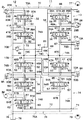
このため、一側ハウジングブロック13と他側ハウジングブロック14との間の合せ面13B,14Aの位置には、図14に示すように合計4個の接続ポート67C,69C,73C,74Cを設けるだけで、第1,第2の油圧ポンプ77,79からの圧油を全ての制御弁26,30,34,38,47,48,54,55,61(スプール27,31,35,39,49,51,56,58,62)に供給することができ、接続ポート67C,69C,73C,74Cの数を必要最小限に減らし、合せ面13B,14A間における油漏れ等の発生を抑えることができる。   Therefore, a total of four connection ports 67C, 69C, 73C, and 74C are provided at the positions of the mating surfaces 13B and 14A between the one-side housing block 13 and the other-side housing block 14 as shown in FIG. Thus, the pressure oil from the first and second hydraulic pumps 77, 79 is supplied to all the control valves 26, 30, 34, 38, 47, 48, 54, 55, 61 (spools 27, 31, 35, 39, 49). 51, 56, 58, 62), the number of connection ports 67C, 69C, 73C, 74C can be reduced to the minimum necessary, and the occurrence of oil leakage between the mating surfaces 13B, 14A can be suppressed. it can.

即ち、第1の油圧ポンプ77からの圧油をセンタバイパス通路67の一側通路部67A、高圧通路69の一側通路部69A(第1の一側油通路系統)を介して一側ハウジングブロック13内の制御弁26,34(スプール27,35)に供給できると共に、第1の油圧ポンプ77からの圧油を合せ面13B,14Aの接続ポート69Cを通じて他側ハウジングブロック14の他側通路部69B(第1の他側油通路系統)に供給し、他側ハウジングブロック14内の制御弁47,54(スプール49,56)に供給することができる。   That is, the pressure oil from the first hydraulic pump 77 is supplied to the one-side housing block via the one-side passage portion 67A of the center bypass passage 67 and the one-side passage portion 69A (first one-side oil passage system) of the high-pressure passage 69. 13 can be supplied to the control valves 26 and 34 (spools 27 and 35) in the engine 13, and the pressure oil from the first hydraulic pump 77 can be supplied to the other side passage portion of the other side housing block 14 through the connection port 69C of the mating surfaces 13B and 14A. 69B (first other-side oil passage system) can be supplied to control valves 47 and 54 (spools 49 and 56) in the other-side housing block 14.

第2の油圧ポンプ79からの圧油は、センタバイパス通路73の他側通路部73B、高圧通路74の他側通路部74B(第2の他側油通路系統)を介して他側ハウジングブロック14内の制御弁61,55,48(スプール62,58,51)に供給できると共に、第2の油圧ポンプ79からの圧油を合せ面13B,14Aの接続ポート74Cを通じて一側ハウジングブロック13の一側通路部74A(第2の一側油通路系統)にも供給し、制御弁38,30(スプール39,31)に供給することができる。   The pressure oil from the second hydraulic pump 79 passes through the other side housing block 14 via the other side passage 73B of the center bypass passage 73 and the other side passage 74B (second other oil passage system) of the high pressure passage 74. Can be supplied to the control valves 61, 55, and 48 (spools 62, 58, and 51), and pressure oil from the second hydraulic pump 79 can be supplied to the one side housing block 13 through the connection port 74C of the mating surfaces 13B and 14A. It can also be supplied to the side passage portion 74A (second one-side oil passage system) and supplied to the control valves 38 and 30 (spools 39 and 31).

また、ブームシリンダ8Aを制御するブーム用制御弁47,48(ブーム用スプール49,51)は、同じ他側ハウジングブロック14内に設けているので、第1,第2の油圧ポンプ77,79から吐出される圧油を一つの他側ハウジングブロック14内(合流通路93A,93B)で合流させて2つのブーム用スプール49,51に供給することができる。このため、合流通路93A,93Bを2つのハウジングブロック13,14の合せ面13B,14Aを挟んだ位置に設ける必要がない。これに対し、例えば図15に示す比較例では、ハウジングブロック13′,14′の合せ面13B′,14A′の位置に合流通路93A,93Bの接続ポート93A′,93B′を設けるため、接続ポート数が増加している。   Further, since the boom control valves 47 and 48 (boom spools 49 and 51) for controlling the boom cylinder 8A are provided in the same other side housing block 14, the first and second hydraulic pumps 77 and 79 are used. The discharged pressure oil can be merged in one other housing block 14 (merging passages 93A, 93B) and supplied to the two boom spools 49, 51. For this reason, it is not necessary to provide the merging passages 93A and 93B at a position sandwiching the mating surfaces 13B and 14A of the two housing blocks 13 and 14. On the other hand, for example, in the comparative example shown in FIG. 15, the connection ports 93A 'and 93B' of the merging passages 93A and 93B are provided at the positions of the mating surfaces 13B 'and 14A' of the housing blocks 13 'and 14'. The number is increasing.

このため、第1の実施の形態では、合せ面13B,14Aにおける接続ポート数を減らすことができ、油漏れ等の発生を抑えることができる。また、アームシリンダ9Aを制御するアーム用制御弁54,55(アーム用スプール56,58)についても、同じ他側ハウジングブロック14内に設けることにより、第1,第2の油圧ポンプ77,79から吐出される圧油を一つの他側ハウジングブロック14内(合流通路94A,94B)で合流させて2つのアーム用スプール56,58に供給することができ、接続ポート数を減らすことができる。   For this reason, in the first embodiment, the number of connection ports on the mating surfaces 13B and 14A can be reduced, and the occurrence of oil leakage or the like can be suppressed. Also, the arm control valves 54 and 55 (arm spools 56 and 58) for controlling the arm cylinder 9A are provided in the same other side housing block 14 so that the first and second hydraulic pumps 77 and 79 are provided. The discharged pressure oil can be merged in one other housing block 14 (merging passages 94A, 94B) and supplied to the two arm spools 56, 58, and the number of connection ports can be reduced.

また、一側ハウジングブロック13には、合せ面13Bとの間がボルト締結用の座面部15Aとなる各凹窪部15を形成している。これにより、一側ハウジングブロック13を他側ハウジングブロック14に衝合状態で固着(結合)するときには、各凹窪部15によるボルト装着スペースを活用し、前記座面部15Aに比較的短尺な複数のボルト16を締結するだけで、一側ハウジングブロック13と他側ハウジングブロック14とを衝合状態で固着することができ、多連弁装置11の弁ハウジング12を容易に組立てることができる。しかも、各ボルト16の締結位置は、ハウジングブロック13,14の合せ面13B,14Aの角隅側よりも内側の位置となるので、合せ面13B,14Aからの油洩れ発生を抑える上で有効な構成となる。   In addition, each recessed portion 15 is formed in the one-side housing block 13 to be a seat surface portion 15A for fastening bolts between the mating surface 13B. Thus, when the one-side housing block 13 is fixed (coupled) to the other-side housing block 14 in an abutting state, a plurality of relatively short lengths are provided on the seating surface portion 15A by utilizing the bolt mounting space by the respective recessed portions 15. By simply fastening the bolt 16, the one-side housing block 13 and the other-side housing block 14 can be fixed in an abutting state, and the valve housing 12 of the multiple valve device 11 can be easily assembled. In addition, the fastening positions of the bolts 16 are located on the inner side of the corners of the mating surfaces 13B and 14A of the housing blocks 13 and 14, which is effective in suppressing the occurrence of oil leakage from the mating surfaces 13B and 14A. It becomes composition.

一側ハウジングブロック13の4隅側に凹窪部15を設けない場合には、長尺なボルトを用いて2つのハウジングブロックを締結する必要が生じるが、この場合には、長尺なボルトの締付け力により内部のスプール摺動穴が変形し易くなる。しかし、一側ハウジングブロック13の4隅側に凹窪部15を設け、その座面部15Aに短尺な複数のボルト16を締結することにより、ハウジングブロック13,14内のスプール摺動穴18,19,20,21,42,43,44,45,46の変形を抑えることができ、スプール27,31,35,39,49,51,56,58,62の摺動性を良好に維持することができる。   If the concave recesses 15 are not provided at the four corners of the one-side housing block 13, it is necessary to fasten the two housing blocks using long bolts. The internal spool sliding hole is easily deformed by the tightening force. However, the concave recesses 15 are provided at the four corners of the one-side housing block 13, and the plurality of short bolts 16 are fastened to the seating surface portion 15A, whereby the spool sliding holes 18, 19 in the housing blocks 13, 14 are secured. , 20, 21, 42, 43, 44, 45, 46, and can maintain good slidability of the spools 27, 31, 35, 39, 49, 51, 56, 58, 62. Can do.

一側ハウジングブロック13内には、例えば合計4個のスプール摺動穴18〜21を、Y軸方向とZ軸方向とに互いに離間させた状態で、X軸方向に沿って互いに並行に延びるように立体構造をなして配置することができ、一側ハウジングブロック13側には、左,右の走行用制御弁26,30、バケット用制御弁34および予備の制御弁38をコンパクトな構造で組立てることができる。また、一側ハウジングブロック13側には、ポンプ通路66、高圧通路69,74(油圧回路)内の最高圧力を予め決められた設定圧以下に抑えるリリーフ弁88を配置することができる。   In the one-side housing block 13, for example, a total of four spool sliding holes 18 to 21 extend in parallel with each other along the X-axis direction in a state of being separated from each other in the Y-axis direction and the Z-axis direction. The left and right traveling control valves 26 and 30, the bucket control valve 34, and the spare control valve 38 are assembled in a compact structure on the one side housing block 13 side. be able to. In addition, a relief valve 88 that suppresses the maximum pressure in the pump passage 66 and the high-pressure passages 69 and 74 (hydraulic circuit) to be equal to or lower than a predetermined set pressure can be disposed on the one-side housing block 13 side.

一方、他側ハウジングブロック14内には、例えば合計5個のスプール摺動穴42〜46を、Y軸方向とZ軸方向とに互いに離間させると共に、X軸方向で互いに並行に延びるように立体構造をもって配置することができる。これによって、他側ハウジングブロック14側には、ブーム用制御弁47,48、アーム用制御弁54,55および旋回用制御弁61をコンパクトな構造で組立てることができる。   On the other hand, in the other housing block 14, for example, a total of five spool sliding holes 42 to 46 are separated from each other in the Y-axis direction and the Z-axis direction and extend in parallel to each other in the X-axis direction. It can be arranged with a structure. As a result, the boom control valves 47 and 48, the arm control valves 54 and 55, and the turning control valve 61 can be assembled in a compact structure on the other housing block 14 side.

このため、弁ハウジング12内に設けるスプール摺動穴(スプール弁)の個数を増やすときには、合せ面13B,14Aに垂直なZ軸方向でハウジングブロック13,14の寸法を大きくして対応すればよく、例えば合せ面13B,14Aに平行なY軸方向にハウジングブロック13,14の寸法を大きくする必要がなくなり、合せ面13B,14Aの面積を可能な限り小さくすることができる。   Therefore, when the number of spool sliding holes (spool valves) provided in the valve housing 12 is increased, it is only necessary to increase the dimensions of the housing blocks 13 and 14 in the Z-axis direction perpendicular to the mating surfaces 13B and 14A. For example, it is not necessary to increase the size of the housing blocks 13 and 14 in the Y-axis direction parallel to the mating surfaces 13B and 14A, and the area of the mating surfaces 13B and 14A can be made as small as possible.

また、4個の凹窪部15の座面部15Aは、4個のボルト16を用いて一側ハウジングブロック13と他側ハウジングブロック14とを衝合状態で固着するための4個の締結部を構成し、合せ面13B,14Aの位置を通る高圧側の油通路(即ち、接続ポート67C,69C,73C,74C)は、4個の締結部(座面部15A、即ちボルト16)および低圧側油通路(即ち、低圧通路70の各側方通路部70Bとタンク通路76の各側方通路部76B)よりも合せ面13B,14Aの中央側寄りに配置している。このため、2つのハウジングブロック13,14を合せ面13B,14Aの位置で衝合した状態で4個のボルト16を用いて締結することができ、接続ポート67C,69C,73C,74Cを合せ面13B,14Aの中央側寄りの位置に配置することができる。この結果、接続ポート67C,69C,73C,74Cを各ボルト16の締結位置および低圧側油通路(即ち、低圧通路70の各側方通路部70Bとタンク通路76の各側方通路部76B)から離れた中央寄りの位置に配置することができ、接続ポート67C,69C,73C,74Cを流通する圧油が合せ面13B,14Aの位置から外部に漏洩するのを抑えることができる。   Further, the seating surface portion 15A of the four recessed portions 15 has four fastening portions for fixing the one-side housing block 13 and the other-side housing block 14 in an abutting state using four bolts 16. The high-pressure side oil passage (that is, the connection ports 67C, 69C, 73C, and 74C) that is configured and passes through the positions of the mating surfaces 13B and 14A has four fastening portions (seat surface portions 15A, that is, bolts 16) and low-pressure side oil. They are arranged closer to the center of the mating surfaces 13B and 14A than the passages (that is, the side passage portions 70B of the low pressure passage 70 and the side passage portions 76B of the tank passage 76). For this reason, the two housing blocks 13 and 14 can be fastened with the four bolts 16 in a state where they are abutted at the positions of the mating surfaces 13B and 14A, and the connection ports 67C, 69C, 73C and 74C are mated. It can arrange | position in the position near the center side of 13B and 14A. As a result, the connection ports 67C, 69C, 73C, and 74C are connected from the fastening position of each bolt 16 and the low pressure side oil passage (that is, each side passage portion 70B of the low pressure passage 70 and each side passage portion 76B of the tank passage 76). It can arrange | position in the position close | similar to the center, and can suppress that the pressure oil which distribute | circulates connection port 67C, 69C, 73C, 74C leaks outside from the position of the mating surfaces 13B and 14A.

従って、第1の実施の形態によれば、2分割型である弁ハウジング12の利点を活かしつつ、一側ハウジングブロック13と他側ハウジングブロック14間の衝合面積、即ち合せ面13B,14Aの面積を小さくでき、合せ面13B,14A間を通る高圧通路69,74、センタバイパス通路67,73等の通路本数(即ち、接続ポート67C,69C,73C,74Cの数)を、図15に示す比較例に対して確実に減らすことができる。   Therefore, according to the first embodiment, the abutting area between the one-side housing block 13 and the other-side housing block 14, that is, the mating surfaces 13B and 14A, while taking advantage of the two-divided valve housing 12 is used. FIG. 15 shows the number of passages such as high pressure passages 69 and 74 and center bypass passages 67 and 73 passing through the mating surfaces 13B and 14A (that is, the number of connection ports 67C, 69C, 73C and 74C). This can be reliably reduced compared to the comparative example.

これにより、一側ハウジングブロック13と他側ハウジングブロック14間での合せ面13B,14Aにおける油漏れ、シール不良等の発生を抑えることができ、シール性を向上することができる。そして、一側ハウジングブロック13と他側ハウジングブロック14を衝合状態で締結するのに用いるボルト16の本数を減らすことができ、部品点数を低減して組立て時の作業性を高めることができる。   Thereby, generation | occurrence | production of the oil leak in the mating surfaces 13B and 14A between the one side housing block 13 and the other side housing block 14, seal | sticker failure, etc. can be suppressed, and sealing performance can be improved. In addition, the number of bolts 16 used to fasten the one-side housing block 13 and the other-side housing block 14 in an abutting state can be reduced, and the number of parts can be reduced to improve workability during assembly.

また、スプール摺動穴18〜21,42〜46を一側ハウジングブロック13と他側ハウジングブロック14内に立体構造をなしてコンパクトに工夫して配置できるため、従来の2分割型に比較しても弁ハウジング12全体の小型、軽量化を図ることができ、移送、搬送時の取扱い性、作業性を向上することができる。また、一側ハウジングブロック13と他側ハウジングブロック14をそれぞれ鋳造するときに用いる鋳型、特に中子の構造を簡略化することができ、成形加工後に内部の切粉を除去したり、確認したりする作業を容易に行うことができる。しかも、鋳造時の成形工程に伴う作業時間を短縮でき、作業性、生産性の向上化を図ることができる。   Further, since the spool sliding holes 18 to 21 and 42 to 46 can be arranged in a compact manner by forming a three-dimensional structure in the one side housing block 13 and the other side housing block 14, compared with the conventional two-part type. In addition, the entire valve housing 12 can be reduced in size and weight, and handling and workability during transfer and transfer can be improved. Further, the structure of the mold, particularly the core, used when casting the one-side housing block 13 and the other-side housing block 14 can be simplified, and internal chips can be removed or confirmed after the molding process. Can be easily performed. Moreover, the working time associated with the molding process during casting can be shortened, and workability and productivity can be improved.

また、一側ハウジングブロック13には、例えばスプール摺動穴18〜21よりも合せ面13Bに近い位置にリリーフ弁88を設ける構成としている。このため、一側ハウジングブロック13と他側ハウジングブロック14内に形成した複数のポンプ通路66,72、高圧通路69,74のうち、例えば2つの油圧ポンプ77,79間でほぼ中間となる位置(即ち、合せ面13B,14Aに近い位置)に、管路内の最高圧力を設定するリリーフ弁88を配置することができる。   Further, the one side housing block 13 is provided with a relief valve 88 at a position closer to the mating surface 13B than the spool sliding holes 18 to 21, for example. For this reason, among the plurality of pump passages 66 and 72 and the high-pressure passages 69 and 74 formed in the one-side housing block 13 and the other-side housing block 14, for example, a position that is substantially intermediate between the two hydraulic pumps 77 and 79 ( That is, a relief valve 88 that sets the maximum pressure in the pipe line can be disposed at a position close to the mating surfaces 13B and 14A.

この結果、第1の油圧ポンプ77に接続されたポンプ通路66、高圧通路69と、第2の油圧ポンプ79に接続されたポンプ通路72、高圧通路74との間で、管路内の最高圧力にバラツキが発生するのを抑えることができ、2つの油圧ポンプ77,79間における吐出圧力(最高圧力)の調整作業等を容易に行うことができる。   As a result, the maximum pressure in the pipe line between the pump passage 66 and the high-pressure passage 69 connected to the first hydraulic pump 77 and the pump passage 72 and the high-pressure passage 74 connected to the second hydraulic pump 79. Therefore, the discharge pressure (maximum pressure) adjustment operation between the two hydraulic pumps 77 and 79 can be easily performed.

次に、図16は本発明の第2の実施の形態を示している。本実施の形態の特徴は、第1,第2の油圧ポンプを共に一方のハウジングブロックに設けられた油圧源側油通路に接続する構成としたことにある。なお、第2の実施の形態では、前述した第1の実施の形態と同一の構成要素に同一の符号を付し、その説明を省略するものとする。   Next, FIG. 16 shows a second embodiment of the present invention. A feature of the present embodiment is that both the first and second hydraulic pumps are connected to a hydraulic power source side oil passage provided in one housing block. In the second embodiment, the same components as those in the first embodiment are denoted by the same reference numerals, and the description thereof is omitted.

図中、100は第2の実施の形態で採用した第2の油圧ポンプで、該第2の油圧ポンプ100は、第1の実施の形態で述べた油圧ポンプ79と同様に、タンク78と共に第2の油圧源を構成している。しかし、この場合、第2の油圧ポンプ100は、その吐出側が後述する第2のポンプポート101に接続され、ポンプ通路102および高圧通路103等を介して制御弁30,38,48,55,61等に圧油を供給するものである。   In the figure, reference numeral 100 denotes a second hydraulic pump employed in the second embodiment, and the second hydraulic pump 100 is coupled with a tank 78 in the same manner as the hydraulic pump 79 described in the first embodiment. 2 hydraulic sources. However, in this case, the discharge side of the second hydraulic pump 100 is connected to a second pump port 101 which will be described later, and the control valves 30, 38, 48, 55, 61 are connected via the pump passage 102, the high pressure passage 103, and the like. Etc. to supply pressure oil.

101は一側ハウジングブロック13に設けられた第2のポンプポートで、該第2のポンプポート101は、第1の実施の形態で述べた第2のポンプポート71に替えて第2の油圧ポンプ100の吐出側に接続されるものである。第2のポンプポート101は、一側ハウジングブロック13内に穿設したポンプ通路102に連通すると共に、一側ハウジングブロック13から他側ハウジングブロック14にわたって、例えば上,下方向に延びるように形成された高圧通路103およびセンタバイパス通路104にも連通している。   Reference numeral 101 denotes a second pump port provided in the one-side housing block 13. The second pump port 101 is a second hydraulic pump in place of the second pump port 71 described in the first embodiment. 100 is connected to the discharge side. The second pump port 101 communicates with a pump passage 102 formed in the one-side housing block 13 and extends from the one-side housing block 13 to the other-side housing block 14, for example, in an upward or downward direction. The high pressure passage 103 and the center bypass passage 104 are also communicated.

ここで、第2のポンプポート101およびポンプ通路102は、一側ハウジングブロック13内で第1のポンプポート65およびポンプ通路66から左,右方向に離間して形成されている。また、高圧通路103およびセンタバイパス通路104についても、センタバイパス通路67および高圧通路69からは左,右方向に離間した位置に配置するように形成されている。   Here, the second pump port 101 and the pump passage 102 are formed in the one-side housing block 13 so as to be separated from the first pump port 65 and the pump passage 66 in the left and right directions. Further, the high pressure passage 103 and the center bypass passage 104 are also formed so as to be spaced apart from the center bypass passage 67 and the high pressure passage 69 in the left and right directions.

高圧通路103は、旋回用制御弁61よりも上流側となる位置でポンプ通路102から分岐し、第2の油圧ポンプ100(即ち、ポンプ通路102)からの圧油は、さらに高圧通路103から分岐するセンタバイパス通路104を通じ旋回用制御弁61に供給されると共に、アーム用制御弁55、ブーム用制御弁48、予備の制御弁38、走行用制御弁30にも供給される。高圧通路103は、一側ハウジングブロック13内に形成され上,下方向に延びた第2の一側通路部103Aと、他側ハウジングブロック14内に形成され上,下方向に延びた第2の他側通路部103Bと、これらの通路部103A,103B間を合せ面13B,14Aの位置で連通させる接続ポート103Cとを含んで構成されている。この接続ポート103Cにより、高圧通路103の通路部103A,103B間は、図6に示す如く合せ面13B,14Aの上,下で液密に接続される。   The high pressure passage 103 branches from the pump passage 102 at a position upstream of the turning control valve 61, and the pressure oil from the second hydraulic pump 100 (that is, the pump passage 102) further branches from the high pressure passage 103. Is supplied to the turning control valve 61 through the center bypass passage 104, and is also supplied to the arm control valve 55, the boom control valve 48, the spare control valve 38, and the traveling control valve 30. The high-pressure passage 103 is formed in the one-side housing block 13 and has a second one-side passage portion 103A that extends upward and downward, and a second one-side passage portion 103A that is formed in the other-side housing block 14 and extends upward and downward. The other side passage portion 103B and a connection port 103C for communicating between the passage portions 103A and 103B at the positions of the mating surfaces 13B and 14A are configured. By this connection port 103C, the passage portions 103A and 103B of the high-pressure passage 103 are liquid-tightly connected above and below the mating surfaces 13B and 14A as shown in FIG.

また、センタバイパス通路104は、一側ハウジングブロック13内に形成され上,下方向に延びた第2の一側通路部104Aと、他側ハウジングブロック14内に形成され上,下方向に延びた第2の他側通路部104Bと、これらの通路部104A,104B間を合せ面13B,14Aの位置で連通させる接続ポート104Cとを含んで構成されている。この接続ポート104Cにより、センタバイパス通路104の通路部104A,104B間は、図6に示す如く合せ面13B,14Aの上,下で液密に接続される。   The center bypass passage 104 is formed in the one-side housing block 13 and extends upward and downward, and is formed in the other-side housing block 14 and extends upward and downward. The second other-side passage portion 104B is configured to include a connection port 104C that communicates between the passage portions 104A and 104B at the positions of the mating surfaces 13B and 14A. With this connection port 104C, the passage portions 104A and 104B of the center bypass passage 104 are liquid-tightly connected above and below the mating surfaces 13B and 14A as shown in FIG.

第2の実施の形態では、他側ハウジングブロック14内にセンタバイパス通路104の通路部104Bが高圧通路103の通路部103Bに接続され、第2の油圧ポンプ100から吐出された圧油は、高圧通路103の通路部103B側からセンタバイパス通路104の通路部104B内に導かれる。その後、制御弁61,55,48,38,30が全て中立位置(イ)にあるときには、センタバイパス通路104の通路部104Bから合せ面13B,14A間の接続ポート104Cを介して通路部104A内へと圧油は導かれ、戻り油となって低圧通路70の上側通路部70A、側方通路部70Bを介してタンク通路76からタンク78に排出される。   In the second embodiment, the passage 104B of the center bypass passage 104 is connected to the passage 103B of the high-pressure passage 103 in the other housing block 14, and the pressure oil discharged from the second hydraulic pump 100 is high-pressure. The passage 103 is guided from the passage portion 103B side into the passage portion 104B of the center bypass passage 104. Thereafter, when all of the control valves 61, 55, 48, 38, 30 are in the neutral position (A), the inside of the passage portion 104A is connected to the passage portion 104B of the center bypass passage 104 through the connection port 104C between the mating surfaces 13B, 14A. The pressure oil is guided to the bottom and is returned to the tank 78 from the tank passage 76 via the upper passage portion 70A and the side passage portion 70B of the low pressure passage 70.

ポンプ通路102、高圧通路103は、第2の油圧ポンプ100から吐出された圧油を、走行用制御弁30、予備の制御弁38、ブーム用制御弁48、アーム用制御弁55、旋回用制御弁61等に供給する油圧源側油通路の高圧側を構成している。高圧通路103の一側通路部103Aは、走行用制御弁30と予備の制御弁38とに並列接続されてスプール31,39に第2の油圧ポンプ100からの圧油を供給し、その下流側が合せ面13B,14A間の接続ポート103Cに連通する第2の一側油通路系統を構成している。   The pump passage 102 and the high-pressure passage 103 use the hydraulic oil discharged from the second hydraulic pump 100 to drive the traveling control valve 30, the spare control valve 38, the boom control valve 48, the arm control valve 55, and the turning control. It constitutes the high pressure side of the oil pressure source side oil passage supplied to the valve 61 and the like. The one-side passage portion 103A of the high-pressure passage 103 is connected in parallel to the traveling control valve 30 and the spare control valve 38 to supply the pressure oil from the second hydraulic pump 100 to the spools 31 and 39, and the downstream side thereof A second one-side oil passage system communicating with the connection port 103C between the mating surfaces 13B and 14A is configured.

高圧通路103の他側通路部103Bは、その上流側が合せ面13B,14A間の接続ポート103Cに連通し、その下流側がブーム用制御弁48とアーム用制御弁55と旋回用制御弁61とに並列接続されてスプール51,58,62に第2の油圧ポンプ100からの圧油を供給する第2の他側油通路系統を構成している。   The other side passage portion 103B of the high-pressure passage 103 communicates with the connection port 103C between the mating surfaces 13B and 14A on the upstream side, and on the downstream side with the boom control valve 48, the arm control valve 55, and the turning control valve 61. A second other-side oil passage system that supplies pressure oil from the second hydraulic pump 100 to the spools 51, 58, and 62 is connected in parallel.

換言すると、一側ハウジングブロック13には、複数の油圧源側油通路の高圧側が第1の油圧ポンプ77に接続される一側通路部69Aからなる第1の一側油通路系統と、第2の油圧ポンプ100に接続される一側通路部103Aからなる第2の一側油通路系統とに分離して形成されている。また、他側ハウジングブロック14には、複数の油圧源側油通路の高圧側が第1の油圧ポンプ77に接続される他側通路部69Bからなる第1の他側油通路系統と、第2の油圧ポンプ100に接続される他側通路部103Bからなる第2の他側油通路系統とに分離して形成されている。   In other words, the one-side housing block 13 includes a first one-side oil passage system including a one-side passage portion 69 </ b> A in which the high-pressure sides of the plurality of hydraulic source-side oil passages are connected to the first hydraulic pump 77, and the second It is formed separately from a second one-side oil passage system consisting of one-side passage portion 103A connected to the hydraulic pump 100. The other housing block 14 includes a first other-side oil passage system including an other-side passage portion 69B in which the high-pressure sides of the plurality of oil-source-side oil passages are connected to the first hydraulic pump 77, and a second It is formed separately from the second other-side oil passage system composed of the other-side passage portion 103B connected to the hydraulic pump 100.

一側ハウジングブロック13に形成された第1の一側油通路系統(一側通路部69A)は、他側ハウジングブロック14に形成された第1の他側油通路系統(他側通路部69B)に合せ面13B,14A間の接続ポート69Cを通じて連通している。一側ハウジングブロック13に形成された第2の一側油通路系統(一側通路部103A)は、他側ハウジングブロック14に形成された第2の他側油通路系統(他側通路部103B)に合せ面13B,14A間の接続ポート103Cを通じて連通している。   A first one-side oil passage system (one-side passage portion 69A) formed in the one-side housing block 13 is a first other-side oil passage system (other-side passage portion 69B) formed in the other-side housing block 14. Are connected through a connection port 69C between the mating surfaces 13B and 14A. A second one-side oil passage system (one-side passage portion 103A) formed in the one-side housing block 13 is a second other-side oil passage system (other-side passage portion 103B) formed in the other-side housing block 14. Are connected through a connection port 103C between the mating surfaces 13B and 14A.

かくして、このように構成される第2の実施の形態では、第2の油圧ポンプ100からの圧油を一側ハウジングブロック13内の制御弁30,38(スプール31,39)に第2の一側油通路系統(一側通路部103A)を介して供給できると共に、第2の油圧ポンプ100からの圧油を合せ面13B,14A間の接続ポート103Cを通じて他側ハウジングブロック14の第2の他側油通路系統(他側通路部103B)に供給することができ、前記第1の実施の形態と同様な効果を得ることができる。   Thus, in the second embodiment configured as described above, the pressure oil from the second hydraulic pump 100 is supplied to the control valves 30 and 38 (spools 31 and 39) in the one-side housing block 13. While being able to supply through the side oil passage system (one side passage portion 103A), the pressure oil from the second hydraulic pump 100 is supplied to the second other side of the other side housing block 14 through the connection port 103C between the mating surfaces 13B and 14A. It can be supplied to the side oil passage system (other side passage portion 103B), and the same effect as in the first embodiment can be obtained.

即ち、一側ハウジングブロック13と他側ハウジングブロック14との間の合せ面13B,14Aの位置には、合計4個の接続ポート67C,69C,103C,104Cを設けるだけで、第1,第2の油圧ポンプ77,100からの圧油を全ての制御弁26,30,34,38,47,48,54,55,61(スプール27,31,35,39,49,51,56,58,62)に供給することができ、接続ポート67C,69C,103C,104Cの数を必要最小限に減らし、合せ面13B,14A間における油漏れ等の発生を抑えることができる。   That is, the first and second connection ports 67C, 69C, 103C, and 104C are provided at the positions of the mating surfaces 13B and 14A between the one-side housing block 13 and the other-side housing block 14 only by providing a total of four connection ports 67C, 69C, 103C, 104C. Pressure oil from the hydraulic pumps 77, 100 of all the control valves 26, 30, 34, 38, 47, 48, 54, 55, 61 (spools 27, 31, 35, 39, 49, 51, 56, 58, 62), the number of connection ports 67C, 69C, 103C, 104C can be reduced to the minimum necessary, and the occurrence of oil leakage between the mating surfaces 13B, 14A can be suppressed.

なお、前記各実施の形態では、一側ハウジングブロック13に、左,右の走行用制御弁26,30、バケット用制御弁34および予備の制御弁38を設け、他側ハウジングブロック14には、ブーム用制御弁47,48、アーム用制御弁54,55および旋回用制御弁61を設ける場合を例に挙げて説明した。しかし、本発明はこれに限らず、例えば一側ハウジングブロック13に、2個のブーム用制御弁、2個のアーム用制御弁および1個の旋回用制御弁を設け、他側ハウジングブロック14に走行左用制御弁、走行右用制御弁、バケット用制御弁および予備の制御弁等を設ける構成としてもよい。   In each of the above embodiments, the left and right traveling control valves 26 and 30, the bucket control valve 34, and the spare control valve 38 are provided in the one side housing block 13. The case where the boom control valves 47 and 48, the arm control valves 54 and 55, and the turning control valve 61 are provided has been described as an example. However, the present invention is not limited to this. For example, the one side housing block 13 is provided with two boom control valves, two arm control valves, and one turning control valve. It is good also as a structure which provides the control valve for driving | running | working left, the control valve for driving | running | working right, the control valve for buckets, a backup control valve, etc.

この場合、一側ハウジングブロック13には、最少個数として3個のスプール摺動穴(例えば、ブーム用制御弁、アーム制御弁、旋回用制御弁の合計3個のスプール摺動穴)を設け、他側ハウジングブロック14には、同じく最少個数として3個のスプール摺動穴(例えば、走行左用制御弁、走行右用制御弁、バケット用制御弁の合計3個のスプール摺動穴)を設ける構成としてもよい。具体的には、6〜12個のスプール摺動穴が設けられた弁ハウジングのうち、一側ハウジングブロックに3個〜6個のスプール摺動穴を設け、他側ハウジングブロックに3個〜6個のスプール摺動穴を設ける構成としてもよい。   In this case, the one side housing block 13 is provided with a minimum of three spool sliding holes (for example, a total of three spool sliding holes including a boom control valve, an arm control valve, and a turning control valve), Similarly, the other housing block 14 is provided with a minimum number of three spool sliding holes (for example, a total of three spool sliding holes including a travel left control valve, a travel right control valve, and a bucket control valve). It is good. Specifically, among valve housings provided with 6 to 12 spool sliding holes, 3 to 6 spool sliding holes are provided in one side housing block, and 3 to 6 are provided in the other side housing block. It is good also as a structure which provides an individual spool sliding hole.

これらの制御弁(6〜12個のスプール摺動穴からなる複数の制御弁)を、一側,他側ハウジングブロックのうち、いずれのハウジングブロックに設けるかは、多連弁装置が搭載される油圧ショベル(建設機械)または、これ以外の油圧式作業機械との関係で適宜に変更すればよい。この場合、一側ハウジングブロックには、立体構造をなすように3〜6個のスプール摺動穴を設け、他側ハウジングブロックには、他の立体構造をなすように3〜6個のスプール摺動穴を設ける構成とすればよいものである。   A multiple valve device is mounted to determine which of these control valves (a plurality of control valves composed of 6 to 12 spool sliding holes) is provided in which one of the housing blocks. What is necessary is just to change suitably in relation to a hydraulic excavator (construction machine) or other hydraulic working machines. In this case, the one side housing block is provided with 3 to 6 spool sliding holes so as to form a three-dimensional structure, and the other side housing block is provided with 3 to 6 spool slides so as to form another three-dimensional structure. What is necessary is just to set it as the structure which provides a moving hole.

また、本発明の多連弁装置が搭載される建設機械としては油圧ショベルに限らず、例えばホイール式油圧ショベル、油圧クレーン、ホイールローダ、ブルドーザ、またはリフトトラックと呼ばれる作業車両等にも適用できる。さらに、建設機械以外の油圧装置にも適用できるものである。   The construction machine on which the multiple valve device of the present invention is mounted is not limited to a hydraulic excavator, and can be applied to, for example, a work vehicle called a wheeled hydraulic excavator, a hydraulic crane, a wheel loader, a bulldozer, or a lift truck. Furthermore, it can be applied to hydraulic devices other than construction machines.

1 油圧ショベル(建設機械)
2 下部走行体
3 上部旋回体
7 作業装置
8 ブーム
8A ブームシリンダ
9 アーム
9A アームシリンダ
10 バケット(作業具)
11 多連弁装置
12 弁ハウジング
13 一側ハウジングブロック
13B,14A 合せ面
14 他側ハウジングブロック
15 凹窪部
15A 座面部(締結部)
16 ボルト
17 ねじ穴
18,19,20,21 スプール摺動穴
18A,18B,19A,19B,20A,20B,21A,21B 圧油給排側の油溝(アクチュエータ側油通路)
18C,19C,20C,21C 高圧側の油溝(油圧源側油通路)
18D,19D,20D,21D 低圧側の油溝(油圧源側油通路)
22,23,24,25 カバー体
26,30 走行用制御弁
27,31,35,39 スプール
29A,29B,33A,33B,37A,37B,41A,41B 圧油給排ポート(アクチュエータ側油通路)
34 バケット用制御弁(作業具用制御弁)
38 予備の制御弁
42,43,44,45,46 スプール摺動穴
42A,42B,43A,43B,44A,44B,45A,45B,46A,46B 圧油給排側の油溝(アクチュエータ側油通路)
42C,43C,44C,45C,46C 高圧側の油溝(油圧源側油通路)
42D,43D,44D,45D,46D 低圧側の油溝(油圧源側油通路)
47,48 ブーム用制御弁
49,51 ブーム用スプール
53A,53B,60A,60B,64A,64B 圧油給排ポート(アクチュエータ側油通路)
54,55 アーム用制御弁
56,58 アーム用スプール
61 旋回用制御弁
62 スプール
65 第1のポンプポート
67,73,104 センタバイパス通路
67C,69C,73C,74C,103C,104C 接続ポート
68,69,74,103 高圧通路(油圧源側油通路)
69A 一側通路部(第1の一側油通路系統)
69B 他側通路部(第1の他側油通路系統)
70 低圧通路(油圧源側油通路)
71,101 第2のポンプポート
74A,103A 一側通路部(第2の一側油通路系統)
74B,103B 他側通路部(第2の他側油通路系統)
75 タンクポート
76 タンク通路(油圧源側油通路)
77 第1の油圧ポンプ(第1の油圧源)
78 タンク
79,100 第2の油圧ポンプ(第2の油圧源)
80〜87 チェック弁
88 リリーフ弁
93A,93B,94A,94B 合流通路
1 Excavator (construction machine)
2 Lower traveling body 3 Upper swing body 7 Working device 8 Boom 8A Boom cylinder 9 Arm 9A Arm cylinder 10 Bucket (working tool)
DESCRIPTION OF SYMBOLS 11 Multiple valve apparatus 12 Valve housing 13 One side housing block 13B, 14A Matching surface 14 Other side housing block 15 Recessed part 15A Seat surface part (fastening part)
16 Bolt 17 Screw hole 18, 19, 20, 21 Spool sliding hole 18A, 18B, 19A, 19B, 20A, 20B, 21A, 21B Pressure oil supply / discharge side oil groove (actuator side oil passage)
18C, 19C, 20C, 21C High pressure side oil groove (hydraulic power source side oil passage)
18D, 19D, 20D, 21D Low pressure side oil groove (hydraulic source side oil passage)
22, 23, 24, 25 Cover body 26, 30 Travel control valve 27, 31, 35, 39 Spool 29A, 29B, 33A, 33B, 37A, 37B, 41A, 41B Pressure oil supply / discharge port (actuator side oil passage)
34 Bucket control valve (work implement control valve)
38 Spare control valve 42, 43, 44, 45, 46 Spool sliding hole 42A, 42B, 43A, 43B, 44A, 44B, 45A, 45B, 46A, 46B Oil groove on the pressure oil supply / discharge side (actuator side oil passage) )
42C, 43C, 44C, 45C, 46C High pressure side oil groove (hydraulic source side oil passage)
42D, 43D, 44D, 45D, 46D Low pressure side oil groove (hydraulic source side oil passage)
47, 48 Boom control valve 49, 51 Boom spool 53A, 53B, 60A, 60B, 64A, 64B Pressure oil supply / discharge port (actuator side oil passage)
54, 55 Arm control valve 56, 58 Arm spool 61 Swing control valve 62 Spool 65 First pump port 67, 73, 104 Center bypass passage 67C, 69C, 73C, 74C, 103C, 104C Connection port 68, 69 , 74, 103 High pressure passage (hydraulic source side oil passage)
69A One side passage part (first one side oil passage system)
69B Other side passage part (first other side oil passage system)
70 Low pressure passage (hydraulic source side oil passage)
71, 101 Second pump port 74A, 103A One side passage part (second one side oil passage system)
74B, 103B Other side passage part (second other side oil passage system)
75 Tank port 76 Tank passage (hydraulic source side oil passage)
77 First hydraulic pump (first hydraulic source)
78 Tank 79,100 Second hydraulic pump (second hydraulic source)
80 to 87 Check valve 88 Relief valve 93A, 93B, 94A, 94B Merge passage

Claims (9)

複数の油圧源側油通路と複数のアクチュエータ側油通路とに連通するスプール摺動穴が6個以上設けられた弁ハウジングと、該弁ハウジングの各スプール摺動穴内にそれぞれ挿嵌して設けられ前記油圧源側油通路と前記アクチュエータ側油通路とを連通,遮断する6個以上のスプールとを備え、第1,第2の油圧ポンプを含んだ2つの油圧源による圧油の流れを、前記複数のスプールを用いて制御する構成とした多連弁装置において、
前記弁ハウジングは、対向する合せ面の位置で互いに衝合,離間される3個以上の前記スプールを備えた一側ハウジングブロックと、残り3個以上の前記スプールを備えた他側ハウジングブロックとに2分割する構成とし、
前記第1の油圧ポンプは、前記一側,他側ハウジングブロックのうちいずれか一方のハウジングブロックに設けられた前記油圧源側油通路に接続して設け、
前記第1の油圧ポンプからの圧油は、前記一方のハウジングブロックのうち前記合せ面に近い位置に配置された前記スプールよりも上流側となる位置から前記合せ面を通じて他方のハウジングブロックに備えた前記複数のスプールの一部に供給される構成とし、
前記第2の油圧ポンプは、前記一側,他側ハウジングブロックのうち他方のハウジングブロックに設けられた前記油圧源側油通路に接続して設け、
前記第2の油圧ポンプからの圧油は、前記他方のハウジングブロックのうち前記合せ面に近い位置に配置された前記スプールよりも上流側となる位置から前記合せ面を通じて前記一方のハウジングブロックに備えた前記複数のスプールの一部に供給される構成としたことを特徴とする多連弁装置。
A valve housing provided with six or more spool sliding holes communicating with the plurality of hydraulic source side oil passages and the plurality of actuator side oil passages, and inserted into the respective spool sliding holes of the valve housing. Six or more spools that communicate and block the hydraulic source side oil passage and the actuator side oil passage, and the flow of pressure oil by two hydraulic sources including the first and second hydraulic pumps, In the multiple valve device configured to control using a plurality of spools,
The valve housing includes a one-side housing block having three or more spools that are abutted and separated from each other at the position of the facing mating surfaces, and another housing block having the remaining three or more spools. The structure is divided into two,
The first hydraulic pump is provided in connection with the hydraulic source side oil passage provided in either one of the one side and other side housing blocks,
Pressure oil from the first hydraulic pump is provided in the other housing block through the mating surface from a position upstream of the spool disposed in a position near the mating surface in the one housing block. It is configured to be supplied to a part of the plurality of spools,
The second hydraulic pump is connected to the hydraulic source side oil passage provided in the other housing block of the one side and other side housing blocks,
Pressure oil from the second hydraulic pump is provided to the one housing block through the mating surface from a position upstream of the spool disposed at a position close to the mating surface in the other housing block. Further, the multiple valve device is configured to be supplied to a part of the plurality of spools.
複数の油圧源側油通路と複数のアクチュエータ側油通路とに連通するスプール摺動穴が6個以上設けられた弁ハウジングと、該弁ハウジングの各スプール摺動穴内にそれぞれ挿嵌して設けられ前記油圧源側油通路と前記アクチュエータ側油通路とを連通,遮断する6個以上のスプールとを備え、第1,第2の油圧ポンプを含んだ2つの油圧源による圧油の流れを、前記複数のスプールを用いて制御する構成とした多連弁装置において、
前記弁ハウジングは、対向する合せ面の位置で互いに衝合,離間される3個以上の前記スプールを備えた一側ハウジングブロックと、残り3個以上の前記スプールを備えた他側ハウジングブロックとに2分割する構成とし、
前記第1の油圧ポンプは、前記一側,他側ハウジングブロックのうちいずれか一方のハウジングブロックに設けられた前記油圧源側油通路に接続して設け、
前記第1の油圧ポンプからの圧油は、前記一方のハウジングブロックのうち前記合せ面に近い位置に配置された前記スプールよりも上流側となる位置から前記合せ面を通じて他方のハウジングブロックに備えた前記複数のスプールの一部に供給される構成とし、
前記第2の油圧ポンプは、前記一方のハウジングブロックに設けられた前記複数の油圧源側油通路のうち前記第1の油圧ポンプが接続された前記油圧源側油通路とは異なる油圧源側油通路に接続して設け、
前記第2の油圧ポンプからの圧油は、前記一方のハウジングブロックのうち前記合せ面に近い位置に配置された前記スプールよりも上流側となる位置から前記合せ面を通じて前記他方のハウジングブロックに備えた前記複数のスプールの一部とは別のスプールに供給される構成としたことを特徴とする多連弁装置。
A valve housing provided with six or more spool sliding holes communicating with the plurality of hydraulic source side oil passages and the plurality of actuator side oil passages, and inserted into the respective spool sliding holes of the valve housing. Six or more spools that communicate and block the hydraulic source side oil passage and the actuator side oil passage, and the flow of pressure oil by two hydraulic sources including the first and second hydraulic pumps, In the multiple valve device configured to control using a plurality of spools,
The valve housing includes a one-side housing block having three or more spools that are abutted and separated from each other at the position of the facing mating surfaces, and another housing block having the remaining three or more spools. The structure is divided into two,
The first hydraulic pump is provided in connection with the hydraulic source side oil passage provided in either one of the one side and other side housing blocks,
Pressure oil from the first hydraulic pump is provided in the other housing block through the mating surface from a position upstream of the spool disposed in a position near the mating surface in the one housing block. It is configured to be supplied to a part of the plurality of spools,
The second hydraulic pump is a hydraulic source side oil different from the hydraulic source side oil passage to which the first hydraulic pump is connected among the plurality of hydraulic source side oil passages provided in the one housing block. Connected to the aisle,
Pressure oil from the second hydraulic pump is provided to the other housing block through the mating surface from a position upstream of the spool disposed at a position close to the mating surface in the one housing block. In addition, the multiple valve device is configured to be supplied to a spool different from a part of the plurality of spools.
前記一方のハウジングブロックは、前記複数の油圧源側油通路を前記第1の油圧ポンプに接続される第1の一側油通路系統と前記第2の油圧ポンプに接続される第2の一側油通路系統とに分離して形成し、
前記他方のハウジングブロックは、前記複数の油圧源側油通路を前記第1の油圧ポンプに接続される第1の他側油通路系統と前記第2の油圧ポンプに接続される第2の他側油通路系統とに分離して形成し、
前記一方のハウジングブロックに形成された前記第1の一側油通路系統は、前記他方のハウジングブロックに形成された前記第1の他側油通路系統に前記合せ面を通じて連通する構成とし、
前記一方のハウジングブロックに形成された前記第2の一側油通路系統は、前記他方のハウジングブロックに形成された前記第2の他側油通路系統に前記合せ面を通じて連通する構成としてなる請求項1または2に記載の多連弁装置。
The one housing block includes a first one-side oil passage system that connects the plurality of hydraulic source-side oil passages to the first hydraulic pump, and a second one side that is connected to the second hydraulic pump. Formed separately from the oil passage system,
The other housing block includes a first other-side oil passage system that connects the plurality of oil-source-side oil passages to the first hydraulic pump, and a second other side that is connected to the second hydraulic pump. Formed separately from the oil passage system,
The first one-side oil passage system formed in the one housing block is configured to communicate with the first other-side oil passage system formed in the other housing block through the mating surface,
The second one-side oil passage system formed in the one housing block communicates with the second other-side oil passage system formed in the other housing block through the mating surface. The multiple valve device according to 1 or 2.
複数の油圧源側油通路と複数のアクチュエータ側油通路とに連通するスプール摺動穴が6個以上設けられた弁ハウジングと、該弁ハウジングの各スプール摺動穴内にそれぞれ挿嵌して設けられ前記油圧源側油通路と前記アクチュエータ側油通路とを連通,遮断する6個以上のスプールとを備え、第1,第2の油圧ポンプを含んだ2つの油圧源による圧油の流れを、前記複数のスプールを用いて制御する構成とした多連弁装置において、
前記弁ハウジングは、対向する合せ面の位置で互いに衝合,離間される3個以上の前記スプールを備えた一側ハウジングブロックと、残り3個以上の前記スプールを備えた他側ハウジングブロックとに2分割する構成とし、
前記一側ハウジングブロックは、前記複数の油圧源側油通路を前記第1の油圧ポンプに接続される第1の一側油通路系統と前記第2の油圧ポンプに接続される第2の一側油通路系統とに分離して形成し、
前記他側ハウジングブロックは、前記複数の油圧源側油通路を前記第1の油圧ポンプに接続される第1の他側油通路系統と前記第2の油圧ポンプに接続される第2の他側油通路系統とに分離して形成し、
前記一側ハウジングブロックに形成された前記第1の一側油通路系統は、前記他側ハウジングブロックに形成された前記第1の他側油通路系統に前記合せ面を通じて連通する構成とし、
前記一側ハウジングブロックに形成された前記第2の一側油通路系統は、前記他側ハウジングブロックに形成された前記第2の他側油通路系統に前記合せ面を通じて連通する構成としたことを特徴とする多連弁装置。
A valve housing provided with six or more spool sliding holes communicating with the plurality of hydraulic source side oil passages and the plurality of actuator side oil passages, and inserted into the respective spool sliding holes of the valve housing. Six or more spools that communicate and block the hydraulic source side oil passage and the actuator side oil passage, and the flow of pressure oil by two hydraulic sources including the first and second hydraulic pumps, In the multiple valve device configured to control using a plurality of spools,
The valve housing includes a one-side housing block having three or more spools that are abutted and separated from each other at the position of the facing mating surfaces, and another housing block having the remaining three or more spools. The structure is divided into two,
The one-side housing block includes a first one-side oil passage system that connects the plurality of hydraulic source-side oil passages to the first hydraulic pump, and a second one side that is connected to the second hydraulic pump. Formed separately from the oil passage system,
The other-side housing block includes a first other-side oil passage system that connects the plurality of oil-source-side oil passages to the first hydraulic pump, and a second other side that is connected to the second hydraulic pump. Formed separately from the oil passage system,
The first one-side oil passage system formed in the one-side housing block is configured to communicate with the first other-side oil passage system formed in the other-side housing block through the mating surface,
The second one-side oil passage system formed in the one-side housing block is configured to communicate with the second other-side oil passage system formed in the other-side housing block through the mating surface. A featured multiple valve device.
前記第1の一側油通路系統は、前記第1の油圧ポンプからの圧油を前記一側ハウジングブロックのうち前記合せ面に近い位置に配置された前記スプールよりも上流側となる位置から前記合せ面を通じて前記他側ハウジングブロックの前記第1の他側油通路系統に供給する構成とし、
前記第2の他側油通路系統は、前記第2の油圧ポンプからの圧油を前記他側ハウジングブロックのうち前記合せ面に近い位置に配置された前記スプールよりも上流側となる位置から前記合せ面を通じて前記一側ハウジングブロックの前記第2の一側油通路系統に供給する構成としてなる請求項4に記載の多連弁装置。
The first one-side oil passage system is configured such that the pressure oil from the first hydraulic pump is located upstream of the spool disposed at a position close to the mating surface in the one-side housing block. A configuration to supply the first other oil passage system of the other housing block through the mating surface;
The second other-side oil passage system is configured such that the pressure oil from the second hydraulic pump is located upstream of the spool disposed at a position near the mating surface in the other-side housing block. 5. The multiple valve device according to claim 4, wherein the multiple valve device is configured to be supplied to the second one-side oil passage system of the one-side housing block through a mating surface.
前記第1の一側油通路系統は、前記第1の油圧ポンプからの圧油を前記一側ハウジングブロックのうち前記合せ面に近い位置に配置された前記スプールよりも上流側となる位置から前記合せ面を通じて前記他側ハウジングブロックの前記第1の他側油通路系統に供給する構成とし、
前記第2の一側油通路系統は、前記第2の油圧ポンプからの圧油を前記一側ハウジングブロックのうち前記合せ面に近い位置に配置された前記スプールよりも上流側となる位置から前記合せ面を通じて前記他側ハウジングブロックの前記第2の他側油通路系統に供給する構成としてなる請求項4に記載の多連弁装置。
The first one-side oil passage system is configured such that the pressure oil from the first hydraulic pump is located upstream of the spool disposed at a position close to the mating surface in the one-side housing block. A configuration to supply the first other oil passage system of the other housing block through the mating surface;
The second one-side oil passage system is configured so that the pressure oil from the second hydraulic pump is located upstream of the spool disposed at a position near the mating surface in the one-side housing block. The multiple valve device according to claim 4, wherein the multiple valve device is configured to be supplied to the second other-side oil passage system of the other-side housing block through a mating surface.
前記一側,他側ハウジングブロックのうちいずれか一方のハウジングブロックには、当該ハウジングブロックの4隅となる部位をそれぞれ切欠くことにより形成され前記合せ面との間がボルト締結用の座面部となる4個の凹窪部を設け、該4個の凹窪部の座面部は、複数のボルトを用いて前記一側ハウジングブロックと他側ハウジングブロックとを衝合状態で固着するための4個の締結部を構成し、
前記複数の油圧源側油通路のうち前記第1の油圧ポンプまたは前記第2の油圧ポンプに接続され前記合せ面の位置を通る高圧側の油通路は、前記合せ面の中央側寄りの位置に配置する構成としてなる請求項1,2,3,4,5または6に記載の多連弁装置。
Either one of the one-side housing block and the other-side housing block is formed by cutting out the four corner portions of the housing block, and a seat surface portion for fastening bolts is formed between the mating surfaces. The four recessed portions are provided, and the seating surface portions of the four recessed portions are four for fixing the one-side housing block and the other-side housing block in an abutting state using a plurality of bolts. The fastening part of
Among the plurality of hydraulic source side oil passages, a high pressure side oil passage connected to the first hydraulic pump or the second hydraulic pump and passing through the position of the mating surface is located at a position closer to the center side of the mating surface. The multiple valve apparatus according to claim 1, 2, 3, 4, 5 or 6, wherein the multiple valve apparatus is arranged.
前記複数のスプールのうち供給された圧油が互いに合流する関係にある2つのスプールは、前記一側,他側ハウジングブロックのうち一方側の同じハウジングブロック内に設ける構成としてなる請求項1,2,3,4,5,6または7に記載の多連弁装置。   The two spools having a relationship in which the supplied pressure oils merge with each other among the plurality of spools are provided in the same housing block on one side of the one side and other side housing blocks. , 3, 4, 5, 6 or 7. 前記弁ハウジングは、前記各スプール摺動穴内にそれぞれ挿嵌して設けられた前記各スプールと共に建設機械に用いる複数の方向制御弁を構成し、前記複数のスプールのうち供給された圧油が互いに合流する関係にある2つのスプールは、前記建設機械のブームシリンダを制御するために設けられた第1ブーム用のスプールと第2ブーム用のスプール、または、アームシリンダを制御するために設けられた第1アーム用のスプールと第2アーム用のスプールとにより構成してなる請求項1,2,3,4,5,6,7または8に記載の多連弁装置。   The valve housing constitutes a plurality of directional control valves used for a construction machine together with the spools that are respectively inserted and fitted in the spool sliding holes, and the supplied pressure oils of the spools are mutually connected. The two spools in a merged relationship are provided to control the first boom spool and the second boom spool provided to control the boom cylinder of the construction machine or the arm cylinder. The multiple valve device according to claim 1, 2, 3, 4, 5, 6, 7 or 8, comprising a spool for the first arm and a spool for the second arm.
JP2012125125A 2012-05-31 2012-05-31 Multiple valve device Pending JP2013249897A (en)

Priority Applications (3)

Application Number Priority Date Filing Date Title
JP2012125125A JP2013249897A (en) 2012-05-31 2012-05-31 Multiple valve device
KR20147025688A KR20150018767A (en) 2012-05-31 2013-05-22 Multiple valve device
PCT/JP2013/064206 WO2013179969A1 (en) 2012-05-31 2013-05-22 Multiple valve device

Applications Claiming Priority (1)

Application Number Priority Date Filing Date Title
JP2012125125A JP2013249897A (en) 2012-05-31 2012-05-31 Multiple valve device

Publications (2)

Publication Number Publication Date
JP2013249897A true JP2013249897A (en) 2013-12-12
JP2013249897A5 JP2013249897A5 (en) 2014-07-17

Family

ID=49673170

Family Applications (1)

Application Number Title Priority Date Filing Date
JP2012125125A Pending JP2013249897A (en) 2012-05-31 2012-05-31 Multiple valve device

Country Status (3)

Country Link
JP (1) JP2013249897A (en)
KR (1) KR20150018767A (en)
WO (1) WO2013179969A1 (en)

Cited By (2)

* Cited by examiner, † Cited by third party
Publication number Priority date Publication date Assignee Title
KR101899745B1 (en) 2015-03-11 2018-09-17 케이와이비 가부시키가이샤 Fluid pressure control device
JP2019157948A (en) * 2018-03-09 2019-09-19 Kyb株式会社 Control valve

Families Citing this family (2)

* Cited by examiner, † Cited by third party
Publication number Priority date Publication date Assignee Title
EP3361105B1 (en) * 2015-10-08 2020-04-08 Volvo Construction Equipment AB Spool valve
CN107939764B (en) * 2017-12-18 2024-02-02 江苏徐工工程机械研究院有限公司 Hydraulic valve group and drilling machine

Family Cites Families (4)

* Cited by examiner, † Cited by third party
Publication number Priority date Publication date Assignee Title
JPS5474918U (en) * 1977-11-08 1979-05-28
JPS59186502U (en) * 1983-05-31 1984-12-11 株式会社小松製作所 directional valve
JP2001355601A (en) * 2000-06-15 2001-12-26 Hitachi Constr Mach Co Ltd Control valve
JP2011112123A (en) * 2009-11-25 2011-06-09 Kawasaki Precision Machinery Ltd Multi-control valve device and casing thereof

Cited By (2)

* Cited by examiner, † Cited by third party
Publication number Priority date Publication date Assignee Title
KR101899745B1 (en) 2015-03-11 2018-09-17 케이와이비 가부시키가이샤 Fluid pressure control device
JP2019157948A (en) * 2018-03-09 2019-09-19 Kyb株式会社 Control valve

Also Published As

Publication number Publication date
WO2013179969A1 (en) 2013-12-05
KR20150018767A (en) 2015-02-24

Similar Documents

Publication Publication Date Title
JP5809602B2 (en) Multiple valve device
JP5985276B2 (en) Hydraulic circuit of construction machine and its control device
JP2013249897A (en) Multiple valve device
EP3677795A1 (en) Valve device
KR20160107330A (en) Control valve device
KR101643069B1 (en) Travel-control valve
WO2014024521A1 (en) Hydraulic circuit for construction machinery and control device for same
KR102026550B1 (en) Fluid pressure control device
JPH0444881Y2 (en)
JP7121642B2 (en) Fluid pressure controller
JP4170493B2 (en) Multiple direction switching valve
KR101844170B1 (en) Fluid pressure control device for construction machine
JP3718808B2 (en) Multiple direction directional valve
JP6453820B2 (en) Directional control valve group for construction machinery
WO2018173843A1 (en) Multiple directional control valve
KR20140131569A (en) Control valve device for power shovel
JP7121641B2 (en) Fluid pressure controller
JP6763006B2 (en) Direction control valve group for excavators and construction machinery
JP2008202715A (en) Hydraulic control device for working vehicle
JP7248617B2 (en) Working vehicle hydraulic oil tank
JPH11217851A (en) Hydraulic circuit for construction equipment
JP2017180562A (en) Directional control valve
JP3535962B2 (en) Swivel joint of swing work machine and hydraulic circuit of swing work machine using this
JPH0514001Y2 (en)
JP2022075402A (en) Hydraulic drive system

Legal Events

Date Code Title Description
A521 Written amendment

Free format text: JAPANESE INTERMEDIATE CODE: A523

Effective date: 20140530