JP2013243894A - Control system, control device, and control method - Google Patents
Control system, control device, and control method Download PDFInfo
- Publication number
- JP2013243894A JP2013243894A JP2012116901A JP2012116901A JP2013243894A JP 2013243894 A JP2013243894 A JP 2013243894A JP 2012116901 A JP2012116901 A JP 2012116901A JP 2012116901 A JP2012116901 A JP 2012116901A JP 2013243894 A JP2013243894 A JP 2013243894A
- Authority
- JP
- Japan
- Prior art keywords
- voltage
- unit
- battery
- control unit
- control
- Prior art date
- Legal status (The legal status is an assumption and is not a legal conclusion. Google has not performed a legal analysis and makes no representation as to the accuracy of the status listed.)
- Granted
Links
Images


Classifications
-
- H—ELECTRICITY
- H02—GENERATION; CONVERSION OR DISTRIBUTION OF ELECTRIC POWER
- H02J—CIRCUIT ARRANGEMENTS OR SYSTEMS FOR SUPPLYING OR DISTRIBUTING ELECTRIC POWER; SYSTEMS FOR STORING ELECTRIC ENERGY
- H02J3/00—Circuit arrangements for ac mains or ac distribution networks
- H02J3/28—Arrangements for balancing of the load in a network by storage of energy
- H02J3/32—Arrangements for balancing of the load in a network by storage of energy using batteries with converting means
-
- H—ELECTRICITY
- H02—GENERATION; CONVERSION OR DISTRIBUTION OF ELECTRIC POWER
- H02J—CIRCUIT ARRANGEMENTS OR SYSTEMS FOR SUPPLYING OR DISTRIBUTING ELECTRIC POWER; SYSTEMS FOR STORING ELECTRIC ENERGY
- H02J3/00—Circuit arrangements for ac mains or ac distribution networks
- H02J3/38—Arrangements for parallely feeding a single network by two or more generators, converters or transformers
- H02J3/381—Dispersed generators
-
- H—ELECTRICITY
- H02—GENERATION; CONVERSION OR DISTRIBUTION OF ELECTRIC POWER
- H02J—CIRCUIT ARRANGEMENTS OR SYSTEMS FOR SUPPLYING OR DISTRIBUTING ELECTRIC POWER; SYSTEMS FOR STORING ELECTRIC ENERGY
- H02J7/00—Circuit arrangements for charging or depolarising batteries or for supplying loads from batteries
- H02J7/34—Parallel operation in networks using both storage and other dc sources, e.g. providing buffering
- H02J7/35—Parallel operation in networks using both storage and other dc sources, e.g. providing buffering with light sensitive cells
-
- H—ELECTRICITY
- H02—GENERATION; CONVERSION OR DISTRIBUTION OF ELECTRIC POWER
- H02J—CIRCUIT ARRANGEMENTS OR SYSTEMS FOR SUPPLYING OR DISTRIBUTING ELECTRIC POWER; SYSTEMS FOR STORING ELECTRIC ENERGY
- H02J2300/00—Systems for supplying or distributing electric power characterised by decentralized, dispersed, or local generation
- H02J2300/20—The dispersed energy generation being of renewable origin
- H02J2300/22—The renewable source being solar energy
- H02J2300/24—The renewable source being solar energy of photovoltaic origin
- H02J2300/26—The renewable source being solar energy of photovoltaic origin involving maximum power point tracking control for photovoltaic sources
-
- H—ELECTRICITY
- H02—GENERATION; CONVERSION OR DISTRIBUTION OF ELECTRIC POWER
- H02J—CIRCUIT ARRANGEMENTS OR SYSTEMS FOR SUPPLYING OR DISTRIBUTING ELECTRIC POWER; SYSTEMS FOR STORING ELECTRIC ENERGY
- H02J2300/00—Systems for supplying or distributing electric power characterised by decentralized, dispersed, or local generation
- H02J2300/20—The dispersed energy generation being of renewable origin
- H02J2300/28—The renewable source being wind energy
-
- H—ELECTRICITY
- H02—GENERATION; CONVERSION OR DISTRIBUTION OF ELECTRIC POWER
- H02J—CIRCUIT ARRANGEMENTS OR SYSTEMS FOR SUPPLYING OR DISTRIBUTING ELECTRIC POWER; SYSTEMS FOR STORING ELECTRIC ENERGY
- H02J2300/00—Systems for supplying or distributing electric power characterised by decentralized, dispersed, or local generation
- H02J2300/40—Systems for supplying or distributing electric power characterised by decentralized, dispersed, or local generation wherein a plurality of decentralised, dispersed or local energy generation technologies are operated simultaneously
-
- Y—GENERAL TAGGING OF NEW TECHNOLOGICAL DEVELOPMENTS; GENERAL TAGGING OF CROSS-SECTIONAL TECHNOLOGIES SPANNING OVER SEVERAL SECTIONS OF THE IPC; TECHNICAL SUBJECTS COVERED BY FORMER USPC CROSS-REFERENCE ART COLLECTIONS [XRACs] AND DIGESTS
- Y02—TECHNOLOGIES OR APPLICATIONS FOR MITIGATION OR ADAPTATION AGAINST CLIMATE CHANGE
- Y02E—REDUCTION OF GREENHOUSE GAS [GHG] EMISSIONS, RELATED TO ENERGY GENERATION, TRANSMISSION OR DISTRIBUTION
- Y02E10/00—Energy generation through renewable energy sources
- Y02E10/50—Photovoltaic [PV] energy
- Y02E10/56—Power conversion systems, e.g. maximum power point trackers
-
- Y—GENERAL TAGGING OF NEW TECHNOLOGICAL DEVELOPMENTS; GENERAL TAGGING OF CROSS-SECTIONAL TECHNOLOGIES SPANNING OVER SEVERAL SECTIONS OF THE IPC; TECHNICAL SUBJECTS COVERED BY FORMER USPC CROSS-REFERENCE ART COLLECTIONS [XRACs] AND DIGESTS
- Y02—TECHNOLOGIES OR APPLICATIONS FOR MITIGATION OR ADAPTATION AGAINST CLIMATE CHANGE
- Y02E—REDUCTION OF GREENHOUSE GAS [GHG] EMISSIONS, RELATED TO ENERGY GENERATION, TRANSMISSION OR DISTRIBUTION
- Y02E10/00—Energy generation through renewable energy sources
- Y02E10/70—Wind energy
- Y02E10/76—Power conversion electric or electronic aspects
-
- Y—GENERAL TAGGING OF NEW TECHNOLOGICAL DEVELOPMENTS; GENERAL TAGGING OF CROSS-SECTIONAL TECHNOLOGIES SPANNING OVER SEVERAL SECTIONS OF THE IPC; TECHNICAL SUBJECTS COVERED BY FORMER USPC CROSS-REFERENCE ART COLLECTIONS [XRACs] AND DIGESTS
- Y02—TECHNOLOGIES OR APPLICATIONS FOR MITIGATION OR ADAPTATION AGAINST CLIMATE CHANGE
- Y02E—REDUCTION OF GREENHOUSE GAS [GHG] EMISSIONS, RELATED TO ENERGY GENERATION, TRANSMISSION OR DISTRIBUTION
- Y02E70/00—Other energy conversion or management systems reducing GHG emissions
- Y02E70/30—Systems combining energy storage with energy generation of non-fossil origin
-
- Y—GENERAL TAGGING OF NEW TECHNOLOGICAL DEVELOPMENTS; GENERAL TAGGING OF CROSS-SECTIONAL TECHNOLOGIES SPANNING OVER SEVERAL SECTIONS OF THE IPC; TECHNICAL SUBJECTS COVERED BY FORMER USPC CROSS-REFERENCE ART COLLECTIONS [XRACs] AND DIGESTS
- Y02—TECHNOLOGIES OR APPLICATIONS FOR MITIGATION OR ADAPTATION AGAINST CLIMATE CHANGE
- Y02P—CLIMATE CHANGE MITIGATION TECHNOLOGIES IN THE PRODUCTION OR PROCESSING OF GOODS
- Y02P80/00—Climate change mitigation technologies for sector-wide applications
- Y02P80/20—Climate change mitigation technologies for sector-wide applications using renewable energy
Landscapes
- Engineering & Computer Science (AREA)
- Power Engineering (AREA)
- Charge And Discharge Circuits For Batteries Or The Like (AREA)
- Secondary Cells (AREA)
Abstract
Description
本開示は、制御システム、制御装置および制御方法に関する。 The present disclosure relates to a control system, a control device, and a control method.
再生可能なエネルギーを利用して得られる電力により、バッテリを充電することが行われている。下記特許文献1には、太陽光発電装置や風力発電装置により発電された電力により、蓄電ユニットを充電する技術が記載されている。
A battery is charged with electric power obtained by using renewable energy. The following
特許文献1に記載の技術は、蓄電ユニットに対する充電のオンまたはオフする制御のみが可能とされる。太陽光発電装置や風力発電装置の出力の変化に応じて、充電の制御を行うことができないという問題があった。
The technique described in
したがって、本開示の目的の一つは、太陽光発電装置や風力発電装置の出力の変化に応じて、充電の制御が行われる制御システム、制御装置および制御方法を提供することにある。 Therefore, one of the objects of the present disclosure is to provide a control system, a control device, and a control method in which charging is controlled according to a change in the output of a solar power generation device or a wind power generation device.
上述した課題を解決するために、本開示は、例えば、
複数の第1の装置と、複数の第1の装置のそれぞれに対して接続される、少なくとも一の第2の装置とからなり、
第1の装置は、複数の変換部と、変換部ごとのオン/オフを、テーブルを参照して制御する制御部とを有し、
第2の装置は、蓄電部と、蓄電部に対する充電を制御する充電制御部とを有し、
変換部は、発電装置から供給される第1の電圧を、該第1の電圧の大きさに応じた第2の電圧に変換し、
複数の変換部のうち、少なくとも一の変換部から出力される第2の電圧が第2の装置に供給され、
充電制御部は、第2の電圧の変動に応じて、蓄電部に対する充電を制御する
制御システムである。
In order to solve the above-described problem, the present disclosure provides, for example,
A plurality of first devices and at least one second device connected to each of the plurality of first devices;
The first device includes a plurality of conversion units and a control unit that controls on / off of each conversion unit with reference to a table.
The second device includes a power storage unit and a charge control unit that controls charging of the power storage unit,
The conversion unit converts the first voltage supplied from the power generation device into a second voltage corresponding to the magnitude of the first voltage,
A second voltage output from at least one of the plurality of conversion units is supplied to the second device,
The charging control unit is a control system that controls charging of the power storage unit in accordance with a change in the second voltage.
本開示は、例えば、
複数の変換部と、
変換部ごとのオン/オフを制御する制御部と
を有し、
制御部は、変換部ごとのオン/オフの期間が記述されるテーブルを参照して、変換部ごとのオン/オフを制御し、
制御部によりオンされる変換部が、発電装置から供給される第1の電圧を、該第1の電圧の大きさに応じた第2の電圧に変換する
制御装置である。
The present disclosure, for example,
A plurality of conversion units;
A control unit that controls on / off of each conversion unit, and
The control unit refers to a table in which the on / off period for each conversion unit is described, and controls the on / off for each conversion unit.
The conversion unit turned on by the control unit is a control device that converts the first voltage supplied from the power generation device into a second voltage corresponding to the magnitude of the first voltage.
本開示は、例えば、
変換部ごとのオン/オフの期間が記述されるテーブルを参照して、変換部ごとのオン/オフが制御部に制御され、
制御部によりオンされる変換部が、発電装置から供給される第1の電圧を、該第1の電圧の大きさに応じた第2の電圧に変換する
制御装置における制御方法である。
The present disclosure, for example,
With reference to the table in which the ON / OFF period for each conversion unit is described, ON / OFF for each conversion unit is controlled by the control unit,
The conversion unit turned on by the control unit converts the first voltage supplied from the power generation device into a second voltage corresponding to the magnitude of the first voltage.
少なくとも一つの実施形態によれば、太陽光発電装置や風力発電装置の出力の変化に応じて、充電の制御を行うことができる。 According to at least one embodiment, charging can be controlled in accordance with a change in the output of the solar power generator or the wind power generator.
以下、本開示の実施形態について図面を参照しながら説明する。なお、説明は、以下の順序で行う。
<1.第1の実施形態>
<2.第2の実施形態>
<3.第3の実施形態>
<4.変形例>
なお、以下に説明する実施形態等は本開示の好適な具体例であり、本開示の内容がこれらの実施形態等に限定されるものではない。
Hereinafter, embodiments of the present disclosure will be described with reference to the drawings. The description will be given in the following order.
<1. First Embodiment>
<2. Second Embodiment>
<3. Third Embodiment>
<4. Modification>
The embodiments described below are suitable specific examples of the present disclosure, and the contents of the present disclosure are not limited to these embodiments.
<1.第1の実施形態>
「1−1.システムの構成」
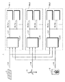
図1は、本開示の第1の実施形態におけるシステムの構成の一例を示す。システム1に対して、例えば、複数の発電装置からの出力が供給される。発電装置として、太陽光発電装置と、風力発電装置と、バイオマス発電装置が例示される。図1では、太陽光パネルにより太陽光発電装置3が模式的に示されている。風車により風力発電装置4が模式的に示されている。タンクおよびタンク内の炎により、バイオマス発電装置5が模式的に示されている。太陽光発電装置3は、公知の太陽光発電装置を適用できる。風力発電装置4およびバイオマス発電装置5についても同様である。
<1. First Embodiment>
"1-1. System configuration"
FIG. 1 illustrates an example of a system configuration according to the first embodiment of the present disclosure. For example, outputs from a plurality of power generators are supplied to the
発電装置は、例えば、光や熱、振動、電波、温度差、イオン濃度差などの、周囲の環境に存在するエネルギーに基づいて発電する。発電装置は、系統電力(グリッド)や、人力によって発電する装置により構成されてもよい。複数の発電装置が同種の発電装置であってもよい。 The power generation device generates power based on energy existing in the surrounding environment such as light, heat, vibration, radio wave, temperature difference, ion concentration difference, and the like. The power generation device may be constituted by a system power (grid) or a device that generates power by human power. The plurality of power generation devices may be the same type of power generation device.
各発電装置によって得られる直流(DC(Direct Current))の電圧が、後段のブロックに供給される。発電装置によって交流(AC(Alternating Current))の電圧が得られる場合は、交流の電圧が直流の電圧に変換されて、後段のブロックに供給される。システム1は、複数のブロックを有する。複数のブロックとして、ブロックBL1、ブロックBL2およびブロックBL3が例示される。個々のブロックを区別する必要がない場合は、ブロックBLと適宜、称する。なお、ブロックとは、説明の便宜上の表記であり、特別の意味を有するものではない。ブロックBLの構成等については、後述する。
A direct current (DC) voltage obtained by each power generator is supplied to the subsequent block. When an AC (Alternating Current) voltage is obtained by the power generation device, the AC voltage is converted into a DC voltage and supplied to the subsequent block. The
ブロックBLは、各発電装置に対して並列に接続される。太陽光発電装置3から供給される直流の電圧V3が、ブロックBL1、ブロックBL2およびブロックBL3に供給される。風力発電装置4から供給される直流の電圧V4が、ブロックBL1、ブロックBL2およびブロックBL3に供給される。バイオマス発電装置5から供給される直流の電圧V5が、ブロックBL1、ブロックBL2およびブロックBL3に供給される。電圧V3、電圧V4および電圧V5のそれぞれが、第1の電圧の一例とされる。
The block BL is connected in parallel to each power generator. A DC voltage V3 supplied from the solar
電圧V3、電圧V4および電圧V5の値は、装置の規模等に応じて変動し得るものであるが、ここでは、電圧V3、電圧V4および電圧V5は、75V(ボルト)から100Vの範囲で変動する電圧として説明する。図1では、電圧V3が実線により示され、電圧V4が一点鎖線により示され、電圧V5が二点鎖線により示されている。 The values of the voltage V3, the voltage V4, and the voltage V5 can vary depending on the scale of the device, but the voltage V3, the voltage V4, and the voltage V5 vary in the range of 75V (volt) to 100V here. The voltage will be described as follows. In FIG. 1, the voltage V3 is indicated by a solid line, the voltage V4 is indicated by a one-dot chain line, and the voltage V5 is indicated by a two-dot chain line.
「1−2.ブロックの構成」
ブロックBLの構成の一例について、ブロックBL1を例にして説明する。ブロックBL1は、例えば、一のコントロールユニットと、少なくとも一のバッテリユニットとを含む構成とされる。コントロールユニットが第1の装置の一例とされ、バッテリユニットが第2の装置の一例とされる。
"1-2. Block configuration"
An example of the configuration of the block BL will be described using the block BL1 as an example. The block BL1 includes, for example, one control unit and at least one battery unit. The control unit is an example of the first device, and the battery unit is an example of the second device.
コントロールユニットCU1に対して、例えば、バッテリユニットBU1a、バッテリユニットBU1bおよびバッテリユニットBU1cが接続される。個々のバッテリユニットを区別する必要がない場合は、バッテリユニットBU1と適宜、称する。図1では、バッテリユニットBU1aおよびバッテリユニットBU1bが図示されている。 For example, a battery unit BU1a, a battery unit BU1b, and a battery unit BU1c are connected to the control unit CU1. When there is no need to distinguish individual battery units, they are appropriately referred to as battery unit BU1. In FIG. 1, a battery unit BU1a and a battery unit BU1b are shown.
コントロールユニットCU1には、例えば、複数のポートが設けられており、各ポートに対してバッテリユニットBU1が着脱自在とされる。すなわち、コントロールユニットCU1に対して接続されるバッテリユニットBU1の個数は、適宜、変更できる。例えば、バッテリユニットBU1a、バッテリユニットBU1b、バッテリユニットBU1cがコントロールユニットCU1に接続された状態で、新たなバッテリユニットをコントロールユニットCU1に対して接続できる。例えば、バッテリユニットBU1a、バッテリユニットBU1bおよびバッテリユニットBU1cがコントロールユニットCU1に接続された状態で、バッテリユニットBU1bをコントロールユニットCU1から離脱することができる。 For example, the control unit CU1 is provided with a plurality of ports, and the battery unit BU1 is detachably attached to each port. That is, the number of battery units BU1 connected to the control unit CU1 can be changed as appropriate. For example, a new battery unit can be connected to the control unit CU1 while the battery unit BU1a, the battery unit BU1b, and the battery unit BU1c are connected to the control unit CU1. For example, the battery unit BU1b can be detached from the control unit CU1 while the battery unit BU1a, the battery unit BU1b, and the battery unit BU1c are connected to the control unit CU1.
バッテリユニットBU1は、ラインL1を介して、コントロールユニットCU1に対して接続される。図2に示すように、ラインL1は、例えば、コントロールユニットCU1からバッテリユニットBU1に対して電力が伝送される電力ラインL10と、バッテリユニットBU1からコントロールユニットCU1に対して電力が伝送される電力ラインL11とを含む。ラインL1は、さらに、コントロールユニットCU1と、各バッテリユニットBU1との間でなされる通信のための信号ラインSL12を含む。 Battery unit BU1 is connected to control unit CU1 via line L1. As shown in FIG. 2, the line L1 includes, for example, a power line L10 that transmits power from the control unit CU1 to the battery unit BU1, and a power line that transmits power from the battery unit BU1 to the control unit CU1. L11. The line L1 further includes a signal line SL12 for communication between the control unit CU1 and each battery unit BU1.
なお、以下の説明では、電力の伝送および通信が、有線によって行われるものとして説明するが、電力の伝送および通信が、無線によって行われてもよい。この場合は、物理的なラインであるラインL1を設ける必要はない。 In the following description, power transmission and communication are described as being performed by wire, but power transmission and communication may be performed wirelessly. In this case, it is not necessary to provide the line L1 which is a physical line.
電力ラインL10を介して、直流の電圧V10が、コントロールユニットCU1からバッテリユニットBU1に供給される。複数のバッテリユニットBU1のうち、充電の指示がなされたバッテリユニットBU1対して、電圧V10に基づく充電が行われる。一のバッテリユニットBU1が充電されてもよく、複数のバッテリユニットBU1が充電されるようにしてもよい。 A DC voltage V10 is supplied from the control unit CU1 to the battery unit BU1 through the power line L10. Among the plurality of battery units BU1, charging based on the voltage V10 is performed on the battery unit BU1 that is instructed to be charged. One battery unit BU1 may be charged, or a plurality of battery units BU1 may be charged.
放電中のバッテリユニットBU1には、充電されない。放電の指示がなされたバッテリユニットBU1から、直流の電圧V11が出力される。電圧V11が、例えば、コントロールユニットCU1を経由して、負荷である外部機器に供給される。コントロールユニットCU1を経由せずに、電圧V11が直接、外部機器に供給されるようにしてもよい。 The battery unit BU1 being discharged is not charged. A direct-current voltage V11 is output from the battery unit BU1 that has been instructed to discharge. The voltage V11 is supplied to an external device that is a load, for example, via the control unit CU1. The voltage V11 may be directly supplied to the external device without going through the control unit CU1.
コントロールユニットCU1と、各バッテリユニットBU1との間でなされる通信は、例えば、SMBus(System Management Bus)やUART(Universal asynchronous Receiver-Transmitter)などの仕様に準じてなされる。信号ラインSL12は、バッテリユニットBU1に対して共通化されたラインであり、信号ラインSL12を制御コマンドが伝送される。例えば、コントロールユニットCU1から、所定のバッテリユニットBU1に対して制御コマンドが送出される。 Communication between the control unit CU1 and each battery unit BU1 is performed according to specifications such as SMBus (System Management Bus) and UART (Universal asynchronous Receiver-Transmitter). The signal line SL12 is a line shared with the battery unit BU1, and a control command is transmitted through the signal line SL12. For example, a control command is sent from the control unit CU1 to a predetermined battery unit BU1.
制御コマンドにより、個々のバッテリユニットBU1を独立して制御できる。バッテリユニットBU1は、自己が接続されたポートのポート番号を識別できる。例えば、制御コマンドのヘッダに、ポート番号を示す識別子が記述される。バッテリユニットBU1は、制御コマンドのヘッダを解析することにより、自己に対する制御コマンドであるか否かを識別できる。 The individual battery units BU1 can be controlled independently by the control command. The battery unit BU1 can identify the port number of the port to which the battery unit BU1 is connected. For example, an identifier indicating a port number is described in the header of the control command. The battery unit BU1 can identify whether it is a control command for itself by analyzing the header of the control command.
さらに、バッテリユニットBU1は、通信により、自己の情報をコントロールユニットCU1に通知できる。バッテリユニットBU1は、例えば、バッテリユニットBU1が有するバッテリの残容量を、通信によりコントロールユニットCU1に通知できる。バッテリユニットBU1からコントロールユニットCU1に対する通知信号のヘッダに、ポート番号を示す識別子が記述される。これにより、コントロールユニットCU1は、どのバッテリユニットBU1からの通知信号であるかを区別できる。 Further, the battery unit BU1 can notify the control unit CU1 of its own information through communication. For example, the battery unit BU1 can notify the control unit CU1 of the remaining battery capacity of the battery unit BU1 by communication. An identifier indicating the port number is described in the header of the notification signal from the battery unit BU1 to the control unit CU1. Thus, the control unit CU1 can distinguish which battery unit BU1 is the notification signal.
複数のバッテリユニットBU1を使用して、例えば、以下のような使用の形態が考えられる。バッテリユニットBU1aに対して、コントロールユニットCU1から充電を指示する制御コマンドが伝送され、バッテリユニットBU1aが充電のための制御を実行する。バッテリユニットBU1bに対して、コントロールユニットCU1から放電を指示する制御コマンドが伝送され、バッテリユニットBU1bが放電のための制御を実行する。バッテリユニットBU1cは、予備の電源として使用される。例えば、バッテリユニットBU1bの残容量が低下した際に、使用するバッテリユニットをバッテリユニットBU1bからバッテリユニットBU1cに切り換える。上述した使用の形態は一例であり、これに限定されることはない。 Using the plurality of battery units BU1, for example, the following modes of use are conceivable. A control command for instructing charging is transmitted from the control unit CU1 to the battery unit BU1a, and the battery unit BU1a executes control for charging. A control command instructing discharging is transmitted from the control unit CU1 to the battery unit BU1b, and the battery unit BU1b executes control for discharging. The battery unit BU1c is used as a spare power source. For example, when the remaining capacity of the battery unit BU1b decreases, the battery unit to be used is switched from the battery unit BU1b to the battery unit BU1c. The form of use mentioned above is an example, and is not limited to this.
ブロックBL2の構成は、例えば、ブロックBL1の構成と同一の構成とされる。ブロックBL2は、コントロールユニットCU2を含む構成とされる。コントロールユニットCU2に対して、ラインL2を介して、例えば、バッテリユニットBU2a、バッテリユニットBU2bおよびバッテリユニットBU2cが接続される。図1では、バッテリユニットBU2aおよびバッテリユニットBU2bが図示されている。 The configuration of the block BL2 is, for example, the same configuration as the configuration of the block BL1. The block BL2 includes a control unit CU2. For example, a battery unit BU2a, a battery unit BU2b, and a battery unit BU2c are connected to the control unit CU2 via a line L2. In FIG. 1, a battery unit BU2a and a battery unit BU2b are shown.
ラインL2は、例えば、コントロールユニットCU2からバッテリユニットBU2に対して電力が伝送される電力ラインL20と、バッテリユニットBU2からコントロールユニットCU2に対して電力が伝送される電力ラインL21とを含む。ラインL2は、さらに、コントロールユニットCU2と、各バッテリユニットBU2との間でなされる通信のための信号ラインSL22を含む。 The line L2 includes, for example, a power line L20 that transmits power from the control unit CU2 to the battery unit BU2, and a power line L21 that transmits power from the battery unit BU2 to the control unit CU2. The line L2 further includes a signal line SL22 for communication between the control unit CU2 and each battery unit BU2.
ブロックBL3の構成は、例えば、ブロックBL1の構成と同一の構成とされる。ブロックBL3は、コントロールユニットCU3を含む構成とされる。コントロールユニットCU3に対して、ラインL3を介して、例えば、バッテリユニットBU3a、バッテリユニットBU3bおよびバッテリユニットBU3cが接続される。図1では、バッテリユニットBU3aおよびバッテリユニットBU3bが図示されている。 The configuration of the block BL3 is, for example, the same configuration as the configuration of the block BL1. The block BL3 includes a control unit CU3. For example, a battery unit BU3a, a battery unit BU3b, and a battery unit BU3c are connected to the control unit CU3 via a line L3. In FIG. 1, a battery unit BU3a and a battery unit BU3b are shown.
ラインL3は、例えば、コントロールユニットCU3からバッテリユニットBU3に対して電力が伝送される電力ラインL30と、バッテリユニットBU3からコントロールユニットCU3に対して電力が伝送される電力ラインL31とを含む。ラインL3は、さらに、コントロールユニットCU3と、各バッテリユニットBU3との間でなされる通信のための信号ラインSL32を含む。 The line L3 includes, for example, a power line L30 in which power is transmitted from the control unit CU3 to the battery unit BU3, and a power line L31 in which power is transmitted from the battery unit BU3 to the control unit CU3. The line L3 further includes a signal line SL32 for communication between the control unit CU3 and each battery unit BU3.
なお、本開示の他の説明と矛盾が生じない範囲において、各ブロックBLの間に構成上の差異があっても構わない。以下の説明において、同一の構成と表記し、重複した説明を省略する場合があるが、これは、本開示の他の説明と矛盾が生じない範囲において、構成上の差異が存在することを排除するものではない。 Note that there may be structural differences between the blocks BL as long as no contradiction arises with other descriptions of the present disclosure. In the following description, the same configuration may be described, and redundant description may be omitted, but this excludes that there is a difference in configuration within a range that does not contradict other descriptions of the present disclosure. Not what you want.
「1−3.コントロールユニットの構成」
図3は、コントロールユニットCU1の構成の概要の一例を示す。コントロールユニットCU1は、変換部100a、変換部100bおよび変換部100cを有する。個々の変換部を区別する必要がない場合は、変換部100と適宜、称する。変換部100aに対して、太陽光発電装置3の出力電圧である電圧V3が供給される。変換部100aは、電圧V3を、電圧V3の大きさに応じた電圧V10に変換する。上述したように、電圧V3は、例えば、75Vから100Vの範囲で変動する電圧である。電圧V10は、例えば、45Vから48Vの範囲で変動する直流の電圧である。
“1-3. Configuration of control unit”
FIG. 3 shows an example of an outline of the configuration of the control unit CU1. The control unit CU1 includes a
変換部100aは、電圧V3が75Vのときは、電圧V10が45Vになるように電圧V3を変換する。変換部100aは、電圧V3が100Vのときは、電圧V10が48Vになるように電圧V3を変換する。電圧V3が75Vから100Vの範囲で変化するのに応じて、変換部100aは、45Vから48Vの範囲で略リニアに変化させるようにして、電圧V3を電圧V10へと変換する。変化率をリニアに変化させることに代えて、各種のフィードバック回路を用いてもよい。フィードバック回路により得られる出力が、変換部100aから出力されるようにしてもよい。
When the voltage V3 is 75V, the
変換部100bおよび変換部100cは、変換部100aと同様に動作する。変換部100bは、電圧V4が75Vのときは、電圧V10が45Vになるように電圧V4を変換する。変換部100aは、電圧V4が100Vのときは、電圧V10が48Vになるように電圧V4を変換する。電圧V4が75Vから100Vの範囲で変化するのに応じて、変換部100aは、45Vから48Vの範囲で略リニアに変化するように電圧V4を電圧V10に変換する。なお、電圧V4が、例えば、200Vから420Vの範囲で変化する場合は、変換部100bは、電圧V4を降圧して、45Vから48Vの範囲の電圧V10を生成する。このように、各変換部100は、入力電圧に応じて、適宜、動作するように構成される。
The
変換部100cは、電圧V5が75Vのときは、電圧V10が45Vになるように電圧V5を変換する。変換部100cは、電圧V5が100Vのときは、電圧V10が48Vになるように電圧V5を変換する。電圧V5が75Vから100Vの範囲で変化するのに応じて、変換部100aは、45Vから48Vの範囲で略リニアに変化させるように電圧V5を電圧V10に変換する。なお、電圧V5が、例えば、10Vから40Vの範囲で変化する場合は、変換部100cは、電圧V5を昇圧して、45Vから48Vの範囲の電圧V10を生成する。このように、変換部100は、入力電圧に応じて適宜、動作するように構成される。
When the voltage V5 is 75V, the
変換部100a、変換部100bおよび変換部100cからそれぞれ電圧V10が出力され、そのうち、一の出力が電力ラインL10を介してバッテリユニットBU1に供給される。例えば、最も大きい電圧V10が、電力ラインL10を介してバッテリユニットBU1に供給される。バッテリユニットBU1における電力の消費量が大きい場合には、複数の変換部からの出力が合成されて、バッテリユニットBU1に供給される場合も有り得る。
Voltage V10 is output from each of
なお、複数の変換部100からの複数の出力のうち、バッテリユニットBU1に供給される出力を選択することができる。詳細は後述するが、変換部100a、変換部100bおよび変換部100cのそれぞれには、例えば、可変抵抗(ボリューム)が設けられる。可変抵抗の値を適切に設定することにより、所定の変換部100から出力される電圧V10をバッテリユニットBU1に供給することができる。
In addition, the output supplied to battery unit BU1 can be selected among the some outputs from the some conversion part 100. FIG. Although details will be described later, for example, a variable resistor (volume) is provided in each of the
図4は、コントロールユニットCU1の構成の一例を示す。コントロールユニットCU1の変換部100aは、電圧V3を電圧V10に変換(降圧)するDC−DCコンバータ101aを有する。電圧V3が、例えば、45Vより小さい場合には、DC−DCコンバータ101aは、昇圧型のDC−DCコンバータとして構成される。DC−DCコンバータ101aの構成としては、公知のものを適用できる。なお、電圧V3として交流の電圧が供給される場合には、DC−DCコンバータ101aの前段に、AC−DCコンバータが設けられてもよい。
FIG. 4 shows an example of the configuration of the control unit CU1. The
DC−DCコンバータ101aの入力段および出力段のそれぞれに、電圧センサ、電子スイッチおよび電流センサが接続される。DC−DCコンバータ101aの出力段には、さらに、可変抵抗が接続される。図4および後述する図7では、電圧センサを矩形のマークで、電子スイッチを丸のマークで、電流センサを斜線が付された丸のマークで、可変抵抗を三角のマークで、それぞれ簡略化して示している。
A voltage sensor, an electronic switch, and a current sensor are connected to the input stage and the output stage of the DC-
DC−DCコンバータ101aの入力段には、電圧センサ101b、電子スイッチ101cおよび電流センサ101dが順次、接続されている。DC−DCコンバータ101aの出力段には、電流センサ101e、電子スイッチ101f、電圧センサ101gおよび可変抵抗101hが順次、接続されている。
A
変換部100bおよび変換部100cの構成は、例えば、変換部100aと同一の構成とされる。変換部100bは、DC−DCコンバータ102aを有する。DC−DCコンバータ102aの入力段には、電圧センサ102b、電子スイッチ102cおよび電流センサ102dが順次、接続されている。DC−DCコンバータ102aの出力段には、電流センサ102e、電子スイッチ102f、電圧センサ102gおよび可変抵抗102hが順次、接続されている。
The configuration of the
変換部100cは、DC−DCコンバータ103aを有する。DC−DCコンバータ103aの入力段には、電圧センサ103b、電子スイッチ103cおよび電流センサ103dが順次、接続されている。DC−DCコンバータ103aの出力段には、電流センサ103e、電子スイッチ103f、電圧センサ103gおよび可変抵抗103hが順次、接続されている。各変換部100の電子スイッチをオフすることにより、変換部100の出力を停止できる。例えば、電子スイッチ101cおよび電子スイッチ101fの少なくとも一方をオフすることにより、変換部100aからの出力を停止できる。
The
電子スイッチに対する制御に代えて、可変抵抗101h、可変抵抗102hおよび可変抵抗103hの抵抗値を調整してもよい。可変抵抗の抵抗値を調整することにより、DC−DCコンバータ101a等の出力に対してリミットをかけることができる。例えば、可変抵抗101hの抵抗値を0または略0にし、可変抵抗102hおよび可変抵抗103hの抵抗値を所定値に設定する。
Instead of controlling the electronic switch, the resistance values of the
DC−DCコンバータ102aの出力電圧が可変抵抗102hにより降下し、DC−DCコンバータ103aの出力電圧が可変抵抗103hにより降下する。最も大きい電圧である、変換部100aから出力される電圧V10が電力ラインL10に供給され、電圧V10がバッテリユニットBU1に供給される。このように、3つの可変抵抗(可変抵抗101h、可変抵抗102hおよび可変抵抗103h)の抵抗値をそれぞれ適切に調整することにより3つの変換部(変換部100a、変換部100bおよび変換部100c)からの出力のうち、一の出力を選択することができる。
The output voltage of the DC-
コントロールユニットCU1は、さらに、CPU(Central Processing Unit)110を有する。CPU110に対して、メモリ111、D/A(Digital to Analog)変換部112、A/D(Analog to Digital)変換部113および温度センサ114が、バス115を介して接続される。バス115は、例えば、I2Cバスにより構成される。
The control unit CU1 further includes a CPU (Central Processing Unit) 110. A
CPU110は、コントロールユニットCU1の各部を制御する。CPU110は、例えば、変換部100の電子スイッチのオン/オフを制御したり、変換部100における電圧センサや電流センサから供給されるセンサ情報に応じた制御を実行する。
The
なお、電圧センサや電流センサを示すマークから延伸する矢印は、センサにより得られるセンサ情報が、A/D変換部113を介してCPU110に供給されることを示している。さらに、電子スイッチや可変抵抗を示すマークに向かう矢印は、電子スイッチや可変抵抗に対する制御がCPU110により行われることを示している。
An arrow extending from a mark indicating a voltage sensor or a current sensor indicates that sensor information obtained by the sensor is supplied to the
CPU110は、さらに、コントロールユニットCU1に対して接続されるバッテリユニットBU1に対する制御を実行する。例えば、CPU110は、所定のバッテリユニットBU1の電源をオンさせる制御コマンドや、所定のバッテリユニットBU1に対して、充電または放電を指示する制御コマンドを生成する。そして、CPU110は、生成した制御コマンドを信号ラインSL12に送出する。さらに、CPU10は、各バッテリユニットBU1から送信される情報(例えば、バッテリユニットBU1のバッテリの残容量)を取得し、取得した情報に応じた制御を行う。
メモリ111は、CPU110が実行するプログラムが格納されるROM(Read Only Memory)、CPU110が処理を実行する際のワークメモリとして使用されるRAM(Random Access Memory)、各種のデータ(例えば、後述するスケジュールテーブル)が記憶されるEEPROM(Electrically Erasable and Programmable Read Only Memory)等の不揮発性メモリなどのメモリを総称したものである。
The
D/A変換部112は、デジタルデータをアナログデータに変換する。A/D変換部113は、アナログデータをデジタルデータに変換する。A/D変換部113に、例えば、電圧センサや電流センサから、アナログデータのセンサ情報が供給される。A/D変換部113は、アナログデータのセンサ情報をデジタルデータのセンサ情報に変換する。デジタルデータのセンサ情報が、CPU110に供給される。
The D /
温度センサ114は、環境温度を測定する。例えば、コントロールユニットCU1の内部の温度や、コントロールユニットCU1の周囲の温度を測定する。温度センサ114によって得られる温度情報がA/D変換部113によりデジタルデータに変換された後に、CPU110に供給される。
The
コントロールユニットCU1と他の機器との間で、通信が行われるようにしてもよい。例えば、CPU110が通信機能を有する構成とし、CPU110と他の機器118との間で通信が行われる。他の機器118として、パーソナルコンピュータ(PC)や、タブレット型のコンピュータや、スマートフォンなどの機器が例示される。
Communication may be performed between the control unit CU1 and another device. For example, the
通信は、インターネットを介した通信でもよく、近距離の無線の通信でもよい。近距離無線の方式による通信としては、例えば、赤外線を用いた通信や、「Zigbee(登録商標)」規格による通信、「Bluetooth(登録商標)」規格による通信、ネットワーク形成が容易な「Wi Fi(登録商標)」による通信などを利用することができるが、これらに限定されるものではない。 The communication may be communication via the Internet or short-range wireless communication. As communication by the short-range wireless method, for example, communication using infrared rays, communication based on the “Zigbee (registered trademark)” standard, communication based on the “Bluetooth (registered trademark)” standard, “Wi Fi ( (Registered trademark) "can be used, but is not limited thereto.
図5は、変換部100aの具体的な構成の一例を示す。図5に示すように、変換部110aは、DC−DCコンバータ101aと、後述するフィードフォワード制御系とを備えている。図5では、電圧センサ101b、電子スイッチ101c、電流センサ101d、電流センサ101e、電子スイッチ101f、電圧センサ101gおよび可変抵抗101hの図示を省略している。
FIG. 5 shows an example of a specific configuration of the
DC−DCコンバータ101aは、例えば、スイッチング素子などを含む一次側回路121と、トランス122と、整流素子などを含む二次側回路123とから構成される。図5に示すDC−DCコンバータ101aは、例えば、電流共振型のコンバータ(LLC共振コンバータ)である。
The DC-
フィードフォワード制御系は、オペアンプ124、トランジスタ125、抵抗Rc1、抵抗Rc2および抵抗Rc3を含み、フィードフォワード制御系の出力は、例えば、DC−DCコンバータ101aの一次側回路121のドライバに備えられた制御用端子に入力される。DC−DCコンバータ101aは、制御用端子に対する入力電圧が一定となるように、変換部100aからの出力電圧を調整する。
The feedforward control system includes an
変換部100aがフィードフォワード制御系を備えることにより、変換部100aからの出力電圧である電圧V10の値が、あらかじめ設定された範囲内の電圧値となるように調整される。したがって、変換部100aを備えるコントロールユニットCU1は、例えば、太陽光発電装置3からの入力電圧(電圧V3)の変化に応じて出力電圧(電圧V10)を変化させる電圧変換装置の機能を有している。
When the
図5に示すように、変換部100aからは、一次側回路121、トランス122、二次側回路123を介して出力電圧が取り出される。コントロールユニットCU1からの出力は、電力ラインL10により、バッテリユニットBU1に送出される。なお、電圧V3が交流の電圧である場合は、一次側回路121の前段にAC−DCコンバータが接続される。AC−DCコンバータは、例えば、力率補正(Power Factor Correction)回路である。
As illustrated in FIG. 5, the output voltage is extracted from the
以下、変換部100aが有するフィードフォワード制御系について説明する。
Hereinafter, the feedforward control system which the
オペアンプ124の非反転入力端子に対しては、変換部100aへの入力電圧(電圧V3)をkc倍(kc:数十〜百分の一程度)した電圧が入力される。一方、オペアンプ124の反転入力端子c1に対しては、あらかじめ定められた一定の電圧Vt0をkc倍した電圧が入力されている。オペアンプ124の反転入力端子c1に対する入力電圧(kc×Vt0)は、例えば、D/A変換部112から印加される。電圧Vt0の値は、例えば、D/A変換部112の内蔵メモリに保持され、必要に応じて、電圧Vt0の値を変更することが可能とされている。電圧Vt0の値が、バス115を介してCPU110に接続されたメモリ111に保持され、これをD/A変換部112に転送するようにしてもよい。電圧Vt0の値は、固定値でもよい。
A voltage obtained by multiplying the input voltage (voltage V3) to the
オペアンプ124の出力端子はトランジスタ125のベースに接続されており、トランジスタ125により、オペアンプ124の非反転入力端子に対する入力電圧と反転入力端子に対する入力電圧との差に応じた電圧−電流変換が行われる。
The output terminal of the
トランジスタ125のエミッタに接続された抵抗Rc2の抵抗値は、抵抗Rc1と並列に接続される抵抗Rc2の抵抗値に対して大きな値を持つように設定されている。
The resistance value of the resistor Rc2 connected to the emitter of the
例えば、変換部100aに対する入力電圧が、あらかじめ定められた一定の電圧Vt0よりも十分に高い電圧であったとする。このとき、トランジスタ125はオンであり、抵抗Rc1および抵抗Rc2の合成抵抗の値が抵抗Rc1の抵抗値より小となるため、図5に示すf点の電位はグラウンド電位に近づく。
For example, the input voltage to the
すると、フォトカプラ126を介して接続された、一次側回路121のドライバに備えられた制御用端子に対する入力電圧が低下する。制御用端子に対する入力電圧の低下を検出したDC−DCコンバータ101aは、制御用端子に対する入力電圧が一定となるように、変換部100aからの出力電圧を引き上げる。
Then, the input voltage to the control terminal provided in the driver of the
反対に、例えば、コントロールユニットCU1に接続される太陽電池の端子電圧が低下し、変換部100aに対する入力電圧が、あらかじめ定められた一定の電圧Vt0に近づいたとする。
Conversely, for example, reduces the terminal voltage of the solar cell to be connected to the control unit CU1, the input voltage to the
変換部100aに対する入力電圧が下がってくると、トランジスタ125の状態が、オンからオフの状態に近づく。トランジスタ125の状態がオンからオフの状態に近づくに伴い、抵抗Rc1および抵抗Rc2には電流が流れにくくなり、図5に示すf点の電位が上昇する。
When the input voltage to the
すると、一次側回路121のドライバに備えられた制御用端子に対する入力電圧が一定に保たれなくなるため、DC−DCコンバータ101aは、制御用端子に対する入力電圧が一定となるように、変換部100aからの出力電圧を引き下げる。
Then, since the input voltage to the control terminal provided in the driver of the
すなわち、変換部100aは、入力電圧があらかじめ定められた一定の電圧Vt0よりも十分に高い電圧である場合には、出力電圧を引き上げる。また、変換部100aは、太陽電池の端子電圧が低下して、入力電圧があらかじめ定められた一定の電圧Vt0に近づくと、出力電圧を引き下げる。このように、変換部100aを備えるコントロールユニットCU1は、入力電圧の大きさに応じて出力電圧を動的に変化させる。
That is, the
さらに、以下に説明するように、変換部100aは、コントロールユニットCU1の出力側で必要とされる電圧の変化に対しても出力電圧を動的に変化させる。
Furthermore, as will be described below, the
例えば、太陽光発電装置3の発電中に、コントロールユニットCU1に対して電気的に接続され、充電されるバッテリユニットBU1の数が増加したとする。すなわち、太陽光発電装置3からみた負荷が増加したとする。
For example, it is assumed that the number of battery units BU1 that are electrically connected and charged to the control unit CU1 during power generation by the solar
この場合、コントロールユニットCU1に対して新たにバッテリユニットBU1が電気的に接続されることにより、コントロールユニットCU1に接続されている太陽電池の端子電圧が下がることになる。すると、変換部100aに対する入力電圧が低下するに伴い、トランジスタ125の状態が、オンからオフの状態に近づくこととなり、変換部100aからの出力電圧を引き下げられる。
In this case, when the battery unit BU1 is newly electrically connected to the control unit CU1, the terminal voltage of the solar cell connected to the control unit CU1 is lowered. Then, as the input voltage to the
一方、例えば、太陽光発電装置3の発電中に、コントロールユニットCU1に対して電気的に接続され、充電されるバッテリユニットBU1の数が減少したとすると、太陽光発電装置3が有する太陽電池からみた負荷が減少するため、コントロールユニットCU1に接続される太陽電池の端子電圧が上昇する。変換部100aに対する入力電圧が、あらかじめ定められた一定の電圧Vt0よりも十分に高い電圧になると、一次側回路121のドライバに備えられた制御用端子に対する入力電圧が低下し、変換部100aからの出力電圧が引き上げられる。
On the other hand, for example, if the number of battery units BU1 that are electrically connected and charged to the control unit CU1 during power generation by the solar
なお、抵抗Rc1、抵抗Rc2および抵抗Rc3の抵抗値は、変換部100aからの出力電圧の値があらかじめ設定された範囲内の電圧値となるように適宜選択される。すなわち、抵抗Rc1および抵抗Rc2の抵抗値により、変換部100aからの出力電圧の上限がきめられる。トランジスタ125は、変換部100aに対する入力電圧が所定の値を超えているときに、変換部100aからの出力電圧の値が、あらかじめ設定された上限の電圧値を超えないようにするために配置されている。
The resistance values of the resistors Rc1, Rc2, and Rc3 are appropriately selected so that the value of the output voltage from the
一方、変換部100aからの出力電圧の下限は、後述するように、バッテリユニットBU1における充電制御部におけるフィードフォワード制御系のオペアンプの反転入力端子に対する入力電圧によってきめられる。
On the other hand, the lower limit of the output voltage from
変換部100bおよび変換部100cの構成は、例えば、変換部100aの構成と同一とされる。変換部100bおよび変換部100cは、例えば、変換部100aと同様に動作する。
The configurations of the
コントロールユニットCU1、コントロールユニットCU2およびコントロールユニットCU3の電源は、それぞれ独立してオン/オフすることができる。図6は、コントロールユニットCU1の、主に電源系統に関する構成の一例を示す。 The power sources of the control unit CU1, the control unit CU2, and the control unit CU3 can be independently turned on / off. FIG. 6 shows an example of the configuration of the control unit CU1 mainly related to the power supply system.
変換部100aの出力段には、逆流防止用のダイオード130aが接続される。変換部100bの出力段には、逆流防止用のダイオード130bが接続される。変換部100cの出力段には、逆流防止用のダイオード130cが接続される。ダイオード130a、ダイオード130bおよびダイオード130cにより、変換部100a、変換部100bおよび変換部100cがOR接続される。
A
変換部100a、変換部100bおよび変換部100cからの出力が合成されてバッテリユニットBU1に供給される。実際には、変換部100a、変換部100bおよび変換部100cからの出力のうち、最も電圧が高い一の出力がバッテリユニットBU1に供給される。但し、バッテリユニットBU1の電力の消費量に応じて、複数の変換部100からの出力が供給される状況にもなり得る。
Outputs from the
コントロールユニットCU1には、ユーザによって操作可能なメインスイッチSW1が設けられている。メインスイッチSW1がオンされることでCPU110に電力が供給され、コントロールユニットCU1が起動する。メインスイッチSW1に対して、リモートコントロール装置によるオン/オフの切替操作などの遠隔操作が可能とされてもよい。
The control unit CU1 is provided with a main switch SW1 that can be operated by the user. When the main switch SW1 is turned on, power is supplied to the
CPU110に、例えば、コントロールユニットCU1に内蔵されるバッテリ133から電力が供給される。バッテリ133は、例えば、リチウムイオン二次電池である。バッテリ133からの供給される直流の電圧がDC−DCコンバータ134によって、CPU110に対応する電圧に変換される。変換された電圧が、電源電圧としてCPU110に供給される。コントロールユニットCU1の起動時には、バッテリ133が使用される。バッテリ133に対する制御(例えば、充放電制御)は、例えば、CPU110によって行われる。
For example, power is supplied to the
バッテリ133は、例えば、バッテリユニットBU1から供給される電圧に基づいて充電することができる。変換部100aや変換部100bなどから供給される電圧に基づいて、バッテリ133が充電されてもよい。
The
例えば、バッテリユニットBU1aから供給される電圧V11が充電制御部135に供給される。充電制御部135は、電圧V11を適切な電圧へと変換し、変換した電圧に基づいて、バッテリ133を充電する。充電制御部135による充電は、例えば、CVCC(Constant Voltage Constant Current)による方式に基づいて実行される。
For example, the voltage V11 supplied from the battery unit BU1a is supplied to the
なお、バッテリユニットBU1から供給される電圧V12あるいは変換部100aや変換部100bなどから供給される電圧に基づいて、CPU110が動作するようにしてもよい。バッテリユニットBU1から供給される電圧V11がDC−DCコンバータ136によって所定のレベルの電圧に変換される。変換された電圧が、電源電圧としてCPU110に供給され、CPU110が動作する。
Note that the
コントロールユニットCU1が起動した後に、CPU110は、変換部100a、変換部100bおよび変換部100cのうち、少なくとも一の変換部をオンする、電圧V3、電圧V4および電圧V5のうち少なくとも一の電圧が、コントロールユニットCU1の対応する変換部に入力され、その変換部から電圧V10が出力される。電圧V10が、電力ラインL10を介してバッテリユニットBU1に供給される。
After the control unit CU1 is activated, the
CPU110は、信号ラインSLを使用してバッテリユニットBU1と通信を行う。この通信によって、CPU110は、バッテリユニットBU1に対して起動および放電を指示する制御コマンドを出力する。CPU110は、スイッチSW2をオンする。スイッチSW2は、例えば、FET(Field Effect Transistor)から構成される。IGBT(Insulated Gate Bipolar Transistor)によって構成されてもよい。スイッチSW2がオンされることで、所定のバッテリユニットBU1からコントロールユニットCU1に電圧V11が供給される。
バッテリユニットBU1から供給される電圧V11を外部機器に供給するときは、CPU110は、スイッチSW3をオンする。スイッチSW3がオンされることで、電圧V11に基づく電圧V12が、電力ラインL12を介して外部機器に供給される。電圧V12は、電圧V11そのものでもよく、外部機器に対応するように電圧V11に変換処理が施されたものでもよい。電力ラインL12には、負荷である種々の外部機器が接続される。なお、電圧V12に基づく電力が放電中のバッテリユニットBU1と異なるバッテリユニットBU1に供給され、供給先のバッテリユニットBU1が充電されるようにしてもよい。
When supplying the voltage V11 supplied from the battery unit BU1 to the external device, the
スイッチSW2の出力側(カソード側)には、逆流防止用のダイオード130dが接続される。ダイオード130dを接続することにより、太陽光発電装置3や風力発電装置4などから供給される不安定な電力が、負荷である外部機器に直接、供給されることを防止できる。外部機器には、バッテリユニットBU1から供給される安定した電力を供給できる。もちろん、安全のために、バッテリユニットBU1の最終段にダイオードを設けてもよい。
A
以上、ブロックBL1におけるコントロールユニットCU1の構成の一例について説明した。なお、他のブロックBLにおけるコントロールユニット(例えば、コントロールユニットCU2およびコントロールユニットCU3)の構成は、例えば、コントロールユニットCU1と同一の構成とされ、コントロールユニットCU1と同様に動作する。 The example of the configuration of the control unit CU1 in the block BL1 has been described above. The configuration of the control units (for example, the control unit CU2 and the control unit CU3) in the other blocks BL is the same as that of the control unit CU1, for example, and operates in the same manner as the control unit CU1.
なお、可変抵抗の抵抗値を適宜、調整することにより、変換部100aからの出力電圧、変換部100bからの出力電圧および変換部100cからの出力電圧のうち、どの出力電圧を優先するかを決定する例を説明したが、他の方法によって優先する出力電圧を決定してもよい。例えば、各変換部100における抵抗Rc1、抵抗Rc2および抵抗Rc3の抵抗値を調整することにより、優先して供給する出力電圧を決定してもよい。
Note that, by appropriately adjusting the resistance value of the variable resistor, it is determined which output voltage has priority among the output voltage from the
変換部の出力電圧を変更してもよい。例えば、太陽光発電装置3から供給される電力を優先して使用するものとする。この場合に、変換部100aの出力電圧を45Vから48Vの範囲から、やや高い値の範囲に変更する。この変更は、上述したように、抵抗Rc1、抵抗Rc2および抵抗Rc3の抵抗値を適切に設定することにより可能となる。これにより、変換部100aの出力を他の変換部(変換部100bおよび変換部100c)に優先して、バッテリユニットBUに供給することができる。
The output voltage of the conversion unit may be changed. For example, power supplied from the solar
出力電圧の範囲として、以下の範囲が例示される。
(1)上限(48V)および下限(45V)を共に高くする(例えば、45.5V〜48.5Vの範囲)。
(2)下限のみを高くする(例えば、45.5V〜48Vの範囲)。
(3)上限のみを高くする(例えば、45V〜48.5Vの範囲)。
Examples of the output voltage range include the following ranges.
(1) The upper limit (48V) and the lower limit (45V) are both increased (for example, a range of 45.5V to 48.5V).
(2) Only the lower limit is increased (for example, a range of 45.5V to 48V).
(3) Only the upper limit is increased (for example, a range of 45V to 48.5V).
(1)に例示する設定では、変換部100aの出力を常に優先することができる。(2)に例示する設定では、例えば、電圧V3の値が小さい場合(例えば、75Vから80V付近)に、変換部100aの出力を優先できる。電圧V3の値が大きい場合は、他の変換部(変換部100bおよび変換部100c)の出力と同等に扱われる。(3)に例示する設定では、例えば、電圧V3の値が大きい場合(例えば、100V付近)に、変換部100aの出力を優先できる。電圧V3の値が小さい場合(例えば、75Vから80V付近)に、他の変換部(変換部100bおよび変換部100c)の出力と同等に扱われる。以上のようにして、所定の変換部からの出力電圧を優先してバッテリユニットに供給することができる。同様にして、変換部100bや変換部100cの出力を優先してバッテリユニットBUに供給することができる。
In the setting exemplified in (1), the output of the
「1−4.バッテリユニットの構成」
次に、コントロールユニットCUに接続されるバッテリユニットBUについて説明する。以下の説明では、コントロールユニットCU1に接続されるバッテリユニットBU1aを例にして説明する。
“1-4. Configuration of Battery Unit”
Next, the battery unit BU connected to the control unit CU will be described. In the following description, the battery unit BU1a connected to the control unit CU1 will be described as an example.
図7は、バッテリユニットBU1aの構成の一例を示す。バッテリユニットBU1aは、充電制御部140と、放電制御部141と、バッテリBaとを含む構成とされる。コントロールユニットCU1から充電制御部140に対して、電圧V10が供給される。バッテリユニットBU1aからの出力である電圧V11が、放電制御部141を介してコントロールユニットCU1に供給される。バッテリユニットBU1aに電力ラインL11とは異なる電力ラインL14が設けられる。電力ラインL14を介して、放電制御部141から外部機器に対して、直接、電圧V11が供給される。電力ラインL14はなくてもよい。
FIG. 7 shows an example of the configuration of the battery unit BU1a. The battery unit BU1a includes a
蓄電部の一例であるバッテリBaは、例えば、リチウムイオン二次電池等の充電可能なバッテリである。充電制御部140および放電制御部141は、バッテリBaの種類に対応した構成とされる。
The battery Ba, which is an example of a power storage unit, is a rechargeable battery such as a lithium ion secondary battery. The
充電制御部140は、DC−DCコンバータ142aを備える。充電制御部140に入力される電圧V10が、DC−DCコンバータ142aによって所定の電圧に変換される。DC−DCコンバータ142aから出力される電圧がバッテリBaに供給され、バッテリBaが充電される。所定の電圧の値は、バッテリBaの種類等に応じて異なる。DC−DCコンバータ142aの入力段には、電圧センサ142bと、電子スイッチ142cと、電流センサ142dとが接続される。DC−DCコンバータ142aの出力段には、電流センサ142eと、電子スイッチ142fと、電圧センサ142gとが接続される。
The charging
放電制御部141は、DC−DCコンバータ143aを備える。DC−DCコンバータ143aは、バッテリBaから放電制御部141に供給される直流の電圧に基づいて、電圧V11を生成する。電圧V11が放電制御部141から出力される。DC−DCコンバータ143aの入力段には、電圧センサ143bと、電子スイッチ143cと、電流センサ143dとが接続される。DC−DCコンバータ143aの出力段には、電流センサ143eと、電子スイッチ143fと、電圧センサ143gとが接続される。
The
バッテリユニットBU1aは、CPU145を有する。CPU145は、バッテリユニットBU1aの各部を制御する。例えば、充電制御部140や放電制御部141における電子スイッチのオン/オフを制御する。過充電防止機能や過電流防止機能などの安全を確保する処理をCPU145が行うようにしてもよい。CPU145は、信号ラインSLを介して、コントロールユニットCU1のCPU110と通信を行い、制御コマンドやデータがやり取りされる。
The battery unit BU1a has a
CPU145に対して、バス149を介して、メモリ146と、A/D変換部147と、温度センサ148とが接続される。バス149は、例えば、I2Cバスにより構成される。
A
メモリ146は、CPU145が実行するプログラムが格納されるROM、CPU145が処理を実行する際のワークメモリとして使用されるRAM、各種のデータが記憶されるEEPROM等の不揮発性メモリなどのメモリを総称したものである。
The
A/D変換部147に、例えば、電圧センサや電流センサから、アナログデータのセンサ情報が供給される。A/D変換部147は、アナログデータのセンサ情報をデジタルデータのセンサ情報に変換する。デジタルデータのセンサ情報が、CPU145に供給される。
For example, sensor information of analog data is supplied to the A /
温度センサ148は、環境温度を測定する。例えば、バッテリユニットBU1aの内部の温度や、バッテリユニットBU1aの周囲の温度を測定する。温度センサ148によって得られる温度情報がA/D変換部147によりデジタルデータに変換された後に、CPU145に供給される。
The
図8は、バッテリユニットBU1aにおける充電制御部140の構成の一例を示す。図8に示すように、充電制御部140は、DC−DCコンバータ142aと、後述するフィードフォワード制御系およびフィードバック制御系とを備えている。なお、図8では、電圧センサ142b、電子スイッチ142c、電流センサ142d、電流センサ142e、電子スイッチ142fおよび電圧センサ142gの図示を省略している。
FIG. 8 shows an example of the configuration of the charging
DC−DCコンバータ142aは、例えば、トランジスタ151、コイル152、制御用IC(Integrated Circuit)153などから構成される。トランジスタ151は、制御用IC153により制御される。
The DC-
フィードフォワード制御系は、オペアンプ155、トランジスタ156、抵抗Rb1、抵抗Rb2および抵抗Rb3を含む。フィードフォワード制御系の出力は、例えば、DC−DCコンバータ142aの制御用IC153に備えられる制御用端子に入力される。DC−DCコンバータ142a中の制御用IC153は、制御用端子に対する入力電圧が一定となるように、充電制御部140からの出力電圧を調整する。
The feedforward control system includes an
すなわち、充電制御部140に備えられたフィードフォワード制御系は、変換部100aに備えられたフィードフォワード制御系と同様に作用する。
That is, the feedforward control system provided in the charging
充電制御部140がフィードフォワード制御系を備えることにより、充電制御部140からの出力電圧の値が、あらかじめ設定された範囲内の電圧値となるように調整される。充電制御部140からの出力電圧の値が、あらかじめ設定された範囲内の電圧値に調整されることにより、コントロールユニットCU1に電気的に接続された各バッテリBに対する充電電流が、変換部100aからの入力電圧(電圧V10)の変化に応じて調整される。したがって、充電制御部140を備えるバッテリユニットBU1aは、バッテリBaに対する充電レートを変化させる充電装置としての機能を有している。
When the charging
コントロールユニットCU1に電気的に接続された各バッテリBに対する充電レートが変化させられることにより、各バッテリユニットBU1の充電制御部140に対する入力電圧の値(変換部100a、変換部100bおよび変換部100cの少なくとも一つからの出力電圧の値といってもよい。)が、あらかじめ設定された範囲内の電圧値となるように調整される。
By changing the charging rate for each battery B electrically connected to the control unit CU1, the value of the input voltage to the charging
図8に示すように、充電制御部140からは、DC−DCコンバータ142a、電流センサ154、フィルタ159を介して出力電圧が取り出される。出力電圧がバッテリBaに供給される。
As shown in FIG. 8, the output voltage is taken out from the charging
後述するように、充電制御部140からの出力電圧の値は、充電制御部140に接続されるバッテリの種類に応じて、あらかじめ設定された範囲内の電圧値となるように調整されている。充電制御部140からの出力電圧の範囲は、抵抗Rb1、抵抗Rb2および抵抗Rb3の抵抗値が適宜選択されることにより調整される。
As will be described later, the value of the output voltage from the charging
このように、充電制御部140からの出力電圧の範囲が、充電制御部140に接続されるバッテリBの種類に応じて個別にきめられるため、バッテリユニットBU1に備えられるバッテリBの種類は特に限定されない。充電制御部140内の抵抗Rb1、抵抗Rb2および抵抗Rb3の抵抗値を、接続されるバッテリBの種類に応じて適宜選択すればよいからである。
Thus, since the range of the output voltage from the
なお、図8ではフィードフォワード制御系の出力が制御用IC153の制御用端子に入力される構成を例示したが、バッテリユニットBU1のCPU145が、制御用IC153の制御用端子に入力を与えるようにしてもよい。例えば、バッテリユニットBU1のCPU145が、信号ラインSLを介してバッテリユニットBU1に対する入力電圧に関する情報をコントロールユニットCU1のCPU110から取得するようにしてもよい。コントロールユニットCU1のCPU110は、電圧センサ101g、電圧センサ102g、電圧センサ103gなどの測定結果から、バッテリユニットBU1に対する入力電圧に関する情報を取得することが可能である。
8 illustrates the configuration in which the output of the feedforward control system is input to the control terminal of the
以下、充電制御部140に備えられたフィードフォワード制御系について説明する。
Hereinafter, the feedforward control system provided in the charging
オペアンプ155の非反転入力端子に対する入力は、充電制御部140への入力電圧(電圧V10)をkb倍(kb:数十〜百分の一程度)した電圧とされる。一方、オペアンプ155の反転入力端子b1に対する入力は、変換部100a、変換部100bおよび変換部100cの出力電圧の下限として設定しようとする電圧Vbをkb倍した電圧である。オペアンプ155の反転入力端子b1に対する入力電圧(kb×Vb)は、例えば、CPU145から印加される。
The input to the non-inverting input terminal of the
したがって、充電制御部140に備えられたフィードフォワード制御系は、充電制御部140に対する入力電圧が、あらかじめ定められた一定の電圧Vbよりも十分に高い電圧である場合に、充電制御部140からの出力電圧を引き上げる。また、充電制御部140に対する入力電圧が、あらかじめ定められた一定の電圧Vbに近づくと、フィードフォワード制御系は、充電制御部140からの出力電圧を引き下げる。
Therefore, the feedforward control system provided in the charging
トランジスタ156は、図5に示すトランジスタ125と同様に、充電制御部140に対する入力電圧が所定の値を超えているときに、充電制御部140からの出力電圧の値が、あらかじめ設定された上限を超えないようにするために配置されている。なお、充電制御部140からの出力電圧の値の範囲は、抵抗Rb1、抵抗Rb2および抵抗Rb3の抵抗値の組み合わせによってきまる。そのため、抵抗Rb1、抵抗Rb2および抵抗Rb3の抵抗値は、充電制御部140に接続されるバッテリBの種類に応じて調整される。
Similarly to the
上述したように、充電制御部140は、さらに、フィードバック制御系を備える。フィードバック制御系は、例えば、電流センサ154、オペアンプ157およびトランジスタ158などから構成される。
As described above, the charging
バッテリBaに供給される電流量があらかじめ設定された規定値を超えると、フィードバック制御系により、充電制御部140からの出力電圧が引き下げられ、バッテリBaに供給される電流量が制限される。フィードバック制御系による、バッテリBaに供給される電流量の制限の程度は、充電制御部140に接続されるバッテリBaの定格にあわせてきめられる。
When the amount of current supplied to the battery Ba exceeds a preset specified value, the output voltage from the charging
フィードフォワード制御系またはフィードバック制御系により、充電制御部140からの出力電圧が引き下げられると、バッテリBaに供給される電流量が制限されることになる。バッテリBaに供給される電流量が制限されると、結果として、充電制御部140に接続されたバッテリBaに対する充電が減速される。
When the output voltage from the charging
図9は、バッテリユニットBU1aの、主に電源系統に関する構成の一例を示す。バッテリユニットBU1aには、メインスイッチは設けられていない。バッテリBaとCPU145との間には、スイッチSW5およびDC−DCコンバータ160が接続される。バッテリBaと放電制御部141との間には、スイッチSW6が接続される。充電制御部140の入力段には、スイッチSW7が接続される。放電制御部141の出力段には、スイッチSW8が接続される。それぞれのスイッチSWは、例えば、FETにより構成される。
FIG. 9 shows an example of the configuration of the battery unit BU1a mainly related to the power supply system. The battery unit BU1a is not provided with a main switch. A switch SW5 and a DC-
バッテリユニットBU1aは、例えば、コントロールユニットCU1からの制御コマンドによって起動される。コントロールユニットCU1から、所定の信号ラインを介して、例えば、ハイレベルの信号が常に供給されている。このため、バッテリユニットBU1aのポートを所定の信号ラインに接続するだけでハイレベルの信号がスイッチSW5に供給され、スイッチSW5がオンされる。スイッチSW5がオンすることで、バッテリユニットBU1aが起動する。スイッチSW5がオンすることで、バッテリBaからの電圧がDC−DCコンバータ160に供給される。バッテリBaからの電圧に基づく電源電圧が、DC−DCコンバータ160により生成される。電源電圧がCPU145に供給され、CPU145が動作する。
The battery unit BU1a is activated by a control command from the control unit CU1, for example. For example, a high level signal is always supplied from the control unit CU1 via a predetermined signal line. Therefore, only by connecting the port of the battery unit BU1a to a predetermined signal line, a high level signal is supplied to the switch SW5, and the switch SW5 is turned on. When the switch SW5 is turned on, the battery unit BU1a is activated. When the switch SW5 is turned on, the voltage from the battery Ba is supplied to the DC-
CPU145は、コントロールユニットCU1の制御コマンドに応じた処理を実行する。コントロールユニットCU1からCPU145に対して、例えば、充電を指示する制御コマンドが供給される。充電を指示するコマンドに応じて、CPU145は、スイッチSW6およびスイッチSW8をオフした後にスイッチSW7をオンする。スイッチSW7がオンされることで、コントロールユニットCU1から供給される電圧V10が、充電制御部140に供給される。充電制御部140によって電圧V10が所定値の電圧に変換され、変換された電圧によりバッテリBaが充電される。なお、バッテリBaに対する充電方式は、バッテリBaの種類に応じて適宜変更することができる。
The
コントロールユニットCU1からCPU145に対して、例えば、放電を指示する制御コマンドが供給される。放電を指示する制御コマンドに応じて、CPU145は、スイッチSW7をオフし、スイッチSW6およびスイッチSW8をオンする。例えば、スイッチSW6をオンしてから、一定時間後にスイッチSW8をオンする。スイッチSW6がオンされることで、バッテリBaから電圧が放電制御部141に供給される。放電制御部141によって、バッテリBaから供給される電圧が電圧V11に変換される。変換された電圧V11が、スイッチSW8を介してコントロールユニットCU1に供給される。なお、他のバッテリユニットBU1からの出力と衝突しないようにするため、スイッチSW8の後段にダイオードを追加してもよい。
For example, a control command for instructing discharge is supplied from the control unit CU1 to the
なお、CPU145の制御によって、放電制御部141のオン/オフを切り換えることができる。CPU145から放電制御部141に向かうON/OFF信号線を介して、オン/オフを切り替える制御コマンドが放電制御部141に供給される。制御コマンドに応じて、放電制御部141の電子スイッチ143cおよび電子スイッチ143fの少なくとも一方のオン/オフが切り替えられる。
The
以上、バッテリユニットBUの構成の一例について、バッテリユニットBU1aを例について説明した。なお、バッテリユニットBU1bおよびバッテリユニットBU1cは、例えば、バッテリユニットBU1aと同様の構成を有し、同様の動作をする。各バッテリユニットBUの間に構成上の差異があっても構わない。例えば、バッテリユニットBU1bが有するバッテリBが、リチウムイオン電池以外の二次電池でもよい。 The example of the battery unit BU1a has been described above as an example of the configuration of the battery unit BU. The battery unit BU1b and the battery unit BU1c have, for example, the same configuration as the battery unit BU1a and perform the same operation. There may be a structural difference between the battery units BU. For example, the battery B included in the battery unit BU1b may be a secondary battery other than a lithium ion battery.
他のブロックのバッテリユニット(例えば、バッテリユニットBU2aやバッテリユニットBU3a)は、例えば、バッテリユニットBU1aと同様の構成を有し、同様の動作をする。 The battery units (for example, the battery unit BU2a and the battery unit BU3a) in other blocks have the same configuration as the battery unit BU1a and perform the same operation.
「1−5.動作の概要」
次に、ブロックBL1における動作の一例について説明する。ブロックBL2やブロックBL3は、例えば、ブロックBL1と同様に動作する。ブロックBL2やブロックBL3の動作に関する説明は、適宜、省略する。
"1-5. Outline of operation"
Next, an example of the operation in the block BL1 will be described. For example, the block BL2 and the block BL3 operate in the same manner as the block BL1. A description of the operation of the block BL2 and the block BL3 will be omitted as appropriate.
ブロックBL1におけるコントロールユニットCU1には、電圧V3、電圧V4および電圧V5が供給される。電圧V3は、変換部100aにより受電される。電圧V4は、変換部100bにより受電される。電圧V5は、変換部100cにより受電される。各変換部100により、例えば、45〜48Vの範囲で変動する電圧V10が生成される。
A voltage V3, a voltage V4, and a voltage V5 are supplied to the control unit CU1 in the block BL1. The voltage V3 is received by the
ここで、特に、太陽光発電装置3および風力発電装置4の出力は、天候に応じて変動する。例えば、晴天で昼間の時間帯は、太陽光発電装置3の出力を利用し、夜間や、台風が接近する際などは、風力発電装置4の出力を利用することが効率的である。すなわち、3つの変換部100(変換部100a、変換部100bおよび変換部100c)により電圧V10が生成されるものの、それらの電圧V10のうち、天候等に応じて所定の電圧V10が選択されて、バッテリユニットBU1側に供給されることが好ましい。もしくは、出力が使用される変換部のみをオンすることが好ましい。
Here, in particular, the outputs of the solar
上述したように、一例として、可変抵抗(可変抵抗101h、可変抵抗102hおよび可変抵抗103h)の抵抗値を適切に調整することにより、3つの変換部100により生成される電圧V10のうち、一の電圧V10を選択することができる。以下の説明では、変換部100aにより生成される電圧V10が選択され、変換部100aにより生成される電圧V10がバッテリユニットBU1に供給されるものとして説明する。
As described above, as an example, by appropriately adjusting the resistance values of the variable resistors (the
太陽光発電装置3から供給される電圧V3が十分に高い場合(例えば、100V付近)である場合は、変換部100aにより生成される電圧V10が略48Vになる。ここで、太陽光発電装置3の太陽電池に対する照度が低下し、電圧V3が低下すると、電圧V10が低下する。電圧V10が低下することに応じて、充電中のバッテリユニットBU1(バッテリユニットBU1a、バッテリユニットBU1bおよびバッテリユニットBU1cのいずれでも構わない。)の充電制御部140において充電を制限する制御がなされる。すなわち、太陽光発電装置3の太陽電池から見た負荷が減少する。
When the voltage V3 supplied from the solar
太陽光発電装置3における太陽電池から見た負荷が減少することに応じて、太陽電池の端子電圧である電圧V3が上昇(回復)する。電圧V3の上昇に応じて電圧V10が上昇する。充電中のバッテリユニットBU1の充電制御部140は、出力電圧を引き上げ、充電レートを引き上げる。以後、電圧V10の値がある値に収束して電力の需要量と供給量との間のバランスが取れるまで、コントロールユニットCU1の変換部100aとバッテリユニットBU1とが協働した制御が繰り返される。以下の説明において、コントロールユニットCUの変換部と、当該変換部に接続されるバッテリユニットBUとが協働した制御を、協調制御と称する場合がある。
The voltage V3 that is the terminal voltage of the solar cell rises (recovers) in response to a decrease in the load viewed from the solar cell in the solar
なお、太陽電池の端子電圧の低下は、太陽電池に対する照度の低下に限られない。例えば、充電するバッテリユニットBU1が増加した場合に、太陽光発電装置3における太陽電池から見た負荷が増加し、電圧V10が低下する。このような場合も、バッテリユニットBU1において充電を制限する制御がなされ、コントロールユニットCU1の変換部100aとバッテリユニットBU1とが協働した制御が繰り返される。このように、供給される電力が変動する場合でも、その変動に応じて、バッテリユニットが自律的に充電を制御できる。
In addition, the fall of the terminal voltage of a solar cell is not restricted to the fall of the illumination intensity with respect to a solar cell. For example, when the battery unit BU1 to charge increases, the load seen from the solar cell in the solar
風力発電装置4から供給される電力が使用される場合でも同様の制御が行われる。すなわち、変換部100bから出力される電圧V10がバッテリユニットBU1に供給される場合でも、同様にして、コントロールユニットCU1の変換部100bとバッテリユニットBU1とが協働した制御が行われる。
The same control is performed even when the power supplied from the
バイオマス発電装置5から供給される電力が使用される場合でも同様の制御が行われる。すなわち、変換部100cから出力される電圧V10がバッテリユニットBU1に供給される場合でも、同様にして、コントロールユニットCU1の変換部100cとバッテリユニットBU1とが協働した制御が行われる。バイオマス発電装置5からの出力は、太陽光発電装置3や風力発電装置4の出力に比して変動は少ない。しかしながら、バイオマス発電装置5の出力が使用される場合に、充電するバッテリユニットBU1が増加すると変換部100cから出力される電圧V10が低下する。このような場合でも、バイオマス発電装置5の出力に応じて、バッテリユニットBU1が充電を制御し、電力の需要量と供給量との間のバランスが取られる。
The same control is performed even when the power supplied from the biomass power generation device 5 is used. That is, even when the voltage V10 output from the
他のブロック(ブロックBL1およびブロックBL2)においても、コントロールユニットCUとバッテリユニットBUとが協働した制御が、同様にして行われる。各ブロックBLで実行される協調制御により、システム1全体において、電力の供給量と需要量との間のバランスが取られる。
In the other blocks (block BL1 and block BL2), control in which the control unit CU and the battery unit BU cooperate is performed in the same manner. Through the cooperative control executed in each block BL, a balance between the power supply amount and the demand amount is achieved in the
なお、風力発電装置4の特性の一つとして、モータ部には大きなL(リアクタンス)成分があり、負荷が重く、モータ部の回転数が低下した場合でも一定の放電がなされる特性がある。しかしながら、この負荷が重い状態が継続すると、最終的には風力発電装置4の風車が停止し、風力発電装置4の出力が停止する場合がある。そこで、負荷の変動に対応して、モータ部が所定の回転数以上の状態を維持することが望ましい。
As one of the characteristics of the
上述した例では、変換部100bは、入力電圧である電圧V4の大きさに応じて出力電圧である電圧V10の電圧値を45Vから48Vの範囲で調整しているが、これに代えて、例えば、モータ部の所定の回転数に対応する電圧(適宜、電圧V50と称する)に応じて、電圧V10の電圧値を調整してもよい。一般に、風力発電装置の発電量はモータ部の回転数に比例すると考えられることから、所定の回数数に対応する電圧V50を設定することはできる。電圧V50を、上述した基準電圧(75V)に代えて、オペアンプ124の反転入力端子c1に入力するようにしてもよい。
In the above-described example, the
これにより、電圧V4が電圧V50に近づくと上述した協調制御が働き、例えば、バッテリユニットBUの充電レートが小さくなる。負荷が軽くなり、電圧V4が電圧V50より小さくなることを防止できる。言い換えれば、風力発電装置4のモータ部の回転数が所定の回転数を下回ることを防止できる。
Thereby, when the voltage V4 approaches the voltage V50, the above-described cooperative control works, and for example, the charging rate of the battery unit BU is reduced. It is possible to reduce the load and prevent the voltage V4 from becoming smaller than the voltage V50. In other words, it is possible to prevent the rotational speed of the motor unit of the
「1−6.動作の詳細」
太陽光発電装置3の出力が使用される場合の協調制御について、詳細に説明する。
"1-6. Details of operation"
The cooperative control when the output of the solar
「1−6−1.MPPT制御」
まず、以下に、MPPT(Maximum Power Point Tracking)制御の概略について説明を行う。
"1-6-1. MPPT control"
First, an outline of MPPT (Maximum Power Point Tracking) control will be described below.
図10Aは、太陽電池の電圧−電流特性を示すグラフである。図10A中、縦軸は、太陽電池の端子電流を表し、横軸は、太陽電池の端子電圧を表している。図10A中、Iscは、光照射時において、太陽電池の端子間を短絡したときの出力電流を表し、Vocは、光照射時において、太陽電池の端子間を開放したときの出力電圧を表している。IscおよびVocは、それぞれ短絡電流および開放電圧と呼ばれる。 FIG. 10A is a graph showing voltage-current characteristics of a solar cell. In FIG. 10A, the vertical axis represents the terminal current of the solar cell, and the horizontal axis represents the terminal voltage of the solar cell. In FIG. 10A, Isc represents the output current when the terminals of the solar cells are short-circuited during light irradiation, and Voc represents the output voltage when the terminals of the solar cells are opened during light irradiation. Yes. Isc and Voc are called short circuit current and open circuit voltage, respectively.
図10Aに示されるように、光照射時において、太陽電池の端子電流は、太陽電池の端子間を短絡したときが最大であり、このとき、太陽電池の端子電圧はほぼ0Vである。一方、光照射時において、太陽電池の端子電圧は、太陽電池の端子間を開放したときが最大であり、このとき、太陽電池の端子電流はほぼ0Aである。 As shown in FIG. 10A, during light irradiation, the terminal current of the solar cell is maximum when the terminals of the solar cells are short-circuited, and at this time, the terminal voltage of the solar cell is approximately 0V. On the other hand, at the time of light irradiation, the terminal voltage of the solar cell is maximum when the terminals of the solar cell are opened, and at this time, the terminal current of the solar cell is approximately 0A.
いま、太陽電池の電圧−電流特性を示すグラフが、図10Aに示す曲線C1で表されるとする。ここで、太陽電池に対して負荷を接続したとすると、接続される負荷の必要としている消費電力により、太陽電池から取りだされる電圧と電流がきまる。このときの太陽電池の端子電圧および端子電流の組により表される、曲線C1上の点を、太陽電池の動作点という。なお、図10Aは、動作点の位置を模式的に示したものであり、実際の動作点の位置を示すものではない。本開示の他の図における動作点に関しても、同様とする。 Now, suppose that the graph which shows the voltage-current characteristic of a solar cell is represented by the curve C1 shown to FIG. 10A. Here, if a load is connected to the solar cell, the voltage and current taken from the solar cell are determined by the power consumption required by the connected load. A point on the curve C1 represented by a set of terminal voltage and terminal current of the solar cell at this time is referred to as an operating point of the solar cell. FIG. 10A schematically shows the position of the operating point and does not show the actual position of the operating point. The same applies to operating points in other figures of the present disclosure.
太陽電池の電圧−電流特性を表す曲線上において動作点を変化させると、端子電圧と端子電流との積、すなわち発電電力が最大となる端子電圧Vaおよび端子電流Iaの組が見つかる。太陽電池により得られる電力が最大となる端子電圧Vaおよび端子電流Iaの組により表される点は、太陽電池の最適動作点と呼ばれる。 When the operating point is changed on the curve representing the voltage-current characteristics of the solar cell, a product of the terminal voltage and the terminal current, that is, a set of the terminal voltage Va and the terminal current Ia that maximizes the generated power is found. The point represented by the set of the terminal voltage Va and the terminal current Ia at which the electric power obtained by the solar battery is maximum is called the optimum operating point of the solar battery.
太陽電池の電圧−電流特性を示すグラフが図10Aに示す曲線C1で表されるとき、太陽電池から得られる最大の電力は、最適動作点を与えるVaとIaとの積により求められる。すなわち、太陽電池の電圧−電流特性を示すグラフが図10Aに示す曲線C1で表されるとき、太陽電池から得られる最大の電力は、図10Aにおいて網掛けで示された領域の面積(Va×Ia)により表される。なお、(Va×Ia)を(Voc×Isc)で割った量がフィルファクタである。 When the graph showing the voltage-current characteristics of the solar cell is represented by the curve C1 shown in FIG. 10A, the maximum power obtained from the solar cell is obtained by the product of Va and Ia giving the optimum operating point. That is, when the graph showing the voltage-current characteristic of the solar cell is represented by the curve C1 shown in FIG. 10A, the maximum power obtained from the solar cell is the area of the region (Va × Ia). An amount obtained by dividing (Va × Ia) by (Voc × Isc) is a fill factor.
最適動作点は、太陽電池に接続される負荷の必要としている電力により変化し、最適動作点を表す点PAは、太陽電池に接続される負荷の必要としている電力の変化にしたがって曲線C1上を動く。負荷の必要としている電力量が少ない場合、負荷への電流の供給は、最適動作点における端子電流よりも少ない電流で事足りる。そのため、このときの太陽電池の端子電圧の値は、最適動作点における電圧値よりも高い値になる。一方、負荷の必要としている電力量が、最適動作点で供給できる電力量よりも大きい場合には、この時点の照度で提供できる電力を超えているため、太陽電池の端子電圧が0まで低下していくものと考えられる。 The optimum operating point changes depending on the power required by the load connected to the solar cell, and the point P A representing the optimum operating point is on the curve C1 according to the change in the power required by the load connected to the solar cell. Move. When the amount of power required by the load is small, it is sufficient to supply current to the load with less current than the terminal current at the optimum operating point. Therefore, the value of the terminal voltage of the solar cell at this time is higher than the voltage value at the optimum operating point. On the other hand, when the amount of power required by the load is larger than the amount of power that can be supplied at the optimum operating point, the power that can be provided by the illuminance at this point is exceeded, so the terminal voltage of the solar cell decreases to zero. It is thought that it will go.
図10Aに示す曲線C2およびC3は、例えば、太陽電池に対する照度が変化した場合における、太陽電池の電圧−電流特性を示している。例えば、図10Aに示す曲線C2は、太陽電池に対する照度が増加した場合における電圧−電流特性に対応し、図10Aに示す曲線C3は、太陽電池に対する照度が減少した場合における電圧−電流特性に対応する。 Curves C2 and C3 shown in FIG. 10A show the voltage-current characteristics of the solar cell when the illuminance on the solar cell changes, for example. For example, the curve C2 shown in FIG. 10A corresponds to the voltage-current characteristic when the illuminance on the solar cell increases, and the curve C3 shown in FIG. 10A corresponds to the voltage-current characteristic when the illuminance on the solar cell decreases. To do.
例えば、太陽電池に対する照度が増加し、太陽電池の電圧−電流特性を表す曲線が、曲線C1から曲線C2に変化したとすると、最適動作点も太陽電池に対する照度の増加に伴って変化する。なお、このとき、最適動作点は、曲線C1上の点から曲線C2上の点にうつる。 For example, if the illuminance on the solar cell increases and the curve representing the voltage-current characteristics of the solar cell changes from the curve C1 to the curve C2, the optimum operating point also changes with the increase in illuminance on the solar cell. At this time, the optimum operating point changes from a point on the curve C1 to a point on the curve C2.
MPPT制御とは、太陽電池の電圧−電流特性を表す曲線の変化に対して最適動作点を求め、太陽電池から得られる電力が最大となるように、太陽電池の端子電圧(または端子電流)を制御することにほかならない。 With MPPT control, the optimum operating point is obtained with respect to the change in the curve representing the voltage-current characteristics of the solar cell, and the terminal voltage (or terminal current) of the solar cell is set so that the power obtained from the solar cell is maximized. There is nothing but control.
図10Bは、ある曲線により太陽電池の電圧−電流特性が表される場合における、太陽電池の端子電圧と太陽電池の発電電力との関係を表したグラフ(P−V曲線)である。 FIG. 10B is a graph (PV curve) showing the relationship between the terminal voltage of the solar cell and the generated power of the solar cell when the voltage-current characteristic of the solar cell is expressed by a certain curve.
図10Bに示すように、最大動作点を与える端子電圧において、太陽電池の発電電力が最大値Pmaxをとるものとすると、最大動作点を与える端子電圧は、山登り法と呼ばれる手法により求めることができる。以下に説明する一連の手順は、一般的には、太陽電池と、電力系統との間に接続されるパワーコンディショナー(power conditioner)のCPUなどにより実行される。 As shown in FIG. 10B, assuming that the generated power of the solar cell takes the maximum value Pmax at the terminal voltage giving the maximum operating point, the terminal voltage giving the maximum operating point can be obtained by a technique called a hill-climbing method. . A series of procedures described below is generally executed by a CPU of a power conditioner connected between a solar cell and a power system.
例えば、まず、太陽電池から入力される電圧の初期値をV0として、このときの発電電力P0が計算される。次に、V1=V0+ε(ここではε>0とする。)として、太陽電池から入力される電圧がεだけ増加させられる。次に、太陽電池から入力される電圧をV1として、このときの発電電力P1が計算される。次に、得られたP0とP1とが比較され、P1>P0である場合には、V2=V1+εとして、太陽電池から入力される電圧がεだけ増加させられる。次に、太陽電池から入力される電圧をV2として、このときの発電電力P2が計算される。次に、得られたP1とP2とが比較され、P2>P1である場合には、V3=V2+εとして、太陽電池から入力される電圧がεだけ増加させられる。次に、太陽電池から入力される電圧をV3として、このときの発電電力P3が計算される。 For example, first, the initial value of the voltage input from the solar cell is set as V 0 , and the generated power P 0 at this time is calculated. Next, as V 1 = V 0 + ε (here, ε> 0), the voltage input from the solar cell is increased by ε. Then, the voltage inputted from the solar cell is V 1, the generated power P 1 at this time is calculated. Next, the obtained P 0 and P 1 are compared, and when P 1 > P 0 , the voltage input from the solar cell is increased by ε as V 2 = V 1 + ε. Next, the generated power P 2 at this time is calculated with the voltage input from the solar cell as V 2 . Next, the obtained P 1 and P 2 are compared, and when P 2 > P 1 , the voltage input from the solar cell is increased by ε as V 3 = V 2 + ε. Next, assuming that the voltage input from the solar cell is V 3 , the generated power P 3 at this time is calculated.
ここで、P3<P2であったとすると、最大動作点を与える端子電圧は、V2とV3との間にある。このように、εの大きさを調節することにより、任意の精度で最大動作点を与える端子電圧を求めることができる。上述した手順に、二分法(bisection method algorithm)を適用してもよい。なお、太陽電池の光照射面に部分的に影ができたときなど、P−V曲線が2以上のピークを有していると単純な山登り法では対応できないため、制御プログラムに工夫が必要である。 Here, assuming that P 3 <P 2 , the terminal voltage giving the maximum operating point is between V 2 and V 3 . In this way, by adjusting the magnitude of ε, the terminal voltage that gives the maximum operating point can be obtained with an arbitrary accuracy. A bisection method algorithm may be applied to the above-described procedure. It should be noted that if the PV curve has two or more peaks, such as when there is a partial shadow on the light irradiation surface of the solar cell, the simple hill-climbing method cannot be used, and thus the control program must be devised. is there.
MPPT制御によれば、太陽電池からみた負荷が常に最適になるように端子電圧が調整されるため、それぞれの気象条件下で、太陽電池から最大の電力を取り出すことができる。その一方で、最大動作点を与える端子電圧の計算にアナログ/デジタル変換(A/D変換)が必要とされるほか、計算に乗算が含まれるために、制御に時間を要してしまう。そのため、MPPT制御では、空が急に曇りだして太陽電池に対する照度が急激に変化したときなど、太陽電池に対する照度の急激な変化に対応できないときがある。 According to the MPPT control, the terminal voltage is adjusted so that the load viewed from the solar cell is always optimal, and thus the maximum electric power can be extracted from the solar cell under each weather condition. On the other hand, analog / digital conversion (A / D conversion) is required for the calculation of the terminal voltage that gives the maximum operating point, and since the calculation includes multiplication, control takes time. Therefore, in the MPPT control, there are cases where it is not possible to cope with a sudden change in the illuminance on the solar cell, such as when the sky suddenly becomes cloudy and the illuminance on the solar cell changes abruptly.
「1−6−2.電圧追従法による制御」
ここで、図10Aに示す曲線C1〜C3を比較すると、太陽電池に対する照度の変化(電圧−電流特性を表す曲線の変化といってもよい。)に対して、開放電圧Vocの変化は、短絡電流Iscの変化と比較して小さい。また、いずれの太陽電池もよく似た電圧−電流特性を示し、最大動作点を与える端子電圧は、結晶シリコン太陽電池の場合、開放電圧のおよそ70%〜80%の付近にあることが知られている。したがって、太陽電池の端子電圧として適当な電圧値を設定し、太陽電池の端子電圧が、その設定された電圧値となるようにコンバータの出力電流を調整すれば、太陽電池から効率よく電力を取り出せると予想される。このような電流制限による制御は、電圧追従法と呼ばれる。
"1-6-2. Control by voltage tracking method"
Here, when the curves C1 to C3 shown in FIG. 10A are compared, the change in the open circuit voltage Voc is short-circuited with respect to the change in illuminance with respect to the solar cell (which may be referred to as a change in the curve representing the voltage-current characteristics). Small compared to the change in current Isc. In addition, it is known that all the solar cells have similar voltage-current characteristics, and the terminal voltage giving the maximum operating point is in the vicinity of about 70% to 80% of the open circuit voltage in the case of a crystalline silicon solar cell. ing. Therefore, if an appropriate voltage value is set as the terminal voltage of the solar cell and the output current of the converter is adjusted so that the terminal voltage of the solar cell becomes the set voltage value, power can be efficiently extracted from the solar cell. It is expected to be. Such control by current limitation is called a voltage tracking method.
以下に、電圧追従法による制御の概略を説明する。前提として、太陽電池とパワーコンディショナーとの間にスイッチング素子が配置され、太陽電池とスイッチング素子との間に電圧測定手段が配置されているものとする。また、太陽電池は、光照射がされた状態にあるものとする。 Hereinafter, an outline of control by the voltage tracking method will be described. As a premise, it is assumed that a switching element is disposed between the solar cell and the power conditioner, and a voltage measuring unit is disposed between the solar cell and the switching element. In addition, the solar cell is in a state where light is irradiated.
まず、スイッチング素子がオフとされ、スイッチング素子のオフから所定の時間が経過した時に、電圧測定手段により太陽電池の端子電圧が測定される。スイッチング素子のオフから太陽電池の端子電圧の測定までに所定の時間の経過を待つのは、太陽電池の端子電圧が安定するのを待つためである。このときの端子電圧は、開放電圧Vocである。 First, the switching element is turned off, and when a predetermined time has elapsed since the switching element was turned off, the terminal voltage of the solar cell is measured by the voltage measuring means. The reason for waiting for the elapse of a predetermined time from the turning-off of the switching element to the measurement of the terminal voltage of the solar cell is to wait for the terminal voltage of the solar cell to stabilize. The terminal voltage at this time is the open circuit voltage Voc.
次に、測定により得られた開放電圧Vocの例えば80%の電圧値が、目標電圧値として計算され、目標電圧値がメモリなどに一時的に保持される。次に、スイッチング素子がオンとされ、パワーコンディショナー内のコンバータへの通電が開始される。このとき、太陽電池の端子電圧が、目標電圧値となるように、コンバータの出力電流が調整される。上述した一連の手順が、任意の時間間隔で実行される。 Next, for example, a voltage value of 80% of the open circuit voltage Voc obtained by the measurement is calculated as a target voltage value, and the target voltage value is temporarily held in a memory or the like. Next, the switching element is turned on, and energization to the converter in the power conditioner is started. At this time, the output current of the converter is adjusted so that the terminal voltage of the solar cell becomes the target voltage value. The series of procedures described above are executed at arbitrary time intervals.
電圧追従法による制御は、MPPT制御と比較して、太陽電池により得られる電力の損失が大きいが、簡単な回路で実現でき、低コストであるため、コンバータを備えるパワーコンディショナーを、安価なものとできる。 Compared with MPPT control, the voltage tracking method has a large loss of power obtained by solar cells, but it can be realized with a simple circuit and is low in cost. Therefore, a power conditioner equipped with a converter is inexpensive. it can.
図11は、太陽電池の電圧−電流特性を表す曲線の変化に対する動作点の変化を説明するための図である。図11中、縦軸は、太陽電池の端子電流を表し、横軸は、太陽電池の端子電圧を表している。また、図11中の白丸は、MPPT制御を行ったときの動作点を表し、図11中の黒丸は、電圧追従法による制御を行ったときの動作点を表している。 FIG. 11 is a diagram for explaining the change of the operating point with respect to the change of the curve representing the voltage-current characteristic of the solar cell. In FIG. 11, the vertical axis represents the terminal current of the solar cell, and the horizontal axis represents the terminal voltage of the solar cell. Further, white circles in FIG. 11 represent operating points when MPPT control is performed, and black circles in FIG. 11 represent operating points when control by the voltage tracking method is performed.
いま、太陽電池の電圧−電流特性を表す曲線が、曲線C5であったとする。次に、太陽電池に対する照度の変化に伴い、太陽電池の電圧−電流特性を表す曲線が、曲線C5からC8に順に変化したとすると、それぞれの制御方式による動作点も太陽電池の電圧−電流特性を表す曲線の変化に伴って変化する。なお、太陽電池への照度の変化に対する開放電圧Vocの変化が小さいため、図11中においては、電圧追従法による制御を行ったときの目標電圧値をほぼ一定の値Vsとみなしている。 Now, it is assumed that the curve representing the voltage-current characteristics of the solar cell is the curve C5. Next, assuming that the curve representing the voltage-current characteristic of the solar cell changes in order from the curve C5 to C8 as the illuminance changes with respect to the solar cell, the operating point by each control method is also the voltage-current characteristic of the solar cell. It changes with the change of the curve that represents. In addition, since the change of the open circuit voltage Voc with respect to the change of the illumination intensity to a solar cell is small, in FIG. 11, the target voltage value when performing control by the voltage tracking method is regarded as a substantially constant value Vs.
図11からわかるように、太陽電池の電圧−電流特性を表す曲線が曲線C6である場合には、MPPT制御の動作点と電圧追従法による制御の動作点との間の乖離の度合いは小さい。そのため、太陽電池の電圧−電流特性を表す曲線が曲線C6である場合には、いずれの制御の場合においても、太陽電池により得られる発電電力に大きな違いはないと考えられる。 As can be seen from FIG. 11, when the curve representing the voltage-current characteristic of the solar cell is the curve C6, the degree of divergence between the MPPT control operating point and the voltage tracking method operating point is small. Therefore, when the curve representing the voltage-current characteristic of the solar cell is the curve C6, it is considered that there is no significant difference in the generated power obtained by the solar cell in any control.
一方、太陽電池の電圧−電流特性を表す曲線が曲線C8である場合には、MPPT制御の動作点と電圧追従法による制御の動作点との間の乖離の度合いが大きい。例えば、図11に示すように、MPPT制御を適用したときの端子電圧と電圧追従法による制御を適用したときの端子電圧との差△V6および△V8を比較すると、△V6<△V8となっている。そのため、太陽電池の電圧−電流特性を表す曲線が曲線C8である場合には、MPPT制御を適用したときに太陽電池から得られる発電電力と電圧追従法による制御を適用したときに太陽電池から得られる発電電力との差は大きい。 On the other hand, when the curve representing the voltage-current characteristics of the solar cell is the curve C8, the degree of divergence between the operating point of MPPT control and the operating point of control by the voltage tracking method is large. For example, as shown in FIG. 11, when the differences ΔV6 and ΔV8 between the terminal voltage when the MPPT control is applied and the terminal voltage when the voltage tracking control is applied are compared, ΔV6 <ΔV8 is obtained. ing. Therefore, when the curve representing the voltage-current characteristic of the solar cell is the curve C8, the generated power obtained from the solar cell when the MPPT control is applied and the control obtained by the voltage tracking method are obtained from the solar cell. The difference with the generated power is large.
「1−6−3.コントロールユニットおよびバッテリユニットによる協調制御」
次に、コントロールユニットおよびバッテリユニットによる協調制御について説明する。
"1-6-3. Cooperative control by control unit and battery unit"
Next, cooperative control by the control unit and the battery unit will be described.
一般的には、太陽電池から得られた電力により1台のバッテリの充電を行おうとする場合、太陽電池とバッテリとの間に介在されたパワーコンディショナーにより、上述したMPPT制御または電圧追従法による制御が実行される。該1台のバッテリには、複数のバッテリが内包されて一体として動作する物も含まれるが、該1台のバッテリは、複数のバッテリとはいえ、単一の種類からなることが一般的である。言い換えれば、上述したMPPT制御または電圧追従法による制御は、太陽電池と、1台のバッテリとの間に接続されるパワーコンディショナーの単体で実行されることが想定されている。そして、充電中における、充電の対象となるバッテリの台数、構成(並列、直列等の接続の態様)には変化がなく、充電中における、充電の対象となるバッテリの台数、構成は、一般に固定されている。 In general, when one battery is charged with electric power obtained from a solar cell, the above-described MPPT control or voltage tracking method is controlled by a power conditioner interposed between the solar cell and the battery. Is executed. The single battery includes a plurality of batteries that operate as a single unit, but the single battery is generally composed of a single type although it is a plurality of batteries. is there. In other words, it is assumed that the above-described MPPT control or control by the voltage tracking method is executed by a single power conditioner connected between the solar cell and one battery. There is no change in the number and configuration of batteries to be charged during charging (a mode of connection such as parallel and series), and the number and configuration of batteries to be charged during charging are generally fixed. Has been.
一方、協調制御においては、コントロールユニットCU1および複数のバッテリユニットBU1a、バッテリユニットBU1b、バッテリユニットBU1c、・・・のそれぞれが、コントロールユニットCU1の出力電圧と、複数個のバッテリユニットBU1の必要とする電圧とのバランスがとれるように自律的に制御を行う。上述したように、バッテリユニットBU1a、バッテリユニットBU1b、バッテリユニットBU1c、・・・に内包されるバッテリBは、いずれの種類でもよい。すなわち、本開示によるコントロールユニットCUは、複数種のバッテリBに対する協調制御を行うことが可能とされる。 On the other hand, in the cooperative control, each of the control unit CU1 and the plurality of battery units BU1a, the battery unit BU1b, the battery unit BU1c,... Is required by the output voltage of the control unit CU1 and the plurality of battery units BU1. Autonomous control is performed to balance the voltage. As described above, the battery B contained in the battery unit BU1a, the battery unit BU1b, the battery unit BU1c,... That is, the control unit CU according to the present disclosure can perform cooperative control on a plurality of types of batteries B.
さらに、システム1では、コントロールユニットCU1に対して、個々のバッテリユニットBU1が着脱自在とされる。すなわち、太陽光発電装置3の太陽電池の発電中に、コントロールユニットCU1に接続されるバッテリユニットBU1の数が変化し、充電対象のバッテリユニットBU1の数が変化しうる。
Furthermore, in the
太陽電池の発電中において、太陽電池からみた負荷も変化しうるが、協調制御によれば、太陽電池に対する照度の変化のみならず、太陽電池の発電中における、太陽電池からみた負荷の変化にも対応が可能である。さらに、複数のブロックBLのそれぞれにおいて協調制御が行われ、システム1全体において、電力の供給と電力の消費のバランスを取ることができる。
During solar power generation, the load seen from the solar cell can also change, but with coordinated control, not only changes in illuminance on the solar cell, but also changes in the load seen from the solar cell during power generation by the solar cell. Correspondence is possible. Furthermore, coordinated control is performed in each of the plurality of blocks BL, and the power supply and the power consumption can be balanced in the
上述したコントロールユニットCU1とバッテリユニットBU1とを接続することにより、コントロールユニットCU1からの供給能力に応じて充電レートを動的に変化させる制御システムを構築することが可能となる。以下、協調制御の一例についての説明を行う。なお、以下の説明では、初期の状態において、コントロールユニットCU1に対して1のバッテリユニットBU1aが接続されているものとして説明するが、コントロールユニットCU1に対して複数のバッテリユニットBU1が接続されている場合も同様である。 By connecting the control unit CU1 and the battery unit BU1 described above, it is possible to construct a control system that dynamically changes the charging rate according to the supply capability from the control unit CU1. Hereinafter, an example of cooperative control will be described. In the following description, it is assumed that one battery unit BU1a is connected to the control unit CU1 in the initial state, but a plurality of battery units BU1 are connected to the control unit CU1. The same applies to the case.
例えば、コントロールユニットCU1の入力側に太陽電池が、出力側にバッテリユニットBU1aが接続されているとする。また、例えば、太陽電池の出力電圧の上限が100Vであるものとし、太陽電池の出力電圧の下限を75Vに抑えたいとする。すなわち、Vt0=75Vと設定されており、オペアンプ124の反転入力端子に対する入力電圧が、(kc×75)Vであるとする。
For example, it is assumed that a solar cell is connected to the input side of the control unit CU1, and a battery unit BU1a is connected to the output side. Further, for example, it is assumed that the upper limit of the output voltage of the solar cell is 100V, and the lower limit of the output voltage of the solar cell is desired to be 75V. That is, it is assumed that Vt 0 = 75V and the input voltage to the inverting input terminal of the
また、コントロールユニットCU1からの出力電圧(電圧V10)の上限および下限が、例えば、48Vおよび45Vにそれぞれ設定されているものとする。すなわち、Vb=45Vと設定されており、オペアンプ155の反転入力端子に対する入力電圧が、(kb×45)Vであるとする。なお、コントロールユニットCU1からの出力電圧の上限である48Vという値は、変換部100a内の抵抗Rc1および抵抗Rc2を適宜選択することにより調整されている。言い換えれば、コントロールユニットCU1からの出力の目標電圧値が、48Vに設定されているものとする。
In addition, it is assumed that the upper limit and the lower limit of the output voltage (voltage V10) from the control unit CU1 are set to 48 V and 45 V, for example. That is, Vb = 45V is set, and the input voltage to the inverting input terminal of the
さらに、バッテリユニットBU1aの充電制御部140からの出力電圧の上限および下限が、例えば、42Vおよび28Vにそれぞれ設定されているものとする。したがって、充電制御部140内の抵抗Rb1、抵抗Rb2および抵抗Rb3は、充電制御部140からの出力電圧の上限および下限がそれぞれ42Vおよび28Vとなるように選択されている。
Furthermore, it is assumed that the upper limit and the lower limit of the output voltage from the charging
なお、充電制御部140への入力電圧である電圧V10が上限であるときが、バッテリBaに対する充電レート100%である状態に対応し、電圧V10が下限であるときが、バッテリBaに対する充電レート0%である状態に対応する。すなわち、充電制御部140への電圧V10が48Vであるときが、バッテリBaに対する充電レートが100%である状態に対応し、充電制御部140への電圧V10が45Vであるときが、バッテリBaに対する充電レートが0%である状態に対応する。電圧V10が45V〜48Vの範囲で変動することに応じて、充電レートが0〜100%の範囲で設定される。
Note that when the voltage V10, which is the input voltage to the charging
なお、協調制御とは別に、バッテリへの充電レート制御を平行して行うようにしてもよい。すなわち、充電初期では定電流充電が行われるため、充電制御部140からの出力をフィードバック調整して充電電流を一定以下に保てるように充電電圧を調整し、最終段階では、充電電圧を一定以下に保つようにする。ここで、調整される充電電圧は、上記協調制御で調整された電圧以下とされる。これにより、コントロールユニットCU1から供給される電力内で充電処理がなされる。
In addition to the cooperative control, the battery charge rate control may be performed in parallel. That is, since constant current charging is performed at the initial stage of charging, the output voltage from the charging
まず、太陽電池に対する照度が変化した場合における、協調制御を行ったときの動作点の変化について説明を行う。 First, the change of the operating point when cooperative control is performed when the illuminance on the solar cell changes will be described.
図12Aは、太陽電池に対する照度が減少した場合における、協調制御を行ったときの動作点の変化を説明するための図である。図12A中、縦軸は、太陽電池の端子電流を表し、横軸は、太陽電池の端子電圧を表している。また、図12A中の白丸は、MPPT制御を行ったときの動作点を表し、図12A中の網掛けがされた丸は、協調制御を行ったときの動作点を表している。図12Aに示す曲線C5〜C8は、太陽電池に対する照度が変化した場合における、太陽電池の電圧−電流特性を示している。 FIG. 12A is a diagram for explaining a change in operating point when cooperative control is performed when the illuminance on the solar cell decreases. In FIG. 12A, the vertical axis represents the terminal current of the solar cell, and the horizontal axis represents the terminal voltage of the solar cell. Further, white circles in FIG. 12A represent operating points when MPPT control is performed, and shaded circles in FIG. 12A represent operating points when cooperative control is performed. Curves C5 to C8 shown in FIG. 12A show the voltage-current characteristics of the solar cell when the illuminance on the solar cell changes.
いま、バッテリBaの必要としている電力が100w(ワット)であるものとし、太陽電池の電圧−電流特性が、曲線C5(最も晴れた状態)により表されるとする。このときの太陽電池の動作点は、例えば、曲線C5上のa点により表され、太陽電池から変換部100aおよび充電制御部140を介してバッテリBaに供給される電力(供給量)が、バッテリBaの必要としている電力(需要量)を上回っているとする。
Now, it is assumed that the electric power required by the battery Ba is 100 w (watts), and the voltage-current characteristic of the solar cell is represented by a curve C5 (the clearest state). The operating point of the solar cell at this time is represented by, for example, point a on the curve C5, and the electric power (supply amount) supplied from the solar cell to the battery Ba via the
太陽電池からバッテリBaに供給される電力が、バッテリBaの必要としている電力を上回っている場合、コントロールユニットCU1からのバッテリユニットBU1aに対する出力電圧である電圧V10は、上限の48Vとなる。すなわち、バッテリユニットBU1aへの入力電圧である電圧V10が上限の48Vであるため、バッテリユニットBU1aの充電制御部140からの出力電圧が上限の42Vとされ、バッテリBaに対する充電が、充電レート100%で行われる。なお、バッテリへのチャージを100%で行うよう説明したが、バッテリへのチャージは100%に限定されず、充電レートは、バッテリの特性に応じて適宜調整が可能である。
When the electric power supplied from the solar cell to the battery Ba exceeds the electric power required by the battery Ba, the voltage V10 that is the output voltage from the control unit CU1 to the battery unit BU1a is the upper limit of 48V. That is, since the voltage V10 that is the input voltage to the battery unit BU1a is the upper limit of 48V, the output voltage from the
この状態から空が曇りだすと、太陽電池の電圧−電流特性を表す曲線は、曲線C5から曲線C6へと変化する。空が曇りだすことにより、太陽電池の端子電圧が徐々に低下し、コントロールユニットCU1からのバッテリユニットBU1aに対する出力電圧も徐々に低下する。したがって、太陽電池の電圧−電流特性を表す曲線が、曲線C5から曲線C6へと変化することに伴い、太陽電池の動作点は、例えば、曲線C6上のb点にうつる。 When the sky becomes cloudy from this state, the curve representing the voltage-current characteristics of the solar cell changes from the curve C5 to the curve C6. As the sky becomes cloudy, the terminal voltage of the solar cell gradually decreases, and the output voltage from the control unit CU1 to the battery unit BU1a also gradually decreases. Accordingly, as the curve representing the voltage-current characteristic of the solar cell changes from the curve C5 to the curve C6, the operating point of the solar cell moves to the point b on the curve C6, for example.
この状態からさらに空が曇りだすと、太陽電池の電圧−電流特性を表す曲線が曲線C6から曲線C7へと変化し、太陽電池の端子電圧が徐々に低下することに伴って、コントロールユニットCU1からのバッテリユニットBU1aに対する出力電圧である電圧V10が低下する。電圧V10がある程度低下すると、バッテリBaに対して100%の電力を供給できなくなってくる。 If the sky further becomes cloudy from this state, the curve representing the voltage-current characteristics of the solar cell changes from the curve C6 to the curve C7, and the terminal voltage of the solar cell gradually decreases, so that from the control unit CU1. The voltage V10, which is the output voltage for the battery unit BU1a, decreases. When the voltage V10 decreases to some extent, it becomes impossible to supply 100% power to the battery Ba.
ここで、太陽電池の端子電圧が、100Vから、下限であるVt0=75Vに近づいてくると、コントロールユニットCU1の変換部100aは、バッテリユニットBU1aに対する電圧V10を、48VからVb=45Vに向けて引き下げはじめる。
Here, when the terminal voltage of the solar cell approaches the lower limit Vt 0 = 75V from 100V, the
電圧V10が引き下げられると、バッテリユニットBU1aへの入力電圧が低下するため、バッテリユニットBU1aの充電制御部140は、バッテリBaに対する出力電圧を引き下げはじめる。電圧V10が引き下げられると、バッテリBaに供給される充電電流が減少されることとなり、充電制御部140に接続されたバッテリBaに対する充電が減速される。すなわち、バッテリBaに対する充電レートが引き下げられる。
When the voltage V10 is lowered, the input voltage to the battery unit BU1a is lowered, so that the charging
バッテリBaに対する充電レートが引き下げられると、消費電力が低下することになるため、太陽電池からみた負荷が小さくなる。すると、太陽電池からみた負荷の減少分だけ太陽電池の端子電圧が上昇(回復)する。 When the charging rate for the battery Ba is lowered, the power consumption is reduced, so that the load viewed from the solar cell is reduced. Then, the terminal voltage of the solar cell is increased (recovered) by the decrease in the load as viewed from the solar cell.
太陽電池の端子電圧が上昇すると、コントロールユニットCU1による電圧V10の引き下げの度合いが減少し、バッテリユニットBU1aへの入力電圧が上昇する。バッテリユニットBU1aへの入力電圧が上昇することにより、バッテリユニットBU1aの充電制御部140は、充電制御部140からの出力電圧を引き上げ、バッテリBaに対する充電レートを引き上げる。
When the terminal voltage of the solar cell increases, the degree of reduction of the voltage V10 by the control unit CU1 decreases, and the input voltage to the battery unit BU1a increases. When the input voltage to the battery unit BU1a increases, the charging
バッテリBaに対する充電レートが引き上げられると、太陽電池からみた負荷が大きくなり、太陽電池からみた負荷の増加分だけ太陽電池の端子電圧が低下する。太陽電池の端子電圧が低下すると、コントロールユニットCU1の変換部100aは、バッテリユニットBU1aに対する出力電圧を引き下げる。
When the charging rate for the battery Ba is increased, the load viewed from the solar cell increases, and the terminal voltage of the solar cell decreases by the increase in the load viewed from the solar cell. When the terminal voltage of the solar cell decreases, the
以後、コントロールユニットCU1からのバッテリユニットBU1aに対する出力電圧が、ある値に収束して電力の需要量と供給量との間のバランスのとれるまで、上述した充電レートの調整が自動的に繰り返される。 Thereafter, the adjustment of the charging rate described above is automatically repeated until the output voltage from the control unit CU1 to the battery unit BU1a converges to a certain value and the balance between the demand amount and the supply amount of power is achieved.
協調制御は、MPPT制御とは異なり、ソフトウェアによる制御ではない。そのため、協調制御には、最大動作点を与える端子電圧の計算が不要である。また、協調制御による充電レートの調整においては、CPUによる計算が介在しない。そのため、協調制御は、MPPT制御と比較して消費電力が小さく、上述した充電レートの調整も、数ナノ秒〜数百ナノ秒程度と短時間で実行される。 Unlike MPPT control, cooperative control is not software control. Therefore, the coordinate control does not require calculation of the terminal voltage that gives the maximum operating point. In addition, the calculation by the CPU is not involved in the adjustment of the charging rate by cooperative control. For this reason, cooperative control consumes less power than MPPT control, and the above-described adjustment of the charging rate is also performed in a short time of about several nanoseconds to several hundred nanoseconds.
また、変換部100aおよび充電制御部140は、自身に対する入力電圧の大きさを検知して出力電圧を調整するだけなので、アナログ/デジタル変換も不要であり、コントロールユニットCU1とバッテリユニットBU1aとの間の通信も不要である。したがって、協調制御は、複雑な回路を必要とせず、協調制御を実現するための回路は、小さなものとなる。
In addition, since the
ここで、曲線C5上の点aにいたときはコントロールユニットCU1が100wの電力を供給できていたと仮定し、コントロールユニットCU1からのバッテリユニットBU1aに対する出力電圧がある値に収束したとする。すなわち、太陽電池の動作点が、例えば、曲線C7上のc点にうつったとする。このとき、バッテリBaに対して供給される電力は100wを下回ることとなるが、図12Aに示すように、電圧Vt0の値の選び方によっては、MPPT制御行った場合と比較しても遜色のない電力をバッテリBaに対して供給することができる。 Here, it is assumed that the control unit CU1 can supply 100 w of power when the point a on the curve C5 is reached, and the output voltage from the control unit CU1 to the battery unit BU1a converges to a certain value. That is, it is assumed that the operating point of the solar cell is moved to a point c on the curve C7, for example. At this time, the power supplied to the battery Ba is less than 100 w. However, as shown in FIG. 12A, depending on how to select the value of the voltage Vt 0 , the power of the battery Ba is inferior even when compared with the MPPT control. Power can be supplied to the battery Ba.
さらに空が曇りだすと、太陽電池の電圧−電流特性を表す曲線は、曲線C7から曲線C8へと変化し、太陽電池の動作点は、例えば、曲線C8上のd点にうつる。 When the sky becomes cloudy, the curve representing the voltage-current characteristic of the solar cell changes from the curve C7 to the curve C8, and the operating point of the solar cell moves to the point d on the curve C8, for example.
図12Aに示すように、協調制御のもとでは、電力の需要量と供給量との間のバランスが調整されるので、太陽電池の端子電圧が電圧Vt0を下回ることはない。すなわち、協調制御のもとでは、太陽電池に対する照度が極端に低下した場合であっても、太陽電池の端子電圧が電圧Vt0を下回ることはない。 As shown in FIG. 12A, Under cooperative control, the balance between the demand and the supply amount of electric power is adjusted, the terminal voltage of the solar cell does not fall below the voltage Vt 0. That, under the cooperation control, even if the illuminance on the solar cell drops extremely, the terminal voltage of the solar cell does not fall below the voltage Vt 0.
太陽電池に対する照度が極端に低下した場合、太陽電池の端子電圧が、電圧Vt0に近い値となり、バッテリBaに対して供給される電流量は、ごくわずかなものとなる。したがって、太陽電池に対する照度が極端に低下した場合には、バッテリBaの充電に時間を要することとなるが、電力の需要量と供給量との間のバランスがとれているため、太陽電池の端子電圧がドロップし、システム1がダウンすることはない。
When the illuminance on the solar cell is extremely reduced, the terminal voltage of the solar cell becomes a value close to the voltage Vt 0 , and the amount of current supplied to the battery Ba becomes very small. Therefore, when the illuminance on the solar cell is extremely reduced, it takes time to charge the battery Ba, but since the balance between the power demand and supply is balanced, The voltage will drop and the
上述したように、協調制御による充電レートの調整は、非常に短時間で実行されるため、協調制御によれば、急に空が曇りだして太陽電池に対する照度が急激に減少した場合であっても、システム1のダウンを回避することができる。
As described above, the adjustment of the charging rate by the cooperative control is executed in a very short time. Therefore, according to the cooperative control, the sky suddenly becomes cloudy and the illuminance on the solar cell rapidly decreases. In addition, the
次に、太陽電池からみた負荷が変化した場合における、協調制御を行ったときの動作点の変化について説明を行う。 Next, the change of the operating point when cooperative control is performed when the load seen from the solar cell is changed will be described.
図12Bは、太陽電池からみた負荷が増加した場合における、協調制御を行ったときの動作点の変化を説明するための図である。図12B中、縦軸は、太陽電池の端子電流を表し、横軸は、太陽電池の端子電圧を表している。また、図12B中の網掛けがされた丸は、協調制御を行ったときの動作点を表している。 FIG. 12B is a diagram for explaining a change in the operating point when cooperative control is performed when the load as viewed from the solar cell is increased. In FIG. 12B, the vertical axis represents the terminal current of the solar cell, and the horizontal axis represents the terminal voltage of the solar cell. Also, the shaded circles in FIG. 12B represent operating points when cooperative control is performed.
いま、太陽電池に対する照度の変化がないものとし、太陽電池の電圧−電流特性が、図12Bに示す曲線C0により表されるとする。 Assume that there is no change in illuminance on the solar cell, and the voltage-current characteristics of the solar cell are represented by a curve C0 shown in FIG. 12B.
各ブロックBLの起動の直後においては、電力消費がほぼないと考えられるため、太陽電池の端子電圧は、開放電圧にほぼ等しいと考えてよい。したがって、各ブロックBLの起動の直後における太陽電池の動作点は、例えば、曲線C0上のe点にあるものと考えてよい。なお、このときのコントロールユニットCU1からのバッテリユニットBU1aに対する出力電圧は、上限である48Vと考えてよい。 Immediately after the activation of each block BL, since it is considered that there is almost no power consumption, the terminal voltage of the solar cell may be considered to be substantially equal to the open circuit voltage. Therefore, the operating point of the solar cell immediately after the activation of each block BL may be considered to be at the point e on the curve C0, for example. Note that the output voltage from the control unit CU1 to the battery unit BU1a at this time may be considered to be an upper limit of 48V.
バッテリユニットBU1aに接続されたバッテリBaに対する電力の供給が開始されると、太陽電池の動作点は、例えば、曲線C0上のg点にうつる。なお、本例の説明においては、バッテリBaの必要としている電力が100wであるため、図12Bに網掛けで示す領域S1の面積は、100wに等しい。 When the supply of power to the battery Ba connected to the battery unit BU1a is started, the operating point of the solar cell moves to the point g on the curve C0, for example. In the description of this example, since the electric power required by the battery Ba is 100 w, the area of the region S1 indicated by hatching in FIG. 12B is equal to 100 w.
太陽電池の動作点が曲線C0上のg点にあるときの状態は、太陽電池から変換部100aおよび充電制御部140を介してバッテリBaに供給される電力が、バッテリBaの必要としている電力を上回っている状態である。したがって、太陽電池の動作点が曲線C0上のg点にあるときの太陽電池の端子電圧、コントロールユニットCU1からの出力電圧およびバッテリBaに供給される電圧は、それぞれ100V弱、48Vおよび42Vである。
When the operating point of the solar cell is at the point g on the curve C0, the power supplied from the solar cell to the battery Ba via the
ここで、バッテリユニットBU1aと同様の構成を備えるバッテリユニットBU1bが、コントロールユニットCU1に対して新たに接続されたとする。バッテリユニットBU1aに接続されているバッテリBaと同様に、バッテリユニットBU1bが有するバッテリ(適宜、バッテリBbと称する)が、充電のために100wの電力を必要とするものとすると、消費電力が増加し、太陽電池からみた負荷が急激に大きくなる。 Here, it is assumed that the battery unit BU1b having the same configuration as the battery unit BU1a is newly connected to the control unit CU1. Similarly to the battery Ba connected to the battery unit BU1a, if the battery (referred to as the battery Bb as appropriate) included in the battery unit BU1b requires 100 w of power for charging, the power consumption increases. The load seen from the solar cell increases rapidly.
合計で200wの電力を2つのバッテリに供給するためには、例えば、バッテリユニットBU1aの充電制御部140およびバッテリユニットBU1bの充電制御部140からの出力電圧を維持させたまま、出力電流の合計を2倍にしなければならない。
In order to supply a total of 200 w of power to two batteries, for example, while maintaining the output voltages from the
ところが、発電装置が太陽電池である場合、バッテリユニットBU1aが有する充電制御部140およびバッテリユニットBU1bが有する充電制御部140からの出力電流の増加に伴って太陽電池の端子電圧も低下してしまうため、太陽電池の動作点がg点にあるときと比較して、出力電流の合計を2倍より大きくする必要がある。そうすると、図12Bに示すように、太陽電池の動作点が、例えば、曲線C0上のh点になければならないこととなり、太陽電池の端子電圧が極端に低下してしまう。太陽電池の端子電圧が極端に低下すると電圧V3がドロップし、システム1がダウンするおそれがある。
However, when the power generation device is a solar cell, the terminal voltage of the solar cell also decreases as the output current from the
協調制御では、バッテリユニットBU1bが新たに接続されたことにより、太陽電池の端子電圧が低下すると、ブロックBL1において協調制御が行われ、電力の需要量と供給量との間のバランスの調整がなされる。具体的には、バッテリユニットBU1aが有するバッテリBaおよびバッテリユニットBU1bが有するバッテリBbに供給される電力が合計で例えば150wとなるように、2つのバッテリに対する充電レートが自動的に引き下げられる。 In the cooperative control, when the terminal voltage of the solar cell decreases due to the newly connected battery unit BU1b, the cooperative control is performed in the block BL1, and the balance between the demand amount and the supply amount of power is adjusted. The Specifically, the charging rates for the two batteries are automatically reduced so that the total power supplied to the battery Ba included in the battery unit BU1a and the battery Bb included in the battery unit BU1b is, for example, 150w.
すなわち、バッテリユニットBU1bが新たに接続されたことにより、太陽電池の端子電圧が低下すると、コントロールユニットCU1からのバッテリユニットBU1aおよびバッテリユニットBU1bに対する出力電圧も低下する。太陽電池の端子電圧が、100Vから、下限であるVt0=75Vに近づいてくると、コントロールユニットCU1の変換部100aは、バッテリユニットBU1aおよびバッテリユニットBU1bに対する出力電圧を、48VからVb=45Vに向けて引き下げはじめる。
That is, when the battery unit BU1b is newly connected and the terminal voltage of the solar cell decreases, the output voltage from the control unit CU1 to the battery unit BU1a and the battery unit BU1b also decreases. When the terminal voltage of the solar cell approaches the lower limit Vt 0 = 75V from 100V, the
コントロールユニットCU1からのバッテリユニットBU1aおよびバッテリユニットBUbに対する出力電圧が引き下げられると、バッテリユニットBU1aおよびバッテリユニットBUbへの入力電圧が低下する。すると、バッテリユニットBU1aが有する充電制御部140およびバッテリユニットBU1bが有する充電制御部140は、バッテリBaおよびバッテリBbに対する出力電圧をそれぞれ引き下げはじめる。各充電制御部140からの出力電圧が引き下げられると、バッテリBaおよびバッテリBbに対する充電が減速される。すなわち、それぞれのバッテリに対する充電レートが引き下げられることになる。
When the output voltage from the control unit CU1 to the battery unit BU1a and the battery unit BUb is lowered, the input voltage to the battery unit BU1a and the battery unit BUb is lowered. Then, the
それぞれのバッテリに対する充電レートが引き下げられると、全体として消費電力が低下することになるため、太陽電池からみた負荷が小さくなり、太陽電池からみた負荷の減少分だけ太陽電池の端子電圧が上昇(回復)する。 When the charging rate for each battery is lowered, the power consumption decreases as a whole, so the load seen from the solar cell decreases, and the terminal voltage of the solar cell rises (recovers) by the decrease in the load seen from the solar cell. )
以後、太陽電池に対する照度が急激に減少した場合と同様にして、コントロールユニットCU1からのバッテリユニットBU1aおよびバッテリユニットBU1bに対する出力電圧が、ある値に収束して電力の需要量と供給量との間のバランスのとれるまで、充電レートの調整が行われる。 Thereafter, the output voltage from the control unit CU1 to the battery unit BU1a and the battery unit BU1b converges to a certain value in a manner similar to the case where the illuminance on the solar cell rapidly decreases, and between the demand amount and the supply amount of power. The charge rate is adjusted until the balance is established.
なお、実際に収束する電圧値がいくつになるかは状況によって異なる。そのため、実際に収束する電圧値ははっきりとはわからないが、太陽電池の端子電圧が下限であるVt0=75Vになると充電がなされなくなるため、下限であるVt0の値よりは若干高い電圧で収束するものと推定される。また、個々のバッテリユニットは連動制御されていないため、個々のバッテリユニットが同じ構成であっても、使用される素子のばらつきにより充電レートは異なっているものと推測される。ただし、結果として全体を協調制御できることに変わりはない。 Note that how many voltage values actually converge depends on the situation. Therefore, although the voltage value that actually converges is not clearly understood, charging is not performed when the terminal voltage of the solar cell reaches the lower limit Vt 0 = 75 V, so the voltage converges at a voltage slightly higher than the lower limit Vt 0 value. Presumed to be. In addition, since the individual battery units are not linked and controlled, it is assumed that the charge rates are different due to variations in the elements used even if the individual battery units have the same configuration. However, as a result, the entire system can be cooperatively controlled.
協調制御による充電レートの調整が非常に短時間で実行されるため、バッテリユニットBU1bが新たに接続されると、太陽電池の動作点は、曲線C0上のg点からi点へとうつる。なお、図12Bにおいては、説明の都合上、曲線C0上に太陽電池の動作点の一例としてh点を図示したが、協調制御のもとでは、太陽電池の動作点が実際にh点にうつるわけではない。 Since adjustment of the charge rate by cooperative control is executed in a very short time, when the battery unit BU1b is newly connected, the operating point of the solar cell moves from the point g on the curve C0 to the point i. In FIG. 12B, for convenience of explanation, the point h is illustrated as an example of the operating point of the solar cell on the curve C0, but the operating point of the solar cell actually shifts to the point h under the cooperative control. Do not mean.
このように、協調制御では、太陽電池からみた負荷の増加に対して、個々のバッテリユニットBU1が有する充電制御部140が、自身に対する入力電圧の大きさを検知して、個々のバッテリユニットBU1の充電制御部140が、自身の吸いこむ電流量を自動的に抑制する。協調制御によれば、コントロールユニットCU1に対して接続されるバッテリユニットBU1の数が増加して太陽電池からみた負荷が急激に増加した場合であっても、システム1のダウンを回避することができる。
As described above, in the cooperative control, the charging
次に、太陽電池に対する照度と太陽電池からみた負荷との両方が変化した場合における、協調制御を行ったときの動作点の変化について説明を行う。 Next, the change of the operating point when cooperative control is performed when both the illuminance on the solar cell and the load viewed from the solar cell are changed will be described.
図13は、太陽電池に対する照度と太陽電池からみた負荷との両方が変化した場合における、協調制御を行ったときの動作点の変化を説明するための図である。図13中、縦軸は、太陽電池の端子電流を表し、横軸は、太陽電池の端子電圧を表している。また、図13中の網掛けがされた丸は、協調制御を行ったときの動作点を表している。図13に示す曲線C5〜C8は、太陽電池に対する照度が変化した場合における、太陽電池の電圧−電流特性を示している。 FIG. 13 is a diagram for explaining a change in operating point when cooperative control is performed when both the illuminance on the solar cell and the load viewed from the solar cell change. In FIG. 13, the vertical axis represents the terminal current of the solar cell, and the horizontal axis represents the terminal voltage of the solar cell. Further, the shaded circles in FIG. 13 represent operating points when cooperative control is performed. Curves C5 to C8 shown in FIG. 13 show the voltage-current characteristics of the solar cell when the illuminance on the solar cell changes.
まず、コントロールユニットCU1に対して、充電のために100wの電力を必要とするバッテリBaを備えたバッテリユニットBU1aが接続されているものとする。また、このときの太陽電池の電圧−電流特性が、曲線C7により表され、太陽電池の動作点が、曲線C7上のp点により表されるとする。 First, it is assumed that a battery unit BU1a including a battery Ba that requires 100 w of power for charging is connected to the control unit CU1. Moreover, the voltage-current characteristic of the solar cell at this time is represented by a curve C7, and the operating point of the solar cell is represented by a point p on the curve C7.
図13に示すように、p点における太陽電池の端子電圧が、太陽電池の出力電圧の下限としてあらかじめ設定された電圧Vt0にかなり近づいているとする。太陽電池の端子電圧が電圧Vt0にかなり近づいていることは、協調制御による充電レートの調整が実行され、充電レートが非常に抑えられていることを意味する。すなわち、太陽電池の動作点が図13に示すp点により表される状態では、充電制御部140を介してバッテリBaに供給される電力が、太陽電池からコントロールユニットCU1の変換部100aに供給される電力を大幅に上回っていることを示している。したがって、太陽電池の動作点が図13に示すp点により表される状態においては、充電レートの調整が大きくなされ、バッテリBaを充電する充電制御部140に対しては、100wよりもかなり小なる電力が供給されている。
As shown in FIG. 13, it is assumed that the terminal voltage of the solar cell at the point p is very close to the voltage Vt 0 set in advance as the lower limit of the output voltage of the solar cell. The fact that the terminal voltage of the solar cell is very close to the voltage Vt 0 means that the charge rate is adjusted by cooperative control and the charge rate is extremely suppressed. That is, in a state where the operating point of the solar cell is represented by the point p shown in FIG. 13, the electric power supplied to the battery Ba via the charging
次に、太陽電池に対する照度が増加し、太陽電池の電圧−電流特性を表す曲線が、曲線C7から曲線C6へと変化したとする。また、バッテリユニットBU1aと同様の構成を備えるバッテリユニットBU1bが、コントロールユニットCU1に対して新たに接続されたとする。このとき、太陽電池の動作点は、例えば、曲線C7上のp点から、曲線C6上のq点にうつる。 Next, it is assumed that the illuminance with respect to the solar cell increases and the curve representing the voltage-current characteristic of the solar cell changes from the curve C7 to the curve C6. Further, it is assumed that the battery unit BU1b having the same configuration as the battery unit BU1a is newly connected to the control unit CU1. At this time, the operating point of the solar cell moves from the point p on the curve C7 to the point q on the curve C6, for example.
コントロールユニットCU1に対して2つのバッテリユニットが接続されたことにより、バッテリユニットBU1aが有する充電制御部140およびバッテリユニットBU1bが有する充電制御部140が、バッテリBaおよびバッテリBbにフルで充電する際の消費電力は200wとなるが、太陽電池に対する照度が十分でない場合には、協調制御が継続され、消費電力が、200w未満(例えば150wなど)に調整される。
When two battery units are connected to the control unit CU1, the charging
次に、空が晴れあがるなどして、太陽電池の電圧−電流特性を表す曲線が、曲線C6から曲線C5へと変化したとする。このとき、太陽電池に対する照度の増加に伴って太陽電池の発電電力が増加してくると、太陽電池からの出力電流が増加する。 Next, it is assumed that the curve representing the voltage-current characteristics of the solar cell changes from the curve C6 to the curve C5 due to clearing of the sky. At this time, if the power generated by the solar cell increases with the increase in illuminance on the solar cell, the output current from the solar cell increases.
太陽電池に対する照度が十分に増加し、太陽電池の発電電力がさらに増加すると、あるところで太陽電池の端子電圧が電圧Vt0と比較して十分大きい値となる。バッテリユニットBU1aおよびバッテリユニットBU1bの2つのバッテリに供給される電力が、2つのバッテリを充電するのに必要としている電力を上回ると、協調制御による充電レートの調整が緩和されるか、自動的に解除される。 When the illuminance on the solar cell is sufficiently increased and the generated power of the solar cell is further increased, the terminal voltage of the solar cell becomes a value sufficiently higher than the voltage Vt 0 at a certain point. If the power supplied to the two batteries of the battery unit BU1a and the battery unit BU1b exceeds the power required to charge the two batteries, the adjustment of the charge rate by the cooperative control is eased or automatically Canceled.
このとき、太陽電池の動作点は、例えば、曲線C5上のr点で表され、個々のバッテリBaおよびバッテリBbに対する充電は、100%の充電レートで行われる。 At this time, the operating point of the solar cell is represented by, for example, a point r on the curve C5, and charging of the individual batteries Ba and the battery Bb is performed at a charging rate of 100%.
次に、太陽電池に対する照度が減少し、太陽電池の電圧−電流特性を表す曲線が、曲線C5から曲線C6へと変化したとする。 Next, it is assumed that the illuminance with respect to the solar cell decreases and the curve representing the voltage-current characteristic of the solar cell changes from the curve C5 to the curve C6.
すると、太陽電池の端子電圧が低下し、太陽電池の端子電圧があらかじめ設定された電圧Vt0に近づくと、協調制御による充電レートの調整が再び実行される。このときの太陽電池の動作点は、曲線C6上のq点で表される。 Then, when the terminal voltage of the solar cell decreases and the terminal voltage of the solar cell approaches the preset voltage Vt 0 , the adjustment of the charge rate by cooperative control is executed again. The operating point of the solar cell at this time is represented by q point on the curve C6.
次に、太陽電池に対する照度がさらに減少し、太陽電池の電圧−電流特性を表す曲線が、曲線C6から曲線C8へと変化したとする。 Next, it is assumed that the illuminance with respect to the solar cell further decreases, and the curve representing the voltage-current characteristics of the solar cell changes from the curve C6 to the curve C8.
すると、太陽電池の端子電圧が電圧Vt0を下回らないように充電レートが調整されるため、太陽電池からの端子電流が減少し、太陽電池の動作点が、曲線C6上のq点から、曲線C8上のs点にうつる。 Then, since the charging rate is adjusted so that the terminal voltage of the solar cell does not fall below the voltage Vt 0 , the terminal current from the solar cell is reduced, and the operating point of the solar cell is changed from the point q on the curve C6 to the curve. Move to point s on C8.
協調制御では、個々のバッテリユニットBU1に対する入力電圧があらかじめ定められた電圧Vt0を下回らないように、コントロールユニットCU1と個々のバッテリユニットBU1との間で電力の需要量と供給量との間のバランスが調整される。したがって、協調制御によれば、個々のバッテリユニットBU1からみた入力側の供給能力に応じて、個々のバッテリBに対する充電レートをリアルタイムで変化させることができる。このように、協調制御によれば、太陽電池に対する照度の変化のみならず、太陽電池からみた負荷の変化に対しても対応が可能である。 In coordinated control, so as not to fall below the voltage Vt 0 the input voltage is predetermined for the individual battery units BU1, between the supply amount and the demand of electric power between the control unit CU1 and the individual battery units BU1 The balance is adjusted. Therefore, according to the cooperative control, the charging rate for each battery B can be changed in real time according to the supply capability on the input side as viewed from each battery unit BU1. Thus, according to the cooperative control, it is possible to cope with not only the change in illuminance on the solar cell but also the change in the load as viewed from the solar cell.
他のブロックBLにおいて、太陽光発電装置3の出力が使用される場合に、同様にして協調制御がなされる。個々のブロックにおいて、電力の需要量と電力の供給量との間のバランスが調整され、結果的に、システム1全体における電力の需要量と電力の供給量との間のバランスが調整される。太陽光発電装置3や風力発電装置4からの出力が低下した場合や、太陽光発電装置3等から見た負荷が増加した場合でも、システム1がダウンすることを防止できる。
When the output of the solar
なお、上述したように、風力発電装置4が有するモータ部の、所定の回転数に対応する電圧をフィードバック系に入力してもよい。これにより、モータ部が所定の回数数を下回ることを防止できる。
As described above, a voltage corresponding to a predetermined number of revolutions of the motor unit included in the
<2.第2の実施形態>
「2−1.第2の実施形態の概要」
次に、第2の実施形態について説明する。第2の実施形態におけるシステムの構成は、第1の実施形態におけるシステム1と同様の構成である。システムを構成するコントロールユニットやバッテリユニットの構成および動作等は、第1の実施形態と同様である。第1の実施形態と同様の点については、重複した説明を適宜、省略する。
<2. Second Embodiment>
“2-1. Overview of Second Embodiment”
Next, a second embodiment will be described. The system configuration in the second embodiment is the same as the
ブロックBL2におけるコントロールユニットCU2は、変換部200a、変換部200bおよび変換部200cを有する。電圧V3が変換部200aにより受電される。電圧V4が変換部200bにより受電される。電圧V5が変換部200cにより受電される。コントロールユニットCU2は、コントロールユニットCU1と同様に、CPUおよびメモリを有する。コントロールユニットCU2が有するCPUをCPU210と称し、コントロールユニットCU2が有するメモリをメモリ211と称する。
The control unit CU2 in the block BL2 includes a
ブロックBL3におけるコントロールユニットCU3は、変換部300a、変換部300bおよび変換部300cを有する。電圧V3が変換部300aにより受電される。電圧V4が変換部300bにより受電される。電圧V5が変換部300cにより受電される。コントロールユニットCU3は、コントロールユニットCU1と同様に、CPUおよびメモリを有する。コントロールユニットCU3が有するCPUをCPU310と称し、コントロールユニットCU3が有するメモリをメモリ311と称する。
The control unit CU3 in the block BL3 includes a
第1の実施形態において説明したように、例えば、各変換部に設けられる可変抵抗の抵抗値を適切に調整することにより、いずれかの変換部の出力を優先的に使用することができる。言い換えれば、太陽光発電装置3の出力、風力発電装置4の出力およびバイオマス発電装置5の出力のうち、いずれかの出力を優先してバッテリユニットBUに供給することができる。
As described in the first embodiment, for example, by appropriately adjusting the resistance value of the variable resistor provided in each conversion unit, the output of one of the conversion units can be preferentially used. In other words, any output among the output of the solar
ところで、例えば、太陽光発電装置3の出力が優先して使用される場合に、ブロックBL1では、変換部100aのみを起動すればよく、変換部100bおよび変換部100cを起動する必要がない。第2の実施形態では、例えば、スケジュールテーブルを使用して、各コントロールユニットCUにおける変換部のオン/オフを効率的に制御する。
By the way, for example, when the output of the solar
「2−2.スケジュールテーブルとスケジュールテーブルに基づく動作」
図14は、2日分のスケジュールテーブルの一例を示す。スケジュールテーブルは、例えば、コントロールユニットCU1用のスケジュールテーブルSTA1と、コントロールユニットCU2用のスケジュールテーブルSTA2と、コントロールユニットCU3用のスケジュールテーブルSTA3とを含む。各スケジュールテーブルSTAには、例えば、変換部ごとのオン/オフの期間が記述される。各スケジュールテーブルSTAにおいて、斜線が付された箇所に対応する時間帯に、対応する変換部の電子スイッチがオンされ、変換部が起動される。
“2-2. Schedule table and operation based on schedule table”
FIG. 14 shows an example of a schedule table for two days. The schedule table includes, for example, a schedule table STA1 for the control unit CU1, a schedule table STA2 for the control unit CU2, and a schedule table STA3 for the control unit CU3. Each schedule table STA describes an on / off period for each conversion unit, for example. In each schedule table STA, the electronic switch of the corresponding conversion unit is turned on and the conversion unit is activated in the time zone corresponding to the hatched portion.
スケジュールテーブルSTA1は、コントロールユニットCU1が有するメモリ111に記憶される。CPU110は、スケジュールテーブルSTA1を参照して、変換部100a、変換部100bおよび変換部100cのそれぞれのオン/オフを制御する。
The schedule table STA1 is stored in the
CPU110は、スケジュールテーブルSTA1にしたがって、太陽光発電装置3の出力が増加すると考えられる日中の時間帯(例えば、朝の6時から18時までの間)に、変換部100aの電子スイッチ(電子スイッチ101cおよび電子スイッチ101f)をオンし、変換部100aをオンする。
In accordance with the schedule table STA1, the
スケジュールテーブルSTA2は、コントロールユニットCU2が有するメモリ211に記憶される。CPU210は、スケジュールテーブルSTA2を参照して、変換部200a、変換部200bおよび変換部200cのそれぞれのオン/オフを制御する。
The schedule table STA2 is stored in the memory 211 included in the control unit CU2. The
CPU210は、スケジュールテーブルSTA2にしたがって、太陽光発電装置3の出力が増加すると考えられる日中の時間帯(例えば、6時から18時までの間)、変換部200aの電子スイッチをオンし、変換部200aをオンする。CPU210は、太陽光発電装置3の出力が略0になると考えられる夜間の時間帯(例えば、18時から6時までの間)、変換部200cの電子スイッチをオンする。
In accordance with the schedule table STA2, the
スケジュールテーブルSTA3は、コントロールユニットCU3が有するメモリ311に記憶される。CPU310は、スケジュールテーブルSTA3を参照して、変換部300a、変換部300bおよび変換部300cのそれぞれのオン/オフを制御する。
The schedule table STA3 is stored in the memory 311 included in the control unit CU3. The
CPU310は、スケジュールテーブルSTA3にしたがって、太陽光発電装置3の出力が特に増加すると考えられる時間帯(例えば、10時から16時までの間)、変換部300aの電子スイッチをオンし、変換部300aをオンする。CPU310は、夜間の時間帯(例えば、18時から6時までの間)、変換部300bの電子スイッチをオンする。
In accordance with the schedule table STA3, the
日中は、主に太陽光発電装置3の出力である電圧V3を処理する変換部を起動し、夜間は、主に風力発電装置4やバイオマス発電装置5の出力である電圧V4や電圧V5を処理する変換部を起動する。さらに、太陽光発電装置3の出力が増加すると予想される時間帯(正午付近から夕方付近)には、太陽光発電装置3から供給される電圧を処理する変換部(変換部100a、変換部200aおよび変換部300a)を全て起動するようにして、太陽光発電装置3の出力を効率よく使用できる。さらに、変換部を不必要に起動することを防止できる。
During the day, the converter that mainly processes the voltage V3 that is the output of the solar
なお、処理に使用されるスケジュールテーブルSTAは、適宜、更新(変更)可能とされる。例えば、各コントロールユニットCUは、スケジュールテーブルSTA1、スケジュールテーブルSTA2およびスケジュールテーブルSTA3を保持する。CPU110は、始めの2日間は、スケジュールテーブルSTA1に基づいて変換部100のオン/オフを制御し、次の2日間は、スケジュールテーブルSTA2に基づいて変換部100のオン/オフを制御し、次の2日間は、スケジュールテーブルSTA3に基づいて変換部100のオン/オフを制御する。
Note that the schedule table STA used for processing can be updated (changed) as appropriate. For example, each control unit CU holds a schedule table STA1, a schedule table STA2, and a schedule table STA3. The
CPU210は、始めの2日間は、スケジュールテーブルSTA2に基づいて変換部200のオン/オフを制御し、次の2日間は、スケジュールテーブルSTA3に基づいて変換部200のオン/オフを制御し、次の2日間は、スケジュールテーブルSTA1に基づいて変換部200のオン/オフを制御する。
The
CPU310は、始めの2日間は、スケジュールテーブルSTA3に基づいて変換部300のオン/オフを制御し、次の2日間は、スケジュールテーブルSTA1に基づいて変換部300のオン/オフを制御し、次の2日間は、スケジュールテーブルSTA2に基づいて変換部300のオン/オフを制御する。このように、各コントロールユニットCUが複数のスケジュールテーブルSTAを保持し、所定期間ごと(例えば、季節ごと)に、使用するスケジュールテーブルSTAを切り替えるようにしてもよい。
The
スケジュールテーブルSTAの内容を動的に変更しても良い。例えば、気象条件(晴れ、曇り、雨、台風の到来)に関する情報を、各コントロールユニットCUのCPUが取得し、取得した気象条件に関する情報に応じて、参照するスケジュールテーブルSTAを変更してもよい。スケジュールテーブルSTAは、気象条件ごとに作成される。 The contents of the schedule table STA may be dynamically changed. For example, the CPU of each control unit CU acquires information on weather conditions (sunny, cloudy, rain, typhoon arrival), and the schedule table STA to be referred to may be changed according to the acquired information on weather conditions. . The schedule table STA is created for each weather condition.
図15は、台風の到来が予想される際のスケジュールテーブルSTA11、スケジュールテーブルSTA12およびスケジュールテーブルSTA13の一例を示す。CPU110は、スケジュールテーブルSTA11を参照して変換部100のオン/オフを制御する。CPU210は、スケジュールテーブルSTA12を参照して変換部200のオン/オフを制御する。CPU310は、スケジュールテーブルSTA13を参照して変換部300のオン/オフを制御する。
FIG. 15 shows an example of the schedule table STA11, the schedule table STA12, and the schedule table STA13 when the arrival of a typhoon is expected. The
台風の到来にともない、風力が増加すると予想されることから、スケジュールテーブルSTA11、スケジュールテーブルSTA12およびスケジュールテーブルSTA13のいずれにおいても、風力発電装置4の出力を処理する変換部(変換部100b、変換部200bおよび変換部300b)がオンされる。このように、例えば、予想される天候に応じて、参照されるスケジュールテーブルSTAが変更されるようにしてもよい。予想される天候に対応したスケジュールテーブルSTAが外部のサーバから各コントロールユニットCUに送信されるようにしてもよい。風力発電装置4が設置される地域における統計的データ(例えば、風が強い時間帯や風が弱い時間帯など)に基づいて、スケジュールテーブルSTAが作成されるようにしてもよい。
Since the wind power is expected to increase with the arrival of the typhoon, any of the schedule table STA11, schedule table STA12, and schedule table STA13 converts the output of the wind power generator 4 (
<3.第3の実施形態>
「3−1.第3の実施形態の概要」
次に、第3の実施形態について説明する。第3の実施形態におけるシステムの構成は、第1の実施形態におけるシステム1と同様の構成である。システムを構成するコントロールユニットやバッテリユニットの構成および動作等は、第1の実施形態と同様である。第1の実施形態および第2の実施形態と同様の点については、重複した説明を適宜、省略する。
<3. Third Embodiment>
“3-1. Overview of Third Embodiment”
Next, a third embodiment will be described. The system configuration in the third embodiment is the same as the
第3の実施形態の概要について説明する。第2の実施形態において例示したように、スケジュールテーブルSTA1に基づいて、変換部100をオン/オフする制御が行われ、スケジュールテーブルSTA2に基づいて、変換部200をオン/オフする制御が行われ、スケジュールテーブルSTA3に基づいて、変換部300をオン/オフする制御が行われるとする。例えば、スケジュールテーブルSTA1およびスケジュールテーブルSTA2により、変換部100aおよび変換部200aを6時に起動することが指示される。
An outline of the third embodiment will be described. As illustrated in the second embodiment, control for turning on / off the conversion unit 100 is performed based on the schedule table STA1, and control for turning on / off the
変換部100aは、充電を必要とするバッテリユニット(例えば、バッテリユニットBU1a)を起動し、バッテリユニットBU1aを充電する。変換部200aは、充電を必要とするバッテリユニット(例えば、バッテリユニットBU2a)を起動し、バッテリユニットBU2aを充電する。特に、太陽光発電装置3の出力である電圧V3が小さい場合に、一度に複数の変換部が起動され、各変換部に接続されるバッテリユニットに対する充電処理が行われると、電圧V3がドロップし、システム1がダウンする可能性がある。第3の実施形態では、この点を考慮して、変換部の起動を適切に制御するものである。
「3−2.処理の流れ」
第3の実施形態における処理の流れについて説明する。スケジュールテーブルSTAに基づいて、同一の発電装置からの出力を処理する、複数の変換部が起動される場合に、各コントロールユニットのCPUは、変換部を実際に起動するか否かを判断する処理を異なるタイミングでもって行う。例えば、変換部を実際に起動するか否かを判断する処理を時分割に行う。変換部を実際に起動するか否かを判断する処理を行うタイミングが、スケジュールテーブルSTAに記述されてもよい。以下の説明では、スケジュールテーブルSTAにより、変換部100aおよび変換部200aが同一の時間帯での起動を指示される場合を例にして説明する。
“3-2. Flow of processing”
The flow of processing in the third embodiment will be described. When a plurality of conversion units that process outputs from the same power generation device are activated based on the schedule table STA, the CPU of each control unit determines whether to actually activate the conversion unit At different times. For example, processing for determining whether to actually start the conversion unit is performed in a time-sharing manner. The timing for performing the process of determining whether to actually start the conversion unit may be described in the schedule table STA. In the following description, a case where the
図16は、第3の実施形態における処理の流れの一例を示すフローチャートである。ステップST1では、スケジュールテーブルSTAにより起動が指示される変換部100aおよび変換部200aのいずれか一方が起動済みであるか否かが判断される。初期状態では、変換部100aおよび変換部200aは未だ起動していないため、処理がステップST2に進む。
FIG. 16 is a flowchart illustrating an example of a processing flow in the third embodiment. In step ST1, it is determined whether or not one of the
起動するか否かを判断する処理は、始めに、コントロールユニットCU1により行われる。コントロールユニットCU2から行われるようにしてもよい。ステップST2では、起動可能な変換部を探索する処理が行われる。起動可能な変換部とは、例えば、スケジュールテーブルSTAにより起動が指示される変換部を意味する。ここでは、スケジュールテーブルSTAにより変換部100aの起動が指示されることから、変換部100aが起動可能な変換部として設定される。そして、処理がステップST3に進む。
The process of determining whether or not to start is first performed by the control unit CU1. It may be performed from the control unit CU2. In step ST2, a process for searching for a convertible conversion unit is performed. The startable conversion unit means, for example, a conversion unit whose start is instructed by the schedule table STA. Here, since activation of the
ステップST3において、CPU110は、コントロールユニットCU1に接続されるバッテリユニット(例えば、バッテリユニットBU1a、バッテリユニットBU1bおよびバッテリユニットBU1c)のCPUと通信を行う。この通信により、CPU110は、各バッテリユニットBU1が有するバッテリBの残容量の情報を取得する。
In step ST3, the
CPU110は、取得した残容量の情報から充電が必要なバッテリユニットBU1を探索し、探索の結果に基づいて、充電対象のバッテリユニットを決定する。CPU110は、例えば、残容量が最小のバッテリユニットBU1を充電対象のバッテリユニットとして決定する。ここでは、バッテリユニットBU1aが充電対象のバッテリユニットとして決定されたものとして説明する。そして、処理がステップST4に進み、変換部100aが起動対象の変換部として決定される。なお、コントロールユニットCU1に接続される全てのバッテリユニットBU1の残容量が閾値を上回る場合には、後述するコントロールユニットCU2における処理(図16においてAと表記される処理)が実行されるようにしてもよい。そして、処理がステップST5に進む。
CPU110 searches battery unit BU1 which needs charging from the acquired remaining capacity information, and determines a battery unit to be charged based on the result of the search. For example, the
ステップST5では、変換部100aに対する入力電圧である電圧V3が規定値より大きいか否かが判断される。規定値は、変換部を起動するか否かの判断となる電圧の値であり、例えば、90Vに設定される。電圧V3は、変換部100aが有する電圧センサ(例えば、電圧センサ101b)によって取得され、取得されるセンサ情報がCPU110に供給される。判断の結果、電圧V3が規定値を超えない場合は、ステップST5の判断処理を所定期間、繰り返す。判定処理を所定期間、繰り返しても電圧V3が90Vを超えない場合は、コントロールユニットCU1のCPU110による処理が終了し、コントロールユニットCU2のCPU210による処理が行われる。
In step ST5, it is determined whether or not the voltage V3 that is an input voltage to the
ステップST5において、電圧V3が90Vを超える場合は、処理がステップST6に進む。ステップST6において、CPU110は、電子スイッチ101cおよび電子スイッチ101fをオンし、変換部100aを起動する。このとき、バッテリユニットBU1では電力が消費されていないため、変換部100aの出力である電圧V10は、略48Vになる。そして、処理がステップST7に進む。
In step ST5, when the voltage V3 exceeds 90V, the process proceeds to step ST6. In step ST6, the
ステップST7において、CPU110は、オンおよび充電の開始を指示する制御コマンドを、バッテリユニットBU1aのCPU145に送信する。CPU145は、制御コマンドに応じて充電制御部140を起動し、バッテリBaを充電する。そして、処理がステップST8に進む。
In step ST <b> 7, the
ステップST8では、変換部100aの出力電圧である電圧V10が規定値より大きいか否かが判断される。この規定値は、電力の供給量に余裕があり、他のバッテリユニットBUに対する充電が許可されるか否かを示す値である。規定値は、例えば、47Vに設定される。電圧V10は、例えば、電圧センサ101gによって取得される。
In step ST8, it is determined whether or not the voltage V10, which is the output voltage of the
電圧V10が47V以下である場合には、処理がステップST8に戻る。なお、ステップST8の判断処理を所定期間、繰り返しても電圧V10が47Vを超えない場合は、コントロールユニットCU1のCPU110による処理が終了し、コントロールユニットCU2のCPU210による処理が行われる。電圧V10が47Vより大きい場合は、処理がステップST9に進む。
When voltage V10 is 47 V or less, the process returns to step ST8. If the voltage V10 does not exceed 47V even if the determination process in step ST8 is repeated for a predetermined period, the process by the
ステップST9では、バッテリユニットBU1aの他に、充電が必要なバッテリユニットがあるか否かが判断される。例えば、2番目に残容量が小さいバッテリユニットが、充電が必要なバッテリユニットとして設定される。ステップST9において、充電が必要なバッテリユニットがある場合は、処理がステップST10に進む。ステップST10では、ステップST7と同様にして、該当するバッテリユニットのバッテリを充電する制御が行われる。ステップST9において、バッテリユニットBU1aの他に、充電が必要なバッテリユニットがない場合は、処理がAに進む。なお、図16におけるAという処理は、後述する図17の処理との連続性を示すものであり、特定の処理を示すものではない。 In step ST9, it is determined whether there is a battery unit that needs to be charged in addition to the battery unit BU1a. For example, the battery unit with the second smallest remaining capacity is set as the battery unit that needs to be charged. If there is a battery unit that needs to be charged in step ST9, the process proceeds to step ST10. In step ST10, similarly to step ST7, control for charging the battery of the corresponding battery unit is performed. In step ST9, when there is no battery unit that needs to be charged other than the battery unit BU1a, the process proceeds to A. Note that the process A in FIG. 16 indicates continuity with the process in FIG. 17 described later, and does not indicate a specific process.
なお、ステップST9の処理を行わないで、ステップST8の後に、処理がAに進むようにしてもよい。例えば、各ブロックBLにおいて充電できるバッテリユニットの台数を1台まで、というように制限してもよい。他のコントロールユニットに接続されるバッテリユニットに対して行う充電の必要性もしくは緊急性を加味して、処理が行われるようにしてもよい。この場合は、電力の供給に余裕がある場合において、充電対象とされるバッテリユニットの決定手順(アルゴリズム)が、各コントロールユニットのCPUが実行するプログラムに記述される。 Note that the process may proceed to A after step ST8 without performing the process of step ST9. For example, the number of battery units that can be charged in each block BL may be limited to one. Processing may be performed in consideration of the necessity or urgency of charging performed on a battery unit connected to another control unit. In this case, when there is a margin in power supply, a procedure (algorithm) for determining a battery unit to be charged is described in a program executed by the CPU of each control unit.
図17は、図16に示すAに続く処理の流れを示すフローチャートである。図17に例示する処理は、例えば、コントロールユニットCU2によって行われる。上述したように、変換部を実際に起動するか否かを判断する処理が、コントロールユニットCU間において、例えば、時分割に行われる。コントロールユニットCU間において、通信のやり取りを行う構成を設ける必要がない。 FIG. 17 is a flowchart showing the flow of processing following A shown in FIG. The process illustrated in FIG. 17 is performed by, for example, the control unit CU2. As described above, the process of determining whether or not to actually start the conversion unit is performed, for example, in a time division manner between the control units CU. There is no need to provide a communication exchange between the control units CU.
ステップST20では、起動可能な変換部を探索する処理が行われる。起動可能な変換部とは、例えば、スケジュールテーブルSTAにより起動が指示される変換部を意味する。ここでは、スケジュールテーブルSTAにより変換部200aの起動が指示されることから、変換部200aが起動可能な変換部として設定される。そして、処理がステップST21に進む。
In step ST20, a process for searching for a startable conversion unit is performed. The startable conversion unit means, for example, a conversion unit whose start is instructed by the schedule table STA. Here, since the start of the
ステップST21では、変換部200aに対する入力電圧である電圧V3が規定値より大きいか否かが判断される。規定値は、変換部を起動するか否かの判断となる電圧の値であり、例えば、90Vに設定される。電圧V3は、変換部200aが有する電圧センサによって取得され、取得されるセンサ情報がCPU210に供給される。判断の結果、電圧V3が規定値を超えない場合は、ステップST21の判断処理を所定期間、繰り返す。判断処理を所定期間、繰り返しても電圧V3が90Vを超えない場合は、処理が終了する。すなわち、電力の供給が十分でないと判断され、変換部200aは起動されない。
In step ST21, it is determined whether or not the voltage V3 that is an input voltage to the
ステップST21において、電圧V3が90Vを超える場合は、処理がステップST22に進む。ステップST22において、CPU210は、変換部200aが有する電子スイッチをオンし、変換部200aを起動する。そして、処理がステップST23に進む。
In step ST21, when the voltage V3 exceeds 90V, the process proceeds to step ST22. In step ST22, the
ステップST23では、変換部200aの出力電圧が規定値より大きいか否かが判断される。変換部200aの出力電圧は、変換部200aからバッテリユニットBU2に向かって供給されるものである。以下、変換部200aの出力電圧を適宜、電圧V20と称する。
In step ST23, it is determined whether or not the output voltage of the
ステップST23における規定値は、電力の供給量に余裕があり、バッテリユニットBUに対する充電が許可されるか否かを示す値である。規定値は、例えば、47Vに設定される。電圧V20が47V以下である場合には、処理がステップST23に戻る。なお、ステップST23の判断処理を所定期間、繰り返しても電圧V20が47Vを超えない場合は、処理が終了する。この場合は、電力の供給量に余裕がないものと判断され、充電を行うための制御は行われない。電圧V20が47Vより大きい場合は、処理がステップST24に進む。 The specified value in step ST23 is a value indicating whether or not the supply amount of electric power has a margin and charging of the battery unit BU is permitted. The specified value is set to 47V, for example. When voltage V20 is 47 V or less, the process returns to step ST23. If the voltage V20 does not exceed 47V even if the determination process in step ST23 is repeated for a predetermined period, the process ends. In this case, it is determined that there is no surplus in the amount of power supply, and control for charging is not performed. If voltage V20 is greater than 47V, the process proceeds to step ST24.
ステップST24では、コントロールユニットCU2に接続されるバッテリユニットBU2のうち、所定のバッテリユニットが充電される。例えば、バッテリユニットBU2a、バッテリユニットBU2bおよびバッテリユニットBU2cのうち、残容量が最小のバッテリユニットが充電対象のバッテリユニットとして決定される。バッテリユニットBU2に接続されるバッテリユニットBU2a、バッテリユニットBU2bおよびバッテリユニットBU2cの全てが充電不要である場合は、充電は行われず処理が終了する。 In step ST24, a predetermined battery unit is charged among the battery units BU2 connected to the control unit CU2. For example, the battery unit with the smallest remaining capacity among the battery unit BU2a, the battery unit BU2b, and the battery unit BU2c is determined as the battery unit to be charged. When all of the battery unit BU2a, the battery unit BU2b, and the battery unit BU2c connected to the battery unit BU2 do not need to be charged, charging is not performed and the process ends.
コントロールユニットCU2のCPU210は、充電対象のバッテリユニットを充電する制御を行う。制御の内容は、上述したステップST7やステップST10の制御の内容と同一のため、重複した説明を省略する。そして、処理がステップST25に進む。
The
ステップST25では、ステップST23と同様にして、電圧V20が47Vより大きいか否かが判断される。電圧V20が47V以下である場合は、処理がステップST25に戻り、ステップST25の判断処理が繰り返される。判断処理を所定期間、繰り返しても電圧V20が47Vを超えない場合は、処理が終了する。 In step ST25, as in step ST23, it is determined whether or not voltage V20 is greater than 47V. When voltage V20 is 47 V or less, the process returns to step ST25, and the determination process of step ST25 is repeated. If the voltage V20 does not exceed 47V even after the determination process is repeated for a predetermined period, the process ends.
ステップST25において、電圧V20が47Vより大きい場合は、処理がステップST26に進む。ステップST26では、充電が必要なバッテリユニットの有無が判断される。充電が必要なバッテリユニットがない場合は、処理が終了する。充電が必要なバッテリユニットがある場合は、処理がステップST27に進み、そのバッテリユニットを充電する処理が行われる。 If the voltage V20 is greater than 47V in step ST25, the process proceeds to step ST26. In step ST26, it is determined whether there is a battery unit that needs to be charged. If there is no battery unit that needs to be charged, the process ends. If there is a battery unit that needs to be charged, the process proceeds to step ST27, and a process for charging the battery unit is performed.
このように、スケジュールテーブルSTAにより、同一の発電装置からの出力を処理する複数の変換部の起動が指示される場合でも、複数の変換部を同時に起動しない。変換部を実際に起動するか否かを判断する処理を行い、判断の結果に基づいて、変換部のオン/オフを制御する。 Thus, even if the schedule table STA instructs the activation of a plurality of conversion units that process the output from the same power generation device, the plurality of conversion units are not activated simultaneously. Processing for determining whether or not to actually start the conversion unit is performed, and on / off of the conversion unit is controlled based on the determination result.
発電装置からの出力(例えば、電圧V3)をモニタリングすることにより、負荷側に対する電力の供給量が十分であるか否かが判断できる。電力の供給量が十分である場合に、次の変換部を起動するように制御するため、発電装置からの出力がドロップし、システム1がダウンしてしまうことを防止できる。
By monitoring the output (for example, voltage V3) from the power generator, it can be determined whether or not the amount of power supplied to the load side is sufficient. When the supply amount of electric power is sufficient, control is performed so as to start the next conversion unit, so that it is possible to prevent the output from the power generator from dropping and the
スケジュールテーブルSTAにより変換部の起動が指示される場合でも、変換部が実際に起動するとは限らない。図18に、それぞれの変換部が実際に起動している時間を模式的に示す。変換部が実際に起動している時間が、参照符号OTにより模式的に示されている。このように、スケジュールテーブルSTAでは、変換部の起動が許可されるのみであり、実際に変換部が起動されるか否かは、発電装置の出力によって適切に制御される。 Even when the conversion table is instructed by the schedule table STA, the conversion unit does not always start. FIG. 18 schematically shows the time during which each conversion unit is actually activated. The time during which the conversion unit is actually activated is schematically indicated by the reference symbol OT. As described above, in the schedule table STA, only the conversion unit is permitted to be activated, and whether or not the conversion unit is actually activated is appropriately controlled by the output of the power generation device.
第3の実施形態は、スケジュールテーブルSTAを使用した起動に限定されるものではない。さらに、第3の実施形態は、以下のように変形できる。例えば、コントロールユニットCU1による制御に応じて、バッテリユニットBU1aが充電される。電圧V3が、例えば、90V以下に減少する。電圧V3が90V以下に減少するため、コントロールユニットCU2における変換部200aは起動されない。
The third embodiment is not limited to activation using the schedule table STA. Furthermore, the third embodiment can be modified as follows. For example, the battery unit BU1a is charged according to control by the control unit CU1. The voltage V3 decreases to 90 V or less, for example. Since the voltage V3 decreases to 90 V or less, the
コントロールユニットCU2は、変換部200bの入力段の電圧スイッチにより取得される電圧V4を取得する。電圧V4が90Vより大きい場合に、電圧V4を使用して、コントロールユニットCU2に接続されるバッテリユニットBU2を充電するようにしてもよい。すなわち、ある発電装置からの電力の供給量に余裕がないと判断される場合に、他の発電装置からの出力を処理する変換部を起動するようにしてもよい。
The control unit CU2 acquires the voltage V4 acquired by the voltage switch at the input stage of the
さらに、異なる発電装置からの入力を交互に判断するようにしてもよい。例えば、スケジュールテーブルSTAにより太陽光発電装置3の出力を処理する変換部の3台の起動が許可され、風力発電装置4の出力を処理する変換部の1台の起動が許可されているものとする。例えば、コントロールユニットCU1の変換部100aにおいて電圧V3が90V以上であるかの判断がなされた後に、次は、コントロールユニットCU2の変換部200bにおいて電圧V4が90V以上であるかの判断が行われるようにしてもよい。変換部100aによる判断と、変換部200bにおける判断とが同時に行われるようにしてもよい。なお、他の処理については、上述した処理と同様の処理が行われる。
Furthermore, you may make it judge alternately the input from a different electric power generating apparatus. For example, the schedule table STA is allowed to start three conversion units that process the output of the solar
図19に示すように、スケジュールテーブルSTAに、起動可能な変換部の最大数を記述するようにしてもよい。図19に例示するスケジュールテーブルSTA21、スケジュールテーブルSTA22およびスケジュールテーブルSTA23は、それぞれ2日分のスケジュールを示す。通常は、スケジュールテーブルSTA21が使用される。1日目に台風が到来し、翌日に天候の回復する場合は、スケジュールテーブルSTA22が使用される。天候が曇りや雨などの場合は、スケジュールテーブルSTA23が使用される。 As shown in FIG. 19, the maximum number of conversion units that can be activated may be described in the schedule table STA. A schedule table STA21, a schedule table STA22, and a schedule table STA23 illustrated in FIG. 19 each show a schedule for two days. Usually, the schedule table STA21 is used. When the typhoon arrives on the first day and the weather recovers the next day, the schedule table STA22 is used. When the weather is cloudy or rainy, the schedule table STA23 is used.
スケジュールテーブルSTA21について説明する。太陽光発電装置3からの出力(電圧V3)を処理する3台の変換部(変換部100a、変換部200aおよび変換部300a)のうち、それぞれの時間帯においてオンできる最大数が、スケジュールテーブルSTA21に記述される。風力発電装置4からの出力(電圧V4)を処理する3台の変換部(変換部100b、変換部200bおよび変換部300b)のうち、それぞれの時間帯においてオンできる最大数が、スケジュールテーブルSTA21に記述される。バイオマス発電装置5からの出力(電圧V5)を処理する3台の変換部(変換部100c、変換部200cおよび変換部300c)のうち、それぞれの時間帯においてオンできる最大数が、スケジュールテーブルSTA21に記述される。
The schedule table STA21 will be described. Of the three conversion units (the
スケジュールテーブルSTA22について説明する。台風が通過する前後は、風力が強い。このため、スケジュールテーブルSTA22では、風力発電装置4の出力(電圧V4)を処理する変換部が可能な限り多く使用できるように、最大数(例えば、3)が設定される。さらに、台風が通過した後は、太陽光発電装置3の出力(電圧V3)を処理する変換部が通常の同様に使用できるように、最大数が設定される。
The schedule table STA22 will be described. The wind is strong before and after the typhoon passes. For this reason, in the schedule table STA22, the maximum number (for example, 3) is set so that as many converters as possible that process the output (voltage V4) of the
スケジュールテーブルSTA23について説明する。曇りや雨の日は、太陽光発電装置3の出力(電圧V3)は小さいと考えられる。このため、バイオマス発電装置5からの出力(電圧V5)を処理する3台の変換部(変換部100c、変換部200cおよび変換部300c)のうち、オン可能な最大数を2として、電圧V5が使用されるようにしている。
The schedule table STA23 will be described. On a cloudy or rainy day, the output (voltage V3) of the solar
もちろん、スケジュールテーブルSTA21、スケジュールテーブルSTA22およびスケジュールテーブルSTA23により示される数値は、オン可能な変換部の最大数であり、実際にオンされる変換部の数と必ずしも一致するとは限らない。実際にオンされる変換部の数は、各発電装置の出力等に応じて、適切に決定される。 Of course, the numerical values indicated by the schedule table STA21, the schedule table STA22, and the schedule table STA23 are the maximum number of conversion units that can be turned on, and do not necessarily match the number of conversion units that are actually turned on. The number of conversion units that are actually turned on is appropriately determined according to the output of each power generation device.
なお、第3の実施形態では、変換部100が入力電圧の値を時分割に取得するものとして説明したが、これに限定されることはない。例えば、図20に示すように、各コントロールユニットCUに対して接続される上位のコントローラを設けてもよい。上位のコントローラは、例えば、パーソナルコンピュータ(PC)によって構成される。パーソナルコンピュータPCから、各コントロールユニットCUのCPU(例えば、CPU110、CPU210およびCPU310)のそれぞれに対して制御コマンドが送出される。各コントロールユニットCUのCPUは、制御コマンドに応じて入力電圧の値(所定の変換部が有する電圧センサによって取得される値)を取得し、取得した入力電圧の値が90Vより大きいか否かの判断を行うようにしてもよい。
In the third embodiment, the conversion unit 100 is described as acquiring the value of the input voltage in a time division manner, but the present invention is not limited to this. For example, as shown in FIG. 20, an upper controller connected to each control unit CU may be provided. The host controller is configured by, for example, a personal computer (PC). A control command is sent from the personal computer PC to each CPU (for example,
<4.変形例>
以上、本開示の一実施形態について説明したが、本開示は、上述した実施形態に限られることなく、種々の変形が可能である。上述した複数の実施形態における構成、動作、数値等は一例であり、例示した構成等に本開示の内容が限定されるものではない。
<4. Modification>
Although one embodiment of the present disclosure has been described above, the present disclosure is not limited to the above-described embodiment, and various modifications can be made. The configurations, operations, numerical values, and the like in the plurality of embodiments described above are examples, and the contents of the present disclosure are not limited to the illustrated configurations.
本開示は、装置に限らず、方法、プログラム、記録媒体として実現することができる。 The present disclosure is not limited to an apparatus, and can be realized as a method, a program, and a recording medium.
なお、実施形態および変形例における構成および処理は、技術的な矛盾が生じない範囲で適宜組み合わせることができる。例示した処理の流れにおけるそれぞれの処理の順序は、技術的な矛盾が生じない範囲で適宜、変更できる。 Note that the configurations and processes in the embodiments and the modifications can be combined as appropriate within a range where no technical contradiction occurs. The order of each process in the exemplified process flow can be changed as appropriate within a range where no technical contradiction occurs.
本開示は、例示した処理が複数の装置によって分散されて処理される、いわゆるクラウドシステムに対して適用することもできる。例示した処理が実行されるシステムであって、例示した処理の少なくとも一部の処理が実行される装置として、本開示を実現することができる。 The present disclosure can also be applied to a so-called cloud system in which the exemplified processing is distributed and processed by a plurality of devices. The present disclosure can be realized as a system in which the exemplified process is executed and an apparatus in which at least a part of the exemplified process is executed.
本開示は、以下の構成をとることもできる。
(1)
複数の第1の装置と、前記複数の第1の装置のそれぞれに対して接続される、少なくとも一の第2の装置とからなり、
前記第1の装置は、複数の変換部と、前記変換部ごとのオン/オフを、テーブルを参照して制御する制御部とを有し、
前記第2の装置は、蓄電部と、前記蓄電部に対する充電を制御する充電制御部とを有し、
前記変換部は、発電装置から供給される第1の電圧を、該第1の電圧の大きさに応じた第2の電圧に変換し、
前記複数の変換部のうち、少なくとも一の変換部から出力される第2の電圧が前記第2の装置に供給され、
前記充電制御部は、前記第2の電圧の変動に応じて、前記蓄電部に対する充電を制御する
制御システム。
(2)
前記テーブルには、変換部ごとのオン/オフの期間が記述される(1)に記載の制御システム。
(3)
前記テーブルには、起動可能な変換部の最大数が記述される(1)に記載の制御システム。
(4)
前記テーブルが更新可能とされる(1)乃至(3)のいずれかに記載の制御システム。
(5)
前記制御部は、
気象条件に応じて、前記参照するテーブルを変更する(1)乃至(4)のいずれかに記載の制御システム。
(6)
前記変換部は、前記第1の電圧が大きくなる場合に前記第2の電圧が大きくなるように、前記第1の電圧を変換し、前記第1の電圧が小さくなる場合に前記第2の電圧が小さくなるように、前記第1の電圧を変換する(1)乃至(5)のいずれかに記載の制御システム。
(7)
前記充電制御部は、前記第2の電圧が大きくなる場合に、前記蓄電部に対する充電レートを引き上げ、前記第2の電圧が小さくなる場合に、前記蓄電部に対する充電レートを引き下げる(1)乃至(6)のいずれかに記載の制御システム。
(8)
複数の変換部と、
前記変換部ごとのオン/オフを制御する制御部と
を有し、
前記制御部は、変換部ごとのオン/オフの期間が記述されるテーブルを参照して、前記変換部ごとのオン/オフを制御し、
前記制御部によりオンされる前記変換部が、発電装置から供給される第1の電圧を、該第1の電圧の大きさに応じた第2の電圧に変換する
制御装置。
(9)
変換部ごとのオン/オフの期間が記述されるテーブルを参照して、前記変換部ごとのオン/オフが制御部に制御され、
前記制御部によりオンされる前記変換部が、発電装置から供給される第1の電圧を、該第1の電圧の大きさに応じた第2の電圧に変換する
制御装置における制御方法。
This indication can also take the following composition.
(1)
A plurality of first devices and at least one second device connected to each of the plurality of first devices;
The first device includes a plurality of conversion units and a control unit that controls on / off of each conversion unit with reference to a table,
The second device includes a power storage unit, and a charge control unit that controls charging of the power storage unit,
The conversion unit converts the first voltage supplied from the power generation device into a second voltage corresponding to the magnitude of the first voltage,
A second voltage output from at least one of the plurality of converters is supplied to the second device;
The charging control unit controls charging of the power storage unit according to a change in the second voltage.
(2)
The control system according to (1), wherein an on / off period for each conversion unit is described in the table.
(3)
The control system according to (1), in which the maximum number of startable conversion units is described in the table.
(4)
The control system according to any one of (1) to (3), wherein the table can be updated.
(5)
The controller is
The control system according to any one of (1) to (4), wherein the table to be referred to is changed according to weather conditions.
(6)
The converter converts the first voltage so that the second voltage increases when the first voltage increases, and the second voltage when the first voltage decreases. The control system according to any one of (1) to (5), wherein the first voltage is converted so as to be small.
(7)
The charging control unit increases the charging rate for the power storage unit when the second voltage increases, and decreases the charging rate for the power storage unit when the second voltage decreases (1) to ( The control system according to any one of 6).
(8)
A plurality of conversion units;
A control unit that controls on / off of each conversion unit;
The control unit refers to a table describing an on / off period for each conversion unit, and controls on / off for each conversion unit,
The said conversion part turned on by the said control part converts the 1st voltage supplied from an electric power generating apparatus into the 2nd voltage according to the magnitude | size of this 1st voltage.
(9)
With reference to a table in which an on / off period for each conversion unit is described, on / off for each conversion unit is controlled by the control unit,
The control method in the control device, wherein the conversion unit turned on by the control unit converts the first voltage supplied from the power generation device into a second voltage corresponding to the magnitude of the first voltage.
1・・・システム
3・・・太陽光発電装置
4・・・風力発電装置
5・・・バイオマス発電装置
100a、100b、100c・・・変換部
101b、142b・・・電圧センサ
140・・・充電制御部
110、145、210、310・・・CPU
CU・・・コントロールユニット
BU・・・バッテリユニット
Ba・・・バッテリ
V3、V4,V5、V10・・・電圧
L10・・・電力ライン
STA・・・スケジュールテーブル
DESCRIPTION OF
CU ... Control unit BU ... Battery unit Ba ... Batteries V3, V4, V5, V10 ... Voltage L10 ... Power line STA ... Schedule table
Claims (9)
前記第1の装置は、複数の変換部と、前記変換部ごとのオン/オフを、テーブルを参照して制御する制御部とを有し、
前記第2の装置は、蓄電部と、前記蓄電部に対する充電を制御する充電制御部とを有し、
前記変換部は、発電装置から供給される第1の電圧を、該第1の電圧の大きさに応じた第2の電圧に変換し、
前記複数の変換部のうち、少なくとも一の変換部から出力される第2の電圧が前記第2の装置に供給され、
前記充電制御部は、前記第2の電圧の変動に応じて、前記蓄電部に対する充電を制御する
制御システム。 A plurality of first devices and at least one second device connected to each of the plurality of first devices;
The first device includes a plurality of conversion units and a control unit that controls on / off of each conversion unit with reference to a table,
The second device includes a power storage unit, and a charge control unit that controls charging of the power storage unit,
The conversion unit converts the first voltage supplied from the power generation device into a second voltage corresponding to the magnitude of the first voltage,
A second voltage output from at least one of the plurality of converters is supplied to the second device;
The charging control unit controls charging of the power storage unit according to a change in the second voltage.
気象条件に応じて、前記参照するテーブルを変更する請求項1に記載の制御システム。 The controller is
The control system according to claim 1, wherein the table to be referred to is changed according to weather conditions.
前記変換部ごとのオン/オフを制御する制御部と
を有し、
前記制御部は、変換部ごとのオン/オフの期間が記述されるテーブルを参照して、前記変換部ごとのオン/オフを制御し、
前記制御部によりオンされる前記変換部が、発電装置から供給される第1の電圧を、該第1の電圧の大きさに応じた第2の電圧に変換する
制御装置。 A plurality of conversion units;
A control unit that controls on / off of each conversion unit;
The control unit refers to a table describing an on / off period for each conversion unit, and controls on / off for each conversion unit,
The said conversion part turned on by the said control part converts the 1st voltage supplied from an electric power generating apparatus into the 2nd voltage according to the magnitude | size of this 1st voltage.
前記制御部によりオンされる前記変換部が、発電装置から供給される第1の電圧を、該第1の電圧の大きさに応じた第2の電圧に変換する
制御装置における制御方法。 With reference to a table in which an on / off period for each conversion unit is described, on / off for each conversion unit is controlled by the control unit,
The control method in the control device, wherein the conversion unit turned on by the control unit converts the first voltage supplied from the power generation device into a second voltage corresponding to the magnitude of the first voltage.
Priority Applications (3)
| Application Number | Priority Date | Filing Date | Title |
|---|---|---|---|
| JP2012116901A JP6040569B2 (en) | 2012-05-22 | 2012-05-22 | Control system |
| US13/866,333 US9608462B2 (en) | 2012-05-22 | 2013-04-19 | Control system, control apparatus, and control method |
| CN2013101796377A CN103427454A (en) | 2012-05-22 | 2013-05-15 | Control system, control apparatus, and control method |
Applications Claiming Priority (1)
| Application Number | Priority Date | Filing Date | Title |
|---|---|---|---|
| JP2012116901A JP6040569B2 (en) | 2012-05-22 | 2012-05-22 | Control system |
Publications (3)
| Publication Number | Publication Date |
|---|---|
| JP2013243894A true JP2013243894A (en) | 2013-12-05 |
| JP2013243894A5 JP2013243894A5 (en) | 2015-03-26 |
| JP6040569B2 JP6040569B2 (en) | 2016-12-07 |
Family
ID=49621091
Family Applications (1)
| Application Number | Title | Priority Date | Filing Date |
|---|---|---|---|
| JP2012116901A Expired - Fee Related JP6040569B2 (en) | 2012-05-22 | 2012-05-22 | Control system |
Country Status (3)
| Country | Link |
|---|---|
| US (1) | US9608462B2 (en) |
| JP (1) | JP6040569B2 (en) |
| CN (1) | CN103427454A (en) |
Cited By (1)
| Publication number | Priority date | Publication date | Assignee | Title |
|---|---|---|---|---|
| JP2016226134A (en) * | 2015-05-29 | 2016-12-28 | 株式会社日立製作所 | Electric power conversion device and electric power conversion control method |
Families Citing this family (7)
| Publication number | Priority date | Publication date | Assignee | Title |
|---|---|---|---|---|
| TW201202886A (en) * | 2010-07-15 | 2012-01-16 | Novatek Microelectronics Corp | Power control device and method thereof |
| EP2809542A2 (en) * | 2012-02-02 | 2014-12-10 | Robert Bosch GmbH | System and method for discharging a battery in a vehicle after a crash |
| WO2015029227A1 (en) * | 2013-08-30 | 2015-03-05 | 三菱電機株式会社 | Voltage control apparatus and voltage monitoring method |
| JP6265215B2 (en) * | 2013-11-01 | 2018-01-24 | 日本電気株式会社 | Charging device, power storage system, charging method and program |
| US10700527B2 (en) * | 2016-03-25 | 2020-06-30 | Sharp Kabushiki Kaisha | Power generation system, power conditioner, power control device, power control method, and power control program |
| US11205994B2 (en) * | 2017-05-09 | 2021-12-21 | Churaeconet Llc | Solar photovoltaic installation |
| CN109617213B (en) * | 2018-12-14 | 2022-03-15 | 杭州电子科技大学 | MPPT solar charging and discharging controller |
Citations (8)
| Publication number | Priority date | Publication date | Assignee | Title |
|---|---|---|---|---|
| JP2000092718A (en) * | 1998-09-09 | 2000-03-31 | Toshiba Corp | Distributed power supply system |
| JP2003339118A (en) * | 2002-05-22 | 2003-11-28 | My Way Giken Kk | Distributed power supply system |
| JP2004088900A (en) * | 2002-08-27 | 2004-03-18 | Meidensha Corp | Power supply system |
| JP2007009804A (en) * | 2005-06-30 | 2007-01-18 | Tohoku Electric Power Co Inc | Schedule system for output-power control of wind power-plant |
| WO2007086472A1 (en) * | 2006-01-27 | 2007-08-02 | Sharp Kabushiki Kaisha | Power supply system |
| JP2011036080A (en) * | 2009-08-04 | 2011-02-17 | Panasonic Electric Works Co Ltd | Power supply device |
| JP2011188656A (en) * | 2010-03-10 | 2011-09-22 | Tokyo Electric Power Co Inc:The | Method and system for controlling distributed power supply |
| JP2012039802A (en) * | 2010-08-10 | 2012-02-23 | Meidensha Corp | Method of power generation output schedule control for wind turbine generator system |
Family Cites Families (5)
| Publication number | Priority date | Publication date | Assignee | Title |
|---|---|---|---|---|
| JP5401003B2 (en) * | 2006-01-27 | 2014-01-29 | シャープ株式会社 | Solar power system |
| JP2009232668A (en) | 2007-10-17 | 2009-10-08 | Yasushi Tomiyama | Electric power supply system and power supply method |
| CN102084570B (en) * | 2009-09-10 | 2013-10-16 | 株式会社日立工程服务 | Power storage device for electric power generation system and method for operating the power storage device |
| JP5647057B2 (en) * | 2010-05-19 | 2014-12-24 | 株式会社日立製作所 | Charging apparatus, charging control unit, and charging control method |
| WO2012050014A1 (en) * | 2010-10-15 | 2012-04-19 | 三洋電機株式会社 | Power management system |
-
2012
- 2012-05-22 JP JP2012116901A patent/JP6040569B2/en not_active Expired - Fee Related
-
2013
- 2013-04-19 US US13/866,333 patent/US9608462B2/en not_active Expired - Fee Related
- 2013-05-15 CN CN2013101796377A patent/CN103427454A/en active Pending
Patent Citations (8)
| Publication number | Priority date | Publication date | Assignee | Title |
|---|---|---|---|---|
| JP2000092718A (en) * | 1998-09-09 | 2000-03-31 | Toshiba Corp | Distributed power supply system |
| JP2003339118A (en) * | 2002-05-22 | 2003-11-28 | My Way Giken Kk | Distributed power supply system |
| JP2004088900A (en) * | 2002-08-27 | 2004-03-18 | Meidensha Corp | Power supply system |
| JP2007009804A (en) * | 2005-06-30 | 2007-01-18 | Tohoku Electric Power Co Inc | Schedule system for output-power control of wind power-plant |
| WO2007086472A1 (en) * | 2006-01-27 | 2007-08-02 | Sharp Kabushiki Kaisha | Power supply system |
| JP2011036080A (en) * | 2009-08-04 | 2011-02-17 | Panasonic Electric Works Co Ltd | Power supply device |
| JP2011188656A (en) * | 2010-03-10 | 2011-09-22 | Tokyo Electric Power Co Inc:The | Method and system for controlling distributed power supply |
| JP2012039802A (en) * | 2010-08-10 | 2012-02-23 | Meidensha Corp | Method of power generation output schedule control for wind turbine generator system |
Cited By (1)
| Publication number | Priority date | Publication date | Assignee | Title |
|---|---|---|---|---|
| JP2016226134A (en) * | 2015-05-29 | 2016-12-28 | 株式会社日立製作所 | Electric power conversion device and electric power conversion control method |
Also Published As
| Publication number | Publication date |
|---|---|
| CN103427454A (en) | 2013-12-04 |
| US20130314031A1 (en) | 2013-11-28 |
| US9608462B2 (en) | 2017-03-28 |
| JP6040569B2 (en) | 2016-12-07 |
Similar Documents
| Publication | Publication Date | Title |
|---|---|---|
| JP5983026B2 (en) | Control system | |
| JP6040569B2 (en) | Control system | |
| WO2013175702A1 (en) | Control system | |
| US9225174B2 (en) | Control system, control apparatus and control method | |
| JP5998454B2 (en) | Control device, control method, and control system | |
| JP5884414B2 (en) | Control system | |
| JP7301997B2 (en) | IV curve scanning method for optimizers, photovoltaic systems and solar modules | |
| CA3064446C (en) | Maximum power point tracking hybrid control of an energy storage system | |
| CN108475940A (en) | For managing the method and apparatus for substituting the power flow between energy source and storage device | |
| JP5413390B2 (en) | Charge control device, charge control method, and photovoltaic power generation system | |
| JP5887841B2 (en) | Control system | |
| JP5841279B2 (en) | Electric power charging device | |
| JP5794115B2 (en) | POWER SUPPLY DEVICE, POWER CONTROL SYSTEM, AND ELECTRIC DEVICE STARTUP METHOD | |
| JP2013099207A (en) | Control apparatus and control method | |
| JP5978596B2 (en) | Control apparatus and control method | |
| JP2015192549A (en) | Electric power conversion system and electric power conversion method | |
| WO2022004611A1 (en) | Power converter, control method for power converter, power system, control method for power system, and program | |
| WO2022004615A1 (en) | Power converter, method for controlling power converter, power system, method for controlling power system, and program | |
| JP2017204992A (en) | DC power supply system |
Legal Events
| Date | Code | Title | Description |
|---|---|---|---|
| A521 | Request for written amendment filed |
Free format text: JAPANESE INTERMEDIATE CODE: A523 Effective date: 20150202 |
|
| A621 | Written request for application examination |
Free format text: JAPANESE INTERMEDIATE CODE: A621 Effective date: 20150202 |
|
| A977 | Report on retrieval |
Free format text: JAPANESE INTERMEDIATE CODE: A971007 Effective date: 20151124 |
|
| A131 | Notification of reasons for refusal |
Free format text: JAPANESE INTERMEDIATE CODE: A131 Effective date: 20151201 |
|
| A521 | Request for written amendment filed |
Free format text: JAPANESE INTERMEDIATE CODE: A523 Effective date: 20160121 |
|
| A02 | Decision of refusal |
Free format text: JAPANESE INTERMEDIATE CODE: A02 Effective date: 20160614 |
|
| A521 | Request for written amendment filed |
Free format text: JAPANESE INTERMEDIATE CODE: A523 Effective date: 20160905 |
|
| A911 | Transfer to examiner for re-examination before appeal (zenchi) |
Free format text: JAPANESE INTERMEDIATE CODE: A911 Effective date: 20160913 |
|
| TRDD | Decision of grant or rejection written | ||
| A01 | Written decision to grant a patent or to grant a registration (utility model) |
Free format text: JAPANESE INTERMEDIATE CODE: A01 Effective date: 20161011 |
|
| A61 | First payment of annual fees (during grant procedure) |
Free format text: JAPANESE INTERMEDIATE CODE: A61 Effective date: 20161024 |
|
| R151 | Written notification of patent or utility model registration |
Ref document number: 6040569 Country of ref document: JP Free format text: JAPANESE INTERMEDIATE CODE: R151 |
|
| R250 | Receipt of annual fees |
Free format text: JAPANESE INTERMEDIATE CODE: R250 |
|
| R250 | Receipt of annual fees |
Free format text: JAPANESE INTERMEDIATE CODE: R250 |
|
| LAPS | Cancellation because of no payment of annual fees |