JP2013239762A - Image inspection apparatus, image inspection system, image inspection method, and computer program - Google Patents
Image inspection apparatus, image inspection system, image inspection method, and computer program Download PDFInfo
- Publication number
- JP2013239762A JP2013239762A JP2012109443A JP2012109443A JP2013239762A JP 2013239762 A JP2013239762 A JP 2013239762A JP 2012109443 A JP2012109443 A JP 2012109443A JP 2012109443 A JP2012109443 A JP 2012109443A JP 2013239762 A JP2013239762 A JP 2013239762A
- Authority
- JP
- Japan
- Prior art keywords
- image
- image data
- printed
- inspection
- density value
- Prior art date
- Legal status (The legal status is an assumption and is not a legal conclusion. Google has not performed a legal analysis and makes no representation as to the accuracy of the status listed.)
- Pending
Links
Images


Classifications
-
- H—ELECTRICITY
- H04—ELECTRIC COMMUNICATION TECHNIQUE
- H04N—PICTORIAL COMMUNICATION, e.g. TELEVISION
- H04N1/00—Scanning, transmission or reproduction of documents or the like, e.g. facsimile transmission; Details thereof
- H04N1/00002—Diagnosis, testing or measuring; Detecting, analysing or monitoring not otherwise provided for
- H04N1/00005—Diagnosis, testing or measuring; Detecting, analysing or monitoring not otherwise provided for relating to image data
-
- H—ELECTRICITY
- H04—ELECTRIC COMMUNICATION TECHNIQUE
- H04N—PICTORIAL COMMUNICATION, e.g. TELEVISION
- H04N1/00—Scanning, transmission or reproduction of documents or the like, e.g. facsimile transmission; Details thereof
- H04N1/00002—Diagnosis, testing or measuring; Detecting, analysing or monitoring not otherwise provided for
- H04N1/00007—Diagnosis, testing or measuring; Detecting, analysing or monitoring not otherwise provided for relating to particular apparatus or devices
- H04N1/00015—Reproducing apparatus
-
- H—ELECTRICITY
- H04—ELECTRIC COMMUNICATION TECHNIQUE
- H04N—PICTORIAL COMMUNICATION, e.g. TELEVISION
- H04N1/00—Scanning, transmission or reproduction of documents or the like, e.g. facsimile transmission; Details thereof
- H04N1/00002—Diagnosis, testing or measuring; Detecting, analysing or monitoring not otherwise provided for
- H04N1/00026—Methods therefor
- H04N1/00031—Testing, i.e. determining the result of a trial
-
- H—ELECTRICITY
- H04—ELECTRIC COMMUNICATION TECHNIQUE
- H04N—PICTORIAL COMMUNICATION, e.g. TELEVISION
- H04N1/00—Scanning, transmission or reproduction of documents or the like, e.g. facsimile transmission; Details thereof
- H04N1/00002—Diagnosis, testing or measuring; Detecting, analysing or monitoring not otherwise provided for
- H04N1/00026—Methods therefor
- H04N1/00063—Methods therefor using at least a part of the apparatus itself, e.g. self-testing
-
- H—ELECTRICITY
- H04—ELECTRIC COMMUNICATION TECHNIQUE
- H04N—PICTORIAL COMMUNICATION, e.g. TELEVISION
- H04N1/00—Scanning, transmission or reproduction of documents or the like, e.g. facsimile transmission; Details thereof
- H04N1/00002—Diagnosis, testing or measuring; Detecting, analysing or monitoring not otherwise provided for
- H04N1/00071—Diagnosis, testing or measuring; Detecting, analysing or monitoring not otherwise provided for characterised by the action taken
- H04N1/00082—Adjusting or controlling
- H04N1/00087—Setting or calibrating
-
- H—ELECTRICITY
- H04—ELECTRIC COMMUNICATION TECHNIQUE
- H04N—PICTORIAL COMMUNICATION, e.g. TELEVISION
- H04N2201/00—Indexing scheme relating to scanning, transmission or reproduction of documents or the like, and to details thereof
- H04N2201/0077—Types of the still picture apparatus
- H04N2201/0091—Digital copier; digital 'photocopier'
Abstract
Description
本発明は、画像の品質を判定する画像検品装置、画像検品システム、画像検品方法、コンピュータプログラムに関し、特に、記録媒体上に形成された画像の品質を判定する画像検品システム、画像検品方法、コンピュータプログラムに関する。 The present invention relates to an image inspection apparatus, an image inspection system, an image inspection method, and a computer program for determining image quality, and in particular, an image inspection system, an image inspection method, and a computer for determining the quality of an image formed on a recording medium. Regarding the program.
画像形成装置によってシート状の記録媒体上に形成された画像の品質を判定するシステムが提案されている(特許文献1参照。)。 A system for determining the quality of an image formed on a sheet-like recording medium by an image forming apparatus has been proposed (see Patent Document 1).
特許文献1は、画像形成のプロセスにおいて中間処理された後の画像データと、記録媒体上に画像形成された画像をスキャンして得られるスキャン画像データとを比較して、記録媒体上に形成された画像の品質を判定することが開示されている。この比較処理において、中間処理された後の画像データに含まれる網点を平滑化した画像データを用いることで、中間処理前の画像データを復元する。そして、この復元された画像データとスキャン画像データとを比較することで、中間処理後の網点の影響を抑えて記録媒体上の画像の良否判定を行う。
特許文献1に示されるリファレンス画像データ生成手段は、リファレンス画像データ生成のために、それぞれのページ毎に画像処理を施す必要がある。しかし、当該画像処理には時間がかかるため、複数ページや複数部の印刷の場合、処理に時間がかかるためシステム全体の生産性を低下させる要因となり得る。
The reference image data generation means disclosed in
上記課題を解決するために、本願発明に係る画像検品装置は、画像の濃度値を求め、当該濃度値を基準にして濃度の範囲を定めた判定基準を生成する判定基準生成手段と、前記画像の印刷される第1および第2の印刷物をスキャンして、第1および第2のスキャン画像を生成するスキャン画像生成手段と、前記第1のスキャン画像の濃度値を求め、前記第1のスキャン画像の濃度値が前記判定基準によって定まる前記範囲内にある場合に、前記第1のスキャン画像をリファレンス画像に設定する設定手段と、前記第2のスキャン画像の濃度値を求め、前記第2のスキャン画像の濃度値が前記判定基準によって定まる前記範囲内にあるかどうかを判定する判定手段とを備えることを特徴とする。 In order to solve the above-mentioned problem, an image inspection apparatus according to the present invention obtains a density value of an image, and generates a determination standard that defines a density range based on the density value, and the image Scan image generation means for generating first and second scan images by scanning the first and second prints to be printed, obtaining density values of the first scan image, and the first scan When the density value of the image is within the range determined by the determination criterion, setting means for setting the first scan image as a reference image, and determining the density value of the second scan image, the second scan image And determining means for determining whether or not the density value of the scanned image is within the range determined by the determination criterion.
本発明によれば、従来の処理と比して生産性を低下させることなく精度が高い、記録媒体上の画像に対する品質検査を行うことができる。 According to the present invention, it is possible to perform quality inspection on an image on a recording medium with high accuracy without reducing productivity as compared with conventional processing.
(実施例1)
以下、本発明を実施するための最良の形態について図面を用いて説明する。図1は本発明の実施形態に係る検品装置を含む画像検品システムの構成例を示す。
Example 1
The best mode for carrying out the present invention will be described below with reference to the drawings. FIG. 1 shows a configuration example of an image inspection system including an inspection apparatus according to an embodiment of the present invention.
画像検品システムは、装置110と、クライアントPC120,121と、プリントサーバー130と、ネットワーク140とから構成される。
The image inspection system includes an
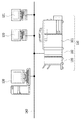
装置110は、画像形成装置101と、検品装置102と、フィニッシャ部103とから構成される。装置110は、画像形成、画像検品、フィニッシングまでを一貫して行うインライン検品方式を採用する。
The
画像形成装置101は、各種の入力データを処理し、紙などの記録媒体に画像を印刷出力する。検品装置102は、画像形成装置101から出力される印刷を受け取って、記録媒体上の画像の品質が一定の基準を満たしているか否かを検査する。フィニッシャ部103は、検品装置102で検査された記録媒体を受け取って外部に排出する。
The
装置110は、ネットワーク140を介してプリントサーバー130やクライアントPC120,121に接続されている。
The
[画像形成装置の構成]
図2は、画像形成装置101の構成の一例を示す図である。なお、画像形成装置101の行う各処理は、画像形成装置制御部203によって統括的に制御される。
[Configuration of Image Forming Apparatus]
FIG. 2 is a diagram illustrating an example of the configuration of the
同図において、入力画像処理部201は、紙原稿などをスキャナなどの画像読取装置で読み取り、画像データを作成する。そして、画像データは、画像形成装置制御部203に送られる。
In the figure, an input
NIC部202は、画像形成装置内部の画像データや装置情報をネットワーク経由で外部に送信する、NIC(Network Interface Card)である。
The NIC
画像形成装置制御部203は、入力されるデータや出力するデータを制御する役割を果たし、図示しないCPU(Central Processing Unit)による制御が行われる。画像形成装置制御部203に入力された画像データは、一旦メモリ部204に記憶される。記憶された画像データは、一時的に保持され、必要に応じて呼び出される。
The image forming
また、画像形成装置制御部203は、検品装置102の検品処理部500と接続されており、検品処理部500による検品処理に必要な情報の送受信を行う。また、画像形成装置制御部203は、画像形成装置101で印刷処理された印刷ジョブに関連して検品装置102で検品処理を実行できるように、印刷出力のタイミング情報、リファレンス画像データ、検品に必要な設定値及び検品処理した結果の情報を送受信する。
The image forming
プリント画像処理部205は、印刷するためのプリント画像処理を実施し、処理された画像がプリンタ部206に送られる。このプリント画像処理には、色空間変換処理、ハーフトーン処理、ガンマ補正、エッジ強調、解像度変換などの処理を含む。
The print
プリンタ部206は、記録媒体となる用紙を給紙し、プリント画像処理部205により作成された画像データを用紙上に順次印刷する。印刷された用紙はプリンタ部206から排紙されて検品装置102に送出される。
The
操作部207は、画像形成装置101が備える機能のうち、ユーザーが利用しようとする機能を選択・指示するために用いられるものである。操作部207は、例えば、液晶ディスプレイ(LCD:Liquid Crystal Display)や静電容量方式等によるタッチパネルなどにより構成される。
The
RIP部208(Raster Image Processer)は、入力されたPDLデータを解読し、印刷や表示が可能なビットマップデータに展開し、RIP画像データを生成する。 A RIP unit 208 (Raster Image Processor) decodes input PDL data, develops it into bitmap data that can be printed and displayed, and generates RIP image data.
図3は、画像形成装置101の機械構成を示す図である。
FIG. 3 is a diagram illustrating a mechanical configuration of the
画像形成装置101は、スキャナ部301、レーザ露光部302、感光ドラム303、作像部304、定着部305、給紙/搬送部306、及び、これらを制御する画像形成装置制御部203により構成される。
The
スキャナ部301は、原稿台に置かれた原稿に対して、照明を当てて原稿画像を光学的に読み取り、その像を電気信号に変換して画像データを作成する。
The
レーザ露光部302は、作成された画像データに応じて変調されたレーザ光などの光線を等角速度で回転する回転多面鏡(ポリゴンミラー)307に入射させ、反射走査光として感光ドラム303に照射する。
The
作像部304は、感光ドラム303を回転駆動し、帯電器によって帯電させ、上記レーザ露光部によって感光ドラム上に形成された潜像をトナーによって現像する。そのトナー像を用紙に転写し、その際に転写されずに感光ドラム上に残った微小トナーを回収するといった一連の電子写真プロセスの現像ユニット(現像ステーション)を4連持つことで実現している。シアン(C)、マゼンタ(M)、イエロー(Y)、ブラック(K)の順に並べられた4連の現像ユニットは、シアンステーションの作像開始から所定時間経過後に、マゼンタ、イエロー、ブラックの作像動作を順次実行していく。このタイミング制御によって、用紙上に色ずれのない、フルカラートナー像が転写される。本実施例はカラープリンタを想定しているが、これに限定されるものではなく、白黒プリンタの場合にはブラックの現像ユニットのみが搭載される。
The
定着部305は、ローラーやベルトの組み合わせによって構成され、ハロゲンヒータなどの熱源を内蔵し、上記作像部によってトナー像が転写された用紙上のトナーを、熱と圧力によって溶解、定着させる。給紙/搬送部306は、用紙カセットやペーパーデッキに代表される用紙収納庫を一つ以上持っており、上記プリンタ制御部の指示に応じて用紙収納庫に収納された複数の用紙の中から一枚分離し、作像部304、定着部305へ搬送する。用紙は搬送され、前述の現像ステーションによって、各色のトナー像が転写され、最終的にフルカラートナー像が用紙上に形成される。また、用紙の両面に画像形成する場合は、定着部305を通過した用紙を再度作像部304へ搬送する搬送経路を通るように制御する。画像形成装置全体を制御する画像形成装置制御部203は図2に示した各部と通信し、その指示に応じて制御を実行する。また、前述のスキャナ、レーザ露光、作像、定着、給紙/搬送の各部の状態を管理し、全体が調和を保って円滑に動作できるよう指示を行う。
The fixing
[検品装置の構成]
図4(a)は検品装置102の機械構成を概略的に示す図である。
[Configuration of inspection equipment]
FIG. 4A is a diagram schematically illustrating a mechanical configuration of the
画像形成装置101から印刷出力された用紙は、給紙ローラー401によって検品装置102に引き込まれる。その後、印刷出力された用紙が搬送ベルト402上を転送されて、搬送ベルト402上にある検品センサー403により用紙上の画像を読み取られて、用紙上の画像の品質について判定される。
The paper printed out from the
判定結果はフィニッシャ部103に送られる。判定が行われた後に、用紙410は排紙ローラー404から出力される。ここでは図示しないが、検品センサー403は両面印刷出力用紙にも対応できるように搬送ベルト402の下側からも検品センサーで読み取る構造であってもよい。
The determination result is sent to the
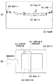
図4(b)は、搬送ベルト402の部分を上面視した例を示す図であり、ここで、検品センサー403は図示したように搬送されてきた用紙410の全面の画像をライン毎に読み取るラインセンサーである。 FIG. 4B is a diagram showing an example of a top view of the portion of the conveyor belt 402. Here, the inspection sensor 403 is a line that reads an image of the entire surface of the sheet 410 conveyed as shown in the drawing. It is a sensor.
画像読取用用紙照射装置411は、検品センサー403で用紙上の画像を読み取る際に用紙に光を照射する。 The image reading paper irradiation device 411 irradiates the paper with light when the inspection sensor 403 reads an image on the paper.
斜行検知用用紙照射装置412は、用紙が搬送ベルト402上を搬送される際に、用紙が搬送方向に対して斜行しているかどうかを検知する。搬送される用紙に対して斜め方向から照射することで、用紙の端部の影の画像を読み取り、斜行を検知する。本実施例では用紙端部の影画像の読み取りは検品センサー403で行う構成であるが、検品センサー403以外の別の読み取りセンサーを使用する構成でもよい。 The skew detection sheet irradiating device 412 detects whether the sheet is skewed with respect to the transport direction when the sheet is transported on the transport belt 402. By irradiating the conveyed paper from an oblique direction, a shadow image at the edge of the paper is read and skew is detected. In this embodiment, the shadow image at the edge of the sheet is read by the inspection sensor 403, but another reading sensor other than the inspection sensor 403 may be used.
図5は、検品装置102が備える検品処理部500の機能構成を示す図である。
FIG. 5 is a diagram illustrating a functional configuration of the
検品処理部500は、RIP画像データ又はスキャン画像データに基づいてリファレンス画像データを生成し、印刷された画像について検品処理を行うための制御を行う。なお、これらの検品処理は制御部507によって統括的に制御される。
The
スキャン画像データ処理部501は、検品センサー403で読み取った用紙上の画像が、電気信号に変換された印刷画像データに対し、スキャン画像処理を前補正処理として行うことで、スキャン画像データ513を生成する。スキャン画像処理は、用紙斜行補正、色補正処理、エッジ強調、解像度変換等の処理を含む。ここで、色補正処理は、検品センサー403での読み取りデバイスの色補正を行い、標準色空間に変換してスキャン画像生成をするものである。
The scan image
リファレンス画像データ生成部502は、画像形成装置制御部203より送られるRIP画像データ511、またはスキャン画像データ513を受け取り、リファレンス画像データ512を生成する。
A reference image
リファレンス画像データ生成部502は、印刷ジョブの設定に応じたプリント画像処理、又は印刷データに対するスキャン画像処理に相当する画像処理をRIP画像データに対し実行することも可能である。これにより、RIP画像データをそのままリファレンス画像データに使用した場合と比べ、検品対象である印刷画像データとの濃度差や特性差が小さいリファレンス画像データを生成できる。なお、リファレンス画像データ生成部502は、後述の画像比較・判定部504から受け取る検品判定結果515に基づき、スキャン画像データ513をリファレンス画像データの生成に使用するかを判断する。
The reference image
さらに、リファレンス画像データ生成部502は、生成されたリファレンス画像データに対し、検品判定基準514を決定し、判定基準生成を行う。例えば、濃度に関する検品判定基準として、濃度許容範囲を決定する。すなわち、スキャン画像データの濃度値が決定された濃度許容範囲に収まっていれば、一定の品質を有する画像であると判定するための基準となる。なお、検品判定基準については、図11を用いて後述する。
Further, the reference image
リファレンス画像データ記憶部503は、リファレンス画像データ生成部502で生成されたリファレンス画像データを記憶する。複数部印刷の場合、リファレンス画像データ記憶部503に記憶されたリファレンスデータを部ごとに読み出して使用することができる。
The reference image
画像比較・判定部504は、まず、リファレンス画像データ生成部502で生成されたリファレンス画像データ512と、スキャン画像データ処理部501で生成された検品対象となるスキャン画像データ513とを比較する。そして、比較結果から、リファレンス画像データ生成部502で決定された検品判定基準514に従って、リファレンス画像データに対する印刷画像データの等価性の判定を行う。
The image comparison /
また、画像比較・判定部504は検品判定結果515をリファレンス画像データ生成部502に送り、リファレンス画像データや検品判定基準の更新をさせる。検品判定基準の更新については、図11を用いて後述する。
Also, the image comparison /
画像比較・判定部504による判定の結果、リファレンス画像データと印刷画像データとが等価でないと判定された場合に、判定結果記憶部505は、該当するページのページ情報や検品判定内容などを記憶する。記憶された判定結果は、検品処理の結果としてデータベースにして利用可能となる。
As a result of determination by the image comparison /
判定結果表示部506は、判定結果記憶部505に記憶された判定結果をユーザーに対し、表示する。
The determination
制御部507は検品装置102各種の制御処理を行うとともに、画像形成装置101内の画像形成装置制御部203との画像データや印刷ジョブデータの転送を行う。さらに、上記の検品処理の判定結果を画像形成装置制御部203へと通知し、画像形成装置制御部203は判定結果が良であるか又は不良であるかに応じて、画像形成装置101の動作を制御する。
The
[フィニッシャの構成]
図6は、フィニッシャ部103の構成の一例を断面図である。
[Finisher configuration]
FIG. 6 is a cross-sectional view of an example of the configuration of the
検品装置102から排出された用紙は、フィニッシャ部103に入る。フィニッシャ部103は、エスケープトレイ601及び出力トレイ602を備え、検品装置102による判定結果に応じて切り替えて排出される。さらに、出力すべきジョブに対してステイプルモードが設定されている場合には、出力トレイに排出するよう制御する。その際には、用紙が出力トレイに排出される前に、用紙をジョブ毎にフィニッシャ内部の処理トレイ603に順次蓄えておき、該処理トレイ603上にてステープラ604にてバインドして、その上で、出力トレイ602へ、該記録用紙束を排出する。
The sheet discharged from the
転送パス切り替え部605は、検品装置102からの検品判定情報に応じて、印刷出力用紙の転送パスを切り替える。転送パスを切り替えることにより、印刷出力用紙をエスケープトレイ601もしくは出力トレイ602に転送することが可能である。
The transfer path switching unit 605 switches the transfer path of the print output paper according to the inspection determination information from the
用紙掃き寄せ部606は出力トレイ上に排出された用紙に対して、用紙排出方向と直行する方向にシフト動作を行う。用紙掃き寄せ部606が動作する場合は、動作しない場合に対してその排出された用紙をずらすことで、他の排出された用紙と区別して排出することができる。
The
図7は、フィニッシャ部103の機能構成を示す図である。
FIG. 7 is a diagram illustrating a functional configuration of the
画像形成装置101の画像形成装置制御部203と、フィニッシャ部103内のフィニッシャ制御部701とは、専用の通信線により接続される。
The image forming
フィニッシャ制御部701は、画像形成装置101から、ジョブに応じたフィニッシャ設定情報を受信し、受信した設定情報に基づいてフィニッシャ部103内の各機能を制御する制御部との間で通信を行う。
The
搬送パス駆動制御部702は、フィニッシャ制御部701から送信されたジョブの制御情報に基づいて各種フィニッシングユニットへ用紙を導く。例えば、ステイプル出力を行いたい場合には、ステープラ制御部703との通信を行い、ステープラ制御部703のステータス情報をフィニッシャ制御部701が受信して、ジョブの制御情報を送信し、ジョブの内容に応じたステープラ動作を行った後に出力する。
The transport path drive
[検品フロー]
本実施例として、上記の画像検品システムにおいて、印刷ジョブに基づいて生成されるRIP画像データと、当該印刷ジョブに従って印刷された用紙をスキャンして生成されたスキャン画像データとを用いる検品処理の処理手順について説明する。
[Inspection flow]
In this embodiment, in the above-described image inspection system, inspection processing using RIP image data generated based on a print job and scanned image data generated by scanning a sheet printed according to the print job The procedure will be described.
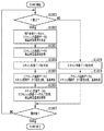
図8は、本実施例1における検品処理の処理手順を示すフロー図である。 FIG. 8 is a flowchart showing the processing procedure of the inspection processing in the first embodiment.
まず、S801では、画像形成装置制御部203は、NIC部202を介して印刷ジョブを受信する。なお、この印刷ジョブは、例えば、入力画像データと、部数、ページ数、画像処理内容等の内容を示す情報を含む。そして、画像形成装置制御部203は、この印刷ジョブを検品処理部500へ送信する。
First, in step S <b> 801, the image forming
S802では、画像形成装置制御部203は、その印刷ジョブが複数部数の印刷であるかを判定する。判定は、S801で受信した印刷ジョブが含む部数の情報を参照して判定する。
In step S <b> 802, the image forming
判定の結果、複数部印刷に係る同一の印刷ジョブではない(つまり、1部印刷を指示する印刷ジョブ)場合(S802;NO)、画像形成装置制御部203は、S803で、検品装置102に1部印刷ジョブに対する検品処理S900を実行させる(図9)。
As a result of the determination, if the print jobs are not the same for multiple copies (that is, a print job instructing one copy) (S802; NO), the image forming
一方、その印刷ジョブが複数部印刷と判定された場合(S802;YES)、画像形成装置制御部203は、S804で検品装置102に複数部印刷ジョブに対する検品処理S1000を実行させる(図10に示す処理)。
On the other hand, when it is determined that the print job is a plurality of copies (S802; YES), the image forming
図9は、本実施例1における検品装置102内の検品処理部500が実行する1部印刷ジョブに対する検品処理の処理手順を示すフロー図である。なお、1部印刷の検品処理S900は、検品処理部500内の制御部507によって実行される。
FIG. 9 is a flowchart illustrating a processing procedure of inspection processing for a one-copy print job executed by the
まず、S901では、制御部507は、画像形成装置制御部203から送信される印刷ジョブに係るRIP画像データをリファレンス画像データ生成部502に送信する。そして、リファレンス画像データ生成部502は、RIP画像データをリファレンス画像データとして設定する。
First, in step S <b> 901, the
なお、リファレンス画像データ生成部502は、受信したRIP画像データをそのままリファレンス画像データに設定してもよい。もしくは、検品処理部500が受信した印刷ジョブに基づいて実行されることとなる印刷処理の影響や、スキャナ特性に基づいて受信したRIP画像データをさらに画像処理したRIP画像データを、リファレンス画像データに設定することも可能である。これにより、実際に記録媒体上に形成される画像の色味や濃度を考慮したリファレンス画像データを生成することが可能となる。
Note that the reference image
リファレンス画像データ生成部502がRIP画像データをそのままリファレンス画像データとして使用するか、又は画像処理を施すかは、ユーザーが印刷ジョブ投入時に設定することもできる。もしくは、検品処理部500が印刷ジョブ情報に応じて設定するようにしてもよい。
Whether the reference image
また、S901では、リファレンス画像データ生成部502は、生成されたリファレンス画像データに対する検品判定基準も決定する。検品判定基準については、図11を用いて後に詳しく説明する。
In step S901, the reference image
S902では、制御部507は、S901で生成したリファレンス画像データと、検品判定基準とを、リファレンス画像データ記憶部503に記憶させる。
In step S902, the
S903では、制御部507は、スキャン画像データ処理部501で、印刷ジョブに基づいて画像形成装置101により印刷された用紙に対してスキャンを実行して、スキャン画像データを生成する。
In step S903, the
S904では、制御部507は、リファレンス画像データ記憶部503に記憶されているリファレンス画像データを読み出し、スキャン画像データ処理部501で生成したスキャン画像データと濃度比較を行う。そして、同じくリファレンス画像データ記憶部503に記憶されている検品判定基準に基づいて、用紙に出力された画像の良否について品質判定を行う。なお、検品判定基準に基づく品質判定の詳細については、図11を用いて後述する。
In step S <b> 904, the
S905では、制御部507は、印刷ジョブが最終ページまで完了したかを判定する。印刷ジョブが最終ページに達しない場合(S905;NO)、S901〜S904の処理を繰り返し実行する。一方、印刷ジョブが最終ページに達した場合(S905;YES)、検品処理を終了する。
In step S905, the
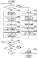
続いて、図10は、本実施例における検品装置102内の検品処理部500が有する制御部507が実行する複数部印刷検品処理の処理手順を示すフロー図である。
Next, FIG. 10 is a flowchart showing a processing procedure of a multi-part print inspection process executed by the
まず、S1001では、制御部507は、受信した印刷ジョブに関し、複数部印刷の開始の1部目の印刷物に係る処理であるかどうかを判断する。1部目の印刷物に対する処理であると判断された場合(S1001;YES)、S1002のフローへ移動する。一方、受信した印刷ジョブが2部目以降の印刷物に対する処理の場合(S1001;NO)、S1008のフローへ移動する。
In step S <b> 1001, the
ここで、複数部印刷の1部目の印刷物に対する検品処理におけるS1002〜S1005の処理フローにおけるステップのそれぞれは、前述の1部印刷の検品処理におけるS901〜S904の処理フローにおける各ステップと同様であるため、説明は省略する。 Here, each of the steps in the processing flow of S1002 to S1005 in the inspection processing for the first printed matter of the multiple copies is the same as each step in the processing flow of S901 to S904 in the above-described inspection processing for one copy. Therefore, explanation is omitted.
続いてS1006では、制御部507は、2部目以降の印刷物の品質判定において使用するリファレンス画像データを新たに生成する。
In step S <b> 1006, the
その際、制御部507は、1部目の検品処理において良品と判定されたスキャン画像データを、リファレンス画像データ生成部502を介して、リファレンス画像データ記憶部503に記憶させる。そして、リファレンス画像データ生成部502は、このスキャン画像データをリファレンス画像に設定する。また、リファレンス画像データの変更に合わせて、検品判定基準を更新し、リファレンス画像データ記憶部503に記憶する。検品判定基準の更新については、図11を用いて後述する。
At that time, the
最後に、S1007では、印刷ジョブが最終部まで完了したかを判定する。印刷ジョブが最終部に達しない場合(S1007;NO)、S1001へ戻る。一方、印刷ジョブが最終部に達した場合(S1007;YES)、検品処理が終了する。 Finally, in step S1007, it is determined whether the print job is completed up to the final copy. If the print job does not reach the final part (S1007; NO), the process returns to S1001. On the other hand, when the print job reaches the final part (S1007; YES), the inspection process ends.
次に、複数部印刷の2部目以降の印刷物に対する処理手順を説明する。S1001において、実行を開始する検品処理が1部目の印刷物に対する処理でないと判断された場合(S1001;NO)、S1008に進み、2部目以降の印刷物に対する品質判定がされる。 Next, a processing procedure for the second and subsequent printed materials of the multiple copies will be described. If it is determined in S1001 that the inspection process to be started is not a process for the first printed material (S1001; NO), the process proceeds to S1008, and quality determination is performed for the second and subsequent printed materials.
S1008では、S1004と同様に、スキャン画像データ処理部501は、印刷物に対しスキャンを実行して、スキャン画像データを生成する。
In step S1008, as in step S1004, the scan image
次に、S1009では、リファレンス画像データ記憶部503に記憶されているリファレンス画像データを読み出し、スキャン画像データ処理部501で生成したスキャン画像データと濃度比較を行う。ここで使用するリファレンス画像データは、S1006で1部目の印刷物に対する品質判定で良品と判定されたスキャン画像データである。そして、画像比較・判定部504は、S1006にて更新されて記憶されている検品判定基準をリファレンス画像データ記憶部503から読み出し、読み出した検品判定基準に基づいて品質判定を行う。
In step S <b> 1009, the reference image data stored in the reference image
[検品判定基準の決定方法]
次に、本実施例における検品判定基準の詳細について、図11を用いて説明する。
[Method for determining inspection criteria]
Next, details of the inspection determination criteria in this embodiment will be described with reference to FIG.
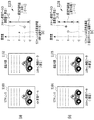
図11(a)は、図9のステップS901〜S904および図10のS1002〜S1005において、検品判定基準を用いた品質判定の具体例を説明するための図である。 FIG. 11A is a diagram for describing a specific example of quality determination using inspection determination criteria in steps S901 to S904 in FIG. 9 and S1002 to S1005 in FIG.
まず、リファレンス画像データ生成部502は、1部目のリファレンス画像データであるRIP画像データ1101の濃度を計算し、計算された濃度を濃度基準値に設定する。そして、リファレンス画像データ生成部502は、画像データ同士の比較によって良品か否かを判定するための濃度許容範囲を設定する。
First, the reference image
例えば、グラフ1103が示すように、リファレンス画像データ(1部目の印刷物の検品処理においてはRIP画像データ)の濃度を濃度基準値となる「0」に設定し、濃度許容範囲を「−2〜+2」に設定する。この設定された濃度許容範囲を本実施例では検品判定基準と称する。すなわち、濃度許容範囲は検品判定基準によって定まる。
For example, as indicated by a
濃度許容範囲は、1部目の印刷物に対応するリファレンス画像データであるRIP画像データ1101と、検品対象であるスキャン画像データ1102との間の関係において、印刷ジョブの設定に応じた画像処理を考慮した濃度許容範囲を設定することが望ましい。すなわち、濃度許容範囲は必ずしもRIP画像データの濃度を基準値としたものでなくても良い。
In the relationship between the
例えば、プリント画像処理およびスキャン画像処理によってスキャン画像データの濃度が濃く(暗くなる)なる場合、濃度許容範囲を「−10〜−6」と設定しても良い。また、これらの画像処理を考慮しないのであれば「−10〜+10」と濃度許容範囲を、後述する2部目以降の印刷物の検品処理における濃度許容範囲よりも大きく設定しても良い。 For example, when the density of the scanned image data is increased (darkened) by print image processing and scanned image processing, the density allowable range may be set to “−10 to −6”. If these image processes are not taken into consideration, the allowable density range of “−10 to +10” may be set to be larger than the allowable density range in the inspection process for the second and subsequent copies to be described later.
次に、画像比較・判定部504は、検品対象である印刷物のスキャン画像データ1102と、リファレンス画像データであるRIP画像データ1101との濃度差を算出し、算出された濃度差が濃度許容範囲内にあるかを判定する。
Next, the image comparison /
例えば、図11(a)に示すグラフ1103のように、RIP画像データ1101とスキャン画像データ1102の濃度差の値が「−1」と算出された場合、濃度許容範囲の「−2〜+2」に収まっている。画像比較・判定部504は、検品対象であるスキャン画像データ1102の濃度値が濃度許容範囲内あれば、良と判定する。
For example, when the value of the density difference between the
もし、濃度許容範囲を超える濃度差がある場合、画像比較・判定部504は、検品対象である印刷物の画像は不良であると判定する。すなわち、プリンタ部206の印刷不具合や印刷ジョブの設定ミスが要因となって、検品対象である印刷物のスキャン画像データに濃度異常が発生していることが想定される。
If there is a density difference that exceeds the allowable density range, the image comparison /
図11(b)は、図10のステップ1006〜S1009における複数部印刷の2部目以降の印刷物の検品処理における検品判定基準の決定、および、検品判定基準を用いた品質判定について説明するための図である。ここでは、10部目を処理対象とする場合について説明する。 FIG. 11B is a diagram for explaining the determination of the inspection determination criteria in the inspection processing of the second and subsequent printed materials in the steps 1006 to S1009 in FIG. 10 and the quality determination using the inspection determination criteria. FIG. Here, a case where the 10th copy is a processing target will be described.
1部目で品質判定の結果が良品の場合、画像比較・判定部504は、リファレンス画像データ記憶部503に1部目のスキャン画像データ1102を送信する。そして、2部目以降のリファレンス画像データを、スキャン画像データ1102に置き換えたリファレンス画像データ1104とする。
When the quality judgment result is good for the first copy, the image comparison /
また、画像比較・判定部504は、1部目の品質判定の結果に基づき、検品判定基準を更新する。例えば、グラフ1106に示すように、新たなリファレンス画像データ1104である1部目の印刷物のスキャン画像データの濃度が、濃度基準値「0」として設定される。そして、1部目の印刷物の検品処理に用いられていた濃度許容範囲よりも範囲の狭い「−1〜+1」が新たな濃度許容範囲に設定される。
The image comparison /
このように、2部目以降の印刷物の検品判定では、印刷ジョブの設定に応じたプリント画像処理や検品装置でのスキャン画像処理が施された1部目のスキャン画像データを、新たなリファレンス画像データとして使用できる。その結果、濃度変動に対してより厳しい濃度許容範囲を用いて検品をすることができる。 As described above, in the inspection determination of the second and subsequent copies, the first copy of the scanned image data that has been subjected to the print image processing according to the print job setting or the scan image processing in the inspection apparatus is used as a new reference image. Can be used as data. As a result, inspection can be performed using a stricter density tolerance range against density fluctuation.
例えば、グラフ1106が示すように、10部目のスキャン画像データ1105の濃度差が「0.5」と算出された場合、濃度許容範囲の「−1〜+1」に収まるため、検品の判定はOKとなる。もし、2部目以降の検品において、濃度許容範囲を超える濃度差がスキャン画像データ1105に発生した場合、画像比較・判定部504は、検品対象である印刷物を不良であると判定する。すなわち、プリンタ部206の印字や検品装置102の検品センサーなどの異常により、部ごとに濃度変動が発生したことが想定される。
For example, as shown in the
以上のように、複数部印刷の検品処理において、検品対象とする印刷物が何部目であるか応じてリファレンス画像データを変更し、変更されたリファレンス画像データに応じた検品判定基準を設定することにより、高い精度の検品が可能となる。 As described above, in the inspection process for multiple copies, the reference image data is changed according to the number of copies of the printed matter to be inspected, and the inspection determination standard according to the changed reference image data is set. Therefore, inspection with high accuracy becomes possible.
(実施例2)
[検品処理]
実施例2は、実施例1と同様の画像検品システムにおいて、RIP画像データとスキャン画像データを併用して生成したリファレンス画像データによる検品処理について説明する。なお、実施例2は、複数のページで共通に再利用することができるテンプレートデータと、ページごとにそれぞれ異なる種類の画像であるバリアブルデータを画像処理手段で合成し、その合成データを印刷するバリアブル印刷に係る処理を実施する。
(Example 2)
[Inspection processing]
In the second embodiment, an inspection process using reference image data generated by using both RIP image data and scan image data in the same image inspection system as in the first embodiment will be described. In the second embodiment, template data that can be reused in common on a plurality of pages and variable data that is different types of images for each page are combined by an image processing unit, and the combined data is printed. Perform processing related to printing.
図12は、実施例2における検品処理の処理手順を示すフロー図である。 FIG. 12 is a flowchart illustrating a processing procedure of inspection processing in the second embodiment.
まず、S1201において、NIC部202が印刷ジョブを受信する。その際、印刷ジョブに係る情報には、入力画像データと、部数、ページ数、画像処理内容等のジョブ設定に係る情報が含まれる。NIC部202が受信した印刷ジョブは、検品処理部500へ転送される。
First, in step S1201, the
次に、S1202において、画像形成装置制御部203は、その印刷ジョブがバリアブル印刷を指示する内容であるかどうかを判定する。当該判定は、S1201で受信した印刷ジョブに含まれるバリアブル印刷情報が示す内容に基づいて行うことができる。
In step S <b> 1202, the image forming
受信した印刷ジョブがバリアブル印刷を指示するものではないと画像形成装置制御部203が判定した場合(S1202;NO)、次にS1203において、検品処理部500に1部印刷ジョブに対する検品処理S900を実行させる。この1部印刷ジョブに対する検品処理S900は、実施例1で説明した1部印刷検品処理と同じ処理である。
If the image forming
一方、受信した印刷ジョブがバリアブル印刷を指示するものであると画像形成装置制御部203が判定した場合(S1202;YES)、次にS1204において、検品処理部500にバリアブル印刷ジョブに対する検品処理S1300を実行させる。
On the other hand, when the image forming
図13は、本実施例2における検品装置102内の検品処理部500が有する制御部507が実行する、バリアブル印刷検品処理(S1300)の処理手順を示すフロー図である。
FIG. 13 is a flowchart illustrating a processing procedure of the variable print inspection process (S1300) executed by the
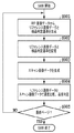
まず、S1301において、制御部507は、受信した印刷ジョブに対して、バリアブル印刷の最初の1ページ目に対する処理であるかどうかを判断する。ここで、バリアブル印刷における1ページ目に係る処理であると制御部507が判断した場合(S1301;YES)、S1302に進む。一方、バリアブル印刷の2ページ目以降の場合(S1301;NO)、S1308に進む。
First, in step S1301, the
ここで、複数部印刷の1ページ目に対する検品処理におけるS1302〜S1305のフローは、実施例1で説明したS1002〜S1005のフローと同様であるため、説明を省略する。 Here, since the flow of S1302 to S1305 in the inspection process for the first page of the multiple copies is the same as the flow of S1002 to S1005 described in the first embodiment, the description thereof is omitted.
次に、S1306において制御部507は、2ページ目以降にも使用するリファレンス画像データとして、1ページ目の検品判定で良品と判定されたスキャン画像データをリファレンス画像データ記憶部503に記憶する。また、リファレンス画像データの変更に合わせて、検品判定基準を更新し、リファレンス画像データ記憶部503に記憶する。
Next, in step S <b> 1306, the
最後に、S1307では、制御部507が、印刷ジョブが最終ページまで完了したかを判定する。印刷ジョブが最終ページに達しない場合(S1307;NO)、S1301へ戻る。一方、印刷ジョブが最ページに達した場合(S1307;YES)、S1313では、制御部507が、印刷ジョブが最終部まで完了したかを判定する。印刷ジョブが最終部に達しない場合(S1313;NO)、印刷ジョブは複数部のバリアブル印刷となるため、S1314では、実施例1で示した複数部印刷の検品処理S1000へ移る。一方印刷ジョブが最終部に達した場合(S1313;YES)、検品処理を完了する。
Finally, in step S1307, the
次に、バリアブル印刷の2ページ目以降に対する検品処理におけるフローを説明する。S1301において、実行を開始する検品処理が1ページ目でないと判断された場合(S1301;NO)、S1308では、制御部507が2ページ目のRIP画像データについて、バリアブル領域とテンプレート領域とに分類する。この分類は、S1201で受信した印刷ジョブに含まれるバリアブル印刷ジョブが示すバリアブル・テンプレート領域情報に基づいて行われる。
Next, a flow in the inspection process for the second and subsequent pages of variable printing will be described. If it is determined in S1301 that the inspection process to be started is not the first page (S1301; NO), in S1308, the
S1309では、制御部507は、リファレンス画像データ記憶部503に記憶されているリファレンス画像データにおけるバリアブル領域を、S1308で分類したRIP画像のバリアブル領域に置き換えたリファレンス画像データを生成する。同時に、制御部507は、新たなリファレンス画像データに関する検品判定基準を作成し、置き換えることで、2ページ目以降の検品判定基準も更新する。なお、S1309におけるリファレンス画像データ生成方法については、後に説明する。
In step S1309, the
次に、S1310では、制御部507は、S1309で生成したリファレンス画像データと検品判定基準を、リファレンス画像データ記憶部503に記憶させる。
Next, in S1310, the
S1311では、S1304と同様に、スキャン画像データ処理部501が印刷物をスキャンし、スキャン画像データを生成する。そして、S1312では、画像比較・判定部504は、リファレンス画像データ記憶部503に記憶されているリファレンス画像データを読み出し、スキャン画像データ処理部501で生成したスキャン画像データと濃度比較を行う。
In S1311, the scan image
以上のように、バリアブル印刷では、リファレンス画像データとして1ページ目のスキャン画像データを用い、2ページ目以降はRIP画像のバリアブル領域のみを置き換えることでき、これにより効果的な濃度の検品処理が可能となる。 As described above, in variable printing, the scan image data of the first page can be used as the reference image data, and only the variable area of the RIP image can be replaced for the second and subsequent pages, thereby enabling effective density inspection processing. It becomes.
[バリアブル印刷におけるリファレンス生成方法]
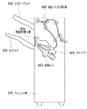
次に、本実施例におけるバリアブル印刷の検品処理におけるS1309で実施される、バリアブル領域のリファレンス画像データ生成方法について、図14を用いて説明する。リファレンス画像データは、例えば、図14(a)に示す(1)〜(3)の3つの方法により生成が可能である。
[Reference generation method in variable printing]
Next, the reference image data generation method for the variable area, which is performed in S1309 in the inspection process for variable printing in the present embodiment, will be described with reference to FIG. The reference image data can be generated by, for example, the three methods (1) to (3) shown in FIG.
まず、生成方法(1)は、RIP画像データに画像処理を加えず、そのままリファレンス画像データとして使用する方法であり、従来の検品処理と同様の方法である。なお、上記実施例では、バリアブル領域のみを置き換える例について説明したが、生産性を重視する場合に、この生成方法(1)のように実施すること可能である。 First, the generation method (1) is a method in which image processing is not applied to RIP image data but is used as it is as reference image data, and is the same method as conventional inspection processing. In the above-described embodiment, an example in which only the variable area is replaced has been described. However, when productivity is important, the generation method (1) can be performed.
生成方法(3)は、RIP画像データに対し、印刷ジョブに応じてプリント画像処理やスキャン画像処理を施すものである。これにより、例えば、RIP画像データと、印刷物に係るスキャン画像データとの間の濃度差を考慮した処理が可能となる方法である。 In the generation method (3), print image processing or scan image processing is performed on RIP image data in accordance with a print job. Thereby, for example, the processing can be performed in consideration of the density difference between the RIP image data and the scanned image data relating to the printed matter.
また、生成方法(2)は、生成方法(3)と同様にRIP画像データに画像処理を施しリファレンス画像データを生成する手法であり、生成方法(3)と比べてより簡易的な画像処理を用いる方法である。 Further, the generation method (2) is a method of generating reference image data by performing image processing on the RIP image data in the same manner as the generation method (3), and is simpler than the generation method (3). This method is used.
次に、図14(b)に、リファレンス画像データの生成方法(2)で使用する濃度変換テーブルの例を示す。図14(b)のように、検品処理によってリファレンス画像データ記憶部503に記憶されたRIP画像データに対するスキャン画像データの濃度値の関係性を、濃度変換テーブル1400としてリファレンス画像データ記憶部503に記憶する。
Next, FIG. 14B shows an example of a density conversion table used in the reference image data generation method (2). As shown in FIG. 14B, the relationship of the density value of the scanned image data to the RIP image data stored in the reference image
リファレンス画像データ生成部502は、RIP画像データに対し、この濃度変換テーブル1400を用いた濃度変換処理を行うことで、簡易的にRIP画像データからスキャン画像データを生成する際の画像処理を再現する。例えば、RIP画像データのある画素の濃度値が「100」の場合、濃度変換テーブル1400から、リファレンス画像データのその画素の濃度値を「90」に変換することができる。
The reference image
これにより、生成方法(1)と比べて画像処理による濃度変動が少なく、生成方法(3)と比べリファレンス画像データ生成のRIP画像データの画像処理時間も短くした、リファレンス画像データを生成できる。 Thereby, it is possible to generate reference image data in which density variation due to image processing is less than that in the generation method (1) and image processing time of RIP image data for generating reference image data is shorter than that in the generation method (3).
以上の3つのリファレンス画像データ生成方法の選択方法として、図14(a)に示すように、次の(A)、(B)の2つの方法があげられる。選択方法(A)は、制御部507が、バリアブル領域の属性情報に基づいてリファレンス画像データ生成方法を選択する。バリアブル領域の属性情報は、印刷ジョブに含まれている。例えば、バリアブル領域の属性が文字の場合、文字の濃度よりも文字自体が正しく印字されているかの検品が求められる。そのため、属性が文字のバリアブルデータに対しては、リファレンス画像データ生成部502は前述の生成方法(1)を選択すればよい。
As methods for selecting the above three reference image data generation methods, there are the following two methods (A) and (B) as shown in FIG. In the selection method (A), the
また、バリアブル領域の属性が写真や絵の場合、制御部507は濃度に関する検品に高い精度が必要と判断し、リファレンス画像データ生成部502は生成方法(3)を用いてリファレンス画像データを生成すればよい。
If the attribute of the variable region is a photograph or a picture, the
一方、選択方法(B)では、ユーザーが、印刷ジョブ設定と同時に指定する検品モード設定に基づいてリファレンス画像データ生成方法を選択する。例えば、ユーザーが検品処理の生産重視モードを選択した場合、前述の生成方法(1)のようにRIP画像データをそのままリファレンス画像データとして使用することで、リファレンス画像データ生成のための画像処理が不要となる。そのため、画像検品システムの高い生産性を維持できる。 On the other hand, in the selection method (B), the user selects the reference image data generation method based on the inspection mode setting specified at the same time as the print job setting. For example, when the user selects the production-oriented mode of inspection processing, the image processing for generating the reference image data is unnecessary by using the RIP image data as the reference image data as in the generation method (1) described above. It becomes. Therefore, high productivity of the image inspection system can be maintained.
一方、ユーザーが検品処理の精度重視モードを選択した場合、リファレンス画像データ生成部502は生成方法(3)を用いてリファレンス画像データを生成する。その場合、RIP画像データの画像処理時間の分、ある程度の画像検品システムの生産性の低下が生じるものの、濃度に関して高い精度で検品ができる。また、ユーザーが検品処理の生産性・精度両立モードを選択した場合、リファレンス画像データ生成部502は生成方法(2)を用いてリファレンス画像データを生成すればよい。
On the other hand, when the user selects the accuracy-oriented mode of the inspection process, the reference image
以上のように、バリアブル印刷の検品処理に対し、制御部507もしくはユーザーがバリアブル領域のリファレンス画像データの生成方法を切り替えることで、検品対象の画像の属性やユーザーが求める検品モードに応じた検品処理を実現できる。
As described above, the inspection processing according to the attribute of the image to be inspected and the inspection mode requested by the user by switching the generation method of the reference image data in the variable area by the
なお、実施例で説明した画像検品システムに係る動作を実行させるためのプログラムをコンピューターに読み取らせて、各種の動作をコンピューターに行わせるようにしてもよい。 The computer may be caused to read various programs for causing the computer to read a program for executing the operation related to the image inspection system described in the embodiment.
Claims (6)
前記画像の印刷される第1および第2の印刷物をスキャンして、第1および第2のスキャン画像を生成するスキャン画像生成手段と、
前記第1のスキャン画像の濃度値を求め、前記第1のスキャン画像の濃度値が前記判定基準によって定まる前記範囲内にある場合に、前記第1のスキャン画像をリファレンス画像に設定する設定手段と、
前記第2のスキャン画像の濃度値を求め、前記第2のスキャン画像の濃度値が前記判定基準によって定まる前記範囲内にあるかどうかを判定する判定手段と
を備えることを特徴とする画像検品装置。 A determination reference generation means for determining a density value of an image and generating a determination reference that defines a density range based on the density value;
Scan image generating means for generating first and second scan images by scanning the first and second printed matter on which the image is printed;
Setting means for obtaining a density value of the first scan image and setting the first scan image as a reference image when the density value of the first scan image is within the range determined by the determination criterion; ,
An image inspection apparatus comprising: a determination unit that calculates a density value of the second scan image and determines whether the density value of the second scan image is within the range determined by the determination criterion. .
前記判定基準生成手段は、前記画像処理手段により処理された前記画像の濃度値に基づいて判定基準を生成する
ことを特徴とする請求項1に記載の画像検品装置。 Image processing means for processing the image so as to reduce a characteristic difference between the image and the scanned image;
The image inspection apparatus according to claim 1, wherein the determination criterion generation unit generates a determination criterion based on a density value of the image processed by the image processing unit.
前記判定基準生成手段は、前記リファレンス画像の濃度値を基準にして濃度の範囲を定めた、前記第2の印刷物に使用される、前記第1の印刷物に使用される判定基準とは異なる判定基準を生成し、
前記第2の印刷物に使用される判定基準によって定まる濃度の範囲は、前記第1の印刷物に使用される判定基準によって定まる濃度の範囲よりも小さく、
前記判定手段は、前記第2の印刷物に対応する前記第2のスキャン画像の濃度値を求め、前記第2のスキャン画像の濃度値が前記第2の印刷物に使用される判定基準によって定まる前記範囲内にあるかどうかを判定する
ことを特徴とする請求項1又は2に記載の画像検品装置。 When the first and second printed materials are printed on a plurality of copies for one print job, and the second printed material is printed after the first printed material,
The determination criterion generation unit uses a determination range different from the determination criterion used for the first printed matter, which is used for the second printed matter, in which a density range is defined based on the density value of the reference image. Produces
The density range determined by the criterion used for the second printed material is smaller than the density range determined by the criterion used for the first printed material,
The determination unit obtains a density value of the second scan image corresponding to the second printed material, and the range determined by a determination criterion used for the second printed material is a density value of the second scan image. The image inspection apparatus according to claim 1, wherein it is determined whether or not the image inspection apparatus is within the image inspection apparatus.
前記判定基準生成手段は、前記第2の印刷物の前記テンプレート領域に使用される判定基準として、前記第1の印刷物に対応する前記リファレンス画像の濃度値を基準にした濃度の範囲を定めた判定基準を生成し、前記第2の印刷物の前記バリアブル領域に使用される判定基準として、前記第2の印刷物に印刷されるべき画像の濃度値を基準にした濃度の範囲を定めた判定基準を生成し、
前記判定手段は、前記第2の印刷物に対応する前記第2のスキャン画像の濃度値を求め、前記第2のスキャン画像の濃度値が前記第2の印刷物に使用される判定基準によって定まる前記範囲内にあるかどうかを判定する
ことを特徴とする請求項1又は2に記載の画像検品装置。 The first and second printed materials are printed materials of different pages among printed materials based on a print job composed of a plurality of pages, and the same image is printed on the first printed material and the second printed material. If the area and variable area where different images are printed,
The determination criterion generation unit determines a density range based on a density value of the reference image corresponding to the first printed material as a determination criterion used for the template region of the second printed material. As a criterion used for the variable area of the second printed matter, a criterion that defines a density range based on a density value of an image to be printed on the second printed matter is generated. ,
The determination unit obtains a density value of the second scan image corresponding to the second printed material, and the range determined by a determination criterion used for the second printed material is a density value of the second scan image. The image inspection apparatus according to claim 1, wherein it is determined whether or not the image inspection apparatus is within the image inspection apparatus.
前記画像の印刷される第1および第2の印刷物をスキャンして、第1および第2のスキャン画像を生成するスキャン画像生成ステップと、
前記第1のスキャン画像の濃度値を求め、前記第1のスキャン画像の濃度値が前記判定基準によって定まる前記範囲内にある場合に、前記第1のスキャン画像をリファレンス画像に設定する設定ステップと、
前記第2のスキャン画像の濃度値を求め、前記第2のスキャン画像の濃度値が前記判定基準によって定まる前記範囲内にあるかどうかを判定する判定ステップと
を備えることを特徴とする画像検品方法。 A determination criterion generation step for determining a density value of an image and generating a determination criterion that defines a density range based on the density value;
A scan image generation step of generating first and second scan images by scanning the first and second printed matter on which the image is printed;
A setting step of obtaining a density value of the first scan image and setting the first scan image as a reference image when the density value of the first scan image is within the range determined by the determination criterion; ,
An image inspection method comprising: determining a density value of the second scan image; and determining whether the density value of the second scan image is within the range determined by the determination criterion. .
Priority Applications (2)
| Application Number | Priority Date | Filing Date | Title |
|---|---|---|---|
| JP2012109443A JP2013239762A (en) | 2012-05-11 | 2012-05-11 | Image inspection apparatus, image inspection system, image inspection method, and computer program |
| US13/873,757 US20130301083A1 (en) | 2012-05-11 | 2013-04-30 | Image inspection device, image inspection system, image inspection method, and computer program |
Applications Claiming Priority (1)
| Application Number | Priority Date | Filing Date | Title |
|---|---|---|---|
| JP2012109443A JP2013239762A (en) | 2012-05-11 | 2012-05-11 | Image inspection apparatus, image inspection system, image inspection method, and computer program |
Publications (2)
| Publication Number | Publication Date |
|---|---|
| JP2013239762A true JP2013239762A (en) | 2013-11-28 |
| JP2013239762A5 JP2013239762A5 (en) | 2015-06-25 |
Family
ID=49548391
Family Applications (1)
| Application Number | Title | Priority Date | Filing Date |
|---|---|---|---|
| JP2012109443A Pending JP2013239762A (en) | 2012-05-11 | 2012-05-11 | Image inspection apparatus, image inspection system, image inspection method, and computer program |
Country Status (2)
| Country | Link |
|---|---|
| US (1) | US20130301083A1 (en) |
| JP (1) | JP2013239762A (en) |
Cited By (8)
| Publication number | Priority date | Publication date | Assignee | Title |
|---|---|---|---|---|
| JP2017134281A (en) * | 2016-01-28 | 2017-08-03 | コニカミノルタ株式会社 | Image forming device |
| JP2019077054A (en) * | 2017-10-20 | 2019-05-23 | コニカミノルタ株式会社 | Image formation system and program |
| JP2019136938A (en) * | 2018-02-09 | 2019-08-22 | コニカミノルタ株式会社 | Device, method and program for image formation processing |
| JP2020037201A (en) * | 2018-09-03 | 2020-03-12 | コニカミノルタ株式会社 | Image forming apparatus, image formation method and program |
| JP2020116746A (en) * | 2019-01-18 | 2020-08-06 | コニカミノルタ株式会社 | Reference image generation device, image formation system, reference image generation method, and reference image generation program |
| JP2021024139A (en) * | 2019-07-31 | 2021-02-22 | 株式会社リコー | Printer, gradation correction device, gradation correction program, and gradation correction method |
| JP2021191634A (en) * | 2020-01-06 | 2021-12-16 | コニカミノルタ株式会社 | Image formation apparatus and image formation method |
| JP7379107B2 (en) | 2019-11-13 | 2023-11-14 | キヤノン株式会社 | Information processing device and its control method |
Families Citing this family (12)
| Publication number | Priority date | Publication date | Assignee | Title |
|---|---|---|---|---|
| JP6455016B2 (en) * | 2013-08-27 | 2019-01-23 | 株式会社リコー | Image inspection apparatus, image forming system, and image inspection method |
| JP6299708B2 (en) * | 2015-09-01 | 2018-03-28 | コニカミノルタ株式会社 | Image forming apparatus, image forming system, and management apparatus |
| EP3381178B1 (en) | 2015-11-24 | 2021-12-22 | Dover Europe Sàrl | Quality monitoring arrangement and method in an industrial printer system |
| US10766253B2 (en) | 2016-10-07 | 2020-09-08 | Hewlett-Packard Development Company, L.P. | Sideband signal for fluid ejection |
| JP2020019250A (en) | 2018-08-02 | 2020-02-06 | キヤノン株式会社 | Image processing apparatus, image processing method and program |
| US11964497B2 (en) * | 2018-09-12 | 2024-04-23 | David Wachs | Mechanical handwriting quality control method |
| US20220266613A1 (en) * | 2018-09-12 | 2022-08-25 | David Wachs | Mechanical handwriting barcode control method |
| JP7247515B2 (en) * | 2018-10-23 | 2023-03-29 | コニカミノルタ株式会社 | Image inspection device and image inspection program |
| JP2020088828A (en) * | 2018-11-30 | 2020-06-04 | コニカミノルタ株式会社 | Image reading device |
| JP2020098980A (en) * | 2018-12-17 | 2020-06-25 | セイコーエプソン株式会社 | Image reading device, image reading method, and image reading system |
| US11599317B2 (en) | 2020-06-24 | 2023-03-07 | Konica Minolta, Inc. | Image forming apparatus, method, and program |
| JP2022051444A (en) * | 2020-09-18 | 2022-03-31 | 富士フイルムビジネスイノベーション株式会社 | Inspection device, image forming apparatus, and inspection program |
Citations (3)
| Publication number | Priority date | Publication date | Assignee | Title |
|---|---|---|---|---|
| JPH04353452A (en) * | 1991-05-31 | 1992-12-08 | Dainippon Printing Co Ltd | Method and apparatus for inspecting printed matter |
| JP2005271331A (en) * | 2004-03-24 | 2005-10-06 | Fuji Xerox Co Ltd | Image inspection device |
| JP2012000876A (en) * | 2010-06-17 | 2012-01-05 | Konica Minolta Business Technologies Inc | Variable printing inspection device and variable printing inspection method |
Family Cites Families (5)
| Publication number | Priority date | Publication date | Assignee | Title |
|---|---|---|---|---|
| US20040179717A1 (en) * | 2003-03-12 | 2004-09-16 | Dainippon Screen Mfg. Co., Ltd. | Printing system, method of inspecting print data, method of classifying print inspection result and program |
| JP5057186B2 (en) * | 2010-06-29 | 2012-10-24 | ブラザー工業株式会社 | Image reading apparatus, scanner driver, and image storage method |
| JP5786420B2 (en) * | 2010-07-01 | 2015-09-30 | 株式会社リコー | Image output apparatus, image inspection system, and density correction method |
| JP5678595B2 (en) * | 2010-11-15 | 2015-03-04 | 株式会社リコー | INSPECTION DEVICE, INSPECTION METHOD, INSPECTION PROGRAM, AND RECORDING MEDIUM CONTAINING THE PROGRAM |
| US8605303B2 (en) * | 2011-01-18 | 2013-12-10 | Xerox Corporation | Content-aware image quality defect detection in printed documents |
-
2012
- 2012-05-11 JP JP2012109443A patent/JP2013239762A/en active Pending
-
2013
- 2013-04-30 US US13/873,757 patent/US20130301083A1/en not_active Abandoned
Patent Citations (3)
| Publication number | Priority date | Publication date | Assignee | Title |
|---|---|---|---|---|
| JPH04353452A (en) * | 1991-05-31 | 1992-12-08 | Dainippon Printing Co Ltd | Method and apparatus for inspecting printed matter |
| JP2005271331A (en) * | 2004-03-24 | 2005-10-06 | Fuji Xerox Co Ltd | Image inspection device |
| JP2012000876A (en) * | 2010-06-17 | 2012-01-05 | Konica Minolta Business Technologies Inc | Variable printing inspection device and variable printing inspection method |
Cited By (13)
| Publication number | Priority date | Publication date | Assignee | Title |
|---|---|---|---|---|
| JP2017134281A (en) * | 2016-01-28 | 2017-08-03 | コニカミノルタ株式会社 | Image forming device |
| JP2019077054A (en) * | 2017-10-20 | 2019-05-23 | コニカミノルタ株式会社 | Image formation system and program |
| JP7040087B2 (en) | 2018-02-09 | 2022-03-23 | コニカミノルタ株式会社 | Image forming processing device, image forming processing method and image forming processing program |
| JP2019136938A (en) * | 2018-02-09 | 2019-08-22 | コニカミノルタ株式会社 | Device, method and program for image formation processing |
| JP7147383B2 (en) | 2018-09-03 | 2022-10-05 | コニカミノルタ株式会社 | Image forming apparatus, image forming method and program |
| JP2020037201A (en) * | 2018-09-03 | 2020-03-12 | コニカミノルタ株式会社 | Image forming apparatus, image formation method and program |
| JP2022008344A (en) * | 2019-01-18 | 2022-01-13 | コニカミノルタ株式会社 | Reference image generation device, reference image generation method and reference image generation program |
| JP2020116746A (en) * | 2019-01-18 | 2020-08-06 | コニカミノルタ株式会社 | Reference image generation device, image formation system, reference image generation method, and reference image generation program |
| JP2021024139A (en) * | 2019-07-31 | 2021-02-22 | 株式会社リコー | Printer, gradation correction device, gradation correction program, and gradation correction method |
| JP7379107B2 (en) | 2019-11-13 | 2023-11-14 | キヤノン株式会社 | Information processing device and its control method |
| JP2021191634A (en) * | 2020-01-06 | 2021-12-16 | コニカミノルタ株式会社 | Image formation apparatus and image formation method |
| JP7243771B2 (en) | 2020-01-06 | 2023-03-22 | コニカミノルタ株式会社 | Image forming apparatus and image forming method |
| JP7468729B2 (en) | 2020-01-06 | 2024-04-16 | コニカミノルタ株式会社 | Image forming apparatus and image forming method |
Also Published As
| Publication number | Publication date |
|---|---|
| US20130301083A1 (en) | 2013-11-14 |
Similar Documents
| Publication | Publication Date | Title |
|---|---|---|
| JP2013239762A (en) | Image inspection apparatus, image inspection system, image inspection method, and computer program | |
| JP5822503B2 (en) | Inspection system, inspection system control method and program | |
| US8780378B2 (en) | Inspection apparatus, inspection method, inspection system, and storage medium | |
| US8958116B2 (en) | Inspection apparatus, inspection system, inspection method, and storage medium | |
| US20200019353A1 (en) | Image inspection system, image inspection method, non-transitory computer-readable recording medium storing image inspection program | |
| US9146516B2 (en) | Image forming apparatus that performs inspection of printed matter, method of controlling the same, and storage medium | |
| US20110299862A1 (en) | Printing apparatus, method for controlling the same, and storage medium | |
| US8000618B2 (en) | Image formation device and image formation method | |
| JP2013166296A (en) | Product checking system, control method of product checking system, and program | |
| JP2011137736A (en) | Image processing apparatus, control method of the same, and program | |
| JP2013103407A (en) | Printing apparatus, method for controlling printing apparatus, and program | |
| JP2020154016A (en) | Image formation device and image inspection method | |
| US8107845B2 (en) | Printing apparatus and printing method | |
| JP2012231312A (en) | Sheet processing apparatus, control method of the same, and program | |
| JP2021067914A (en) | Image forming apparatus, image forming method, and program | |
| JP2008052115A (en) | Printing device, printing execution method therefor, and program of printing execution | |
| JP2021068390A (en) | Image forming apparatus, image forming method, and program | |
| JP2012232561A (en) | Sheet processor, method for controlling the same and program | |
| US11461600B2 (en) | Image forming apparatus, method, and program | |
| JP2006289827A (en) | Image processor, image processing method and program | |
| JP2013233764A (en) | System, method, and program of print image inspection | |
| JP6039296B2 (en) | Image forming apparatus, control method therefor, and program | |
| JP2016002658A (en) | Image formation device, method for control thereof, and program | |
| JP2021097365A (en) | Information processing device, printing control method, image formation system, and program | |
| US20230102352A1 (en) | Inspection system, method of controlling the system, printing apparatus, inspection apparatus, and program |
Legal Events
| Date | Code | Title | Description |
|---|---|---|---|
| A521 | Written amendment |
Free format text: JAPANESE INTERMEDIATE CODE: A523 Effective date: 20150501 |
|
| A621 | Written request for application examination |
Free format text: JAPANESE INTERMEDIATE CODE: A621 Effective date: 20150501 |
|
| A977 | Report on retrieval |
Free format text: JAPANESE INTERMEDIATE CODE: A971007 Effective date: 20160426 |
|
| A131 | Notification of reasons for refusal |
Free format text: JAPANESE INTERMEDIATE CODE: A131 Effective date: 20160517 |
|
| A02 | Decision of refusal |
Free format text: JAPANESE INTERMEDIATE CODE: A02 Effective date: 20161115 |