JP2013213350A - Supporting member attachment structure, construction method for support structure, and photovoltaic power generation system using supporting member attachment structure - Google Patents
Supporting member attachment structure, construction method for support structure, and photovoltaic power generation system using supporting member attachment structure Download PDFInfo
- Publication number
- JP2013213350A JP2013213350A JP2012084117A JP2012084117A JP2013213350A JP 2013213350 A JP2013213350 A JP 2013213350A JP 2012084117 A JP2012084117 A JP 2012084117A JP 2012084117 A JP2012084117 A JP 2012084117A JP 2013213350 A JP2013213350 A JP 2013213350A
- Authority
- JP
- Japan
- Prior art keywords
- screw
- support
- support member
- roof tile
- head
- Prior art date
- Legal status (The legal status is an assumption and is not a legal conclusion. Google has not performed a legal analysis and makes no representation as to the accuracy of the status listed.)
- Pending
Links
Images


Classifications
-
- Y—GENERAL TAGGING OF NEW TECHNOLOGICAL DEVELOPMENTS; GENERAL TAGGING OF CROSS-SECTIONAL TECHNOLOGIES SPANNING OVER SEVERAL SECTIONS OF THE IPC; TECHNICAL SUBJECTS COVERED BY FORMER USPC CROSS-REFERENCE ART COLLECTIONS [XRACs] AND DIGESTS
- Y02—TECHNOLOGIES OR APPLICATIONS FOR MITIGATION OR ADAPTATION AGAINST CLIMATE CHANGE
- Y02B—CLIMATE CHANGE MITIGATION TECHNOLOGIES RELATED TO BUILDINGS, e.g. HOUSING, HOUSE APPLIANCES OR RELATED END-USER APPLICATIONS
- Y02B10/00—Integration of renewable energy sources in buildings
- Y02B10/10—Photovoltaic [PV]
-
- Y—GENERAL TAGGING OF NEW TECHNOLOGICAL DEVELOPMENTS; GENERAL TAGGING OF CROSS-SECTIONAL TECHNOLOGIES SPANNING OVER SEVERAL SECTIONS OF THE IPC; TECHNICAL SUBJECTS COVERED BY FORMER USPC CROSS-REFERENCE ART COLLECTIONS [XRACs] AND DIGESTS
- Y02—TECHNOLOGIES OR APPLICATIONS FOR MITIGATION OR ADAPTATION AGAINST CLIMATE CHANGE
- Y02E—REDUCTION OF GREENHOUSE GAS [GHG] EMISSIONS, RELATED TO ENERGY GENERATION, TRANSMISSION OR DISTRIBUTION
- Y02E10/00—Energy generation through renewable energy sources
- Y02E10/50—Photovoltaic [PV] energy
Abstract
Description
本発明は、太陽電池モジュール等の構造物を屋根等の被設置物に設置するのに用いられる支持部材の取付け構造、支持構造の施工方法、及び支持部材の取付け構造を用いた太陽光発電システムに関する。 The present invention relates to a support member mounting structure, a support structure construction method, and a solar power generation system using the support member mounting structure, which are used to install a structure such as a solar cell module on an object to be installed such as a roof. About.
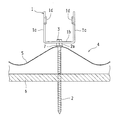
例えば、特許文献1では、図19に示すように屋根の瓦101に孔を開け、ボルト102を瓦101の孔に通して、ボルト102の下端を屋根の野地板もしくは垂木103に固定し、ボルト102の上端に桟104を固定して、桟104上に太陽電池モジュールを載せて支持している。
For example, in
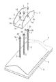
また、特許文献2では、図20に示すように1枚の屋根の瓦111を取外して、その下方で支持部材112を野地板もしくは垂木に突設し、瓦111の代わりとなる金属製瓦113を支持部材112に被せて重ね、支持部材112のボルト114を金属製瓦113の孔を通じて突出させ、ボルト114の上端に桟を固定し、桟上に太陽電池モジュール等を載せて支持している。
In
しかしながら、特許文献1では、桟104を瓦101上に載せていることから、桟104や太陽電池モジュール等の荷重が瓦101に直接かかり、瓦101の位置ずれや損傷等が生じ易いと考えられる。また、瓦101の代わりに、トタンや薄い金属製瓦を用いた場合は、トタンや金属製瓦の剛性が低いため、桟104や太陽電池モジュール等の荷重によりトタンや金属製瓦が変形してしまい、これが雨漏りの原因になる。
However, in
また、荷重を受ける荷重受け部材105を設置するために瓦101を取外す工程が必要となり作業が煩雑となる。
In addition, a process of removing the
また、特許文献2では、瓦111を取外して、支持部材112を野地板もしくは垂木に突設し、この後に金属製瓦113を被せていることから、作業手順が煩雑である。
Further, in
そこで、本発明は、上記従来の問題点に鑑みてなされたものであり、簡単な構造であって、施工作業が容易であり、雨漏りを効果的に防止することが可能な支持部材の取付け構造、支持構造の施工方法、及び支持部材の取付け構造を用いた太陽光発電システムを提供することを目的とする。 Accordingly, the present invention has been made in view of the above-described conventional problems, and has a simple structure, an easy construction work, and a mounting structure for a support member that can effectively prevent rain leakage. It is an object of the present invention to provide a solar power generation system using a support structure construction method and a support member mounting structure.
上記課題を解決するために、本発明の支持部材の取付け構造は、構造物を被設置物上に支持するための支持部材の取付け構造であって、前記被設置物にねじ込まれた螺子部材と、前記螺子部材に設けられた受け部材と、前記構造物を支持する支持部材と、前記支持部材を前記螺子部材に対して固定する固定部材とを備え、前記支持部材もしくは前記固定部材の少なくとも一方が前記受け部材に載置されて固定されている。 In order to solve the above problems, a support member mounting structure according to the present invention is a support member mounting structure for supporting a structure on an object to be installed, and a screw member screwed into the object to be installed; A support member provided on the screw member; a support member that supports the structure; and a fixing member that fixes the support member to the screw member; and at least one of the support member or the fixing member Is placed and fixed on the receiving member.
このような本発明では、支持部材の荷重が螺子部材の受け部材にかかるので、支持部材の荷重だけではなく、支持部材により支持される構造物の荷重が螺子部材にかかり、延いてはそれらの荷重が、螺子部材がねじ込まれた被設置物にかかることになる。このため、螺子部材がねじ込まれる被設置物を適宜選択することにより、構造物を安定的に支持することができる。 In the present invention, since the load of the support member is applied to the receiving member of the screw member, not only the load of the support member but also the load of the structure supported by the support member is applied to the screw member, and as a result The load is applied to the installation object into which the screw member is screwed. For this reason, a structure can be supported stably by selecting suitably the installation object in which a screw member is screwed.
また、本発明の支持部材取付け構造においては、前記被設置物上には被覆部材が設けられており、前記受け部材もしくは前記支持部材もしくは前記固定部材の少なくともいずれかが前記被覆部材に少なくとも止水部材を介して接している。 In the supporting member mounting structure of the present invention, a covering member is provided on the object to be installed, and at least one of the receiving member, the supporting member, or the fixing member is at least water-stopping the covering member. It is in contact via a member.
このように被設置物と螺子部材とに粘着した止水部材を設けた場合は、螺子部材外周からの雨水の浸入を効果的に防止することができる。しかも、部品点数が少なく、施工作業が簡単である。 Thus, when the water stop member adhered to the object to be installed and the screw member is provided, it is possible to effectively prevent the intrusion of rainwater from the outer periphery of the screw member. Moreover, the number of parts is small and the construction work is simple.
また、本発明の支持部材の取付け構造は、構造物を被設置物上に支持するための支持部材の取付け構造であって、前記被設置物にねじ込まれた螺子部材と、前記被設置物と螺子部材とに粘着した止水部材と、前記螺子部材に設けられた受け部材と、前記構造物を支持する支持部材と、前記支持部材を前記螺子部材に対して固定する固定部材とを備え、前記支持部材もしくは前記固定部材の少なくとも一方が前記受け部材に載置されて固定されている。 The support member mounting structure of the present invention is a support member mounting structure for supporting a structure on an object to be installed, the screw member screwed into the object to be installed, and the object to be installed. A water stop member adhered to the screw member, a receiving member provided on the screw member, a support member that supports the structure, and a fixing member that fixes the support member to the screw member, At least one of the support member or the fixing member is placed and fixed on the receiving member.
このような本発明では、支持部材の荷重が螺子部材の受け部材にかかるので、支持部材の荷重だけではなく、支持部材により支持される構造物の荷重が螺子部材にかかり、延いてはそれらの荷重が、螺子部材がねじ込まれた被設置物にかかることになる。このため、螺子部材がねじ込まれる被設置物を適宜選択することにより、構造物を安定的に支持することができる。また、被設置物と螺子部材とに粘着した止水部材を設けているので、螺子部材外周からの雨水の浸入を効果的に防止することができる。しかも、部品点数が少なく、施工作業が簡単である。 In the present invention, since the load of the support member is applied to the receiving member of the screw member, not only the load of the support member but also the load of the structure supported by the support member is applied to the screw member, and as a result The load is applied to the installation object into which the screw member is screwed. For this reason, a structure can be supported stably by selecting suitably the installation object in which a screw member is screwed. Moreover, since the water stop member adhered to the object to be installed and the screw member is provided, it is possible to effectively prevent rainwater from entering from the outer periphery of the screw member. Moreover, the number of parts is small and the construction work is simple.
例えば、本発明の支持部材の取付け構造においては、前記受け部材は、前記螺子部材の頭であり、前記螺子部材の頭には雌ネジが形成され、前記固定部材は前記雌ネジとかみ合う雄ネジであり、前記支持部材は前記ネジ部材の頭に載置され前記雄ネジで固定されていてもよい。 For example, in the mounting structure of the support member of the present invention, the receiving member is a head of the screw member, a female screw is formed on the head of the screw member, and the fixing member is a male screw that meshes with the female screw. The support member may be placed on the head of the screw member and fixed with the male screw.
また、本発明の支持部材の取付け構造においては、前記受け部材は前記螺子部材の軸を囲むように設けられ、前記支持部材は前記受け部材に載置され前記固定部材と前記受け部材により狭持され固定されていても構わない。 In the mounting structure of the support member of the present invention, the receiving member is provided so as to surround the shaft of the screw member, and the supporting member is placed on the receiving member and held between the fixing member and the receiving member. It may be fixed.
あるいは、本発明の支持部材の取付け構造においては、前記受け部材は前記螺子部材の頭であり、前記支持部材は前記螺子部材の頭に載置され、前記固定部材は、前記支持部材と対を成して前記螺子部材の頭を狭持する部材であってもよい。 Alternatively, in the mounting structure of the support member of the present invention, the receiving member is a head of the screw member, the support member is placed on the head of the screw member, and the fixing member is paired with the support member. It may be a member that holds the head of the screw member.
また、本発明の支持部材の取付け構造においては、前記受け部材は前記螺子部材の頭であり、前記支持部材は前記螺子部材の頭の下部に配置され、前記固定部材は前記螺子部材の頭に載置され、前記支持部材と対を成して前記螺子部材の頭を狭持する部材であっても構わない。 In the support member mounting structure according to the present invention, the receiving member is a head of the screw member, the support member is disposed at a lower portion of the head of the screw member, and the fixing member is disposed at a head of the screw member. It may be a member that is placed and forms a pair with the support member and holds the head of the screw member.
次に、本発明の支持構造の施工方法は、被覆部材が設けられた被設置物上に構造物を支持させるための支持構造の施工方法であって、螺子部材を前記被覆部材に貫通させ、前記螺子部材を被設置物にねじ込み、前記螺子部材に設けられた荷重受け部材に構造物を支持する支持部材を載置し、固定部材を用いて前記支持部材を固定している。 Next, the construction method of the support structure of the present invention is a construction method of the support structure for supporting the structure on the installation object provided with the covering member, and allows the screw member to penetrate the covering member, The screw member is screwed into an object to be installed, a support member that supports the structure is placed on a load receiving member provided on the screw member, and the support member is fixed using a fixing member.
また、本発明の支持構造の施工方法は、被覆部材が設けられた被設置物上に構造物を支持させるための支持構造の施工方法であって、前記被覆部材に孔をあけ、前記孔及び/又は孔周縁に粘性を有する樹脂を充填し、螺子部材を前記孔に貫通させ、前記螺子部材を被設置物にねじ込み、前記螺子部材に設けられた荷重受け部材に構造物を支持する支持部材を載置し、固定部材を用いて前記支持部材を固定している。 Moreover, the construction method of the support structure of the present invention is a construction method of a support structure for supporting a structure on an installation object provided with a covering member, the hole is formed in the covering member, and the hole and A support member that fills the periphery of the hole with a viscous resin, penetrates the screw member through the hole, screws the screw member into the object to be installed, and supports the structure on the load receiving member provided on the screw member And the support member is fixed using a fixing member.
次に、本発明の太陽光発電システムは、上記本発明の支持部材の取付け構造を用いている。このような本発明の施工方法及び太陽光発電システムにおいても、上記本発明の支持部材の取付け構造と同様の作用効果を奏する。 Next, the photovoltaic power generation system of the present invention uses the mounting structure of the support member of the present invention. Also in the construction method and the photovoltaic power generation system of the present invention, the same effects as the support member mounting structure of the present invention are exhibited.
本発明では、支持部材の荷重が螺子部材の受け部材にかかるので、支持部材の荷重だけではなく、支持部材により支持される構造物の荷重が螺子部材にかかり、延いてはそれらの荷重が、螺子部材がねじ込まれた被設置物にかかることになる。このため、螺子部材がねじ込まれる被設置物を適宜選択することにより、構造物を安定的に支持することができる。 In the present invention, since the load of the support member is applied to the receiving member of the screw member, not only the load of the support member but also the load of the structure supported by the support member is applied to the screw member. The screw member is applied to the object to be installed. For this reason, a structure can be supported stably by selecting suitably the installation object in which a screw member is screwed.
以下、本発明の実施形態を添付図面を参照しつつ詳細に説明する。 Hereinafter, embodiments of the present invention will be described in detail with reference to the accompanying drawings.
図1は、本発明の支持部材の取付け構造の第1実施形態を示す斜視図である。また、図2は、第1実施形態の支持部材の取付け構造を側面から見て示す断面図であり、図3は、第1実施形態の支持部材の取付け構造を正面から見て示す断面図である。 FIG. 1 is a perspective view showing a first embodiment of a support member mounting structure according to the present invention. 2 is a cross-sectional view showing the support member mounting structure of the first embodiment as seen from the side, and FIG. 3 is a cross-sectional view of the support member mounting structure of the first embodiment as seen from the front. is there.
第1実施形態の取付け構造は、構造物を支持するための支持金具(支持部材)1と、3本のドリルネジ(螺子部材)2と、支持金具1を各ドリルネジ2に取付けるための3本のボルト(固定部材)3とを備えており、各ドリルネジ2を屋根4の金属製瓦5に刺し通して野地板6にねじ込んで固定し、各ボルト3を支持金具1の底板1bの各孔を通じて各ドリルネジ2の頭部(受け部材)2aの雌ネジにねじ込んで、支持金具1を取付け固定している。
The attachment structure of the first embodiment includes a support fitting (support member) 1 for supporting a structure, three drill screws (screw members) 2, and three attachments for attaching the support fitting 1 to each
屋根4は、金属製瓦5を野地板6上に載せて固定支持したものである。金属製瓦5は、住宅用に市販されている汎用品であって、薄い鋼板を瓦型に成形し、その表面にメッキを施して合成樹脂塗料を塗布したものである。
The
図4(a)、(b)、(c)は、支持金具1を示す平面図、側面図、及び(b)のB−Bに沿う断面図である。図4(a)〜(c)に示すように支持金具1は、鋼板を切断して成形し、その表面にメッキを施したものであり、底板1bと、底板1bの両辺で上側に折り曲げられて相互に対向する一対の側板1cとを備えている。底板1b及び各側板1cのいずれも平板状のものである。底板1bには、各ボルト3を通すための3つの孔1aが等間隔で形成され、また各側板1cには、それぞれのネジ孔1dが形成されている。
4A, 4B, and 4C are a plan view, a side view, and a cross-sectional view taken along line BB in FIG. As shown in FIGS. 4A to 4C, the support fitting 1 is formed by cutting a steel plate and plating the surface thereof, and is bent upward at both sides of the
次に、第1実施形態の取付け構造の施工手順を説明する。まず、図5に示すようにゴム等の弾性部材からなるOリング(止水部材)7を各ドリルネジ2にそれぞれ嵌め入れ、金属製瓦5上の支持金具1の配置領域において各ドリルネジ2を支持金具1の各孔1aと同一間隔で位置決めして、各ドリルネジ2を回転させながらねじ込んで、各ドリルネジ2の鋭利な先端を金属製瓦5に貫通させ、更に各ドリルネジ2を野地板6にねじ込んで固定する。このとき、金属製瓦5が変形せずかつドリルネジ2の頭部2aと金属製瓦5表面との間にOリング7がはさみ込まれて押し潰されるようにドリルネジ2の締結力を調節し、Oリング7によりドリルネジ2の頭部2aと金属製瓦5の表面との間を止水する。
Next, the construction procedure of the mounting structure of the first embodiment will be described. First, as shown in FIG. 5, an O-ring (water-stop member) 7 made of an elastic member such as rubber is fitted into each
この後、支持金具1の底板1bを各ドリルネジ2の頭部2aに載せて、底板1bの各孔1aを各ドリルネジ2の頭部2aの雌ネジ2bに重ね合わせ、各ボルト3を底板1bの各孔1aを通じて各ドリルネジ2の頭部2aの雌ネジ2bにねじ込んで、支持金具1を各ドリルネジ2の頭部2aに固定する。
Thereafter, the
このような施工手順では、金属製瓦5を取外す必用がなく、部品点数が少ないため、施工作業が簡単である。特に、大きなサイズ(例えば長辺が1m以上)の金属製瓦の端同士が重なっている場合には、金属製瓦を取外す作業が非常に困難であるため、設置作業の簡単化のメリットが大きくなる。また、金属製瓦としては、ネジが直接ねじ込まれて固定されるものもあり、このような金属製瓦を着脱するには、ネジの着脱が必要であって、ネジ周りの止水処理を再度行う必用があるため、金属製瓦5を取外さないことにより設置作業の煩雑化を避けることができる。
In such a construction procedure, it is not necessary to remove the
また、Oリング7は、押し潰されることによりドリルネジ2の頭部2aと金属製瓦5の表面との間を止水して、ドリルネジ2により形成された金属製瓦5の孔からの雨水の浸入を防ぐ。
Further, the O-
更に、各ドリルネジ2は、金属製瓦5に刺し通されて、金属製瓦5に対して挿通可能な状態となり、野地板6にねじ込まれて固定されている。また、支持金具1を各ドリルネジ2の頭部2aに載せて当接させた状態で、各ボルト3により支持金具1を固定している。このため、支持金具1の荷重及び支持金具1により支持される構造物(図示せず)の荷重は、各ドリルネジ2に直接かかって、各ドリルネジ2を通じて野地板6で受けられることになり、金属製瓦5に殆ど作用しない。このため、支持金具1の荷重及び構造物の荷重により金属製瓦5が変形することはなく、金属製瓦5の変形を原因とする雨漏りが生じることはない。
Further, each
尚、第1実施形態では、金属製瓦5及び野地板6を示しているが、金属製瓦5と野地板6との間にルーフィングシートが挟み込まれていても、あるいは野地板6上にスレート瓦が除去されず残され、スレート瓦の上に金属製瓦5が設けられた状態であっても、ドリルネジ2をルーフィングシートやスレート瓦を介して野地板6にねじ込むことができる。更に、ドリルネジ2を、充分な強度を有する垂木(図示せず)等の他の基材にねじ込んでも構わない。また、支持金具1の底板1bの孔1a及びドリルネジ2を増減しても構わない。
In the first embodiment, the
次に、第1実施形態の取付け構造を適用した太陽光発電システムを説明する。ここでは、構造物である太陽電池部ジュールを、被設置物である屋根に設置している。図6は、太陽光発電システムを示す側面図である。また、図7は、太陽光発電システムを拡大して示す側面図であり、図8は、太陽光発電システムを更に拡大して示す側面図であり、図9は、太陽光発電システムを更に拡大して示す正面図である。尚、図6〜図9において、A方向を水流れ方向(前方向)とし、水流れ方向Aと直交する方向を横方向とする。 Next, a solar power generation system to which the mounting structure of the first embodiment is applied will be described. Here, the solar cell module module, which is a structure, is installed on the roof, which is an installation object. FIG. 6 is a side view showing the photovoltaic power generation system. FIG. 7 is an enlarged side view of the photovoltaic power generation system, FIG. 8 is an enlarged side view of the photovoltaic power generation system, and FIG. 9 is an enlarged view of the photovoltaic power generation system. It is a front view shown. 6 to 9, the direction A is the water flow direction (front direction), and the direction orthogonal to the water flow direction A is the horizontal direction.
図6〜図9に示すように複数の支持金具1を屋根4の金属製瓦5上に載せて配置し、先に述べた施工手順で、各支持金具1を屋根4に取付けて固定する。このとき、2個の支持金具1を水流れ方向Aに沿って配置して1組とし、少なくとも4組を水流れ方向A及び水流れ方向Aと直交する横方向に並べて配置する。従って、少なくとも8個の支持金具1を水流れ方向A及び横方向に配列することになり、また任意個数の支持金具1を配列することが可能である。各支持金具1の配置間隔は、後で述べるように縦桟12に対する各支持金具1の取付け位置や太陽電池モジュール11のサイズに応じて設定される。
As shown in FIGS. 6 to 9, a plurality of
引き続いて、水流れ方向Aに沿って配置された2個1組の支持金具1毎に、縦桟12を2個の支持金具1に架け渡して載せる。
Subsequently, for each set of two
縦桟12は、長細い主板12a、主板12aの両辺で折り曲げられた各側板12b、及び各側板12bの縁で外側に折り曲げられた各鍔12cからなるハット型の断面形状を有しており、各側板12bの前端寄りに3つの孔12eが形成され、各側板12bの後端寄りに長形孔12fが形成されている。縦桟12の各側板12bの内側離間距離は、支持金具1の各側板1cの外側離間距離と同じか僅かに長く設定されており、縦桟12の各側板12b間に支持金具1の各側板1cを挟み込んで、縦桟12を支持金具1上に載せることができる。
The
縦桟12を水流れ方向Aに配置された2個1組の支持金具1に架け渡して載せた後、水流れ方向Aの低い側に配置された一方の支持金具1の各側板1cのネジ孔1dを縦桟12の各側板12bの前端寄りの3つの孔12eのいずれかに重ね合わせ、かつ水流れ方向Aの高い側に配置された他方の支持金具1の各側板1cのネジ孔1dを縦桟12の各側板12bの後端寄りの長形孔12fに重ね合わせる。そして、2本のボルト13を縦桟12の各側板12bの孔12eを通じて一方の支持金具1の各側板1cのネジ孔1dにねじ込んで締め付け、また他の2本のボルト13を縦桟12の各側板12bの長形孔12fを通じて他方の支持金具1の各側板1cのネジ孔1dにねじ込んで締め付ける。これにより、縦桟12が水流れ方向Aに沿って配置され固定される。
After the
こうして水流れ方向Aに配置された2個1組の支持金具1毎に、縦桟12を水流れ方向Aに沿って配置し固定すると、先に述べたように少なくとも4組の支持金具1を水流れ方向A及び水流れ方向Aと直交する横方向に並べて配置していることから、少なくとも4本の縦桟12が水流れ方向A及び横方向に2本ずつ並べて配置される。
Thus, when the
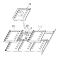
次に、横方向に並ぶ各縦桟12の前端部に横桟14を横方向に架け渡して載せ、各縦桟12の前端部において、横桟14の底板14aに係止金具15を配置し、縦桟12の主板12aの下面に補強部材16を配置し、ボルト17を係止金具15の底板15aの孔、横桟14の底板14aの孔、縦桟12の主板12aの孔を通じて補強部材16のネジ孔にねじ込んで締め付け、縦桟12の前端部に横桟14及び係止金具15を固定する。また、横方向に並ぶ各縦桟12の列毎に、横桟14を横方向に架け渡して固定する。これにより、複数本の横桟14が横方向に沿って長く配置されかつ縦方向に並設される。
Next, the
図10は、係止金具15を示す斜視図である。図10に示すように係止金具15は、底板15a、底板15aの両側を垂直に折り曲げてなる各側壁15b、及び底板15aの一辺を垂直に折り曲げてなる立設板15cを有している。底板15aには、孔15dが形成されており、この孔15dにボルト17が通される。各側壁15bの上端には、外側に折り曲げられた各受け部材15eが形成されている。立設板15cの上端には、底板15a側に折り曲げられた第1留め部15fと、底板15aとは反対側に折り曲げられた第2留め部15gが形成されている。2つの第1留め部15fが立設板15cの上端両側に設けられ、また1つの第2留め部15gが立設板15cの上端中央に設けられ、2つの第1留め部15fと1つの第2留め部15gが交互に配置されている。
FIG. 10 is a perspective view showing the locking
図6〜図9においては、係止金具15の各第1留め部15fが水流れ方向Aとは逆の上方向に向き、また係止金具15の第2留め部15gが水流れ方向Aに向いている。
6-9, each
図6に示すように太陽電池モジュール11は、2本の横桟14に架け渡され、水流れ方向Aの低い側に配置された横桟14(以下、下段の横桟14と称す)上の係止金具15の立設板15cと水流れ方向Aの高い側に配置された横桟14(以下、上段の横桟14と称す)の壁部14b間に挟み込まれる。また、太陽電池モジュール11の前端部が下段の横桟14上の係止金具15の各受け部材15eに載せられ、太陽電池モジュール11の後端部が上段の横桟14の台座部14cに載せられる。この状態で、太陽電池モジュール11の枠部材の前端が下段の横桟14上の係止金具15の各第1留め部15fに係合し、また太陽電池モジュール11の枠部材の後端の一部が上段の横桟14の壁部14bを越えて係止金具15の第2留め部15gに係合し、これにより太陽電池モジュール11が傾斜した状態で支持固定される。
As shown in FIG. 6, the
尚、1枚の太陽電池モジュール11毎に、太陽電池モジュール11の枠部材の前端に係合する2個の係止金具15と、その後端に係合する2個の係止金具15とを必要とし、合計4個の係止金具15を必要とする。従って、太陽電池モジュール11の設置枚数の4倍個数の係止金具15を各横桟14に分けて配置する必要がある。
Each
また、下段の横桟14上の係止金具15の立設板15cと上段の横桟14の壁部14bとの間に、太陽電池モジュール11を配して固定することから、下段の横桟14上の係止金具15の立設板15cと上段の横桟14の壁部14bとの間隔を太陽電池モジュール11の水流れ方向Aの幅と同じか僅かに広くする必要があり、そのような間隔を設定するには、各縦桟11の水流れ方向Aの配置間隔を適宜に設定する必要がある。このため、先に述べたように屋根4上に各支持金具1を配置して固定する最初の作業のときに、まず太陽電池モジュール11の水流れ方向Aの幅に応じて各縦桟11の水流れ方向Aの配置間隔を決め、更に各縦桟11に対する各支持金具1の取付け位置を決めて、各支持金具1の取付け位置に応じて屋根4上の各支持金具1の配置間隔及び位置を決める必要がある。
Further, since the
このような太陽光発電システムでは、第1実施形態の取付け構造を適用していることから、金属製瓦5を取外す必用がなく、施工作業が簡単である。また、Oリング7によりドリルネジ2の頭部2aと金属製瓦5の表面との間を止水して、ドリルネジ2により形成された金属製瓦5の孔からの雨水の浸入を防止することができる。更に、支持金具1にかかった太陽電池モジュール11の荷重は、ドリルネジ2にかかって、野地板6で受けられ、金属製瓦5には殆どかからず、金属製瓦5が変形することはなく、金属製瓦5の変形を原因とする雨漏りが生じることはない。
In such a solar power generation system, since the mounting structure of the first embodiment is applied, it is not necessary to remove the
ところで、第1実施形態では、支持金具1を金属製瓦に取付けているが、支持金具1を粘土、セメント、セラミック等からなる瓦に取付けることも可能である。この場合は、ドリルネジ2を通す孔を瓦に形成し、ドリルネジ2を瓦の孔に通して野地板にねじ込んで固定し、各ボルト3を支持金具1の底板1bの各孔1aを通じて各ドリルネジ2の頭部2aの雌ネジ2bにねじ込んで、支持金具1を取付けて固定する。
By the way, in 1st Embodiment, although the
しかしながら、粘土、セメント、セラミック等からなる瓦の場合は、瓦同士を重ね合わせた継ぎ目の隙間より雨水が浸入することから、ルーフィングシートを野地板に重ねているものの、ドリルネジ2を野地板にねじ込むと、ルーフィングシートに孔が開くので、この孔が雨漏りの原因となり得る。
However, in the case of tiles made of clay, cement, ceramic, etc., rainwater invades through the gap between the seams where the tiles are overlapped, so the roofing sheet is superimposed on the field plate, but the
そこで、ルーフィングシートの孔からの雨漏りを防止するべく、次のような施工手順で支持金具1を設置する。ここでは、まず、図11に示すように支持金具1の各第1孔1aに重なるそれぞれの穿孔21aを粘土、セメント、セラミック等からなる瓦21に形成する。穿孔21aの径は、ドリルネジ2の外径よりも僅かに大きい程度が好ましく、例えば5mm程度である。
Then, in order to prevent the rain leak from the hole of a roofing sheet, the
そして、図12(a)に示すように瓦21の各穿孔21a及び/又は各穿孔21aの周縁に硬化前のシーリング材(止水部材)22を塊状に盛り付けたり、各穿孔21aに硬化前のシーリング材22を充填したりする。このシーリング材22は、例えば建築用のものがよく、アクリル系、シリコン系、ウレタン系等のいずれでもよい。また、シーリング材22は、その硬化前に、瓦21の穿孔21a及び/又は穿孔21aの周縁に盛り付けられたり充填されたりした塊がその自重により穿孔21aから自然落下してしまわない程度の粘性を有するものとする。このようなシーリング材22の粘性は、穿孔21aの大きさや使用温度等の条件によって変わるため、そのような条件に応じてシーリング材22の種類等を適宜選択するのが好ましい。
Then, as shown in FIG. 12 (a), the
この後、ドリルネジ2を瓦21の穿孔21aに通し、各ドリルネジ2を回転させながらルーフィングシート23を介して野地板6にねじ込んで固定する。このとき、図12(b)に示すように穿孔21aに盛り付けられたり充填されたりしたシーリング材22がドリルネジ2の先端及び外周に付着し、引き続いてドリルネジ2の先端がルーフィングシート23を介して野地板6にねじ込まれて固定されるときには、図12(c)に示すようにドリルネジ2の先端及び外周に付着したシーリング材22がルーフィングシート23の表面で止められてドリルネジ2の外周に環状に溜まり、この環状に溜まったシーリング材22によりルーフィングシート23の孔が止水される。また、瓦21の穿孔21aや穿孔21aの周囲にはシーリング材22の一部が残り、この残ったシーリング材22により瓦21の穿孔21aが止水される。
Thereafter, the drill screws 2 are passed through the
すなわち、瓦21の穿孔21aや穿孔21aの周囲に残ったシーリング材22が瓦21の穿孔21aを止水する第1止水部材となる。また、ドリルネジ2の先端及び外周に付着したシーリング材22がルーフィングシート23の孔を止水する第2止水部材となる。このシーリング材22の硬化後は、瓦21の穿孔21aの止水状態及びルーフィングシート23の孔の止水状態が安定的に維持される。このため、瓦21の穿孔21aから雨水が浸入することはなく、また瓦21同士を重ね合わせた隙間から雨水が浸入しても、ルーフィングシート23に形成された孔が雨漏りの原因になることはない。
That is, the
尚、図13に示すようにドリルネジ2を傾斜した野地板6に対して垂直にねじ込むため、シーリング材22を瓦21の穿孔21aから垂らしても、シーリング材22の落下箇所がドリルネジ2のねじ込み箇所から外れてしまい、シーリング材22によりルーフィングシート23の孔を止水することはできない。
Since the
この後、図12(c)に示すように支持金具1の底板1bを各ドリルネジ2の頭部2aに載せて、各ボルト3を底板1bの各孔1aを通じて各ドリルネジ2の頭部2aの雌ネジ2bにねじ込んで、支持金具1を各ドリルネジ2の頭部2aに固定する。
Thereafter, as shown in FIG. 12 (c), the
このように瓦21に各穿孔21aを形成し、各穿孔21a及び/又は各穿孔21aの周縁に硬化前のシーリング材22を塊状に盛り付けたり、各穿孔21aに硬化前のシーリング材22を充填したりしてから、ドリルネジ2を瓦21の穿孔21aに通し、ルーフィングシート23を介して野地板6にねじ込んで固定しているので、シーリング材22がドリルネジ2の先端に付着して下降して行きルーフィングシート23の表面で止められてドリルネジ2の外周に環状に溜まり、シーリング材22がルーフィングシート23の孔を止水する第2止水部材となって、ルーフィングシート23の孔が止水される。また、瓦21の穿孔21aに残ったシーリング材22の一部が第1止水部材となって、瓦21の穿孔21aが止水される。
In this way, the
また、瓦21を取外す必用がなく、支持金具1を金属製瓦に取付ける場合と同様に、施工作業が簡単である。また、支持金具1にかかった荷重は、ドリルネジ2にかかって支持され、野地板6で受けられ、瓦21には殆どかからず、瓦21の位置ズレ等が生じることはなく、瓦21の位置ズレを原因とする雨漏りが生じることはない。更に、Oリング7を省略することができる。
Further, it is not necessary to remove the
更に、このような施工手順は、粘土、セメント、セラミック等からなる瓦だけではなく、金属製瓦にも適用可能である。 Furthermore, such a construction procedure can be applied not only to tiles made of clay, cement, ceramic, but also to metal roof tiles.
次に、本発明の支持部材の取付け構造の第2実施形態を説明する。図14は、第2実施形態の取付け構造を側面から見て示す断面図である。尚、図14において、図1〜図3と同様の作用を果たす部位には同じ符号を付す。 Next, a second embodiment of the support member mounting structure of the present invention will be described. FIG. 14 is a cross-sectional view showing the mounting structure of the second embodiment as viewed from the side. In FIG. 14, the same reference numerals are given to portions that perform the same operations as in FIGS. 1 to 3.
図14に示すように第2実施形態の取付け構造では、支持金具(支持部材)1と、3本の螺子部材31と、支持金具1を各螺子部材31に取付ける3組の受けナット(受け部材)32及び締結用ナット(固定部材)33とを備えており、各螺子部材31を屋根4の金属製瓦5に刺し通して野地板6にねじ込んで固定し、各螺子部材31にそれぞれの受けナット32をねじ込んで、支持金具1の底板1bの各孔1aを各螺子部材31に通し、各螺子部材31にそれぞれの締結用ナット33をねじ込んで、支持金具1を取付け固定している。
As shown in FIG. 14, in the mounting structure of the second embodiment, a support fitting (support member) 1, three
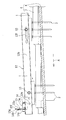
図15は、螺子部材31を示す側面図である。図15に示すように螺子部材31は、棒状のものであり、その下端側には野地板6にねじ込むのに適したドリルネジと同じ形状の螺子溝31aが形成され、また上端側外周にはナットをねじ込むのに適したボルトと同じ形状の螺子溝31bが形成されている。この螺子部材31は、その上端部を電動ドリルの先端に取付けられた全ねじソケット34に差し込まれて係合され、電動ドリルにより全ねじソケット34と共に回転させられて、野地板6にねじ込まれる。
FIG. 15 is a side view showing the
このような第2実施形態の取付け構造の施工手順は、次の通りである。まず、3本の棒状の螺子部材31を支持金具1の各孔1aと同一間隔で位置決めして、電動ドリルの先端に取付けられた全ねじソケット34を用いて、各螺子部材31を金属製瓦5に貫通させ、更に各螺子部材31を野地板6にねじ込んで固定する。
The construction procedure of the mounting structure of the second embodiment is as follows. First, three rod-shaped
この後、各Oリング(止水部材)7を各螺子部材31に嵌め入れ、各ネジ部材31の上端から各受けナット32をねじ込んで、各受けナット32を各ネジ部材31の胴部に配する。このとき、金属製瓦5が変形せずかつ受けナット32と金属製瓦5表面との間にOリング7がはさみ込まれて押し潰されるように受けナット32の締結力を調節し、Oリング7により受けナット32と金属製瓦5の表面との間を止水する。
Thereafter, each O-ring (water-stop member) 7 is fitted into each
引き続いて、支持金具1の底板1bの各孔1aを各螺子部材31に通し、各螺子部材31にそれぞれの締結用ナット33をねじ込んで、各受けナット32と各締結用ナット33の間に支持金具1を挟み込んで固定する。
Subsequently, the
このような施工手順では、金属製瓦5を取外す必用がなく、部品点数が少ないため、施工作業が簡単である。また、Oリング7は、押し潰されることにより受けナット32と金属製瓦5の表面との間を止水して、螺子部材31により形成された金属製瓦5の孔からの雨水の浸入を防ぐ。更に、支持金具1の荷重及び支持金具1により支持される構造物(図示せず)の荷重は、各螺子部材31に直接かかって、各螺子部材31を通じて野地板6で受けられ、金属製瓦5に殆ど作用しない。このため、支持金具1の荷重及び構造物の荷重により金属製瓦5が変形することはなく、金属製瓦5の変形を原因とする雨漏りが生じることはない。
In such a construction procedure, it is not necessary to remove the
次に、本発明の支持部材の取付け構造の第3実施形態を説明する。図16は、第3実施形態の取付け構造を側面から見て示す断面図である。また、図17は、第3実施形態の取付け構造を示す分解斜視図である。尚、図16、図17において、図1〜図3と同様の作用を果たす部位には同じ符号を付す。 Next, a third embodiment of the support member mounting structure of the present invention will be described. FIG. 16 is a cross-sectional view showing the mounting structure of the third embodiment as viewed from the side. FIG. 17 is an exploded perspective view showing the mounting structure of the third embodiment. In FIGS. 16 and 17, the same reference numerals are given to portions that perform the same functions as those in FIGS. 1 to 3.
図16、図17に示すように第3実施形態の取付け構造では、支持金具(支持部材)1Aと、3本のドリルネジ(螺子部材)41と、取付け板(固定部材)42と、2本のボルト(固定部材)43とを備えており、各ドリルネジ41を取付け板42の各孔42aを介して屋根4の金属製瓦5に刺し通し野地板6にねじ込んで、各ドリルネジ41及び取付け板42を固定し、支持金具1Aを各ドリルネジ41の頭部(受け部材)41aに載せて当接させ、各ボルト43を支持金具1Aの両端の各孔1eを通じて取付け板42の両端の各ネジ孔42bにねじ込んで、支持金具1を固定している。
As shown in FIGS. 16 and 17, in the mounting structure of the third embodiment, a support fitting (support member) 1A, three drill screws (screw members) 41, a mounting plate (fixing member) 42, and two Bolts (fixing members) 43 are provided. The drill screws 41 are inserted into the
このような第3実施形態の取付け構造の施工手順は、次の通りである。まず、金属製瓦5の表面における支持金具1Aの配置領域にシーリング材(止水部材)44を設け、このシーリング材44に取付け板42を重ねて配し、各ドリルネジ41を取付け板42の各孔42aを介して屋根4の金属製瓦5に刺し通し野地板6にねじ込み、各ドリルネジ41及び取付け板42を固定する。このとき、各ドリルネジ41の締め込みにより取付け板42がシーリング材44に圧接され、シーリング材44が押し潰されて広がって延び、金属製瓦5と取付け板42の間が広い範囲で止水され、各ドリルネジ41により形成された金属製瓦5の各孔も止水される。
The construction procedure of the mounting structure of the third embodiment is as follows. First, a sealing material (water-stop member) 44 is provided in a region where the
この後、支持金具1Aの底板1bを各ドリルネジ41の頭部41aに載せて当接させ、各ボルト43を支持金具1Aの両端の各孔1eを通じて取付け板42の両端の各ネジ孔42bにねじ込んで、支持金具1を固定する。
Thereafter, the
このような施工手順では、金属製瓦5を取外す必用がなく、部品点数が少ないため、施工作業が簡単である。また、シーリング材44は、押し潰されることにより金属製瓦5と取付け板42の間の広い範囲を止水して、ドリルネジ41により形成された金属製瓦5の孔からの雨水の浸入を防ぐ。更に、支持金具1Aの底板1bを各ドリルネジ41の頭部41aに当接させていることから、支持金具1Aの荷重及び支持金具1Aにより支持される構造物(図示せず)の荷重は、各ドリルネジ41の頭部41aに直接かかって、各ドリルネジ41を通じて野地板6で受けられることになり、金属製瓦5に殆ど作用しない。このため、支持金具1Aの荷重及び構造物の荷重により金属製瓦5が変形することはなく、金属製瓦5の変形を原因とする雨漏りが生じることはない。
In such a construction procedure, it is not necessary to remove the
次に、本発明の支持部材の取付け構造の第4実施形態を説明する。図18は、第4実施形態の取付け構造を側面から見て示す断面図である。 Next, a fourth embodiment of the support member mounting structure of the present invention will be described. FIG. 18 is a cross-sectional view showing the mounting structure of the fourth embodiment as viewed from the side.
図18に示すように第4実施形態の取付け構造では、金属製瓦5の表面における支持金具(支持部材)1Bの配置領域にシーリング材(止水部材)44を設け、このシーリング材44に支持金具1Bを重ねて配し、各ドリルネジ(螺子部材)41を支持金具1Bの底板1bの各孔を介して屋根4の金属製瓦5に刺し通し野地板6にねじ込み、各ドリルネジ41及び支持金具1Bを固定する。このとき、各ドリルネジ41の締め込みにより支持金具1Bがシーリング材44に圧接され、シーリング材44が押し潰されて広がって延び、金属製瓦5と支持金具1Bの間が広い範囲で止水されるようにする。
As shown in FIG. 18, in the mounting structure of the fourth embodiment, a sealing material (water-stopping member) 44 is provided in the arrangement region of the support metal fitting (supporting member) 1 </ b> B on the surface of the
この後、取付け板(固定部材)45を各ドリルネジ41の頭部(受け部材)41aに載せて当接させ、各ボルト(固定部材)43を取付け板45の両端の各孔を通じて支持金具1Bの両端の各ネジ孔にねじ込んで、取付け板45を固定する。
Thereafter, the mounting plate (fixing member) 45 is placed on and contacted with the head (receiving member) 41a of each
このような第4実施形態においても、金属製瓦5を取外す必用がなく、部品点数が少ないため、施工作業が簡単である。また、シーリング材44は、押し潰されることにより金属製瓦5と支持金具1Bの間の広い範囲を止水して、ドリルネジ41により形成された金属製瓦5の孔からの雨水の浸入を防ぐ。更に、取付け板45を各ドリルネジ41の頭部41aに載せて当接させ、各ボルト43により支持金具1Bの両端と取付け板45の両端とを締結していることから、支持金具1Bの荷重及び支持金具1Bにより支持される構造物の荷重は、各ドリルネジ41の頭部41aに直接かかって、各ドリルネジ41を通じて野地板6で受けられることになり、金属製瓦5に殆ど作用しない。
In the fourth embodiment as described above, it is not necessary to remove the
以上、添付図面を参照しながら本発明の好適な実施形態について説明したが、本発明は、その精神または主要な特徴から逸脱することなく、他のいろいろな形で実施することができる。そのため、上述の実施例はあらゆる点で単なる例示にすぎず、限定的に解釈してはならない。本発明の範囲は特許請求の範囲によって示すものであって、明細書本文には、なんら拘束されない。さらに、特許請求の範囲の均等範囲に属する変形や変更は、全て本発明の範囲内のものである。 Although the preferred embodiments of the present invention have been described above with reference to the accompanying drawings, the present invention can be implemented in various other forms without departing from the spirit or main features thereof. For this reason, the above-described embodiment is merely an example in all respects and should not be interpreted in a limited manner. The scope of the present invention is indicated by the claims, and is not restricted by the text of the specification. Further, all modifications and changes belonging to the equivalent scope of the claims are within the scope of the present invention.
例えば、本発明の支持部材の取付け構造を適用して、太陽電池モジュールの代わりに、太陽熱発電に用いられる反射鏡パネル等を支持してもよい。これにより、太陽熱発電システムを構築することができる。また、屋根だけではなく、垂直な壁面等にも、本発明を適用することができる。 For example, the support member mounting structure of the present invention may be applied to support a reflector panel or the like used for solar thermal power generation instead of the solar cell module. Thereby, a solar thermal power generation system can be constructed. Further, the present invention can be applied not only to a roof but also to a vertical wall surface.
1、1A、1B 支持金具(支持部材)
2、41 ドリルネジ(螺子部材)
2a、41a 頭部(受け部材)
3 ボルト(固定部材)
4 屋根
5 金属製瓦
6 野地板
7 Oリング(止水部材)
11 太陽電池モジュール(構造物)
12 縦桟
13、17 ボルト
14 横桟
15 係止金具
16 補強部材
21 瓦
22、44 シーリング材(止水部材)
23 ルーフィングシート
31 螺子部材
32 受けナット(受け部材)
33 締結用ナット(固定部材)
34 全ねじソケット
42、45 取付け板(固定部材)
43 ボルト(固定部材)
1, 1A, 1B Support bracket (support member)
2, 41 Drill screw (screw member)
2a, 41a Head (receiving member)
3 Bolt (fixing member)
4
11 Solar cell module (structure)
12
23
33 Fastening nut (fixing member)
34 Fully threaded
43 Bolt (fixing member)
Claims (10)
前記被設置物にねじ込まれた螺子部材と、
前記螺子部材に設けられた受け部材と、
前記構造物を支持する支持部材と、
前記支持部材を前記螺子部材に対して固定する固定部材とを備え、
前記支持部材もしくは前記固定部材の少なくとも一方が前記受け部材に載置されて固定されていることを特徴とする支持部材の取付け構造。 A support member mounting structure for supporting a structure on an installation object,
A screw member screwed into the object to be installed;
A receiving member provided on the screw member;
A support member for supporting the structure;
A fixing member for fixing the support member to the screw member,
At least one of the support member or the fixing member is placed and fixed on the receiving member.
前記被設置物上には被覆部材が設けられており、
前記受け部材もしくは前記支持部材もしくは前記固定部材の少なくともいずれかが前記被覆部材に少なくとも止水部材を介して接していることを特徴とする支持部材の取付け構造。 The support member mounting structure according to claim 1,
A covering member is provided on the object to be installed,
At least one of the receiving member, the support member, or the fixing member is in contact with the covering member via at least a water stop member.
前記被設置物にねじ込まれた螺子部材と、
前記被設置物と螺子部材とに粘着した止水部材と、
前記螺子部材に設けられた受け部材と、
前記構造物を支持する支持部材と、
前記支持部材を前記螺子部材に対して固定する固定部材とを備え、
前記支持部材もしくは前記固定部材の少なくとも一方が前記受け部材に載置されて固定されていることを特徴とする支持部材の取付け構造。 A support member mounting structure for supporting a structure on an installation object,
A screw member screwed into the object to be installed;
A water stop member adhered to the object to be installed and the screw member;
A receiving member provided on the screw member;
A support member for supporting the structure;
A fixing member for fixing the support member to the screw member,
At least one of the support member or the fixing member is placed and fixed on the receiving member.
前記受け部材は、前記螺子部材の頭であり、
前記螺子部材の頭には雌ネジが形成され、
前記固定部材は前記雌ネジとかみ合う雄ネジであり、
前記支持部材は前記ネジ部材の頭に載置され前記雄ネジで固定されることを特徴とする支持部材の取付け構造。 A mounting structure for a support member according to claim 1 or 3,
The receiving member is a head of the screw member;
A female screw is formed on the head of the screw member,
The fixing member is a male screw that meshes with the female screw,
The support member mounting structure, wherein the support member is placed on a head of the screw member and fixed by the male screw.
前記受け部材は前記螺子部材の軸を囲むように設けられ、
前記支持部材は前記受け部材に載置され前記固定部材と前記受け部材により狭持され固定されていることを特徴とする支持部材の取付け構造。 A mounting structure for a support member according to claim 1 or 3,
The receiving member is provided so as to surround the shaft of the screw member,
The support member mounting structure, wherein the support member is placed on the receiving member and is nipped and fixed by the fixing member and the receiving member.
前記受け部材は前記螺子部材の頭であり、
前記支持部材は前記螺子部材の頭に載置され、
前記固定部材は、前記支持部材と対を成して前記螺子部材の頭を狭持する部材であることを特徴とする支持部材の取付け構造。 A mounting structure for a support member according to claim 1 or 3,
The receiving member is a head of the screw member;
The support member is placed on the head of the screw member,
The mounting structure of the support member, wherein the fixing member is a member that forms a pair with the support member and holds the head of the screw member.
前記受け部材は前記螺子部材の頭であり、
前記支持部材は前記螺子部材の頭の下部に配置され、
前記固定部材は前記螺子部材の頭に載置され、前記支持部材と対を成して前記螺子部材の頭を狭持する部材であることを特徴とする支持部材の取付け構造。 A mounting structure for a support member according to claim 1 or 3,
The receiving member is a head of the screw member;
The support member is disposed under the head of the screw member,
The mounting structure for a support member, wherein the fixing member is a member that is placed on the head of the screw member and that forms a pair with the support member to hold the head of the screw member.
螺子部材を前記被覆部材に貫通させ、
前記螺子部材を被設置物にねじ込み、
前記螺子部材に設けられた荷重受け部材に構造物を支持する支持部材を載置し、
固定部材を用いて前記支持部材を固定することを特徴とする支持構造の施工方法。 A construction method of a support structure for supporting a structure on an installation object provided with a covering member,
A screw member is passed through the covering member;
Screw the screw member into the object to be installed,
A support member that supports a structure is placed on a load receiving member provided on the screw member,
A method for constructing a support structure, wherein the support member is fixed using a fixing member.
前記被覆部材に孔をあけ、
前記孔及び/又は孔周縁に粘性を有する樹脂を充填し、
螺子部材を前記孔に貫通させ、
前記螺子部材を被設置物にねじ込み、
前記螺子部材に設けられた荷重受け部材に構造物を支持する支持部材を載置し、
固定部材を用いて前記支持部材を固定することを特徴とする支持構造の施工方法。 A construction method of a support structure for supporting a structure on an installation object provided with a covering member,
A hole is made in the covering member,
Filling the hole and / or hole periphery with a viscous resin;
A screw member is passed through the hole,
Screw the screw member into the object to be installed,
A support member that supports a structure is placed on a load receiving member provided on the screw member,
A method for constructing a support structure, wherein the support member is fixed using a fixing member.
Priority Applications (1)
| Application Number | Priority Date | Filing Date | Title |
|---|---|---|---|
| JP2012084117A JP2013213350A (en) | 2012-04-02 | 2012-04-02 | Supporting member attachment structure, construction method for support structure, and photovoltaic power generation system using supporting member attachment structure |
Applications Claiming Priority (1)
| Application Number | Priority Date | Filing Date | Title |
|---|---|---|---|
| JP2012084117A JP2013213350A (en) | 2012-04-02 | 2012-04-02 | Supporting member attachment structure, construction method for support structure, and photovoltaic power generation system using supporting member attachment structure |
Publications (2)
| Publication Number | Publication Date |
|---|---|
| JP2013213350A true JP2013213350A (en) | 2013-10-17 |
| JP2013213350A5 JP2013213350A5 (en) | 2015-05-21 |
Family
ID=49586864
Family Applications (1)
| Application Number | Title | Priority Date | Filing Date |
|---|---|---|---|
| JP2012084117A Pending JP2013213350A (en) | 2012-04-02 | 2012-04-02 | Supporting member attachment structure, construction method for support structure, and photovoltaic power generation system using supporting member attachment structure |
Country Status (1)
| Country | Link |
|---|---|
| JP (1) | JP2013213350A (en) |
Cited By (7)
| Publication number | Priority date | Publication date | Assignee | Title |
|---|---|---|---|---|
| JP2014077317A (en) * | 2012-10-12 | 2014-05-01 | Kmew Co Ltd | Structure for installing functional member in roof |
| JP2016051087A (en) * | 2014-08-29 | 2016-04-11 | 日本電産コパル株式会社 | Imaging device |
| JPWO2015016244A1 (en) * | 2013-07-30 | 2017-03-02 | 京セラ株式会社 | Solar cell device |
| JP2018155054A (en) * | 2017-03-21 | 2018-10-04 | 株式会社屋根技術研究所 | Fitting structure and fitting device for roof-top installation |
| JP2020023826A (en) * | 2018-08-07 | 2020-02-13 | 株式会社竹中工務店 | Extension method of facility stand |
| JP2020084559A (en) * | 2018-11-26 | 2020-06-04 | 株式会社屋根技術研究所 | Fitting structure for on-roof installed object and trestle for on-roof installed object |
| KR20210094217A (en) * | 2020-01-21 | 2021-07-29 | 이정훈 | The solar panel support module |
Citations (3)
| Publication number | Priority date | Publication date | Assignee | Title |
|---|---|---|---|---|
| JPH0488512U (en) * | 1990-12-13 | 1992-07-31 | ||
| JP2005315018A (en) * | 2004-04-30 | 2005-11-10 | Sekisui House Ltd | Rack mounting structure for placing article on roof, rack mounting metal piece and rack mounting method |
| JP2011122406A (en) * | 2009-12-14 | 2011-06-23 | Tsuruya:Kk | After-fitted on-roof installation object fixing tile, and screw used for the same |
-
2012
- 2012-04-02 JP JP2012084117A patent/JP2013213350A/en active Pending
Patent Citations (3)
| Publication number | Priority date | Publication date | Assignee | Title |
|---|---|---|---|---|
| JPH0488512U (en) * | 1990-12-13 | 1992-07-31 | ||
| JP2005315018A (en) * | 2004-04-30 | 2005-11-10 | Sekisui House Ltd | Rack mounting structure for placing article on roof, rack mounting metal piece and rack mounting method |
| JP2011122406A (en) * | 2009-12-14 | 2011-06-23 | Tsuruya:Kk | After-fitted on-roof installation object fixing tile, and screw used for the same |
Cited By (11)
| Publication number | Priority date | Publication date | Assignee | Title |
|---|---|---|---|---|
| JP2014077317A (en) * | 2012-10-12 | 2014-05-01 | Kmew Co Ltd | Structure for installing functional member in roof |
| JPWO2015016244A1 (en) * | 2013-07-30 | 2017-03-02 | 京セラ株式会社 | Solar cell device |
| JP2017223108A (en) * | 2013-07-30 | 2017-12-21 | 京セラ株式会社 | Solar cell device |
| JP2016051087A (en) * | 2014-08-29 | 2016-04-11 | 日本電産コパル株式会社 | Imaging device |
| JP2018155054A (en) * | 2017-03-21 | 2018-10-04 | 株式会社屋根技術研究所 | Fitting structure and fitting device for roof-top installation |
| JP2020023826A (en) * | 2018-08-07 | 2020-02-13 | 株式会社竹中工務店 | Extension method of facility stand |
| JP7049961B2 (en) | 2018-08-07 | 2022-04-07 | 株式会社竹中工務店 | How to add equipment mount |
| JP2020084559A (en) * | 2018-11-26 | 2020-06-04 | 株式会社屋根技術研究所 | Fitting structure for on-roof installed object and trestle for on-roof installed object |
| JP7017243B2 (en) | 2018-11-26 | 2022-02-08 | 株式会社屋根技術研究所 | Mounting structure for rooftop installations |
| KR20210094217A (en) * | 2020-01-21 | 2021-07-29 | 이정훈 | The solar panel support module |
| KR102353512B1 (en) | 2020-01-21 | 2022-01-19 | 이정훈 | The solar panel support module |
Similar Documents
| Publication | Publication Date | Title |
|---|---|---|
| JP2013213350A (en) | Supporting member attachment structure, construction method for support structure, and photovoltaic power generation system using supporting member attachment structure | |
| US10236821B1 (en) | Mounting apparatus to secure solar panel rails to S-tile roofs | |
| WO2010131386A1 (en) | Solar module fixing structure | |
| JP2013040462A (en) | Structure for mounting photovoltaic power generation system | |
| JP5689178B2 (en) | Installation member mounting structure, installation member mounting apparatus, installation member mounting structure construction method, and photovoltaic power generation system using the installation member mounting structure | |
| JPH10122125A (en) | Fitting frame for solar energy utilization facility | |
| JP2017025569A (en) | Photovoltaic power generation device | |
| JP2014043720A (en) | Solar energy utilizing facility mounting rack and photovoltaic power generation apparatus | |
| JP2007205058A (en) | Solar-cell module, and structure for mounting solar-cell module to folded-plate roof | |
| JP2011208361A (en) | Base installation structure of roof | |
| JP5976339B2 (en) | Mounting device and mounting method for rooftop equipment installation stand | |
| JP2008280839A (en) | Mounting structure and mounting method of solar cell | |
| JP3194299U (en) | Support panel for solar panel | |
| JP2007285042A (en) | Mounting structure of solar-cell panel | |
| JP2013118238A (en) | Support cradle structure for photovoltaic power generation panel frame and support metal fitting | |
| JP6577169B2 (en) | Mounting structure of solar panel mount and construction method of solar panel mount | |
| JP2015055108A (en) | Panel installation structure | |
| JP5725499B2 (en) | Mounting member, photovoltaic power generation system and mounting method | |
| JP2014043729A (en) | Mounting structure for installation object, and mounting method | |
| JP5714873B2 (en) | Mounting member | |
| JP2012144939A (en) | Attachment structure of solar cell module to roof | |
| WO2017138251A1 (en) | Affixation fitting and photovoltaic power generation device | |
| JP6968559B2 (en) | Stand for solar cell module and photovoltaic power generation device | |
| JP5968115B2 (en) | Equipment fixing device | |
| CN219604577U (en) | Photovoltaic heat preservation integrated plate and photovoltaic heat preservation system |
Legal Events
| Date | Code | Title | Description |
|---|---|---|---|
| A521 | Written amendment |
Free format text: JAPANESE INTERMEDIATE CODE: A523 Effective date: 20150327 |
|
| A621 | Written request for application examination |
Free format text: JAPANESE INTERMEDIATE CODE: A621 Effective date: 20150327 |
|
| A977 | Report on retrieval |
Free format text: JAPANESE INTERMEDIATE CODE: A971007 Effective date: 20151217 |
|
| A131 | Notification of reasons for refusal |
Free format text: JAPANESE INTERMEDIATE CODE: A131 Effective date: 20160105 |
|
| A02 | Decision of refusal |
Free format text: JAPANESE INTERMEDIATE CODE: A02 Effective date: 20160510 |