JP2013207298A - Laser device, laser system and extreme-ultraviolet light generation device - Google Patents
Laser device, laser system and extreme-ultraviolet light generation device Download PDFInfo
- Publication number
- JP2013207298A JP2013207298A JP2013001704A JP2013001704A JP2013207298A JP 2013207298 A JP2013207298 A JP 2013207298A JP 2013001704 A JP2013001704 A JP 2013001704A JP 2013001704 A JP2013001704 A JP 2013001704A JP 2013207298 A JP2013207298 A JP 2013207298A
- Authority
- JP
- Japan
- Prior art keywords
- amplifier
- laser
- light
- gas
- gain
- Prior art date
- Legal status (The legal status is an assumption and is not a legal conclusion. Google has not performed a legal analysis and makes no representation as to the accuracy of the status listed.)
- Pending
Links
Images


Classifications
-
- H—ELECTRICITY
- H01—ELECTRIC ELEMENTS
- H01S—DEVICES USING THE PROCESS OF LIGHT AMPLIFICATION BY STIMULATED EMISSION OF RADIATION [LASER] TO AMPLIFY OR GENERATE LIGHT; DEVICES USING STIMULATED EMISSION OF ELECTROMAGNETIC RADIATION IN WAVE RANGES OTHER THAN OPTICAL
- H01S3/00—Lasers, i.e. devices using stimulated emission of electromagnetic radiation in the infrared, visible or ultraviolet wave range
- H01S3/10—Controlling the intensity, frequency, phase, polarisation or direction of the emitted radiation, e.g. switching, gating, modulating or demodulating
- H01S3/10007—Controlling the intensity, frequency, phase, polarisation or direction of the emitted radiation, e.g. switching, gating, modulating or demodulating in optical amplifiers
- H01S3/10015—Controlling the intensity, frequency, phase, polarisation or direction of the emitted radiation, e.g. switching, gating, modulating or demodulating in optical amplifiers by monitoring or controlling, e.g. attenuating, the input signal
-
- H—ELECTRICITY
- H01—ELECTRIC ELEMENTS
- H01S—DEVICES USING THE PROCESS OF LIGHT AMPLIFICATION BY STIMULATED EMISSION OF RADIATION [LASER] TO AMPLIFY OR GENERATE LIGHT; DEVICES USING STIMULATED EMISSION OF ELECTROMAGNETIC RADIATION IN WAVE RANGES OTHER THAN OPTICAL
- H01S3/00—Lasers, i.e. devices using stimulated emission of electromagnetic radiation in the infrared, visible or ultraviolet wave range
- H01S3/0014—Monitoring arrangements not otherwise provided for
-
- H—ELECTRICITY
- H05—ELECTRIC TECHNIQUES NOT OTHERWISE PROVIDED FOR
- H05G—X-RAY TECHNIQUE
- H05G2/00—Apparatus or processes specially adapted for producing X-rays, not involving X-ray tubes, e.g. involving generation of a plasma
- H05G2/001—X-ray radiation generated from plasma
- H05G2/008—X-ray radiation generated from plasma involving a beam of energy, e.g. laser or electron beam in the process of exciting the plasma
-
- H—ELECTRICITY
- H01—ELECTRIC ELEMENTS
- H01S—DEVICES USING THE PROCESS OF LIGHT AMPLIFICATION BY STIMULATED EMISSION OF RADIATION [LASER] TO AMPLIFY OR GENERATE LIGHT; DEVICES USING STIMULATED EMISSION OF ELECTROMAGNETIC RADIATION IN WAVE RANGES OTHER THAN OPTICAL
- H01S2301/00—Functional characteristics
- H01S2301/02—ASE (amplified spontaneous emission), noise; Reduction thereof
-
- H—ELECTRICITY
- H01—ELECTRIC ELEMENTS
- H01S—DEVICES USING THE PROCESS OF LIGHT AMPLIFICATION BY STIMULATED EMISSION OF RADIATION [LASER] TO AMPLIFY OR GENERATE LIGHT; DEVICES USING STIMULATED EMISSION OF ELECTROMAGNETIC RADIATION IN WAVE RANGES OTHER THAN OPTICAL
- H01S3/00—Lasers, i.e. devices using stimulated emission of electromagnetic radiation in the infrared, visible or ultraviolet wave range
- H01S3/09—Processes or apparatus for excitation, e.g. pumping
- H01S3/097—Processes or apparatus for excitation, e.g. pumping by gas discharge of a gas laser
- H01S3/0971—Processes or apparatus for excitation, e.g. pumping by gas discharge of a gas laser transversely excited
-
- H—ELECTRICITY
- H01—ELECTRIC ELEMENTS
- H01S—DEVICES USING THE PROCESS OF LIGHT AMPLIFICATION BY STIMULATED EMISSION OF RADIATION [LASER] TO AMPLIFY OR GENERATE LIGHT; DEVICES USING STIMULATED EMISSION OF ELECTROMAGNETIC RADIATION IN WAVE RANGES OTHER THAN OPTICAL
- H01S3/00—Lasers, i.e. devices using stimulated emission of electromagnetic radiation in the infrared, visible or ultraviolet wave range
- H01S3/10—Controlling the intensity, frequency, phase, polarisation or direction of the emitted radiation, e.g. switching, gating, modulating or demodulating
- H01S3/10069—Memorized or pre-programmed characteristics, e.g. look-up table [LUT]
-
- H—ELECTRICITY
- H01—ELECTRIC ELEMENTS
- H01S—DEVICES USING THE PROCESS OF LIGHT AMPLIFICATION BY STIMULATED EMISSION OF RADIATION [LASER] TO AMPLIFY OR GENERATE LIGHT; DEVICES USING STIMULATED EMISSION OF ELECTROMAGNETIC RADIATION IN WAVE RANGES OTHER THAN OPTICAL
- H01S3/00—Lasers, i.e. devices using stimulated emission of electromagnetic radiation in the infrared, visible or ultraviolet wave range
- H01S3/10—Controlling the intensity, frequency, phase, polarisation or direction of the emitted radiation, e.g. switching, gating, modulating or demodulating
- H01S3/102—Controlling the intensity, frequency, phase, polarisation or direction of the emitted radiation, e.g. switching, gating, modulating or demodulating by controlling the active medium, e.g. by controlling the processes or apparatus for excitation
- H01S3/104—Controlling the intensity, frequency, phase, polarisation or direction of the emitted radiation, e.g. switching, gating, modulating or demodulating by controlling the active medium, e.g. by controlling the processes or apparatus for excitation in gas lasers
-
- H—ELECTRICITY
- H01—ELECTRIC ELEMENTS
- H01S—DEVICES USING THE PROCESS OF LIGHT AMPLIFICATION BY STIMULATED EMISSION OF RADIATION [LASER] TO AMPLIFY OR GENERATE LIGHT; DEVICES USING STIMULATED EMISSION OF ELECTROMAGNETIC RADIATION IN WAVE RANGES OTHER THAN OPTICAL
- H01S3/00—Lasers, i.e. devices using stimulated emission of electromagnetic radiation in the infrared, visible or ultraviolet wave range
- H01S3/14—Lasers, i.e. devices using stimulated emission of electromagnetic radiation in the infrared, visible or ultraviolet wave range characterised by the material used as the active medium
- H01S3/22—Gases
- H01S3/223—Gases the active gas being polyatomic, i.e. containing two or more atoms
- H01S3/2232—Carbon dioxide (CO2) or monoxide [CO]
-
- H—ELECTRICITY
- H01—ELECTRIC ELEMENTS
- H01S—DEVICES USING THE PROCESS OF LIGHT AMPLIFICATION BY STIMULATED EMISSION OF RADIATION [LASER] TO AMPLIFY OR GENERATE LIGHT; DEVICES USING STIMULATED EMISSION OF ELECTROMAGNETIC RADIATION IN WAVE RANGES OTHER THAN OPTICAL
- H01S3/00—Lasers, i.e. devices using stimulated emission of electromagnetic radiation in the infrared, visible or ultraviolet wave range
- H01S3/23—Arrangements of two or more lasers not provided for in groups H01S3/02 - H01S3/22, e.g. tandem arrangements of separate active media
- H01S3/2308—Amplifier arrangements, e.g. MOPA
- H01S3/2316—Cascaded amplifiers
-
- H—ELECTRICITY
- H01—ELECTRIC ELEMENTS
- H01S—DEVICES USING THE PROCESS OF LIGHT AMPLIFICATION BY STIMULATED EMISSION OF RADIATION [LASER] TO AMPLIFY OR GENERATE LIGHT; DEVICES USING STIMULATED EMISSION OF ELECTROMAGNETIC RADIATION IN WAVE RANGES OTHER THAN OPTICAL
- H01S3/00—Lasers, i.e. devices using stimulated emission of electromagnetic radiation in the infrared, visible or ultraviolet wave range
- H01S3/23—Arrangements of two or more lasers not provided for in groups H01S3/02 - H01S3/22, e.g. tandem arrangements of separate active media
- H01S3/2308—Amplifier arrangements, e.g. MOPA
- H01S3/2325—Multi-pass amplifiers, e.g. regenerative amplifiers
Landscapes
- Physics & Mathematics (AREA)
- Electromagnetism (AREA)
- Optics & Photonics (AREA)
- Engineering & Computer Science (AREA)
- Plasma & Fusion (AREA)
- Lasers (AREA)
- X-Ray Techniques (AREA)
- Exposure Of Semiconductors, Excluding Electron Or Ion Beam Exposure (AREA)
- Exposure And Positioning Against Photoresist Photosensitive Materials (AREA)
Abstract
Description
本開示は、極端紫外(EUV)光を生成するために、レーザ光に照射されるターゲットを供給する装置に関する。さらに、本開示は、そのようなターゲット供給装置を用いて極端紫外(EUV)光を生成するための装置に関する。 The present disclosure relates to an apparatus for supplying a target that is irradiated with laser light to generate extreme ultraviolet (EUV) light. Furthermore, the present disclosure relates to an apparatus for generating extreme ultraviolet (EUV) light using such a target supply apparatus.
近年、半導体プロセスの微細化に伴って、半導体プロセスの光リソグラフィにおける転写パターンの微細化が急速に進展している。次世代においては、70nm〜45nmの微細加工、さらには32nm以下の微細加工の要求に応えるべく、波長13nm程度のEUV光を生成する極端紫外光生成装置と縮小投影反射光学系(reduced projection reflective optics)とを組み合わせた露光装置の開発が期待されている。 In recent years, along with miniaturization of semiconductor processes, miniaturization of transfer patterns in optical lithography of semiconductor processes has been rapidly progressing. In the next generation, in order to meet the demands of 70 nm to 45 nm microfabrication and further 32 nm or less microfabrication, an extreme ultraviolet light generation device that generates EUV light with a wavelength of about 13 nm and a reduced projection reflective optics (reduced projection reflective optics) ) Is expected to be developed.
極端紫外光生成装置としては、ターゲット物質にレーザビームを照射することによって生成されるプラズマを用いたLPP(Laser Produced Plasma)方式の装置と、放電によって生成されるプラズマを用いたDPP(Discharge Produced Plasma)方式の装置と、軌道放射光を用いたSR(Synchrotron Radiation)方式の装置と、の3種類の装置が提案されている。 As an extreme ultraviolet light generation device, an LPP (Laser Produced Plasma) system using plasma generated by irradiating a target material with a laser beam and a DPP (Discharge Produced Plasma) using plasma generated by discharge ) Type device and SR (Synchrotron Radiation) type device using orbital radiation light have been proposed.
レーザ装置は、
パルスレーザ光を出力するマスターオシレータと、
前記パルスレーザ光の光路上に配置された少なくとも1つの増幅器と、
前記増幅器の入射側と出力側のどちらか一方の前記光路に配置され、前記増幅器からの自励発振光のエネルギを検出するエネルギ検出器と、
前記増幅器のゲインを調節するゲイン調節部と、
前記マスターオシレータからパルスレーザ光が前記増幅器に入力されていない時の前記エネルギ検出器の検出結果に基づいて、前記ゲイン調節部を制御する制御部と、
を備えてもよい。
Laser equipment
A master oscillator that outputs pulsed laser light;
At least one amplifier disposed on the optical path of the pulsed laser light;
An energy detector that is disposed in the optical path on either the input side or the output side of the amplifier and detects energy of self-oscillation light from the amplifier;
A gain adjuster for adjusting the gain of the amplifier;
A control unit for controlling the gain adjustment unit based on a detection result of the energy detector when pulse laser light is not input to the amplifier from the master oscillator;
May be provided.
本開示のいくつかの実施形態を、単なる例として、添付の図面を参照して以下に説明する。
<内容>
1.概要
2.用語の説明
3.極端紫外光生成装置の全体説明
3.1 構成
3.2 動作
4.増幅器を含むレーザ装置
4.1 構成
4.2 動作
4.3 作用
5.モニタを含む増幅器
5.1 構成
5.2 動作
5.3 作用
5.4 その他
6.ガス調節部を含む増幅器
6.1 構成
6.2 動作
6.3 作用
6.4 その他
<Contents>
1.
以下、本開示の実施形態について、図面を参照しながら詳しく説明する。以下に説明される実施形態は、本開示のいくつかの例を示すものであって、本開示の内容を限定するものではない。また、各実施形態で説明される構成及び動作の全てが本開示の構成及び動作として必須であるとは限らない。なお、同一の構成要素には同一の参照符号を付して、重複する説明を省略する。 Hereinafter, embodiments of the present disclosure will be described in detail with reference to the drawings. Embodiment described below shows some examples of this indication, and does not limit the contents of this indication. In addition, all the configurations and operations described in the embodiments are not necessarily essential as the configurations and operations of the present disclosure. In addition, the same referential mark is attached | subjected to the same component and the overlapping description is abbreviate | omitted.
1.概要
LPPEUV光生成装置用のドライバレーザ装置は、高いパルスエネルギを持つパルスレーザ光を高い繰り返し周波数で出力することが要求される。LPPEUV光生成装置用のドライバレーザとして、高出力CO2レーザ装置が使用されている。
1. Outline A driver laser apparatus for an LPPEUV light generation apparatus is required to output pulsed laser light having high pulse energy at a high repetition frequency. As a driver laser for the LPPEUV light generation apparatus, a high-power CO 2 laser apparatus is used.
MOPA方式の高出力CO2レーザ装置は、パルスレーザ光を高出力で得るために、短パルスのパルスレーザ光を高い繰り返し周波数で出力するマスターオシレータMOと、そのパルスレーザ光を増幅する複数の増幅器PAと、を備えていてもよい。なお、増幅器PAは、マスターオシレータMOからのパルスレーザ光が入射されない場合であっても、レーザガスを励起していれば、自励発振する場合がある。自励発振で生じる自励発振光は必ずしもパルスレーザ光ではなく、繰り返し周波数の制御が困難である場合が多い。 In order to obtain pulsed laser light with high output, the MOPA-type high-output CO 2 laser apparatus has a master oscillator MO that outputs short-pulsed pulsed laser light at a high repetition frequency and a plurality of amplifiers that amplify the pulsed laser light PA may be provided. Even if the pulsed laser light from the master oscillator MO is not incident, the amplifier PA may self-oscillate if the laser gas is excited. The self-oscillation light generated by self-oscillation is not necessarily a pulsed laser beam, and it is often difficult to control the repetition frequency.
そこで、マスターオシレータMOからのパルスレーザ光が増幅器に入力されていない際に、増幅器からの自励発振光のエネルギを検出し、その結果に基づいて、増幅器のゲインを調節してもよい。このゲイン調節を実行するための装置としては、以下であってもよい。 Therefore, when the pulse laser beam from the master oscillator MO is not input to the amplifier, the energy of the self-excited oscillation light from the amplifier may be detected, and the gain of the amplifier may be adjusted based on the result. An apparatus for executing this gain adjustment may be as follows.
例1.
パルスレーザ光を出力するマスターオシレータと、
前記パルスレーザ光の光路上に配置された少なくとも1つの増幅器と、
前記増幅器の入射側と出力側のどちらか一方の前記光路に配置され、前記増幅器からの自励発振光のエネルギを検出するエネルギ検出器と、
前記増幅器のゲインを調節するゲイン調節部と、
前記マスターオシレータからパルスレーザ光が前記増幅器に入力されていない時の前記エネルギ検出器の検出結果に基づいて、前記ゲイン調節部を制御する制御部と、
を備えるレーザ装置。
Example 1.
A master oscillator that outputs pulsed laser light;
At least one amplifier disposed on the optical path of the pulsed laser light;
An energy detector that is disposed in the optical path on either the input side or the output side of the amplifier and detects energy of self-oscillation light from the amplifier;
A gain adjuster for adjusting the gain of the amplifier;
A control unit for controlling the gain adjustment unit based on a detection result of the energy detector when pulse laser light is not input to the amplifier from the master oscillator;
A laser apparatus comprising:
例2.
前記増幅器は、CO2レーザガスを含み、前記CO2レーザガスを放電励起する例1記載のレーザ装置。
Example 2.
The laser device according to example 1, wherein the amplifier includes a CO 2 laser gas and discharges the CO 2 laser gas.
例3.
前記ゲイン調節部は、CO2レーザガスの組成を調節する例2記載のレーザ装置。
Example 3
The laser apparatus according to Example 2, wherein the gain adjusting unit adjusts the composition of the CO 2 laser gas.
例4.
前記ゲイン調節部は、レーザガス中のCO2、N2、Xeの少なくとも1つのガス濃度を調節する例3記載のレーザ装置。
Example 4
The laser device according to Example 3, wherein the gain adjusting unit adjusts the concentration of at least one of CO 2 , N 2 , and Xe in the laser gas.
例5.
前記ゲイン調節部は、Xeガスの濃度は1%以下に調節する例4記載のレーザ装置。
Example 5.
The laser device according to Example 4, wherein the gain adjusting unit adjusts the concentration of Xe gas to 1% or less.
例6.
前記ゲイン調節部は、放電による励起強度を調節する電源を含む例2記載の増幅器を備えるレーザ装置。
Example 6
The laser device including the amplifier according to Example 2, wherein the gain adjusting unit includes a power source that adjusts excitation intensity due to discharge.
例7.
パルスレーザ光を出力するマスターオシレータと、
前記パルスレーザ光の光路上に配置された少なくとも1つの増幅器と、
を備え、
前記増幅器は、CO2レーザガスとしてXeガスを含むスラブ型増幅器であるレーザ装置。
Example 7.
A master oscillator that outputs pulsed laser light;
At least one amplifier disposed on the optical path of the pulsed laser light;
With
The amplifier is a laser device which is a slab type amplifier containing Xe gas as a CO 2 laser gas.
例8.
前記スラブ型増幅器のレーザガスのXe濃度は1%以下である例7記載のレーザ装置。
Example 8
The laser apparatus according to Example 7, wherein the Xe concentration of the laser gas of the slab amplifier is 1% or less.
例9.
例1乃至8のいずれか1つに記載のレーザ装置を備える極端紫外光生成装置。
Example 9
An extreme ultraviolet light generation apparatus including the laser apparatus according to any one of Examples 1 to 8.
例10.
マスターオシレータからのパルスレーザを増幅する少なくとも1つの増幅器と、
前記増幅器からの自励発振光のエネルギを検出するエネルギ検出器と、
前記マスターオシレータからパルスレーザ光が前記増幅器に入力されていない時の前記エネルギ検出器の検出結果に基づいて、前記増幅器のゲインを調節する制御部と、
を備えるレーザ装置。
Example 10
At least one amplifier for amplifying the pulsed laser from the master oscillator;
An energy detector for detecting the energy of self-oscillation light from the amplifier;
A control unit that adjusts the gain of the amplifier based on a detection result of the energy detector when pulse laser light is not input to the amplifier from the master oscillator;
A laser apparatus comprising:
マスターオシレータからのパルスレーザ光が増幅器に入力されていない際に自励発振光のエネルギを検出することにより、増幅器の自励発振を検出できてもよい。そして、その自励発振光のエネルギの検出値に基づいて、増幅器のゲインを調節するため、増幅器の自励発振を抑制することが可能となってもよい。 The self-excited oscillation of the amplifier may be detected by detecting the energy of the self-excited oscillation light when the pulse laser beam from the master oscillator is not input to the amplifier. Since the gain of the amplifier is adjusted based on the detected value of the energy of the self-oscillation light, it may be possible to suppress the self-oscillation of the amplifier.
2.用語の説明
本願において使用される幾つかの用語を以下に説明する。「チャンバ」は、LPP方式のEUV光生成装置において、プラズマの生成が行われる空間を外部から隔絶するための容器である。「ドロップレット生成器」は、EUV光を生成するために用いられる溶融スズ等のターゲット物質をチャンバ内に供給する装置である。「EUV集光ミラー」は、プラズマから放射されるEUV光を反射してチャンバ外に出力するためのミラーである。「ゲイン」は、レーザ光が増幅される利得である。増幅器のゲインが非常に高い場合、自励発振を生じることがある。ゲインは、レーザ媒質の励起強度や、レーザ媒質の組成を変化させることで増減することができる。
2. Explanation of terms Some terms used in the present application are explained below. The “chamber” is a container for isolating a space where plasma is generated from the outside in an LPP type EUV light generation apparatus. The “droplet generator” is an apparatus that supplies a target material such as molten tin used for generating EUV light into the chamber. The “EUV collector mirror” is a mirror for reflecting EUV light emitted from plasma and outputting it outside the chamber. “Gain” is a gain by which laser light is amplified. If the gain of the amplifier is very high, self-excited oscillation may occur. The gain can be increased or decreased by changing the excitation intensity of the laser medium or the composition of the laser medium.
3.EUV光生成装置の全体説明
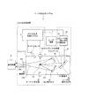
3.1構成
図1に、例示的なLPP方式のEUV光生成装置の構成を概略的に示す。EUV光生成装置1は、少なくとも1つのレーザ装置3と共に用いられてもよい。ここでは、EUV光生成装置1及びレーザ装置3を含むシステムを、以下、EUV光生成システム11と称する。
3. 3. Overview of EUV Light Generation Device 3.1 Configuration FIG. 1 schematically shows a configuration of an exemplary LPP EUV light generation device. The EUV
EUV光生成装置1は、例えば、チャンバ2及びドロップレット生成器26を含んでもよい。チャンバ2は、密閉可能であってもよい。ドロップレット生成器26は、例えば、チャンバ2の壁に取り付けられてもよい。ドロップレット生成器26から供給されるターゲットの材料は、スズ、テルビウム、ガドリニウム、リチウム、キセノン、又はそれらのうちのいずれかを組み合わせたものでもよいが、これらに限定されない。
The EUV
チャンバ2の壁には、少なくとも1つの貫通孔が設けられてもよい。その貫通孔をレーザ装置3から出力されたパルスレーザ光32が通過するようにしてもよい。チャンバ2には、レーザ装置3から出力されたパルスレーザ光32が透過する少なくとも1つのウィンドウ21が設けられてもよい。
The wall of the
チャンバ2の内部には、例えば、回転楕円面形状の反射面を有するEUV集光ミラー23が配置されてもよい。EUV集光ミラー23は、第1の焦点、及び第2の焦点を有してもよい。EUV集光ミラー23の表面には、例えば、モリブデンとシリコンとが交互に積層された多層反射膜が形成されてもよい。
In the
EUV集光ミラー23は、例えば、その第1の焦点がプラズマ発生位置(プラズマ生成領域25)又はその近傍に位置し、その第2の焦点が露光装置の仕様によって規定される所望の集光位置(中間焦点(IF)292)に位置するように配置されるのが好ましい。EUV集光ミラー23の中央部には、パルスレーザ光33が通過することができる貫通孔24が設けられてもよい。
For example, the
EUV光生成装置1は、EUV光生成制御システム5を含んでもよい。また、EUV光生成装置1は、ターゲットセンサ4を含んでもよい。ターゲットセンサ4は、ターゲットの存在、軌道、位置の少なくとも1つを検出してもよい。ターゲットセンサ4は、撮像機能を有していてもよい。
The EUV
更に、EUV光生成装置1は、チャンバ2内部と露光装置6内部とを連通する接続部29を含んでもよい。接続部29内部には、アパーチャが形成された壁291を設けてもよい。壁291は、そのアパーチャがEUV集光ミラー23の第2の焦点位置に位置するように配置してもよい。
Further, the EUV
更に、EUV光生成装置1は、レーザ光進行方向制御装置34、レーザ光集光ミラー22、ターゲット27を回収するターゲット回収器28などを含んでもよい。レーザ光進行方向制御装置34は、レーザ光の進行方向を制御するために、レーザ光の進行方向を規定する光学素子と、この光学素子の位置または姿勢を調整するためのアクチュエータとを備えてもよい。
Further, the EUV
3.2 動作
図1を参照すると、レーザ装置3から出力されたパルスレーザ光31は、レーザ光進行方向制御装置34を経て、パルスレーザ光32としてウィンドウ21を透過して、チャンバ2内に入射されてもよい。パルスレーザ光32は、少なくとも1つのレーザビーム経路に沿ってチャンバ2内に進み、レーザ光集光光学系22で反射されてもよい。そして、パルスレーザ光33として、少なくとも1つのドロップレットターゲット27に照射されてもよい。
3.2 Operation Referring to FIG. 1, the
ドロップレット生成器26は、ドロップレットターゲット27をチャンバ2内部のプラズマ生成領域25に向けて出力してもよい。ドロップレットターゲット27には、パルスレーザ光33に含まれる少なくとも1つのパルスが照射されてもよい。レーザ光が照射されたドロップレットターゲット27はプラズマ化し、そのプラズマからEUV光251が生成されてもよい。EUV光251は、EUV集光ミラー23によって反射されるとともに集光されてもよい。EUV集光ミラー23に反射されたEUV光252は、中間焦点292を通って露光装置6に出力されてもよい。なお、1つのドロップレットターゲット27に、パルスレーザ光33に含まれる複数のパルスレーザ光が照射されてもよい。
The droplet generator 26 may output the
EUV光生成制御システム5は、EUV光生成システム11全体の制御を統括してもよい。EUV光生成制御システム5は、ターゲットセンサ4によって撮像されたドロップレットターゲット27のイメージデータ等を処理してもよい。EUV光生成制御システム5は、例えば、ドロップレットターゲット27を出力するタイミングの制御およびドロップレットターゲット27の出力方向の制御の内の少なくとも1つを行ってもよい。EUV光生成制御システム5は、例えば、レーザ装置3のレーザ発振タイミングの制御、パルスレーザ光32の進行方向の制御、及びパルスレーザ光33の集光位置の制御の内の少なくとも1つを行ってもよい。上述の様々な制御は単なる例示に過ぎず、必要に応じて他の制御を追加してもよい。
The EUV light generation control system 5 may control the entire EUV light generation system 11. The EUV light generation control system 5 may process image data of the
4.増幅器システムを含むレーザ装置
4.1 構成
図2は、一実施形態に係るレーザ装置3の概略を示す図である。
4). Laser Device Including Amplifier System 4.1 Configuration FIG. 2 is a diagram schematically illustrating a
図2に例示されるように、レーザ装置3は、レーザコントローラLCと、マスターオシレータMOと、少なくとも1つ以上の増幅器PAと、少なくとも1つ以上のモニタMと、少なくとも1つ以上の制御部CONと、少なくとも1つ以上のゲイン調節部GCと、を含んでもよい。たとえば、n台の増幅器PA1〜PAnにそれぞれ対応したモニタM1〜Mnと、制御部CON1〜CONnと、ゲイン調節部GC1〜GCnとを含んでもよい。
As illustrated in FIG. 2, the
少なくとも1つ以上の増幅器PAは、マスターオシレータMOから出力されるパルスレーザ光の光路上に配置してもよい。増幅器PA1〜PAnは、CO2レーザガスを媒質としてもよい。 At least one or more amplifiers PA may be arranged on the optical path of the pulse laser beam output from the master oscillator MO. The amplifiers PA1 to PAn may use CO 2 laser gas as a medium.
少なくとも1つ以上のモニタMは、マスターオシレータMOから出力されるパルスレーザ光の光路上であって、増幅器PAの出射側に配置してもよい。モニタM1〜Mnは、増幅器PA1〜PAnからそれぞれ出力された自励発生光のエネルギを検出するエネルギ検出器を構成してもよい。 At least one monitor M may be disposed on the light path of the pulse laser beam output from the master oscillator MO and on the emission side of the amplifier PA. The monitors M1 to Mn may constitute an energy detector that detects the energy of the self-excited light output from the amplifiers PA1 to PAn, respectively.
レーザコントローラLCは、マスターオシレータMO及び制御部CON1〜CONnと、信号ラインを介して接続されてもよい。 The laser controller LC may be connected to the master oscillator MO and the control units CON1 to CONn via signal lines.
モニタM1〜Mnの出力信号は、それぞれ制御部CON1〜CONnに入力されてもよい。制御部CON1〜CONnの出力信号は、それぞれゲイン調節部GC1〜GCnに入力されてもよい。ゲイン調節部GC1〜GCnの出力信号は、それぞれ増幅器PA1〜PAnに入力されてもよい。増幅器PA1〜PAnは、ゲイン調節部GC1〜GCnの出力信号に従って放電が調節され、増幅ゲインが制御されてもよい。 The output signals of the monitors M1 to Mn may be input to the control units CON1 to CONn, respectively. The output signals of the control units CON1 to CONn may be input to the gain adjustment units GC1 to GCn, respectively. The output signals of the gain adjusters GC1 to GCn may be input to the amplifiers PA1 to PAn, respectively. The amplifiers PA1 to PAn may have their discharge adjusted in accordance with the output signals of the gain adjusters GC1 to GCn, and the amplification gain may be controlled.
4.2 動作
図3は、レーザコントローラLCが自励発振を抑制する制御のフローチャートを示す図である。図3は、実質的にはレーザコントローラLCが全ての制御部CONに自励発振光のエネルギを計測させる動作であってよい。しかし、この過程で各制御部CONは、各増幅器PAの制御パラメータ値が、自励発振が抑制可能な範囲となるように特定してもよい。EUV光生成のため、マスターオシレータMOから出力されたシードレーザ光を増幅器PAkで増幅して出力する場合、図3の動作で特定された範囲のパラメータ値を制御に用いてもよい。
4.2 Operation FIG. 3 is a diagram showing a flowchart of control in which the laser controller LC suppresses self-excited oscillation. 3 may be an operation in which the laser controller LC substantially measures the energy of the self-excited oscillation light by all the control units CON. However, in this process, each control unit CON may specify the control parameter value of each amplifier PA in a range in which self-oscillation can be suppressed. When the seed laser light output from the master oscillator MO is amplified and output by the amplifier PAk for EUV light generation, the parameter values in the range specified by the operation of FIG. 3 may be used for control.
まず、ステップ1で、レーザコントローラLCは、マスターオシレータMOへ、パルスレーザ光の出力を停止させる信号を送信してもよい(ST1)。
First, in
次に、ステップ2で、レーザコントローラLCは、制御部CON1〜CONnへ、すべての増幅器PA1〜PAnの増幅ゲインを0とする信号を送信してもよい(ST2)。この結果、ゲイン調節部GC1〜GCnは、すべての増幅器PA1〜PAnにおける放電を停止してもよい。
Next, in
次に、ステップ3で、引数kをk=1としてもよい(ST3)。
Next, in
次に、ステップ4で、レーザコントローラLCは、制御部CONkに自励発振光のエネルギを計測するための信号を送信してもよい(ST4)。たとえばレーザコントローラLCは、k=1である場合、制御部CON1に信号を送信してもよい。信号を受信した制御部CONkは、図4に示す動作を実行して、自励発振が抑制可能なパラメータ値の範囲を特定してもよい。 Next, in step 4, the laser controller LC may transmit a signal for measuring the energy of the self-oscillation light to the control unit CONk (ST4). For example, when k = 1, the laser controller LC may transmit a signal to the control unit CON1. The control unit CONk that has received the signal may execute the operation shown in FIG. 4 to identify the parameter value range in which self-excited oscillation can be suppressed.
次に、ステップ5で、レーザコントローラLCは、増幅器PAkの自励発振光のエネルギの計測を終了したか否かを判定してもよい(ST5)。ステップ5は、計測が終了するまで実行してもよい。自励発振光のエネルギの計測を終了したか否かは、たとえば制御部CONkが、後述する全てのパラメータ値に対する自励発振光のエネルギ値を受信したかどうかに基づいて判定してもよい。 Next, in step 5, the laser controller LC may determine whether or not the measurement of the energy of the self-oscillation light of the amplifier PAk is finished (ST5). Step 5 may be executed until the measurement is completed. Whether or not the measurement of the self-oscillation light energy has ended may be determined, for example, based on whether or not the control unit CONk has received the energy values of the self-oscillation light with respect to all parameter values to be described later.
ステップ5において、レーザコントローラLCが第k番目の増幅器PAkの自励発振光のエネルギの計測を終了したと判定した場合、ステップ6において、k=k+1としてもよい(ST6)。 If it is determined in step 5 that the laser controller LC has finished measuring the energy of the self-oscillation light of the kth amplifier PAk, k = k + 1 may be set in step 6 (ST6).
次に、ステップ7で、レーザコントローラLCは、k=nであるか否かを判定してもよい(ST7)。ステップ7において、k=nでない場合、ステップ4に戻ってもよい。ステップ7において、k=nである場合、レーザコントローラLCの制御を終了してもよい。 Next, in step 7, the laser controller LC may determine whether k = n (ST7). In step 7, when k = n is not true, the process may return to step 4. In step 7, when k = n, the control of the laser controller LC may be terminated.
図4は、制御部CONの制御フローチャートを示す図である。 FIG. 4 is a diagram illustrating a control flowchart of the control unit CON.
制御部CONkによる制御は、図3に示したレーザコントローラLCによる制御のステップ4の段階で実行してもよい。 The control by the control unit CONk may be executed in the step 4 of the control by the laser controller LC shown in FIG.
まず、ステップ11で、制御部CONkは、増幅器PAkの放電を開始させる信号をゲイン調節部GCkを介して、第k増幅器PAkの図示しない電源に送信してもよい(ST11)。 First, in step 11, the control unit CONk may transmit a signal for starting the discharge of the amplifier PAk to a power supply (not shown) of the kth amplifier PAk via the gain adjustment unit GCk (ST11).
次に、ステップ12で、制御部CON1は、ゲイン調節部GCkに、パラメータを設定するために、たとえばL種類のパラメータ値(P1,P2,・・・Pi,・・・PL)を不図示のメモリ等から読み出してもよい(ST12)。パラメータ値は、電圧又はデューティ比でもよい。 Next, in step 12, the control unit CON1 sets, for example, L types of parameter values (P1, P2,... Pi,... PL) to the gain adjustment unit GCk in order to set parameters. You may read from a memory etc. (ST12). The parameter value may be a voltage or a duty ratio.
次に、ステップ13で、制御部CONkは、引数iをi=1としてもよい(ST13)。 Next, in step 13, the control unit CONk may set the argument i to i = 1 (ST13).
次に、ステップ14で、制御部CONkは、ゲイン調節部GCkにパラメータ値Piを設定してもよい(ST14)。 Next, in step 14, the control unit CONk may set the parameter value Pi in the gain adjustment unit GCk (ST14).
次に、ステップ15で、制御部CONkは、ゲイン調節部GCkに設定したパラメータ値Piを含む制御信号を送信してもよい(ST15)。これにより、第k増幅器PAkが設定されたパラメータ値Piによって動作してよい。このとき、モニタMkが自励発振光のエネルギEi値を計測してもよい。 Next, in step 15, the control unit CONk may transmit a control signal including the parameter value Pi set in the gain adjustment unit GCk (ST15). Thereby, the k-th amplifier PAk may operate with the set parameter value Pi. At this time, the monitor Mk may measure the energy Ei value of the self-excited oscillation light.
次に、ステップ16で、制御部CONkは、モニタMkが計測した自励発振光のエネルギEi値の信号を受信してもよい(ST16)。 Next, at step 16, the control unit CONk may receive a signal of the energy Ei value of the self-excited oscillation light measured by the monitor Mk (ST16).
次に、ステップ17で、制御部CONkは、Ei≦E0であるか否かを判定してもよい(ST17)。ここで、E0は、自励発振が許容されるエネルギであり、レーザ光路上に配置された光学部品のダメージ閾値等に基づいて決定されてもよい。E0は、好ましくは、0であってもよい。 Next, in step 17, the control unit CONk may determine whether or not Ei ≦ E0 (ST17). Here, E0 is energy allowing self-excited oscillation, and may be determined based on a damage threshold value of an optical component arranged on the laser optical path. E0 may preferably be 0.
ステップ17において、Ei≦E0でない場合、ステップ19に進んでもよい。 In step 17, if Ei ≦ E0 is not satisfied, the process may proceed to step 19.
ステップ17においてE1≦E0である場合、ステップ18で、パラメータ値Piを自励発振抑制パラメータ値としてメモリに記憶してもよい(ST18)。 If E1 ≦ E0 in step 17, the parameter value Pi may be stored in the memory as a self-oscillation suppression parameter value in step 18 (ST18).
次に、ステップ19で、i=i+1と設定してもよい(ST19)。 Next, in step 19, i = i + 1 may be set (ST19).
次に、ステップ20で、i=Lであるか否かを判定してもよい(ST20)。 Next, in step 20, it may be determined whether i = L (ST20).
ステップ20において、i=Lでない場合、ステップ14に戻ってもよい。 In step 20, when i = L is not satisfied, the process may return to step 14.
ステップ20において、i=Lである場合、制御部CONkは増幅器PAkの放電を停止してもよい。 In step 20, when i = L, the controller CONk may stop discharging the amplifier PAk.
以上の動作は、まず、レーザコントローラLCは、マスターオシレータMOへパルスレーザ光の出力を停止させる信号を送信してもよい。次に、レーザコントローラLCは、制御部CONkを介して、すべての増幅器PAkのゲインが0となるような信号を送信し、放電を停止させてもよい。その後、レーザコントローラLCは、各制御部CONkに自励発振光のエネルギを計測させるための信号を送信してもよい。 In the above operation, first, the laser controller LC may transmit a signal for stopping the output of the pulsed laser light to the master oscillator MO. Next, the laser controller LC may stop the discharge by transmitting a signal such that the gains of all the amplifiers PAk become 0 through the control unit CONk. Thereafter, the laser controller LC may transmit a signal for causing each control unit CONk to measure the energy of the self-oscillation light.
制御部CON1は、ゲイン調節部GC1を介して、増幅器PA1のゲインを変更するために、対応するパラメータ値を順次変更する信号を送信してもよい。制御部CON1は、モニタM1を介して都度得られた自励発振光のエネルギ値の信号とそのときのパラメータ値から、自励発振が抑制されるパラメータ値の範囲を求めてもよい。そして、制御部CON1は、自励発振が抑制されるパラメータ値の範囲を記憶してもよい。その後、制御部CON1は、増幅器PA1のゲインが0となるような信号を送信し、放電を停止させてもよい。 The control unit CON1 may transmit a signal for sequentially changing the corresponding parameter value in order to change the gain of the amplifier PA1 via the gain adjustment unit GC1. The control unit CON1 may obtain a parameter value range in which the self-excited oscillation is suppressed from the energy value signal of the self-excited oscillation light obtained each time via the monitor M1 and the parameter value at that time. Then, the control unit CON1 may store a parameter value range in which self-excited oscillation is suppressed. Thereafter, the control unit CON1 may stop the discharge by transmitting a signal such that the gain of the amplifier PA1 becomes zero.
制御部CON2〜CONnは、順次、制御部CON1と同様の処理を実行することができ、対応する増幅器PA2〜PAnの自励発振を抑制するパラメータ値の範囲をそれぞれ求めて、記憶してもよい。 The control units CON2 to CONn can sequentially execute the same processing as that of the control unit CON1, and each parameter value range for suppressing the self-oscillation of the corresponding amplifiers PA2 to PAn may be obtained and stored. .
マスターオシレータMOから出力されたパルスレーザ光を増幅器PAkで増幅して出力する際、制御部CONkは、対応する増幅器PAkの自励発振が抑制可能な、予め記憶しておいたパラメータ値の範囲内で、それぞれの増幅器PAkを制御することが可能となってよい。 When the pulse laser beam output from the master oscillator MO is amplified by the amplifier PAk and output, the control unit CONk can suppress the self-excited oscillation of the corresponding amplifier PAk and is within the range of parameter values stored in advance. Thus, it may be possible to control each amplifier PAk.
4.3 作用
増幅器PAkの自励発振を抑制可能なパラメータ値の範囲を予め計測し、そのパラメータ値の範囲内でその増幅器PAkを制御するので、増幅器PAkの自励発振を抑制することが可能となってよい。
4.3 Action Since the range of the parameter value that can suppress the self-excited oscillation of the amplifier PAk is measured in advance and the amplifier PAk is controlled within the range of the parameter value, the self-excited oscillation of the amplifier PAk can be suppressed. It may be.
5.モニタを含む増幅器
5.1 構成
図5Aは、一実施形態に係る増幅器PAの増幅チャンバ7の概略を示す。図5Bは、一実施形態に係るモニタMを含む増幅部の概略を示す。
5. Amplifier including Monitor 5.1 Configuration FIG. 5A schematically shows an amplification chamber 7 of an amplifier PA according to an embodiment. FIG. 5B schematically shows an amplification unit including the monitor M according to an embodiment.
増幅部は、増幅器PAkと、ゲイン調節部GCkと、第1モニタMk1と、第2モニタMk2と、制御部CONkと、を含んでもよい。 The amplifying unit may include an amplifier PAk, a gain adjusting unit GCk, a first monitor Mk1, a second monitor Mk2, and a control unit CONk.
増幅器PAkは、スラブ型増幅器であって、増幅チャンバ7と、電源8と、を含んでもよい。
The amplifier PAk is a slab type amplifier, and may include an amplification chamber 7 and a
増幅チャンバ7は、例えば、入射ウィンドウ71と、出射ウィンドウ72と、第1凹面ミラー73と、第2凹面ミラー74と、第1電極75と、第2電極76と、を備えてもよい。
The amplification chamber 7 may include, for example, an
入射ウィンドウ71および出射ウィンドウ72は、レーザ光の光路上に配置してもよい。入射ウィンドウ71および出射ウィンドウ72は、増幅チャンバ7を密閉してもよい。
The
第1電極75及び第2電極76は、増幅チャンバ7の内部に所定の間隔を保って互いに対向して配置されてもよい。第1電極75及び第2電極76は、レーザ光の光路をはさむように配置してもよい。
The
第1凹面ミラー73及び第2凹面ミラー74は、入射ウィンドウ71を介して増幅チャンバ7に入射したレーザ光が、第1電極75及び第2電極76間を所定の光路でマルチパスするように配置してもよい。
The first
増幅チャンバ7は、CO2レーザガスを内部に封入してもよい。 The amplification chamber 7 may enclose CO 2 laser gas inside.
電源8は、第1電極75及び第2電極76に接続されてもよい。
The
ゲイン調節部GCkは、電源8と制御部CONkに信号ラインを介して接続されてもよい。
The gain adjustment unit GCk may be connected to the
第1モニタMk1は、増幅チャンバ7に入射するレーザ光の光路上に配置されてもよい。第2モニタMk2は、増幅チャンバ7から出射するレーザ光の光路上に配置されてもよい。 The first monitor Mk1 may be disposed on the optical path of the laser light incident on the amplification chamber 7. The second monitor Mk2 may be disposed on the optical path of the laser light emitted from the amplification chamber 7.
第1モニタMk1は、例えば、第1ビームスプリッタBSk1と、第1エネルギ検出器ESk1とを備えてよい。同様に第2モニタMk2は、第2ビームスプリッタBSk2と、第2エネルギ検出器ESk2とを備えてもよい。 For example, the first monitor Mk1 may include a first beam splitter BSk1 and a first energy detector ESk1. Similarly, the second monitor Mk2 may include a second beam splitter BSk2 and a second energy detector ESk2.
第1ビームスプリッタBSk1は、増幅チャンバ7に入射するレーザ光の光路上に設置されてもよい。第1ビームスプリッタBSk1は、増幅器PAkから出力された光の一部を反射して、第1エネルギ検出器ESk1に導くように配置してもよい。同様に、第2ビームスプリッタBSk2は、増幅チャンバ7から出射するレーザ光の光路上に設置され、増幅器PAkから出力された光の一部を反射して、第2エネルギ検出器ESk1に導いてもよい。 The first beam splitter BSk1 may be installed on the optical path of the laser light incident on the amplification chamber 7. The first beam splitter BSk1 may be arranged to reflect a part of the light output from the amplifier PAk and guide it to the first energy detector ESk1. Similarly, the second beam splitter BSk2 is installed on the optical path of the laser beam emitted from the amplification chamber 7, and reflects a part of the light output from the amplifier PAk and guides it to the second energy detector ESk1. Good.
制御部CONkは、信号ラインを介して、ゲイン調節部GCk、第1モニタMk1及び第2モニタMk2に接続されてもよい。 The control unit CONk may be connected to the gain adjustment unit GCk, the first monitor Mk1, and the second monitor Mk2 via a signal line.
5.2 動作
図5Bに示す制御部CONkにおいて、増幅器PAkのゲインを制御するパラメータ値の一例として励起強度Dを利用した場合の動作を、図3及び図4に示したフローチャートにしたがって説明する。
5.2 Operation An operation when the excitation intensity D is used as an example of a parameter value for controlling the gain of the amplifier PAk in the control unit CONk shown in FIG. 5B will be described according to the flowcharts shown in FIGS.
レーザコントローラLCは、シードレーザ光が増幅器PAkに入射されることがないように、図1に示したマスターオシレータMOからのパルスレーザ光の出力を停止させる信号を送信してもよい。また、レーザコントローラLCは、増幅器PAkの放電を停止させる信号を送信してもよい。 The laser controller LC may transmit a signal for stopping the output of the pulsed laser light from the master oscillator MO shown in FIG. 1 so that the seed laser light is not incident on the amplifier PAk. Further, the laser controller LC may transmit a signal for stopping the discharge of the amplifier PAk.
制御部CONkは、ゲイン調節部GCkを介して、電源8を制御し、放電の励起強度値Dが所定の範囲(D1,D2,・・・Di,・・・DL)で変化するように、第1電極75及び第2電極76間に印加する電位差を調整する信号を送信してもよい。
The controller CONk controls the
制御部CONkは、第1モニタMk1及び第2モニタMk2を用いて、励起強度値(D1,D2,・・・Di,・・・DL)に対応する自励発振光のエネルギ(E1,E2,・・・Ei,・・・EL)を求めてもよい。各自励発振光のエネルギ値Eは、第1モニタMk1及び第2モニタMk2で得られた値の和であってもよい。 The control unit CONk uses the first monitor Mk1 and the second monitor Mk2, and uses the energy (E1, E2, E2) of the self-excited oscillation light corresponding to the excitation intensity values (D1, D2,... Di,... DL). ... Ei,... EL) may be obtained. The energy value E of each self-oscillation light may be a sum of values obtained by the first monitor Mk1 and the second monitor Mk2.
制御部CONkは、自励発振光のエネルギが許容値E0以下となるような励起強度値Dの範囲を記憶してもよい。制御部CONkは、図1に示したマスターオシレータMOから出力されたシードレーザ光を増幅器PAkで増幅して出力させる際、記憶された励起強度値Dの範囲内で、増幅器PAkを制御してもよい。 The controller CONk may store a range of the excitation intensity value D such that the energy of the self-excited oscillation light is equal to or less than the allowable value E0. When the seed laser beam output from the master oscillator MO shown in FIG. 1 is amplified and output by the amplifier PAk, the control unit CONk controls the amplifier PAk within the range of the stored excitation intensity value D. Good.
5.3 作用
増幅器PAkの自励発振を抑制可能な励起強度値Dをあらかじめ計測し、その励起強度値Dの範囲内で、増幅器PAkを制御するので、自励発振を抑制することが可能となる。
5.3 Action Since the excitation intensity value D capable of suppressing the self-excited oscillation of the amplifier PAk is measured in advance and the amplifier PAk is controlled within the range of the excitation intensity value D, the self-excited oscillation can be suppressed. Become.
5.4 その他
本開示において、自励発振光のエネルギを計測するために、第1モニタMk1及び第2モニタMk2を増幅器PAkの入射側と出射側の光路上に配置しているが、入射側と出射側のどちらか一方に配置してもよい。
5.4 Others In the present disclosure, in order to measure the energy of the self-oscillation light, the first monitor Mk1 and the second monitor Mk2 are arranged on the optical path on the incident side and the emission side of the amplifier PAk. It may be arranged on either the output side or the output side.
励起強度値Dを変化させるパラメータとして、第1電極75と第2電極76間に印加する電位差、または高周波のパルス幅変調PWM(Pulse Width Modulation)におけるデューティ比、もしくはPWMにおけるサイクルを制御してもよい。
As a parameter for changing the excitation intensity value D, a potential difference applied between the
CO2レーザガスを含むスラブ型の増幅器に代えて、高速軸流型の増幅器または3軸直交型の増幅器を用いてもよい。 Instead of the slab type amplifier containing the CO 2 laser gas, a high-speed axial flow type amplifier or a three-axis orthogonal type amplifier may be used.
6.ガス調節部を含む増幅器システム
6.1 構成
図6は、一実施形態に係るガス調節部91を含む増幅器PAの概略を示す。
6). 6. Amplifier System Including Gas Control Unit 6.1 Configuration FIG. 6 shows an outline of an amplifier PA including a
ガス調節部91を含む増幅器PAkは、図5に示したスラブ型増幅器に、例えば、ガス調節部91と、Xeガス供給部92と、ガス排気部93と、を追加した構成であってもよい。
The amplifier PAk including the
ガス供給部92は、例えば、Xeガスボンベ92a、レーザガスボンベ92b、第1バルブ92c、及び第2バルブ92dを含んでもよい。
The
Xeガスを含むXeガスボンベ92aの配管は、第1バルブ92cを介して、増幅チャンバ7に接続されてもよい。レーザガスを含むレーザガスボンベ92bの配管は、第2バルブ92dを介して、増幅チャンバ7に接続されてもよい。
The piping of the
Xeガスを含むXeガスボンベ92aは、100%Xeガスであってもよいし、レーザガスを含んでもよい。レーザガスは、Xeガスを含まないレーザガスボンベ92bであってもよい。例えば、CO2ガス、N2ガス、Heガス、COガス、O2ガスを所定の濃度で混合したガスであってもよい。
The
ガス排気部93は、排気バルブ93a及び排気ポンプ93bを含んでもよい。排気バルブ93aは、増幅チャンバ7と真空ポンプ94の間の配管に接続されてもよい。
The
ガス調節部91は、第1バルブ92c、第2バルブ92d、及び排気バルブ93aを開閉させる信号ラインと、排気ポンプ93bを動作させる信号ラインに接続されてもよい。ガス調節部91は、増幅チャンバ7内の圧力を計測する図示しない圧力センサの信号及びゲイン調節部GCkからの出力信号が入力されてもよい。
The
6.2 動作
図7は、制御部CONの制御フローチャートを示す図である。
6.2 Operation FIG. 7 is a diagram illustrating a control flowchart of the control unit CON.
まず、ステップ21で、制御部CONkは、増幅器PAkの放電を開始させる信号を、ゲイン調節部GCkを介して電源8に送信してもよい(ST21)。
First, in step 21, the control unit CONk may transmit a signal for starting the discharge of the amplifier PAk to the
次に、ステップ22で、制御部CON1は、ゲイン調節部GCkに、Xe濃度を設定するためのパラメータ値(C1,C2,・・・Ci,・・・CL)を不図示のメモリから読み出してもよい(ST22)。
Next, in
次に、ステップ23で、制御部CON1は、引数iをi=1としてもよい(ST23)。
Next, in
次に、ステップ24で、制御部CON1は、ゲイン調節部GCkに最大ゲインを発生する励起強度値DmaxとXeガス濃度パラメータ値Ciを設定してもよい(ST24)。 Next, in step 24, the control unit CON1 may set the excitation intensity value Dmax and the Xe gas concentration parameter value Ci that generate the maximum gain in the gain adjusting unit GCk (ST24).
次に、ステップ25で、ゲイン調節部GCkは、最大ゲインの励起強度値Dmaxとなるように電源8を調節すると共に、Xeガス濃度パラメータ値がCiとなるようにガス調節部91を調節する信号を送信してもよい(ST25)。これにより、第k増幅器PAkは最大ゲインの励起強度値かつ設定されたXeガス濃度で動作してよい。このとき、モニタMkが自励発振光のエネルギEi値を計測してもよい。
Next, in
次に、ステップ26で、制御部CON1は、モニタMkによって計測された自励発振光のエネルギEiを受信してもよい(ST26)。 Next, in step 26, the controller CON1 may receive the energy Ei of the self-oscillation light measured by the monitor Mk (ST26).
次に、ステップ27で、制御部CON1は、Ei≦E0であるか否かを判定してもよい(ST27)。
Next, in
ステップ27において、Ei≦E0でない場合、ステップ29に進んでもよい。
In
ステップ27において、E1≦E0である場合、ステップ28で、Xeガス濃度パラメータ値Ciを自励発振抑制可能なXeガス濃度値としてメモリに記憶してもよい(ST28)。
If E1 ≦ E0 in
次に、ステップ29で、制御部CON1は、i=i+1と設定してもよい(ST29)。
Next, in
次に、ステップ30で、制御部CON1は、i=Lであるか否かを判定してもよい(ST30)。 Next, in step 30, the control unit CON1 may determine whether i = L (ST30).
ステップ30において、i=Lでない場合、ステップ24に戻ってもよい。 If i is not equal to L in step 30, the process may return to step 24.
ステップ30において、i=Lである場合、ステップ31で、メモリに記憶されたXe濃度の最大値Cmaxを求めてもよい(ST31)。 In step 30, if i = L, the maximum value Cmax of the Xe concentration stored in the memory may be obtained in step 31 (ST31).
次に、ステップ32で、増幅チャンバ7内のレーザガス中のXe濃度がCmaxとなるようにXe濃度を調節してもよい(ST32)。その後、制御を終了してもよい。
Next, in
以上の動作は、まず、レーザコントローラLCは、マスターオシレータMOへパルスレーザ光の出力を停止させる信号を送信してもよい。次に、レーザコントローラLCは、制御部CONkを介して、すべての増幅器PAkのゲインが0となるような信号を送信し、放電を停止させてもよい。その後、レーザコントローラLCは、各制御部CONkに自励発振光のエネルギを計測させるための信号を送信してもよい。 In the above operation, first, the laser controller LC may transmit a signal for stopping the output of the pulsed laser light to the master oscillator MO. Next, the laser controller LC may stop the discharge by transmitting a signal such that the gains of all the amplifiers PAk become 0 through the control unit CONk. Thereafter, the laser controller LC may transmit a signal for causing each control unit CONk to measure the energy of the self-oscillation light.
制御部CON1は、ゲイン調節部GC1を介して電源8を制御し、ゲインが最大となる励起強度Dmaxを設定し、所定のXe濃度範囲(C1,C2,・・・Ci,・・・CL)において、レーザガス中のXe濃度Cを変化させてもよい。
The control unit CON1 controls the
制御部CON1は、Xe濃度Cの値に応じて、自励発振光のエネルギ(E1,E2,・・・Ei,・・・EL)を、モニタを用いて検出してもよい。制御部CON1は、自励発振光のエネルギの許容値E0以下の最大のXe濃度Cmaxの値を記憶してもよい。 The control unit CON1 may detect the self-excited oscillation light energy (E1, E2,... Ei,... EL) using a monitor according to the value of the Xe concentration C. The controller CON1 may store the maximum Xe concentration Cmax value that is equal to or less than the allowable value E0 of the energy of the self-excited oscillation light.
マスターオシレータMOから出力されたシードレーザ光を増幅器PAkで増幅して出力する際、制御部CONkは、増幅器PAkの自励発振を抑制可能な、記憶されたXe濃度Cmaxとなるように、増幅チャンバ7内のXeガス濃度を調節してもよい。 When the seed laser light output from the master oscillator MO is amplified and output by the amplifier PAk, the control unit CONk can control the self-excited oscillation of the amplifier PAk so that the stored Xe concentration Cmax can be obtained. The Xe gas concentration in 7 may be adjusted.
次に、ガス調節部91がXeガス濃度を調節する動作について説明する。
Next, an operation in which the
ガス調節部91は、最初に第1バルブ92a及び第2バルブ92bを閉めた状態で、排気ポンプ93bを動作させた後、排気バルブ93aを開けるよう、第1バルブ92a、第2バルブ92b、排気ポンプ93b、排気バルブ93aに各々信号を送信してもよい。これにより、増幅器PAk内を排気してもよい。そして、図示しない圧力センサの検出値が所定の低圧に到達した場合、ガス調節部91は、排気バルブ93aを閉じる信号を送信してもよい。
The
そして、ガス調節部91は、第2バルブ92dを開け、レーザガスを供給し、全圧Tpとなったら、第2バルブ92dを閉じる信号を送信してもよい。この状態で、放電させれば、Xe濃度0の際の自励発振光のエネルギを計測することが可能となる。
And the
次に、排気バルブ93aを開けて、所定の圧力Txeとなったら、ガス調節部91は、排気バルブ93aを閉じる信号を送信してもよい。そして、ガス調節部91は、第1バルブ92cを開け、Xeを含むガスを供給し、全圧Tpとなったら、第1バルブ92cを閉じる信号を送信してもよい。
Next, when the
この状態で、放電させれば、所定のXe濃度における自励発振光のエネルギを計測することが可能となる。 If discharged in this state, the energy of self-oscillation light at a predetermined Xe concentration can be measured.
ガス調節部91は、以上のような動作を異なるTxeに対して繰り返してもよい。これにより、Xe濃度をC1、C2・・・Ci、・・・CLまで変化させて、それぞれ対応する自励発振光のエネルギを計測することが可能となる。
The
引き続き異なるXe濃度で自励発振光のエネルギを計測する場合、増幅器PAk内を所定の低圧まで排気して上記処理を行ってもよいし、一部を排気して上記処理をおこなってもよい。 When the energy of the self-excited oscillation light is continuously measured at different Xe concentrations, the above processing may be performed by exhausting the inside of the amplifier PAk to a predetermined low pressure, or may be performed by exhausting a part thereof.
6.3 作用
増幅器PAkの自励発振を抑制可能なゲイン調節部GCkのXe濃度Cmaxをあらかじめ計測し、そのXe濃度Cmaxで、増幅器PAkを動作させるので、自励発振を抑制することが可能となる。
6.3 Operation Since the Xe concentration Cmax of the gain adjusting unit GCk capable of suppressing the self-excited oscillation of the amplifier PAk is measured in advance and the amplifier PAk is operated at the Xe concentration Cmax, the self-excited oscillation can be suppressed. Become.
6.4 その他
本開示において、増幅器PAk内のXeガスの濃度を調節する例を示したが、CO2ガス濃度、N2ガス濃度、及び増幅チャンバ7内の全圧力のうち、少なくとも1つを調節してもよい。
In 6.4 Others present disclosure, an example of adjusting the concentration of Xe gas in the amplifier PAk, CO 2 gas concentration, N 2 gas concentration, and of the total pressure in the amplification chamber 7, at least one You may adjust.
CO2レーザガスを含むスラブ型の増幅器に代えて、高速軸流型の増幅器または3軸直交型の増幅器を用いてもよい。 Instead of the slab type amplifier containing the CO 2 laser gas, a high-speed axial flow type amplifier or a three-axis orthogonal type amplifier may be used.
また、レーザガスは、Xeガスを含まなくてもよい。例えば、CO2ガス、N2ガス、及び増幅チャンバ7内の全圧力のうち、少なくとも1つを調節して、増幅器PAkのゲインを調節してもよい。 The laser gas may not contain Xe gas. For example, the gain of the amplifier PAk may be adjusted by adjusting at least one of CO 2 gas, N 2 gas, and the total pressure in the amplification chamber 7.
図8は、Xe濃度と自励発振光のエネルギの関係を示す。 FIG. 8 shows the relationship between the Xe concentration and the energy of the self-oscillation light.
例えば、自励発振光のエネルギ許容値をE0とした場合、自励発振光のエネルギとXe濃度の関係曲線は、Xe濃度の増加にともなってE0を超えてもよい。このとき、関係曲線がE0を越える交点のXe濃度をCmaxとしてもよい。発明者らはスラブ型増幅器で試験した結果、実用的なE0を超えないXe濃度は、1%以下であるという知見を得た。 For example, when the allowable energy value of self-oscillation light is E0, the relationship curve between the self-oscillation light energy and the Xe concentration may exceed E0 as the Xe concentration increases. At this time, the Xe concentration at the intersection where the relationship curve exceeds E0 may be Cmax. As a result of testing with a slab type amplifier, the inventors have found that the Xe concentration not exceeding practical E0 is 1% or less.
さらに好ましい場合として、発明者らは、エネルギ検出器の検出限界以下の自励発振光の許容エネルギE0=0(W)におけるXe濃度は、0.72%であることを確認した。 As a more preferable case, the inventors have confirmed that the Xe concentration at the allowable energy E0 = 0 (W) of self-oscillation light below the detection limit of the energy detector is 0.72%.
上記の説明は、制限ではなく単なる例示を意図したものである。従って、添付の特許請求の範囲を逸脱することなく本開示の実施形態に変更を加えることができることは、当業者には明らかであろう。 The above description is intended to be illustrative only and not limiting. Thus, it will be apparent to one skilled in the art that modifications may be made to the embodiments of the present disclosure without departing from the scope of the appended claims.
本明細書及び添付の特許請求の範囲全体で使用される用語は、「限定的でない」用語と解釈されるべきである。例えば、「含む」又は「含まれる」という用語は、「含まれるものとして記載されたものに限定されない」と解釈されるべきである。「有する」という用語は、「有するものとして記載されたものに限定されない」と解釈されるべきである。また、本明細書、及び添付の特許請求の範囲に記載される不定冠詞「1つの」は、「少なくとも1つ」又は「1又はそれ以上」を意味すると解釈されるべきである。 Terms used throughout this specification and the appended claims should be construed as "non-limiting" terms. For example, the terms “include” or “included” should be interpreted as “not limited to those described as included”. The term “comprising” should be interpreted as “not limited to what is described as having”. Also, the indefinite article “a” or “an” in the specification and the appended claims should be interpreted to mean “at least one” or “one or more”.
1…EUV光生成装置、2…チャンバ、3…レーザ装置、4…ターゲットセンサ、5…EUV光生成制御システム、6…露光装置、11…EUV光生成システム、21…ウィンドウ、22…レーザ光集光ミラー、23…EUV集光ミラー、24…貫通孔、25…プラズマ生成領域、251…放射光、252…EUV光、26…ドロップレット生成器、27…ターゲット、28…ターゲット回収部、29…接続部、291…壁、292…中間集光点、31,32,33…パルスレーザ光、34…レーザ光進行方向制御装置、7…増幅チャンバ、71…入射ウィンドウ、72…出射ウィンドウ、73…第1凹面ミラー、74…第2凹面ミラー、75…第1電極、76…第2電極、8…電源、LC…レーザコントローラ、MO…マスターオシレータ、PA…増幅器、GC…ゲイン調節部、CON…制御部、M…モニタ
DESCRIPTION OF
Claims (10)
前記パルスレーザ光の光路上に配置された少なくとも1つの増幅器と、
前記増幅器の入射側と出力側のどちらか一方の前記光路に配置され、前記増幅器からの自励発振光のエネルギを検出するエネルギ検出器と、
前記増幅器のゲインを調節するゲイン調節部と、
前記マスターオシレータからパルスレーザ光が前記増幅器に入力されていない時の前記エネルギ検出器の検出結果に基づいて、前記ゲイン調節部を制御する制御部と、
を備えるレーザ装置。 A master oscillator that outputs pulsed laser light;
At least one amplifier disposed on the optical path of the pulsed laser light;
An energy detector that is disposed in the optical path on either the input side or the output side of the amplifier and detects energy of self-oscillation light from the amplifier;
A gain adjuster for adjusting the gain of the amplifier;
A control unit for controlling the gain adjustment unit based on a detection result of the energy detector when pulse laser light is not input to the amplifier from the master oscillator;
A laser apparatus comprising:
請求項1に記載のレーザ装置。 The laser apparatus according to claim 1, wherein the amplifier includes a CO 2 laser gas, and discharges the CO 2 laser gas.
請求項2に記載のレーザ装置。 The laser apparatus according to claim 2 , wherein the gain adjusting unit adjusts the composition of the CO 2 laser gas.
請求項3に記載のレーザ装置。 The laser device according to claim 3, wherein the gain adjusting unit adjusts the concentration of at least one of CO 2 , N 2 , and Xe in the laser gas.
請求項4に記載のレーザ装置。 The laser apparatus according to claim 4, wherein the gain adjusting unit adjusts the concentration of Xe gas to 1% or less.
請求項2に記載のレーザ装置。 The laser apparatus according to claim 2, wherein the gain adjusting unit includes a power source that adjusts excitation intensity due to discharge.
前記パルスレーザ光の光路上に配置された少なくとも1つの増幅器と、
を備え、
前記増幅器は、CO2レーザガスとしてXeガスを含む
スラブ型増幅器であるレーザ装置。 A master oscillator that outputs pulsed laser light;
At least one amplifier disposed on the optical path of the pulsed laser light;
With
The amplifier is a laser device which is a slab type amplifier containing Xe gas as a CO 2 laser gas.
請求項7に記載のレーザ装置。 The laser device according to claim 7, wherein the Xe concentration of the laser gas of the slab amplifier is 1% or less.
前記増幅器からの自励発振光のエネルギを検出するエネルギ検出器と、
前記マスターオシレータからパルスレーザ光が前記増幅器に入力されていない時の前記エネルギ検出器の検出結果に基づいて、前記増幅器のゲインを調節する制御部と、
を備えるレーザ装置。 At least one amplifier for amplifying the pulsed laser from the master oscillator;
An energy detector for detecting the energy of self-oscillation light from the amplifier;
A control unit that adjusts the gain of the amplifier based on a detection result of the energy detector when pulse laser light is not input to the amplifier from the master oscillator;
A laser apparatus comprising:
Priority Applications (2)
| Application Number | Priority Date | Filing Date | Title |
|---|---|---|---|
| PCT/IB2013/000356 WO2013144695A1 (en) | 2012-03-29 | 2013-03-08 | Laser apparatus, laser system, and extreme ultraviolet light generation apparatus |
| US14/455,669 US20140346375A1 (en) | 2012-03-29 | 2014-08-08 | Laser apparatus, laser system, and extreme ultraviolet light generation apparatus |
Applications Claiming Priority (2)
| Application Number | Priority Date | Filing Date | Title |
|---|---|---|---|
| US201261617446P | 2012-03-29 | 2012-03-29 | |
| US61/617,446 | 2012-03-29 |
Publications (1)
| Publication Number | Publication Date |
|---|---|
| JP2013207298A true JP2013207298A (en) | 2013-10-07 |
Family
ID=49526039
Family Applications (1)
| Application Number | Title | Priority Date | Filing Date |
|---|---|---|---|
| JP2013001704A Pending JP2013207298A (en) | 2012-03-29 | 2013-01-09 | Laser device, laser system and extreme-ultraviolet light generation device |
Country Status (2)
| Country | Link |
|---|---|
| US (1) | US20140346375A1 (en) |
| JP (1) | JP2013207298A (en) |
Cited By (3)
| Publication number | Priority date | Publication date | Assignee | Title |
|---|---|---|---|---|
| WO2016142995A1 (en) * | 2015-03-06 | 2016-09-15 | ギガフォトン株式会社 | Laser device and extreme ultraviolet light generation system |
| WO2018134971A1 (en) * | 2017-01-20 | 2018-07-26 | ギガフォトン株式会社 | Laser device and extreme ultraviolet light generation system |
| JPWO2017175561A1 (en) * | 2016-04-07 | 2019-02-14 | ギガフォトン株式会社 | Solid-state laser device, solid-state laser system, and laser device for exposure apparatus |
Families Citing this family (3)
| Publication number | Priority date | Publication date | Assignee | Title |
|---|---|---|---|---|
| JP5739099B2 (en) * | 2008-12-24 | 2015-06-24 | ギガフォトン株式会社 | Target supply device, control system thereof, control device thereof and control circuit thereof |
| US9755396B1 (en) * | 2016-11-29 | 2017-09-05 | Asml Netherlands B.V. | EUV LPP source with improved dose control by combining pulse modulation and pulse control mode |
| US10524345B2 (en) * | 2017-04-28 | 2019-12-31 | Taiwan Semiconductor Manufacturing Co., Ltd. | Residual gain monitoring and reduction for EUV drive laser |
Citations (3)
| Publication number | Priority date | Publication date | Assignee | Title |
|---|---|---|---|---|
| JP2006128157A (en) * | 2004-10-26 | 2006-05-18 | Komatsu Ltd | Driver laser system for extremely ultraviolet optical source apparatus |
| JP2010186990A (en) * | 2009-01-14 | 2010-08-26 | Komatsu Ltd | Laser light amplifier and laser apparatus using the same |
| JP2011159932A (en) * | 2010-02-04 | 2011-08-18 | Mitsubishi Electric Corp | Gas laser amplifier device and optical axis adjusting method thereof |
Family Cites Families (4)
| Publication number | Priority date | Publication date | Assignee | Title |
|---|---|---|---|---|
| US4870654A (en) * | 1987-05-22 | 1989-09-26 | California Laboratories, Inc. | Generation of multiply folded optical paths |
| US5715268A (en) * | 1994-01-24 | 1998-02-03 | Sdl, Inc. | Laser amplifiers with suppressed self oscillation |
| US7184204B2 (en) * | 2003-07-01 | 2007-02-27 | Lambda Physik Ag | Master-oscillator power-amplifier (MOPA) excimer or molecular fluorine laser system with long optics lifetime |
| JP2009246345A (en) * | 2008-03-12 | 2009-10-22 | Komatsu Ltd | Laser system |
-
2013
- 2013-01-09 JP JP2013001704A patent/JP2013207298A/en active Pending
-
2014
- 2014-08-08 US US14/455,669 patent/US20140346375A1/en not_active Abandoned
Patent Citations (3)
| Publication number | Priority date | Publication date | Assignee | Title |
|---|---|---|---|---|
| JP2006128157A (en) * | 2004-10-26 | 2006-05-18 | Komatsu Ltd | Driver laser system for extremely ultraviolet optical source apparatus |
| JP2010186990A (en) * | 2009-01-14 | 2010-08-26 | Komatsu Ltd | Laser light amplifier and laser apparatus using the same |
| JP2011159932A (en) * | 2010-02-04 | 2011-08-18 | Mitsubishi Electric Corp | Gas laser amplifier device and optical axis adjusting method thereof |
Cited By (7)
| Publication number | Priority date | Publication date | Assignee | Title |
|---|---|---|---|---|
| WO2016142995A1 (en) * | 2015-03-06 | 2016-09-15 | ギガフォトン株式会社 | Laser device and extreme ultraviolet light generation system |
| JPWO2016142995A1 (en) * | 2015-03-06 | 2018-01-11 | ギガフォトン株式会社 | Laser apparatus and extreme ultraviolet light generation system |
| US10122145B2 (en) | 2015-03-06 | 2018-11-06 | Gigaphoton Inc. | Laser apparatus and extreme ultraviolet light generation system |
| JPWO2017175561A1 (en) * | 2016-04-07 | 2019-02-14 | ギガフォトン株式会社 | Solid-state laser device, solid-state laser system, and laser device for exposure apparatus |
| WO2018134971A1 (en) * | 2017-01-20 | 2018-07-26 | ギガフォトン株式会社 | Laser device and extreme ultraviolet light generation system |
| JPWO2018134971A1 (en) * | 2017-01-20 | 2019-11-07 | ギガフォトン株式会社 | Laser apparatus and extreme ultraviolet light generation system |
| US11539180B2 (en) | 2017-01-20 | 2022-12-27 | Gigaphoton Inc. | Laser apparatus and extreme ultraviolet light generation system |
Also Published As
| Publication number | Publication date |
|---|---|
| US20140346375A1 (en) | 2014-11-27 |
Similar Documents
| Publication | Publication Date | Title |
|---|---|---|
| JP2013207298A (en) | Laser device, laser system and extreme-ultraviolet light generation device | |
| US9119278B2 (en) | System, method and apparatus for aligning and synchronizing target material for optimum extreme ultraviolet light output | |
| US8093571B2 (en) | Extreme ultraviolet light source device, laser light source device for extreme ultraviolet light source device and method for controlling saturable absorber used in extreme ultraviolet light source device | |
| EP2095693B1 (en) | Laser produced plasma euv light source | |
| JP4932592B2 (en) | Extreme ultraviolet light source device | |
| US8368039B2 (en) | EUV light source glint reduction system | |
| JP5358060B2 (en) | Extreme ultraviolet light source device | |
| JP2012216769A (en) | Laser system, laser light generation method, and extreme-ultraviolet light generation system | |
| US8238392B2 (en) | Temperature controller for gas laser | |
| JP2013239723A (en) | Laser system | |
| JP2013093308A (en) | Extreme ultraviolet light generation apparatus and extreme ultraviolet light generation method | |
| US9380691B2 (en) | Adaptive laser system for an extreme ultraviolet light source | |
| JP2010103499A (en) | Extreme ultraviolet light source apparatus and method for generating extreme ultraviolet light | |
| JP2012191171A (en) | Laser device, extreme ultraviolet light generation device equipped with the same and laser light output control method | |
| CN108808427A (en) | laser system | |
| JP5511882B2 (en) | Extreme ultraviolet light source device | |
| US9685756B2 (en) | Laser amplifier, laser apparatus, and extreme ultraviolet light generating system | |
| WO2013144695A1 (en) | Laser apparatus, laser system, and extreme ultraviolet light generation apparatus | |
| US11539180B2 (en) | Laser apparatus and extreme ultraviolet light generation system | |
| JPWO2018203370A1 (en) | Target supply device, extreme ultraviolet light generation device, and target supply method | |
| JP2018512723A (en) | Radiation source | |
| JPWO2016027346A1 (en) | Extreme ultraviolet light generation system and extreme ultraviolet light generation method | |
| TWI821437B (en) | System for monitoring light emissions, euv light source, and method of controlling an euv light source | |
| JP5223015B2 (en) | Extreme ultraviolet light source device | |
| NL2030088B1 (en) | Extreme ultraviolet light generation system and electronic device manufacturing method |
Legal Events
| Date | Code | Title | Description |
|---|---|---|---|
| RD02 | Notification of acceptance of power of attorney |
Free format text: JAPANESE INTERMEDIATE CODE: A7422 Effective date: 20130809 |
|
| A621 | Written request for application examination |
Free format text: JAPANESE INTERMEDIATE CODE: A621 Effective date: 20151210 |
|
| A977 | Report on retrieval |
Free format text: JAPANESE INTERMEDIATE CODE: A971007 Effective date: 20160615 |
|
| A131 | Notification of reasons for refusal |
Free format text: JAPANESE INTERMEDIATE CODE: A131 Effective date: 20160621 |
|
| A601 | Written request for extension of time |
Free format text: JAPANESE INTERMEDIATE CODE: A601 Effective date: 20160622 |
|
| A521 | Written amendment |
Free format text: JAPANESE INTERMEDIATE CODE: A821 Effective date: 20160708 |
|
| RD02 | Notification of acceptance of power of attorney |
Free format text: JAPANESE INTERMEDIATE CODE: A7422 Effective date: 20160708 |
|
| A02 | Decision of refusal |
Free format text: JAPANESE INTERMEDIATE CODE: A02 Effective date: 20161227 |