JP2010103499A - Extreme ultraviolet light source apparatus and method for generating extreme ultraviolet light - Google Patents
Extreme ultraviolet light source apparatus and method for generating extreme ultraviolet light Download PDFInfo
- Publication number
- JP2010103499A JP2010103499A JP2009212884A JP2009212884A JP2010103499A JP 2010103499 A JP2010103499 A JP 2010103499A JP 2009212884 A JP2009212884 A JP 2009212884A JP 2009212884 A JP2009212884 A JP 2009212884A JP 2010103499 A JP2010103499 A JP 2010103499A
- Authority
- JP
- Japan
- Prior art keywords
- target
- light source
- extreme ultraviolet
- ultraviolet light
- plasma
- Prior art date
- Legal status (The legal status is an assumption and is not a legal conclusion. Google has not performed a legal analysis and makes no representation as to the accuracy of the status listed.)
- Pending
Links
Images


Classifications
-
- G—PHYSICS
- G21—NUCLEAR PHYSICS; NUCLEAR ENGINEERING
- G21K—HANDLING OF PARTICLES OR IONISING RADIATION NOT OTHERWISE PROVIDED FOR; IRRADIATION DEVICES; GAMMA RAY OR X-RAY MICROSCOPES
- G21K5/00—Irradiation devices
-
- G—PHYSICS
- G03—PHOTOGRAPHY; CINEMATOGRAPHY; ANALOGOUS TECHNIQUES USING WAVES OTHER THAN OPTICAL WAVES; ELECTROGRAPHY; HOLOGRAPHY
- G03F—PHOTOMECHANICAL PRODUCTION OF TEXTURED OR PATTERNED SURFACES, e.g. FOR PRINTING, FOR PROCESSING OF SEMICONDUCTOR DEVICES; MATERIALS THEREFOR; ORIGINALS THEREFOR; APPARATUS SPECIALLY ADAPTED THEREFOR
- G03F7/00—Photomechanical, e.g. photolithographic, production of textured or patterned surfaces, e.g. printing surfaces; Materials therefor, e.g. comprising photoresists; Apparatus specially adapted therefor
- G03F7/70—Microphotolithographic exposure; Apparatus therefor
- G03F7/70008—Production of exposure light, i.e. light sources
- G03F7/70033—Production of exposure light, i.e. light sources by plasma extreme ultraviolet [EUV] sources
-
- H—ELECTRICITY
- H05—ELECTRIC TECHNIQUES NOT OTHERWISE PROVIDED FOR
- H05G—X-RAY TECHNIQUE
- H05G2/00—Apparatus or processes specially adapted for producing X-rays, not involving X-ray tubes, e.g. involving generation of a plasma
-
- H—ELECTRICITY
- H05—ELECTRIC TECHNIQUES NOT OTHERWISE PROVIDED FOR
- H05G—X-RAY TECHNIQUE
- H05G2/00—Apparatus or processes specially adapted for producing X-rays, not involving X-ray tubes, e.g. involving generation of a plasma
- H05G2/001—Production of X-ray radiation generated from plasma
- H05G2/002—Supply of the plasma generating material
- H05G2/0025—Systems for collecting the plasma generating material after the plasma generation
-
- H—ELECTRICITY
- H05—ELECTRIC TECHNIQUES NOT OTHERWISE PROVIDED FOR
- H05G—X-RAY TECHNIQUE
- H05G2/00—Apparatus or processes specially adapted for producing X-rays, not involving X-ray tubes, e.g. involving generation of a plasma
- H05G2/001—Production of X-ray radiation generated from plasma
- H05G2/008—Production of X-ray radiation generated from plasma involving an energy-carrying beam in the process of plasma generation
- H05G2/0082—Production of X-ray radiation generated from plasma involving an energy-carrying beam in the process of plasma generation the energy-carrying beam being a laser beam
- H05G2/0088—Production of X-ray radiation generated from plasma involving an energy-carrying beam in the process of plasma generation the energy-carrying beam being a laser beam for preconditioning the plasma generating material
Landscapes
- Physics & Mathematics (AREA)
- Engineering & Computer Science (AREA)
- Optics & Photonics (AREA)
- Plasma & Fusion (AREA)
- General Physics & Mathematics (AREA)
- General Engineering & Computer Science (AREA)
- High Energy & Nuclear Physics (AREA)
- X-Ray Techniques (AREA)
- Exposure And Positioning Against Photoresist Photosensitive Materials (AREA)
- Exposure Of Semiconductors, Excluding Electron Or Ion Beam Exposure (AREA)
Abstract
【課題】高い変換効率を維持しつつ、長期間にわたって安定した信頼性の高い極端紫外光を生成することができる極端紫外光源装置を提供すること。
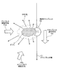
【解決手段】液体金属であるドロップレットDにプリパルスP1を照射した後にメインパルスP2を照射してEUV光を生成する極端紫外光源装置において、プリパルスP1をドロップレットD1に照射しドロップレットD1の一部を残してプリパルスレーザ光照射側の該ドロップレットD1空間外の異なる空間にプリプラズマ1の空間を生成するプリパルスレーザと、プリプラズマ1の空間にメインパルスP2を照射してEUV光を生成するメインパルスレーザと、を備える。
【選択図】 図1An extreme ultraviolet light source device capable of generating highly reliable extreme ultraviolet light that is stable over a long period of time while maintaining high conversion efficiency.
In an extreme ultraviolet light source device that generates EUV light by irradiating a main pulse P2 after irradiating a droplet D, which is a liquid metal, with a prepulse P1, the droplet D1 is irradiated with the prepulse P1. A pre-pulse laser that generates a space of the pre-plasma 1 in a different space outside the droplet D1 space on the pre-pulse laser light irradiation side while leaving a portion, and an EUV light is generated by irradiating the space of the pre-plasma 1 with the main pulse P2 A main pulse laser.
[Selection] Figure 1
Description
この発明は、液体金属のターゲットにプリパルスレーザ光を照射した後にメインパルスレーザ光を照射して極端紫外光を生成する極端紫外光源装置および極端紫外光生成方法に関するものである。 The present invention relates to an extreme ultraviolet light source device and an extreme ultraviolet light generation method for generating extreme ultraviolet light by irradiating a main pulse laser light after irradiating a liquid metal target with prepulse laser light.
近年、半導体プロセスの微細化に伴って光リソグラフィにおける微細化が急速に進展しており、次世代においては、70nm〜45nmの微細加工、さらには45nm以下の微細加工が要求されるようになる。このため、たとえば、32nm以下の微細加工の要求に応えるべく、波長13nm程度の極端紫外光(EUV)光源と縮小投影反射光学系とを組み合わせた露光装置の開発が期待されている。 In recent years, along with miniaturization of semiconductor processes, miniaturization in photolithography has rapidly progressed, and in the next generation, fine processing of 70 nm to 45 nm, and further, fine processing of 45 nm or less will be required. For this reason, for example, in order to meet the demand for fine processing of 32 nm or less, development of an exposure apparatus combining an extreme ultraviolet (EUV) light source having a wavelength of about 13 nm and a reduced projection reflection optical system is expected.
EUV光源としては、ターゲットにレーザビームを照射することによって生成されるプラズマを用いたLPP(Laser Produced Plasma:レーザ励起プラズマ)光源と、放電によって生成されるプラズマを用いたDPP(Discharge Produced Plasma)光源と、軌道放射光を用いたSR(Synchrotron Radiation)光源との3種類がある。これらのうち、LPP光源は、プラズマ密度を大きくできるので黒体輻射に近い極めて高い輝度が得られ、ターゲット物質を選択することにより、必要な波長帯のみの発光が可能であり、ほぼ等方的な角度分布をもつ点光源であるので、光源の周囲に電極等の構造物がなく、極めて大きな捕集立体角の確保が可能である等の利点を有することから、数十から数百ワット以上のパワーが要求されるEUVリソグラフィ用の光源として有力であると考えられている。 As the EUV light source, an LPP (Laser Produced Plasma) light source using plasma generated by irradiating a target with a laser beam, and a DPP (Discharge Produced Plasma) light source using plasma generated by discharge And SR (Synchrotron Radiation) light source using orbital radiation. Among these, since the LPP light source can increase the plasma density, extremely high luminance close to black body radiation can be obtained, and by selecting a target material, light emission only in a necessary wavelength band is possible, and isotropic. Because it is a point light source with a uniform angle distribution, there are no structures such as electrodes around the light source, and it has the advantage that it is possible to ensure a very large collection solid angle, so several tens to several hundred watts or more Therefore, it is considered to be a promising light source for EUV lithography that requires high power.
このLPP方式によるEUV光光源装置は、まず、真空チャンバ内に供給されるターゲット物質に対してレーザ光を照射することにより、ターゲット物質が励起してプラズマ化する。このプラズマから、EUV光を含む様々な波長成分が放射される。そこで、所望の波長成分、たとえば、13.5nmの波長を有する成分を選択的に反射するEUV集光ミラーを用いてEUV光が反射集光され、露光装置に入力される。EUV集光ミラーの反射面には、たとえば、モリブデン(Mo)の薄膜とシリコン(Si)の薄膜とを交互に積層した多層膜(Mo/Si多層膜)が形成されている。この多層膜は波長13.5nmのEUV光を高反射(約60%から70%)することができる。 In this EUV light source device using the LPP method, first, a target material supplied into a vacuum chamber is irradiated with laser light, whereby the target material is excited and turned into plasma. Various wavelength components including EUV light are radiated from this plasma. Therefore, EUV light is reflected and collected using an EUV collector mirror that selectively reflects a desired wavelength component, for example, a component having a wavelength of 13.5 nm, and is input to the exposure apparatus. On the reflective surface of the EUV collector mirror, for example, a multilayer film (Mo / Si multilayer film) in which molybdenum (Mo) thin films and silicon (Si) thin films are alternately laminated is formed. This multilayer film can highly reflect (about 60% to 70%) EUV light having a wavelength of 13.5 nm.
ここで、特許文献1には、固体ターゲットに予め窪みを設け、アブレーションレーザをこの窪みに向けて照射し、この窪みの内壁の表層部分を気化させ、さらにこの気化した物質に加熱用レーザを照射して高温プラズマ化し、変換効率の高い光源を実現している。なお、変換効率とは、ターゲットに照射されるレーザ光のパワーに対して、生成される所望の波長のEUV光のパワーの比をいう。この光源では、変換効率を高くすることができるが、一時的な極端紫外光の観察には適しているが、バルク材では、長時間にわたり同じ窪みを連続的に生成し、この窪みに固体ターゲットを連続的に供給するのは困難であり、長時間の安定した運転が必要とされる露光装置用光源として用いることは困難である。 Here, in Patent Document 1, a hollow is provided in advance in a solid target, an ablation laser is irradiated toward the hollow, a surface layer portion of the inner wall of the hollow is vaporized, and a heating laser is irradiated to the vaporized substance. As a result, the light source is converted into high-temperature plasma to realize a light source with high conversion efficiency. The conversion efficiency refers to the ratio of the power of the EUV light having a desired wavelength to be generated to the power of the laser light irradiated to the target. Although this light source can increase the conversion efficiency, it is suitable for temporary extreme ultraviolet observation, but the bulk material continuously generates the same depression over a long period of time, and a solid target is formed in this depression. Is difficult to supply continuously, and it is difficult to use as a light source for an exposure apparatus that requires stable operation for a long time.
また、特許文献2には、ノズルから圧力によって押し進められる常温において気体であるXeなどの希ガスで実現される気体の1次ターゲットに第1のエネルギーパルスを照射して2次ターゲットを生成し、所定時間を経て等方的に拡大された2次ターゲットに対して第2のエネルギーパルスを照射し、生成したプラズマから放射線を放出するようにしている。しかし、Xeターゲットのプラズマでは、必要とする13.5nmのEUV光の発光効率が低いことから、結果として変換効率(1%以下)が低く、露光装置用光源として用いることは困難である。
Further, in
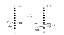
一方、特許文献3には、13.5nmのEUV光を効率よく発光することができるSnの液体ドロップレットを採用し、図14に示すように、プリパルスP300で液体のドロップレットであるターゲットC300を粉々に破壊して拡大させ、この拡大したターゲットC301にメインパルスP301を照射してEUV光を発生させるものが記載されている。この光源では、固体ではなくSnの液体のドロップレットを用いていることと、粉々に粉砕拡大したターゲットにメインパルスを照射することによりEUVの発光効率を高めたため、露光装置用光源として長時間、安定した運転が可能になり、ターゲットとして気体でなく液体金属を用いることによって変換効率の改善を図っている。
On the other hand,
しかしながら、液体金属のドロップレットにプリパルスを照射すると、ドロップレットは、ドロップレット進行軸から弾き飛ばされドロップレットが破壊し、プリパルスレーザの光軸方向にプラズマ、ドロップレットが気化したものおよび微小ドロップレットなどが拡大しながら飛散しデブリが多く発生する。そして、これらの拡大飛散したターゲットにメインパルスの照射することによっても、微小ドロップレットの径や量が大きい場合には、さらに多くのデブリが発生し、飛散する。この飛散したデブリは、周辺の光学素子、たとえばEUV集光ミラーなどの反射面を汚染または損傷することにより13.5nmのEUV光の反射率が短期間に低下するため、長期間にわたって信頼性の高い光源を実現することができないという問題点があった。 However, when a prepulse is applied to a liquid metal droplet, the droplet is blown off from the droplet traveling axis and the droplet is destroyed. As it expands, etc., it is scattered and a lot of debris is generated. Even when these enlarged and scattered targets are irradiated with the main pulse, if the diameter and amount of the minute droplets are large, more debris is generated and scattered. The scattered debris is less reliable for a long period of time because the reflectance of 13.5 nm EUV light decreases in a short time by contaminating or damaging the surrounding optical elements such as the EUV collector mirror. There was a problem that a high light source could not be realized.
なお、飛散した微小ドロップレット群は、中性粒子であるため、電磁界などの発生によって飛散を制御することができない。また、この飛散の位置と分布の制御が困難なことは、メインパルスのスポット径と一致させることも困難となり、上述したように、メインパルスに照射されずに、そのままデブリとして周囲に飛散するものが多くなっていた。 In addition, since the scattered fine droplet group is a neutral particle, the scattering cannot be controlled by generation of an electromagnetic field or the like. In addition, the difficulty in controlling the position and distribution of this scattering makes it difficult to match the spot diameter of the main pulse, and as described above, it is scattered as a debris as it is without being irradiated to the main pulse. There were many.
この発明は、上記に鑑みてなされたものであって、高い変換効率を維持しつつ、長期間にわたって安定した信頼性の高い極端紫外光を生成することができる極端紫外光源装置および極端紫外光生成方法を提供することを目的とする。 The present invention has been made in view of the above, and an extreme ultraviolet light source device and an extreme ultraviolet light generation capable of generating stable and highly reliable extreme ultraviolet light over a long period of time while maintaining high conversion efficiency It aims to provide a method.
上述した課題を解決し、目的を達成するために、この発明にかかる極端紫外光源装置は、ターゲットにプリパルスレーザ光を照射した後にメインパルスレーザ光を照射して極端紫外光を生成する極端紫外光源装置において、前記プリパルスレーザ光を前記ターゲットに照射し前記ターゲットの一部を残して前記プリパルスレーザ光照射側の該ターゲット空間外の異なる空間にプリプラズマを生成するプリパルスレーザ光源と、前記プリプラズマに前記メインパルスレーザ光を照射して前記極端紫外光を生成するメインパルスレーザ光源と、を備えたことを特徴とする。 In order to solve the above-described problems and achieve the object, the extreme ultraviolet light source device according to the present invention is an extreme ultraviolet light source that generates extreme ultraviolet light by irradiating a main pulse laser light after irradiating a target with prepulse laser light. In the apparatus, a prepulse laser light source that irradiates the target with the prepulse laser light and generates a preplasma in a different space outside the target space on the prepulse laser light irradiation side while leaving a part of the target; And a main pulse laser light source for generating the extreme ultraviolet light by irradiating the main pulse laser light.
また、この発明にかかる極端紫外光源装置は、上記の発明において、前記ターゲットは液滴であり、前記プリパルスレーザ光源は、前記液滴をプリパルスレーザ照射後においても、液滴として存在する程度のレーザ強度であることを特徴とする。 In the extreme ultraviolet light source device according to the present invention, in the above invention, the target is a droplet, and the prepulse laser light source is a laser that is present as a droplet even after the droplet is irradiated with the prepulse laser. It is characterized by strength.
また、この発明にかかる極端紫外光源装置は、上記の発明において、前記ターゲットは固体ターゲットであることを特徴とする。 In the extreme ultraviolet light source device according to the present invention as set forth in the invention described above, the target is a solid target.
また、この発明にかかる極端紫外光源装置は、上記の発明において、前記プリパルスレーザ光源は、前記ターゲットの一部にアブレーションが生じる程度のレーザ強度であることを特徴とする。 In the extreme ultraviolet light source device according to the present invention as set forth in the invention described above, the prepulse laser light source has a laser intensity at which ablation occurs in a part of the target.
また、この発明にかかる極端紫外光源装置は、上記の発明において、前記プリパルスレーザ光の照射強度は、107〜109W/cm2であることを特徴とする。 In the extreme ultraviolet light source device according to the present invention as set forth in the invention described above, the irradiation intensity of the prepulse laser light is 10 7 to 10 9 W / cm 2 .
また、この発明にかかる極端紫外光源装置は、上記の発明において、前記メインパルスレーザ光源は、前記プリプラズマのみに前記メインパルスレーザ光を照射することを特徴とする。 In the extreme ultraviolet light source device according to the present invention as set forth in the invention described above, the main pulse laser light source irradiates only the pre-plasma with the main pulse laser light.
また、この発明にかかる極端紫外光源装置は、上記の発明において、前記プリパルスレーザ光源は、前記ターゲットの進行軸と略一致し、前記ターゲットの進行方向と逆方向から前記ターゲットにプリパルスを照射し、前記ターゲットの進行方向に、前記液滴にプリパルスレーザ光照射後においても存在するターゲットおよび前記プリプラズマ内に残ったデブリの収容が可能な開口を有するキャッチャーを設けたことを特徴とする。 Further, in the extreme ultraviolet light source device according to the present invention, in the above invention, the prepulse laser light source substantially coincides with a traveling axis of the target and irradiates the target with a prepulse from a direction opposite to the traveling direction of the target. In the traveling direction of the target, a catcher having an opening capable of accommodating a target existing after the droplet is irradiated with prepulse laser light and debris remaining in the preplasma is provided.
また、この発明にかかる極端紫外光源装置は、上記の発明において、前記プリパルスレーザ光源は、ピコ秒以下の時間幅をもつパルスを生成するピコ秒パルスレーザであることを特徴とする。 In the extreme ultraviolet light source apparatus according to the present invention as set forth in the invention described above, the pre-pulse laser light source is a picosecond pulse laser that generates a pulse having a time width equal to or less than a picosecond.
また、この発明にかかる極端紫外光生成方法は、ターゲットにプリパルスレーザ光を照射した後にメインパルスレーザ光を照射して極端紫外光を生成する極端紫外光生成方法であって、前記プリパルスレーザ光を前記ターゲットに照射し前記ターゲットの一部を残して前記プリパルスレーザ光照射側の該ターゲット空間外の異なる空間にプリプラズマを生成するプリプラズマ生成ステップと、前記プリプラズマに前記メインパルスレーザ光を照射して前記極端紫外光を生成する極端紫外光生成ステップと、を含むことを特徴とする。 An extreme ultraviolet light generation method according to the present invention is an extreme ultraviolet light generation method for generating extreme ultraviolet light by irradiating a main pulse laser light after irradiating a target with prepulse laser light, the prepulse laser light being A pre-plasma generating step for generating a pre-plasma in a different space outside the target space on the pre-pulse laser beam irradiation side while irradiating the target and leaving a part of the target; and irradiating the pre-plasma with the main pulse laser beam And an extreme ultraviolet light generating step for generating the extreme ultraviolet light.
この発明によれば、プリパルスレーザ光源が、プリパルスレーザ光をターゲットに照射し前記ターゲットの一部を残して前記プリパルスレーザ光照射側の該ターゲット空間外の異なる空間にプリプラズマを生成し、メインパルスレーザ光源が、前記プリプラズマにメインパルスレーザ光を照射して極端紫外光を生成するようにし、デブリをプリプラズマのみから発生するようにしているため、デブリの発生が少なく、長期間にわたって安定した信頼性の高い極端紫外光光源および極端紫外光生成方法を実現できる。 According to the present invention, the prepulse laser light source irradiates the target with prepulse laser light, leaves a part of the target, generates preplasma in different spaces outside the target space on the prepulse laser light irradiation side, The laser light source emits main pulse laser light to the pre-plasma to generate extreme ultraviolet light, and debris is generated only from the pre-plasma. A highly reliable extreme ultraviolet light source and extreme ultraviolet light generation method can be realized.
以下、図面を参照して、この発明を実施するための形態である極端紫外光源装置について説明する。 Hereinafter, an extreme ultraviolet light source device that is an embodiment for carrying out the present invention will be described with reference to the drawings.
まず、図1および図2を参照して、この発明の一態様についての概念を説明する。図1において、液体金属であるSnのドロップレットDは、ターゲットとして、ドロップレット軸C1に沿ってノズルから放出される。所定位置に着いたドロップレットD1には、図1(a)に示すように、プリパルスレーザから照射されるプリパルスP1が照射され、図1(b)に示すように、ドロップレットD1は、プリパルスP1によるアブレーションによってプリプラズマ1を生成する。ここで、プリプラズマ1は、ドロップレットの照射表面付近の部分がEUV光を発光しない程度の弱いプラズマ状態、あるいは中性気体(蒸気)とこの弱いプラズマ状態との混合状態と推測される。以下の説明及び図面において、この弱いプラズマ状態、あるいは中性気体と弱いプラズマ状態との混合状態と推測される状態をプリプラズマと記述する。 First, the concept of one embodiment of the present invention will be described with reference to FIGS. In FIG. 1, a droplet D of Sn, which is a liquid metal, is emitted from a nozzle along a droplet axis C1 as a target. The droplet D1 arriving at a predetermined position is irradiated with a prepulse P1 emitted from a prepulse laser as shown in FIG. 1A, and the droplet D1 is irradiated with a prepulse P1 as shown in FIG. 1B. Pre-plasma 1 is generated by ablation by the above. Here, the pre-plasma 1 is presumed to be a weak plasma state in which the portion near the irradiation surface of the droplet does not emit EUV light, or a mixed state of neutral gas (vapor) and this weak plasma state. In the following description and drawings, this weak plasma state or a state presumed to be a mixed state of neutral gas and weak plasma state is described as pre-plasma.
そして、このプリプラズマ1の生成とともに、アブレーションしないドロップレットの一部である破壊されない残存ドロップレットD2が残る。ここで、残存ドロップレットD2は、ドロップレット軸C1から大きくずれず、プリプラズマ1は、プリパルスP1の照射方向に逆向きで生成され、残存ドロップレットD2の空間と、プリプラズマ1の空間とは分離された状態となる。プリパルスP1が照射された後の微小時間Δt後、図1(b)に示すように、メインパルスレーザから、このプリプラズマ1にのみメインパルスP2が照射され、13.5nmの所望のEUV光2が等方的に発光される。その後、図1(c)および図2に示すように、所望のEUV光2の生成後に残存ドロップレットD2は、略ドロップレット軸C1に沿ってドロップレット進行方向DAに移動する。
Then, along with the generation of the pre-plasma 1, there remains a non-destructed residual droplet D2, which is a part of the droplet that is not ablated. Here, the remaining droplet D2 is not greatly deviated from the droplet axis C1, and the pre-plasma 1 is generated in the opposite direction to the irradiation direction of the pre-pulse P1, and the space of the remaining droplet D2 and the space of the pre-plasma 1 are It becomes a separated state. After a minute time Δt after the irradiation with the pre-pulse P1, as shown in FIG. 1 (b), the main pulse P2 is irradiated only from the main pulse laser to the pre-plasma 1, and the desired
ここで、残存ドロップレットD2は、プリパルスP1によってドロップレットが破壊して、飛散が発生しておらず、しかもメインパルスP2がこの残存ドロップレットD2に照射されていないため、デブリが発生しない。さらに、メインパルスP2がプリプラズマ1の空間に照射されて、この照射空間からEUV光を発光する。その結果、プリプラズマ1の空間のみからデブリ3が発生するため、発生するデブリの量が極めて少なく、周辺の光学素子、たとえばEUV集光ミラーなどの反射面の汚染が極めて少なく、長期間にわたって安定した信頼性のある露光装置用の光源装置が実現される。
Here, since the droplet is destroyed by the pre-pulse P1, the remaining droplet D2 is not scattered, and the main pulse P2 is not irradiated to the remaining droplet D2, so that debris does not occur. Further, the main pulse P2 is applied to the space of the pre-plasma 1, and EUV light is emitted from this irradiation space. As a result, since the
なお、プリプラズマ1にのみにメインパルスP2を照射した場合であっても、図17に示した光源装置による変換効率と同等の変換効率を得ることを発明者らは発見した。この場合、プリパルスP1のレーザ強度は、1×10⁹W/cm2以下であり、所望のEUV光2を得るために、1×107W/cm2以上であることが必要であった。また、プリパルスレーザは波長1.064μmのYAGレーザ、メインパルスレーザは波長10.6μmのCO2レーザを用いており、繰り返し周波数は、7kHz以上である。したがって、ドロップレットDも、この繰り返し周波数に対応した間隔あるいはその倍数の間隔で同期して放出される。
The inventors have found that even when only the pre-plasma 1 is irradiated with the main pulse P2, the conversion efficiency equivalent to that of the light source device shown in FIG. 17 is obtained. In this case, the laser intensity of the pre-pulse P1 is 1 × 10 9 W / cm 2 or less, and in order to obtain the desired
ここで、プリパルスP1のドロップレットD1に対するスポット径は、ドロップレットD1の径以下であり、メインパルスP2のプリプラズマ1に対するスポット径は、プリプラズマ1の径と略同一にしている。また、プリパルスP1のプリパルス照射方向P1AとメインパルスP2のメインパルス照射方向P2Aとは異なる方向であるとともに、プリパルスP1およびメインパルスP2の集光位置は異なる。従来例(図17)と異なり、このメインパルスP2の集光位置はドロップレットD1のプリパルスレーザの入射側の手前の位置に発生するプリプラズマ1の中心付近となる。 Here, the spot diameter of the prepulse P1 with respect to the droplet D1 is equal to or smaller than the diameter of the droplet D1, and the spot diameter of the main pulse P2 with respect to the preplasma 1 is substantially the same as the diameter of the preplasma 1. Further, the prepulse irradiation direction P1A of the prepulse P1 and the main pulse irradiation direction P2A of the main pulse P2 are different directions, and the condensing positions of the prepulse P1 and the main pulse P2 are different. Unlike the conventional example (FIG. 17), the condensing position of the main pulse P2 is near the center of the pre-plasma 1 generated at a position before the incident side of the pre-pulse laser of the droplet D1.
なお、プリプラズマ1は、イオンを有するため、電磁界制御が可能であり、プリプラズマ1の空間の位置および分布を制御することができる。 Since the pre-plasma 1 has ions, the electromagnetic field can be controlled, and the position and distribution of the space of the pre-plasma 1 can be controlled.
(実施の形態1)
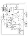
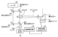
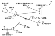
つぎに、図3を参照して、上述した概念を適用した極端紫外光源装置について説明する。図3において、この極端紫外光源装置は、SnのドロップレットDを図示しない真空チャンバ内に放出するノズル10と、この真空チャンバ内のドロップレットDに7kHz以上の繰り返し周波数で1.064μmのプリパルスP1を照射するYAGレーザであるプリパルスレーザ11と、この真空チャンバ内で発生したプリプラズマ1に7kHz以上でプリパルスP1と同じ繰り返し周波数で10.6μmのメインパルスP2をプリプラズマ1に照射するCO2レーザであるメインパルスレーザ21とを有する。プリパルスP1の強度は、1×10⁷W/cm2以上、1×109W/cm2以下である。このプリパルスP1の強度は、ドロップレットDの一部から、13.5nmの所望かつ十分なEUV光2を発生させることができるプリプラズマ1とドロップレットが破壊されない残存ドロップレットD2を生成することができる程度のものである。
(Embodiment 1)
Next, an extreme ultraviolet light source device to which the above-described concept is applied will be described with reference to FIG. In FIG. 3, this extreme ultraviolet light source device includes a
プリパルスレーザ11は、ミラー12および集光ミラー13を介して、プリパルスP1を、所定の位置に達したドロップレットD1に照射し、プリプラズマ1を残存ドロップレットD2の空間外に生成させる。
The
一方、メインパルスレーザ21は、ミラー22、軸外放物面の集光ミラー23、楕円面のEUV集光ミラー24の貫通孔24aを介して、プリパルスP1によって生成されたプリプラズマ1にのみ、メインパルスP2を照射し、EUV光2を生成させる。メインパルスP2は、最終的にダンパ25に吸収される。
On the other hand, the
楕円面のEUV集光ミラー24は、生成されたEUV光2を集光し、この集光されたEUV光は、図示しないチャンバ外の露光装置側へ入力される。
The elliptical
トリガ発生器31は、プリパルスレーザ11のプリパルスP1発生タイミング、メインパルスレーザ21のメインパルスP2発生タイミング、およびノズル10からのドロップレットDの放出タイミングを、メインコントローラ30の制御のもとに、調整して発生する。すなわち、プリパルスP1およびメインパルスP2の繰り返し周波数とドロップレットDの放出周波数とを一致させるとともに、ドロップレットD1の所定の空間位置でのプリパルスP1およびメインパルスP2の照射タイミングの同期をとる。
The
画像解析器34は、バックライト35によって照らされたドロップレットD1の反射光あるいはプリプラズマ1の発光をCCDカメラ33で受光し、この受光画像を解析する。集光位置コントローラ32は、画像解析器34の解析結果をもとに、集光ミラー13,23の集光位置および方向を制御する。
The
なお、残存ドロップレットD2は、ドロップレット進行方向DA先に設けられたデブリキャッチャー40によって回収される。
The remaining droplet D2 is collected by the
このような構成によって、滴下するドロップレットD1は、プリパルスP1が照射されることによって、ドロップレットD1のプリパルスの入射側の空間にプリプラズマ1を生成し、微小時間Δt後、このプリプラズマ1のみにメインパルスP2を照射することによって、EUV光2を生成し、EUV集光ミラー24を介してEUV光を外部に出力する。なお、プリパルスレーザとメインパルスレーザの遅延時間である微小時間ΔTは50ns〜100nsの範囲が最適であった。上述したように、残存ドロップレットD2にメインパルスP2を照射せず、プリプラズマ1から発生する僅かなデブリが発生するのみであるので、デブリによるEUV集光ミラー24の反射面などの光学素子への汚染が極端に少なくなり、長期間にわたって安定した信頼性のある光源が実現される。また、液体金属すなわちSnのドロップレットを用いており、さらに、プリプラズマ1に対して効率的にメインパルスP2が照射されるため、プリパルスによりドロップレット全体を破壊拡大したターゲットにメインパルスを照射した場合と同様の高い変換効率も実現される。
With such a configuration, the droplet D1 to be dropped is irradiated with the pre-pulse P1, thereby generating the pre-plasma 1 in the space on the incident side of the pre-pulse of the droplet D1, and only this pre-plasma 1 after a minute time Δt. By irradiating the main pulse P2, the
(実施の形態2)
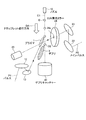
上述した実施の形態1では、プリパルスP1をドロップレット軸C1に略直交する方向から照射することを前提として説明したが、この実施の形態2では、図4に示すように、プリパルスP1をドロップレット軸C1に略沿った方向から照射するようにしている。
(Embodiment 2)
In the first embodiment described above, the prepulse P1 has been described on the premise that the prepulse P1 is irradiated from the direction substantially orthogonal to the droplet axis C1, but in the second embodiment, as shown in FIG. Irradiation is performed from a direction substantially along the axis C1.
この場合、メインパルスP2照射後、プリプラズマ1から生成されるデブリ3は、ドロップレット軸C1に沿って生成されるため、デブリキャッチャー40は、残存ドロップレットD2のみならず、プリプラズマ1から生成されるデブリ3も容易に回収することができる。この場合、デブリ3のドロップレット軸C1からの広がり具合をもとに、デブリキャッチャー40の開口を決定すればよい。これによって、デブリの飛散量を最小限に抑えることができる。なお、図4に示すように、デブリの飛散方向すなわちドロップレットDの進行方向と、垂直な方向にEUV集光ミラー24が配置されるため、特にEUV集光ミラー24の反射面のデブリ汚染を効果的に防ぐことができる。
In this case, the
(プリパルスの位置制御例)
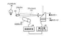
ここで、プリパルスレーザ11から出力されるプリパルスP1の位置制御について説明する。図5に示すように、CCDカメラ33が、プリプラズマ1の発光を撮像し、この発光位置をプリパルスP1の焦点位置として決定すればよい。すなわち、画像解析器34によってプリプラズマ1の発光位置を特定し、集光位置コントローラ32は、この特定した位置がプリパルスP1の所望の集光位置となるように、集光ミラー13の3軸ステージ14を制御することによって、プリパルスP1の位置制御がなされる。
(Prepulse position control example)
Here, the position control of the prepulse P1 output from the
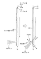
また、図6に示すように、レーザ干渉計を用いてプリパルスP1の位置制御を行うようにしてもよい。この実施例ではマッハツェンダ干渉計採用している。すなわち、光源としてのレーザ50とレンズ33aとの間に、部分反射ミラーM1、全反射ミラーM2、全反射ミラーM3、および部分反射ミラーM4を設け、レーザ50、部分反射ミラーM1、全反射ミラーM2、部分反射ミラーM4を通る一方の光路と、レーザ50、部分反射ミラーM2、全反射ミラーM3、部分反射ミラーM4を通る他方の光路とを形成し、この2つの光路間の干渉を計測する。そして、一方の光路、すなわち全反射ミラーM2と部分反射ミラーM4との間に、プリプラズマ1が配置するようにレーザ干渉計を配置する。
Further, as shown in FIG. 6, the position control of the pre-pulse P1 may be performed using a laser interferometer. In this embodiment, a Mach-Zehnder interferometer is used. That is, the partial reflection mirror M1, the total reflection mirror M2, the total reflection mirror M3, and the partial reflection mirror M4 are provided between the
CCDカメラ33は、レンズ33aを介してプリプラズマ1空間が介在することによる干渉縞を撮像し、画像解析器34は、この撮像された干渉縞を解析し、集光位置コントローラ32は、プリプラズマ1空間の密度に応じた干渉縞をもとに、プリプラズマ1の密度がメインパルスP2によりEUV発光の効率が最適となる密度の値となる位置をプリパルスP1の焦点位置として特定し、この特定した位置がプリパルスP1の所望の焦点位置となるように、集光ミラー13の3軸ステージ14を制御することによって、プリパルスP1の焦点位置の位置制御を行う。なお、メインレーザがCO2レーザの場合のプリプラズマの密度が約1018個/ccの密度であれば、高い変換効率を得ることができる。
The
なお、図6に示すように、干渉計の光源は、レーザであることが好ましい。取得される画像は、プリプラズマ1の密度に依存した屈折率の空間分布で上述したように干渉縞として観測される。ここで、干渉計の光源の波長を短くすれば、屈折率の変化に対するフリンジ数が密になるため、一層、薄い密度の状態のプラズマも計測可能になるからである。 As shown in FIG. 6, the light source of the interferometer is preferably a laser. The acquired image is observed as interference fringes as described above in the spatial distribution of the refractive index depending on the density of the pre-plasma 1. Here, if the wavelength of the light source of the interferometer is shortened, the fringe number with respect to the change in the refractive index becomes dense, so that plasma with a lower density can be measured.
さらに、図7に示すように、プローブレーザ51をプリプラズマ1に照射し、その散乱光をCCDカメラ33によって観測してプリパルスP1の集光位置を制御するようにしてもよい。この場合、プローブレーザ51としては、波長が短く、強度が強い程、プリプラズマ1からの散乱光の強度も強くなるので、CCDカメラ33で検出する信号強度が上がり、S/N比の高い画像を得ることができる。このようにしてCCDカメラ33が得た画像をもとに、画像解析器34がプリプラズマ1の位置および分布を解析し、集光位置コントローラ32は、この解析結果をもとに、プリパルスP1の焦点位置を特定し、この特定した焦点位置が所望の焦点位置となるように、集光ミラー13の3軸ステージ14を制御することによって、プリパルスP1の焦点位置の位置制御を行う。
Furthermore, as shown in FIG. 7, the pre-plasma 1 may be irradiated with the
なお、プリパルスP1は、7から100kHz以上の繰り返し周波数で照射されている場合、その繰り返される全ての画像を解析して位置制御することは、現実的ではない。実際には、数ms〜数sにわたった平均値を3軸ステージ14にフィードバックして位置制御を行うようにしてもよい。
When the prepulse P1 is irradiated at a repetition frequency of 7 to 100 kHz or more, it is not realistic to control the position by analyzing all the repeated images. Actually, an average value over several ms to several s may be fed back to the three-
また、プリパルスP1の位置制御を行う場合、図5〜図7では、1つのCCDカメラ33を用いるようにしていたが、プリパルスP1の焦点位置は3次元位置であるため、CCDカメラは少なくとも2つ必要になる。
Further, when performing the position control of the prepulse P1, in FIG. 5 to FIG. 7, one
なお、図5〜図7の実施例では、プリパルスレーザの集光光学系として、軸外放物面ミラーを使用しているが、この例に限定されることなく、集光レンズを使用して、集光レンズの手前または後の光路中に高反射ミラーを配置して、この高反射ミラーを3軸ステージに設置して、プリパルスレーザの焦点の位置を制御してもよい。 In the embodiments of FIGS. 5 to 7, an off-axis paraboloidal mirror is used as the condensing optical system of the prepulse laser. However, the present invention is not limited to this example, and a condensing lens is used. Alternatively, a high reflection mirror may be arranged in the optical path before or after the condenser lens, and this high reflection mirror may be installed on the three-axis stage to control the focal position of the prepulse laser.
(タイミング制御例)
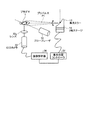
つぎに、ドロップレットD、プリパルスP1、およびメインパルスP2のタイミング制御について説明する。図8は、タイミング制御系の構成を示すブロック図である。図8において、ノズル10には、液体金属を液滴として放出するためのピエゾ素子61が設けられ、このピエゾ素子61は、ピエゾコントローラ60を介してメインコントローラ30に接続され、ドロップレットDの放出タイミングが制御される。ピエゾ素子61は、ノズル10の先端をドロップレット進行方向DAに振動させることによってドロップレットDを所定の周期で放出する。その他の構成は、図3に示した構成と同じであり、同一部分には同一符号を付している。なお、CCDカメラ33および画像解析器34は、プリパルスP1の監視系を構成しているが、さらにCCDカメラ53および画像解析器54は、メインパルスP2の監視系を構成している。
(Timing control example)
Next, timing control of the droplet D, the pre-pulse P1, and the main pulse P2 will be described. FIG. 8 is a block diagram showing the configuration of the timing control system. In FIG. 8, the
まず、時刻T=0において、ピエゾコントローラ60からピエゾ素子61にドロップレットD放出の制御信号が伝達され、ドロップレットDが位置f0から放出される。このドロップレットDは、時刻T=0から所定時間ΔT1だけ遅れてプリパルスP1の焦点位置f1に到達する。ここで、この瞬間を狙ってプリパルスP1をドロップレットDに照射するように、トリガ発生器31aを制御すればよい。
First, at time T = 0, a droplet D emission control signal is transmitted from the
しかし、ドロップレットDがプリパルスP1の焦点位置f1に常に同じ時間間隔で遅れて到達するとは限らない。これは、ドロップレットDそのものの不安定性であったり、図示しないチャンバなどの構造物の熱変形等に起因する比較的長時間にわたる変形などが生じるからである。すなわち、種々の起因によって、ドロップレットDの放出位置f0からプリパルスP1の焦点位置f1に到達するまでの時刻は変化する可能性がある。このために、ドロップレットDのプリパルスP1の焦点位置f1への到達を監視し、ドロップレットDに対してプリパルスP1の焦点位置でプリパルスP1を照射できるようにプリパルスP1の照射タイミングを制御する必要がある。 However, the droplet D does not always arrive at the focal position f1 of the pre-pulse P1 with a delay at the same time interval. This is because the droplet D itself is unstable or deforms over a relatively long time due to thermal deformation of a structure such as a chamber (not shown). That is, the time from the droplet D emission position f0 to the focal position f1 of the pre-pulse P1 may change due to various causes. Therefore, it is necessary to monitor the arrival of the prepulse P1 of the droplet D at the focal position f1 and to control the irradiation timing of the prepulse P1 so that the droplet D can be irradiated with the prepulse P1 at the focal position of the prepulse P1. is there.
このため、CCDカメラ33で、プリパルスP1がドロップレットDに照射された際のプラズマ発光の画像を取得し、このプラズマ発光が常に略同じ強度で検出されるように、トリガ発生器31aを介してプリパルスP1の発振タイミングを変化させている。画像解析器34は、CCDカメラ33から送られた画像をもとにプラズマ発光強度を分析し、予め記録してある、良好なタイミングでのプラズマ発光強度と比較し、プリパルスP1の照射タイミングが適正であるか否かを判断する。メインコントローラ30は、この照射タイミングの判断結果をもとに、トリガ発生器31aのタイミングを変化させ、プリパルスP1の照射タイミングを変化させ、適正な照射タイミングとなるように制御している。
Therefore, the
同様にして、時刻T=ΔT2後におけるドロップレットDから発生したプリプラズマ1の発光をCCDカメラ53で取得し、画像解析器54によるプラズマ発光強度の判断結果をもとに、メインコントローラ30がトリガ発生器31bを介してメインパルスP2の照射タイミングを制御する。なお、メインパルスP2の場合、CCDカメラ53がEUV光の強度を直接検出してもよい。
Similarly, the emission of the pre-plasma 1 generated from the droplet D after time T = ΔT2 is acquired by the
なお、上述した実施の形態では、Snの液体金属のドロップレットを例にあげて説明したが、これに限らず、液体金属のドロップレットであればよい。また、照射するプリパルスレーザ11は1.064μmのYAGレーザ、メインパルスレーザ21を10.6μmのCO2レーザとして説明したが、ドロップレットから所望のEUV光を発することができる照射レーザであればよい。
In the above-described embodiment, the description has been given by taking the liquid metal droplets of Sn as an example. However, the present invention is not limited to this, and any liquid metal droplets may be used. The
(実施の形態3)
上述した実施の形態1,2では、ターゲットとして液体ターゲットであるドロップレットを用いていたが、この実施の形態3では、ターゲットとして固体ターゲットを用いるようにしている。
(Embodiment 3)
In
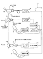
図9は、固体ターゲットとして、ワイヤ状ターゲットを用いた場合のEUV光発生の動作状態を示す図である。ワイヤ状ターゲット100は、強度の強いピアノ線(高炭素鋼の鋼線)である芯材101にSnのターゲット材102をコートしたものである。このターゲット材102は、溶融Sn金属浴中に、芯材101を浸積して溶融めっきによってSn金属をコートしてもよいし、Sn金属の粉体を吹き付けて芯材101にSn金属を塗布するようにしてもよいし、真空蒸着によってSn金属を芯材101にコートするようにしてもよい。
FIG. 9 is a diagram illustrating an operation state of EUV light generation when a wire target is used as the solid target. The wire-
ワイヤ状ターゲット100は、ドロップレットDのドロップレット軸C1と同様に、ターゲット軸C10を一方向に移動し、所定周波数でプリパルスP1が照射される(図9(a))。その後、プリパルスP1が照射されたターゲット材102の一部はプリプラズマ1を生成し、このプリプラズマ1にメインパルスP2が所定周波数で照射されることによって強いプラズマを発生し、EUV光2が発生する(図9(b))。
Similar to the droplet axis C1 of the droplet D, the
このワイヤ状ターゲット100は、予めワイヤ状ターゲット100が巻き取られたドラムから駆動機構によって繰り出され、他のドラムによって、芯材101上にターゲット材102が残存したワイヤ状ターゲット100が巻き取られるようにして、使い捨てるようにしている。
The wire-
なお、ワイヤ状ターゲット100をループ状にし、再利用するようにしてもよい。この場合、残存したワイヤ状ターゲット100に対し、冷却機能によって高温化したターゲット材101を冷却し、その後、再生機構によってターゲット材102を芯材101に再コートあるいは補充コートして新たなワイヤ状ターゲット100に再生する。
The
このワイヤ状ターゲット100の場合、デブリが固体→液体→気体に変化するため、ドロップレットDの場合に比して、熱(固体→液体の潜熱)が必要となり、中性粒子の発生量が少なくなる。また、このワイヤ状ターゲット100によって生じたプリプラズマ1は、ドロップレットDによって生じたプリプラズマ1に比して、密度状態の最適化が容易となり、変換効率(CE)を高めることができる。
In the case of this wire-
(実施の形態3の変形例1)
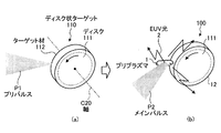
この変形例1では、ワイヤ状ターゲット100に替えて、ディスク状ターゲット110をターゲットとして用いている。図10に示すように、ディスク状ターゲット110は、ディスク111の周縁にSnのターゲット材112がコートされている。ディスク状ターゲット110が軸C20を中心に回転する状態で、ターゲット部材112に対して外径方向から所定周波数でプリパルスP1が照射されると(図10(a))、プリプラズマ1が発生し、このプリプラズマ1に対して所定周波数でメインパルスP2を照射することによって強いプラズマを発生し、EUV光2を発生する(図10(b))。
(Modification 1 of Embodiment 3)
In the first modification, a disk-shaped
この場合、プリパルスP1が照射されるディスク状ターゲット110の周縁上の軌跡を螺旋状とすることによって比較的長いEUV光2の発光が可能となる。もちろん、冷却機構と再生機構とをもちいてターゲット材112を再生することにより、EUV光2の連続発光が可能となる。
In this case, relatively
この変形例1では、ディスク状ターゲット110の場合、デブリが固体→液体→気体に変化するため、ドロップレットDの場合に比して、熱(固体→液体の潜熱)が必要となり、中性粒子の発生量が少なくなる。また、このディスク状ターゲット110によって生じたプリプラズマ1は、ワイヤ状ターゲット100によって生じたプリプラズマ1に比して、密度状態の最適化が容易となり、変換効率(CE)を高めることができる。
In the first modification, since the debris changes from solid to liquid to gas in the case of the disk-shaped
(実施の形態3の変形例2)
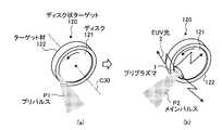
この変形例2では、変形例1と同様なディスク状をなすディスク状ターゲット120が用いられるが、Snのターゲット材122が、ディスク121の周縁ではなく、ディスク121の一側面の最外周近傍にリング状にコートされている。ディスク状ターゲット120が軸C30を中心に回転する状態で、ターゲット材122に対して略軸C30方向から所定周波数でプリパルスP1が照射されると(図11(a))、プリプラズマ1が発生し、このプリプラズマ1に対して所定周波数でメインパルスP2を照射することによって強いプラズマを発生し、EUV光2を発生する(図11(b))。
(
In the second modification, a disk-shaped
この場合、プリパルスP1が照射されるターゲット材122上の軌跡を渦巻き状とすることによって比較的長いEUV光2の発光が可能となる。もちろん、冷却機構と再生機構とをもちいてターゲット材122を再生することにより、EUV光2の連続発光が可能となる。
In this case, a relatively
この変形例2では、ディスク状ターゲット120の場合、デブリが固体→液体→気体に変化するため、ドロップレットDの場合に比して、熱(固体→液体の潜熱)が必要となり、中性粒子の発生量が少なくなる。また、このディスク状ターゲット120によって生じたプリプラズマ1は、ワイヤ状ターゲット100によって生じたプリプラズマ1に比して、密度状態の最適化が容易となり、変換効率(CE)を高めることができる。
In this modified example 2, in the case of the disk-shaped
(実施の形態3の変形例3)
この変形例3では、固体ターゲットしてテープターゲット130を用いている。このテープターゲット130は、図12に示すように、テープ状の芯材131の幅広の一側面にSnのターゲット材132がコートされている。テープターゲット130がターゲット軸C40の方向に移動する状態で、ターゲット材132の面に略垂直な方向から所定周波数でプリパルスP1が照射されると(図12(a))、プリプラズマ1が発生し、このプリプラズマ1に対して所定周波数でメインパルスP2を照射することによって強いプラズマを発生し、EUV光2を発生する(図12(b))。
(
In
この場合、テープターゲット130が使い捨てである場合、テープターゲット130をループ状に移動させ、プリパルスP1が照射されるターゲット材132上の軌跡が順次、ターゲット軸C40に垂直な方向にシフトさせることによって比較的長いEUV光2の発光が可能となる。もちろん、テープターゲット130をループ状にするとともに、冷却機構と再生機構とをもちいてターゲット材132を再生することにより、EUV光2の連続発光が可能となる。
In this case, when the
この変形例3では、テープターゲット130の場合、デブリが固体→液体→気体に変化するため、ドロップレットDの場合に比して、熱(固体→液体の潜熱)が必要となり、中性粒子の発生量が少なくなる。また、このテープターゲット130によって生じたプリプラズマ1は、ワイヤ状ターゲット100によって生じたプリプラズマ1に比して、密度状態の最適化が容易となり、変換効率(CE)を高めることができる。
In this modified example 3, in the case of the
(実施の形態3の変形例4)
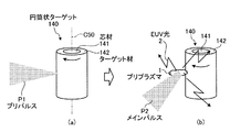
この変形例4では、固体ターゲットして円筒状ターゲット140を用いている。この円筒状ターゲット140は、図13に示すように、円筒状の芯材141の周面にSnのターゲット材142がコートされている。円筒状ターゲット140がターゲット軸C50を中心に回転した状態で、ターゲット材142の面に略垂直な方向から所定周波数でプリパルスP1が照射されると(図13(a))、プリプラズマ1が発生し、このプリプラズマ1に対して所定周波数でメインパルスP2を照射することによって強いプラズマを発生し、EUV光2を発生する(図13(b))。
(Modification 4 of Embodiment 3)
In this modification 4, a
この場合、プリパルスP1が照射されるターゲット材142上の軌跡を螺旋状とすることによって比較的長いEUV光2の発光が可能となる。もちろん、冷却機構と再生機構とをもちいてターゲット材132を再生することにより、EUV光2の連続発光が可能となる。
In this case, a relatively
この変形例4では、円筒状ターゲット140の場合、デブリが固体→液体→気体に変化するため、ドロップレットDの場合に比して、熱(固体→液体の潜熱)が必要となり、中性粒子の発生量が少なくなる。また、この円筒状ターゲット140によって生じたプリプラズマ1は、ワイヤ状ターゲット100によって生じたプリプラズマ1に比して、密度状態の最適化が容易となり、変換効率(CE)を高めることができる。
In the fourth modification, since debris changes from solid to liquid to gas in the case of the
(実施の形態3の変形例5)
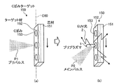
この変形例5では、固体ターゲットして、くぼみをもつくぼみターゲット150を用いている。このくぼみターゲット150は、図14に示すように、図12に示したテープターゲット130の表面側にくぼみ153を設けたものである。すなわち、くぼみターゲット150は、テープ状の芯材150の幅広の一側面に、表面側にくぼみ153が形成されたSnのターゲット材152がコートされている。このくぼみ153は、ターゲット軸C60方向に配列される。ターゲット材152上のくぼみ153は、テープ状のターゲット材152にくぼみ153が形成されているが、芯材151のターゲット材152が形成される面にくぼみを設け、このくぼみを含めてターゲット材152をコートすることによってくぼみ153を形成するようにしてもよい。
(Modification 5 of Embodiment 3)
In this modified example 5, the
くぼみターゲット150がターゲット軸C60方向に移動した状態で、ターゲット材152の面に略垂直な方向から、くぼみ153の位置に同期した所定周波数でプリパルスP1が照射されると(図14(a))、プリプラズマ1がくぼみ153から発生し、このプリプラズマ1に対して所定周波数でメインパルスP2を照射することによって強いプラズマを発生し、EUV光2を発生する(図14(b))。
When the
この変形例5では、くぼみターゲット150の場合、デブリが固体→液体→気体に変化するため、ドロップレットDの場合に比して、熱(固体→液体の潜熱)が必要となり、中性粒子の発生量が少なくなる。また、このくぼみターゲット150によって生じたプリプラズマ1は、テープターゲット130によって生じたプリプラズマ1に比して、密度状態の最適化が容易となり、変換効率(CE)を高めることができる。
In this modified example 5, since the debris changes from solid to liquid to gas in the case of the
なお、変形例5に示したくぼみ153は、上述した実施の形態3、実施の形態3の変形例1〜変形例4のそれぞれに適用可能である。このくぼみ153の形成によって、さらに高密度のプリプラズマ1の発生が可能となり、変換効率(CE)をさらに高めることができる。
The
また、変形例1〜5では、すべてをSn材で形成するようにしてもよい。たとえば、変形例1では、ディスク状ターゲット110全てをSnで形成されるようにしてもよい。
Moreover, in the modifications 1-5, you may make it form all by Sn material. For example, in Modification 1, all of the disk-shaped
(実施の形態4)
つぎに、この発明の実施の形態4について説明する。この実施の形態4では、図3に示したプリパルスレーザ11として、パルス時間幅がピコ秒以下となるパルスを出力するピコ秒パルスレーザを用いている。ここで、パルス時間幅Tがピコ秒以下のパルスを出力するピコ秒パルスレーザとは、パルス幅Tが1ns未満(T<1ns)のパルスレーザを示す。
(Embodiment 4)
Next, a fourth embodiment of the present invention will be described. In the fourth embodiment, as the
図15は、この発明の実施の形態4であるプリパルスレーザの構成を示す模式図である。図15において、このプリパルスレーザ11Aは、自己モード同期チタンサファイヤレーザである。このプリパルスレーザ11Aは、対向する高反射ミラー201,202間にレーザ媒質としてのチタンサファイヤ結晶203を設け、励起光源200が発する励起光LAが高反射ミラー201を介してチタンサファイヤ結晶203に入力される。励起光源200は、半導体レーザ励起Nd:YVO4あるいは半導体励起Nd:YAGの第2高調波(532nm)を励起光LAとして出力する。チタンサファイヤ結晶203は、励起光LAによって光励起され、たとえば800nmの光を発する。なお、高反射ミラー201は、励起光LAを透過させ、チタンサファイヤ結晶203から発する光を高反射する。一方、高反射ミラー202は、チタンサファイヤ結晶203から発する光を高反射する。
FIG. 15 is a schematic diagram showing a configuration of a prepulse laser according to the fourth embodiment of the present invention. In FIG. 15, the
半導体可飽和吸収ミラー205と出力結合ミラー208とは、レーザ共振器を形成する。高反射ミラー201によって反射された光は、凹面高反射ミラー204によって半導体可飽和吸収ミラー205に収束される。一方、高反射ミラー202によって反射された光は、プリズム206,207を介して出力結合ミラー208に導かれる。出力結合ミラー205は、レーザ共振器内の一部の光をプリパルスP1として外部出力する。
The semiconductor
励起光源200から高反射ミラー201を介して励起光LAがチタンサファイヤ結晶203に照射されると、半導体可飽和吸収ミラー205の可飽和吸収によってレーザ共振器内の縦モードがモード同期して発振し、チタンサファイヤ結晶203内に蓄積された反転分布エネルギーを短時間(ピコ秒)内に集中した光パルス(プリパルスP1)として出力結合ミラー208から出力される。
When the excitation light LA is irradiated onto the
このピコ秒以下の時間幅のプリパルスP1が、ドロップレットDなどのターゲットに照射されると、プリパルスP1の時間幅がピコ秒以下という極めて短い時間であるため、ターゲットの薄い表面のみをプリプラズマ化することになる。このため、ドロップレットDの場合、ターゲットが破壊されにくくなり、ターゲットの飛沫やデブリが減少することになる。また、ターゲットが固体ターゲットである場合も、ターゲット内部の破損を防止することができるとともに、ターゲットの飛沫やデブリが減少することになる。さらに、ピコ秒以下という時間幅が短いパルスが生成されるため、このパルスのピークパワーが高くなり、エネルギーの低いパルスであってもプリプラズマを発生させることができ、装置の小型化を促進することができる。 When the pre-pulse P1 having a time width of less than picosecond is irradiated onto a target such as the droplet D, the time width of the pre-pulse P1 is an extremely short time of less than picosecond, so that only the thin surface of the target is converted into pre-plasma. Will do. For this reason, in the case of the droplet D, it becomes difficult to destroy the target, and the splash and debris of the target are reduced. Further, even when the target is a solid target, damage to the inside of the target can be prevented, and splashes and debris of the target are reduced. Furthermore, since a pulse with a short time width of picoseconds or less is generated, the peak power of this pulse is increased, and a pre-plasma can be generated even with a pulse having a low energy, thereby promoting downsizing of the apparatus. be able to.
(実施の形態4の変形例1)
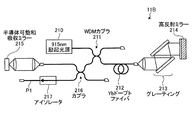
なお、ファイバレーザを用いてもピコ秒以下の時間幅をもったプリパルスP1を生成することもできる。図16は、この発明の実施の形態4の変形例1であるプリパルスレーザの構成を示す模式図である。このプリパルスレーザ11Bは、増幅媒体であるYbドープトファイバ212の一端に光学系を介して設けられた半導体可飽和吸収ミラー215と、他端にグレーティング213を介して設けられた高反射ミラー214とを有し、半導体可飽和吸収ミラーと高反射ミラー214との間でレーザ共振器が形成される。Ybドープトファイバ212には、WDMカプラ211を介して、915nm励起光源210から出力された915nmの励起光が入力される。Ybドープトファイバ212は、入力された915nmの光に励起されて980nmの光を出力する。この980nmの光は、グレーティング213を介して波長選択が行われつつ、半導体可飽和吸収ミラー215によってレーザ共振器内の縦モードがモード同期し、このモード同期したピコ秒パルスがカプラ216およびアイソレータ217を介し、プリパルスP1として出力される。
(Modification 1 of Embodiment 4)
Even if a fiber laser is used, the pre-pulse P1 having a time width of picosecond or less can be generated. FIG. 16 is a schematic diagram showing a configuration of a prepulse laser that is a first modification of the fourth embodiment of the present invention. This
この変形例1では、実施の形態4と同様のピコ秒パルスによる作用効果を奏するとともに、プリパルスP1が光ファイバを用いて導入することができるため、ターゲットに対してプリパルスP1を容易かつ高精度に照射することができる。また、ファイバレーザの横モード品質を示すM2の値が、1.2程度であるため、集光性能が高く、小さなターゲットであってもプリパルスP1を高精度に集光して照射することができる。 In the first modification, the same effect as that of the fourth embodiment is achieved by the picosecond pulse, and the prepulse P1 can be introduced using an optical fiber, so that the prepulse P1 can be easily and highly accurately applied to the target. Can be irradiated. Further, since the value of M 2 indicating the transverse mode quality of the fiber laser is about 1.2, the light condensing performance is high, and even with a small target, the prepulse P1 can be condensed and irradiated with high accuracy. it can.
なお、ピコ秒以下のプリパルスP1のパルスエネルギーが小さい場合には、再生増幅器によって増幅するようにしてもよい。さらに、パルス時間幅がフェムト秒となるパルスを出力するフェムト秒レーザを適用しても、同様な効果を得ることができる。 When the pulse energy of the pre-pulse P1 of picosecond or less is small, it may be amplified by a regenerative amplifier. Furthermore, even if a femtosecond laser that outputs a pulse having a pulse time width of femtosecond is applied, the same effect can be obtained.
また、プリパルスP1の波長は、短くなればなるほど、ターゲットであるSnの吸収率が高くなる。このため、プリパルスP1の波長は、短い方が好ましい。たとえば、プリパルスレーザ11として、Nd:YAGレーザを用いる場合、Nd:YAGレーザの波長=1064nm→この2倍高調波=532nm→この3倍高調波=355nm→この4倍高調波=266nmの順に、Snの吸収率は高くなり、短い波長のプリパルスP1とすることによって、高密度のプリプラズマを発生することができ、変換効率(CE)を高めることができる。
Moreover, the shorter the wavelength of the pre-pulse P1, the higher the absorption rate of the target Sn. For this reason, it is preferable that the wavelength of the pre-pulse P1 is shorter. For example, when an Nd: YAG laser is used as the
なお、上述した全ての実施の形態および全ての変形例は、適宜組合せが可能である。 It should be noted that all the embodiments described above and all the modifications can be combined as appropriate.
1 プリプラズマ
2 EUV光
3 デブリ
10 ノズル
11,11A,11B プリパルスレーザ
12,22 ミラー
13,23 集光ミラー
21 メインパルスレーザ
24 EUV集光ミラー
24a 貫通孔
25 ダンパ
30 メインコントローラ
31 トリガ発生器
32 集光位置コントローラ
33 CCDカメラ
34 画像解析器
35 バックライト
40 デブリキャッチャー
100 ワイヤ状ターゲット
101,131,141,151 芯材
102,112,122,132,142,152 ターゲット材
111,121 ディスク
110,120 ディスク状ターゲット
130 テープターゲット
140 円筒状ターゲット
150 くぼみターゲット
153 くぼみ
200 励起光源
201,202,214 高反射ミラー
203 チタンサファイアヤ結晶
204 凹面高反射ミラー
205,215 半導体可飽和吸収ミラー
206,207 プリズム
208 出力結合ミラー
210 915nm励起光源
211 WDMカプラ
212 Ybドープトファイバ
213 グレーティング
216 カプラ
217 アイソレータ
C1 ドロップレット軸
C10,C40,C50,C60 ターゲット軸
C20,C30 軸
D,D1 ドロップレット
D2 残存ドロップレット
P1 プリパルス
P2 メインパルス
DESCRIPTION OF SYMBOLS 1
Claims (9)
前記プリパルスレーザ光を前記ターゲットに照射し前記ターゲットの一部を残して前記プリパルスレーザ光照射側の該ターゲット空間外の異なる空間にプリプラズマを生成するプリパルスレーザ光源と、
前記プリプラズマに前記メインパルスレーザ光を照射して前記極端紫外光を生成するメインパルスレーザ光源と、
を備えたことを特徴とする極端紫外光源装置。 In an extreme ultraviolet light source device that generates extreme ultraviolet light by irradiating a main pulse laser light after irradiating a target with pre-pulse laser light,
A prepulse laser light source that irradiates the target with the prepulse laser light and generates a preplasma in a different space outside the target space on the prepulse laser light irradiation side, leaving a part of the target;
A main pulse laser light source that generates the extreme ultraviolet light by irradiating the pre-plasma with the main pulse laser light;
An extreme ultraviolet light source device characterized by comprising:
前記プリパルスレーザ光源は、前記液滴をプリパルスレーザ照射後においても、液滴として存在する程度のレーザ強度であることを特徴とする請求項1に記載の極端紫外光源装置。 The target is a droplet;
The extreme ultraviolet light source device according to claim 1, wherein the prepulse laser light source has a laser intensity enough to exist as a droplet even after the droplet is irradiated with the prepulse laser.
固体ターゲットであることを特徴とする請求項1に記載の極端紫外光源装置。 The target is
The extreme ultraviolet light source device according to claim 1, wherein the extreme ultraviolet light source device is a solid target.
前記ターゲットの進行方向に、前記液滴にプリパルスレーザ光照射後においても存在するターゲットおよび前記プリプラズマ内に残ったデブリの収容が可能な開口を有するキャッチャーを設けたことを特徴とする請求項2または3に記載の極端紫外光源装置。 The prepulse laser light source substantially coincides with the traveling axis of the target, irradiates the target with a prepulse from a direction opposite to the traveling direction of the target,
3. A catcher having an opening capable of accommodating a target that exists even after irradiation of a prepulse laser beam on the droplet and a debris remaining in the preplasma is provided in the traveling direction of the target. Or the extreme ultraviolet light source device according to 3;
前記プリパルスレーザ光を前記ターゲットに照射し前記ターゲットの一部を残して前記プリパルスレーザ光照射側の該ターゲット空間外の異なる空間にプリプラズマを生成するプリプラズマ生成ステップと、
前記プリプラズマに前記メインパルスレーザ光を照射して前記極端紫外光を生成する極端紫外光生成ステップと、
を含むことを特徴とする極端紫外光生成方法。 An extreme ultraviolet light generation method for generating extreme ultraviolet light by irradiating a main pulse laser light after irradiating a target with pre-pulse laser light,
A pre-plasma generating step of generating pre-plasma in a different space outside the target space on the pre-pulse laser beam irradiation side while irradiating the target with the pre-pulse laser beam and leaving a part of the target
An extreme ultraviolet light generation step of generating the extreme ultraviolet light by irradiating the pre-plasma with the main pulse laser beam;
An extreme ultraviolet light generation method comprising:
Priority Applications (4)
| Application Number | Priority Date | Filing Date | Title |
|---|---|---|---|
| JP2009212884A JP2010103499A (en) | 2008-09-29 | 2009-09-15 | Extreme ultraviolet light source apparatus and method for generating extreme ultraviolet light |
| US12/569,194 US8164076B2 (en) | 2008-09-29 | 2009-09-29 | Extreme ultraviolet light source apparatus and method of generating extreme ultraviolet light |
| US13/416,884 US8455850B2 (en) | 2008-09-29 | 2012-03-09 | Extreme ultraviolet light source apparatus and method of generating extreme ultraviolet light |
| US13/904,731 US8604453B2 (en) | 2008-09-29 | 2013-05-29 | Extreme ultraviolet light source apparatus and method of generating ultraviolet light |
Applications Claiming Priority (2)
| Application Number | Priority Date | Filing Date | Title |
|---|---|---|---|
| JP2008250744 | 2008-09-29 | ||
| JP2009212884A JP2010103499A (en) | 2008-09-29 | 2009-09-15 | Extreme ultraviolet light source apparatus and method for generating extreme ultraviolet light |
Publications (1)
| Publication Number | Publication Date |
|---|---|
| JP2010103499A true JP2010103499A (en) | 2010-05-06 |
Family
ID=42098035
Family Applications (1)
| Application Number | Title | Priority Date | Filing Date |
|---|---|---|---|
| JP2009212884A Pending JP2010103499A (en) | 2008-09-29 | 2009-09-15 | Extreme ultraviolet light source apparatus and method for generating extreme ultraviolet light |
Country Status (2)
| Country | Link |
|---|---|
| US (3) | US8164076B2 (en) |
| JP (1) | JP2010103499A (en) |
Cited By (20)
| Publication number | Priority date | Publication date | Assignee | Title |
|---|---|---|---|---|
| JP2012023036A (en) * | 2010-06-28 | 2012-02-02 | Media Lario Srl | Gic mirror and source-collector module having tin vapor lpp target system |
| JP2012049529A (en) * | 2010-08-30 | 2012-03-08 | Media Lario Srl | Light source collector module with gic mirror and tin rod euv/lpp target system |
| JP2012199512A (en) * | 2011-03-10 | 2012-10-18 | Gigaphoton Inc | Extreme ultraviolet light generation apparatus and extreme ultraviolet light generation method |
| JP2012212641A (en) * | 2011-03-23 | 2012-11-01 | Gigaphoton Inc | Apparatus and method for generating extreme ultraviolet light |
| JP2013012465A (en) * | 2011-06-02 | 2013-01-17 | Gigaphoton Inc | Extreme-ultraviolet light generator, and method for generating extreme-ultraviolet light |
| JP2013529848A (en) * | 2010-06-24 | 2013-07-22 | サイマー インコーポレイテッド | Master oscillator with prepulse for EUV light source-power amplifier driven laser |
| JP2013541844A (en) * | 2010-10-04 | 2013-11-14 | サイマー インコーポレイテッド | Method for LPP-driven laser output during EUV non-output period |
| WO2013190944A1 (en) * | 2012-06-22 | 2013-12-27 | ギガフォトン株式会社 | Extreme ultraviolet light generation system |
| KR20140027301A (en) * | 2011-06-15 | 2014-03-06 | 기가포톤 가부시키가이샤 | Extreme ultraviolet light generation system |
| WO2014147901A1 (en) * | 2013-03-21 | 2014-09-25 | ギガフォトン株式会社 | Extreme ultraviolet light generating device, method for generating extreme ultraviolet light, convergent light beam measurement device for pulse laser light, and convergent light beam measurement method |
| JP2015506565A (en) * | 2012-01-18 | 2015-03-02 | カール・ツァイス・エスエムティー・ゲーエムベーハー | Beam guiding system for focus guidance of radiation from a high power laser light source onto a target and an LPPX-ray beam source having a laser light source and such a beam guiding system |
| WO2015029137A1 (en) * | 2013-08-27 | 2015-03-05 | ギガフォトン株式会社 | Extreme ultraviolet light generation apparatus and extreme ultraviolet light generation system |
| WO2015166524A1 (en) * | 2014-04-28 | 2015-11-05 | ギガフォトン株式会社 | Extreme ultraviolet light generation apparatus |
| JP2016502132A (en) * | 2012-10-26 | 2016-01-21 | エーエスエムエル ネザーランズ ビー.ブイ. | Lithographic apparatus |
| WO2016027346A1 (en) * | 2014-08-21 | 2016-02-25 | 公益財団法人レーザー技術総合研究所 | Extreme ultraviolet light generation system and extreme ultraviolet light generation method |
| JP2017510823A (en) * | 2013-12-30 | 2017-04-13 | エーエスエムエル ネザーランズ ビー.ブイ. | Extreme ultraviolet light source |
| JPWO2016063409A1 (en) * | 2014-10-24 | 2017-08-03 | ギガフォトン株式会社 | Extreme ultraviolet light generation system and method for generating extreme ultraviolet light |
| US9877378B2 (en) | 2010-02-19 | 2018-01-23 | Gigaphoton Inc. | System and method for generating extreme ultraviolet light |
| JP2018132668A (en) * | 2017-02-15 | 2018-08-23 | エーエスエムエル ネザーランズ ビー.ブイ. | Extreme ultraviolet radiation source |
| JP2021009274A (en) * | 2018-07-09 | 2021-01-28 | レーザーテック株式会社 | Light source, inspection device, EUV light generation method and inspection method |
Families Citing this family (40)
| Publication number | Priority date | Publication date | Assignee | Title |
|---|---|---|---|---|
| US7259373B2 (en) * | 2005-07-08 | 2007-08-21 | Nexgensemi Holdings Corporation | Apparatus and method for controlled particle beam manufacturing |
| US8766212B2 (en) * | 2006-07-19 | 2014-07-01 | Asml Netherlands B.V. | Correction of spatial instability of an EUV source by laser beam steering |
| JP5670174B2 (en) | 2010-03-18 | 2015-02-18 | ギガフォトン株式会社 | Chamber apparatus and extreme ultraviolet light generation apparatus |
| EP2556729A1 (en) * | 2010-04-08 | 2013-02-13 | ASML Netherlands BV | Euv radiation source and euv radiation generation method |
| US8263953B2 (en) * | 2010-04-09 | 2012-09-11 | Cymer, Inc. | Systems and methods for target material delivery protection in a laser produced plasma EUV light source |
| US9057962B2 (en) * | 2010-06-18 | 2015-06-16 | Media Lario S.R.L. | Source-collector module with GIC mirror and LPP EUV light source |
| US9307625B2 (en) | 2011-04-05 | 2016-04-05 | Eth Zurich | Droplet dispensing device and light source comprising such a droplet dispensing device |
| US9335637B2 (en) | 2011-09-08 | 2016-05-10 | Kla-Tencor Corporation | Laser-produced plasma EUV source with reduced debris generation utilizing predetermined non-thermal laser ablation |
| US9632419B2 (en) | 2011-09-22 | 2017-04-25 | Asml Netherlands B.V. | Radiation source |
| NL2010274C2 (en) * | 2012-02-11 | 2015-02-26 | Media Lario Srl | Source-collector modules for euv lithography employing a gic mirror and a lpp source. |
| JP2015536545A (en) | 2012-11-07 | 2015-12-21 | エーエスエムエル ネザーランズ ビー.ブイ. | Method and apparatus for generating radiation |
| EP2951643B1 (en) * | 2013-01-30 | 2019-12-25 | Kla-Tencor Corporation | Euv light source using cryogenic droplet targets in mask inspection |
| US8791440B1 (en) * | 2013-03-14 | 2014-07-29 | Asml Netherlands B.V. | Target for extreme ultraviolet light source |
| US8680495B1 (en) * | 2013-03-15 | 2014-03-25 | Cymer, Llc | Extreme ultraviolet light source |
| US9665689B2 (en) | 2013-05-17 | 2017-05-30 | Viavi Solutions Inc. | Medication assurance system and method |
| JP6513025B2 (en) * | 2013-09-17 | 2019-05-15 | ギガフォトン株式会社 | Extreme ultraviolet light generator |
| US10588211B2 (en) | 2013-11-15 | 2020-03-10 | Asml Netherlands B.V. | Radiation source having debris control |
| DE102013224583A1 (en) * | 2013-11-29 | 2015-06-03 | Carl Zeiss Smt Gmbh | Measuring arrangement for use in the trajectory determination of flying objects |
| US9155178B1 (en) | 2014-06-27 | 2015-10-06 | Plex Llc | Extreme ultraviolet source with magnetic cusp plasma control |
| US9544986B2 (en) | 2014-06-27 | 2017-01-10 | Plex Llc | Extreme ultraviolet source with magnetic cusp plasma control |
| US20160062251A1 (en) * | 2014-08-27 | 2016-03-03 | Kabushiki Kaisha Toshiba | Cleaning apparatus of optical apparatus, optical apparatus, and exposure apparatus |
| NL2016358A (en) * | 2015-03-18 | 2016-09-30 | Asml Netherlands Bv | A radiation system and method. |
| US9625824B2 (en) * | 2015-04-30 | 2017-04-18 | Taiwan Semiconductor Manufacturing Company, Ltd | Extreme ultraviolet lithography collector contamination reduction |
| CN105867076A (en) * | 2016-06-21 | 2016-08-17 | 哈尔滨工业大学 | LDP Sn medium EUV light source system realized by adopting magnetic dragging structure |
| US10959318B2 (en) * | 2018-01-10 | 2021-03-23 | Kla-Tencor Corporation | X-ray metrology system with broadband laser produced plasma illuminator |
| US11237482B2 (en) * | 2018-08-14 | 2022-02-01 | Taiwan Semiconductor Manufacturing Co., Ltd. | Process system and operating method thereof |
| US10477664B1 (en) | 2018-09-12 | 2019-11-12 | ETH Zürich | Method and device for generating electromagnetic radiation by means of a laser-produced plasma |
| US11452197B2 (en) * | 2018-10-29 | 2022-09-20 | Taiwan Semiconductor Manufacturing Co., Ltd. | Shock wave visualization for extreme ultraviolet plasma optimization |
| US11262591B2 (en) | 2018-11-09 | 2022-03-01 | Kla Corporation | System and method for pumping laser sustained plasma with an illumination source having modified pupil power distribution |
| US11150559B2 (en) | 2019-12-30 | 2021-10-19 | Taiwan Semiconductor Manufacturing Co., Ltd. | Laser interference fringe control for higher EUV light source and EUV throughput |
| US11650508B2 (en) * | 2020-06-12 | 2023-05-16 | Taiwan Semiconductor Manufacturing Co., Ltd. | Plasma position control for extreme ultraviolet lithography light sources |
| CN111913370B (en) * | 2020-08-27 | 2022-04-26 | 广东省智能机器人研究院 | Extreme ultraviolet light generating method and device |
| JP7544316B2 (en) | 2020-09-07 | 2024-09-03 | ギガフォトン株式会社 | Extreme ultraviolet light generating apparatus and method for manufacturing electronic device |
| CN112764321B (en) * | 2020-12-29 | 2022-07-29 | 广东省智能机器人研究院 | Extreme ultraviolet light generating device and method |
| CN113433804B (en) * | 2021-07-26 | 2023-04-14 | 广东省智能机器人研究院 | Extreme ultraviolet lithography method and system |
| CN113433805B (en) * | 2021-07-26 | 2023-04-14 | 广东省智能机器人研究院 | Extreme ultraviolet lithography method and system |
| KR102673037B1 (en) * | 2022-05-10 | 2024-06-07 | 주식회사 이솔 | Device for EUV Light Source |
| JP2024011005A (en) * | 2022-07-13 | 2024-01-25 | ギガフォトン株式会社 | EUV light generation system and electronic device manufacturing method |
| DE102023101453B3 (en) * | 2023-01-20 | 2024-03-21 | Deutsches Zentrum für Luft- und Raumfahrt e.V. | METHOD AND DEVICE FOR GENERATING SECONDARY RADIATION, IN PARTICULAR EUV RADIATION, USING AT LEAST ONE LASER |
| CN120174310B (en) * | 2025-05-21 | 2025-07-25 | 西北师范大学 | High-efficiency composite film target material of extreme ultraviolet lithography light source and preparation method thereof |
Citations (6)
| Publication number | Priority date | Publication date | Assignee | Title |
|---|---|---|---|---|
| JPH08213192A (en) * | 1995-02-02 | 1996-08-20 | Nippon Telegr & Teleph Corp <Ntt> | X-ray generator and method of generating the same |
| JP2000098098A (en) * | 1998-09-21 | 2000-04-07 | Nikon Corp | X-ray generator |
| JP2003513418A (en) * | 1999-10-27 | 2003-04-08 | ジェイ エム エー アール リサーチ、インク | Method and radiation generation system using micro target |
| JP2003270551A (en) * | 2002-03-15 | 2003-09-25 | Kawasaki Heavy Ind Ltd | Laser pulse control method and apparatus and X-ray generation method and apparatus |
| JP2004327213A (en) * | 2003-04-24 | 2004-11-18 | Komatsu Ltd | Debris collection device in EUV light generator |
| JP2009105006A (en) * | 2007-10-25 | 2009-05-14 | Osaka Univ | EUV light emission method, and sensitive substrate exposure method using the EUV light |
Family Cites Families (13)
| Publication number | Priority date | Publication date | Assignee | Title |
|---|---|---|---|---|
| US4704718A (en) * | 1985-11-01 | 1987-11-03 | Princeton University | Apparatus and method for generating soft X-ray lasing action in a confined plasma column through the use of a picosecond laser |
| US5606588A (en) * | 1995-07-28 | 1997-02-25 | The Regents Of The University Of Michigan | Method and apparatus for generating laser plasma x-rays |
| JP2897005B1 (en) | 1998-02-27 | 1999-05-31 | 工業技術院長 | Laser plasma light source and radiation generating method using the same |
| US7928416B2 (en) * | 2006-12-22 | 2011-04-19 | Cymer, Inc. | Laser produced plasma EUV light source |
| JP4555679B2 (en) | 2002-05-13 | 2010-10-06 | ジェテック・アクチエボラーグ | Method for producing X-rays or extreme ultraviolet rays and method for using the same |
| DE102004005242B4 (en) * | 2004-01-30 | 2006-04-20 | Xtreme Technologies Gmbh | Method and apparatus for the plasma-based generation of intense short-wave radiation |
| DE102005014433B3 (en) * | 2005-03-24 | 2006-10-05 | Xtreme Technologies Gmbh | Method and device for the efficient generation of short-wave radiation based on a laser-generated plasma |
| WO2007121142A2 (en) * | 2006-04-12 | 2007-10-25 | The Regents Of The University Of California | Improved light source employing laser-produced plasma |
| JP4937643B2 (en) * | 2006-05-29 | 2012-05-23 | 株式会社小松製作所 | Extreme ultraviolet light source device |
| US20080237501A1 (en) * | 2007-03-28 | 2008-10-02 | Ushio Denki Kabushiki Kaisha | Extreme ultraviolet light source device and extreme ultraviolet radiation generating method |
| US8399867B2 (en) * | 2008-09-29 | 2013-03-19 | Gigaphoton Inc. | Extreme ultraviolet light source apparatus |
| JP2012199512A (en) * | 2011-03-10 | 2012-10-18 | Gigaphoton Inc | Extreme ultraviolet light generation apparatus and extreme ultraviolet light generation method |
| JP5932306B2 (en) * | 2011-11-16 | 2016-06-08 | ギガフォトン株式会社 | Extreme ultraviolet light generator |
-
2009
- 2009-09-15 JP JP2009212884A patent/JP2010103499A/en active Pending
- 2009-09-29 US US12/569,194 patent/US8164076B2/en active Active
-
2012
- 2012-03-09 US US13/416,884 patent/US8455850B2/en not_active Expired - Fee Related
-
2013
- 2013-05-29 US US13/904,731 patent/US8604453B2/en not_active Expired - Fee Related
Patent Citations (6)
| Publication number | Priority date | Publication date | Assignee | Title |
|---|---|---|---|---|
| JPH08213192A (en) * | 1995-02-02 | 1996-08-20 | Nippon Telegr & Teleph Corp <Ntt> | X-ray generator and method of generating the same |
| JP2000098098A (en) * | 1998-09-21 | 2000-04-07 | Nikon Corp | X-ray generator |
| JP2003513418A (en) * | 1999-10-27 | 2003-04-08 | ジェイ エム エー アール リサーチ、インク | Method and radiation generation system using micro target |
| JP2003270551A (en) * | 2002-03-15 | 2003-09-25 | Kawasaki Heavy Ind Ltd | Laser pulse control method and apparatus and X-ray generation method and apparatus |
| JP2004327213A (en) * | 2003-04-24 | 2004-11-18 | Komatsu Ltd | Debris collection device in EUV light generator |
| JP2009105006A (en) * | 2007-10-25 | 2009-05-14 | Osaka Univ | EUV light emission method, and sensitive substrate exposure method using the EUV light |
Cited By (33)
| Publication number | Priority date | Publication date | Assignee | Title |
|---|---|---|---|---|
| US9390827B2 (en) | 2001-11-30 | 2016-07-12 | Asml Netherlands B.V. | EUV light source with subsystem(s) for maintaining LPP drive laser output during EUV non-output periods |
| US10306743B1 (en) | 2010-02-19 | 2019-05-28 | Gigaphoton Inc. | System and method for generating extreme ultraviolet light |
| US10251255B2 (en) | 2010-02-19 | 2019-04-02 | Gigaphoton Inc. | System and method for generating extreme ultraviolet light |
| US10117317B2 (en) | 2010-02-19 | 2018-10-30 | Gigaphoton Inc. | System and method for generating extreme ultraviolet light |
| US9877378B2 (en) | 2010-02-19 | 2018-01-23 | Gigaphoton Inc. | System and method for generating extreme ultraviolet light |
| JP2013529848A (en) * | 2010-06-24 | 2013-07-22 | サイマー インコーポレイテッド | Master oscillator with prepulse for EUV light source-power amplifier driven laser |
| JP2012023036A (en) * | 2010-06-28 | 2012-02-02 | Media Lario Srl | Gic mirror and source-collector module having tin vapor lpp target system |
| JP2012049529A (en) * | 2010-08-30 | 2012-03-08 | Media Lario Srl | Light source collector module with gic mirror and tin rod euv/lpp target system |
| JP2013541844A (en) * | 2010-10-04 | 2013-11-14 | サイマー インコーポレイテッド | Method for LPP-driven laser output during EUV non-output period |
| JP2012199512A (en) * | 2011-03-10 | 2012-10-18 | Gigaphoton Inc | Extreme ultraviolet light generation apparatus and extreme ultraviolet light generation method |
| JP2012212641A (en) * | 2011-03-23 | 2012-11-01 | Gigaphoton Inc | Apparatus and method for generating extreme ultraviolet light |
| JP2013012465A (en) * | 2011-06-02 | 2013-01-17 | Gigaphoton Inc | Extreme-ultraviolet light generator, and method for generating extreme-ultraviolet light |
| KR20140027301A (en) * | 2011-06-15 | 2014-03-06 | 기가포톤 가부시키가이샤 | Extreme ultraviolet light generation system |
| KR101919631B1 (en) * | 2011-06-15 | 2018-11-16 | 기가포톤 가부시키가이샤 | Extreme ultraviolet light generation system |
| JP2015506565A (en) * | 2012-01-18 | 2015-03-02 | カール・ツァイス・エスエムティー・ゲーエムベーハー | Beam guiding system for focus guidance of radiation from a high power laser light source onto a target and an LPPX-ray beam source having a laser light source and such a beam guiding system |
| WO2013190944A1 (en) * | 2012-06-22 | 2013-12-27 | ギガフォトン株式会社 | Extreme ultraviolet light generation system |
| JPWO2013190944A1 (en) * | 2012-06-22 | 2016-05-26 | ギガフォトン株式会社 | Extreme ultraviolet light generation system |
| US20150102239A1 (en) * | 2012-06-22 | 2015-04-16 | Gigaphoton Inc. | Extreme ultraviolet light generation system |
| US10031422B2 (en) | 2012-10-26 | 2018-07-24 | Asml Netherlands B.V. | Lithographic apparatus |
| JP2016502132A (en) * | 2012-10-26 | 2016-01-21 | エーエスエムエル ネザーランズ ビー.ブイ. | Lithographic apparatus |
| US9510434B2 (en) | 2013-03-21 | 2016-11-29 | Gigaphoton Inc. | Extreme ultraviolet light generating apparatus, method of generating extreme ultraviolet light, concentrated pulsed laser light beam measuring apparatus, and method of measuring concentrated pulsed laser light beam |
| JPWO2014147901A1 (en) * | 2013-03-21 | 2017-02-16 | ギガフォトン株式会社 | Extreme ultraviolet light generation apparatus, extreme ultraviolet light generation method, and focused laser beam measurement apparatus and focused beam measurement method for pulsed laser light |
| WO2014147901A1 (en) * | 2013-03-21 | 2014-09-25 | ギガフォトン株式会社 | Extreme ultraviolet light generating device, method for generating extreme ultraviolet light, convergent light beam measurement device for pulse laser light, and convergent light beam measurement method |
| JPWO2015029137A1 (en) * | 2013-08-27 | 2017-03-02 | ギガフォトン株式会社 | Extreme ultraviolet light generation device and extreme ultraviolet light generation system |
| WO2015029137A1 (en) * | 2013-08-27 | 2015-03-05 | ギガフォトン株式会社 | Extreme ultraviolet light generation apparatus and extreme ultraviolet light generation system |
| US9578730B2 (en) | 2013-08-27 | 2017-02-21 | Gigaphoton Inc. | Extreme ultraviolet light generation apparatus and extreme ultraviolet light generation system |
| JP2017510823A (en) * | 2013-12-30 | 2017-04-13 | エーエスエムエル ネザーランズ ビー.ブイ. | Extreme ultraviolet light source |
| JP2018197887A (en) * | 2013-12-30 | 2018-12-13 | エーエスエムエル ネザーランズ ビー.ブイ. | Extreme ultraviolet light source |
| WO2015166524A1 (en) * | 2014-04-28 | 2015-11-05 | ギガフォトン株式会社 | Extreme ultraviolet light generation apparatus |
| WO2016027346A1 (en) * | 2014-08-21 | 2016-02-25 | 公益財団法人レーザー技術総合研究所 | Extreme ultraviolet light generation system and extreme ultraviolet light generation method |
| JPWO2016063409A1 (en) * | 2014-10-24 | 2017-08-03 | ギガフォトン株式会社 | Extreme ultraviolet light generation system and method for generating extreme ultraviolet light |
| JP2018132668A (en) * | 2017-02-15 | 2018-08-23 | エーエスエムエル ネザーランズ ビー.ブイ. | Extreme ultraviolet radiation source |
| JP2021009274A (en) * | 2018-07-09 | 2021-01-28 | レーザーテック株式会社 | Light source, inspection device, EUV light generation method and inspection method |
Also Published As
| Publication number | Publication date |
|---|---|
| US20130256568A1 (en) | 2013-10-03 |
| US8455850B2 (en) | 2013-06-04 |
| US8604453B2 (en) | 2013-12-10 |
| US8164076B2 (en) | 2012-04-24 |
| US20120161040A1 (en) | 2012-06-28 |
| US20100090133A1 (en) | 2010-04-15 |
Similar Documents
| Publication | Publication Date | Title |
|---|---|---|
| JP2010103499A (en) | Extreme ultraviolet light source apparatus and method for generating extreme ultraviolet light | |
| US9402297B2 (en) | Extreme ultraviolet light generation system | |
| TWI787648B (en) | Method and system for generating extreme ultraviolet (euv) light and related euv light source | |
| US8399867B2 (en) | Extreme ultraviolet light source apparatus | |
| JP6121414B2 (en) | Extreme ultraviolet light generation system | |
| JP5073146B2 (en) | X-ray generation method and apparatus | |
| TWI643209B (en) | Method for forming a shaped target of an extreme ultraviolet light source, method for forming a plasma of an emitter ultraviolet light, and an extreme ultraviolet light source | |
| JP5926521B2 (en) | Chamber equipment | |
| TWI612850B (en) | Extreme ultraviolet light source and method for enhancing power from the extreme ultraviolet light source | |
| WO2014192872A1 (en) | Extreme ultraviolet generation system | |
| JP2015026668A (en) | Laser system, extreme ultraviolet light generation, and control method for laser device | |
| WO2018030122A1 (en) | Extreme ultraviolet light generation method | |
| JPWO2016027346A1 (en) | Extreme ultraviolet light generation system and extreme ultraviolet light generation method | |
| JPWO2018203370A1 (en) | Target supply device, extreme ultraviolet light generation device, and target supply method | |
| JP7434096B2 (en) | Extreme ultraviolet light generation system and electronic device manufacturing method | |
| JP6808749B2 (en) | Laser device and extreme ultraviolet light generator | |
| WO2018029863A1 (en) | Droplet detector and euv light generation device | |
| JP2021018364A (en) | Extreme ultraviolet light generating system, and method for manufacturing electronic device | |
| TWI580316B (en) | Extreme UV light generation device |
Legal Events
| Date | Code | Title | Description |
|---|---|---|---|
| A521 | Request for written amendment filed |
Free format text: JAPANESE INTERMEDIATE CODE: A523 Effective date: 20100722 |
|
| A711 | Notification of change in applicant |
Free format text: JAPANESE INTERMEDIATE CODE: A711 Effective date: 20120702 |
|
| A621 | Written request for application examination |
Free format text: JAPANESE INTERMEDIATE CODE: A621 Effective date: 20120910 |
|
| A977 | Report on retrieval |
Free format text: JAPANESE INTERMEDIATE CODE: A971007 Effective date: 20130819 |
|
| A131 | Notification of reasons for refusal |
Free format text: JAPANESE INTERMEDIATE CODE: A131 Effective date: 20130827 |
|
| A977 | Report on retrieval |
Free format text: JAPANESE INTERMEDIATE CODE: A971007 Effective date: 20131008 |
|
| A02 | Decision of refusal |
Free format text: JAPANESE INTERMEDIATE CODE: A02 Effective date: 20131224 |