JP2013201075A - Lens plate for illumination lamp and illumination lamp - Google Patents
Lens plate for illumination lamp and illumination lamp Download PDFInfo
- Publication number
- JP2013201075A JP2013201075A JP2012069871A JP2012069871A JP2013201075A JP 2013201075 A JP2013201075 A JP 2013201075A JP 2012069871 A JP2012069871 A JP 2012069871A JP 2012069871 A JP2012069871 A JP 2012069871A JP 2013201075 A JP2013201075 A JP 2013201075A
- Authority
- JP
- Japan
- Prior art keywords
- lens
- light
- illumination lamp
- lens plate
- pattern
- Prior art date
- Legal status (The legal status is an assumption and is not a legal conclusion. Google has not performed a legal analysis and makes no representation as to the accuracy of the status listed.)
- Granted
Links
Images


Classifications
-
- F—MECHANICAL ENGINEERING; LIGHTING; HEATING; WEAPONS; BLASTING
- F21—LIGHTING
- F21V—FUNCTIONAL FEATURES OR DETAILS OF LIGHTING DEVICES OR SYSTEMS THEREOF; STRUCTURAL COMBINATIONS OF LIGHTING DEVICES WITH OTHER ARTICLES, NOT OTHERWISE PROVIDED FOR
- F21V5/00—Refractors for light sources
- F21V5/04—Refractors for light sources of lens shape
- F21V5/045—Refractors for light sources of lens shape the lens having discontinuous faces, e.g. Fresnel lenses
-
- B—PERFORMING OPERATIONS; TRANSPORTING
- B60—VEHICLES IN GENERAL
- B60Q—ARRANGEMENT OF SIGNALLING OR LIGHTING DEVICES, THE MOUNTING OR SUPPORTING THEREOF OR CIRCUITS THEREFOR, FOR VEHICLES IN GENERAL
- B60Q1/00—Arrangement of optical signalling or lighting devices, the mounting or supporting thereof or circuits therefor
- B60Q1/02—Arrangement of optical signalling or lighting devices, the mounting or supporting thereof or circuits therefor the devices being primarily intended to illuminate the way ahead or to illuminate other areas of way or environments
- B60Q1/24—Arrangement of optical signalling or lighting devices, the mounting or supporting thereof or circuits therefor the devices being primarily intended to illuminate the way ahead or to illuminate other areas of way or environments for lighting other areas than only the way ahead
- B60Q1/245—Searchlights, e.g. adjustable from within the vehicle
-
- G—PHYSICS
- G02—OPTICS
- G02B—OPTICAL ELEMENTS, SYSTEMS OR APPARATUS
- G02B3/00—Simple or compound lenses
- G02B3/02—Simple or compound lenses with non-spherical faces
- G02B3/08—Simple or compound lenses with non-spherical faces with discontinuous faces, e.g. Fresnel lens
-
- F—MECHANICAL ENGINEERING; LIGHTING; HEATING; WEAPONS; BLASTING
- F21—LIGHTING
- F21W—INDEXING SCHEME ASSOCIATED WITH SUBCLASSES F21K, F21L, F21S and F21V, RELATING TO USES OR APPLICATIONS OF LIGHTING DEVICES OR SYSTEMS
- F21W2102/00—Exterior vehicle lighting devices for illuminating purposes
Abstract
Description
本発明は、発光ダイオードを発光源としたスポットライト等の照明ランプに用いられるレンズ板に関する。 The present invention relates to a lens plate used for an illumination lamp such as a spotlight using a light emitting diode as a light source.
上記のような照明ランプのレンズ板について、次の特許文献1には、発光源からの光が入射する面に集光用のフレネルレンズを形成することの記載がある。また特許文献2には、照明ランプに用いられるフレネルレンズにおいて、透明な軟質シリコーンゴムシートをマスター金型によりヒートプレスすることによってフレネルレンズの微細パターン条を転写形成する技術の開示がある。
Regarding the lens plate of the illumination lamp as described above, the following
このようなレンズ板は、低コスト化のために、たとえばアクリル樹脂によって形成されることが多いが、アクリル樹脂の耐熱性はそれほど高くない。そのため、引用文献1のようにレンズ板の内面に集光用のフレネルレンズを形成した構成では、発光源とレンズパターンとの距離が近くなるため、レンズパターンの先端部が熱を受けて変形する等の問題が生じる可能性がある。これを防止するには、フレネルレンズを発光源から遠ざける必要があり、レンズを小型化するのが難しい。一方、引用文献2が教示するように、耐熱性が高い素材でフレネルレンズを形成すれば、そのような問題は生じないが、複雑な工程となるためコスト高になる。
Such a lens plate is often formed of, for example, an acrylic resin for cost reduction, but the heat resistance of the acrylic resin is not so high. Therefore, in the configuration in which a condensing Fresnel lens is formed on the inner surface of the lens plate as in
そこで本発明は、小型のレンズ板であっても発光源からの熱の影響を受けにくい新規な構成のレンズ板を提供することを目的とする。 SUMMARY OF THE INVENTION Accordingly, an object of the present invention is to provide a lens plate having a novel configuration that is not easily affected by heat from a light source even if it is a small lens plate.
本発明は、発光源に被せられるレンズ部を有した照明ランプ用レンズ板において、前記レンズ部は、その外面中央部と内面周縁部とを用いて、レンズパターンが平面視したとき重畳しないように同心円状に形成されていることを特徴とする。ここに内面は、発光源からの光が入射する側の面である。 The present invention provides a lens plate for an illumination lamp having a lens portion that covers a light source, and the lens portion uses an outer surface central portion and an inner peripheral edge portion so that the lens pattern does not overlap when viewed in plan. It is characterized by being formed concentrically. Here, the inner surface is a surface on the side where light from the light emitting source is incident.
前記レンズパターンの中央部は、発光源からの光を中心軸方向に屈折させ、前記レンズパターンの周縁部は、発光源からの光を中心軸方向に反射させるとよい。 The central part of the lens pattern may refract light from the light source in the direction of the central axis, and the peripheral part of the lens pattern may reflect light from the light source in the direction of the central axis.
前記レンズパターンが形成されていないレンズ部の外面周縁部には拡散領域を形成するとよい。 A diffusion region may be formed on the outer peripheral edge of the lens portion where the lens pattern is not formed.
前記拡散領域は、ファセット加工によって形成してもよい。 The diffusion region may be formed by facet processing.
また本発明の照明ランプは、発光源を設けた本体部に、前記照明ランプ用レンズ板を被せて構成される。 Further, the illumination lamp of the present invention is configured by covering the body portion provided with the light source with the illumination lamp lens plate.
前記照明ランプは、スポットライトを構成してもよい。 The illumination lamp may constitute a spotlight.
本発明では、レンズ部の外面中央部と内面周縁部とを用いてレンズパターンを形成している。特にレンズパターンの中央部はレンズ部の外面にパターンを形成しているので、フレネル段差面に入射する分の光が少なく、効率的に光を入射および出射させられる。また同時にレンズパターンの中央部が発光源から遠くなるため、レンズパターンの先端部が熱によって変形しにくく、レンズ部を発光源に近づけることができ、結果としてレンズ部が小型化される。またレンズパターンの周縁部は、レンズ部の内面に形成して発光源に近づけているので、小型のレンズ板であっても、発光源からの光を効率的に入射および反射させることができる。 In the present invention, the lens pattern is formed using the outer surface center portion and the inner surface peripheral edge portion of the lens portion. In particular, since the central portion of the lens pattern forms a pattern on the outer surface of the lens portion, the amount of light incident on the Fresnel step surface is small, and light can be efficiently incident and emitted. At the same time, since the central portion of the lens pattern is far from the light source, the tip portion of the lens pattern is not easily deformed by heat, and the lens portion can be brought closer to the light source, resulting in a reduction in the size of the lens portion. Further, since the peripheral portion of the lens pattern is formed on the inner surface of the lens portion and is close to the light source, light from the light source can be efficiently incident and reflected even with a small lens plate.
レンズパターンが形成されていないレンズ部の外面周縁部や内面中央部に拡散領域を形成した構成では、発光源を白色発光ダイオードとしたときの色むらが抑えられる。 In the configuration in which the diffusion region is formed in the outer peripheral edge portion or the inner central portion of the lens portion where the lens pattern is not formed, color unevenness when the light emitting source is a white light emitting diode can be suppressed.
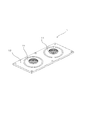
図1(a)、図1(b)に示すように、本発明による照明ランプ用レンズ板1は、たとえばアクリルあるいはポリカーボネイト等の透光素材で形成され、発光ダイオード等の発光源2に所定の間隔をもって被せられるレンズ部11を備えている(図4)。透光素材は、基本的に無色透明なものを想定しているが、各種着色剤あるいは酸化チタン等の拡散剤が配合されたものでもよい。レンズ部11は所定の厚みを有した球面の一部を切り取った基本形状である。
As shown in FIGS. 1 (a) and 1 (b), an illumination
図2に示すように複数のレンズ部11が共通の保持部13に配列されていてもよい。このときレンズ部11の個数は特に制限されず、発光源2の個数に応じて決定される。
As shown in FIG. 2, a plurality of
レンズ部11は、その外面中央部と内面周縁部とを用いて、レンズパターン12が平面視したとき重畳しないように同心円状に形成されている。ここに内面は発光源2の照射した光が入射する側の面であり、外面はその光が出射する側の面である。レンズ部11の中心軸とレンズパターン12の中心軸は通常一致させることが望ましいが、レンズ板1から斜め方向に光を照射させたい場合には、レンズ部11の中心とレンズパターン12の中心軸をずらしてもよい。
The
ここに発光源2が高出力タイプであれば、そこから発する熱もそれだけ大きなものとなる。したがって、レンズ板1が充分な耐熱性を有していないならば、発光源2とレンズ部11との間に相応の距離が必要となり、結果としてレンズ部11が大型化することになる。
If the
ところが、上記のようにレンズ部11の外面中央部と内面周縁部とを用いて、レンズパターン12を形成すれば、レンズパターン12の中央部が発光源2から遠くなる。そのため小型のレンズ部1であっても、レンズパターン12の先端が熱によって変形しにくく、レンズ部1を発光源2に近づけることができ、結果としてレンズ部が小型化される。またレンズパターン12の中央部が外面に形成されているので、突条の急峻な内斜面(フレネル段差部)に入射する分の光が少なく、効率的に光を入射および出射させられる。またレンズパターン12の周縁部はレンズ部1の内面に形成して発光源2に近づけているので、小型のレンズ板1であっても、発光源2からの光を、その部分に効率的に入射および反射させることができる。
However, if the lens pattern 12 is formed using the outer surface central portion and the inner surface peripheral edge portion of the
また同様な観点から、レンズ部11は外面側に突出したドーム形状にして、その中央部を発光源2から遠ざけるようにしてもよい。
Further, from the same viewpoint, the
このレンズ板1は、主にスポットライトあるいはダウンライト等での用途を想定したものであり、発光源2から照射される光の広がりを集光作用によって狭めることを意図している。そのためレンズパターン12の中央部は、発光源2からの光を中心軸方向に屈折させる一方、レンズパターン12の周縁部は、発光源2からの光を中心軸方向に反射させるように形成するとよい。
The
より具体的には、レンズパターン12の中央に円形凸面を配置し、その周囲に、急峻な内斜面と緩い外斜面とを有する突条を同心円状に多重配置して、円形凸面と突条の緩い外斜面とによって発光源2からの光を中心軸方向に屈折させる屈折領域12aとする。
More specifically, a circular convex surface is arranged at the center of the lens pattern 12, and ridges having steep inner slopes and loose outer slopes are concentrically arranged around the circumference, so that the circular convex surfaces and the ridges are arranged. A
そして更に外側に、いずれも急峻な内斜面と外斜面とを有する突条を同心円状に多重配置して、突条の急峻な外斜面によって発光源2からの光を中心軸方向に反射させる反射領域12bとする。このような屈折領域12aと反射領域12bからなるレンズパターン12は一種のフレネルレンズである。
Further, on the outer side, projections each having a steep inner slope and an outer slope are arranged in multiple concentric circles, and the reflection from the
発光源2が白色発光ダイオードである場合、そこから照射される光は照射方向に依存した色むらが生じやすい傾向がある。しかし上記のようにレンズパターン12を、円形凸面と、複数の突条とによって構成して、屈折あるいは全反射が生じる曲面を適宜調節することによって、それらの曲面による屈折光、反射光が重なり合う効果が生じて、照明光の色むらが抑えられる。レンズ部11の外面中央部に露出したレンズパターン12によって独特な風合いも得られる。また屈折領域12aを構成する円形凸面や突条は背が低く幅広いので、レンズ部11の外面にあっても、それらの間に埃が溜まりにくいという利点がある。
When the
基本的な構成では、レンズ部11の外面中央部に屈折領域12aを形成し、レンズ部11の内面周縁部に反射領域12bを形成する。しかしその基本構成から、屈折領域12aがレンズの内面周縁部まではみ出してその分反射領域12bが狭くなるような変形、あるいはその逆の変形も可能である。
In the basic configuration, a
ついで図3、図4に従ってレンズ部11の作用を説明する。
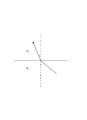
図3のように、入射角を i、屈折角を r、入射光の側の媒質の絶対屈折率をNi、
屈折光の側の媒質の絶対屈折率をNrと定義すると 、その界面においてはよく知られているように次のようなスネルの法則が成り立つ。
sin(i)/sin(r)=Nr/Ni (式1)
Next, the operation of the
As shown in FIG. 3, the incident angle is i, the refraction angle is r, the absolute refractive index of the medium on the incident light side is Ni,
If the absolute refractive index of the medium on the side of the refracted light is defined as Nr, Snell's law as follows is well known at the interface.
sin (i) / sin (r) = Nr / Ni (Formula 1)
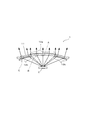
図4は、レンズ部11の縦断面における入射光と反射光の進行方向を矢印によって示している。
FIG. 4 shows the traveling directions of incident light and reflected light in the longitudinal section of the
ここで破線(A)によって囲まれた部分はレンズパターン12の中心にあって、発光源2(の中心)からの入射光は中心軸上を直進して、そのままレンズ部11を通過する。
Here, the portion surrounded by the broken line (A) is at the center of the lens pattern 12, and the incident light from the light source 2 (the center thereof) travels straight on the central axis and passes through the
破線(B)によって囲まれた部分は屈折領域12aであって、入射光はレンズ部11の内面において中心軸方向に屈折され、更にレンズ部11の外面においても中心軸方向に屈折されてレンズ部11を通過する。レンズ部11の内面および外面での屈折は上記式(1)の関係を満たす。
A portion surrounded by a broken line (B) is a
破線(C)によって囲まれた部分は反射領域12bであって、入射光はレンズ部11の内面に形成された突条の内斜面で屈折され、その突条の外斜面で全反射され、更に、レンズ部11の外面で屈折されてレンズ部11を通過する。ここで突条の内斜面およびレンズ部11の外面での屈折は上記式(1)の関係を満たすが、これらの界面に対する入射角はさほど大きくなく、反射領域12bでの作用では、突条の外斜面による全反射が重要な役割を果たす。この全反射は、上記式(1)が成立できない条件で生じる。
A portion surrounded by a broken line (C) is a
たとえばレンズ板1を形成する透光素材の絶対屈折率を1.5と仮定すれば、空気の絶対屈折率は1であるから、上記式(1)より次の式が導出される。
sin(r)=1.5×sin(i)(式2)
この式(2)は、sin(i)が1/1.5より大きいと成立しない。換言すると41度(臨界角)より大きい入射角iに対しては、式(1)を満たす出射角rが存在せず、入射光は全反射される。
For example, if the absolute refractive index of the translucent material forming the
sin (r) = 1.5 × sin (i) (Formula 2)
This equation (2) does not hold if sin (i) is greater than 1 / 1.5. In other words, for an incident angle i greater than 41 degrees (critical angle), there is no exit angle r that satisfies Equation (1), and the incident light is totally reflected.
図5は、上記のようなレンズ板1を用いた照明ランプ3の一例の外観を示している。この照明ランプ3はスポットライトであって、円筒状の遮光フード部31の奥にレンズ板1が嵌められている。その奥には、特に図示しないが、すり鉢状の反射鏡が配置され、その底部に高出力の白色発光ダイオードよりなる発光源2が配置されている。発光源2の背後には放熱装置32が取り付けられている。
FIG. 5 shows an appearance of an example of the illumination lamp 3 using the
上記レンズ板1では、レンズパターン12が形成されないレンズ部11の内面中央部と外面周縁部は平滑面とされている。しかしレンズパターン12が形成されていないレンズ部11の外面周縁部や内面中央部に拡散領域12cを設ければ、発光源2を白色発光ダイオードとしたときの色むらが更に抑えられる。
In the
図6(a)、図6(b)は、拡散領域12cをファセット加工によって形成した例である。ここではレンズ部11の外面中央部の屈折領域12aを取り巻いて、外面周縁部の全体に微小な凸面(ファセット)がタイル状に張り巡らされている。これらの凸面は凹面に置き換えても同様の効果が得られる。また拡散領域12cは、フロスト加工によっても形成でき、拡散剤を配合した被膜によっても形成できる。
6A and 6B are examples in which the
1 照明ランプ用レンズ板
11 レンズ部
12 レンズパターン
12c 拡散面
2 発光源
3 照明ランプ
DESCRIPTION OF
Claims (6)
前記レンズ部は、その外面中央部と内面周縁部とを用いて、レンズパターンが平面視したとき重畳しないように同心円状に形成されている照明ランプ用レンズ板。 In a lens plate for an illumination lamp having a lens portion that is put on a light emitting source,
A lens plate for an illumination lamp, wherein the lens portion is formed concentrically using a central portion on the outer surface and a peripheral portion on the inner surface so that the lens pattern does not overlap when viewed in plan.
前記レンズパターンの中央部は、発光源からの光を中心軸方向に屈折させ、
前記レンズパターンの周縁部は、発光源からの光を中心軸方向に反射させることを特徴とする照明ランプ用レンズ板。 In the translucent lens plate for illumination lamps of Claim 1,
The central portion of the lens pattern refracts light from the light source in the direction of the central axis,
A lens plate for an illumination lamp, wherein a peripheral portion of the lens pattern reflects light from a light source in a central axis direction.
前記レンズパターンが形成されていないレンズ部の外面周縁部には、拡散領域が形成された照明ランプ用レンズ板。 In the lens plate for illumination lamps of Claim 1 or 2,
A lens plate for an illumination lamp in which a diffusion region is formed on an outer peripheral edge portion of a lens portion on which the lens pattern is not formed.
前記拡散領域は、ファセット加工が施されている照明ランプ用レンズ板。 In the lens plate for illumination lamps of Claim 3,
The diffusion region is a lens plate for an illumination lamp that has been faceted.
スポットライトを構成する照明ランプ。
The illumination lamp according to claim 5,
Lighting lamps that make up spotlights.
Priority Applications (7)
| Application Number | Priority Date | Filing Date | Title |
|---|---|---|---|
| JP2012069871A JP5980534B2 (en) | 2012-03-26 | 2012-03-26 | Lens plate for illumination lamp and illumination lamp |
| CN201280068521.XA CN104145157A (en) | 2012-03-26 | 2012-07-19 | Lens plate for illumination lamp, and illumination lamp |
| EP12873159.3A EP2833055A4 (en) | 2012-03-26 | 2012-07-19 | Lens plate for illumination lamp, and illumination lamp |
| US14/378,939 US9534761B2 (en) | 2012-03-26 | 2012-07-19 | Lens plate for illumination lamp, and illumination lamp |
| PCT/JP2012/068308 WO2013145351A1 (en) | 2012-03-26 | 2012-07-19 | Lens plate for illumination lamp, and illumination lamp |
| PH12014501768A PH12014501768A1 (en) | 2012-03-26 | 2014-08-06 | Lens plate for illumination lamp, and illumination lamp |
| IN1667MUN2014 IN2014MN01667A (en) | 2012-03-26 | 2014-08-19 |
Applications Claiming Priority (1)
| Application Number | Priority Date | Filing Date | Title |
|---|---|---|---|
| JP2012069871A JP5980534B2 (en) | 2012-03-26 | 2012-03-26 | Lens plate for illumination lamp and illumination lamp |
Related Child Applications (1)
| Application Number | Title | Priority Date | Filing Date |
|---|---|---|---|
| JP2016147421A Division JP6326455B2 (en) | 2016-07-27 | 2016-07-27 | Lighting lamp |
Publications (2)
| Publication Number | Publication Date |
|---|---|
| JP2013201075A true JP2013201075A (en) | 2013-10-03 |
| JP5980534B2 JP5980534B2 (en) | 2016-08-31 |
Family
ID=49258701
Family Applications (1)
| Application Number | Title | Priority Date | Filing Date |
|---|---|---|---|
| JP2012069871A Active JP5980534B2 (en) | 2012-03-26 | 2012-03-26 | Lens plate for illumination lamp and illumination lamp |
Country Status (7)
| Country | Link |
|---|---|
| US (1) | US9534761B2 (en) |
| EP (1) | EP2833055A4 (en) |
| JP (1) | JP5980534B2 (en) |
| CN (1) | CN104145157A (en) |
| IN (1) | IN2014MN01667A (en) |
| PH (1) | PH12014501768A1 (en) |
| WO (1) | WO2013145351A1 (en) |
Cited By (3)
| Publication number | Priority date | Publication date | Assignee | Title |
|---|---|---|---|---|
| JP2015090776A (en) * | 2013-11-05 | 2015-05-11 | パナソニックIpマネジメント株式会社 | Lighting fixture |
| JP2016218185A (en) * | 2015-05-18 | 2016-12-22 | 株式会社遠藤照明 | Fresnel lens for lighting fixture and lighting fixture having the same |
| JP2020004477A (en) * | 2018-06-23 | 2020-01-09 | アイリスオーヤマ株式会社 | Lighting device and optical member |
Families Citing this family (6)
| Publication number | Priority date | Publication date | Assignee | Title |
|---|---|---|---|---|
| US9175832B2 (en) * | 2013-09-16 | 2015-11-03 | Light Engine Limited | Faceted LED street lamp lens |
| DE102016109647B4 (en) * | 2016-05-25 | 2022-08-25 | OSRAM Opto Semiconductors Gesellschaft mit beschränkter Haftung | Lens and lamp with such a lens |
| USD903187S1 (en) | 2019-01-25 | 2020-11-24 | Eaton Intelligent Power Limited | Optical structure |
| US11236887B2 (en) | 2019-01-25 | 2022-02-01 | Eaton Intelligent Power Limited | Optical structures for light emitting diodes (LEDs) |
| USD901752S1 (en) | 2019-01-25 | 2020-11-10 | Eaton Intelligent Power Limited | Optical structure |
| CN113791466B (en) * | 2021-11-10 | 2022-03-01 | 中国空气动力研究与发展中心低速空气动力研究所 | Wavy Fresnel lens and preparation method thereof |
Citations (7)
| Publication number | Priority date | Publication date | Assignee | Title |
|---|---|---|---|---|
| JPS598201A (en) * | 1982-07-05 | 1984-01-17 | 株式会社小糸製作所 | Lamp for vehicle |
| JP2005049367A (en) * | 2003-07-29 | 2005-02-24 | Citizen Electronics Co Ltd | Fresnel lens and lighting device |
| JP2007157542A (en) * | 2005-12-06 | 2007-06-21 | Stanley Electric Co Ltd | Illumination apparatus |
| JP2008181717A (en) * | 2007-01-23 | 2008-08-07 | Koito Mfg Co Ltd | Lighting fixture for vehicle |
| JP2010212089A (en) * | 2009-03-10 | 2010-09-24 | Koito Mfg Co Ltd | Vehicular lighting fixture |
| JP2010251013A (en) * | 2009-04-13 | 2010-11-04 | Stanley Electric Co Ltd | Lighting fixture |
| JP2011043814A (en) * | 2009-08-21 | 2011-03-03 | Mass Technology (Hk) Ltd | Fresnel lens sheet and luminaire employing the same |
Family Cites Families (11)
| Publication number | Priority date | Publication date | Assignee | Title |
|---|---|---|---|---|
| US5128848A (en) * | 1989-03-31 | 1992-07-07 | W.C. Heraeus Gmbh | Operating light |
| GB9108033D0 (en) * | 1991-04-16 | 1991-06-05 | Britax Vega Ltd | Vehicle lamp |
| US20050286145A1 (en) | 2004-06-25 | 2005-12-29 | Swarco Futurit Verkehrssignalsysteme Ges.M.B.H. | Invention concerning a condensor lens |
| JP2006054092A (en) | 2004-08-11 | 2006-02-23 | Koito Mfg Co Ltd | Vehicular marker light |
| JP2007212771A (en) | 2006-02-09 | 2007-08-23 | Taika:Kk | Fresnel lens, its manufacturing method, and its use |
| JP2008084696A (en) | 2006-09-27 | 2008-04-10 | Toshiba Corp | Lens for illumination and illumination device |
| US7733580B2 (en) * | 2006-11-06 | 2010-06-08 | Panasonic Corporation | Light emitting module and light receiving module |
| TWI322867B (en) * | 2007-04-10 | 2010-04-01 | Ind Tech Res Inst | Improved lamp fixture |
| DE102008060969A1 (en) * | 2008-12-08 | 2010-06-10 | Osram Gesellschaft mit beschränkter Haftung | diffuser |
| JP4745467B2 (en) | 2009-11-06 | 2011-08-10 | パナソニック株式会社 | Spot light source and bulb-type light source |
| JP5528287B2 (en) * | 2010-05-18 | 2014-06-25 | 株式会社エンプラス | Luminous flux control member, light emitting device, and illumination device |
-
2012
- 2012-03-26 JP JP2012069871A patent/JP5980534B2/en active Active
- 2012-07-19 EP EP12873159.3A patent/EP2833055A4/en not_active Withdrawn
- 2012-07-19 WO PCT/JP2012/068308 patent/WO2013145351A1/en active Application Filing
- 2012-07-19 CN CN201280068521.XA patent/CN104145157A/en active Pending
- 2012-07-19 US US14/378,939 patent/US9534761B2/en active Active
-
2014
- 2014-08-06 PH PH12014501768A patent/PH12014501768A1/en unknown
- 2014-08-19 IN IN1667MUN2014 patent/IN2014MN01667A/en unknown
Patent Citations (7)
| Publication number | Priority date | Publication date | Assignee | Title |
|---|---|---|---|---|
| JPS598201A (en) * | 1982-07-05 | 1984-01-17 | 株式会社小糸製作所 | Lamp for vehicle |
| JP2005049367A (en) * | 2003-07-29 | 2005-02-24 | Citizen Electronics Co Ltd | Fresnel lens and lighting device |
| JP2007157542A (en) * | 2005-12-06 | 2007-06-21 | Stanley Electric Co Ltd | Illumination apparatus |
| JP2008181717A (en) * | 2007-01-23 | 2008-08-07 | Koito Mfg Co Ltd | Lighting fixture for vehicle |
| JP2010212089A (en) * | 2009-03-10 | 2010-09-24 | Koito Mfg Co Ltd | Vehicular lighting fixture |
| JP2010251013A (en) * | 2009-04-13 | 2010-11-04 | Stanley Electric Co Ltd | Lighting fixture |
| JP2011043814A (en) * | 2009-08-21 | 2011-03-03 | Mass Technology (Hk) Ltd | Fresnel lens sheet and luminaire employing the same |
Cited By (4)
| Publication number | Priority date | Publication date | Assignee | Title |
|---|---|---|---|---|
| JP2015090776A (en) * | 2013-11-05 | 2015-05-11 | パナソニックIpマネジメント株式会社 | Lighting fixture |
| JP2016218185A (en) * | 2015-05-18 | 2016-12-22 | 株式会社遠藤照明 | Fresnel lens for lighting fixture and lighting fixture having the same |
| JP2020004477A (en) * | 2018-06-23 | 2020-01-09 | アイリスオーヤマ株式会社 | Lighting device and optical member |
| JP7064762B2 (en) | 2018-06-23 | 2022-05-11 | アイリスオーヤマ株式会社 | Lighting equipment and optics |
Also Published As
| Publication number | Publication date |
|---|---|
| EP2833055A4 (en) | 2015-10-14 |
| JP5980534B2 (en) | 2016-08-31 |
| PH12014501768B1 (en) | 2014-11-17 |
| PH12014501768A1 (en) | 2014-11-17 |
| US9534761B2 (en) | 2017-01-03 |
| IN2014MN01667A (en) | 2015-05-29 |
| US20150009683A1 (en) | 2015-01-08 |
| WO2013145351A1 (en) | 2013-10-03 |
| EP2833055A1 (en) | 2015-02-04 |
| CN104145157A (en) | 2014-11-12 |
Similar Documents
| Publication | Publication Date | Title |
|---|---|---|
| JP5980534B2 (en) | Lens plate for illumination lamp and illumination lamp | |
| JP6257132B2 (en) | Light guide device | |
| JP2004087461A (en) | Vehicle lamp | |
| JP2017524244A (en) | LED lens for backlight unit | |
| JP6507035B2 (en) | Light flux control member, light emitting device and lighting device | |
| JP2014089941A (en) | Vehicular lighting unit | |
| JP2010212021A (en) | Vehicular lighting system | |
| KR20140109137A (en) | Circular light guide and Vehicle lamp having the same | |
| JP2014103062A (en) | Lighting fixture | |
| US20180246305A1 (en) | Lighting device with virtual light source | |
| TW201447166A (en) | Light emitting diode lamp | |
| JP5668920B2 (en) | Lighting device | |
| JP5977636B2 (en) | Luminous flux control member, light emitting device, and illumination device | |
| US20110141731A1 (en) | Reflection-type light-emitting assembly | |
| JP2012209049A (en) | Led lighting device and lens | |
| TWI500884B (en) | Lighting device and cove lighting module using the same | |
| JP3197828U (en) | Lamp with uniform illuminance | |
| WO2016009798A1 (en) | Light flux control member, light-emitting device and lighting device | |
| JP2017168335A (en) | Lighting fixture for vehicle | |
| JP6326455B2 (en) | Lighting lamp | |
| JP5681513B2 (en) | Vehicle headlamp | |
| TWI386597B (en) | Optical lens and lighting device comprising the same | |
| TWM544636U (en) | Optical structure of light-guide lighting fixture | |
| KR101742196B1 (en) | Lens of light diffusion for LED device | |
| JP6386808B2 (en) | Lighting device |
Legal Events
| Date | Code | Title | Description |
|---|---|---|---|
| A621 | Written request for application examination |
Free format text: JAPANESE INTERMEDIATE CODE: A621 Effective date: 20150323 |
|
| A131 | Notification of reasons for refusal |
Free format text: JAPANESE INTERMEDIATE CODE: A131 Effective date: 20160412 |
|
| A521 | Written amendment |
Free format text: JAPANESE INTERMEDIATE CODE: A523 Effective date: 20160530 |
|
| TRDD | Decision of grant or rejection written | ||
| A01 | Written decision to grant a patent or to grant a registration (utility model) |
Free format text: JAPANESE INTERMEDIATE CODE: A01 Effective date: 20160705 |
|
| A61 | First payment of annual fees (during grant procedure) |
Free format text: JAPANESE INTERMEDIATE CODE: A61 Effective date: 20160727 |
|
| R150 | Certificate of patent or registration of utility model |
Ref document number: 5980534 Country of ref document: JP Free format text: JAPANESE INTERMEDIATE CODE: R150 |
|
| R250 | Receipt of annual fees |
Free format text: JAPANESE INTERMEDIATE CODE: R250 |
|
| R250 | Receipt of annual fees |
Free format text: JAPANESE INTERMEDIATE CODE: R250 |