JP2004087461A - Vehicle lighting - Google Patents
Vehicle lighting Download PDFInfo
- Publication number
- JP2004087461A JP2004087461A JP2003160330A JP2003160330A JP2004087461A JP 2004087461 A JP2004087461 A JP 2004087461A JP 2003160330 A JP2003160330 A JP 2003160330A JP 2003160330 A JP2003160330 A JP 2003160330A JP 2004087461 A JP2004087461 A JP 2004087461A
- Authority
- JP
- Japan
- Prior art keywords
- light
- reflector
- optical axis
- transmitting member
- lamp
- Prior art date
- Legal status (The legal status is an assumption and is not a legal conclusion. Google has not performed a legal analysis and makes no representation as to the accuracy of the status listed.)
- Granted
Links
Images








Classifications
-
- F—MECHANICAL ENGINEERING; LIGHTING; HEATING; WEAPONS; BLASTING
- F21—LIGHTING
- F21S—NON-PORTABLE LIGHTING DEVICES; SYSTEMS THEREOF; VEHICLE LIGHTING DEVICES SPECIALLY ADAPTED FOR VEHICLE EXTERIORS
- F21S43/00—Signalling devices specially adapted for vehicle exteriors, e.g. brake lamps, direction indicator lights or reversing lights
- F21S43/30—Signalling devices specially adapted for vehicle exteriors, e.g. brake lamps, direction indicator lights or reversing lights characterised by reflectors
-
- F—MECHANICAL ENGINEERING; LIGHTING; HEATING; WEAPONS; BLASTING
- F21—LIGHTING
- F21V—FUNCTIONAL FEATURES OR DETAILS OF LIGHTING DEVICES OR SYSTEMS THEREOF; STRUCTURAL COMBINATIONS OF LIGHTING DEVICES WITH OTHER ARTICLES, NOT OTHERWISE PROVIDED FOR
- F21V7/00—Reflectors for light sources
- F21V7/0091—Reflectors for light sources using total internal reflection
-
- F—MECHANICAL ENGINEERING; LIGHTING; HEATING; WEAPONS; BLASTING
- F21—LIGHTING
- F21S—NON-PORTABLE LIGHTING DEVICES; SYSTEMS THEREOF; VEHICLE LIGHTING DEVICES SPECIALLY ADAPTED FOR VEHICLE EXTERIORS
- F21S43/00—Signalling devices specially adapted for vehicle exteriors, e.g. brake lamps, direction indicator lights or reversing lights
- F21S43/10—Signalling devices specially adapted for vehicle exteriors, e.g. brake lamps, direction indicator lights or reversing lights characterised by the light source
- F21S43/13—Signalling devices specially adapted for vehicle exteriors, e.g. brake lamps, direction indicator lights or reversing lights characterised by the light source characterised by the type of light source
- F21S43/14—Light emitting diodes [LED]
-
- F—MECHANICAL ENGINEERING; LIGHTING; HEATING; WEAPONS; BLASTING
- F21—LIGHTING
- F21S—NON-PORTABLE LIGHTING DEVICES; SYSTEMS THEREOF; VEHICLE LIGHTING DEVICES SPECIALLY ADAPTED FOR VEHICLE EXTERIORS
- F21S43/00—Signalling devices specially adapted for vehicle exteriors, e.g. brake lamps, direction indicator lights or reversing lights
- F21S43/20—Signalling devices specially adapted for vehicle exteriors, e.g. brake lamps, direction indicator lights or reversing lights characterised by refractors, transparent cover plates, light guides or filters
- F21S43/235—Light guides
- F21S43/236—Light guides characterised by the shape of the light guide
- F21S43/239—Light guides characterised by the shape of the light guide plate-shaped
-
- F—MECHANICAL ENGINEERING; LIGHTING; HEATING; WEAPONS; BLASTING
- F21—LIGHTING
- F21S—NON-PORTABLE LIGHTING DEVICES; SYSTEMS THEREOF; VEHICLE LIGHTING DEVICES SPECIALLY ADAPTED FOR VEHICLE EXTERIORS
- F21S43/00—Signalling devices specially adapted for vehicle exteriors, e.g. brake lamps, direction indicator lights or reversing lights
- F21S43/20—Signalling devices specially adapted for vehicle exteriors, e.g. brake lamps, direction indicator lights or reversing lights characterised by refractors, transparent cover plates, light guides or filters
- F21S43/235—Light guides
- F21S43/236—Light guides characterised by the shape of the light guide
- F21S43/241—Light guides characterised by the shape of the light guide of complex shape
-
- F—MECHANICAL ENGINEERING; LIGHTING; HEATING; WEAPONS; BLASTING
- F21—LIGHTING
- F21S—NON-PORTABLE LIGHTING DEVICES; SYSTEMS THEREOF; VEHICLE LIGHTING DEVICES SPECIALLY ADAPTED FOR VEHICLE EXTERIORS
- F21S43/00—Signalling devices specially adapted for vehicle exteriors, e.g. brake lamps, direction indicator lights or reversing lights
- F21S43/20—Signalling devices specially adapted for vehicle exteriors, e.g. brake lamps, direction indicator lights or reversing lights characterised by refractors, transparent cover plates, light guides or filters
- F21S43/235—Light guides
- F21S43/242—Light guides characterised by the emission area
- F21S43/243—Light guides characterised by the emission area emitting light from one or more of its extremities
-
- F—MECHANICAL ENGINEERING; LIGHTING; HEATING; WEAPONS; BLASTING
- F21—LIGHTING
- F21S—NON-PORTABLE LIGHTING DEVICES; SYSTEMS THEREOF; VEHICLE LIGHTING DEVICES SPECIALLY ADAPTED FOR VEHICLE EXTERIORS
- F21S43/00—Signalling devices specially adapted for vehicle exteriors, e.g. brake lamps, direction indicator lights or reversing lights
- F21S43/20—Signalling devices specially adapted for vehicle exteriors, e.g. brake lamps, direction indicator lights or reversing lights characterised by refractors, transparent cover plates, light guides or filters
- F21S43/235—Light guides
- F21S43/242—Light guides characterised by the emission area
- F21S43/245—Light guides characterised by the emission area emitting light from one or more of its major surfaces
-
- F—MECHANICAL ENGINEERING; LIGHTING; HEATING; WEAPONS; BLASTING
- F21—LIGHTING
- F21S—NON-PORTABLE LIGHTING DEVICES; SYSTEMS THEREOF; VEHICLE LIGHTING DEVICES SPECIALLY ADAPTED FOR VEHICLE EXTERIORS
- F21S43/00—Signalling devices specially adapted for vehicle exteriors, e.g. brake lamps, direction indicator lights or reversing lights
- F21S43/20—Signalling devices specially adapted for vehicle exteriors, e.g. brake lamps, direction indicator lights or reversing lights characterised by refractors, transparent cover plates, light guides or filters
- F21S43/235—Light guides
- F21S43/247—Light guides with a single light source being coupled into the light guide
-
- F—MECHANICAL ENGINEERING; LIGHTING; HEATING; WEAPONS; BLASTING
- F21—LIGHTING
- F21S—NON-PORTABLE LIGHTING DEVICES; SYSTEMS THEREOF; VEHICLE LIGHTING DEVICES SPECIALLY ADAPTED FOR VEHICLE EXTERIORS
- F21S43/00—Signalling devices specially adapted for vehicle exteriors, e.g. brake lamps, direction indicator lights or reversing lights
- F21S43/30—Signalling devices specially adapted for vehicle exteriors, e.g. brake lamps, direction indicator lights or reversing lights characterised by reflectors
- F21S43/31—Optical layout thereof
- F21S43/315—Optical layout thereof using total internal reflection
-
- F—MECHANICAL ENGINEERING; LIGHTING; HEATING; WEAPONS; BLASTING
- F21—LIGHTING
- F21S—NON-PORTABLE LIGHTING DEVICES; SYSTEMS THEREOF; VEHICLE LIGHTING DEVICES SPECIALLY ADAPTED FOR VEHICLE EXTERIORS
- F21S43/00—Signalling devices specially adapted for vehicle exteriors, e.g. brake lamps, direction indicator lights or reversing lights
- F21S43/40—Signalling devices specially adapted for vehicle exteriors, e.g. brake lamps, direction indicator lights or reversing lights characterised by the combination of reflectors and refractors
-
- F—MECHANICAL ENGINEERING; LIGHTING; HEATING; WEAPONS; BLASTING
- F21—LIGHTING
- F21W—INDEXING SCHEME ASSOCIATED WITH SUBCLASSES F21K, F21L, F21S and F21V, RELATING TO USES OR APPLICATIONS OF LIGHTING DEVICES OR SYSTEMS
- F21W2103/00—Exterior vehicle lighting devices for signalling purposes
-
- F—MECHANICAL ENGINEERING; LIGHTING; HEATING; WEAPONS; BLASTING
- F21—LIGHTING
- F21W—INDEXING SCHEME ASSOCIATED WITH SUBCLASSES F21K, F21L, F21S and F21V, RELATING TO USES OR APPLICATIONS OF LIGHTING DEVICES OR SYSTEMS
- F21W2107/00—Use or application of lighting devices on or in particular types of vehicles
- F21W2107/10—Use or application of lighting devices on or in particular types of vehicles for land vehicles
-
- F—MECHANICAL ENGINEERING; LIGHTING; HEATING; WEAPONS; BLASTING
- F21—LIGHTING
- F21Y—INDEXING SCHEME ASSOCIATED WITH SUBCLASSES F21K, F21L, F21S and F21V, RELATING TO THE FORM OR THE KIND OF THE LIGHT SOURCES OR OF THE COLOUR OF THE LIGHT EMITTED
- F21Y2105/00—Planar light sources
- F21Y2105/10—Planar light sources comprising a two-dimensional [2D] array of point-like light-generating elements
-
- F—MECHANICAL ENGINEERING; LIGHTING; HEATING; WEAPONS; BLASTING
- F21—LIGHTING
- F21Y—INDEXING SCHEME ASSOCIATED WITH SUBCLASSES F21K, F21L, F21S and F21V, RELATING TO THE FORM OR THE KIND OF THE LIGHT SOURCES OR OF THE COLOUR OF THE LIGHT EMITTED
- F21Y2115/00—Light-generating elements of semiconductor light sources
- F21Y2115/10—Light-emitting diodes [LED]
Landscapes
- Engineering & Computer Science (AREA)
- General Engineering & Computer Science (AREA)
- Physics & Mathematics (AREA)
- Microelectronics & Electronic Packaging (AREA)
- Optics & Photonics (AREA)
- Non-Portable Lighting Devices Or Systems Thereof (AREA)
- Led Device Packages (AREA)
Abstract
【課題】LED光源を備えた車両用灯具において、リフレクタの薄型化を図った上で、その反射面全域が光って見えるようにする。
【解決手段】灯具前方へ向けて配置されたLED光源12からの光を透光部材14に入射させ、これを透過した光をリフレクタ16により灯具前方へ反射させる構成とする。その際、透光部材14の表面に、LED光源12の光軸Axに対して小角度で入射した光を光軸Axと略直交する方向へ内面反射させる内面反射部14Bと、光軸Axに対して大角度で入射した光を光軸Axと略直交する方向へ屈折させる屈折部14Cとを形成する。これにより、LED出射光を光軸Axと略直交する方向へ向かう略平行光としてリフレクタ16の反射面16aに入射させる。そして、リフレクタ16の奥行き寸法を大きくすることなく反射面16aの周縁部にまでLED出射光を入射させるとともに、リフレクタ16による反射制御を容易化する。
【選択図】 図3An object of the present invention is to reduce the thickness of a reflector in a vehicular lamp provided with an LED light source, and to make the entire reflection surface shine.
A light from an LED light source (12) disposed forward of a lamp is made incident on a light transmitting member (14), and light transmitted through the light is reflected by a reflector (16) to the front of the lamp. At this time, an inner reflecting portion 14B for internally reflecting light incident on the surface of the light transmitting member 14 at a small angle with respect to the optical axis Ax of the LED light source 12 in a direction substantially orthogonal to the optical axis Ax; A refraction portion 14C for refracting light incident at a large angle in a direction substantially orthogonal to the optical axis Ax is formed. Thus, the LED emission light is made to enter the reflection surface 16a of the reflector 16 as substantially parallel light traveling in a direction substantially orthogonal to the optical axis Ax. Then, the LED emission light is allowed to enter the peripheral portion of the reflection surface 16a without increasing the depth dimension of the reflector 16, and the reflection control by the reflector 16 is facilitated.
[Selection diagram] FIG.
Description
【0001】
【発明の属する技術分野】
本願発明は、LED(発光ダイオード)光源を備えた車両用灯具に関するものである。
【0002】
【従来の技術】
近年、LED光源を備えた車両用灯具が多く採用されている。その際、「特許文献1」には、灯具前方へ向けて配置されたLED光源からの光を透光部材に入射させ、この透光部材を透過したLED光源からの光を、該透光部材と一体的に形成されたリフレクタにより灯具前方へ反射させるように構成された車両用灯具が記載されている。
【0003】
このような灯具構成を採用することにより、LED光源からの光をリフレクタ反射光として効率良く利用することが可能となる。
【0004】
【特許文献1】
実開昭61−153201号公報
【発明が解決しようとする課題】
しかしながら、上記「特許文献1」記載の車両用灯具においては、リフレクタの反射面への入射光の向きが反射面の各部位において異なったものとなる。このため、リフレクタを灯具前方から観察したとき、その反射面が全域にわたって光って見えるように反射面を形成することが容易でなく、また、これを実現するためにはリフレクタの奥行き寸法をある程度大きくする必要がある、という問題がある。
【0005】
本願発明は、このような事情に鑑みてなされたものであって、LED光源を備えた車両用灯具において、リフレクタの薄型化を図った上で、その反射面全域が光って見えるようにすることができる車両用灯具を提供することを目的とするものである。
【0006】
【課題を解決するための手段】
本願発明は、透光部材の形状に工夫を施すことにより、上記目的達成を図るようにしたものである。
すなわち、本願発明に係る車両用灯具は、
灯具前方へ向けて配置されたLED光源と、このLED光源からの光を入射させるように配置された透光部材と、この透光部材を透過した上記LED光源からの光を灯具前方へ反射させるように配置されたリフレクタと、を備えてなる車両用灯具において、
上記透光部材の表面に、上記LED光源の光軸に対して小角度で該透光部材に入射した小角度入射光を上記光軸と略直交する方向へ内面反射させる内面反射部と、上記光軸に対して大角度で該透光部材に入射した大角度入射光を上記光軸と略直交する方向へ屈折させる屈折部とが形成されている、ことを特徴とするものである。
【0007】
上記「車両用灯具」は、特定種類の車両用灯具に限定されるものではなく、例えば、テールランプ、ストップランプ等が採用可能である。
【0008】
上記「透光部材」は、透光性を有する部材であれば、その材質は特に限定されるものではなく、例えば、透明な合成樹脂で構成されたものやガラスで構成されたもの等が採用可能である。また、この透光部材の「内面反射部」および「屈折部」の具体的形状についても特に限定されるものではない。
【0009】
上記「リフレクタ」は、透光部材を透過したLED光源からの光を灯具前方へ反射させるように配置されたものであれば、その具体的な反射面形状等は特に限定されるものではない。また、この「リフレクタ」は、その外表面においてLED光源からの光を反射させるように構成された通常のリフレクタであってもよいし、あるいは、透明な部材で構成されたリフレクタであって該リフレクタを透過したLED光源からの光を内面反射させるように構成されたものであってもよい。後者の場合、リフレクタは、透光部材と別体で構成してもよいし、該リフレクタの一部を透光部材と一体で構成してもよい。
【0010】
【発明の作用効果】
上記構成に示すように、本願発明に係る車両用灯具は、灯具前方へ向けて配置されたLED光源からの光を透光部材に入射させ、この透光部材を透過したLED光源からの光を、リフレクタにより灯具前方へ反射させるように構成されているが、透光部材の表面には、LED光源の光軸に対して小角度で該透光部材に入射した小角度入射光を上記光軸と略直交する方向へ内面反射させる内面反射部と、上記光軸に対して大角度で該透光部材に入射した大角度入射光を上記光軸と略直交する方向へ屈折させる屈折部とが形成されているので、LED光源からの光を上記光軸と略直交する方向へ向かう略平行光としてリフレクタの反射面に入射させることができる。
【0011】
このため、リフレクタの奥行き寸法を大きくすることなく、その反射面の周縁部にまでLED光源からの光を入射させることができる。また、LED光源からの光が略平行光としてリフレクタの反射面に入射するので、リフレクタによる反射制御を容易に行うことが可能となる。
【0012】
したがって本願発明によれば、LED光源を備えた車両用灯具において、リフレクタの薄型化を図った上で、その反射面全域が光って見えるようにすることができる。そしてこれにより灯具の見映えを向上させることができる。
【0013】
上記構成において、透光部材の内面反射部を、上記光軸を中心とする略ロート状の回転曲面で構成するとともに、透光部材の屈折部を、上記光軸を中心とする略円環ドーム状の回転曲面で構成するようにすれば、次のような作用効果を得ることができる。
【0014】
すなわち、LED光源からの光を、上記光軸の全周にわたって該光軸と略直交する方向へ向かう略平行光としてリフレクタの反射面に入射させることができるので、1つのLED光源で広い発光面積を確保することができる。しかも、LED光源を灯具中央に配置することができるので、灯具の外形形状を自由に設定することができる。
【0015】
また上記構成において、リフレクタの反射面を、透光部材を透過したLED光源からの光を灯具前方へ反射させる複数の反射素子からなる構成とし、そして、これら反射素子を上記光軸と略直交する方向に延びる段差部を介して階段状に配置すれば、灯具を一層薄型化することができ、しかも、リフレクタの反射面をその全域にわたって略均一に散点的に光って見えるようにすることができる。この場合において、各「反射素子」は、LED光源からの光を単に灯具前方へ偏向させるように反射させる面形状で構成してもよいし、LED光源からの光を灯具前方へ偏向させると共に拡散させるように反射させる面形状で構成してもよい。
【0016】
さらに上記構成において、リフレクタの反射面の少なくとも一部を、透光部材を透過したLED光源からの光を内面反射により灯具前方へ反射させる構成とすれば、リフレクタの肉厚分だけ灯具をよりコンパクトに構成することができる。
【0017】
また上記構成において、透光部材の表面に、上記小角度入射光のうち光軸の近傍領域に入射した光を前方へ透過させる直射部が形成された構成とすれば、リフレクタの反射面のみならず、透光部材の直射部も光って見えるようにすることができ、これにより灯具の見映えを一層向上させることができる。
【0018】
ところで本願発明に係る車両用灯具は、LED光源、透光部材およびリフレクタを1組だけ備えた構成としてもよいが、これらLED光源、透光部材およびリフレクタを複数組備えた構成としてもよい。後者の構成を採用した場合には、車両用灯具の明るさを一層増大させることができる。その際、本願発明においては、リフレクタの外形形状を自由に設定することが可能であるので、これら複数組のLED光源、透光部材およびリフレクタを灯具形状等に応じて自由に配列することも可能となる。
【0019】
【発明の実施の形態】
以下、図面を用いて、本願発明の一実施形態について説明する。
【0020】
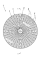
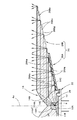
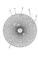
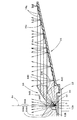
図1は、本実施形態に係る車両用灯具を示す正面図であり、図2は、図1のII−II 線断面図であり、図3は、図2の要部詳細図である。
【0021】
これらの図に示すように、本実施形態に係る車両用灯具10は、車両後端部に設けられるテールランプであって、LED光源12と、透光部材14と、リフレクタ16と、透光カバー18とを備えてなっている。
【0022】
LED光源12は、その光軸Axを車両前後方向に延びる灯具中心軸に一致させるようにして灯具前方(車両としては「後方」、以下同様)へ向けて配置されている。このLED光源12は、LED本体(LEDチップ)12Aと、このLED本体12Aの発光中心Oを略半球状に覆う封止樹脂12Bとからなり、基板20を介して基板支持部材22に固定されている。
【0023】
透光部材14は、LED光源12を前方側から覆うように配置された透明な合成樹脂成形品からなり、その後面部において基板支持部材22に固定されている。
【0024】
この透光部材14の後面部には、LED光源12からの光(以下「LED出射光」ともいう)を入射させる光入射用凹部14Aが形成されている。この光入射用凹部14Aは、発光中心Oを球面状に囲む球状部14A1と、光軸Axを円筒面状に囲む円筒部14A2とからなっている。そして、LED出射光のうち、光軸Axに対して小角度(具体的には例えば40°程度以下の角度)で出射される光は、球状部14A1に対して垂直に入射した後、透光部材14内をそのまま直進し、一方、光軸Axに対して大角度(具体的には例えば40°程度を超える角度)で出射される光は、円筒部14A2に対して斜めに入射した後、透光部材14内を該透光部材14の外周側へ屈折して進む。
【0025】
この透光部材14の表面には、光軸Axに対して小角度で該透光部材14に入射した小角度入射光(球状部14A1への入射光)を、光軸Axと略直交する方向へ内面反射させる内面反射部14Bと、光軸Axに対して大角度で該透光部材14に入射した大角度入射光(円筒部14A2への入射光)を、光軸Axと略直交する方向へ屈折させる屈折部14Cとが形成されている。
【0026】
内面反射部14Bは、透光部材14の前面部において、光軸Axを中心とする略ロート状の回転曲面で構成されている。一方、屈折部14Cは、内面反射部14Bの後方側において、光軸Axを中心とする略円環ドーム状の回転曲面で構成されている。
【0027】
透光部材14の表面における内面反射部14Bの外周側に位置する部分は、光軸Axを中心とする円筒面からなる円筒状外周部14Dとして形成されている。そしてこれにより、内面反射部14Bで内面反射して光軸Axと略直交する方向へ向かうLED出射光を、該円筒状外周部14Dから透光部材14外へそのまま直進させるようになっている。この円筒状外周部14Dの後端部は、光軸Axと直交する平面からなる環状平面部14Eとして形成されている。そしてこれにより、内面反射部14Bで内面反射したLED出射光および屈折部14Cで屈折したLED出射光が、環状平面部14Eによって遮られてしまうことがないようにしている。
【0028】
リフレクタ16は、透光部材14を透過したLED出射光を灯具前方へ反射させるように配置されている。このリフレクタ16は、偏平な円錐面形状に形成された合成樹脂成形品の前面に反射面処理が施されてなり、灯具正面視において円形の外形形状を有している。
【0029】
このリフレクタ16の反射面16aは、透光部材14を透過したLED出射光を灯具前方へ反射させる複数の反射素子16sからなっている。これら反射素子16sは、反射面16aを放射状に区分けするとともに同心状に区分けするようにして配置されている。その際、これら反射素子16sは、径方向に関しては光軸Axと略直交する平面に沿って延びる段差部16gを介して等間隔で階段状に配置されている。
【0030】
これら各反射素子16sは、光軸Axを中心軸とする頂角90°の円錐面を基準面として、光軸Axに関して径方向および円周方向に所定の曲率を有する凸曲面状に形成されており、これにより透光部材14からのLED出射光を光軸Axに関して径方向および円周方向に拡散反射させるようになっている。
【0031】
透光カバー18は、透明な合成樹脂成形品で構成された素通し状のカバーであって、灯具正面視において円形の外形形状を有している。そして、この透光カバー18は、その外周縁部においてリフレクタ16に固定されている。
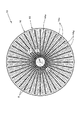
図4は、本実施形態に係る車両用灯具10を、そのLED光源12を点灯させた状態で示す正面図である。
【0032】
図示のように、車両用灯具10を正面方向から観察したとき、そのリフレクタ16の反射面16aを構成する複数の反射素子16sが同時に散点的に光って見える。その際、各反射素子16sは、上述したように光軸Axを中心軸とする頂角90°の円錐面を基準面として凸曲面状に形成されており、かつ、これら各反射素子16sにはLED出射光が略平行光として入射するので、その中央部分が光輝部Bとして明るく光って見える。
【0033】
灯具正面方向から視点を多少ずらした場合においても、各反射素子16sにはLED出射光が略平行光として入射しているので、各反射素子16sは視点移動量に応じてその中央部分からずれた部分が光輝部Bとして明るく光って見える。
【0034】
以上詳述したように、本実施形態に係る車両用灯具10は、灯具前方へ向けて配置されたLED光源12からの光を透光部材14に入射させ、この透光部材14を透過したLED出射光を、リフレクタ16により灯具前方へ反射させるように構成されているが、透光部材14の表面には、LED光源12の光軸Axに対して小角度で該透光部材14に入射した小角度入射光を、光軸Axと略直交する方向へ内面反射させる内面反射部14Bと、光軸Axに対して大角度で該透光部材14に入射した大角度入射光を、光軸Axと略直交する方向へ屈折させる屈折部14Cとが形成されているので、LED出射光を光軸Axと略直交する方向へ向かう略平行光としてリフレクタ16の反射面16aに入射させることができる。
【0035】
このため、リフレクタ16の奥行き寸法を大きくすることなく、その反射面16aの周縁部にまでLED出射光を入射させることができる。また、LED出射光が略平行光としてリフレクタ16の反射面16aに入射するので、リフレクタ16による反射制御を容易に行うことが可能となる。
【0036】
したがって本実施形態によれば、リフレクタ16の薄型化を図った上で、その反射面16aの全域が光って見えるようにすることができる。そしてこれにより灯具の見映えを向上させることができる。
【0037】
特に本実施形態においては、透光部材14の内面反射部14Bが、光軸Axを中心とする略ロート状の回転曲面で構成されるとともに、透光部材14の屈折部14Cが、光軸Axを中心とする略円環ドーム状の回転曲面で構成されているので、次のような作用効果を得ることができる。
【0038】
すなわち、LED出射光を光軸Axの全周にわたって該光軸Axと略直交する方向へ向かう略平行光としてリフレクタ16の反射面16aに入射させることができるので、1つのLED光源12で広い発光面積を確保することができる。しかも、LED光源12を灯具中央に配置することができるので、灯具の外形形状を自由に設定することができる。
【0039】
また本実施形態においては、リフレクタ16の反射面16aが、透光部材14を透過したLED出射光を灯具前方へ反射させる複数の反射素子16sからなり、そして、これら反射素子16sが、光軸Axと略直交する方向に延びる段差部16gを介して階段状に配置されているので、灯具を一層薄型化することができ、しかも、リフレクタ16の反射面16aをその全域にわたって略均一に散点的に光って見えるようにすることができる。
【0040】
なお本実施形態においては、各反射素子16sが、透光部材14からのLED出射光を光軸Axに関して径方向および円周方向に拡散反射させる面形状で構成されているが、このようにする代わりに、各反射素子16sを透光部材14からのLED出射光を単に灯具前方へ偏向させるように反射させる面形状で構成し、透光カバー18等に拡散機能を持たせるようにすることも可能である。
次に、上記実施形態の第1変形例について説明する。
図5は、本変形例に係るリフレクタ26を示す、図3と同様の図である。
【0041】
図示のように、このリフレクタ26は、透光部材14の屈折部14CからのLED出射光が入射する内周寄りの部分は通常リフレクタ部26Aとして構成されているが、透光部材14の内面反射部14BからのLED出射光が入射する外周寄りの部分は内面反射リフレクタ部26Bとして構成されている。
【0042】
通常リフレクタ部26Aは、上記実施形態のリフレクタ16における内周寄りの部分と同様の構成となっている。すなわち、このリフレクタ26の反射面26Aaは、複数の反射素子26Asからなり、段差部26Agを介して等間隔で階段状に配置されている。
【0043】
一方、内面反射リフレクタ部26Bは、透光部材14を透過したLED出射光を内面反射により灯具前方へ反射させるように構成されている。すなわち、この内面反射リフレクタ部26Bは、透光部材14をその円筒状外周部14D(図3参照)から外周方向へ延長させるようにして該透光部材14と一体で構成されており、その外周端面に反射面26Baが形成されている。この反射面26Baは、複数の反射素子26Bsからなり、段差部26Bgを介して等間隔で階段状に配置されている。
【0044】
本変形例の構成を採用した場合においても、上記実施形態の場合と同様、リフレクタ26の薄型化を図った上で、その反射面26Aa、26Baの全域が光って見えるようにすることができる。
【0045】
しかも本変形例の構成を採用した場合には、内面反射リフレクタ部26Bが、上記実施形態のリフレクタ16において透光部材14の内面反射部14BからのLED出射光が入射する外周寄りの部分に比して、該リフレクタ16の肉厚分だけ小さくなるので、灯具をコンパクトに構成することができる。
【0046】
さらに本変形例においては、内面反射リフレクタ部26Bが透明な部材で構成されているので、特にLED光源12の非点灯時における見映えに関して透明感(クリスタル感)を演出することができる。
次に、上記実施形態の第2変形例について説明する。
図6は、本変形例に係るリフレクタ36を示す、図3と同様の図である。
【0047】
図示のように、このリフレクタ36は、透光部材14の内面反射部14BからのLED出射光が入射する外周寄りの部分については、第1変形例に係るリフレクタ26の内面反射リフレクタ部26Bと同様の内面反射リフレクタ部36Bとして構成されている。すなわち、この内面反射リフレクタ部36Bの反射面36Baは、複数の反射素子36Bsからなり、段差部36Bgを介して等間隔で階段状に配置されている。
【0048】
一方、本変形例のリフレクタ36において、透光部材14の屈折部14CからのLED出射光が入射する内周寄りの部分は、内面反射リフレクタ部36Aとして構成されている。この内面反射リフレクタ部36Aは、透光部材14とは別体の透明な合成樹脂成形品で構成されており、その反射面36Aaは、複数の反射素子36Asからなり、段差部36Agを介して等間隔で階段状に配置されている。
【0049】
本変形例の構成を採用した場合においても、上記実施形態の場合と同様、リフレクタ36の薄型化を図った上で、その反射面36Aa、36Baの全域が光って見えるようにすることができる。
【0050】
しかも本変形例の構成を採用した場合には、リフレクタ36が、上記実施形態のリフレクタ16に比して該リフレクタ16の肉厚分だけ小さくなるので、灯具を一層コンパクトに構成することができる。
【0051】
さらに本変形例においては、リフレクタ36全体が透明な部材で構成されているので、特にLED光源12の非点灯時における見映えに関して一層の透明感(クリスタル感)を演出することができる。
次に、上記実施形態の第3変形例について説明する。
図7は、本変形例に係る透光部材24を示す、図3と同様の図である。
【0052】
図示のように、この透光部材24は、その光入射用凹部24Aの構成が上記実施形態の透光部材14の光入射用凹部14Aと異なっている。
【0053】
すなわち、この透光部材24の光入射用凹部24Aは、LED光源12の封止樹脂12Bに近接した位置で発光中心Oを球面状に囲む第1球状部24A1と、この第1球状部24A1の周囲において、該第1球状部24A1よりも大きい半径で発光中心Oを球面状に囲む第2球状部24A2とからなっている。そして、LED出射光のうち、光軸Axに対して小角度で出射される光は、第1球状部24A1に対して垂直に入射した後、透光部材24内をそのまま直進し、一方、光軸Axに対して大角度で出射される光も、第2球状部24A2に対して垂直に入射した後、透光部材24内をそのまま直進する。
【0054】
この透光部材24の表面には、上記実施形態と同様、内面反射部24Bと、屈折部24Cと、円筒状外周部24Dと、環状平面部24Eとが形成されている。これらのうち、内面反射部24B、円筒状外周部24Dおよび環状平面部24Eについては、上記実施形態の構成と全く同様であるが、屈折部24Cは、発光中心Oから放射状に透光部材24内を直進するLED出射光を光軸Axと略直交する方向へ屈折させる必要上、その前端部が上記実施形態の屈折部14Cに比してやや光軸Ax寄りに食い込むように形成されている。
【0055】
本変形例の構成を採用した場合においても、上記実施形態の場合と同様、LED出射光を光軸Axと略直交する方向へ向かう略平行光としてリフレクタ16の反射面16aに入射させることができる。
【0056】
しかも本変形例の構成を採用した場合には、LED出射光が透光部材24内を放射状に直進するので、屈折部24Cの曲面形状を設定する際の光学計算を容易に行うことが可能となる。
次に、上記実施形態の第4変形例について説明する。
図8は、本変形例に係る透光部材34を示す、図3と同様の図である。
【0057】
図示のように、この透光部材34は、その光入射用凹部34Aの構成が上記実施形態の透光部材14の光入射用凹部14Aと異なっている。
【0058】
すなわち、この透光部材34の光入射用凹部34Aは、有底円筒状に形成されている。そして、この光入射用凹部34AとLED光源12の封止樹脂12Bとの間には、透明な充填剤40が充填されている。この充填剤40は、透光部材34と屈折率が略等しい合成樹脂材料からなっている。この透光部材34においては、LED出射光が充填剤40を介して該透光部材34内をLED光源12の発光中心Oから放射状に直進することとなる。
【0059】
この透光部材34の内面反射部34B、屈折部34C、円筒状外周部34Dおよび環状平面部34Eは、第3変形例の透光部材24と全く同じ形状に設定されている。
本変形例の構成を採用した場合においても、上記第3変形例と同様の作用効果を得ることができる。
【0060】
しかも本変形例においては、光入射用凹部34AとLED光源12の封止樹脂12Bとの間に透光部材34と屈折率が略等しい充填剤40が充填されているので、充填剤40と透光部材34との間の界面でほとんど屈折することがなく、したがって透光部材34の光入射用凹部34Aの形状を任意に設定することが可能となる。なお本変形例においては、光入射用凹部34Aが有底円筒状という単純な形状に設定されているが、これ以外の形状に設定することももちろん可能である。
次に、上記実施形態の第5変形例について説明する。
図9は、本変形例に係る透光部材44を示す、図3と同様の図である。
【0061】
図示のように、この透光部材44は、その光入射用凹部44Aの構成が上記実施形態の透光部材14の光入射用凹部14Aと異なっている。
【0062】
すなわち、この透光部材44は、その光入射用凹部44AがLED光源12の封止樹脂12Bと密着するように形成されている。この透光部材44においては、LED出射光が該透光部材44内をLED光源12の発光中心Oから放射状に直進することとなる。
【0063】
この透光部材44の内面反射部44B、屈折部44C、円筒状外周部44Dおよび環状平面部44Eは、第3変形例の透光部材24と全く同じ形状に設定されている。
本変形例の構成を採用した場合においても、上記第3変形例と同様の作用効果を得ることができる。
【0064】
しかも本変形例においては、透光部材44の光入射用凹部44AがLED光源12の封止樹脂12Bと密着するように形成されているので、透光部材44をインサート成形等により容易に形成することができ、しかも透光部材44の位置精度を高めることができる。
次に、上記実施形態の第6変形例について説明する。
図10は、本変形例に係る透光部材54を示す、図3と同様の図である。
【0065】
図示のように、この透光部材54は、LED光源12のLED本体12Aを封止するように形成されており、これによりLED光源12の封止樹脂12B(図3参照)としての機能も果たすようになっている。そして、この透光部材54には、上記実施形態の透光部材14のような光入射用凹部14A(図3参照)は形成されていない。この透光部材54においては、LED出射光が該透光部材54内をLED光源12の発光中心Oから放射状に直進することとなる。
【0066】
この透光部材54の内面反射部54B、屈折部54C、円筒状外周部54Dおよび環状平面部54Eは、第3変形例の透光部材24と全く同じ形状に設定されている。
本変形例の構成を採用した場合においても、上記第3変形例と同様の作用効果を得ることができる。
【0067】
しかも本変形例においては、透光部材54がLED光源12のLED本体12Aを封止するように形成されているので、部品点数を削減することができるとともに、透光部材54の位置精度を高めることができる。
次に、上記実施形態の第7および第8変形例について説明する。
【0068】
図11および12は、これら各変形例に係るリフレクタ46、56を示す、図4と同様の図である。
【0069】
これらの図に示すように、第7および第8変形例に係るリフレクタ46、56は、その反射面46a、56aに形成された複数の反射素子46s、56sの配列が上記実施形態のリフレクタ16と異なっている。
【0070】
すなわち、これら各リフレクタ46、56は、上記実施形態のリフレクタ16と同様、反射面46a、56aが放射状および同心状に区分けされており、その各々に反射素子46s、56sおよび段差部46g、56gが割り付けられているが、その際、第4変形例においては各反射素子46sの位置が径方向1ピッチおきに周方向に半ピッチずれており、一方、第5変形例においては各反射素子56sの位置が周方向1ピッチおきに径方向に半ピッチずれている。
【0071】
なお、これら各反射素子46s、56sが、光軸Axに関して径方向および円周方向に所定の曲率を有する凸曲面状に形成されている点については、上記実施形態と同様である。
【0072】
LED光源12を点灯させた状態でリフレクタ54、64を正面方向から観察したとき、その反射面46a、56aを構成する各反射素子46s、56sの略中央部分が光輝部Bとして明るく光って見えるが、これら各反射素子46s、56sの配列は上記実施形態と異なっているので、これら各変形例においては上記実施形態とは趣の異なる見え方をそれぞれ実現することができる。
次に、上記実施形態の第9変形例について説明する。
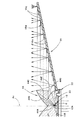
図13および14は、本変形例に係る透光部材84を示す、図1および3と同様の図である。
【0073】
これらの図に示すように、この透光部材84は、その表面に直射部84Fが形成されている点で、上記実施形態の透光部材14と異なっている。
【0074】
この直射部84Fは、光軸Axを中心とする小径領域に形成されており、透光部材84に入射した小角度入射光のうち光軸Axの近傍領域に入射した光を前方へ透過させるようになっている。この直射部84Fは球面状に形成されており、その曲率は光入射用凹部84Aの球状部84A1と略同じ値に設定されている。そしてこれにより、この直射部84Fに対して発散光として入射するLED出射光を光軸Ax寄りにやや集光させるようにして所定の拡散角度で出射させるようになっている。この拡散角度は、リフレクタ16の反射面16aの各反射素子16sの拡散角度と略同じ値に設定されている。
【0075】
この直射部84Fが形成されたことに伴って、透光部材84は上記実施形態の透光部材14よりも幾分大径で形成されており、内面反射部84Bおよび屈折部84Cの形状も多少変更されている。そしてこれにより、LED出射光を略平行光としてリフレクタ16の反射面16aの全領域に入射させるという内面反射部84Bおよび屈折部84Cとしての機能を維持するようになっている。
なお、この透光部材84の光入射用凹部84A、円筒状外周部84Dおよび環状平面部84Eについては、上記実施形態の構成と略同様である。
【0076】
図15は、本変形例に係る透光部材84を備えた車両用灯具を、そのLED光源12を点灯させた状態で示す正面図である。
【0077】
図示のように、この車両用灯具を正面方向から観察したとき、リフレクタ16の反射面16aのみならず、透光部材84の直射部84Fも光輝部Bとして光って見える。その際、直射部84Fの中央部分と反射面16aを構成する各反射素子16sの中央部分とが同時に散点的に光って見える。そして、灯具正面方向から視点を多少ずらした場合においても、直射部84Fおよび各反射素子16sは視点移動量に応じてその中央部分からずれた部分が光輝部Bとして光って見える。
次に、上記実施形態の第10変形例について説明する。
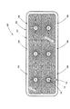
図16は、本変形例に係る車両用灯具60を示す正面図である。
【0078】
この車両用灯具60は、ランプボディ62と、素通し状の透光カバー64とで構成される灯室内に、複数(6個)のリフレクタユニット66が収容されてなっている。
【0079】
これら各リフレクタユニット66は、LED光源72と、透光部材74と、リフレクタ76とを備えてなっている。これらLED光源72、透光部材74およびリフレクタ76は、上記実施形態に係る車両用灯具10のLED光源12、透光部材14およびリフレクタ16と同様の構成となっているが、リフレクタ76の外形形状は、横長略矩形状に設定されている。
そして、これら複数のリフレクタユニット66は、灯具正面視においてリフレクタ76の外周縁部を重複させるようにして上下2段で配置されている。
【0080】
本変形例の灯具構成を採用した場合には、車両用灯具60の明るさを十分に確保することができる。
【0081】
なお、各リフレクタユニット66のリフレクタ76の外形形状は、図示のような横長略矩形状以外の形状を採用することも可能であり、これによりリフレクタユニット66の配列を灯具形状等に応じて自由に設定することが可能である。
【0082】
上記実施形態および各変形例においては、車両用灯具10、60がテールランプである場合について説明したが、これ以外の車両用灯具(例えば、ストップランプ、テール&ストップランプ、クリアランスランプ、ターンシグナルランプ等)である場合においても、上記実施形態および各変形例と同様の構成を採用することにより、これらと同様の作用効果を得ることができる。
【図面の簡単な説明】
【図1】本願発明の一実施形態に係る車両用灯具を示す正面図
【図2】図1のII−II 線断面図
【図3】図2の要部詳細図
【図4】上記車両用灯具を点灯状態で示す正面図
【図5】上記実施形態の第1変形例に係るリフレクタを示す、図3と同様の図
【図6】上記実施形態の第2変形例に係るリフレクタを示す、図3と同様の図
【図7】上記実施形態の第3変形例に係る透光部材を示す、図3と同様の図
【図8】上記実施形態の第4変形例に係る透光部材を示す、図3と同様の図
【図9】上記実施形態の第5変形例に係る透光部材を示す、図3と同様の図
【図10】上記実施形態の第6変形例に係る透光部材を示す、図3と同様の図
【図11】上記実施形態の第7変形例に係るリフレクタを示す、図4と同様の図
【図12】上記実施形態の第8変形例に係るリフレクタを示す、図4と同様の図
【図13】上記実施形態の第9変形例に係る透光部材を示す、図1と同様の図
【図14】上記第9変形例に係る透光部材を示す、図3と同様の図
【図15】上記第9変形例に係る透光部材を示す、図4と同様の図
【図16】上記実施形態の第10変形例に係る車両用灯具を示す正面図
【符号の説明】
10 車両用灯具
12 LED光源
12A LED本体
12B 封止樹脂
14 透光部材
14A 光入射用凹部
14A1 球状部
14A2 円筒部
14B 内面反射部
14C 屈折部
14D 円筒状外周部
14E 環状平面部
16 リフレクタ
16a 反射面
16g 段差部
16s 反射素子
18 透光カバー
20 基板
22 基板支持部材
24、34、44、54、84 透光部材
24A、34A、44A、84A 光入射用凹部
24A1 第1球状部
24A2 第2球状部
24B、34B、44B、54B、84B 内面反射部
24C、34C、44C、54C、84C 屈折部
24D、34D、44D、54D、84D 円筒状外周部
24E、34E、44E、54E、84E 環状平面部
26、36 リフレクタ
26A 通常リフレクタ部
26Aa、26Ba、36Aa、36Ba 反射面
26Ag、26Bg、36Ag、36Bg 段差部
26As、26Bs、36As、36Bs 反射素子
26B、36A、36B 内面反射リフレクタ部
40 充填剤
46、56 リフレクタ
46a、56a 反射面
46g、56g 段差部
46s、56s 反射素子
60 車両用灯具
62 ランプボディ
64 透光カバー
66 リフレクタユニット
72 LED光源
74 透光部材
76 リフレクタ
84A1 球状部
84A2 円筒部
84F 直射部
Ax 光軸
B 光輝部
O 発光中心[0001]
TECHNICAL FIELD OF THE INVENTION
TECHNICAL FIELD The present invention relates to a vehicular lamp provided with an LED (light emitting diode) light source.
[0002]
[Prior art]
2. Description of the Related Art In recent years, vehicular lamps equipped with LED light sources have been widely used. At that time, Patent Document 1 discloses that a light from an LED light source disposed forward of a lamp is made incident on a light transmitting member, and light from the LED light source transmitted through the light transmitting member is transmitted to the light transmitting member. There is described a vehicle lamp configured to reflect forward of the lamp by a reflector formed integrally with the lamp.
[0003]
By employing such a lamp configuration, light from the LED light source can be efficiently used as reflector reflected light.
[0004]
[Patent Document 1]
Japanese Utility Model Publication No. 61-153201
[Problems to be solved by the invention]
However, in the vehicle lamp described in Patent Document 1, the direction of light incident on the reflecting surface of the reflector is different at each portion of the reflecting surface. For this reason, when the reflector is observed from the front of the lamp, it is not easy to form the reflection surface so that the reflection surface can be seen shining over the entire area, and in order to realize this, the depth dimension of the reflector must be increased to some extent. There is a problem that it is necessary to do.
[0005]
The present invention has been made in view of such circumstances, and in a vehicle lamp provided with an LED light source, the reflector is made thinner so that the entire reflection surface thereof can be seen to shine. It is an object of the present invention to provide a vehicular lamp capable of performing the following.
[0006]
[Means for Solving the Problems]
The present invention is intended to achieve the above object by devising the shape of the light transmitting member.
That is, the vehicle lamp according to the present invention is:
An LED light source arranged toward the front of the lamp, a translucent member arranged to allow light from the LED light source to enter, and reflecting the light from the LED light source transmitted through the translucent member toward the front of the lamp. And a reflector arranged as described above,
On the surface of the light-transmitting member, an internal reflection portion for internally reflecting small-angle incident light incident on the light-transmitting member at a small angle with respect to the optical axis of the LED light source in a direction substantially orthogonal to the optical axis; And a refracting portion for refracting the large-angle incident light incident on the light transmitting member at a large angle with respect to the optical axis in a direction substantially orthogonal to the optical axis.
[0007]
The "vehicle lamp" is not limited to a specific type of vehicle lamp, and for example, a tail lamp, a stop lamp, and the like can be adopted.
[0008]
The material of the “light transmitting member” is not particularly limited as long as it is a member having a light transmitting property. For example, a member made of a transparent synthetic resin, a member made of glass, or the like is used. It is possible. Further, the specific shapes of the “internal reflection portion” and the “refraction portion” of the light transmitting member are not particularly limited.
[0009]
As long as the "reflector" is arranged so as to reflect the light from the LED light source transmitted through the translucent member toward the front of the lamp, the specific reflection surface shape and the like are not particularly limited. The “reflector” may be a normal reflector configured to reflect light from an LED light source on an outer surface thereof, or may be a reflector configured by a transparent member. May be configured to internally reflect light from the LED light source that has passed through. In the latter case, the reflector may be formed separately from the light transmitting member, or a part of the reflector may be formed integrally with the light transmitting member.
[0010]
Operation and Effect of the Invention
As shown in the above configuration, the vehicular lamp according to the present invention makes the light from the LED light source disposed toward the front of the lamp enter the light transmitting member, and emits the light from the LED light source transmitted through the light transmitting member. The reflector is configured to reflect the light forward of the lamp. On the surface of the light-transmitting member, the small-angle incident light incident on the light-transmitting member at a small angle with respect to the optical axis of the LED light source is provided on the optical axis. And an internal reflection portion for internal reflection in a direction substantially perpendicular to the optical axis, and a refraction portion for refracting large-angle incident light incident on the light transmitting member at a large angle with respect to the optical axis in a direction substantially orthogonal to the optical axis. Since the light source is formed, the light from the LED light source can be incident on the reflecting surface of the reflector as substantially parallel light traveling in a direction substantially perpendicular to the optical axis.
[0011]
Therefore, the light from the LED light source can be made incident on the peripheral portion of the reflection surface without increasing the depth dimension of the reflector. Further, since the light from the LED light source is incident on the reflecting surface of the reflector as substantially parallel light, it is possible to easily perform the reflection control by the reflector.
[0012]
Therefore, according to the invention of the present application, in a vehicular lamp provided with an LED light source, the reflector can be made thinner, and the entire reflection surface can be made to look shining. Thus, the appearance of the lamp can be improved.
[0013]
In the above configuration, the inner reflecting portion of the light transmitting member is formed of a substantially funnel-shaped rotating curved surface centered on the optical axis, and the refracting portion of the light transmitting member is formed as a substantially annular dome centered on the optical axis. The following operation and effect can be obtained by using a rotating curved surface having the shape of a circle.
[0014]
That is, the light from the LED light source can be incident on the reflecting surface of the reflector as substantially parallel light traveling in a direction substantially orthogonal to the optical axis over the entire circumference of the optical axis. Can be secured. Moreover, since the LED light source can be arranged at the center of the lamp, the external shape of the lamp can be freely set.
[0015]
Further, in the above configuration, the reflecting surface of the reflector is configured to include a plurality of reflecting elements for reflecting light from the LED light source transmitted through the light transmitting member toward the front of the lamp, and these reflecting elements are substantially orthogonal to the optical axis. By arranging the lamp in a stepped manner through a step extending in the direction, the lamp can be made thinner, and the reflecting surface of the reflector can be made to appear almost uniformly scattered throughout the entire area. it can. In this case, each “reflection element” may have a surface shape that reflects light from the LED light source so as to simply deflect the light forward, or deflects the light from the LED light source forward and diffuses the light. It may be configured with a surface shape that reflects light.
[0016]
Further, in the above configuration, if at least a part of the reflection surface of the reflector is configured to reflect light from the LED light source transmitted through the light transmitting member toward the front of the lamp by internal reflection, the lamp is more compact by the thickness of the reflector. Can be configured.
[0017]
Further, in the above configuration, if the direct light portion that transmits the light incident on the area near the optical axis out of the small-angle incident light on the surface of the light transmitting member is formed, if only the reflection surface of the reflector is provided, Instead, the direct light portion of the translucent member can also be made to look shining, so that the appearance of the lamp can be further improved.
[0018]
By the way, the vehicle lamp according to the present invention may be configured to include only one set of the LED light source, the light transmitting member, and the reflector, or may be configured to include a plurality of sets of the LED light source, the light transmitting member, and the reflector. When the latter configuration is adopted, the brightness of the vehicle lamp can be further increased. At this time, in the present invention, since the outer shape of the reflector can be freely set, it is also possible to freely arrange these plural sets of LED light sources, light transmitting members and reflectors according to the shape of the lamp. It becomes.
[0019]
BEST MODE FOR CARRYING OUT THE INVENTION
Hereinafter, an embodiment of the present invention will be described with reference to the drawings.
[0020]
1 is a front view showing a vehicular lamp according to the present embodiment, FIG. 2 is a sectional view taken along line II-II of FIG. 1, and FIG. 3 is a detailed view of a main part of FIG.
[0021]
As shown in these drawings, a
[0022]
The
[0023]
The
[0024]
On the rear surface of the
[0025]
On the surface of the
[0026]
The inner
[0027]
The portion of the surface of the
[0028]
The
[0029]
The reflecting
[0030]
Each of the reflecting
[0031]
The
FIG. 4 is a front view showing the
[0032]
As shown in the drawing, when the
[0033]
Even when the viewpoint is slightly shifted from the front direction of the lamp, since the LED emission light is incident on each of the
[0034]
As described in detail above, the
[0035]
For this reason, it is possible to make the LED outgoing light enter the periphery of the
[0036]
Therefore, according to the present embodiment, the thickness of the
[0037]
In particular, in the present embodiment, the
[0038]
That is, the LED emission light can be made to enter the reflecting
[0039]
Further, in the present embodiment, the reflecting
[0040]
In the present embodiment, each reflecting
Next, a first modification of the above embodiment will be described.
FIG. 5 is a view similar to FIG. 3, showing the
[0041]
As shown in the figure, the
[0042]
The
[0043]
On the other hand, the internal reflection reflector unit 26B is configured to reflect the LED emission light transmitted through the
[0044]
Also in the case of adopting the configuration of the present modification, as in the case of the above-described embodiment, the thickness of the
[0045]
Moreover, when the configuration of the present modification is adopted, the inner reflection reflector 26B is smaller than the outer periphery of the
[0046]
Further, in the present modification, since the inner-surface reflecting reflector portion 26B is formed of a transparent member, it is possible to produce a sense of transparency (crystal feeling) particularly with respect to the appearance when the
Next, a second modification of the above embodiment will be described.
FIG. 6 is a view similar to FIG. 3, showing the
[0047]
As shown in the drawing, the
[0048]
On the other hand, in the
[0049]
Also in the case where the configuration of this modification is adopted, as in the case of the above-described embodiment, the thickness of the
[0050]
Moreover, when the configuration of the present modification is adopted, the
[0051]
Further, in the present modification, since the
Next, a third modification of the above embodiment will be described.
FIG. 7 is a view similar to FIG. 3, showing the
[0052]
As illustrated, the
[0053]
That is, the light incident
[0054]
On the surface of the
[0055]
Also in the case where the configuration of the present modification is adopted, similarly to the case of the above-described embodiment, the LED emission light can be incident on the
[0056]
Moreover, in the case of employing the configuration of this modification, since the LED emission light goes straight in the
Next, a fourth modification of the above embodiment will be described.
FIG. 8 is a view similar to FIG. 3, showing the
[0057]
As shown, the
[0058]
That is, the light incident
[0059]
The inner reflecting portion 34B, the refracting
Even when the configuration of this modification is adopted, the same operation and effect as those of the third modification can be obtained.
[0060]
Moreover, in the present modification, the
Next, a fifth modification of the above embodiment will be described.
FIG. 9 is a view similar to FIG. 3, showing a
[0061]
As shown in the figure, the
[0062]
That is, the
[0063]
The
Even when the configuration of this modification is adopted, the same operation and effect as those of the third modification can be obtained.
[0064]
Moreover, in this modification, the light-transmitting
Next, a sixth modification of the above embodiment will be described.
FIG. 10 is a view similar to FIG. 3, showing the
[0065]
As shown in the figure, the
[0066]
The
Even when the configuration of this modification is adopted, the same operation and effect as those of the third modification can be obtained.
[0067]
Moreover, in this modification, the
Next, seventh and eighth modifications of the above embodiment will be described.
[0068]
FIGS. 11 and 12 are views similar to FIG. 4 showing the
[0069]
As shown in these figures, the
[0070]
That is, in each of the
[0071]
Note that each of the
[0072]
When the
Next, a ninth modification of the above embodiment will be described.
FIGS. 13 and 14 are views similar to FIGS. 1 and 3, showing a
[0073]
As shown in these drawings, the
[0074]
The
[0075]
With the formation of the
The light incident
[0076]
FIG. 15 is a front view showing a vehicle lamp provided with the
[0077]
As shown in the figure, when the vehicle lamp is observed from the front, not only the
Next, a tenth modification of the above embodiment will be described.
FIG. 16 is a front view showing a
[0078]
In the
[0079]
Each of these
The plurality of
[0080]
When the lamp configuration of the present modification is adopted, the brightness of the
[0081]
In addition, the outer shape of the
[0082]
In the above-described embodiment and each modified example, the case where the
[Brief description of the drawings]
FIG. 1 is a front view showing a vehicle lamp according to an embodiment of the present invention.
FIG. 2 is a sectional view taken along line II-II of FIG.
FIG. 3 is a detailed view of a main part of FIG. 2;
FIG. 4 is a front view showing the vehicle lamp in a lighting state;
FIG. 5 is a view similar to FIG. 3, showing a reflector according to a first modification of the embodiment.
FIG. 6 is a view similar to FIG. 3, showing a reflector according to a second modification of the embodiment.
FIG. 7 is a view similar to FIG. 3, showing a translucent member according to a third modification of the embodiment.
FIG. 8 is a view similar to FIG. 3, showing a translucent member according to a fourth modification of the embodiment.
FIG. 9 is a view similar to FIG. 3, showing a translucent member according to a fifth modification of the embodiment.
FIG. 10 is a view similar to FIG. 3, showing a translucent member according to a sixth modification of the embodiment.
FIG. 11 is a view similar to FIG. 4, showing a reflector according to a seventh modification of the embodiment.
FIG. 12 is a view similar to FIG. 4, showing a reflector according to an eighth modification of the embodiment.
FIG. 13 is a view similar to FIG. 1, showing a translucent member according to a ninth modification of the embodiment.
FIG. 14 is a view similar to FIG. 3, showing a translucent member according to the ninth modification.
FIG. 15 is a view similar to FIG. 4, showing a translucent member according to the ninth modification.
FIG. 16 is a front view showing a vehicle lamp according to a tenth modification of the embodiment.
[Explanation of symbols]
10 Vehicle lighting fixtures
12 LED light source
12A LED body
12B sealing resin
14 Translucent member
14A recess for light incidence
14A1 bulb
14A2 cylindrical part
14B Internal reflection part
14C refraction section
14D cylindrical outer periphery
14E annular flat part
16 Reflector
16a reflective surface
16g step
16s reflective element
18 Transparent cover
20 substrates
22 Substrate support member
24, 34, 44, 54, 84 translucent member
24A, 34A, 44A, 84A Light incidence recess
24A1 First bulb
24A2 2nd spherical part
24B, 34B, 44B, 54B, 84B Internal reflection part
24C, 34C, 44C, 54C, 84C Refractor
24D, 34D, 44D, 54D, 84D Cylindrical outer periphery
24E, 34E, 44E, 54E, 84E Annular flat part
26, 36 reflector
26A Normal reflector part
26Aa, 26Ba, 36Aa, 36Ba Reflective surface
26Ag, 26Bg, 36Ag, 36Bg Step
26As, 26Bs, 36As, 36Bs reflective element
26B, 36A, 36B Internal reflection reflector
40 filler
46, 56 reflector
46a, 56a reflective surface
46g, 56g Step
46s, 56s reflective element
60 Vehicle lighting fixtures
62 lamp body
64 Transparent cover
66 Reflector unit
72 LED light source
74 translucent member
76 Reflector
84A1 bulb
84A2 cylindrical part
84F direct irradiation part
Ax optical axis
B shining part
O emission center
Claims (6)
上記透光部材の表面に、上記LED光源の光軸に対して小角度で該透光部材に入射した小角度入射光を上記光軸と略直交する方向へ内面反射させる内面反射部と、上記光軸に対して大角度で該透光部材に入射した大角度入射光を上記光軸と略直交する方向へ屈折させる屈折部とが形成されている、ことを特徴とする車両用灯具。An LED light source arranged toward the front of the lamp, a translucent member arranged to allow light from the LED light source to enter, and reflecting the light from the LED light source transmitted through the translucent member toward the front of the lamp. And a reflector arranged as described above,
On the surface of the light-transmitting member, an internal reflection portion for internally reflecting small-angle incident light incident on the light-transmitting member at a small angle with respect to the optical axis of the LED light source in a direction substantially orthogonal to the optical axis; A vehicular lamp having a refraction portion for refracting large-angle incident light incident on the light transmitting member at a large angle with respect to the optical axis in a direction substantially orthogonal to the optical axis.
Priority Applications (7)
| Application Number | Priority Date | Filing Date | Title |
|---|---|---|---|
| JP2003160330A JP4153370B2 (en) | 2002-07-04 | 2003-06-05 | Vehicle lighting |
| KR10-2003-0044266A KR100524500B1 (en) | 2002-07-04 | 2003-07-01 | Vehicle lamp |
| CNB031450644A CN1249374C (en) | 2002-07-04 | 2003-07-02 | Car lamps |
| US10/611,102 US6951415B2 (en) | 2002-07-04 | 2003-07-02 | Vehicle lamp |
| GB0315620A GB2391930B (en) | 2002-07-04 | 2003-07-03 | Vehicle lamp |
| FR0308177A FR2841966B1 (en) | 2002-07-04 | 2003-07-04 | VEHICLE LAMP WITH LOW DEPTH REFLECTOR |
| DE10330261A DE10330261B4 (en) | 2002-07-04 | 2003-07-04 | vehicle light |
Applications Claiming Priority (2)
| Application Number | Priority Date | Filing Date | Title |
|---|---|---|---|
| JP2002196594 | 2002-07-04 | ||
| JP2003160330A JP4153370B2 (en) | 2002-07-04 | 2003-06-05 | Vehicle lighting |
Publications (2)
| Publication Number | Publication Date |
|---|---|
| JP2004087461A true JP2004087461A (en) | 2004-03-18 |
| JP4153370B2 JP4153370B2 (en) | 2008-09-24 |
Family
ID=27759761
Family Applications (1)
| Application Number | Title | Priority Date | Filing Date |
|---|---|---|---|
| JP2003160330A Expired - Fee Related JP4153370B2 (en) | 2002-07-04 | 2003-06-05 | Vehicle lighting |
Country Status (7)
| Country | Link |
|---|---|
| US (1) | US6951415B2 (en) |
| JP (1) | JP4153370B2 (en) |
| KR (1) | KR100524500B1 (en) |
| CN (1) | CN1249374C (en) |
| DE (1) | DE10330261B4 (en) |
| FR (1) | FR2841966B1 (en) |
| GB (1) | GB2391930B (en) |
Cited By (19)
| Publication number | Priority date | Publication date | Assignee | Title |
|---|---|---|---|---|
| JP2004128434A (en) * | 2002-03-20 | 2004-04-22 | Toyoda Gosei Co Ltd | Light emitters and lamps |
| JP2006093711A (en) * | 2004-09-24 | 2006-04-06 | Shogen Koden Kofun Yugenkoshi | Semiconductor light emitting device unit |
| JP2006222413A (en) * | 2005-01-17 | 2006-08-24 | Omron Corp | Luminescent light source and luminescent light source array |
| JP2007087757A (en) * | 2005-09-21 | 2007-04-05 | Sharp Corp | Light guide plate and lighting device |
| JP2008010150A (en) * | 2006-06-26 | 2008-01-17 | Stanley Electric Co Ltd | Lighting device |
| WO2008023797A1 (en) * | 2006-08-25 | 2008-02-28 | The Furukawa Electric Co., Ltd. | Illumination device |
| JP2008053660A (en) * | 2006-08-28 | 2008-03-06 | Matsushita Electric Works Ltd | Light emitting module |
| JP2008522371A (en) * | 2004-11-30 | 2008-06-26 | マグナ インターナショナル インコーポレイテッド | Hybrid optical system for LED lamps |
| JP2008186742A (en) * | 2007-01-31 | 2008-08-14 | Koito Mfg Co Ltd | Vehicle lighting |
| JP2010086889A (en) * | 2008-10-02 | 2010-04-15 | Casio Hitachi Mobile Communications Co Ltd | Curved light guide, lighting device, and electronic device |
| JP2010528414A (en) * | 2007-05-23 | 2010-08-19 | コーニンクレッカ フィリップス エレクトロニクス エヌ ヴィ | Automotive lighting equipment |
| JP2011240030A (en) * | 2010-05-20 | 2011-12-01 | Kyoraku Sangyo Kk | Light guide, illumination unit, game board unit, and pachinko game machine |
| JP2011253154A (en) * | 2010-06-04 | 2011-12-15 | Kyoraku Sangyo Co Ltd | Light guide body, illumination unit, game board unit, and pachinko game machine |
| JP2012069363A (en) * | 2010-09-22 | 2012-04-05 | Stanley Electric Co Ltd | Bulb-compatible type led lamp |
| JP2012069321A (en) * | 2010-09-22 | 2012-04-05 | Koito Mfg Co Ltd | Vehicular lamp fitting |
| JP2012511244A (en) * | 2008-12-08 | 2012-05-17 | オスラム オプト セミコンダクターズ ゲゼルシャフト ミット ベシュレンクテル ハフツング | LED lighting device with uniform light density and reduced blind action |
| JP2017123286A (en) * | 2016-01-08 | 2017-07-13 | 三菱電機株式会社 | Light source device and luminaire |
| JP2021034340A (en) * | 2019-08-29 | 2021-03-01 | 株式会社小糸製作所 | Identification lamp for vehicle |
| JP2021072234A (en) * | 2019-11-01 | 2021-05-06 | スタンレー電気株式会社 | Vehicular lamp |
Families Citing this family (118)
| Publication number | Priority date | Publication date | Assignee | Title |
|---|---|---|---|---|
| JP4162935B2 (en) * | 2002-07-04 | 2008-10-08 | 株式会社小糸製作所 | Vehicle lighting |
| DE10249113B4 (en) * | 2002-10-22 | 2010-04-08 | Odelo Gmbh | Vehicle lamp, in particular tail lamp, preferably for motor vehicles |
| FR2846400B1 (en) * | 2002-10-28 | 2005-10-07 | Valeo Vision | SIGNALING LIGHT COMPRISING A DEVICE FOR RECOVERING AND DISTRIBUTING THE LUMINOUS FLOW TO AN ANNULAR REFLECTOR |
| DE102004015544B4 (en) * | 2003-03-31 | 2009-05-07 | Toyoda Gosei Co., Ltd. | LED light and side mirror device |
| JP4044024B2 (en) * | 2003-09-29 | 2008-02-06 | 株式会社小糸製作所 | Vehicle headlamp |
| FR2866412B1 (en) * | 2004-02-13 | 2007-01-19 | Valeo Vision | LUMINOUS PROJECTOR MODULE FOR A MOTOR VEHICLE, REFLECTOR FOR SUCH A MODULE, AND PROJECTOR EQUIPPED WITH A MODULE |
| FR2867257B1 (en) * | 2004-03-05 | 2007-01-05 | Valeo Vision | SIGNALING AND / OR LIGHTING DEVICE FOR A MOTOR VEHICLE COMPRISING A DIOPTRIC ELEMENT |
| JP4335719B2 (en) * | 2004-03-19 | 2009-09-30 | スタンレー電気株式会社 | Vehicle lighting |
| EP2930417A1 (en) * | 2004-06-24 | 2015-10-14 | Valeo Vision | Lighting and/or signalling device with optical waveguide |
| ES1058053Y (en) * | 2004-07-14 | 2005-02-01 | Fed Signal Vama Sa | INTERNAL REFLECTION COLIMATOR LENS |
| US7118262B2 (en) * | 2004-07-23 | 2006-10-10 | Cree, Inc. | Reflective optical elements for semiconductor light emitting devices |
| TWI249257B (en) | 2004-09-24 | 2006-02-11 | Epistar Corp | Illumination apparatus |
| KR100677136B1 (en) * | 2004-09-25 | 2007-02-02 | 삼성전자주식회사 | Backlight unit and LCD using the same |
| US8541795B2 (en) * | 2004-10-12 | 2013-09-24 | Cree, Inc. | Side-emitting optical coupling device |
| KR100754169B1 (en) | 2004-11-24 | 2007-09-03 | 삼성전자주식회사 | Side light emitting device, backlight unit using same as light source, and liquid crystal display device employing same |
| DE102004063111B4 (en) * | 2004-12-22 | 2011-04-28 | Odelo Gmbh | Light unit with light source, light guide body and light deflection area |
| CN100452459C (en) * | 2005-01-17 | 2009-01-14 | 欧姆龙株式会社 | Luminous light source and its array, light path setting method and light emitting method |
| US7275849B2 (en) * | 2005-02-25 | 2007-10-02 | Visteon Global Technologies, Inc. | LED replacement bulb |
| DE102005032650A1 (en) * | 2005-07-13 | 2007-02-01 | Hella Kgaa Hueck & Co. | Lamp for vehicles |
| DE102005043992B4 (en) * | 2005-09-14 | 2010-04-08 | Automotive Lighting Reutlingen Gmbh | Signal light of a vehicle |
| US7420173B2 (en) * | 2005-10-31 | 2008-09-02 | Ford Global Technologies, Inc. | Reflective collimation optic |
| US7334933B1 (en) * | 2005-11-04 | 2008-02-26 | Simon Jerome H | Unified optical collection and distribution of light from quasi-point sources including LEDs, and linear light sources |
| RU2303800C1 (en) * | 2005-12-15 | 2007-07-27 | Самсунг Электроникс Ко., Лтд. | Lens for forming radiating light diode |
| US20070200118A1 (en) * | 2005-12-21 | 2007-08-30 | Epstein Kenneth A | Led light confinement element |
| FR2896850A1 (en) | 2006-01-30 | 2007-08-03 | Peugeot Citroen Automobiles Sa | REFLECTOR FOR VEHICLE LIGHTS |
| US7909496B2 (en) * | 2006-02-01 | 2011-03-22 | Koninklijke Philips Electronics N.V. | Lighting system for creating an illuminated surface |
| TWI281556B (en) * | 2006-03-15 | 2007-05-21 | Bright Led Electronics Corp | Lens, light-emitting apparatus with lens and its manufacturing method |
| ITRE20060052A1 (en) * | 2006-04-28 | 2007-10-29 | Incerti Simonini Snc | SECONDARY OPTICAL DEVICE FOR LEDS LAMPS |
| JP2007325884A (en) * | 2006-06-09 | 2007-12-20 | Aruze Corp | Game machine |
| JP2007325879A (en) * | 2006-06-09 | 2007-12-20 | Aruze Corp | Game machine |
| DE102006034070A1 (en) * | 2006-07-20 | 2008-01-31 | Schefenacker Vision Systems Germany Gmbh | Light unit with a light-emitting diode with integrated Lichtumlenkkörper |
| JP2008097848A (en) * | 2006-10-06 | 2008-04-24 | Ichikoh Ind Ltd | Vehicle lighting |
| JP4631838B2 (en) | 2006-10-20 | 2011-02-16 | 市光工業株式会社 | Vehicle lighting |
| US20090067175A1 (en) * | 2007-01-04 | 2009-03-12 | Bright Led Electronics Corp. | Lens for use with a light-emitting element and light source device including the lens |
| ITGE20070073A1 (en) * | 2007-07-31 | 2009-02-01 | Giorgio Gai | RADIANT ELEMENT FOR LUMINOUS PANELS AND BRIGHT PANEL MADE WITH SUCH A RADIANT ELEMENT |
| BRPI0808993B1 (en) * | 2007-03-16 | 2018-12-04 | Cabot Corp | airgel particle manufacturing method |
| JP5349453B2 (en) * | 2007-04-05 | 2013-11-20 | コーニンクレッカ フィリップス エヌ ヴェ | Light beam shaper |
| US7554742B2 (en) * | 2007-04-17 | 2009-06-30 | Visteon Global Technologies, Inc. | Lens assembly |
| CA2685906C (en) * | 2007-05-02 | 2015-11-24 | Luminator Holding, L.P. | Lighting method and system |
| CN101368686B (en) * | 2007-08-14 | 2011-06-29 | 富士迈半导体精密工业(上海)有限公司 | Light source assembly and its light guide plate, and backlight module |
| CN101382698B (en) * | 2007-09-06 | 2012-01-11 | 富士迈半导体精密工业(上海)有限公司 | Backlight module unit |
| US8506132B2 (en) * | 2007-10-04 | 2013-08-13 | Dragonfish Technologies Llc | Method and apparatus for creating high efficiency radial circular lighting distributions from a hemispherical lambertian source |
| US7703950B2 (en) * | 2007-11-21 | 2010-04-27 | C-R Control Systems, Inc. | Side-emitting lens for LED lamp |
| DE102008007723A1 (en) * | 2008-02-06 | 2009-08-20 | Osram Gesellschaft mit beschränkter Haftung | Lighting module, luminaire and method for lighting |
| WO2009110011A1 (en) * | 2008-03-03 | 2009-09-11 | Datasensor S.P.A. | Optical system for mixing the light emitted by a plurality of light sources |
| US7766509B1 (en) | 2008-06-13 | 2010-08-03 | Lumec Inc. | Orientable lens for an LED fixture |
| US8002435B2 (en) * | 2008-06-13 | 2011-08-23 | Philips Electronics Ltd Philips Electronique Ltee | Orientable lens for an LED fixture |
| CA2738315C (en) | 2008-09-24 | 2017-01-03 | Luminator Holding Lp | Methods and systems for maintaining the illumination intensity of light emitting diodes |
| US8235556B2 (en) * | 2008-10-20 | 2012-08-07 | Reflexite Corporation | Condensing element, array, and methods thereof |
| GB2464919B (en) * | 2008-10-22 | 2011-01-12 | Chia-Mao Li | anti-glare lighting device using light emitting diode |
| US8858032B2 (en) | 2008-10-24 | 2014-10-14 | Cree, Inc. | Lighting device, heat transfer structure and heat transfer element |
| JP5442321B2 (en) * | 2009-01-27 | 2014-03-12 | 株式会社小糸製作所 | Vehicle lighting |
| US8246212B2 (en) * | 2009-01-30 | 2012-08-21 | Koninklijke Philips Electronics N.V. | LED optical assembly |
| JP5369359B2 (en) * | 2009-04-13 | 2013-12-18 | スタンレー電気株式会社 | Lamp |
| US8033693B2 (en) * | 2009-04-30 | 2011-10-11 | Avago Technologies Ecbu Ip (Singapore) Pte. Ltd. | Lighting structure with multiple reflective surfaces |
| DE102009021182A1 (en) | 2009-05-13 | 2010-11-18 | Hella Kgaa Hueck & Co. | Lighting device for roads |
| US9841162B2 (en) | 2009-05-18 | 2017-12-12 | Cree, Inc. | Lighting device with multiple-region reflector |
| DE202009007292U1 (en) | 2009-05-20 | 2010-10-07 | Hella Kgaa Hueck & Co. | Lighting device for roads |
| NL1037224C2 (en) * | 2009-08-25 | 2011-02-28 | Spanninga Metaal | REAR WHEEL AND BACKLIGHT FOR A REAR WHEEL. |
| WO2011032006A1 (en) * | 2009-09-14 | 2011-03-17 | Bridgelux, Inc. | Extended source light module |
| JP5023134B2 (en) * | 2009-10-27 | 2012-09-12 | 株式会社遠藤照明 | LED light distribution lens, LED illumination module including the LED light distribution lens, and lighting fixture including the LED illumination module |
| DE102009056385A1 (en) | 2009-11-30 | 2011-06-01 | Osram Gesellschaft mit beschränkter Haftung | Luminaire and traffic route lighting device |
| KR101117305B1 (en) * | 2009-12-04 | 2012-03-20 | 주식회사 세 바 | Reflector structure of car using Light Emitting Diode |
| KR101241678B1 (en) * | 2010-06-30 | 2013-03-11 | 현대자동차주식회사 | Rear lamp for vehicle |
| KR101380256B1 (en) * | 2010-07-26 | 2014-04-01 | 현대모비스 주식회사 | Oled element of rear lamp for motors |
| US10883702B2 (en) | 2010-08-31 | 2021-01-05 | Ideal Industries Lighting Llc | Troffer-style fixture |
| WO2012042436A1 (en) * | 2010-09-29 | 2012-04-05 | Koninklijke Philips Electronics N.V. | Tir optics with optimized incoupling structure |
| CN101963316B (en) * | 2010-10-28 | 2012-07-18 | 鸿富锦精密工业(深圳)有限公司 | Led ceiling lamp |
| US9581312B2 (en) * | 2010-12-06 | 2017-02-28 | Cree, Inc. | LED light fixtures having elongated prismatic lenses |
| US8523376B2 (en) | 2010-12-06 | 2013-09-03 | John D. Motyka | Self-defense walking aid |
| US9494293B2 (en) | 2010-12-06 | 2016-11-15 | Cree, Inc. | Troffer-style optical assembly |
| DE102011018508C5 (en) * | 2011-04-23 | 2016-06-30 | Automotive Lighting Reutlingen Gmbh | Optical fiber element arrangement and motor vehicle lighting device with such a light guide element arrangement |
| JP6072785B2 (en) | 2011-07-01 | 2017-02-01 | フィリップス ライティング ホールディング ビー ヴィ | Optical waveguide |
| US10823347B2 (en) | 2011-07-24 | 2020-11-03 | Ideal Industries Lighting Llc | Modular indirect suspended/ceiling mount fixture |
| DE102011053032B4 (en) | 2011-08-26 | 2022-06-09 | HELLA GmbH & Co. KGaA | Lighting unit for vehicles with a lens covering the housing |
| US10544925B2 (en) | 2012-01-06 | 2020-01-28 | Ideal Industries Lighting Llc | Mounting system for retrofit light installation into existing light fixtures |
| US9777897B2 (en) | 2012-02-07 | 2017-10-03 | Cree, Inc. | Multiple panel troffer-style fixture |
| JP5897919B2 (en) * | 2012-02-07 | 2016-04-06 | 株式会社小糸製作所 | Vehicle lighting |
| US9494294B2 (en) | 2012-03-23 | 2016-11-15 | Cree, Inc. | Modular indirect troffer |
| US9310038B2 (en) | 2012-03-23 | 2016-04-12 | Cree, Inc. | LED fixture with integrated driver circuitry |
| US9874322B2 (en) | 2012-04-10 | 2018-01-23 | Cree, Inc. | Lensed troffer-style light fixture |
| ITMI20121399A1 (en) * | 2012-08-07 | 2014-02-08 | Artemide Spa | LED LIGHTING LAMP |
| US10648643B2 (en) | 2013-03-14 | 2020-05-12 | Ideal Industries Lighting Llc | Door frame troffer |
| US9595627B2 (en) | 2013-03-15 | 2017-03-14 | John Paul Morgan | Photovoltaic panel |
| US9052075B2 (en) | 2013-03-15 | 2015-06-09 | Cree, Inc. | Standardized troffer fixture |
| US9347825B2 (en) | 2013-03-15 | 2016-05-24 | Ford Global Technologies, Llc | Vehicle lamps with uniform apparent brightness |
| US9960303B2 (en) | 2013-03-15 | 2018-05-01 | Morgan Solar Inc. | Sunlight concentrating and harvesting device |
| US9464783B2 (en) | 2013-03-15 | 2016-10-11 | John Paul Morgan | Concentrated photovoltaic panel |
| US9714756B2 (en) | 2013-03-15 | 2017-07-25 | Morgan Solar Inc. | Illumination device |
| TW201447178A (en) * | 2013-06-06 | 2014-12-16 | Tyc Brother Ind Co Ltd | Light guiding lens |
| DE202013005301U1 (en) | 2013-06-11 | 2013-07-25 | T.Y.C. Brother Industrial Co., Ltd. | Uniform luminaire lens for vehicles |
| CN104296067B (en) * | 2013-07-16 | 2017-12-01 | 堤维西交通工业股份有限公司 | Light guide lens |
| USD786471S1 (en) | 2013-09-06 | 2017-05-09 | Cree, Inc. | Troffer-style light fixture |
| DE102013222481A1 (en) | 2013-11-06 | 2015-05-07 | Zumtobel Lighting Gmbh | Optical element for a lamp, as well as light |
| DE102013222794A1 (en) * | 2013-11-08 | 2015-05-13 | Automotive Lighting Reutlingen Gmbh | Optical fiber, optical fiber structure and automotive lighting device |
| FR3015002B1 (en) * | 2013-12-17 | 2018-07-13 | Legrand France | LIGHTING DEVICE |
| USD807556S1 (en) | 2014-02-02 | 2018-01-09 | Cree Hong Kong Limited | Troffer-style fixture |
| US10451253B2 (en) | 2014-02-02 | 2019-10-22 | Ideal Industries Lighting Llc | Troffer-style fixture with LED strips |
| USD772465S1 (en) | 2014-02-02 | 2016-11-22 | Cree Hong Kong Limited | Troffer-style fixture |
| US8960951B1 (en) * | 2014-02-14 | 2015-02-24 | Litetronics International, Inc. | LED lamp retrofit system, kit, and method |
| CN103836541B (en) * | 2014-02-24 | 2016-08-17 | 京东方光科技有限公司 | Light guide and parallel light source lighting device |
| US10527225B2 (en) | 2014-03-25 | 2020-01-07 | Ideal Industries, Llc | Frame and lens upgrade kits for lighting fixtures |
| DE202014101954U1 (en) * | 2014-04-25 | 2015-07-28 | Zumtobel Lighting Gmbh | Optical element for an LED, LED arrangement with such an optical element, as well as luminaire with such an LED arrangement |
| AT515802B1 (en) * | 2014-06-11 | 2015-12-15 | Zizala Lichtsysteme Gmbh | Lighting device for a vehicle and vehicle headlights |
| US20170254500A1 (en) | 2014-09-29 | 2017-09-07 | Guido Kellermann Produktentwicklung & Handel E. K. | Vehicle light |
| US10012354B2 (en) | 2015-06-26 | 2018-07-03 | Cree, Inc. | Adjustable retrofit LED troffer |
| CN106958757A (en) * | 2016-01-11 | 2017-07-18 | 法雷奥照明湖北技术中心有限公司 | Illuminating area expanding unit and illumination and/or signal designation equipment |
| DE102016201347B4 (en) * | 2016-01-29 | 2024-09-19 | Zumtobel Lighting Gmbh | Optical system for influencing the light output of a light source |
| CN109099390A (en) * | 2016-06-29 | 2018-12-28 | 深圳市窗科技有限责任公司 | One kind going out photosystem |
| EP3564580B1 (en) * | 2017-02-15 | 2022-02-09 | Opple Lighting Co., Ltd. | Reflection apparatus, light source module and illumination apparatus |
| CN112664909B (en) * | 2017-03-15 | 2023-05-30 | 南京迈瑞生物医疗电子有限公司 | Facula adjusting part, lighting device and operating lamp |
| DE102019115344A1 (en) * | 2019-06-06 | 2020-12-10 | Bartenbach Holding Gmbh | Reflector for a lamp |
| JP2021012760A (en) | 2019-07-03 | 2021-02-04 | ヤマハ発動機株式会社 | Lamp for saddle-riding type vehicle and saddle-riding type vehicle |
| CN111578230A (en) * | 2020-05-22 | 2020-08-25 | 华域视觉科技(上海)有限公司 | Concentrating reflection optical structure for vehicle lamp and LED signal lamp thereof |
| KR20220037645A (en) * | 2020-09-18 | 2022-03-25 | 에스엘 주식회사 | Lamp for vehicle |
| US11656497B2 (en) * | 2021-05-25 | 2023-05-23 | Lextar Electronics Corporation | Light emitting module and optical lens thereof |
| KR20240102652A (en) * | 2022-12-26 | 2024-07-03 | 현대모비스 주식회사 | Lamp |
| DE102024208068A1 (en) * | 2024-08-23 | 2026-02-26 | Volkswagen Aktiengesellschaft | Lighting device for a motor vehicle |
Family Cites Families (15)
| Publication number | Priority date | Publication date | Assignee | Title |
|---|---|---|---|---|
| GB531185A (en) * | 1939-06-29 | 1940-12-31 | George William Rawlings | Improvements in electric lamps |
| US2700098A (en) * | 1948-11-02 | 1955-01-18 | Hartford Nat Bank & Trust Co | Electric lighting fitting |
| JPS61153201U (en) | 1985-03-14 | 1986-09-22 | ||
| JPH02503131A (en) | 1988-02-05 | 1990-09-27 | ナウチノ‐プロイズボドストベンノエ オビエディネニエポ アフトエレクトロニキ イ アフトトラクトルノム エレクトロオボルドバニユ | One-piece collimator |
| US5197792A (en) * | 1992-04-21 | 1993-03-30 | General Motors Corporation | Illuminator device for a display panel |
| JPH0772815A (en) | 1992-12-15 | 1995-03-17 | Koito Mfg Co Ltd | Liquid crystal display device |
| DE19638081A1 (en) * | 1996-09-19 | 1998-03-26 | Hella Kg Hueck & Co | Light for vehicles |
| CA2299543C (en) * | 1997-08-12 | 2008-02-26 | Decoma International Inc. | Bireflective lens element |
| JPH11265606A (en) | 1998-03-18 | 1999-09-28 | Koito Mfg Co Ltd | Vehicle sign lights |
| JP2000057823A (en) * | 1998-08-07 | 2000-02-25 | Koito Mfg Co Ltd | Vehicle sign lights |
| CN1288006C (en) | 2001-03-27 | 2006-12-06 | 梅里迪安机动车系统公司 | Vehicular lamp assembly with a simplified structure and CHMSL and tail lamp incorporating the same |
| US6598998B2 (en) | 2001-05-04 | 2003-07-29 | Lumileds Lighting, U.S., Llc | Side emitting light emitting device |
| JP4565601B2 (en) | 2001-08-31 | 2010-10-20 | スタンレー電気株式会社 | Vehicle lighting |
| DE20206829U1 (en) | 2002-04-30 | 2002-09-05 | Automotive Lighting Reutlingen GmbH, 72762 Reutlingen | Luminaire, in particular position lamp |
| JP2004047220A (en) * | 2002-07-10 | 2004-02-12 | Koito Mfg Co Ltd | Vehicle lighting |
-
2003
- 2003-06-05 JP JP2003160330A patent/JP4153370B2/en not_active Expired - Fee Related
- 2003-07-01 KR KR10-2003-0044266A patent/KR100524500B1/en not_active Expired - Fee Related
- 2003-07-02 CN CNB031450644A patent/CN1249374C/en not_active Expired - Fee Related
- 2003-07-02 US US10/611,102 patent/US6951415B2/en not_active Expired - Fee Related
- 2003-07-03 GB GB0315620A patent/GB2391930B/en not_active Expired - Fee Related
- 2003-07-04 DE DE10330261A patent/DE10330261B4/en not_active Expired - Fee Related
- 2003-07-04 FR FR0308177A patent/FR2841966B1/en not_active Expired - Fee Related
Cited By (22)
| Publication number | Priority date | Publication date | Assignee | Title |
|---|---|---|---|---|
| JP2004128434A (en) * | 2002-03-20 | 2004-04-22 | Toyoda Gosei Co Ltd | Light emitters and lamps |
| JP2006093711A (en) * | 2004-09-24 | 2006-04-06 | Shogen Koden Kofun Yugenkoshi | Semiconductor light emitting device unit |
| JP2008522371A (en) * | 2004-11-30 | 2008-06-26 | マグナ インターナショナル インコーポレイテッド | Hybrid optical system for LED lamps |
| JP2006222413A (en) * | 2005-01-17 | 2006-08-24 | Omron Corp | Luminescent light source and luminescent light source array |
| JP2007087757A (en) * | 2005-09-21 | 2007-04-05 | Sharp Corp | Light guide plate and lighting device |
| JP2008010150A (en) * | 2006-06-26 | 2008-01-17 | Stanley Electric Co Ltd | Lighting device |
| WO2008023797A1 (en) * | 2006-08-25 | 2008-02-28 | The Furukawa Electric Co., Ltd. | Illumination device |
| US8061876B2 (en) | 2006-08-25 | 2011-11-22 | The Furukawa Electric Co., Ltd | Illumination device |
| JP2008053660A (en) * | 2006-08-28 | 2008-03-06 | Matsushita Electric Works Ltd | Light emitting module |
| JP2008186742A (en) * | 2007-01-31 | 2008-08-14 | Koito Mfg Co Ltd | Vehicle lighting |
| JP2010528414A (en) * | 2007-05-23 | 2010-08-19 | コーニンクレッカ フィリップス エレクトロニクス エヌ ヴィ | Automotive lighting equipment |
| JP2010086889A (en) * | 2008-10-02 | 2010-04-15 | Casio Hitachi Mobile Communications Co Ltd | Curved light guide, lighting device, and electronic device |
| JP2012511244A (en) * | 2008-12-08 | 2012-05-17 | オスラム オプト セミコンダクターズ ゲゼルシャフト ミット ベシュレンクテル ハフツング | LED lighting device with uniform light density and reduced blind action |
| JP2011240030A (en) * | 2010-05-20 | 2011-12-01 | Kyoraku Sangyo Kk | Light guide, illumination unit, game board unit, and pachinko game machine |
| JP2011253154A (en) * | 2010-06-04 | 2011-12-15 | Kyoraku Sangyo Co Ltd | Light guide body, illumination unit, game board unit, and pachinko game machine |
| JP2012069363A (en) * | 2010-09-22 | 2012-04-05 | Stanley Electric Co Ltd | Bulb-compatible type led lamp |
| JP2012069321A (en) * | 2010-09-22 | 2012-04-05 | Koito Mfg Co Ltd | Vehicular lamp fitting |
| JP2017123286A (en) * | 2016-01-08 | 2017-07-13 | 三菱電機株式会社 | Light source device and luminaire |
| JP2021034340A (en) * | 2019-08-29 | 2021-03-01 | 株式会社小糸製作所 | Identification lamp for vehicle |
| JP7324090B2 (en) | 2019-08-29 | 2023-08-09 | 株式会社小糸製作所 | Vehicle indicator light |
| JP2021072234A (en) * | 2019-11-01 | 2021-05-06 | スタンレー電気株式会社 | Vehicular lamp |
| JP7344089B2 (en) | 2019-11-01 | 2023-09-13 | スタンレー電気株式会社 | Vehicle lights |
Also Published As
| Publication number | Publication date |
|---|---|
| CN1470799A (en) | 2004-01-28 |
| US6951415B2 (en) | 2005-10-04 |
| GB2391930A (en) | 2004-02-18 |
| US20040027833A1 (en) | 2004-02-12 |
| CN1249374C (en) | 2006-04-05 |
| KR100524500B1 (en) | 2005-10-31 |
| DE10330261B4 (en) | 2007-07-12 |
| DE10330261A1 (en) | 2004-01-29 |
| JP4153370B2 (en) | 2008-09-24 |
| GB2391930B (en) | 2005-06-08 |
| FR2841966B1 (en) | 2009-04-24 |
| GB0315620D0 (en) | 2003-08-13 |
| KR20040004118A (en) | 2004-01-13 |
| FR2841966A1 (en) | 2004-01-09 |
Similar Documents
| Publication | Publication Date | Title |
|---|---|---|
| JP4153370B2 (en) | Vehicle lighting | |
| JP4497348B2 (en) | Vehicle lighting | |
| JP4162935B2 (en) | Vehicle lighting | |
| JP2004047220A (en) | Vehicle lighting | |
| JP4360481B2 (en) | Vehicle lighting | |
| JP4290585B2 (en) | Vehicle lighting | |
| JP4094366B2 (en) | Vehicle lighting | |
| JP4433498B2 (en) | lens | |
| US20110249462A1 (en) | Vehicular lamp | |
| JP5748531B2 (en) | Vehicle lighting | |
| JP2004047351A (en) | Vehicle lighting | |
| JP2014089941A (en) | Vehicular lighting unit | |
| JP5980534B2 (en) | Lens plate for illumination lamp and illumination lamp | |
| JP2014103062A (en) | Lighting fixture | |
| CN103090290B (en) | The off-axis LED headlamp of crystal | |
| JP2014075306A (en) | Luminous flux control member, light emitting device, and lighting device | |
| US6364514B1 (en) | Vehicular indicator lamp | |
| CN210319837U (en) | Vehicle lamp | |
| JP4173344B2 (en) | Vehicle lighting | |
| JP2025054910A (en) | Vehicle lighting fixtures | |
| JP7363024B2 (en) | Vehicle light guide members, vehicle lights | |
| JP2005228646A (en) | Vehicle lighting | |
| JP2008226489A (en) | Lamp structure | |
| JP2008213605A (en) | Lamp structure | |
| JPS6314801B2 (en) |
Legal Events
| Date | Code | Title | Description |
|---|---|---|---|
| A621 | Written request for application examination |
Free format text: JAPANESE INTERMEDIATE CODE: A621 Effective date: 20050929 |
|
| A977 | Report on retrieval |
Free format text: JAPANESE INTERMEDIATE CODE: A971007 Effective date: 20080403 |
|
| A131 | Notification of reasons for refusal |
Free format text: JAPANESE INTERMEDIATE CODE: A131 Effective date: 20080415 |
|
| A521 | Request for written amendment filed |
Free format text: JAPANESE INTERMEDIATE CODE: A523 Effective date: 20080603 |
|
| TRDD | Decision of grant or rejection written | ||
| A01 | Written decision to grant a patent or to grant a registration (utility model) |
Free format text: JAPANESE INTERMEDIATE CODE: A01 Effective date: 20080701 |
|
| A01 | Written decision to grant a patent or to grant a registration (utility model) |
Free format text: JAPANESE INTERMEDIATE CODE: A01 |
|
| A61 | First payment of annual fees (during grant procedure) |
Free format text: JAPANESE INTERMEDIATE CODE: A61 Effective date: 20080703 |
|
| R150 | Certificate of patent or registration of utility model |
Free format text: JAPANESE INTERMEDIATE CODE: R150 |
|
| FPAY | Renewal fee payment (event date is renewal date of database) |
Free format text: PAYMENT UNTIL: 20110711 Year of fee payment: 3 |
|
| FPAY | Renewal fee payment (event date is renewal date of database) |
Free format text: PAYMENT UNTIL: 20120711 Year of fee payment: 4 |
|
| FPAY | Renewal fee payment (event date is renewal date of database) |
Free format text: PAYMENT UNTIL: 20130711 Year of fee payment: 5 |
|
| LAPS | Cancellation because of no payment of annual fees |