JP2013193647A - Frame structure of saddle-ride type vehicle - Google Patents
Frame structure of saddle-ride type vehicle Download PDFInfo
- Publication number
- JP2013193647A JP2013193647A JP2012065153A JP2012065153A JP2013193647A JP 2013193647 A JP2013193647 A JP 2013193647A JP 2012065153 A JP2012065153 A JP 2012065153A JP 2012065153 A JP2012065153 A JP 2012065153A JP 2013193647 A JP2013193647 A JP 2013193647A
- Authority
- JP
- Japan
- Prior art keywords
- power unit
- frame
- down tube
- saddle
- body frame
- Prior art date
- Legal status (The legal status is an assumption and is not a legal conclusion. Google has not performed a legal analysis and makes no representation as to the accuracy of the status listed.)
- Granted
Links
Images


Classifications
-
- B—PERFORMING OPERATIONS; TRANSPORTING
- B62—LAND VEHICLES FOR TRAVELLING OTHERWISE THAN ON RAILS
- B62K—CYCLES; CYCLE FRAMES; CYCLE STEERING DEVICES; RIDER-OPERATED TERMINAL CONTROLS SPECIALLY ADAPTED FOR CYCLES; CYCLE AXLE SUSPENSIONS; CYCLE SIDE-CARS, FORECARS, OR THE LIKE
- B62K11/00—Motorcycles, engine-assisted cycles or motor scooters with one or two wheels
- B62K11/02—Frames
- B62K11/10—Frames characterised by the engine being over or beside driven rear wheel
-
- B—PERFORMING OPERATIONS; TRANSPORTING
- B62—LAND VEHICLES FOR TRAVELLING OTHERWISE THAN ON RAILS
- B62K—CYCLES; CYCLE FRAMES; CYCLE STEERING DEVICES; RIDER-OPERATED TERMINAL CONTROLS SPECIALLY ADAPTED FOR CYCLES; CYCLE AXLE SUSPENSIONS; CYCLE SIDE-CARS, FORECARS, OR THE LIKE
- B62K2202/00—Motorised scooters
Abstract
Description
本発明は、ユニットスイングパワーユニットを備える鞍乗り型車両のフレーム構造に関する。 The present invention relates to a frame structure of a saddle-ride type vehicle including a unit swing power unit.
従来、ユニットスイング式のエンジン(ユニットスイングパワーユニット)を備えるスクータ型の鞍乗り型車両において、ユニットスイングエンジンの下部に揺動中心を有するとともに、車体フレームにユニットスイングエンジンの支持部を形成し、この支持部をダウンチューブとシートレールとを上下に連結する縦フレーム部材で補強する技術が知られている(例えば、特許文献1参照)。 Conventionally, in a scooter type saddle-ride type vehicle equipped with a unit swing type engine (unit swing power unit), the lower part of the unit swing engine has a swing center and a support part for the unit swing engine is formed on the body frame. A technique is known in which a support portion is reinforced with a vertical frame member that vertically connects a down tube and a seat rail (see, for example, Patent Document 1).
しかしながら、上記従来の鞍乗り型車両のフレーム構造では、縦フレーム部材を設けることで、車体フレーム側のユニットスイングエンジンの支持部の支持剛性を高めるため、フレーム構造が複雑になるとともに、重量が増加する。また、エンジンの支持部の近傍のフレーム剛性が高くなるため、ユニットスイングエンジン側から入力される荷重が車体フレームの全体に伝達されることになり、ユニットスイングエンジン側から入力される荷重を車体フレームで吸収し難い。
本発明は、上述した事情に鑑みてなされたものであり、ユニットスイングパワーユニットを備える鞍乗り型車両のフレーム構造において、車体フレームの剛性バランスを改善することで、軽量化を図ることができるようにし、且つ、ユニットスイングパワーユニット側から入力される荷重を車体フレームで効率良く吸収できるようにすることを目的とする。
However, in the frame structure of the conventional saddle-ride type vehicle, since the support rigidity of the support part of the unit swing engine on the body frame side is increased by providing the vertical frame member, the frame structure becomes complicated and the weight increases. To do. In addition, since the frame rigidity in the vicinity of the support portion of the engine increases, the load input from the unit swing engine side is transmitted to the entire body frame, and the load input from the unit swing engine side is transmitted to the body frame. It is difficult to absorb.
The present invention has been made in view of the above-described circumstances. In the frame structure of a saddle-ride type vehicle including a unit swing power unit, the weight balance can be reduced by improving the rigidity balance of the body frame. And it aims at enabling it to absorb efficiently the load input from the unit swing power unit side with a body frame.
上記目的を達成するため、本発明は、操舵系を回動自在に支持するヘッドパイプ(12)と、左右一対で構成され、前記ヘッドパイプ(12)に前端が連結されて後下方へ延出する下方延出部(70)、当該下方延出部(70)の下端で後方に屈曲する第1屈曲部(73)、及び、当該第1屈曲部(73)から後方に略水平に延出する水平延出部(71)を有するダウンチューブ(13,13)と、左右一対で構成され、前記ダウンチューブ(13,13)の上方に配置されるとともに、前記ダウンチューブ(13,13)に前端が連結されて後上方へ延出するシートレール(14,14)と、左右一対で構成され、前記ヘッドパイプ(12)に前端が連結されるとともに、前記ダウンチューブ(13,13)の上方に配置され、前記シートレール(14,14)の中間部にその後端が連結されるアッパーチューブ(15,15)とを備える車体フレーム(F)と、当該車体フレーム(F)に揺動可能に支持されるとともに、その下部側に揺動中心を有するユニットスイングパワーユニット(U)とを備える鞍乗り型車両のフレーム構造において、前記シートレール(14,14)は、前記ダウンチューブ(13,13)の前記下方延出部(70)にその前端が連結され、前記ダウンチューブ(13,13)は、前記水平延出部(71)の後端に形成される第2屈曲部(74)と、当該第2屈曲部(74)の後方で、後上方に延出する斜め上方延出部(72)とを有するとともに、当該斜め上方延出部(72)の後端が前記シートレール(14,14)に連結され、前記ユニットスイングパワーユニット(U)を支持するパワーユニット支持部(85,85)が、前記第2屈曲部(74)の後方に形成されることを特徴とする。 In order to achieve the above object, the present invention comprises a head pipe (12) that rotatably supports a steering system, and a pair of left and right, and a front end is connected to the head pipe (12) and extends rearward and downward. A downwardly extending portion (70), a first bent portion (73) bent backward at the lower end of the downwardly extended portion (70), and a substantially horizontally extended backward from the first bent portion (73). And a pair of left and right down tubes (13, 13) having a horizontally extending portion (71) to be arranged above the down tubes (13, 13) and to the down tubes (13, 13). A pair of left and right seat rails (14, 14) connected to the front end and extending rearward and upward, the front end being connected to the head pipe (12), and above the down tube (13, 13) Placed on the sheet A vehicle body frame (F) provided with an upper tube (15, 15) whose rear end is connected to an intermediate portion of the rail (14, 14), and supported by the vehicle body frame (F) in a swingable manner. In the frame structure of a saddle-ride type vehicle having a unit swing power unit (U) having a swing center on the lower side, the seat rail (14, 14) extends downward from the down tube (13, 13). The front end is connected to the portion (70), and the down tube (13, 13) includes a second bent portion (74) formed at a rear end of the horizontal extending portion (71), and the second bent portion. (74) and an obliquely upward extending portion (72) extending rearward and upward, and a rear end of the obliquely upwardly extending portion (72) is coupled to the seat rail (14, 14). , The Units Power unit support portion for supporting the ring power unit (U) is (85, 85), characterized in that it is formed in the rear of the second bent portion (74).
この構成によれば、ダウンチューブは、ヘッドパイプに前端が連結されて後下方へ延出する下方延出部、下方延出部の下端で後方に屈曲する第1屈曲部、第1屈曲部から後方に略水平に延出する水平延出部、水平延出部の後端に形成される第2屈曲部、及び、第2屈曲部の後方で、後上方に延出する斜め上方延出部を有し、斜め上方延出部の後端がシートレールに連結され、シートレールは、ダウンチューブの下方延出部にその前端が連結され、ユニットスイングパワーユニットを支持するパワーユニット支持部が、第2屈曲部の後方に形成され、パワーユニット支持部は、シートレール及びダウンチューブで構成される大きな枠状のフレームの後方の外側に配置されることになるため、ユニットスイングパワーユニット側から入力された荷重を、上記大きな枠状のフレームが捩れることを利用して車体フレーム側で効果的に吸収することができる。また、フレームの要素を追加して車体フレームの剛性を上げることで荷重を受ける手法ではなく、車体フレームが捩れるように車体フレームの剛性バランスを改善することで荷重を効果的に吸収するため、車体フレームの軽量化を図ることができる。 According to this configuration, the down tube includes a lower extending portion that is connected to the head pipe and extending rearward and downward, a first bent portion that is bent backward at the lower end of the downward extending portion, and the first bent portion. A horizontally extending portion extending substantially horizontally rearward, a second bent portion formed at the rear end of the horizontally extending portion, and an obliquely upward extending portion extending rearward and upward behind the second bent portion A rear end of the diagonally extending portion is connected to the seat rail, and the seat rail has a front end connected to the lower extending portion of the down tube, and a power unit support portion that supports the unit swing power unit is a second one. The power unit support formed on the rear of the bent part is placed outside the rear of the large frame-shaped frame composed of the seat rail and down tube, so the load input from the unit swing power unit side And it can be effectively absorbed by the body frame by utilizing the fact that the large frame-shaped frame twists. In addition, it is not a method to receive load by adding frame elements to increase the rigidity of the body frame, but to absorb the load effectively by improving the rigidity balance of the body frame so that the body frame is twisted, The weight of the body frame can be reduced.
また、上記構成において、左右の各前記ダウンチューブ(13,13)は、前記下方延出部(70)、前記水平延出部(71)、及び、前記斜め上方延出部(72)を有する一本の連続したチューブである構成としても良い。
この場合、ダウンチューブは、下方延出部、水平延出部、及び、斜め上方延出部を有する一本の連続したチューブであるため、ダウンチューブの全体に亘って局所的な応力集中や剛性の偏りを抑制でき、ダウンチューブをバランス良く捩じらせることができる。このため、ユニットスイングパワーユニット側から入力された荷重を、車体フレーム側で効果的に吸収できる。
また、前記斜め上方延出部(72)と前記シートレール(14,14)との連結部(81)は、前記パワーユニット支持部(85,85)の後方に形成される構成としても良い。
この場合、斜め上方延出部とシートレールとの連結部は、パワーユニット支持部の後方に形成されるため、シートレールの前端とダウンチューブの下方延出部との連結部と、ダウンチューブの斜め上方延出部とシートレールとの連結部との間隔を大きくすることができ、ダウンチューブを適度に捩じらせることができる。
Moreover, in the said structure, each said left and right down tube (13, 13) has the said downward extension part (70), the said horizontal extension part (71), and the said diagonally upward extension part (72). It is good also as a structure which is one continuous tube.
In this case, since the down tube is a single continuous tube having a downward extending portion, a horizontal extending portion, and an obliquely upward extending portion, local stress concentration and rigidity are distributed over the entire down tube. And the down tube can be twisted in a well-balanced manner. For this reason, the load input from the unit swing power unit side can be effectively absorbed on the vehicle body frame side.
The connecting portion (81) between the obliquely upward extending portion (72) and the seat rail (14, 14) may be formed behind the power unit support portion (85, 85).
In this case, since the connecting portion between the obliquely extending portion and the seat rail is formed behind the power unit support portion, the connecting portion between the front end of the seat rail and the downwardly extending portion of the down tube, and the oblique portion of the down tube The distance between the upper extension portion and the connecting portion of the seat rail can be increased, and the down tube can be twisted appropriately.
さらに、前記車体フレーム(F)に設けられる前記パワーユニット支持部(85,85)と前記前記ユニットスイングパワーユニット(U)側に形成される懸架ボス(30A)との間はリンク部材(27)を介して連結され、前記リンク部材(27)は、前記車体フレーム(F)に連結される連結ロッド(87)を介して前記車体フレーム(F)に対して相対移動可能に設けられるとともに、当該リンク部材(27)と前記懸架ボス(30A)との連結部に前記ユニットスイングパワーユニット(U)の揺動中心を有し、前記連結ロッド(87)の前記車体フレーム(F)側の固定部は、前記パワーユニット支持部(85)に形成される構成としても良い。
この構成によれば、パワーユニット支持部とユニットスイングパワーユニット側に形成される懸架ボスとの間はリンク部材を介して連結され、リンク部材は、車体フレームに連結される連結ロッドを介して車体フレームに対して相対移動可能に設けられるとともに、リンク部材と懸架ボスとの連結部に前記ユニットスイングパワーユニットの揺動中心を有し、連結ロッドの車体フレーム側の固定部は、パワーユニット支持部に形成されるため、ユニットスイングパワーユニットからの入力荷重は、リンク部材を介してパワーユニット支持部に集約される。これにより、パワーユニット支持部に集約された荷重でダウンチューブを捩じらせることができ、ダウンチューブを適度に捩じらせることができるため、ユニットスイングパワーユニットからの荷重を車体フレーム側で効果的に吸収できる。
Further, a link member (27) is interposed between the power unit support portion (85, 85) provided on the vehicle body frame (F) and the suspension boss (30A) formed on the unit swing power unit (U) side. The link member (27) is connected to the vehicle body frame (F) via a connecting rod (87) connected to the vehicle body frame (F), and the link member (27) is connected to the vehicle body frame (F). (27) and the suspension boss (30A) have a swing center of the unit swing power unit (U) at the connecting portion, and the fixing portion of the connecting rod (87) on the vehicle body frame (F) side is It is good also as a structure formed in a power unit support part (85).
According to this configuration, the power unit support portion and the suspension boss formed on the unit swing power unit side are connected via the link member, and the link member is connected to the vehicle body frame via the connecting rod connected to the vehicle body frame. In addition to being provided so as to be relatively movable, the connecting portion between the link member and the suspension boss has the swing center of the unit swing power unit, and the fixing portion on the body frame side of the connecting rod is formed on the power unit support portion. Therefore, the input load from the unit swing power unit is concentrated on the power unit support portion via the link member. As a result, the down tube can be twisted with the load concentrated on the power unit support, and the down tube can be twisted appropriately, so the load from the unit swing power unit is effective on the body frame side. Can be absorbed.
また、左右に形成される前記ダウンチューブ(13,13)と前記シートレール(14,14)の前端との連結部(82)を、左右で連結する前クロスメンバ(17)が設けられる構成としても良い。
この場合、ダウンチューブとシートレールの前端との連結部を、左右で連結する前クロスメンバが設けられ、シートレールの前端側でヘッドパイプに近い部分の剛性が高まるため、ユニットスイングパワーユニットからの荷重をヘッドパイプ側に伝達し難くすることができる。
Moreover, as a structure provided with the front cross member (17) which connects the connection part (82) of the said down tube (13, 13) and the front end of the said seat rail (14, 14) formed in right and left. Also good.
In this case, a front cross member that connects the connecting portion between the down tube and the front end of the seat rail on the left and right sides is provided, and the rigidity of the portion near the head pipe on the front end side of the seat rail increases, so the load from the unit swing power unit Can be made difficult to transmit to the head pipe side.
また、前記ダウンチューブ(13,13)と前記シートレール(14,14)の前端との連結部(82)に隣接して、当該連結部(82)の後方に、前記ダウンチューブ(13,13)と前記シートレール(14,14)とを連結する板状クロスメンバ(83,83)が設けられる構成としても良い。
この場合、ダウンチューブとシートレールの前端との連結部に隣接して、この連結部の後方に、ダウンチューブとシートレールとを連結する板状クロスメンバが設けられるため、ダウンチューブの水平延出部及び斜め上方延出部の撓み性を確保しながら、ダウンチューブとシートレールとの連結強度を確保できる。
また、前記斜め上方延出部(72)と前記シートレール(14,14)との連結部(81)の前方に、左右の前記シートレール(14,14)を連結する中間クロスメンバ(20)が設けられる構成としても良い。
この場合、斜め上方延出部とシートレールとの連結部の前方で、左右のシートレールを連結する中間クロスメンバが設けられるため、ダウンチューブの水平延出部及び斜め上方延出部の撓み性を確保しながら、シートレールの前部の剛性を高めることができ、ユニットスイングパワーユニットからの荷重をヘッドパイプ側に伝達し難くすることができる。
Further, adjacent to the connecting portion (82) between the down tube (13, 13) and the front end of the seat rail (14, 14), behind the connecting portion (82), the down tube (13, 13). ) And the seat rails (14, 14) may be provided with plate-like cross members (83, 83).
In this case, since a plate-like cross member for connecting the down tube and the seat rail is provided behind the connecting portion adjacent to the connecting portion between the down tube and the front end of the seat rail, the down tube extends horizontally. The connecting strength between the down tube and the seat rail can be ensured while ensuring the flexibility of the portion and the obliquely upward extending portion.
Further, an intermediate cross member (20) for connecting the left and right seat rails (14, 14) in front of a connecting portion (81) between the obliquely upward extending portion (72) and the seat rails (14, 14). It is good also as a structure provided.
In this case, since an intermediate cross member for connecting the left and right seat rails is provided in front of the connecting portion between the obliquely upward extending portion and the seat rail, the flexibility of the horizontally extending portion and the obliquely upward extending portion of the down tube is provided. The rigidity of the front part of the seat rail can be increased while securing the load, making it difficult to transmit the load from the unit swing power unit to the head pipe side.
本発明に係る鞍乗り型車両のフレーム構造では、ユニットスイングパワーユニットを支持するパワーユニット支持部が、シートレール及びダウンチューブで構成される大きな枠状のフレームの後方の外側に配置されるため、ユニットスイングパワーユニット側から入力された荷重を、大きな枠状のフレームが捩れることを利用して車体フレーム側で効果的に吸収することができる。
また、ダウンチューブは、一本の連続したチューブであるため、ダウンチューブの全体に亘って局所的な応力集中や剛性の偏りを抑制でき、ダウンチューブをバランス良く捩じらせることができる。
In the frame structure of the saddle-ride type vehicle according to the present invention, since the power unit support portion that supports the unit swing power unit is disposed outside the large frame-shaped frame composed of the seat rail and the down tube, the unit swing The load input from the power unit side can be effectively absorbed on the vehicle body frame side by utilizing the fact that the large frame-shaped frame is twisted.
Further, since the down tube is a single continuous tube, local stress concentration and rigidity deviation can be suppressed over the entire down tube, and the down tube can be twisted in a well-balanced manner.
また、シートレールの前端とダウンチューブの下方延出部との連結部と、ダウンチューブの斜め上方延出部とシートレールとの連結部との間隔を大きくすることができるため、ダウンチューブを適度に捩じらせることができる。
さらに、ユニットスイングパワーユニットからの入力荷重は、リンク部材を介してパワーユニット支持部に集約されため、パワーユニット支持部に集約された荷重でダウンチューブを捩じらせることができ、ダウンチューブを適度に捩じらせることができる。このため、ユニットスイングパワーユニットからの荷重を車体フレーム側で効果的に吸収できる。
また、前クロスメンバによって、シートレールの前端側でヘッドパイプに近い部分の剛性が高まるため、ユニットスイングパワーユニットからの荷重をヘッドパイプ側に伝達し難くすることができる。
In addition, the distance between the connecting portion between the front end of the seat rail and the downwardly extending portion of the down tube and the connecting portion between the obliquely extending portion of the down tube and the seat rail can be increased. Can be twisted.
Furthermore, since the input load from the unit swing power unit is concentrated on the power unit support through the link member, the down tube can be twisted with the load concentrated on the power unit support, and the down tube can be twisted appropriately. You can let it fool you. For this reason, the load from the unit swing power unit can be effectively absorbed on the vehicle body frame side.
Further, since the front cross member increases the rigidity of the portion near the head pipe on the front end side of the seat rail, it is difficult to transmit the load from the unit swing power unit to the head pipe side.
また、ダウンチューブとシートレールの前端との連結部に隣接して設けられる板状クロスメンバによって、ダウンチューブの水平延出部及び斜め上方延出部の撓み性を確保しながら、ダウンチューブとシートレールとの連結強度を確保できる。
さらに、中間クロスメンバによって、ダウンチューブの水平延出部及び斜め上方延出部の撓み性を確保しながら、シートレールの前部の剛性を高めることができ、ユニットスイングパワーユニットからの荷重をヘッドパイプ側に伝達し難くすることができる。
In addition, the plate-shaped cross member provided adjacent to the connecting portion between the down tube and the front end of the seat rail ensures the flexibility of the horizontal extension portion and the diagonally upward extension portion of the down tube, and the down tube and the seat. Connection strength with the rail can be secured.
Furthermore, the intermediate cross member can increase the rigidity of the front part of the seat rail while ensuring the flexibility of the horizontal extension part and the diagonally upward extension part of the down tube, and the load from the unit swing power unit can be transferred to the head pipe. Can be difficult to communicate to the side.
以下、図面を参照して本発明の実施の形態に係るフレーム構造を備えた自動二輪車について図面を参照して説明する。なお、説明中、前後左右および上下といった方向の記載は、特に記載がなければ車体に対する方向と同一とする。また、各図に示す符号FRは車体前方を示し、符号UPは車体上方を示し、符号LEは車体左方を示している。 Hereinafter, a motorcycle having a frame structure according to an embodiment of the present invention will be described with reference to the drawings. In the description, descriptions of directions such as front and rear, right and left and up and down are the same as directions with respect to the vehicle body unless otherwise specified. Moreover, the symbol FR shown in each figure indicates the front of the vehicle body, the symbol UP indicates the upper side of the vehicle body, and the symbol LE indicates the left side of the vehicle body.
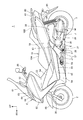
図1は、本発明の実施の形態に係る自動二輪車の左側面図である。
自動二輪車1(鞍乗り型車両)は、シート10に着座した乗員が足を載せる低床のステップフロア68を有するスクータ型車両であり、車体フレームF(図2)の前方に前輪2を有し、駆動輪である後輪3は、車両後部に配置されるユニットスイングエンジンU(ユニットスイングパワーユニット)に軸支されている。車体フレームFは、樹脂製の車体カバーCによって覆われている。
FIG. 1 is a left side view of a motorcycle according to an embodiment of the present invention.
The motorcycle 1 (saddle-ride type vehicle) is a scooter type vehicle having a low
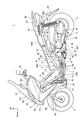
図2は、自動二輪車1の内部構造を示す左側面図であり、図3は、自動二輪車1の内部構造を示す右側面図である。図4は、車体フレームFの斜視図である。ここで、図2及び図3では、車体カバーCの一部が取り外された状態が示されている。
図2〜図4に示すように、車体フレームFは、金属製のチューブやパイプを溶接によって複数連結して形成されており、メインフレーム11は、前部に設けられるヘッドパイプ12と、ヘッドパイプ12から後下方に延出した後、略水平に後方へ延び、後部で後上方に延びる左右一対のダウンチューブ13,13と、ダウンチューブ13,13の下部から後上方へ車両後部まで延出する左右一対のシートレール14,14と、ヘッドパイプ12からダウンチューブ13,13の上方を後下方に延びてシートレール14,14に連結される左右一対のアッパーチューブ15,15とを有している。
ダウンチューブ13,13は、ヘッドパイプ12に前端が連結されて後下方へ延出する下方延出部70と、下方延出部70の下端から後方に略水平に延出する水平延出部71と、水平延出部71の後端から後上方に延出する斜め上方延出部72とを有している。
FIG. 2 is a left side view showing the internal structure of the
As shown in FIGS. 2 to 4, the vehicle body frame F is formed by connecting a plurality of metal tubes and pipes by welding, and the
The down
図4に示すように、メインフレーム11には、左右のフレームを連結するクロスメンバとして、ダウンチューブ13,13の下方延出部70,70の上部間を連結する前上部クロスメンバ16と、下方延出部70,70の下部間を連結する前クロスメンバ17と、ダウンチューブ13,13の水平延出部71,71間を連結する水平部クロスメンバ18と、アッパーチューブ15,15間を連結する上部クロスメンバ19と、シートレール14,14間を連結する中間クロスメンバ20と、シートレール14,14の後部間を連結する後部クロスメンバ21とを有している。水平部クロスメンバ18は、水平延出部71,71にボルト止めによって連結されている。
ダウンチューブ13,13の斜め上方延出部72,72の上部には、車幅方向外側に延出する左右一対のタンデムステップステー22,22が設けられている。
ヘッドパイプ12の前面には、灯火類や車体カバーC等を支持する籠状の前部フレーム24が連結されている。
また、メインフレーム11の外側方には、ダウンチューブ13,13に連結されて前後に延び、ステップフロア68を下方から支持する左右一対のステップフレーム23L,23R(図2、図3)が設けられている。
As shown in FIG. 4, the
A pair of left and right tandem step stays 22 and 22 extending outward in the vehicle width direction are provided on the upper portions of the obliquely upward extending
The front surface of the
A pair of left and right step frames 23L and 23R (FIGS. 2 and 3) that are connected to the
図1〜図3に示すように、前輪2を操向する操舵系は、ヘッドパイプ12に回動自在に軸支されるステアリングシャフト(不図示)と、このステアリングシャフトの上部に連結されるハンドル25とを有している。上記ステアリングシャフトの下端は、左右一対のフロントフォーク26,26に連結されており、前輪2は、フロントフォーク26,26の下端に軸支され、ハンドル25による操作によって操向される。
As shown in FIGS. 1 to 3, the steering system that steers the
ユニットスイングエンジンUは、エンジンEと、ベルト式の無段変速機構(不図示)が収容された伝動ケースMとが一体化されたユニットスイング式であり、後輪3を支持するスイングアームとしての機能も有している。ユニットスイングエンジンUは、その前部に連結されるリンク部材27を介して、ダウンチューブ13,13の後部に連結されており、リンク部材27に設けられるピボット軸28を中心にして上下に揺動自在である。
エンジンEは、水冷式の4サイクル単気筒エンジンであり、シリンダ軸線29が略水平に前方へ延びるように配置されている。エンジンEは、ユニットスイングエンジンUの前部に配置されるクランクケース30の前面に、シリンダ31及びシリンダヘッド32を結合して構成されている。
The unit swing engine U is a unit swing type in which an engine E and a transmission case M in which a belt-type continuously variable transmission mechanism (not shown) is accommodated, and is used as a swing arm that supports the rear wheel 3. It also has a function. The unit swing engine U is connected to the rear part of the
The engine E is a water-cooled four-cycle single-cylinder engine, and is arranged so that the
伝動ケースMは、クランクケース30の後部から後輪3の左側方を通って後方に延びている。クランクケース30の後部には、後輪3の右側方を通って後方に延びるアーム部33(図3)が設けられており、後輪3は、伝動ケースMの後部とアーム部33の後部との間に設けられる車軸3Aに支持されている。エンジンEの出力は、上記無段変速機構を介して後輪3に伝達される。
伝動ケースMの後端及びアーム部33の後端とシートレール14,14との間には、左右一対のリヤサスペンション34,34が掛け渡されている。
The transmission case M extends rearward from the rear portion of the
A pair of left and right
伝動ケースMの上面には、外気を吸い込むエアクリーナボックス35が設けられている。エアクリーナボックス35は、シリンダヘッド32の上面の吸気ポートに接続されたスロットルボディ36に、不図示のコネクティングチューブを介して接続されている。
シリンダヘッド32の下面の排気ポートに接続された排気管37は、エンジンEの下方を通って後方に延び、アーム部33の外側面に固定されたマフラー38に接続される。
伝動ケースMの後部の下部には、車両を直立状態に支持可能なメインスタンド39が設けられている。
On the upper surface of the transmission case M, an air
An
A
エンジンE用の燃料を貯留する燃料タンク40は、側面視において、前面がダウンチューブ13の下方延出部70に沿うとともに、後面がアッパーチューブ15に沿うように形成されており、上下方向では、ヘッドパイプ12の下部の後方からダウンチューブ13の水平延出部71近傍まで上下に長く延在している。燃料タンク40は、左右のダウンチューブ13,13の間に前傾して配置されている。
前傾した燃料タンク40の前部の下方の空間には、エンジンEの冷却水を冷却する板状のラジエータ41が設けられている。ラジエータ41とエンジンEとを接続する一対の冷却水パイプ42は、ラジエータ41の左側部から延出され、車両の左側(一側)のステップフレーム23L(図2)の下方を後方へ延び、ダウンチューブ13の内側を通ってエンジンEに接続される。
左側の水平延出部71には、サイドスタンド47が取り付けられている。
The
A plate-
A side stand 47 is attached to the left
ラジエータ41の冷却水の一部を貯留するリザーバタンク46は、ラジエータ41の後方において、車両の右側(他側)のステップフレーム23R(図3)の下方に配置されている。また、燃料タンク40の蒸発燃料を吸着するキャニスター43は、リザーバタンク46の後方においてステップフレーム23Rの下方に設けられている。
A
物品が収納される収納ボックス44は、シートレール14,14間に配置されており、燃料タンク40の後部の近傍から伝動ケースMの上方まで、シートレール14,14に沿って後上がりに延在している。収納ボックス44は、燃料タンク40とダウンチューブ13の斜め上方延出部72との間に配置される前部収納部44Aと、ユニットスイングエンジンUの上方に配置される後部収納部44Bとが、樹脂成形によって一体に形成されている。
収納ボックス44の上面は、その全長に亘って開口しており、この開口は、乗員用のシート10(図1)によって開閉自在に塞がれている。シート10は、運転者が着座する前部シート10Aと、前部シート10Aよりも一段高く形成されて同乗者が着座する後部シート10Bとを有している。
収納ボックス44の後方においてシートレール14,14の後部には、グラブレール48が固定されている。
A
The upper surface of the
A
図1に示すように、車体カバーCは、ヘッドパイプ12の前方及び左右側方を覆うとともに、下方延出部70の前方を下方に延びるフロントカバー50と、フロントカバー50の下部に連結され、前輪2の後方に位置するフロントロアカバー51(図2、図3)と、ハンドル25の下方でフロントカバー50の上部に連結される上部カバー52と、フロントカバー50の左右の縁部に連結されてヘッドパイプ12、アッパーチューブ15,15及び下方延出部70を後方及び側方から覆う上部インナーカバー53と、上部インナーカバー53の下縁に連結され、アッパーチューブ15,15及び下方延出部70を覆う左右一対の下部インナーカバー54,54と、フロントカバー50の下部及び下部インナーカバー54,54の下縁に連結され、ステップフレーム23L,23Rを上方から覆う左右一対のステップカバー55,55(図2、図3)と、フロントカバー50の下部及びステップカバー55,55の下部に連結されてステップフレーム23L,23Rを側方から覆う左右一対の前部フロアスカート56,56と、前部フロアスカート56,56に連続して後方へ延び、ダウンチューブ13,13を覆う左右一対の後部フロアスカート57,57と、左右の水平延出部71,71を下方から覆うアンダーカバー58と、下部インナーカバー54,54及びステップカバー55,55の後部に連結され、シート10の下方で収納ボックス44及びシートレール14,14を側方から覆う左右一対のボディサイドカバー59,59と、ボディサイドカバー59,59の後部に連結されるテールカバー60とを有している。
左右のステップカバー55,55の底部には、前部シート10Aに着座した運転者が足を載せるステップフロア68がそれぞれ形成されている。
As shown in FIG. 1, the vehicle body cover C is connected to the
On the bottoms of the left and right step covers 55, 55,
フロントカバー50の前部には、後上方に延びるウインドスクリーン61が設けられている。フロントカバー50の前端には、ヘッドライト62が設けられ、左右一対のウインカー63は、ヘッドライト62の上部に連続して設けられている。ヘッドライト62とウインドスクリーン61との間には、板状のガーニッシュ64が設けられている。
フロントフォーク26,26には、前輪2を上方から覆うフロントフェンダー65が設けられている。ボディサイドカバー59,59の下方には、後輪3を上方から覆うリヤフェンダー66が設けられている。
後部シート10Bの同乗者が足を載せる可倒式の一対のタンデムステップ67(図1)は、タンデムステップステー22,22に支持されている。
A
The
A pair of retractable tandem steps 67 (FIG. 1) on which the passengers of the
以下、自動二輪車1のフレーム構造について詳述する。
図5は、車体フレームFの左側面図である。図6は、車体フレームFを上方から見た平面図である。図7は、車体フレームFを後方から見た図である。
図4〜図7に示すように、各ダウンチューブ13,13は、ヘッドパイプ12の下部に前端が連結される下方延出部70と、下方延出部70の下端で後方に屈曲する第1屈曲部73と、第1屈曲部73から後方に延出する水平延出部71と、水平延出部71の後端に形成されて後上方に屈曲する第2屈曲部74と、第2屈曲部74から後上方に延出して後端がシートレール14,14に連結される斜め上方延出部72とを有し、一本の連続した金属チューブを、ベンダーによって第1屈曲部73及び第2屈曲部74で屈曲させて形成されている。左右のダウンチューブ13,13間の間隔は、後方側ほど大きくなっている。
Hereinafter, the frame structure of the
FIG. 5 is a left side view of the vehicle body frame F. FIG. FIG. 6 is a plan view of the vehicle body frame F as viewed from above. FIG. 7 is a view of the vehicle body frame F as seen from the rear.
As shown in FIGS. 4 to 7, each of the
リンク部材27を介してユニットスイングエンジンUを支持する左右一対のパワーユニット支持部85,85は、第2屈曲部74の後方に形成されている。
サイドスタンド47が取り付けられるスタンドステー47Aは、左側の水平延出部71において水平部クロスメンバ18の側方に設けられている。
A pair of left and right power
The stand stay 47 </ b> A to which the side stand 47 is attached is provided on the side of the
シートレール14,14は、前端がダウンチューブ13,13の下方延出部70の下部の後面に連結されて後上方に延び、後端が斜め上方延出部72の後端と連結されるシートレール前部75と、シートレール前部75の後端から車両の後部まで延びるシートレール後部76とを有している。左右のシートレール14,14間の間隔は、後方側ほど大きくなっている。
シートレール後部76の後部クロスメンバ21の前方には、シートレール14,14間を連結する後部第2クロスメンバ77が設けられ、後部第2クロスメンバ77と後部クロスメンバ21とは、前後に延びる補強板78によって連結されている。また、各シートレール後部76の上面には、グラブレール48が連結されるクラブレールステー79が設けられ、各シートレール後部76の前部には、収納ボックス44が連結されるボックスステー80が設けられている。
The seat rails 14, 14 are seats whose front ends are connected to the rear surface of the lower part of the downwardly extending
A rear
シートレール前部75,75は、後部のシートレール屈曲部75Aによって屈曲されており、シートレール14,14においてシートレール屈曲部75Aよりも後方の部分は、前部よりも後上がりの角度が緩くなっている。
板状の中間クロスメンバ20は、シートレール前部75,75の後部間に設けられており、シートレール14,14と各斜め上方延出部72の後端とが連結される後部連結部81よりも前方に位置している。シートレール前部75の前端と下方延出部70とが連結される前部連結部82は、下方延出部70の下端に設けられている。前クロスメンバ17は、前方に突出するU字状に形成されており、左右の前部連結部82,82の前面に連結されている。また、各前部連結部82の後方には、前部連結部82に近接した位置でシートレール前部75と水平延出部71とを連結する板状クロスメンバ83が設けられている。板状クロスメンバ83は、上下に延びる平板である。
The seat
The plate-shaped
アッパーチューブ15,15は、ヘッドパイプ12の上部に前端が連結され、下方延出部70よりも緩い傾斜で後下方に延び、後端が各シートレール前部75の上面に連結されている。アッパーチューブ15,15の下端が各シートレール前部75に連結されるアッパーチューブ連結部84は、板状クロスメンバ83よりも後方に位置している。左右のアッパーチューブ15,15間の間隔は、後方側ほど大きくなっている。また、アッパーチューブ15,15は、上面視において、その全長に亘り、ダウンチューブ13,13の内側に位置している。
The
図8は、パワーユニット支持部85を後方から見た斜視図である。
図4〜図8に示すように、パワーユニット支持部85,85は、左右のダウンチューブ13,13の第2屈曲部74及び斜め上方延出部72の下部にかけて設けられている。リンク部材27は、リンク部材27の前端を支持する前端連結部材86、及び、リンク部材27の後端を支持する連結ロッド87によってパワーユニット支持部85,85に連結される。
FIG. 8 is a perspective view of the
As shown in FIGS. 4 to 8, the power
パワーユニット支持部85,85は、金属板を箱状に形成した部材を第2屈曲部74及び斜め上方延出部72の後面に連結して形成されており、内部は中空である。左側のパワーユニット支持部85は、さらに後方及び上方に延びる連結ロッド支持部88を有している。連結ロッド支持部88は、互いに離間して配置される一対の板材88A,88Aをパワーユニット支持部85及び斜め上方延出部72の後面に連結して構成されており、連結ロッド87は、板材88A,88A間に支持される。板材88A,88Aは、後部に設けられる連結板88Bによって連結されて補強されている。
The power
前端連結部材86は、パワーユニット支持部85,85間に掛け渡されるパイプ90と、パイプ90の両端から車両下方に突出する一対のステー板91,91と、一方のパワーユニット支持部85に外側から挿通され、パイプ90及び他方のパワーユニット支持部85を貫通してナット92Aにより締結される支持ボルト92とを有している。ステー板91,91の先端には、ボルト孔(不図示)が設けられ、このボルト孔には、リンク部材27を前端連結部材86に連結する一本のボルト93が挿通される。
The front
リンク部材27は、前後に延びる一対のアーム部94,94と、アーム部94,94をその前端で連結するクロス部95とを有している。リンク部材27は、クロス部95がステー板91,91間に配置され、ステー板91,91及びクロス部95に挿通されるボルト93によって軸支される。ボルト93が挿通されるクロス部95の孔内には、ボルト93の外周に当接するゴムブッシュ(不図示)が設けられており、リンク部材27は前端連結部材86に弾性支持されている。
アーム部94,94の後端間には、ピボット軸28が掛け渡されている。ユニットスイングエンジンUは、クランクケース30の下部に形成された支持孔部30A(懸架ボス)(図2)がアーム部94,94の後端間に配置され、支持孔部30Aにピボット軸28が挿通されることで軸支される。すなわち、ユニットスイングエンジンUの揺動中心は、ピボット軸28であり、リンク部材27の後部に設けられている。
The
A
連結ロッド87は、左側のパワーユニット支持部85の連結ロッド支持部88に締結される2本の固定ボルト96,96によって、左側のパワーユニット支持部85に固定される。連結ロッド87は、上下方向に延びて配置されるロッドであり、固定ボルト96,96が挿通される固定孔部97,97を上部及び中間部に有し、ピボット軸28を軸支するピボット連結部98を下部に有している。ピボット連結部98は、ピボット軸28が左側のアーム部94の外側に突出したピボット突出部28Aに、ピボット突出部28Aに対して相対回転可能に連結されている。
The connecting
連結ロッド87の固定孔部97,97の内周面には、固定ボルト96,96の外周面に当接するゴムブッシュ99,99が設けられており、連結ロッド87は、連結ロッド支持部88に弾性支持されている。このため、連結ロッド87は、ゴムブッシュ99,99が撓む分だけ上下方向及び前後方向に移動可能であり、連結ロッド87に連結されたリンク部材27も連結ロッド87の移動に対応する分だけ移動する。
すなわち、ユニットスイングエンジンUを支持するリンク部材27は、クロス部95の上記ゴムブッシュ(不図示)及びゴムブッシュ99,99を介してパワーユニット支持部85,85に弾性支持されることで、上下方向及び前後方向に移動可能となっており、後輪3からユニットスイングエンジンUに入力される荷重は、ピボット軸28を介してリンク部材27に伝わり、上記荷重の一部は、リンク部材27が移動することで吸収される。このため、自動二輪車1の乗り心地が向上する。
That is, the
図4に示すように、車体フレームFには、シートレール前部75と、ダウンチューブ13,13の第1屈曲部73、水平延出部71、第2屈曲部74、及び、斜め上方延出部72とで形成された枠状フレーム部100が形成されている。パワーユニット支持部85,85は、枠状フレーム部100に形成されている。本実施の形態では、枠状フレーム部100が、車体フレームFの他の部分よりも優先的に捩れることで、ユニットスイングエンジンUからリンク部材27及びパワーユニット支持部85,85を経て車体フレームFに入力される荷重を吸収できるように構成されており、乗り心地の向上が図られている。
As shown in FIG. 4, the vehicle body frame F includes a seat
枠状フレーム部100は、シートレール前部75の前端が第1屈曲部73の上部に連結されるとともに、斜め上方延出部72が後上がりに延びてパワーユニット支持部85,85よりも後方の後部連結部81でシートレール前部75の後端に連結されるため、比較的大きな枠状に形成されている。これにより、枠状フレーム部100は適度に捩れることができ、ユニットスイングエンジンUから入力される荷重を枠状フレーム部100で吸収できる。
In the frame-
また、ダウンチューブ13,13は、一本の連続した金属チューブを、ベンダーによって第1屈曲部73及び第2屈曲部74で屈曲させて形成されたものであり、下方延出部70、第1屈曲部73、水平延出部71、第2屈曲部74及び斜め上方延出部72が一体に形成されているため、複数のチューブを溶接等によって連結した構成に比して、枠状フレーム部100に局所的に応力集中が生じたり、剛性の偏りが生じたりすることを抑制できる。このため、枠状フレーム部100をバランス良く捩らせることができ、ユニットスイングエンジンUから入力される荷重を枠状フレーム部100で効果的に吸収できる。
また、パワーユニット支持部85,85は、枠状フレーム部100の前後の中央部に設けられているため、ユニットスイングエンジンUからの荷重を枠状フレーム部100の全体で均一に受けることができ、効果的に荷重を吸収できる。さらに、パワーユニット支持部85,85が設けられた枠状フレーム部100が優先的に捩れることで、アッパーチューブ15,15、下方延出部70及びヘッドパイプ12側に大きな荷重が伝わることを抑制でき、ユニットスイングエンジンUからの荷重が操舵系に与える影響を低減できる。
The down
Moreover, since the power
また、前クロスメンバ17は、下方延出部70の下方の前部連結部82,82に連結されて枠状フレーム部100の前端部に設けられているため、枠状フレーム部100の撓み性(捩れ性)を確保しながら、ダウンチューブ13,13の剛性を高めることができる。このため、下方延出部70を介してヘッドパイプ12側の操舵系に荷重が伝わることを抑制でき、ユニットスイングエンジンUからの荷重が操舵系に与える影響を低減できる。
また、シートレール前部75の後部連結部81,81の前方の中間クロスメンバ20は、枠状フレーム部100の後端部に設けられているため、水平延出部71及び斜め上方延出部72の撓み性を確保しながら、シートレール14,14の剛性を高めることができる。このため、シートレール14,14を介して操舵系に荷重が伝わることを抑制でき、ユニットスイングエンジンUからの荷重が操舵系に与える影響を低減できる。
Further, since the
Further, since the
さらに、上下に延びる板状クロスメンバ83によって前部連結部82の近傍でシートレール14,14と各水平延出部71とを連結するため、シートレール14,14と各水平延出部71との連結強度を確保しつつ、枠状フレーム部100を適度に捩じらせることができる。板状クロスメンバ83は、パイプ状のクロスメンバに比して剛性が低いため、連結強度を確保しつつ、枠状フレーム部100の撓み性を確保できる。
また、枠状フレーム部100内には、剛性が高いパイプ状のクロスメンバは設けられていない。このため、枠状フレーム部100を適度に捩じらせることができ、ユニットスイングエンジンUからの荷重を枠状フレーム部100で効果的に吸収できる。
Furthermore, in order to connect the seat rails 14 and 14 and the horizontal extending
Further, a pipe-shaped cross member having high rigidity is not provided in the frame-shaped
以上説明したように、本発明を適用した実施の形態によれば、ダウンチューブ13,13は、ヘッドパイプ12に前端が連結されて後下方へ延出する下方延出部70、下方延出部70の下端で後方に屈曲する第1屈曲部73、第1屈曲部73から後方に略水平に延出する水平延出部71、水平延出部71の後端に形成される第2屈曲部74、及び、第2屈曲部74の後方で、後上方に延出する斜め上方延出部72を有し、斜め上方延出部72の後端がシートレール14,14に連結され、シートレール14,14は、ダウンチューブ13,13の下方延出部70にその前端が連結され、ユニットスイングエンジンUを支持するパワーユニット支持部85,85が、第2屈曲部74の後方に形成され、パワーユニット支持部85,85は、シートレール14,14及びダウンチューブ13,13で構成される大きな枠状の枠状フレーム部100,100の後方の外側に配置されることになるため、ユニットスイングエンジンU側から入力された荷重を、枠状フレーム部100,100が捩れることを利用して車体フレームF側で効果的に吸収することができる。また、フレームの要素を追加して車体フレームFの剛性を上げることで荷重を受ける手法ではなく、車体フレームFが捩れるように車体フレームFの剛性バランスを改善することで荷重を効果的に吸収するため、車体フレームFの軽量化を図ることができる。
As described above, according to the embodiment to which the present invention is applied, the
また、各ダウンチューブ13,13は、下方延出部70、水平延出部71、及び、斜め上方延出部72を有する一本の連続したチューブであるため、ダウンチューブ13,13の全体に亘って局所的な応力集中や剛性の偏りを抑制でき、ダウンチューブ13,13をバランス良く捩じらせることができる。このため、ユニットスイングエンジンU側から入力された荷重を、枠状フレーム部100,100で効果的に吸収できる。
また、各斜め上方延出部72とシートレール14,14との連結部である後部連結部81,81は、パワーユニット支持部85,85の後方に形成されるため、シートレール14,14の前端とダウンチューブ13,13の各下方延出部70との連結部である前部連結部82,82と、後部連結部81,81との間隔を大きくすることができ、枠状フレーム部100,100を適度に捩じらせることができる。
Moreover, since each down
Further, since the
さらに、パワーユニット支持部85,85とユニットスイングエンジンUのクランクケース30の下部に形成される支持孔部30Aとの間はリンク部材27を介して連結され、リンク部材27は、連結ロッド87を介して車体フレームFに対して相対移動可能に設けられるとともに、リンク部材27と支持孔部30Aとの連結部にユニットスイングエンジンUの揺動中心となるピボット軸28を有し、連結ロッド87の車体フレームF側の固定部となる連結ロッド支持部88は、左側のパワーユニット支持部85に形成されるため、ユニットスイングエンジンUからの入力荷重は、リンク部材27を介してパワーユニット支持部85,85に集約される。これにより、パワーユニット支持部85,85に集約された荷重で枠状フレーム部100,100を捩じらせることができ、枠状フレーム部100,100を適度に捩じらせることができるため、ユニットスイングエンジンUからの荷重を枠状フレーム部100,100で効果的に吸収できる。
Further, the power
また、ダウンチューブ13,13とシートレール14,14の前端との連結部である前部連結部82,82を、左右で連結する前クロスメンバ17が設けられ、シートレール14,14の前端側でヘッドパイプ12に近い部分の剛性が高まるため、ユニットスイングエンジンUからの荷重をヘッドパイプ12側の操舵系に伝達し難くすることができる。
Further, a
また、前部連結部82,82に隣接して、前部連結部82,82の後方に、ダウンチューブ13,13とシートレール14,14とを連結する板状クロスメンバ83,83が設けられるため、ダウンチューブ13,13の各水平延出部71及び各斜め上方延出部72の撓み性を確保しながら、ダウンチューブ13,13とシートレール14,14との連結強度を確保できる。
また、各斜め上方延出部72とシートレール14,14との連結部である後部連結部81,81の前方で、左右のシートレール14,14を連結する中間クロスメンバ20が設けられるため、ダウンチューブ13,13の各水平延出部71及び各斜め上方延出部72の撓み性を確保しながら、シートレール前部75,75の剛性を高めることができ、ユニットスイングエンジンUからの荷重をヘッドパイプ12側の操舵系に伝達し難くすることができる。
Further, plate-
In addition, since the
なお、上記実施の形態は本発明を適用した一態様を示すものであって、本発明は上記実施の形態に限定されるものではない。
上記の実施の形態では、ユニットスイングパワーユニットとして、ユニットスイングエンジンUを例に挙げて説明したが、本発明はこれに限定されるものではなく、ユニットスイングパワーユニットは、例えば、後輪3を駆動するモーターを、ピボット軸28に揺動自在に支持されてスイングアームを兼ねるケースに内蔵した電動の鞍乗り型車両のユニットスイング式のパワーユニットであっても良い。
In addition, the said embodiment shows the one aspect | mode which applied this invention, Comprising: This invention is not limited to the said embodiment.
In the above embodiment, the unit swing engine U is described as an example of the unit swing power unit. However, the present invention is not limited to this, and the unit swing power unit drives the rear wheel 3, for example. The motor may be a unit swing type power unit of an electric saddle riding type vehicle that is swingably supported by the
1 自動二輪車(鞍乗り型車両)
12 ヘッドパイプ
13,13 ダウンチューブ
14,14シートレール
15,15アッパーチューブ
17 前クロスメンバ
20 中間クロスメンバ
27 リンク部材
30A 支持孔部(懸架ボス)
70 下方延出部
71 水平延出部
72 斜め上方延出部
73 第1屈曲部
74 第2屈曲部
81 後部連結部(斜め上方延出部とシートレールとの連結部)
82 前部連結部(ダウンチューブとシートレールの前端との連結部)
83,83 板状クロスメンバ
85,85 パワーユニット支持部
87 連結ロッド
F 車体フレーム
U ユニットスイングエンジン(ユニットスイングパワーユニット)
1 Motorcycle (saddle-ride type vehicle)
12
70
82 Front connection (connection between the down tube and the front end of the seat rail)
83, 83 Plate-shaped
Claims (7)
前記シートレール(14,14)は、前記ダウンチューブ(13,13)の前記下方延出部(70)にその前端が連結され、
前記ダウンチューブ(13,13)は、前記水平延出部(71)の後端に形成される第2屈曲部(74)と、当該第2屈曲部(74)の後方で、後上方に延出する斜め上方延出部(72)とを有するとともに、当該斜め上方延出部(72)の後端が前記シートレール(14,14)に連結され、
前記ユニットスイングパワーユニット(U)を支持するパワーユニット支持部(85,85)が、前記第2屈曲部(74)の後方に形成されることを特徴とする鞍乗り型車両のフレーム構造。 A head pipe (12) that rotatably supports the steering system, and a pair of left and right, a lower extension portion (70) that is connected to the head pipe (12) and that extends rearward and downward, the lower portion A down having a first bent portion (73) bent backward at the lower end of the extended portion (70), and a horizontal extended portion (71) extended substantially horizontally rearward from the first bent portion (73). It consists of a tube (13, 13) and a pair of left and right, is disposed above the down tube (13, 13), and has a front end connected to the down tube (13, 13) and extends rearward and upward. A pair of left and right seat rails (14, 14) is configured, and a front end is connected to the head pipe (12), and is disposed above the down tube (13, 13), and the seat rails (14, 14). ) In the middle part A vehicle body frame (F) having an upper tube (15, 15) to which ends are connected, and a unit swing power unit that is swingably supported by the vehicle body frame (F) and has a rocking center on the lower side. (U) in the frame structure of a saddle-ride type vehicle,
The front end of the seat rail (14, 14) is connected to the downward extension (70) of the down tube (13, 13),
The down tube (13, 13) includes a second bent portion (74) formed at the rear end of the horizontal extending portion (71) and a rear upper portion behind the second bent portion (74). And a rear end of the diagonally upward extending portion (72) is connected to the seat rail (14, 14),
A frame structure for a saddle-ride type vehicle, wherein power unit support portions (85, 85) for supporting the unit swing power unit (U) are formed behind the second bent portion (74).
前記リンク部材(27)は、前記車体フレーム(F)に連結される連結ロッド(87)を介して前記車体フレーム(F)に対して相対移動可能に設けられるとともに、当該リンク部材(27)と前記懸架ボス(30A)との連結部に前記ユニットスイングパワーユニット(U)の揺動中心を有し、
前記連結ロッド(87)の前記車体フレーム(F)側の固定部は、前記パワーユニット支持部(85)に形成されることを特徴とする請求項1から3のいずれかに記載の鞍乗り型車両のフレーム構造。 The power unit support (85, 85) provided on the vehicle body frame (F) and the suspension boss (30A) formed on the unit swing power unit (U) side are connected via a link member (27). And
The link member (27) is provided to be movable relative to the vehicle body frame (F) via a connecting rod (87) connected to the vehicle body frame (F). Having a swing center of the unit swing power unit (U) at the connecting portion with the suspension boss (30A);
The saddle riding type vehicle according to any one of claims 1 to 3, wherein a fixing portion of the connecting rod (87) on the vehicle body frame (F) side is formed on the power unit support portion (85). Frame structure.
Priority Applications (4)
| Application Number | Priority Date | Filing Date | Title |
|---|---|---|---|
| JP2012065153A JP6001892B2 (en) | 2012-03-22 | 2012-03-22 | Frame structure of saddle-ride type vehicle |
| IT000132A ITTO20130132A1 (en) | 2012-03-22 | 2013-02-18 | FRAME STRUCTURE FOR A SADDLE-TYPE VEHICLE. |
| ES201330254A ES2460340B2 (en) | 2012-03-22 | 2013-02-25 | FRAME FOR MOTORCYCLE TYPE VEHICLE |
| US13/798,877 US8757312B2 (en) | 2012-03-22 | 2013-03-13 | Frame structure for saddle-ride type vehicle |
Applications Claiming Priority (1)
| Application Number | Priority Date | Filing Date | Title |
|---|---|---|---|
| JP2012065153A JP6001892B2 (en) | 2012-03-22 | 2012-03-22 | Frame structure of saddle-ride type vehicle |
Publications (2)
| Publication Number | Publication Date |
|---|---|
| JP2013193647A true JP2013193647A (en) | 2013-09-30 |
| JP6001892B2 JP6001892B2 (en) | 2016-10-05 |
Family
ID=49211074
Family Applications (1)
| Application Number | Title | Priority Date | Filing Date |
|---|---|---|---|
| JP2012065153A Expired - Fee Related JP6001892B2 (en) | 2012-03-22 | 2012-03-22 | Frame structure of saddle-ride type vehicle |
Country Status (4)
| Country | Link |
|---|---|
| US (1) | US8757312B2 (en) |
| JP (1) | JP6001892B2 (en) |
| ES (1) | ES2460340B2 (en) |
| IT (1) | ITTO20130132A1 (en) |
Cited By (1)
| Publication number | Priority date | Publication date | Assignee | Title |
|---|---|---|---|---|
| WO2019181128A1 (en) * | 2018-03-23 | 2019-09-26 | 本田技研工業株式会社 | Pipe frame strengthening structure |
Families Citing this family (6)
| Publication number | Priority date | Publication date | Assignee | Title |
|---|---|---|---|---|
| JP5913030B2 (en) * | 2012-03-22 | 2016-04-27 | 本田技研工業株式会社 | Storage structure for saddle-ride type vehicles |
| US9394026B2 (en) * | 2013-07-01 | 2016-07-19 | 3G Bikes, Llc | Step-through bicycle frame |
| JP5951655B2 (en) * | 2014-01-10 | 2016-07-13 | 本田技研工業株式会社 | Storage structure for saddle-ride type vehicles |
| CN107651077B (en) * | 2017-09-22 | 2024-01-30 | 重庆隆鑫机车有限公司 | Motorcycle frame and motorcycle thereof |
| CN114641429A (en) * | 2019-11-13 | 2022-06-17 | 扎普电动车有限公司 | Seat supporting structure for mounting on electric motorcycle frame |
| JP2021133758A (en) * | 2020-02-26 | 2021-09-13 | ヤマハ発動機株式会社 | Saddle-riding type vehicle |
Citations (6)
| Publication number | Priority date | Publication date | Assignee | Title |
|---|---|---|---|---|
| JPH07285483A (en) * | 1994-04-21 | 1995-10-31 | Yamaha Motor Co Ltd | Body frame for motorcycle |
| JPH11198890A (en) * | 1998-01-13 | 1999-07-27 | Suzuki Motor Corp | Supporting structure of unit swing type motorcycle engine |
| JP2007055584A (en) * | 2005-07-25 | 2007-03-08 | Yamaha Motor Co Ltd | Motorcycle |
| JP2007062611A (en) * | 2005-08-31 | 2007-03-15 | Honda Motor Co Ltd | Motorcycle |
| JP2011073510A (en) * | 2009-09-29 | 2011-04-14 | Honda Motor Co Ltd | Motorcycle |
| WO2011099209A1 (en) * | 2010-02-09 | 2011-08-18 | スズキ株式会社 | Scooter-type two-wheeled motor vehicle |
Family Cites Families (4)
| Publication number | Priority date | Publication date | Assignee | Title |
|---|---|---|---|---|
| JP4537927B2 (en) * | 2005-09-30 | 2010-09-08 | 本田技研工業株式会社 | Power unit support structure for scooter type vehicles |
| ES2364368T3 (en) * | 2006-06-09 | 2011-09-01 | Yamaha Hatsudoki Kabushiki Kaisha | MOTORCYCLE. |
| US8177013B2 (en) * | 2009-05-28 | 2012-05-15 | Liang Chang | Motorcycle rear-wheels transmission and suspension system |
| JP5879878B2 (en) * | 2011-09-28 | 2016-03-08 | スズキ株式会社 | Motorcycle |
-
2012
- 2012-03-22 JP JP2012065153A patent/JP6001892B2/en not_active Expired - Fee Related
-
2013
- 2013-02-18 IT IT000132A patent/ITTO20130132A1/en unknown
- 2013-02-25 ES ES201330254A patent/ES2460340B2/en not_active Expired - Fee Related
- 2013-03-13 US US13/798,877 patent/US8757312B2/en not_active Expired - Fee Related
Patent Citations (6)
| Publication number | Priority date | Publication date | Assignee | Title |
|---|---|---|---|---|
| JPH07285483A (en) * | 1994-04-21 | 1995-10-31 | Yamaha Motor Co Ltd | Body frame for motorcycle |
| JPH11198890A (en) * | 1998-01-13 | 1999-07-27 | Suzuki Motor Corp | Supporting structure of unit swing type motorcycle engine |
| JP2007055584A (en) * | 2005-07-25 | 2007-03-08 | Yamaha Motor Co Ltd | Motorcycle |
| JP2007062611A (en) * | 2005-08-31 | 2007-03-15 | Honda Motor Co Ltd | Motorcycle |
| JP2011073510A (en) * | 2009-09-29 | 2011-04-14 | Honda Motor Co Ltd | Motorcycle |
| WO2011099209A1 (en) * | 2010-02-09 | 2011-08-18 | スズキ株式会社 | Scooter-type two-wheeled motor vehicle |
Cited By (2)
| Publication number | Priority date | Publication date | Assignee | Title |
|---|---|---|---|---|
| WO2019181128A1 (en) * | 2018-03-23 | 2019-09-26 | 本田技研工業株式会社 | Pipe frame strengthening structure |
| JPWO2019181128A1 (en) * | 2018-03-23 | 2021-03-11 | 本田技研工業株式会社 | Reinforced structure of pipe frame |
Also Published As
| Publication number | Publication date |
|---|---|
| ES2460340A2 (en) | 2014-05-13 |
| ITTO20130132A1 (en) | 2013-09-23 |
| ES2460340B2 (en) | 2015-05-12 |
| JP6001892B2 (en) | 2016-10-05 |
| ES2460340R1 (en) | 2014-10-06 |
| US20130249186A1 (en) | 2013-09-26 |
| US8757312B2 (en) | 2014-06-24 |
Similar Documents
| Publication | Publication Date | Title |
|---|---|---|
| JP6001892B2 (en) | Frame structure of saddle-ride type vehicle | |
| JP5373181B2 (en) | Motorcycle | |
| US10780937B2 (en) | Frame structure for a motorcycle | |
| JP5400723B2 (en) | Saddle riding | |
| JP4986603B2 (en) | Motorcycles and tricycles | |
| KR101254909B1 (en) | Saddle type vehicle | |
| JP6288524B2 (en) | Saddle riding | |
| US7407031B2 (en) | All terrain vehicle | |
| JP2012158270A (en) | Motorcycle frame | |
| EP1818249B1 (en) | Motorcycle comprising a rear cushion arrangement structure | |
| JP5151765B2 (en) | Body frame structure of motorcycle | |
| JP6770913B2 (en) | Swing arm structure of saddle-riding vehicle | |
| JP3548173B2 (en) | Frame structure for motorcycle | |
| JP5858808B2 (en) | Frame structure of saddle riding type vehicle | |
| JP6133662B2 (en) | Suspension structure of unit swing engine for saddle riding type vehicle | |
| US8746390B2 (en) | Body frame of straddle-type vehicle | |
| JP5442132B2 (en) | Motorcycle | |
| JP4727315B2 (en) | Motorcycle body structure | |
| JP6101663B2 (en) | Rear carrier for saddle-ride type vehicles | |
| CN102689666A (en) | Motorcycle | |
| JP6766111B2 (en) | Saddle-type vehicle | |
| JP5005647B2 (en) | Scooter type vehicle | |
| JP2006103349A (en) | Motorcycle | |
| WO2015079567A1 (en) | Vehicle body frame structure for saddle type vehicle | |
| JP5307497B2 (en) | Low floor saddle riding type vehicle |
Legal Events
| Date | Code | Title | Description |
|---|---|---|---|
| A621 | Written request for application examination |
Free format text: JAPANESE INTERMEDIATE CODE: A621 Effective date: 20141127 |
|
| A977 | Report on retrieval |
Free format text: JAPANESE INTERMEDIATE CODE: A971007 Effective date: 20150722 |
|
| A131 | Notification of reasons for refusal |
Free format text: JAPANESE INTERMEDIATE CODE: A131 Effective date: 20150804 |
|
| A521 | Request for written amendment filed |
Free format text: JAPANESE INTERMEDIATE CODE: A523 Effective date: 20151002 |
|
| A131 | Notification of reasons for refusal |
Free format text: JAPANESE INTERMEDIATE CODE: A131 Effective date: 20160329 |
|
| A521 | Request for written amendment filed |
Free format text: JAPANESE INTERMEDIATE CODE: A523 Effective date: 20160526 |
|
| TRDD | Decision of grant or rejection written | ||
| A01 | Written decision to grant a patent or to grant a registration (utility model) |
Free format text: JAPANESE INTERMEDIATE CODE: A01 Effective date: 20160830 |
|
| A61 | First payment of annual fees (during grant procedure) |
Free format text: JAPANESE INTERMEDIATE CODE: A61 Effective date: 20160902 |
|
| R150 | Certificate of patent or registration of utility model |
Ref document number: 6001892 Country of ref document: JP Free format text: JAPANESE INTERMEDIATE CODE: R150 |
|
| R250 | Receipt of annual fees |
Free format text: JAPANESE INTERMEDIATE CODE: R250 |
|
| LAPS | Cancellation because of no payment of annual fees |