JP2013190028A - Solenoid valve - Google Patents
Solenoid valve Download PDFInfo
- Publication number
- JP2013190028A JP2013190028A JP2012056636A JP2012056636A JP2013190028A JP 2013190028 A JP2013190028 A JP 2013190028A JP 2012056636 A JP2012056636 A JP 2012056636A JP 2012056636 A JP2012056636 A JP 2012056636A JP 2013190028 A JP2013190028 A JP 2013190028A
- Authority
- JP
- Japan
- Prior art keywords
- iron core
- solenoid valve
- guide
- circle
- press
- Prior art date
- Legal status (The legal status is an assumption and is not a legal conclusion. Google has not performed a legal analysis and makes no representation as to the accuracy of the status listed.)
- Granted
Links
Images
Abstract
Description
本発明は、自動変速機などの油圧制御装置における油圧回路中に使用するソレノイドバルブに関する。 The present invention relates to a solenoid valve used in a hydraulic circuit in a hydraulic control device such as an automatic transmission.
従来、この種のソレノイドバルブは、ボビン51と円筒キャップ型ターミナル54は、コイルのヒュージングや成型時の仮止めとしてボビンの爪部51aとターミナルのツバ部54aに設けられた係止穴との係止により係合されており、電源供給ターミナル53,ボビン51、円筒キャップ型ターミナル54及びコイル52は、樹脂インサート成形によりコネクタ部を有するケース59に固定されていた(例えば、特許文献1参照。) Conventionally, in this type of solenoid valve, the bobbin 51 and the cylindrical cap-type terminal 54 are provided with a claw portion 51a of the bobbin and a locking hole provided in the flange portion 54a of the terminal as a temporary stop at the time of coil fusing or molding. The power supply terminal 53, the bobbin 51, the cylindrical cap type terminal 54, and the coil 52 are fixed to a case 59 having a connector portion by resin insert molding (see, for example, Patent Document 1). )
特許文献1では、ボビンの爪部51aとターミナルのツバ部54bとのガタにより、円筒キャップ型ターミナル54の周方向位置決め精度が悪く、コイル52との接合工程で位置ズレの原因となる可能性がある。
本発明は上記の課題を解決するためになされたもので、円筒キャップ型ターミナルの圧入部の穴形状を従来円形に対し三角おにぎり形状とし、逃がしを省いても内径バラツキに対し圧入荷重変動を抑えた。これにより、圧入荷重を安定させ、且つ圧入時の変形を防止させることができ、コスト面でも安価に製造が可能にしたソレノイドバルブを提供することを目的とする。
In Patent Literature 1, the circumferential positioning accuracy of the cylindrical cap-type terminal 54 is poor due to the backlash between the bobbin claw portion 51 a and the terminal flange portion 54 b, which may cause positional displacement in the joining process with the coil 52. is there.
The present invention has been made to solve the above-mentioned problems. The hole shape of the press-fitted portion of the cylindrical cap type terminal is a triangular rice ball shape with respect to the conventional circular shape, and even if the relief is omitted, the fluctuation of the press-fit load is suppressed against the variation in the inner diameter. It was. Accordingly, an object of the present invention is to provide a solenoid valve that can stabilize a press-fitting load and prevent deformation at the time of press-fitting, and can be manufactured at low cost.
上記目的を達成するために、本発明のソレノイドバルブは、
固定鉄芯と、
前記固定鉄芯の回りに設けられたソレノイドコイルと、
前記固定鉄芯と前記ソレノイドコイルの吸引力により可動する可動鉄芯と、
前記可動鉄芯により流体の流れを制御するようにされた弁部と、を有し、
前記固定鉄芯は断面凹状の空間部を有する円筒部と、前記空間部の開口端に設けられた鍔部と、を有し、
前記可動鉄芯が前記底部に直接又は間接に離接するようにされたソレノイドバルブにおいて、
前記ソレノイドコイルの端部に固定され前記可動鉄芯を摺動可能となるように外周に嵌挿したガイドと、
前記ガイドの円筒部に嵌挿されたアース端子と、
を備え、
前記ガイドの円筒部の直径に対し前記アース端子の圧入部の穴形状が外接円と内接円との間に入るように、円周方向に少なくとも3等配毎に外接円に内接し、且つ内接円に外接する円弧で繋げ、繋ぎ目に丸み(R)を設けたことを特徴とする。
本発明のソレノイドバルブは、前記第1の特徴に加えて、前記ガイドの直径に対し前記アース端子のフランジ部外径が150〜160%の場合において前記アース端子の圧入部の穴形状が100〜105%の外接円と95〜99%の内接円との間に入るように、円周方向に3等配毎に外接円に内接し、且つ内接円に外接する円弧を繋げ、繋ぎ目に丸み(R)を設けたことを特徴とする。
また、本発明のソレノイドバルブは、前記第1又は第2の特徴に加えて、前記圧入部の穴形状は多角形または三角形おにぎり形状にしたことを特徴とする。
In order to achieve the above object, the solenoid valve of the present invention comprises:
A fixed iron core,
A solenoid coil provided around the fixed iron core;
A movable iron core movable by the suction force of the fixed iron core and the solenoid coil;
A valve portion adapted to control the flow of fluid by the movable iron core,
The fixed iron core has a cylindrical part having a space part having a concave cross section, and a flange part provided at an opening end of the space part,
In the solenoid valve in which the movable iron core is adapted to be in direct contact or indirect contact with the bottom portion,
A guide that is fixed to an end of the solenoid coil and is fitted on the outer periphery so that the movable iron core can slide;
A ground terminal fitted into the cylindrical portion of the guide;
With
Inscribed in the circumscribed circle at least every three equal intervals in the circumferential direction so that the hole shape of the press-fitted portion of the ground terminal is between the circumscribed circle and the inscribed circle with respect to the diameter of the cylindrical portion of the guide, and It is characterized in that it is connected by an arc circumscribing an inscribed circle and rounded (R) is provided at the joint.
In addition to the first feature, the solenoid valve of the present invention has a hole shape of the press-fit portion of the ground terminal of 100 to 160% when the outer diameter of the flange portion of the ground terminal is 150 to 160% with respect to the diameter of the guide. Connect the arcs that are inscribed in the circumscribed circle every three equal intervals in the circumferential direction so that they fall between the circumscribed circle of 105% and the inscribed circle of 95-99%. Is provided with a roundness (R).
In addition to the first or second feature, the solenoid valve of the present invention is characterized in that the hole shape of the press-fit portion is a polygonal or triangular rice ball shape.
本発明はガイドにアース端子を圧入する際、ガイドとの接触面積を減らし、多角形または三角形おにぎり形状を円形に変形させながら圧入することにより圧入荷重を低下・安定させると共に、アース端子の変形を抑えることができコスト面でも安価に製造することが可能になった。 The present invention reduces the contact area with the guide when the ground terminal is press-fitted into the guide, reduces and stabilizes the press-fitting load by deforming the polygonal or triangular onigiri shape into a circle, and reduces the deformation of the ground terminal. It is possible to suppress the manufacturing cost and the manufacturing cost can be reduced.
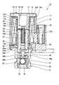
以下、本発明のソレノイドバルブにつき好適な実施の形態を挙げ、添付図面を参照して詳細に説明する。図1は本発明の実施の形態を示すソレノイドバルブ10の縦断面図である。
図1に示すように、固定鉄芯12は、断面凹状の空間部16を有する円筒部17と、空間部16の開口端18に設けられた鍔部19とを有している。空間部16の底部20にはドレーン穴用の貫通穴21が設けられている。
Preferred embodiments of the solenoid valve of the present invention will be described below in detail with reference to the accompanying drawings. FIG. 1 is a longitudinal sectional view of a
As shown in FIG. 1, the fixed
固定鉄芯12の円筒部17の外側17a及び鍔部19の円筒部外周面19aに近接するようにソレノイドコイル13が嵌挿されている。前記ソレノイドコイル13はプラスチック製のボビン13aに巻き線13bが巻かれている。前記ボビン13aの上端13cが鍔部19に対向して配置され、ボビン13aの内径13dが円筒部外周面17aに嵌挿されている。ボビン13aの下方の内径13dには円筒部25bを有し、下方に鍔部25aを有するガイド25が嵌挿されている。
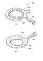
断面略L字形状のアース端子26は鍔部26aをボビン13aの下端13eに係合するとともに、該ボビン13aの下端13e及び鍔部25aの間に係合し、かつ圧入部26d(図2参照)がガイド25の円筒部25bに嵌挿してガイド25の鍔部25a上に固定されている。
The
The
図2はアース端子26の構造を示す概略図で、該アース端子26はフランジ上面26a及び下面26bと、該フランジ上面26a及び下面26bにより形成されるターミナル端子26cと、フランジ上面26a及び下面26bに形成された三角おにぎり形状の圧入部26dと、該圧入部26dの周囲にフランジ上面26aに突出し、外郭が三角おにぎり形状を有する凸部26eと、を備える。
なお、アース端子26は通常、プレス成形加工で行うので前記凸部26eの外周面(外郭)は三角おにぎり形状になるが、円筒形状にしてもよい。
FIG. 2 is a schematic view showing the structure of the
Since the
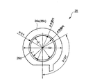
図3に示すようにアース端子26の三角おにぎり形状の圧入部26dの形状は、被圧入側の直径、例えばガイド25の円筒部25bの直径D1に対し三角おにぎり形状に形成されており、アース端子26のフランジ上面26a及び下面26bのフランジ部の直径D2が150〜160%の場合において、100〜105%の外接円と95〜99%の内接円との間に入るように、120°毎に外接円に内接し、且つ内接円に外接する円弧を繋げ、繋ぎ目に圧入部方向に丸み、例えば0.5R(図2(B)参照)を設けた形状に形成されている。
また、圧入部26dの形状は、三角おにぎり形状に限らず局部逃がし以外の2つの円、例えば内接円、外接円内に入る曲線で、楕円形状やひし形状の穴形状とし、圧入部の部分変形を導くことで圧入荷重を調整出来る構造にしてもよい。
As shown in FIG. 3, the shape of the triangular onigiri-shaped press-
Further, the shape of the press-
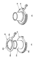
図4はガイド25とアース端子26との嵌挿手順及び嵌挿状態を示す説明図で、図4(A)はガイド25の円筒部25bの外周面の上部からアース端子26の圧入部26dを嵌挿する前段階を示し、図4(B)はガイド25の円筒部25bにアース端子26の圧入部26dに嵌挿・圧入してガイド25の鍔部25aにアース端子26のフランジ下面26bが係合されている。
本発明に係るソレノイドバルブは、図3に示すようにアース端子26をガイド25の円筒部25bに圧入する際、アース端子26の圧入部26dの穴形状を図4に示す寸法に保持することにより、ガイド25とアース端子26との接触面積を減らし、三角おにぎり形状を円形に変形させながら圧入することにより圧入荷重を低下・安定させると共に、アース端子26のターミナル端子26cの変形を抑える。
FIG. 4 is an explanatory view showing the insertion procedure and the insertion state of the
The solenoid valve according to the present invention maintains the hole shape of the press-
アース端子26の形状は、圧入部26dにおいて、三角おにぎり形状に限らず、局部逃がし以外の2つの円内に入る曲線で、楕円形やひし形の穴形状とし、圧入部の部分変形を導くことで圧入荷重を調整出来る構造も可能である。
さらに、アース端子26の材料は黄銅であるが、C1100やSPCCなど一般的に端子に使用される黄銅、銅、鉄を主成分とする材料であっても良い。
The shape of the
Further, although the material of the
固定鉄芯12の下端12a及びガイド25の円筒部25bの内径に沿って移動可能に可動鉄芯27が設けられている。前記固定鉄芯12と可動鉄芯27の間には非磁性体のシム28が設けられ、固定鉄芯12と移動鉄芯27とが直接接触しないようにされている。可動鉄芯27は中空円筒状であり、底部にピン29が固定されている。前記ピン29の上部には、内穴27aにばね部材30設けられ、該ばね部材30の上部が固定鉄芯12の下端12aにシム28を介して当接し、ばね部材30の弾発力により固定鉄芯12と可動鉄芯27が離隔するようにされている。
A
可動鉄芯27及びアース端子26の下部に弁部31が設けられている。前記弁部31は上部に鍔31aを有し、弁部31の鍔31a、アース端子26、ソレノイドコイル13、固定鉄芯12の鍔部19がカバー32の両端部32a,32bで挟持するように加締め固定されている。
図1は3方向2位置のノーマルクローズ弁であり、弁部31は下端に圧力ポート33が設けられ、上方に開口する圧力ポート側弁座34、該圧力ポート側弁座34に離着座するボール35が設けられている。ボール35の上側には下方に開口するタンクポート側弁座36が設けられ、ボール35が離着座可能に配置されている。圧力ポート側弁座34とタンクポート側弁座36間に連通して負荷ポート37が設けられ、図示しない負荷に接続されている。タンクポート側弁座36はピン貫通穴36aに連接し、タンク穴36bを経由してタンクポート38に連通し、ソレノイドバルブ10の外部に排出される。
A
FIG. 1 shows a normally closed valve in three directions and two positions. A
可動鉄芯27に装着されたピン29はその先端29aがばね部材30の弾発力によりボール35に当接可能にされており、ソレノイドコイル13に通電することにより固定鉄芯12側に吸引され、ボール35と接触しないようにされる。
図1に示すように、ソレノイドコイル13が非通電磁の場合は、ボール35はばね部材30の弾発力により、ピン29に押され圧力ポート側弁座34に着座し、圧力ポート33と負荷ポート37を遮断し、負荷ポート37とタンクポート38を連通させる。
A
As shown in FIG. 1, when the
一方、ソレノイドコイル13が通電され、ピン29がボール35と離れているときは、ボール35は圧力ポート33の圧力に押され、タンクポート側弁座36に着座し、圧力ポート33と負荷ポート37を連通し、負荷ポート37とタンクポート386を遮断させる。
これにより、ソレノイドコイル13のON−OFFにより流路を切り換える3方向2位置のノーマルクローズ弁を提供する。なお、固定鉄芯12の開口側がソレノイドバルブ1の外部に開放されており、また、ソレノイドバルブ1の内部リーク等はシム28のドレーン穴(図示せず)、固定鉄芯12の貫通穴21等を通ってドレーンとしてソレノイドバルブ外部に排出される。
On the other hand, when the
This provides a three-way two-position normal close valve that switches the flow path by turning the
なお、上述したソレノイドバルブ10はソレノイドコイル13に通電しない状態で圧力ポート33と負荷ポート37とを連通しないノーマルクローズ弁であるが、構造を逆転して通電しない状態で圧力ポートと負荷ポートとを連通するノーマルオープン弁であっても本発明には適用可能である。
The
10 ソレノイドバルブ 11 固定鉄芯
13 ソレノイドコイル 25 ガイド
26 アース端子 27 可動鉄芯
31 弁部 33 圧力ポート
37 負荷ポート
DESCRIPTION OF
Claims (3)
前記固定鉄芯の回りに設けられたソレノイドコイルと、
前記固定鉄芯と前記ソレノイドコイルの吸引力により可動する可動鉄芯と、
前記可動鉄芯により流体の流れを制御するようにされた弁部と、を有し、
前記固定鉄芯は断面凹状の空間部を有する円筒部と、前記空間部の開口端に設けられた鍔部と、を有し、
前記可動鉄芯が前記底部に直接又は間接に離接するようにされたソレノイドバルブにおいて、
前記ソレノイドコイルの端端に固定され前記可動鉄芯を摺動可能となるように外周に嵌挿したガイドと、
前記ガイドの円筒部に嵌挿されたアース端子と、
を備え、
前記ガイドの円筒部の直径に対し前記アース端子の圧入部の穴形状が外接円と内接円との間に入るように、円周方向に少なくとも3等配毎に外接円に内接し、且つ内接円に外接する円弧で繋げ、繋ぎ目に丸み(R)を設けたことを特徴とするソレノイドバルブ。 A fixed iron core,
A solenoid coil provided around the fixed iron core;
A movable iron core movable by the suction force of the fixed iron core and the solenoid coil;
A valve portion adapted to control the flow of fluid by the movable iron core,
The fixed iron core has a cylindrical part having a space part having a concave cross section, and a flange part provided at an opening end of the space part,
In the solenoid valve in which the movable iron core is adapted to be in direct contact or indirect contact with the bottom portion,
A guide that is fixed to the end of the solenoid coil and is fitted on the outer periphery so that the movable iron core can slide;
A ground terminal fitted into the cylindrical portion of the guide;
With
Inscribed in the circumscribed circle at least every three equal intervals in the circumferential direction so that the hole shape of the press-fitted portion of the ground terminal is between the circumscribed circle and the inscribed circle with respect to the diameter of the cylindrical portion of the guide, and A solenoid valve characterized in that it is connected by an arc circumscribing an inscribed circle and rounded (R) is provided at the joint.
前記圧入部の穴形状は多角形または三角形おにぎり形状にしたことを特徴とするソレノイドバルブ。 The solenoid valve according to claim 1 or 2,
The solenoid valve according to claim 1, wherein a hole shape of the press-fitting portion is a polygonal or triangular rice ball shape.
Priority Applications (1)
| Application Number | Priority Date | Filing Date | Title |
|---|---|---|---|
| JP2012056636A JP5994302B2 (en) | 2012-03-14 | 2012-03-14 | Manufacturing method of solenoid valve |
Applications Claiming Priority (1)
| Application Number | Priority Date | Filing Date | Title |
|---|---|---|---|
| JP2012056636A JP5994302B2 (en) | 2012-03-14 | 2012-03-14 | Manufacturing method of solenoid valve |
Publications (2)
| Publication Number | Publication Date |
|---|---|
| JP2013190028A true JP2013190028A (en) | 2013-09-26 |
| JP5994302B2 JP5994302B2 (en) | 2016-09-21 |
Family
ID=49390504
Family Applications (1)
| Application Number | Title | Priority Date | Filing Date |
|---|---|---|---|
| JP2012056636A Active JP5994302B2 (en) | 2012-03-14 | 2012-03-14 | Manufacturing method of solenoid valve |
Country Status (1)
| Country | Link |
|---|---|
| JP (1) | JP5994302B2 (en) |
Cited By (5)
| Publication number | Priority date | Publication date | Assignee | Title |
|---|---|---|---|---|
| CN103928208A (en) * | 2014-05-04 | 2014-07-16 | 任金瑞 | Movable iron core of automatic gearbox of electric automobile and electric tricycle |
| CN104565475A (en) * | 2013-10-15 | 2015-04-29 | 浙江盾安人工环境股份有限公司 | Electronic expansion valve |
| KR20200128348A (en) | 2018-03-16 | 2020-11-12 | 가부시키가이샤 아루박 | Slide valve |
| KR20200135136A (en) | 2018-03-30 | 2020-12-02 | 가부시키가이샤 아루박 | Gate valve |
| KR20200135135A (en) | 2018-04-02 | 2020-12-02 | 가부시키가이샤 아루박 | Gate valve |
Citations (4)
| Publication number | Priority date | Publication date | Assignee | Title |
|---|---|---|---|---|
| JPH0292173U (en) * | 1989-01-06 | 1990-07-23 | ||
| WO2000008340A1 (en) * | 1998-08-03 | 2000-02-17 | Snap-Tite Technologies, Inc. | Unitary coil and valve assembly |
| JP2003028339A (en) * | 2001-07-12 | 2003-01-29 | Nachi Fujikoshi Corp | Strainer for control valve |
| JP2005351330A (en) * | 2004-06-09 | 2005-12-22 | Denso Corp | Solenoid valve |
-
2012
- 2012-03-14 JP JP2012056636A patent/JP5994302B2/en active Active
Patent Citations (4)
| Publication number | Priority date | Publication date | Assignee | Title |
|---|---|---|---|---|
| JPH0292173U (en) * | 1989-01-06 | 1990-07-23 | ||
| WO2000008340A1 (en) * | 1998-08-03 | 2000-02-17 | Snap-Tite Technologies, Inc. | Unitary coil and valve assembly |
| JP2003028339A (en) * | 2001-07-12 | 2003-01-29 | Nachi Fujikoshi Corp | Strainer for control valve |
| JP2005351330A (en) * | 2004-06-09 | 2005-12-22 | Denso Corp | Solenoid valve |
Cited By (6)
| Publication number | Priority date | Publication date | Assignee | Title |
|---|---|---|---|---|
| CN104565475A (en) * | 2013-10-15 | 2015-04-29 | 浙江盾安人工环境股份有限公司 | Electronic expansion valve |
| CN104565475B (en) * | 2013-10-15 | 2018-11-16 | 浙江盾安人工环境股份有限公司 | Electric expansion valve |
| CN103928208A (en) * | 2014-05-04 | 2014-07-16 | 任金瑞 | Movable iron core of automatic gearbox of electric automobile and electric tricycle |
| KR20200128348A (en) | 2018-03-16 | 2020-11-12 | 가부시키가이샤 아루박 | Slide valve |
| KR20200135136A (en) | 2018-03-30 | 2020-12-02 | 가부시키가이샤 아루박 | Gate valve |
| KR20200135135A (en) | 2018-04-02 | 2020-12-02 | 가부시키가이샤 아루박 | Gate valve |
Also Published As
| Publication number | Publication date |
|---|---|
| JP5994302B2 (en) | 2016-09-21 |
Similar Documents
| Publication | Publication Date | Title |
|---|---|---|
| JP5994302B2 (en) | Manufacturing method of solenoid valve | |
| US7137411B2 (en) | Electromagnetic hydraulic valve, typically a 3/2 directional switching valve for controlling a variable valve train of an internal combustion engine | |
| JP4805320B2 (en) | Solenoid open / close valve | |
| CN103180918B (en) | Calutron and driver assistance device | |
| US10371278B2 (en) | Systems and methods for an electromagnetic actuator having a unitary pole piece | |
| CN104220310A (en) | Electromagnetic valve, in particular for slip-controlled motor vehicle brake systems | |
| CN103206570B (en) | Solenoid valve | |
| CN106885002A (en) | The control valve with metallic sheath in plastics valve body | |
| JP5234037B2 (en) | solenoid valve | |
| JP2018054064A (en) | Electromagnetic valve device | |
| EP1832790B1 (en) | Electromagnetic valve device | |
| JP2013092229A (en) | Solenoid valve | |
| JP2009174623A (en) | Solenoid valve | |
| JP2014020542A (en) | Solenoid valve | |
| JP5903845B2 (en) | solenoid valve | |
| JP6541000B2 (en) | solenoid | |
| JP4460346B2 (en) | Retaining connection structure and valve device | |
| JP7121694B2 (en) | solenoid valve | |
| JP6624435B2 (en) | Piping fittings | |
| CN103574132A (en) | Solenoid valve | |
| JP5976372B2 (en) | Poppet valve press-fit structure | |
| JP2013002462A (en) | Pipe coupling | |
| JP2007009764A (en) | Fuel injection valve | |
| JP2011185313A (en) | Hydraulic unit | |
| JP6127922B2 (en) | Insertion and assembly mechanism for fuel cell components |
Legal Events
| Date | Code | Title | Description |
|---|---|---|---|
| A621 | Written request for application examination |
Free format text: JAPANESE INTERMEDIATE CODE: A621 Effective date: 20150126 |
|
| RD03 | Notification of appointment of power of attorney |
Free format text: JAPANESE INTERMEDIATE CODE: A7423 Effective date: 20150126 |
|
| A977 | Report on retrieval |
Free format text: JAPANESE INTERMEDIATE CODE: A971007 Effective date: 20151210 |
|
| A131 | Notification of reasons for refusal |
Free format text: JAPANESE INTERMEDIATE CODE: A131 Effective date: 20151214 |
|
| A521 | Written amendment |
Free format text: JAPANESE INTERMEDIATE CODE: A523 Effective date: 20160205 |
|
| A521 | Written amendment |
Free format text: JAPANESE INTERMEDIATE CODE: A523 Effective date: 20160211 |
|
| TRDD | Decision of grant or rejection written | ||
| A01 | Written decision to grant a patent or to grant a registration (utility model) |
Free format text: JAPANESE INTERMEDIATE CODE: A01 Effective date: 20160726 |
|
| A61 | First payment of annual fees (during grant procedure) |
Free format text: JAPANESE INTERMEDIATE CODE: A61 Effective date: 20160808 |
|
| R150 | Certificate of patent or registration of utility model |
Ref document number: 5994302 Country of ref document: JP Free format text: JAPANESE INTERMEDIATE CODE: R150 |
|
| S531 | Written request for registration of change of domicile |
Free format text: JAPANESE INTERMEDIATE CODE: R313531 |
|
| R350 | Written notification of registration of transfer |
Free format text: JAPANESE INTERMEDIATE CODE: R350 |