JP2013181767A - Ultrasonic flaw detection apparatus and ultrasonic flaw detection method using the same - Google Patents
Ultrasonic flaw detection apparatus and ultrasonic flaw detection method using the same Download PDFInfo
- Publication number
- JP2013181767A JP2013181767A JP2012044008A JP2012044008A JP2013181767A JP 2013181767 A JP2013181767 A JP 2013181767A JP 2012044008 A JP2012044008 A JP 2012044008A JP 2012044008 A JP2012044008 A JP 2012044008A JP 2013181767 A JP2013181767 A JP 2013181767A
- Authority
- JP
- Japan
- Prior art keywords
- probe
- flaw detection
- ultrasonic flaw
- robot hand
- workpiece
- Prior art date
- Legal status (The legal status is an assumption and is not a legal conclusion. Google has not performed a legal analysis and makes no representation as to the accuracy of the status listed.)
- Pending
Links
Images


Landscapes
- Investigating Or Analyzing Materials By The Use Of Ultrasonic Waves (AREA)
Abstract
Description
本発明は、超音波探傷装置及びこれを用いた超音波探傷方法に関し、更に詳しくは、ガスタービンディスク(以下、単に「翼車板」という)の超音波探傷での内部欠陥の見逃しを低減させるとともに、試験結果を記録することにより、品質保証に対する信頼性を高めるとともに、超音波探傷試験の効率化を図る技術に関する。 The present invention relates to an ultrasonic flaw detection apparatus and an ultrasonic flaw detection method using the same, and more specifically, to reduce oversight of internal defects in ultrasonic flaw detection of a gas turbine disk (hereinafter simply referred to as “blade wheel plate”). In addition, the present invention relates to a technique for improving the reliability of quality assurance and improving the efficiency of ultrasonic flaw detection tests by recording test results.
翼車板は、高速回転体として用いられるため、高精度な超音波探傷試験が必要となる。超音波探傷試験では、対象物中に超音波を入射させ、内部の傷の有無が調べられ、その傷の深さ・位置・面状の傷の検出等が行われる。超音波探傷試験を行う装置の一例として、日本クラウトクレーマー社製、Cegelec社製等の全自動超音波探傷装置が知られている。これらの全自動超音波探傷装置は非常に高価である。そのため、手作業での超音波探傷試験が活用されているという現実がある。 Since the impeller plate is used as a high-speed rotating body, a highly accurate ultrasonic flaw detection test is required. In the ultrasonic flaw detection test, an ultrasonic wave is incident on an object, the presence / absence of an internal flaw is examined, and the depth / position / planar flaw of the flaw is detected. As an example of an apparatus for performing an ultrasonic flaw detection test, fully automatic ultrasonic flaw detection apparatuses such as those manufactured by Nippon Kraut Kramer and Cegelec are known. These fully automatic ultrasonic flaw detectors are very expensive. Therefore, there is a reality that a manual ultrasonic flaw detection test is utilized.
また、この種の超音波探傷装置としては、例えば、特許文献1に開示の遠心形羽根車検査装置が知られている。この遠心形羽根車検査装置は、鋳造羽根車の加工過程の非破壊検査の精度を上げ、強度信頼性を上げるとともに、製造原価を低減することを課題として提案されたものであり、超音波ビームの焦点を正寸加工後の羽根車の表面及び/又は裏面に沿い移動させるロボット制御装置とその反射エコーを解析するデータ処理装置より構成される。また、遠心形羽根車検査装置の探触子は、ロボットの腕によって被測定羽根車との相対位置が制御され、探触面を移動する。また、そのロボットの腕は、ロボット制御装置により制御される。
As this type of ultrasonic flaw detector, for example, a centrifugal impeller inspection device disclosed in
しかしながら、手作業での超音波探傷試験では、内部欠陥の見逃しがあるという問題や、試験結果が記録として残らないため品質保証における信頼性に欠けるという問題が指摘されている。その理由の一つとして、手作業で超音波探傷試験を実施するときの走査条件(走査速度、ラップ量)の定量化ができないことが挙げられる。そのため、手作業での超音波探傷試験に代えて、コストを抑えつつ機械化を導入することが現場での課題とされている。 However, it has been pointed out that in the manual ultrasonic flaw detection test, there is a problem that an internal defect is overlooked and a test result does not remain as a record, so that reliability in quality assurance is lacking. One of the reasons is that the scanning conditions (scanning speed, lap amount) when performing the ultrasonic flaw detection test manually cannot be quantified. Therefore, in place of the manual ultrasonic flaw detection test, introduction of mechanization while suppressing cost is an on-site problem.
また、特許文献1に記載の遠心形羽根車検査装置では、ロボットの腕の制御についての技術的事項に関する開示がなされていない。
Further, in the centrifugal impeller inspection device described in
本発明は、上記事情に鑑みてなされたものであり、その目的は、
(1)内部欠陥の見逃しを無くすとともに、
(2)試験結果(例えば、走査結果、判定結果等)を記録として残すことができる、
超音波探傷装置及びこれを用いた超音波探傷方法を提供することにある。
本発明は、これにより、超音波探傷試験の信頼性を高めるとともに高効率化を図るものである。
The present invention has been made in view of the above circumstances, and its purpose is as follows.
(1) Eliminate oversight of internal defects,
(2) Test results (for example, scanning results, determination results, etc.) can be recorded as records.
An ultrasonic flaw detection apparatus and an ultrasonic flaw detection method using the same.
Thus, the present invention increases the reliability of the ultrasonic flaw detection test and increases the efficiency.
上記課題を解決するために、本発明に係る超音波探傷装置は、
超音波探傷試験の対象となるワークに接触させる探触子が取り付けられるロボットハンドであって前記ワークの表面及び/又は裏面を円周方向に走査するロボットハンドと、前記ロボットハンドその他当該超音波探傷装置各部を制御する制御手段と、前記ロボットハンドによる走査条件及び試験結果を記憶する記憶手段とを備える多関節ロボットと、
前記探触子を側面から保持する探触子保持部であってその内周面が当該探触子の外周面に沿った形状の探触子保持部と、前記探触子の上端面周縁部を押圧する探触子押圧部と、フランジ部に形成された第一凹部とを備えた探触子ホルダーと、
前記探触子ホルダーを前記ロボットハンド胴体に取り付ける取付プレートであってその下面側に形成された第二凹部を備えた取付プレートと、
前記第一凹部と前記第二凹部との間に介装される弾性部材と、
を備えたことを要旨とするものである。
ここで、「表面及び/又は裏面」とは、ワーク片面(表面)の探傷が終了した後、手作業又は自動で反転させてワーク他面(裏面)の探傷を行う場合があること明確にしたものである。
また、探触子保持部は、例えば、側断面視略逆L字状、側断面視略逆円弧状のように被保持部の周端角部、周端段部、周端縁部、被保持部の部位が限定されない段部、被保持部の部位が限定されない角部、被保持部の部位が限定されない縁部を押圧する又は支持する形状を含むものであればよい。
In order to solve the above problems, an ultrasonic flaw detection apparatus according to the present invention includes:
A robot hand to which a probe to be brought into contact with a workpiece to be subjected to an ultrasonic flaw detection test is attached, the robot hand scanning the surface and / or the back surface of the workpiece in the circumferential direction, the robot hand and the other ultrasonic flaw detection. An articulated robot comprising control means for controlling each part of the apparatus, and storage means for storing scanning conditions and test results by the robot hand;
A probe holding portion for holding the probe from the side surface, the inner peripheral surface of the probe holding portion having a shape along the outer peripheral surface of the probe, and the upper end surface peripheral portion of the probe A probe holder including a probe pressing portion that presses the first recess, and a first recess formed in the flange portion;
An attachment plate for attaching the probe holder to the robot hand body and having a second recess formed on the lower surface thereof; and
An elastic member interposed between the first recess and the second recess;
The gist is that
Here, “front surface and / or back surface” is clarified that after the inspection of one surface (front surface) of the workpiece is completed, the surface of the other surface (back surface) may be detected by manual or automatic reversal. Is.
In addition, the probe holding portion includes, for example, a substantially inverted L shape in a side sectional view and a substantially inverted arc shape in a side sectional view. What is necessary is just to include the shape which presses or supports the edge which does not limit the step part which the site | part of a holding part is not limited, the corner | angular part where the site | part of a to-be-held part is not limited, and the site | part of a to-be-held part.
この構成よれば、ロボットハンドは、超音波探傷試験の対象となるワークに接触させる探触子が取り付けられ、記憶手段に記憶された走査条件に従って、制御手段により制御され、前記ワークの表面及び/又は裏面を円周方向に走査する。試験結果は制御手段による制御のもと記憶手段に記憶される。そのため、走査条件が定量化されるとともに、試験結果が記録として残る。また、超音波探傷試験の自動化が図られるため、超音波探傷試験の信頼性が高まるとともに高効率化が図られる。 According to this configuration, the robot hand is attached with a probe that is brought into contact with the workpiece to be subjected to the ultrasonic flaw detection test, and is controlled by the control means in accordance with the scanning conditions stored in the storage means, and the surface of the workpiece and / or Alternatively, the back surface is scanned in the circumferential direction. The test result is stored in the storage means under the control of the control means. Therefore, the scanning conditions are quantified and the test results remain as a record. In addition, since the ultrasonic flaw detection test is automated, the reliability of the ultrasonic flaw detection test is enhanced and the efficiency is increased.
また、探触子ホルダーは、探触子保持部が探触子を側面から支持し、探触子押圧部が探触子の上端面周縁部を押圧する。そのため、探触子とワーク面との平行が安定的に維持される。
更に、弾性部材は、第一凹部と第二凹部との間に介装される。そのため、上記の超音波探傷試験の自動化と相俟って、探触子のワークとの接触面の押当て圧力が均一化される。
In the probe holder, the probe holding unit supports the probe from the side surface, and the probe pressing unit presses the peripheral edge of the upper end surface of the probe. For this reason, the parallelism between the probe and the work surface is stably maintained.
Furthermore, the elastic member is interposed between the first recess and the second recess. Therefore, in combination with the automation of the ultrasonic flaw detection test described above, the pressing pressure on the contact surface of the probe with the workpiece is made uniform.
以上のように、本発明に係る超音波探傷装置によれば、探触子とワーク面との平行関係が安定的に保たれるとともに、探触子のワークとの接触面の押当て圧力が均一化されるため、探触子保持部と探触子とのクリアランス分の探触子の傾きが少量化される。そのため、超音波探傷試験が従来よりも正確に行うことができるようになり、超音波探傷試験における内部欠陥の見逃しが無くなる。これにより、ワーク(例えば、翼車板)の品質保証に対する信頼性が高められる。 As described above, according to the ultrasonic flaw detector according to the present invention, the parallel relationship between the probe and the work surface is stably maintained, and the pressing pressure of the contact surface of the probe with the work is reduced. Since it is made uniform, the inclination of the probe corresponding to the clearance between the probe holding portion and the probe is reduced. For this reason, the ultrasonic flaw detection test can be performed more accurately than before, and internal defects in the ultrasonic flaw detection test are not missed. Thereby, the reliability with respect to the quality assurance of a workpiece | work (for example, impeller board) is improved.
この場合に、前記第一凹部、前記第二凹部及び前記弾性部材は前記探触子の周囲に等間隔で複数設けられることが好ましい。すなわち、第一凹部はフランジ部の周縁部に等間隔で複数設けられるとよく、第二凹部は取付プレート周縁部に等間隔で複数設けられるとよい。上記の作用効果を更に発揮させるためである。 In this case, it is preferable that a plurality of the first recesses, the second recesses, and the elastic members are provided around the probe at equal intervals. That is, a plurality of first recesses are preferably provided at equal intervals on the peripheral edge of the flange portion, and a plurality of second recesses are preferably provided at equal intervals on the peripheral edge of the mounting plate. This is to further exhibit the above-described effects.
この場合に、前記ロボットハンドは、前記ワークの表面及び/又は裏面を右回り・左回りで交互に円周方向に走査するものであることが好ましい。探傷カバー面積を広げるとともに、探傷効率を高めるためである。これと同様の理由により、前記ロボットハンドは、前記ワークの表面及び/又は裏面を同心円状に走査するものであることが好ましい。 In this case, it is preferable that the robot hand scans the front surface and / or the back surface of the workpiece alternately in the circumferential direction in a clockwise direction and a counterclockwise direction. This is to increase the flaw detection efficiency while expanding the flaw detection cover area. For the same reason, it is preferable that the robot hand scans the front surface and / or back surface of the workpiece concentrically.
本発明に係る超音波探傷装置は、更に、マーキングを行うスプレー手段を備えてもよい。従来のように欠陥位置の指示が探触子の押し当てであると時間経過により消えてしまうが、スプレー手段によるマーキングを行うことで時間経過により消えることがないためである。また、マーキングすることによってこれを目印に欠陥箇所の手探傷が可能になるためである。 The ultrasonic flaw detector according to the present invention may further include spray means for performing marking. This is because if the indication of the defect position is pressed by the probe as in the prior art, it disappears with the passage of time, but the marking by the spray means does not disappear with the passage of time. Further, by marking, it is possible to perform a flaw detection by using this as a mark.
上記課題を解決するために、本発明に係る超音波探傷方法は、本発明に係る超音波探傷装置を用いて自動探傷を行う自動探傷工程と、
前記自動探傷工程において欠陥が検出された場合にはその欠陥箇所に対して手探傷を行う手探傷工程とを備えたことを要旨とするものである。この場合に、前記自動探傷工程において欠陥が検出された場合には、前記スプレー手段が欠陥箇所にマーキングを行うものであることが好ましい。これにより、本発明に係る超音波探傷装置と同様の作用効果が得られる他、手探傷により欠陥箇所の精密な確認が可能になるため品質保証に対する信頼性を更に高めることができるためである。
In order to solve the above-described problem, an ultrasonic flaw detection method according to the present invention includes an automatic flaw detection process for performing automatic flaw detection using the ultrasonic flaw detection apparatus according to the present invention,
The gist of the present invention is that it includes a manual flaw detection step of performing a flaw detection on a defective portion when a defect is detected in the automatic flaw detection step. In this case, when a defect is detected in the automatic flaw detection process, it is preferable that the spray means performs marking on the defective portion. As a result, the same operational effects as those of the ultrasonic flaw detection apparatus according to the present invention can be obtained, and the accuracy of the quality assurance can be further improved because the defect location can be accurately confirmed by manual flaw detection.
本発明に係る超音波探傷装置及びこれを用いた超音波探傷方法は、上記構成を備えたものであるから、
(1)内部欠陥の見逃しを無くすことができる、
(2)走査条件(走査速度、ラップ量)を定量化することができる、
(3)試験結果(例えば、走査結果、判定結果等)を記録として残すことができる、
(4)品質保証に対する信頼性を高めることができる、
(5)超音波探傷試験の高効率化を図ることができる、という効果がある。
Since the ultrasonic flaw detection apparatus and the ultrasonic flaw detection method using the same according to the present invention have the above-described configuration,
(1) It is possible to eliminate oversight of internal defects.
(2) The scanning conditions (scanning speed, lap amount) can be quantified,
(3) Test results (for example, scanning results, determination results, etc.) can be recorded as records.
(4) The reliability of quality assurance can be improved.
(5) There is an effect that the efficiency of the ultrasonic flaw detection test can be improved.
10…超音波探傷装置、20…多関節ロボット、21…アーム、22…ロボット制御盤、23…タッチセンサ、24…スプレー、25…スプレーノズル、26…スプレースイッチ、30…自動探傷器、31…モニタ、40…ロボットハンド、50…コンピュータ、51…制御部(CPU)、52…メモリ、53…入力機器、54…モニタ、60…探触子ホルダー、61…探触子保持部、62…探触子押圧部、63…フランジ部、64…上部固定部(64a…座金部、64b…固定ボルト)、70…取付プレート、80…弾性部材、90…スプレーホルダー、91…ブラケット、H1…第一凹部、H2…第二凹部、B…上端面周縁部、W…ワーク、P1,P2…探触子、L…下部、U…上部、K…段部
DESCRIPTION OF
以下に図面を参照して本発明の一実施形態に係る超音波探傷装置10及びこれを用いた超音波探傷方法について詳細に説明する。
(第一の実施形態に係る超音波探傷装置10)
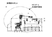
図1〜図3に示すように、本発明の一実施形態に係る超音波探傷装置10は、そのロボットハンド40に、自動探傷器30を用いた超音波探傷試験の対象となるワークWに接触させる探触子P1が取り付けられるものであり、多関節ロボット20(図2参照)と、多関節ロボット20のアーム21に取り付けられるロボットハンド40と、自動探傷用の探触子P1及び手探傷用の探触子P2が取り付けられる自動探傷器30と、多関節ロボット20のロボット制御盤22及び自動探傷器30にデータその他各種信号を授受可能に電気的に接続されるコンピュータ50とを備える。
Hereinafter, an ultrasonic
(
As shown in FIGS. 1 to 3, the ultrasonic
まず、自動探傷器30は、超音波探傷装置10の一部を構成するものであり、コンピュータ50と探触子P1,P2とに接続される。接続される探触子P1,P2の径は10〜25mmであり、送り速度は6〜150mm/secで制御される。ラップ量は0〜100%まで制御可能である。データ記録仕様は、C−Scan画像については自動記録が可能であり、A−Scan画像についてはマニュアル記録が可能である。自動探傷器30のモニタにはA−Scan画像が表示される。
First, the
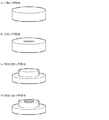
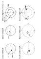
ワークW(図4参照)は、略円柱状の立体形状のものであり、(a)穴無し円形状、(b)穴有り円形状、(c)段付円形状、(d)段付穴有り円形状の4タイプがある。ワークWは、厚みが100mm以上450mm以下、外径が1000mm以上2200mm以下、最大重量が5000kgである。 The workpiece W (see FIG. 4) has a substantially cylindrical solid shape, (a) a circular shape without a hole, (b) a circular shape with a hole, (c) a stepped circular shape, (d) a stepped hole. There are four types of circular shapes. The workpiece W has a thickness of 100 mm to 450 mm, an outer diameter of 1000 mm to 2200 mm, and a maximum weight of 5000 kg.
コンピュータ50は、ロボットハンド40その他当該超音波探傷装置10の各部を制御する制御部(CPU)51と、ロボットハンド40による走査条件(例えば、走査速度及び/又はラップ量をいうが、これに限定されず、走査条件といえるものを少なくとも1種以上含めばよい。)及び試験結果(例えば、走査結果、判定結果等であるが、これに限定されず、試験結果といえるものを少なくとも1種以上含めばよい。)並びに各種制御プログラム及び各種データを記憶するメモリ52と、走査条件を入力するための入力機器53、例えば、キーボードやマウスと、走査条件及び試験結果等を出力するためのモニタ54とを備える。制御部51には、インタフェースを介してロボット制御盤22及び自動探傷器30がこれらに対してデータその他各種信号を授受可能に接続される。
The
図1〜図3に示す多関節ロボット20は、ロングアームタイプの垂直多関節ロボット(6軸)であって、ACサーボモータによる電気サーボ駆動方式のものが好適であるがこれに限定されない。多関節ロボット20は、制御部51及びこれに接続されたロボット制御盤22により制御されるものであり、その制御により、当該多関節ロボット20に取り付けられるアーム21及びロボットハンド40が動作する。また、多関節ロボット20は、自動探傷を行うときにワークWのセンター位置/外径/厚さを検出するためのタッチセンサ23や、超音波探傷試験においてワークWに欠陥が検出された場合にはその欠陥箇所にマーキングを行うスプレー24を備える。従来では、欠陥位置の指示が探触子P1の押し当てであったため時間経過により消えてしまっていたが、マーキングを行うことで時間経過により消えることがなく、これを目印に欠陥箇所の手探傷が可能になる。
The articulated
ロボットハンド40は、探触子ホルダー60と、取付プレート70と、弾性部材80とを備え、探触子ホルダー60が自動探傷器30を用いた超音波探傷試験の対象となるワークWに接触させる探触子P1を保持する。ロボットハンド40は、探触子P1を保持して、ワークWの表面及び/又は裏面を円周方向に走査するものであり、本実施形態においては、ワークWの表面及び/又は裏面を右回り・左回りで交互に円周方向に走査する。ここで、「表面及び/又は裏面」とは、ワークWの片面(表面)の探傷が終了した後、手作業又は自動で反転させてワークWの他面(裏面)の探傷を行う場合を含むことを意味する(以下同じ)。また、ロボットハンド40は、ワークWの表面及び/又は裏面を同心円状に回動動作又は回転動作により円周方向に走査する(図5(a)及び同図(b)参照)。直線的に走査する(同図(c)参照)よりも、円周方向に走査する方が探傷カバー面積を広げるとともに、探傷効率を高めることができるからである。
The
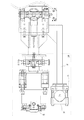
図1〜図3に示す探触子ホルダー60は、探触子P1をその探触子P1の側面から保持するものであり、ロボットハンド40に設けられる取付プレート70を介して多関節ロボット20のアーム21に連結される。探触子ホルダー60は、探触子保持部61と、探触子押圧部62と、フランジ部63と、上部固定部64とを備える。探触子保持部61は、側断面視で略逆L字状の形状であるが、これに限定されるものではない。例えば、側断面視で略逆円弧状のように、保持される探触子P1の外周端角部、外周端段部、外周端縁部、保持される探触子P1の部位が限定されない角部、保持される探触子P1の部位が限定されない段部、保持される探触子P1の部位が限定されない縁部を押圧する又は支持する形状を含むものであればよい。探触子保持部61の内周面は、当該探触子P1の外周面に沿った形状(本実施形態では上面視で円形状、側面視で鉛直線形状)であり、探触子P1の外周側面とは適度なクリアランスがある状態又は密着した状態で対面又は接触する。
The
探触子押圧部62は、探触子P1の上端面周縁部Bを上側から押当て力F(後述する式(1)参照)で押圧するものであり、側断面視で逆略L字状の形状である。このように、探触子ホルダー60は、探触子保持部61が探触子P1を側面から保持し、探触子押圧部62が探触子P1の上端面周縁部Bを押圧するため、探触子P1とワークW面との平行が安定的に維持される。
The
探触子ホルダー60に形成されるフランジ部63には円柱型空間の第一凹部H1が形成されている。取付プレート70は、探触子ホルダー60をロボットハンド40の胴体に取り付けるためのプレートであり、その下面側に円柱型空間の第二凹部H2が形成される。上部固定部64は、座金部64aと、固定ボルト64bとからなり、固定ボルト64bが座金部64a及び探触子保持部61を水平方向に貫通して探触子押圧部62を押さえ込む。これにより、探触子保持部61及び探触子押圧部62が固定される。
The
弾性部材80は、第一凹部H1と第二凹部H2との間に介装される。弾性部材80は、例えば、圧縮コイルバネ、強力スプリング等各種のバネからなり、探触子ホルダー60の周囲に等間隔で複数設けられる。すなわち、第一凹部H1はフランジ部63の周縁部に等間隔で複数設けられるとよく、第二凹部H2は取付プレート70の周縁部に等間隔で複数設けられるとよい。本実施形態においては、探触子ホルダー60の上面視でその中心角度で90°毎に全4個設けられるが、3個以上であればこれに限定されない。弾性部材80により、超音波探傷試験の自動化と相俟って、探触子P1のワークWとの接触面の押当て圧力P(後述する式(2)参照)が均一化される。
The
ここで、探触子P1の押当て力Fについて説明する。押当て力Fは、図1の矢示Aで示す押当て力Fを意味し、次の式(1)で定められる。尚、ここでいうバネとは弾性部材80を指す(図3、図6参照、これらの図の場合n=4)。
押当て力F=バネ定数k×(バネ自由長さL0−バネ取り付け時長さL1−ロボット押し込み長さL2)×バネ取り付け数n … 式(1)
また、押当て圧力Pは、次の式(2)で定められる。
押当て圧力P=押当て力F/ワークWの底面積 … 式(2)
Here, the pressing force F of the probe P1 will be described. The pressing force F means a pressing force F indicated by an arrow A in FIG. 1 and is determined by the following equation (1). The spring here refers to the elastic member 80 (see FIGS. 3 and 6, n = 4 in these drawings).
Pushing force F = spring constant k × (spring free length L0−spring mounting length L1−robot pushing length L2) × spring mounting number n (1)
The pressing pressure P is determined by the following equation (2).
Pushing pressure P = Pushing force F / Bottom area of work W Equation (2)
以上の構成により、ロボットハンド40は、超音波探傷試験の対象となるワークWに接触させる探触子P1が取り付けられ、メモリ52に記憶された走査条件に従って、制御部51及びロボット制御盤22により制御され、ワークWの表面及び/又は裏面を円周方向に右方向・左方向交互に同心円状に走査する。試験結果は制御部51による制御のもとメモリ52に記憶される。そのため、走査条件が定量化されるとともに、試験結果が記録として残る。また、超音波探傷試験の自動化が図られるため、超音波探傷試験の信頼性が高まるとともに高効率化が図られる。
With the above configuration, the
従って、本発明の一実施形態に係る超音波探傷装置10によれば、探触子P1とワークWの表面及び/又は裏面との平行関係が安定的に保たれるとともに、探触子P1のワークWとの接触面の押当て圧力Pが均一化されるため、探触子保持部61と探触子P1とのクリアランス分の探触子P1の傾きが少量化される。そのため、超音波探傷試験が従来よりも正確に行うことが可能になり、超音波探傷試験における内部欠陥の見逃しが無くなる。これにより、ワークW(例えば、翼車板)の品質保証に対する信頼性が高められる。
Therefore, according to the
(第二の実施形態に係る超音波探傷装置10)
図6に示す超音波探傷装置10について説明する。符号については超音波探傷装置10と同じ部材については同じ符号を用いて説明する。
探触子ホルダー60は、探触子P1をその探触子P1の側面から保持するものであり、ロボットハンド40に設けられる取付プレート70を介して多関節ロボット20のアーム21に連結される。探触子ホルダー60は、探触子保持部61と、探触子押圧部62と、フランジ部63と、上部固定部64とを備える。探触子保持部61は、側断面視で略逆L字状の形状である。探触子保持部61の内周面は、当該探触子P1の外周面に沿った形状(本実施形態では上面視で円形状、下部Lが側面視で鉛直線状、上部Uが側面視で下部が円弧状に湾曲した略鉛直線状)であり、探触子P1の外周側面とは適度なクリアランスがある状態又は密着した状態で対面又は接触する。
(
The
The
探触子押圧部62は、探触子P1の下部Lの上端面周縁部Bを上側から押当て力Fで押圧するものであり、探触子保持部61の段部Kによって構成される。このように、探触子押圧部62は探触子保持部61の一部によって構成してもよい。すなわち、探触子押圧部62の段部Kは、側断面視で略逆L字状であるが、これに限定されるものではない。例えば、側断面視で略逆円弧状のように、保持される探触子P1の外周端角部、外周端段部、外周端縁部、保持される探触子P1の部位が限定されない角部、保持される探触子P1の部位が限定されない段部、保持される探触子P1の部位が限定されない縁部を押圧する又は支持する形状を含むものであればよい。これにより、探触子ホルダー60は、探触子保持部61が探触子Pを側面から保持し、探触子押圧部62が探触子Pの上端面周縁部Bを押圧するため、探触子PとワークW面との平行が安定的に維持される。
The
探触子ホルダー60に形成されるフランジ部63には円柱型空間の第一凹部H1が形成されている。取付プレート70は、探触子ホルダー60をロボットハンド40の胴体に取り付けるためのプレートであり、その下面側に円柱型空間の第二凹部H2が形成される。上部固定部64は、座金部64aと、固定ボルト64bとからなり、固定ボルト64bが座金部64a及び探触子保持部61を鉛直方向に挿通して探触子押圧部62を押さえ込む。これにより、探触子保持部61及び探触子押圧部62が固定される。
The
弾性部材80は、第一凹部H1と第二凹部H2との間に介装される。弾性部材80は、例えば、圧縮コイルバネ、強力スプリング等各種のバネからなり、探触子ホルダー60の周囲に等間隔で複数設けられる。すなわち、第一凹部H1はフランジ部63の周縁部に等間隔で複数設けられるとよく、第二凹部H2は取付プレート70の周縁部に等間隔で複数設けられるとよい。本実施形態においては、探触子ホルダー60の上面視でその中心角度で90°毎に全4個設けられるが、3個以上であればこれに限定されない。弾性部材80により、超音波探傷試験の自動化と相俟って、探触子P1のワークWとの接触面の押当て圧力Pが均一化される。
その他の構成については第一の実施形態に係る超音波探傷装置10と同様であるためその説明を省略する。
The
Since other configurations are the same as those of the
(第三の実施形態に係る超音波探傷装置10)
図7Aから図7Cは、第三の実施形態にかかる超音波探傷装置10を示し、スプレー24を取り付けた場合の具体例を示す。図7Aは正面図、図7Bは側面図、図7Cは平面図(上から見た図)である。
スプレー24は、スプレーホルダー90で保持され、ブラケット91を介してロボットハンド40に機械的・電気的に連結・接続される。スプレー24は、後述するように(図8参照)、自動探傷において欠陥が検出された場合に欠陥箇所にスプレーでマーキングを行う。
(
FIG. 7A to FIG. 7C show the
The
このマーキングは、次のようにしてなされる。まず、探触子P1は電子制御又は手作業により移動させる。次に、スプレー24は、そのスプレーノズル25が欠陥箇所の上に来るように電子制御により移動させる。そして、スプレースイッチ26が電子制御により押下されスプレー液が噴射される。このスプレー液は、消えないため、その後の手探傷(図8参照)での作業において探傷箇所の特定を正確に行うことができる。その他の構成は、第二の実施形態と同様であるため省略する。
This marking is performed as follows. First, the probe P1 is moved by electronic control or manual work. Next, the
(超音波探傷方法)
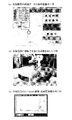
図8のフローチャートを参照して本発明の一実施形態に係る超音波探傷方法、すなわち、超音波探傷装置10を用いて自動探傷を行う工程と、この自動探傷において欠陥が検出された場合にはその欠陥箇所に対して手探傷を行う工程とからなる方法について説明する。尚、同図のフローチャートは超音波探傷方法の工程の一例であり、これに限定されない。
(Ultrasonic flaw detection method)
With reference to the flowchart of FIG. 8, an ultrasonic flaw detection method according to an embodiment of the present invention, that is, a step of performing automatic flaw detection using the ultrasonic
まず、電源投入工程(S1)において、超音波探傷装置10その他関係設備の電源が投入される。これにより、超音波探傷装置10その他関係設備は、各部の初期設定並びに稼働準備を行い、運転可能状態となり、S2の工程へ進む。
ワーク搬入工程(S2)では、超音波探傷を行うワークWが搬入され、所定の位置へセットされた後、S3の工程へ進む。
First, in the power-on process (S1), the
In the workpiece loading step (S2), the workpiece W to be subjected to ultrasonic flaw detection is loaded and set at a predetermined position, and then the process proceeds to step S3.
探触子セット工程(S3)では、ワークWが探触子ホルダー60に取り付けられ、探触子P1が所定の位置にセットされた後、S4の工程へ進む。
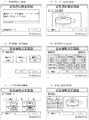
次に、各設定値入力工程(S4)では、図9に示すモニタ54の入力画面に従って入力がなされる。同図に示すように、
(1)識別情報入力画面にて、識別情報(保存ファイル番号へ反映されるものであり、バーコードリーダにて読み込みがなされる)が入力され、次に、
(2)使用探触子選択画面にて、使用する探触子の選択がなされ、次に、
(3)ワーク形状選択画面にて、形状(図4参照)及び表面/裏面の選択がなされ、次に、
(4)ワーク寸法入力画面にて、外径/高さが入力される他、必要に応じて、内径/段部寸法が入力され、次に、
(5)走査条件入力画面にて、ラップ量(0〜100%)、走査速度(半径毎に設定可)、判定基準値が入力され、次に、
(6)各設定値確認画面にて、各設定値が確認され、その後、S5の工程へ進む。
In the probe setting step (S3), the work W is attached to the
Next, in each set value input step (S4), input is performed according to the input screen of the
(1) On the identification information input screen, identification information (which is reflected in the saved file number and read by the barcode reader) is input,
(2) The probe to be used is selected on the use probe selection screen.
(3) On the workpiece shape selection screen, the shape (see FIG. 4) and the front / back surface are selected.
(4) On the workpiece dimension input screen, the outer diameter / height is entered, and if necessary, the inner diameter / step dimension is entered.
(5) On the scanning condition input screen, the lapping amount (0 to 100%), the scanning speed (can be set for each radius), and the criterion value are input.
(6) Each set value is confirmed on each set value confirmation screen, and then the process proceeds to step S5.
センシング&キャリブレーション工程(S5)では、多関節ロボット20の自動動作によるセンシングとキャリブレーションがなされる。センシングにおいては、ワーク寸法入力値より外側(例えば、外周縁から200mm外側)からタッチセンサ23により、ワークWのセンター位置/外径/厚さの検出がなされる。その後のキャリブレーションにおいては、入力外径より内側(例えば、外周縁より100mm内側)の箇所が円弧状に走査され、モニタ31の出力画像に基づいて作業員による探傷器感度等の調整がなされる。その後、S6の工程へ進む。
In the sensing and calibration step (S5), sensing and calibration are performed by automatic operation of the articulated
設定情報最終確認工程(S6)では、設定情報の最終確認がなされ、S7の工程に進む。
自動探傷工程(S7)では、ロボットハンド40(探触子P1)によりワークWの表面及び/又は裏面が右回り・左回りで交互に円周方向・同心円状に走査される。交互に回転方向が変わることにより多関節ロボット20の小型化(省スペース及び省コスト化)が可能になる。その後、S8の工程に進む。
In the setting information final confirmation step (S6), the setting information is finally confirmed, and the process proceeds to step S7.
In the automatic flaw detection process (S7), the robot hand 40 (probe P1) scans the front and / or back surfaces of the workpiece W alternately in the circumferential direction and concentric circles in the clockwise and counterclockwise directions. By alternately changing the rotation direction, the articulated
自動探傷完了結果出力工程(S8)では、自動探傷器30にはA−Scan画像が表示される(図10(a)参照)。欠陥検出ゲートにより欠陥の有無が分かる。ワークWの上面視での具体的な試験結果は、モニタ54に同図(b)や同図(c)に示す態様で表示される。これらの図は欠陥がある場合を示し、欠陥箇所のみを表示させることもできる(図12参照)。尚、エコー強さ(%)は上記のS4の工程で任意に設定が可能であり、判定基準は要求精度に合わせて設定可能である。また、同図(b)及び同図(c)に示す結果1及び結果2はマウスクリック等により切り換え可能である。表示選択のエコー強さ(%)は任意に設定を変更することができる。その後、S9の工程に進む。
In the automatic flaw detection completion result output step (S8), an A-Scan image is displayed on the automatic flaw detector 30 (see FIG. 10A). The presence or absence of a defect can be determined by the defect detection gate. The specific test result of the workpiece W as viewed from above is displayed on the
欠陥検出判定工程(S9)においては、S8での結果出力に基づいて欠陥検出がなされる。その結果欠陥が検出されなかったと判断された場合には、S10のデータ保存工程へ進み、メモリ52に自動探傷結果が記録される。
一方、欠陥が検出されたと判断された場合には、S11の欠陥箇所指示工程へ進む。ここではモニタ54及びモニタ31に欠陥部の詳細データ表示画面(図11参照)が表示されるとともに、スプレー24によるマーキングがなされ、S12へ進む。
S12においては、マーキングがなされた箇所の手探傷が行われる。これにより、欠陥の詳細状態が確認される。また、手探傷結果は、メモリ52に保存される。
In the defect detection determination step (S9), defect detection is performed based on the result output in S8. As a result, if it is determined that no defect has been detected, the process proceeds to the data storage step of
On the other hand, if it is determined that a defect has been detected, the process proceeds to the defect location indicating step of S11. Here, a detailed data display screen (see FIG. 11) of the defective portion is displayed on the
In S12, the hand flaw detection of the marked part is performed. Thereby, the detailed state of the defect is confirmed. The result of manual flaw detection is stored in the
超音波探傷装置10を用いて超音波探傷試験を行ったのでそれについて説明する。表1及び図12に示すように、実施例Aは、超音波探傷試験を全自動超音波探傷装置を用いて実施したもの(比較例1)と超音波探傷装置10を用いて実施したもの(実施例1)とを比較検証したものである。実施例Bは超音波探傷試験を手探傷で実施したもの(実施例2’)と超音波探傷装置10を用いて実施したもの(実施例2)とを比較検証したものである。実施例Cは人工欠陥テストピース(既に欠陥箇所が判明済みの比較例3)と超音波探傷装置10を用いて実施したもの(実施例3)とを比較検証したものである。表1にはワーク仕様、検査条件、検査結果等を示し、図12には超音波探傷試験の結果画面情報を示す。
An ultrasonic flaw detection test was performed using the ultrasonic
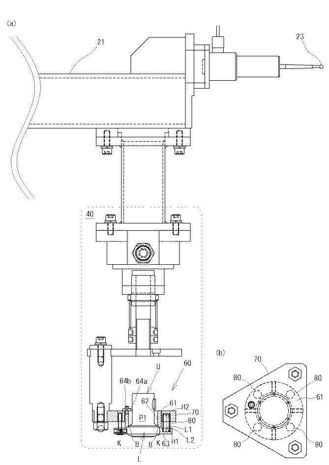
表1及び図12に示したように、実施例A及び実施例Cでは各比較例と各実施例との欠陥情報が一致した。このことから、実施例に係る超音波探傷装置10の精度が良好であることが確認できた。
実施例Bでは、実施例2’で2箇所の位置が検出されたが、実施例2では1箇所の位置が検出され結果が異なった。これは欠陥箇所が近かったためである。このことから、超音波探傷試験においては、超音波探傷装置10を用いて自動探傷を行った後、手探傷により欠陥箇所を確認する方法が有効であることが確認できた。
As shown in Table 1 and FIG. 12, in Example A and Example C, the defect information in each comparative example and each example coincided. From this, it was confirmed that the accuracy of the
In Example B, two positions were detected in Example 2 ′, but in Example 2, one position was detected and the results were different. This is because the defective part was close. From this, in the ultrasonic flaw detection test, after performing automatic flaw detection using the ultrasonic
以上、本発明の一実施形態について説明したが、本発明は上記実施の形態に何ら限定されるものではない。本発明は、上記実施形態を逸脱しない範囲で種々の改変が可能である。 Although one embodiment of the present invention has been described above, the present invention is not limited to the above embodiment. The present invention can be variously modified without departing from the above embodiment.
本発明に係る超音波探傷装置及びこれを用いた超音波探傷方法は、高精度検査が要求される翼車板の製造メーカー関係各社での利用価値が見込まれる。 The ultrasonic flaw detection apparatus and the ultrasonic flaw detection method using the same according to the present invention are expected to be useful in various manufacturers related to impeller plates that require high-precision inspection.
Claims (7)
前記探触子を側面から保持する探触子保持部であってその内周面が当該探触子の外周面に沿った形状の探触子保持部と、前記探触子の上端面周縁部を押圧する探触子押圧部と、フランジ部に形成された第一凹部とを備えた探触子ホルダーと、
前記探触子ホルダーを前記ロボットハンド胴体に取り付ける取付プレートであってその下面側に形成された第二凹部を備えた取付プレートと、
前記第一凹部と前記第二凹部との間に介装される弾性部材と、
を備えたことを特徴とする超音波探傷装置。 A robot hand to which a probe to be brought into contact with a workpiece to be subjected to an ultrasonic flaw detection test is attached, the robot hand scanning the surface and / or the back surface of the workpiece in the circumferential direction, the robot hand and the other ultrasonic flaw detection. An articulated robot comprising control means for controlling each part of the apparatus, and storage means for storing scanning conditions and test results by the robot hand;
A probe holding portion for holding the probe from the side surface, the inner peripheral surface of the probe holding portion having a shape along the outer peripheral surface of the probe, and the upper end surface peripheral portion of the probe A probe holder including a probe pressing portion that presses the first recess, and a first recess formed in the flange portion;
An attachment plate for attaching the probe holder to the robot hand body and having a second recess formed on the lower surface thereof; and
An elastic member interposed between the first recess and the second recess;
An ultrasonic flaw detector characterized by comprising:
前記自動探傷工程において欠陥が検出された場合にはその欠陥箇所に対して手探傷を行う手探傷工程とを備えたことを特徴とする超音波探傷方法。 An automatic flaw detection process for performing automatic flaw detection using the ultrasonic flaw detector according to any one of claims 1 to 5,
An ultrasonic flaw detection method comprising: a manual flaw detection step of performing a flaw detection on a defective portion when a defect is detected in the automatic flaw detection step.
Priority Applications (1)
| Application Number | Priority Date | Filing Date | Title |
|---|---|---|---|
| JP2012044008A JP2013181767A (en) | 2012-02-29 | 2012-02-29 | Ultrasonic flaw detection apparatus and ultrasonic flaw detection method using the same |
Applications Claiming Priority (1)
| Application Number | Priority Date | Filing Date | Title |
|---|---|---|---|
| JP2012044008A JP2013181767A (en) | 2012-02-29 | 2012-02-29 | Ultrasonic flaw detection apparatus and ultrasonic flaw detection method using the same |
Publications (1)
| Publication Number | Publication Date |
|---|---|
| JP2013181767A true JP2013181767A (en) | 2013-09-12 |
Family
ID=49272537
Family Applications (1)
| Application Number | Title | Priority Date | Filing Date |
|---|---|---|---|
| JP2012044008A Pending JP2013181767A (en) | 2012-02-29 | 2012-02-29 | Ultrasonic flaw detection apparatus and ultrasonic flaw detection method using the same |
Country Status (1)
| Country | Link |
|---|---|
| JP (1) | JP2013181767A (en) |
Cited By (1)
| Publication number | Priority date | Publication date | Assignee | Title |
|---|---|---|---|---|
| CN109358114A (en) * | 2018-11-16 | 2019-02-19 | 四川聚亿重工有限公司 | A kind of test of flaw detection system of turbocompressor blade |
-
2012
- 2012-02-29 JP JP2012044008A patent/JP2013181767A/en active Pending
Cited By (1)
| Publication number | Priority date | Publication date | Assignee | Title |
|---|---|---|---|---|
| CN109358114A (en) * | 2018-11-16 | 2019-02-19 | 四川聚亿重工有限公司 | A kind of test of flaw detection system of turbocompressor blade |
Similar Documents
| Publication | Publication Date | Title |
|---|---|---|
| JP4620119B2 (en) | measuring device | |
| JP4839333B2 (en) | Ultrasonic inspection method and ultrasonic inspection apparatus | |
| CN106814135B (en) | The phased array supersonic automatic testing method of electric arc plug welds | |
| CN101672829B (en) | Method for measuring parameter of omega welding seam defect | |
| JP2008528982A (en) | Turbine component defect detection method and apparatus | |
| JP2007187593A (en) | Inspection device for piping and inspection method for piping | |
| KR20160096124A (en) | System and method for inspection of components | |
| JP5868198B2 (en) | Ultrasonic flaw detection apparatus and ultrasonic flaw detection method for welds | |
| CN104730145A (en) | Method for accurately positioning defects of material during ultrasonic detection | |
| JP5622597B2 (en) | Ultrasonic flaw detection apparatus and ultrasonic flaw detection method | |
| JP5530975B2 (en) | Ultrasonic flaw detection method and ultrasonic flaw detection apparatus | |
| US11422116B2 (en) | Robot system and method for non-destructive testing | |
| JP4897420B2 (en) | Ultrasonic flaw detector | |
| JP2011174864A (en) | Sensor pressing tool, and method of verifying adhesion of sensor and method of detecting flaw using the sensor pressing tool | |
| KR20100076636A (en) | Multi channel ultrasonic welding inspection system and control method | |
| JP2013181767A (en) | Ultrasonic flaw detection apparatus and ultrasonic flaw detection method using the same | |
| US20220313216A1 (en) | Augmented reality in ultrasonic inspection | |
| KR101867704B1 (en) | Ultrasonic testing apparatus | |
| JP2008076129A (en) | Ultrasonic inspection method and ultrasonic inspection device | |
| JPH09325136A (en) | Automatic defect evaluating method for centrifugal type impeller | |
| JP4699242B2 (en) | Ultrasonic probe coupling check method and computer program | |
| WO2019091029A1 (en) | Phased array ultrasonic testing method for weld seam of housing welded by using aluminum alloy | |
| CN114324578A (en) | Ferrite steel container sheet butt weld phased array ultrasonic detection method | |
| KR101159009B1 (en) | Zirconium tube testing apparatus and tube testing method the same | |
| JP3745628B2 (en) | Welded part inspection method and ultrasonic flaw detector |