JP2013176331A - Seedling transplanter - Google Patents

Seedling transplanter Download PDF

Info

Publication number
JP2013176331A
JP2013176331A JP2012042616A JP2012042616A JP2013176331A JP 2013176331 A JP2013176331 A JP 2013176331A JP 2012042616 A JP2012042616 A JP 2012042616A JP 2012042616 A JP2012042616 A JP 2012042616A JP 2013176331 A JP2013176331 A JP 2013176331A
Authority
JP
Japan
Prior art keywords
rotor
leveling
seedling
vertical movement
planting
Prior art date
Legal status (The legal status is an assumption and is not a legal conclusion. Google has not performed a legal analysis and makes no representation as to the accuracy of the status listed.)
Granted
Application number
JP2012042616A
Other languages
Japanese (ja)
Other versions
JP2013176331A5 (en
JP5957953B2 (en
Inventor
Makoto Yamaguchi
信 山口
Manabu Takahashi
学 高橋
Takayuki Fujishiro
孝行 藤代
Current Assignee (The listed assignees may be inaccurate. Google has not performed a legal analysis and makes no representation or warranty as to the accuracy of the list.)
Iseki and Co Ltd
Iseki Agricultural Machinery Mfg Co Ltd
Original Assignee
Iseki and Co Ltd
Iseki Agricultural Machinery Mfg Co Ltd
Priority date (The priority date is an assumption and is not a legal conclusion. Google has not performed a legal analysis and makes no representation as to the accuracy of the date listed.)
Filing date
Publication date
Application filed by Iseki and Co Ltd, Iseki Agricultural Machinery Mfg Co Ltd filed Critical Iseki and Co Ltd
Priority to JP2012042616A priority Critical patent/JP5957953B2/en
Publication of JP2013176331A publication Critical patent/JP2013176331A/en
Publication of JP2013176331A5 publication Critical patent/JP2013176331A5/ja
Application granted granted Critical
Publication of JP5957953B2 publication Critical patent/JP5957953B2/en
Active legal-status Critical Current
Anticipated expiration legal-status Critical

Links

Images

Abstract

PROBLEM TO BE SOLVED: To provide a seedling transplanter, preventing breakage of a ground leveling device 27 and an elevating link mechanism 3, and also improving the durability of constituent members.SOLUTION: When a seedling tank 51 is operated to rise, a ground leveling rotor vertical motion mechanism R is operated so that the ground leveling device 27 rises as a whole. In this state, the ground leveling device 27 is put in the attitude of lowering forward by the weight of a center ground leveling rotor 27b to prevent the load from being applied to the ground leveling device 27 and the elevating link mechanism 3. Thus, the breakage of the ground leveling device 27, the elevating link mechanism 3 and so on can be prevented, and the durability of the constituent members is improved.

Description

この発明は、走行装置を有する機体の後部に苗植付部を備えた苗移植機に関する。   The present invention relates to a seedling transplanting machine provided with a seedling planting part at the rear part of a machine body having a traveling device.

苗植付部を機体後部に備えた苗移植機において、苗移植機が圃場を前進走行しながら苗を圃場に植え付けるに当たって圃場面を整地する整地ロータを苗植付部に設けた構成が知られている(特許文献1)。   In a seedling transplanter equipped with a seedling planting part at the rear part of the aircraft, it is known that a seedling transplanting unit is provided with a leveling rotor for leveling the field scene when the seedling transplanting machine is traveling forward in the field and planting seedlings in the field. (Patent Document 1).

特開2011−44号公報JP 2011-44 JP

特許文献1記載の構成からなる苗移植機には、中央の整地ロータと左右の整地ロータからなる整地装置を備え、この整地装置で苗の植付位置やフロートの前側の圃場面の整地を行う構成としている。
上記構成の整地装置は、旋回時等に苗植付部を上昇させると、それに連動して上方に移動する構成とされているが、中央の整地ロータが左右の整地ロータよりも前方に配置されているため、苗植付部の上昇量が多くなると重量により前方に傾斜しやすく、中央の整地ロータを吊り下げるスプリングや、このスプリングを取り付けるプレートが負荷で破損しやすいという問題がある。
The seedling transplanting machine having the configuration described in Patent Document 1 includes a leveling device including a center leveling rotor and left and right leveling rotors, and performs leveling of a seedling planting position and a field scene in front of the float with this leveling device. It is configured.
The leveling device having the above configuration is configured to move upward in conjunction with raising the seedling planting part during turning or the like, but the central leveling rotor is disposed in front of the left and right leveling rotors. Therefore, when the amount of raising of the seedling planting portion increases, there is a problem that the spring tends to tilt forward due to the weight, and the spring for hanging the ground leveling rotor and the plate to which the spring is attached are easily damaged by the load.

また、整地装置が所定高さ以上に上昇した際、苗植付部を上下動させる昇降リンク機構に接触することを防止すべく、スプリングの取付プレートにカムローラを回転自在に設けている。
これにより、所定高さまで植付装置が昇降するとそれ以上の上昇は阻止されるが、接触抵抗は上昇に伴い大きくなるため、長期の使用によりカムローラの軸や昇降リンク機構が変形してしまう問題がある。
In addition, a cam roller is rotatably provided on the spring mounting plate in order to prevent contact with an elevating link mechanism that moves the seedling planting portion up and down when the leveling device rises above a predetermined height.
As a result, when the planting device moves up and down to a predetermined height, further increase is prevented, but the contact resistance increases with the increase, so that there is a problem that the shaft of the cam roller and the lifting link mechanism are deformed by long-term use. is there.

上記整地装置は、レバーを手動操作して上下位置を変更する構成であるが、整地装置は重量物であるため、作業者の労力を増大させる問題があると共に、細やかな変更が難しく、圃場条件によっては整地装置の機能が大きく低下する問題がある。
そこで本発明の課題は、整地装置の上下動を操縦者に負担を掛けないで行うことができ、整地装置とその関連部材を耐久性のある構成とした苗移植機を提供することである。
The leveling device is configured to change the vertical position by manually operating the lever. However, since the leveling device is heavy, there is a problem of increasing the labor of the operator, and it is difficult to make detailed changes. Depending on the situation, there is a problem that the function of the leveling device is greatly reduced.
SUMMARY OF THE INVENTION An object of the present invention is to provide a seedling transplanting machine in which the leveling device can be moved up and down without placing a burden on the operator, and the leveling device and its related members have a durable configuration.

上記課題は、下記構成によって達成される。
請求項1に係る発明は、圃場を走行する走行車体(2)と、エンジン(20)と、該エンジン(20)からの駆動力を変速する変速装置を収納したミッションケース(12)と、該ミッションケース(12)からの駆動力を左右の後輪(11)に伝動する後輪伝動(ギヤ)ケース(18)と、圃場面を均す中央整地ロータ(センタロータ)(27b)と該中央整地ロータ(センタロータ)(27b)の左右両側、且つ後側で圃場面を均す左右の側方整地ロータ(サイドロータ)(27a,27a)を一体的に設けた整地装置(27)と、後輪伝動(ギヤ)ケース(18)からの駆動力を左右の側方整地装置(サイドロータ)(27a)の中のどちらか一側に伝動させるための駆動シャフト(27)と、走行車体(2)の後部に昇降リンク機構(3)と、該昇降リンク機構(3)の後部に苗を積載する複数条の苗タンク(苗載台)(51)と、各苗タンク(苗載台)(51)から苗を取って圃場に植え付ける複数条の植付装置(52)とを設けた苗移植機において、前記左右の側方整地ロータ(サイドロータ)(27a)の中のいずれか一方に連結して、整地装置(27)全体の上下位置を変更する左右一対の整地ロータ上下動機構(R)を設けたことを特徴とする苗移植機である。
The said subject is achieved by the following structure.
The invention according to claim 1 includes a traveling vehicle body (2) that travels in a field, an engine (20), a transmission case (12) that houses a transmission that shifts driving force from the engine (20), A rear wheel transmission (gear) case (18) for transmitting the driving force from the transmission case (12) to the left and right rear wheels (11), a central leveling rotor (center rotor) (27b) for leveling the field scene, and the center A leveling device (27) integrally provided with left and right side leveling rotors (27a, 27a) for leveling the farm scene on the left and right sides of the leveling rotor (center rotor) (27b) and the rear side; A driving shaft (27) for transmitting the driving force from the rear wheel transmission (gear) case (18) to either one of the left and right lateral leveling devices (side rotor) (27a), and a traveling vehicle body ( 2) Elevating link mechanism at the rear 3), a plurality of seedling tanks (seedling stage) (51) for loading seedlings at the rear of the elevating link mechanism (3), and seedlings from each seedling tank (seedling stage) (51) In a seedling transplanter provided with a plurality of planting devices (52) to be planted on the ground, the ground leveling device (27) is connected to one of the left and right lateral leveling rotors (side rotors) (27a). A seedling transplanting machine provided with a pair of left and right leveling rotor vertical movement mechanisms (R) for changing the overall vertical position.

請求項2に係る発明は、前記昇降リンク機構(3)に現在の昇降位置を検知する昇降位置検知部材(昇降リンクセンサ)(94)を設け、該昇降位置検知部材(昇降リンクセンサ)(94)による昇降リンク機構(3)の昇降時の検知角度から苗タンク(苗載台)(51)の上下位置を識別して、前記苗タンク(51)の上下位置が所定位置(例:地表50cm付近)に下降すると、整地ロータ上下動装置(R)を作動させて整地装置(27)を圃場に下降させる制御を行う制御装置(100)を備えたことを特徴とする請求項1記載の苗移植機である。   The invention according to claim 2 is provided with a lift position detecting member (lift link sensor) (94) for detecting a current lift position in the lift link mechanism (3), and the lift position detecting member (lift link sensor) (94). ) To identify the vertical position of the seedling tank (seedling stage) (51) from the detected angle when the vertical movement mechanism (3) is raised and lowered, and the vertical position of the seedling tank (51) is a predetermined position (eg, 50 cm above the ground) The seedling according to claim 1, further comprising a control device (100) for controlling the leveling device (27) to be lowered to the field by operating the leveling rotor vertical movement device (R) when the leveling device is lowered to the vicinity. It is a transplanter.

請求項3に係る発明は、前記左右の側方整地装置(サイドロータ)(27a,27a)に整地装置(27)全体を持ち上げるためのロータ持上げロッド(91,91)の下部を連結し、該左右のロータ持上げロッド(91,91)の上部に左右のロータ上下動アーム(86,86)の一端部側を連結し、該左右のロータ上下動アーム(86,86)の一端部を苗タンク(苗載台)(51)に支持された回動軸(89)に装着し、前記左右の側方整地ロータ(27a,27a)のうち、駆動シャフト(72)を設けた側方整地ロータ(27a)側に前記整地ロータ上下動装置(R)を構成する扇形ギヤ(85)とロータ上下動モータ(83)を配置することを特徴とする請求項2記載の苗移植機である。   The invention according to claim 3 connects the lower part of the rotor lifting rod (91, 91) for lifting the entire leveling device (27) to the left and right side leveling devices (side rotor) (27a, 27a), One end of the left and right rotor vertical movement arms (86, 86) is connected to the upper part of the left and right rotor lifting rods (91, 91), and one end of the left and right rotor vertical movement arms (86, 86) is connected to a seedling tank. (Seedling stand) (51) Attached to the rotating shaft (89), of the left and right side leveling rotors (27a, 27a), a side leveling rotor (provided with a drive shaft (72)) ( The seedling transplanter according to claim 2, wherein a fan-shaped gear (85) and a rotor vertical movement motor (83) constituting the leveling rotor vertical movement device (R) are arranged on the 27a) side.

請求項4に係る発明は、前記ロータ上下動アーム(86,86)とロータ持上げロッド(91,91)の間に退避回動アーム(90,90)を設け、該退避回動アーム(90,90)をロータ持上げロッド(91,91)に設けた回動支点(90a,90a)を中心に上下回動自在に装着し、該退避回動アーム(90,90)は正面視L字形に形成し、ロータ上下動アーム(86,86)の一側面と上方を覆う形状としたことを特徴とする請求項2記載の苗移植機である。   According to a fourth aspect of the present invention, a retraction rotation arm (90, 90) is provided between the rotor vertical movement arm (86, 86) and the rotor lifting rod (91, 91), and the retraction rotation arm (90, 90) is provided. 90) is mounted on the rotor lifting rod (91, 91) so as to be pivotable up and down around the pivot fulcrum (90a, 90a), and the retracting pivot arm (90, 90) is formed in an L shape when viewed from the front. The seedling transplanter according to claim 2, wherein the seedling transplanter has a shape that covers one side and an upper side of the rotor vertical movement arm (86, 86).

請求項5に係る発明は、苗タンク(苗載台)(51)の下部(例えば、植付装置52の植付伝動ケース(95)の下部に設けたポテンショメータ)に圃場の凹凸に追従して上下回動する接触検知プレート(96)と、該接触検知プレート(96)を側方整地ロータ(27a)の非整地位置(ロータを構成する回転体のうち、意図的に間隔を空けている部分があり、その部分ことを言う。)を通して圃場面に先端部を接触させ、接触検知プレートの基部に取り付けた該接触検知プレート(96)の上下回動量を検出する接触検知プレートポテンショメータ(81)(例:15〜30度を検知すると信号を発信)と、該接触検知プレートポテンショメータ(81)で検出される接触検知プレート(96)の上下回動量が所定値になると、昇降油圧シリンダ(46)が苗タンク(51)を自動的に、所定量上昇させる制御構成を有する制御装置(100)を備えた請求項1記載の苗移植機である。   The invention which concerns on Claim 5 follows the unevenness | corrugation of a field in the lower part (For example, the potentiometer provided in the lower part of the planting transmission case (95) of the planting apparatus 52) of the seedling tank (seedling mounting stand) (51). A contact detection plate (96) that rotates up and down, and a non-leveling position of the side leveling rotor (27a) with the contact detection plate (96) (a part of the rotating body constituting the rotor that is intentionally spaced) A contact detection plate potentiometer (81) for detecting the amount of vertical rotation of the contact detection plate (96) attached to the base of the contact detection plate. Example: When a signal of 15 to 30 degrees is detected, a signal is transmitted), and when the vertical rotation amount of the contact detection plate (96) detected by the contact detection plate potentiometer (81) reaches a predetermined value, the lift hydraulic pressure Linda (46) is automatically seedling tank (51), a seedling transplantation machine of claim 1, further comprising a control device (100) having a control arrangement for increasing a predetermined amount.

請求項1記載の発明によれば、苗タンク51を上昇操作すると整地ロータ上下動機構Rが作動し、整地装置27が全体に上昇するが、中央整地ロータ27bの重量で整地装置27は前下がり姿勢になり、整地装置27や昇降リンク機構3などに負荷がかかることを防止できるので、整地装置27や昇降リンク機構3などの破損が防止されると共に、構成部材の耐久性が従来技術より向上する。   According to the first aspect of the present invention, when the seedling tank 51 is lifted, the leveling rotor vertical movement mechanism R is activated and the leveling device 27 rises as a whole, but the leveling device 27 is lowered forward by the weight of the central leveling rotor 27b. Since it becomes a posture and it can prevent that a load is applied to the leveling device 27, the raising / lowering link mechanism 3, etc., damage to the leveling device 27, the raising / lowering link mechanism 3, etc. is prevented, and durability of a structural member improves from a prior art. To do.

請求項2記載の発明によれば、請求項1記載の発明の効果に加えて、整地装置27の下降移動距離が苗タンク51や植付装置52の下降移動距離よりも長くなると整地装置27が土中に入り込み、損傷するおそれがある。しかし、苗タンク51を下降させ、所定位置まで下降した段階で整地ロータ上下動装置Rを作動させて整地装置27を下降させることにより、整地装置27の下降移動距離が苗タンク51や植付装置52の下降移動距離よりも長くなることがなくなり、整地装置27が土中に入り込まなくなるため、整地装置27が圃場面を荒らすことが防止される。   According to the invention described in claim 2, in addition to the effect of the invention described in claim 1, when the descending movement distance of the leveling device 27 becomes longer than the descending movement distance of the seedling tank 51 and the planting device 52, the leveling device 27 There is a risk of entering the soil and damaging it. However, when the seedling tank 51 is lowered, and the leveling rotor vertical movement device R is operated to lower the leveling device 27 when the seedling tank 51 is lowered to a predetermined position, the downward movement distance of the leveling device 27 is changed to the seedling tank 51 and the planting device. 52, the leveling device 27 is prevented from entering the soil, and the leveling device 27 is prevented from roughing the field scene.

請求項3記載の発明によれば、請求項2記載の発明の効果に加えて、整地ロータ上下動機構Rを構成する扇形ギヤ85とロータ上下動モータ83を、駆動シャフト72が駆動力を供給する側方整地ロータ27a側に設けたことにより、駆動部品が一方に集中するため、メンテナンス時に作業を集中的に行うことができる。
また、左右のロータ上下動アーム86を一つの回動軸20に装着したことにより、扇形ギヤ85とロータ上下動モータ83を一対設けられる整地ロータ上下動機構Rの左右どちらか一方に配置すればよいため、構成部品が減少し、メンテナンス性の向上や機体の軽量化が図られる。
According to the invention described in claim 3, in addition to the effect of the invention described in claim 2, the drive shaft 72 supplies driving force to the sector gear 85 and the rotor vertical movement motor 83 that constitute the leveling rotor vertical movement mechanism R. Since the drive parts are concentrated on one side by providing the side leveling rotor 27a, the work can be concentrated during maintenance.
Further, by mounting the left and right rotor vertical movement arms 86 on one rotating shaft 20, if the sector gear 85 and the rotor vertical movement motor 83 are disposed on either the left or right side of the leveling rotor vertical movement mechanism R provided as a pair. As a result, the number of components is reduced, and maintenance is improved and the weight of the aircraft is reduced.

請求項4記載の発明によれば、請求項2記載の発明の効果に加えて、ロータ上下動アーム86の一側面と上方を覆う配置で退避回動アーム90を設け、このロータ上下動アーム86とロータ持上げロッド91の間に退避回動アーム90を設けたことにより、整地装置27が段差や石などに乗り上げて大きく上昇して、ロータ持上げロッド91がロータ持上げロッド91に設けた回動支点91aを中心に上方移動するので、ロータ上下動アーム86は回動軸89を中心に上方回動することなく、整地装置27を上方移動させることができるので、ロータ上下動アーム86、回動軸89又は扇形ギヤ85が負荷により破損することが防止され、耐久性が向上する。
整地ロータ上下動機構Rを作動させたときは、退避回動アーム90はロータ上下動アーム86の上下回動に連動して上下回動するため、整地装置27の上下位置調節を円滑に行うことができる。
According to the fourth aspect of the invention, in addition to the effect of the second aspect of the invention, the retracting and turning arm 90 is provided so as to cover one side and the upper side of the rotor vertical movement arm 86. And the rotor lifting rod 91 between the rotor lifting rod 91, the leveling device 27 rides on a step or a stone and rises greatly, and the rotor lifting rod 91 is provided on the rotor lifting rod 91. Since the rotor vertical movement arm 86 can move the leveling device 27 upward without rotating about the rotation shaft 89, the rotor vertical movement arm 86, the rotation shaft can be moved upward. 89 or the sector gear 85 is prevented from being damaged by a load, and durability is improved.
When the leveling rotor vertical movement mechanism R is operated, the retraction rotation arm 90 rotates up and down in conjunction with the vertical movement of the rotor vertical movement arm 86, so that the vertical position adjustment of the leveling device 27 can be performed smoothly. Can do.

請求項5記載の発明によれば、請求項1記載の発明の効果に加えて、接触検知プレート96が、圃場に落ちている石やゴミ(空き缶などの金属類)をその上下回動量から検知すると苗タンク51が所定高さ上昇する。すなわち、接触検知プレート96の上下回動量を検出すると、苗タンク51を自動的に、例えば10〜20cm程度上昇させる。
上記苗タンク51の自動的な上昇により、整地装置27が石やゴミと接触して過負荷が掛かることを防止できるので、整地装置27や整地ロータ上下動機構Rが破損することが防止される。
According to the invention described in claim 5, in addition to the effect of the invention described in claim 1, the contact detection plate 96 detects stones and dust (metals such as empty cans) falling on the field from the vertical rotation amount. Then, the seedling tank 51 rises by a predetermined height. That is, when the vertical rotation amount of the contact detection plate 96 is detected, the seedling tank 51 is automatically raised, for example, about 10 to 20 cm.
By automatically raising the seedling tank 51, the leveling device 27 can be prevented from coming into contact with stones and dust and being overloaded, so that the leveling device 27 and the leveling rotor vertical movement mechanism R are prevented from being damaged. .

当然のことながら、整地装置27が石やゴミと接触して過負荷が掛かると、整地ロータ上下動機構Rにも大きな負荷がかかる。しかも、石は形状によってはロータ27a,27bの回転を著しく妨げると共に、破損させる可能性がある。
また、接触検知プレート96は多少の圃場面の凹凸を無視するため、圃場面に細かい凹凸があるたびに苗タンク51が上下動することを防止できるので、植付装置52が圃場面から離れて苗を植え付け損なう事が防止される。
As a matter of course, when the leveling device 27 comes into contact with stones or dust and is overloaded, a large load is also applied to the leveling rotor vertical movement mechanism R. Moreover, depending on the shape of the stone, the rotation of the rotors 27a and 27b can be remarkably hindered and possibly damaged.
Further, since the contact detection plate 96 ignores some unevenness of the farm scene, it can prevent the seedling tank 51 from moving up and down every time there is a fine unevenness in the farm scene, so that the planting device 52 moves away from the farm scene. Failure to plant seedlings is prevented.

本発明の一実施形態の乗用型田植機の側面図である。It is a side view of the riding type rice transplanter of one embodiment of the present invention. 図1の乗用型田植機の平面図である。It is a top view of the riding type rice transplanter of FIG. 図1の乗用型田植機の制御装置のブロック図である。It is a block diagram of the control apparatus of the riding type rice transplanter of FIG. 図1の乗用型田植機のロータとフロートと苗植付装置部分の要部平面図である。It is a principal part top view of the rotor of the riding type rice transplanter of FIG. 1, a float, and a seedling planting apparatus part. 図1の乗用型田植機の整地ロータが接地したときの要部側面図である。It is a principal part side view when the leveling rotor of the riding type rice transplanter of FIG. 1 contacts the ground. 図1の乗用型田植機の苗タンクを上昇させる途中の側面図である。It is a side view in the middle of raising the seedling tank of the riding type rice transplanter of FIG. 図1の乗用型田植機の苗タンクの最上げ時の側面図である。It is a side view at the time of the highest raising of the seedling tank of the riding type rice transplanter of FIG. 図6の一部拡大図である。FIG. 7 is a partially enlarged view of FIG. 6. 図1の乗用型田植機のサイドロータが段差や石などに乗り上げて大きく上昇した場合の要部側面図である。It is a principal part side view when the side rotor of the riding type rice transplanter of FIG. 図9の矢印A方向から見たロータ上下動アームと上方を覆う配置で退避回動アーム部分を示す矢視図である。FIG. 10 is an arrow view showing a revolving / rotating arm portion in an arrangement covering the rotor vertical movement arm and the upper side as seen from the direction of arrow A in FIG. 図1の乗用型田植機の一方のサイドロータ側のみの部分平面図である。FIG. 2 is a partial plan view of only one side rotor side of the riding type rice transplanter of FIG. 1. 図1の乗用型田植機の植付伝動ケース内の一部を示す側面図である。It is a side view which shows a part in the planting transmission case of the riding type rice transplanter of FIG. 図1の乗用型田植機の一実施例のフロート部分の斜視図である。It is a perspective view of the float part of one Example of the riding type rice transplanter of FIG. 図1の乗用型田植機の苗タンク51の背面図(図14(a))と、従来例における畦クラッチを切にしたときの苗が前板と接触した図(図14(b))である。FIG. 14 is a rear view of the seedling tank 51 of the riding type rice transplanter of FIG. 1 (FIG. 14A) and a view of the seedling in contact with the front plate when the heel clutch in the conventional example is turned off (FIG. 14B). is there.

以下、図面に基づき、本発明の好ましい実施の形態について説明する。
図1及び図2は本発明の苗移植機の典型例である粉粒体繰出し装置として施肥装置を装着した乗用型田植機の側面図と平面図である。この施肥装置付き乗用型田植機1は、走行車体2の後側に昇降リンク装置3を介して苗植付部4が昇降可能に装着され、走行車体2の後部上側に施肥装置5の本体部分が設けられている。搭乗オペレータが乗用型田植機の前進方向に向かって左右方向をそれぞれ左、右といい、前進方向と後進方向をそれぞれ前、後という。
Hereinafter, preferred embodiments of the present invention will be described with reference to the drawings.
FIG. 1 and FIG. 2 are a side view and a plan view of a riding type rice transplanter equipped with a fertilizer application device as a granular material feeding device which is a typical example of the seedling transplanter of the present invention. In this riding type rice transplanter 1 with a fertilizer application, a seedling planting portion 4 is mounted on the rear side of the traveling vehicle body 2 via an elevating link device 3 so that the seedling planting portion 4 can be moved up and down. Is provided. The boarding operator refers to the left and right directions in the forward direction of the riding type rice transplanter as left and right, respectively, and the forward direction and the reverse direction are referred to as forward and backward, respectively.

走行車体2は、駆動輪である左右一対の前輪10,10及び左右一対の後輪11,11(走行装置)を備えた四輪駆動車両であって、機体の前部にミッションケース12が配置され、そのミッションケース12の左右側方に前輪ファイナルケース13,13が設けられ、該左右前輪ファイナルケース13,13の操向方向を変更可能な各々の前輪支持部から外向きに突出する左右前輪車軸に左右前輪10,10が各々取り付けられている。また、ミッションケース12の背面部にメインフレーム15の前端部が固着されており、そのメインフレーム15の後端左右中央部に前後水平に設けた後輪ローリング軸を支点にして後輪伝動ケース18,18がローリング自在に支持され、その後輪伝動ケース18,18から外向きに突出する後輪車軸に後輪11,11が取り付けられている。   The traveling vehicle body 2 is a four-wheel drive vehicle including a pair of left and right front wheels 10 and 10 and a pair of left and right rear wheels 11 and 11 (traveling devices) as drive wheels, and a transmission case 12 is disposed at the front of the airframe. Front wheel final cases 13, 13 are provided on the left and right sides of the transmission case 12, and the left and right front wheels project outward from the respective front wheel support portions capable of changing the steering direction of the left and right front wheel final cases 13, 13. Left and right front wheels 10, 10 are respectively attached to the axles. Further, the front end portion of the main frame 15 is fixed to the rear portion of the transmission case 12, and the rear wheel transmission case 18 is supported by a rear wheel rolling shaft provided horizontally at the front and rear of the main frame 15 at the left and right central portions of the rear end. , 18 are supported in a freely rolling manner, and rear wheels 11, 11 are attached to rear wheel axles that protrude outwardly from rear wheel transmission cases 18, 18.

エンジン20はメインフレーム15の上に搭載されており、該エンジン20の回転動力が、ベルト伝動装置21及び油圧無段変速装置(HST)23を介してミッションケース12に伝達される。ミッションケース12に伝達された回転動力は、該ケース12内のトランスミッションにより変速された後、走行動力と外部取出動力に分離して取り出される。そして、走行動力は、一部が前輪ファイナルケース13,13に伝達されて前輪10,10を駆動すると共に、残りが後輪伝動ケース18,18に伝達されて後輪11,11を駆動する。また、外部取出動力は、走行車体2の後部に設けた植付クラッチケース25に伝達され、それから植付伝動軸26によって苗植付部4へ伝動されるとともに、施肥伝動機構28によって施肥装置5へ伝動される。   The engine 20 is mounted on the main frame 15, and the rotational power of the engine 20 is transmitted to the transmission case 12 via a belt transmission device 21 and a hydraulic continuously variable transmission (HST) 23. The rotational power transmitted to the mission case 12 is shifted by the transmission in the case 12 and then separated into traveling power and external power to be extracted. A part of the traveling power is transmitted to the front wheel final cases 13 and 13 to drive the front wheels 10 and 10, and the rest is transmitted to the rear wheel transmission cases 18 and 18 to drive the rear wheels 11 and 11. Further, the external take-out power is transmitted to a planting clutch case 25 provided at the rear part of the traveling vehicle body 2, and then transmitted to the seedling planting unit 4 by the planting transmission shaft 26, and also the fertilizer application device 5 by the fertilization transmission mechanism 28. Is transmitted to.

エンジン20の上部はエンジンカバー30で覆われており、その上に座席31が設置されている。座席31の前方には各種操作機構を内蔵するフロントカバー32があり、その上方に前輪10,10を操向操作するハンドル34が設けられており、この領域を操縦部33とする。エンジンカバー30及びフロントカバー32の下端左右両側は水平状のフロアステップ35になっている。フロアステップ35は一部格子状になっており(図2参照)、該ステップ35を歩く作業者の靴についた泥が圃場に落下するようになっている。フロアステップ35上の後部は、後輪フェンダを兼ねるリヤステップ36となっている。   The upper part of the engine 20 is covered with an engine cover 30, and a seat 31 is installed thereon. A front cover 32 incorporating various operation mechanisms is provided in front of the seat 31, and a handle 34 for steering the front wheels 10 and 10 is provided above the front cover 32. The engine cover 30 and the front cover 32 have horizontal floor steps 35 on the left and right sides of the lower end. The floor step 35 is partly grid-shaped (see FIG. 2), and mud on the shoe of the worker walking through the step 35 falls on the field. The rear part on the floor step 35 is a rear step 36 that also serves as a rear wheel fender.

昇降リンク装置3は平行リンク機構であって、1本の上リンク40と左右一対の下リンク41,41を備えている。これらリンク40,41,41は、その基部側がメインフレーム15の後端部に立設した背面視門形のリンクベースフレーム42に回動自在に取り付けられ、その先端側に縦リンク43が連結されている。そして、縦リンク43の下端部に苗植付部4に回転自在に支承された連結軸44が挿入連結され、連結軸44を中心として苗植付部4がローリング自在に連結されている。   The elevating link device 3 is a parallel link mechanism, and includes a single upper link 40 and a pair of left and right lower links 41, 41. These links 40, 41, 41 are pivotally attached to a rear-view portal-shaped link base frame 42 erected on the rear end of the main frame 15, and a vertical link 43 is connected to the tip side thereof. ing. And the connecting shaft 44 rotatably supported by the seedling planting part 4 is inserted and connected to the lower end part of the vertical link 43, and the seedling planting part 4 is connected so as to be able to roll around the connecting shaft 44.

メインフレーム15に固着した支持部材(図示せず)と上リンク40に一体形成したスイングアーム(図示せず)の先端部との間に昇降油圧式シリンダ46が設けられており、該シリンダ46を油圧で伸縮させることにより、上リンク40が上下に回動し、苗植付部4がほぼ一定姿勢のまま昇降する。   An elevating hydraulic cylinder 46 is provided between a support member (not shown) fixed to the main frame 15 and the tip of a swing arm (not shown) formed integrally with the upper link 40. By expanding and contracting with hydraulic pressure, the upper link 40 is rotated up and down, and the seedling planting portion 4 is lifted and lowered with a substantially constant posture.

苗植付部4は6条植の構成で、フレームを兼ねる伝動ケース50、マット苗を載せて左右往復動して苗を一株分ずつ各条の苗取出口51a,…に供給するとともに横一列分の苗を全て苗取出口51a,…に供給すると苗送りベルト51b,…により苗を下方に移送する苗載せ台51、苗取出口51a,…に供給された苗を圃場に植付ける苗植付装置52,…、次行程における機体進路を表土面に線引きする左右一対の線引きマーカ75(図1)等を備えている。   The seedling planting section 4 has a six-row planting structure, a transmission case 50 that also serves as a frame, a mat seedling, and a left and right reciprocating motion to supply seedlings one by one to the seedling outlets 51a,. When all the seedlings for one row are supplied to the seedling outlet 51a, ..., seedlings for transferring the seedlings downward by the seedling feeding belt 51b, ..., seedlings for planting the seedlings supplied to the seedling outlet 51a, ... in the field A planting device 52,..., And a pair of left and right drawing markers 75 (FIG. 1) for drawing the aircraft course in the next stroke to the topsoil surface are provided.

苗植付部4の下部には中央にセンタフロート55、その左右両側にサイドフロート56,56がそれぞれ設けられている。これらフロート55,56,56を圃場の泥面に接地させた状態で機体を進行させると、フロート55,56,56が泥面を整地しつつ滑走し、その整地跡に苗植付装置52,…により苗が植え付けられる。各フロート55,56,56は圃場表土面の凹凸に応じて前端側が上下動するように回動自在に取り付けられており、植付作業時にはセンタフロート55の前部の上下動が迎角制御センサ(図示せず)により検出され、その検出結果に応じ前記昇降油圧式シリンダ46を制御する油圧バルブ(図示せず)を切り替えて苗植付部4を昇降させることにより、苗の植付深さを常に一定に維持する。   In the lower part of the seedling planting part 4, a center float 55 is provided in the center, and side floats 56, 56 are provided on the left and right sides thereof. When the aircraft is advanced with these floats 55, 56, 56 in contact with the mud surface of the field, the floats 55, 56, 56 slide while leveling the mud surface, and the seedling planting device 52, ... to plant seedlings. Each of the floats 55, 56, and 56 is rotatably attached so that the front end side moves up and down in accordance with the unevenness of the soil surface of the farm field. The planting depth of the seedling is detected by switching a hydraulic valve (not shown) that controls the lifting hydraulic cylinder 46 according to the detection result and raising and lowering the seedling planting unit 4 according to the detection result. Is always kept constant.

施肥装置5は、肥料ホッパ60に貯留されている粒状の肥料を繰出部61,…によって一定量ずつ繰り出し、その肥料を施肥ホース62,…でフロート55,56,56の左右両側に取り付けた施肥ガイド(図示せず),…まで導き、施肥ガイド,…の前側に設けた作溝体69(図1),…によって苗植付条の側部近傍に形成される施肥構内に落とし込むようになっている。ブロア用電動モータ53で駆動するブロア58で発生させたエアが、左右方向に長いエアチャンバ59を経由して施肥ホース62,…に吹き込まれ、施肥ホース62,…内の肥料を風圧で強制的に搬送するようになっている。   The fertilizer applicator 5 feeds the granular fertilizer stored in the fertilizer hopper 60 by a certain amount by the feeding portions 61,... And applies the fertilizer to the left and right sides of the floats 55, 56, 56 with the fertilizer hoses 62,. Guide to guides (not shown), ..., and drop into the fertilization structure formed in the vicinity of the side of the seedlings by the grooved body 69 (Fig. 1) provided on the front side of the fertilization guides, ... ing. The air generated by the blower 58 driven by the blower electric motor 53 is blown into the fertilizer hoses 62,... Via the air chamber 59 that is long in the left-right direction, and the fertilizer in the fertilizer hoses 62,. It is designed to be transported.

苗植付部4には整地装置の一例であるロータ27(側方整地ロータ27aと中央整地ロータ27bの組み合わせを単にロータ27ということがある)が取り付けられている。また、苗載せ台51は苗植付部4の全体を支持する左右方向と上下方向に幅一杯の矩形の支持枠体65の支持ローラ65aをレールとして左右方向にスライドする構成である。 また、走行車体2の前部左右両側には、補給用の苗を載せておく一対の予備苗載せ台38,38が機体の前後に張り出す位置と上下に並んだ位置とに回動可能に設けられている。   A rotor 27 (an example of a combination of the side leveling rotor 27a and the central leveling rotor 27b may be simply referred to as the rotor 27) is attached to the seedling planting unit 4. The seedling platform 51 is configured to slide in the left-right direction using a support roller 65a of a rectangular support frame body 65 that is a full width in the left-right direction and the up-down direction that supports the entire seedling planting unit 4 as a rail. In addition, on the left and right sides of the front part of the traveling vehicle body 2, a pair of spare seedling platforms 38, 38 on which replenishment seedlings are placed can be pivoted to a position where they protrude from the front and back of the machine body and a position where they are aligned vertically. Is provided.

一方の機体側面にある第1予備苗載せ台38a,第2予備苗載せ台38b,第3予備苗載せ台38cを上下三段に配置した場合の側面図を図1に示す。
予備苗載せ台38は走行車体2のフロアステップ35の下部に基部側を配置した支持機枠49に支持され、移動リンク部材39a,39b,39cを介してそれぞれ上下三段に構成され、第1予備苗載せ台38a、第2予備苗載せ台38b及び第3予備苗載せ台38cからなっている。
FIG. 1 shows a side view when the first preliminary seedling stage 38a, the second preliminary seedling stage 38b, and the third preliminary seedling stage 38c on one side of the machine body are arranged in three stages.
The preliminary seedling table 38 is supported by a support machine frame 49 having a base side disposed below the floor step 35 of the traveling vehicle body 2, and is configured in three upper and lower stages via moving link members 39a, 39b, and 39c, respectively. It comprises a preliminary seedling stage 38a, a second preliminary seedling stage 38b, and a third preliminary seedling stage 38c.

移動リンク部材39bが機体に設けられた切替駆動装置(電動モータ)70の作動により回動することで、移動リンク部材39bに連結した予備苗載せ台38a,38b,38cが回動して、予備苗載せ台38a,38b,38cを図1に示す上下3段の積層状態と予備苗載せ台38a,38b,38cをほぼ同一平面上に展開させる展開状態に切り替え可能となる。該予備苗載せ台38a,38b,38cが回動して展開状態と積層状態とに切替操作手段として切替スイッチ8(ボタン、レバーでもよい)(図1,図2)を座席31近傍に設ける。
また、図3には本実施例で使用する制御装置100のブロック図を示す。
When the moving link member 39b is rotated by the operation of the switching drive device (electric motor) 70 provided on the machine body, the preliminary seedling platforms 38a, 38b, 38c connected to the moving link member 39b are rotated, and The seedling stage 38a, 38b, 38c can be switched between the upper and lower three layers shown in FIG. 1 and the unfolded state in which the preliminary seedling stage 38a, 38b, 38c is developed on substantially the same plane. The reserve seedling platforms 38a, 38b, and 38c are rotated to provide a selector switch 8 (which may be a button or a lever) (FIGS. 1 and 2) in the vicinity of the seat 31 as a switching operation means between a deployed state and a stacked state.
FIG. 3 is a block diagram of the control device 100 used in this embodiment.

苗植付部4には整地装置の一例であるロータ27(27a,27b)が取り付けられている。また、苗タンク(苗載台)51は苗植付部4の全体を支持する左右方向と上下方向に幅一杯の矩形の支持枠体65の支持ローラ65aをレールとして左右方向にスライドする構成である。支持枠体65には両側辺部材65bを備えている。   A rotor 27 (27a, 27b) which is an example of a leveling device is attached to the seedling planting unit 4. In addition, the seedling tank (seedling stage) 51 is configured to slide in the left-right direction using a support roller 65a of a rectangular support frame 65 that is a full width in the left-right direction and the up-down direction that supports the entire seedling planting unit 4. is there. The support frame 65 includes both side members 65b.

図4にロータ27a,27bとフロート55,56と苗植付装置52部分の要部平面図を示す。
ロータ駆動ケース87のクラッチシフター97及び該シフター97作動用のクラッチケーブル99を後輪伝動ケース18の内側で、かつ機体中央部へ配置している。
FIG. 4 shows a plan view of the main parts of the rotors 27a and 27b, the floats 55 and 56, and the seedling planting device 52.
A clutch shifter 97 of the rotor drive case 87 and a clutch cable 99 for operating the shifter 97 are arranged inside the rear wheel transmission case 18 and at the center of the fuselage.

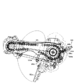
図4に示すように、フロート55,56との配置位置の関係でセンタフロート55の前方にあるセンタロータ27bは、サイドフロート56の前方にあるサイドロータ27aより前方に配置されている。そのため、センタロータ27bの駆動軸部70bへの動力は後輪11の後輪伝動ケース18内のギヤからロータ駆動ケース87内のギヤに伝動され、該ロータ駆動ケース87から自在継手(駆動シャフト)72等を介して伝達され、左右のロータ27a,27aの駆動軸部70aは左センタロータ27bの駆動軸部70bの車体内側の端部から動力が伝達されるチェーンケース73内のチェーン(図示せず)から動力伝達される。   As shown in FIG. 4, the center rotor 27 b in front of the center float 55 in relation to the arrangement position with the floats 55 and 56 is arranged in front of the side rotor 27 a in front of the side float 56. Therefore, power to the drive shaft portion 70b of the center rotor 27b is transmitted from the gear in the rear wheel transmission case 18 of the rear wheel 11 to the gear in the rotor drive case 87, and the universal joint (drive shaft) is transmitted from the rotor drive case 87. The drive shaft 70a of the left and right rotors 27a, 27a is transmitted through the chain 72 in the chain case 73 to which power is transmitted from the inner end of the drive shaft 70b of the left center rotor 27b (not shown). Power).

ロータ27bの駆動軸部70bは左右一対のチェーンケース73,73を介して支持されているだけなので、チェーンケース73,73の補強のために左右一対のチェーンケース73,73を橋渡しする補強部材74が設けられている。
また、図1に示すように、ロータ27a,27bの後ろ上方には、ロータカバー37を設け、フロート55,56上に泥がかからないようにしている。
Since the drive shaft portion 70b of the rotor 27b is only supported through a pair of left and right chain cases 73, 73, a reinforcing member 74 that bridges the pair of left and right chain cases 73, 73 to reinforce the chain cases 73, 73. Is provided.
As shown in FIG. 1, a rotor cover 37 is provided on the upper rear side of the rotors 27 a and 27 b so that mud is not applied to the floats 55 and 56.

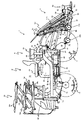
また、図5の側面図に苗植付部4が圃場に接地した状態での苗タンク51とロータ27a,27bなどを示し、図6に苗タンク51を上昇させる途中の側面図、図7に苗タンク51の最上げ時の側面図を示す。また図8には図6の一部拡大図を示す。
整地装置27(27a,27b)の上下位置を変更する苗植付部4に左右一対設けられた整地ロータ上下動機構Rとして、上下動モータに83と扇形ギヤ85と上下動アーム86と、扇形ギヤ85の回動に伴う角度の変化を検出するポテンショメータ80を設ける。該ポテンショメータ80には、ポテンショアーム80aが上下回動自在に設けられており、該ポテンショアーム80aには、後述する回動軸89に基部を装着した連動ピン80bの端部が装着されている。これにより、回動軸89が回動すると、連動ピン80bがポテンショアーム80aを上昇または下降させ、ポテンショアーム80aの回動角度をポテンショメータ80が検出するものとする。
5 shows the seedling tank 51 and the rotors 27a and 27b in a state where the seedling planting portion 4 is in contact with the field, and FIG. 6 is a side view in the middle of raising the seedling tank 51 and FIG. The side view at the time of the highest raising of the seedling tank 51 is shown. 8 shows a partially enlarged view of FIG.
As the leveling rotor vertical movement mechanism R provided on the seedling planting part 4 for changing the vertical position of the leveling device 27 (27a, 27b), a vertical movement motor 83, a sector gear 85, a vertical movement arm 86, and a sector shape are provided. A potentiometer 80 is provided for detecting a change in angle with the rotation of the gear 85. The potentiometer 80 is provided with a potentiometer arm 80a that can be pivoted up and down. The potentiometer arm 80a is fitted with an end of an interlocking pin 80b having a base attached to a pivot shaft 89 to be described later. Thus, when the rotation shaft 89 rotates, the interlocking pin 80b raises or lowers the potentiometer arm 80a, and the potentiometer 80 detects the rotation angle of the potentiometer arm 80a.

上下動モータ83の回動軸83a(図8)の回動に連動するギヤ83aに噛合する扇形ギヤ85を回動させると、上下動アーム86が回動軸89(苗タンク51の両側壁に支持される)と同軸上に設けられた上下動アーム86の回動軸89を中心に動いて、上下動アーム86に支持された退避回動アーム90(図10参照)の先端に回動自在に設けたロータ持上げロッド91を上げ下げする。上下動アーム86の回動軸89の長手方向は左右方向に向いている。また、左右のサイドロータ27aに設ける前記ロータカバー37に、前記ロータ持上げロッド91の他端部を連結している。   When the fan-shaped gear 85 meshing with the gear 83a interlocking with the rotation of the rotation shaft 83a (FIG. 8) of the vertical movement motor 83 is rotated, the vertical movement arm 86 is moved to the rotation shaft 89 (on both side walls of the seedling tank 51). Is supported on the shaft 89 of the vertically moving arm 86 provided on the same axis as the center, and is pivotable to the tip of the retractable rotating arm 90 (see FIG. 10) supported by the vertically moving arm 86. The rotor lifting rod 91 provided on is raised and lowered. The longitudinal direction of the rotation shaft 89 of the vertical movement arm 86 is directed in the left-right direction. The other end of the rotor lifting rod 91 is connected to the rotor cover 37 provided on the left and right side rotors 27a.

苗タンク51を上昇操作すると、整地ロータ上下動機構Rが作動してロータ持上げロッド91の上昇に伴って左右のサイドロータ27a,27aが上昇する。その際、センタロータ27bは前下がりとなり、整地装置27全体は前下がり状態で圃場上に宙づり状態となる。センタロータ27bの重量で整地装置27が前下がり姿勢になると、整地装置27や昇降リンク機構3などに負荷がかかることを防止できるので、整地装置27や昇降リンク機構3などの破損が防止されると共に、構成部材の耐久性が向上する。   When the seedling tank 51 is raised, the leveling rotor vertical movement mechanism R is activated, and the left and right side rotors 27a and 27a are raised as the rotor lifting rod 91 is raised. At that time, the center rotor 27b is lowered forward, and the entire leveling device 27 is suspended from the field in the forward lowered state. When the leveling device 27 is in the forwardly lowered posture due to the weight of the center rotor 27b, it is possible to prevent a load from being applied to the leveling device 27, the lifting link mechanism 3, and the like, so that damage to the leveling device 27, the lifting link mechanism 3, etc. is prevented. At the same time, the durability of the constituent members is improved.

なお、中央整地ロータ27bの後部の取付アーム92と退避回動アーム90に形成した取付孔の間に、吊下げスプリング78が退避回動アーム90に形成した取付孔に係止されており、整地装置27が前下がり姿勢のまま上昇すると、中央整地ロータ27bの後部の取付アーム92に設けられた吊下げスプリング78の取付孔がスプリング78に過度に引っ張られるため、長期の使用により取付孔が削られて径が大きくなると、吊下げスプリング78が十分な吊下げ作用を発揮できなくなり、自重で前傾した中央整地ロータ27bが土中に入り込み、接触抵抗で破損するおそれがある。   A suspension spring 78 is locked in the mounting hole formed in the retracting rotation arm 90 between the mounting arm 92 at the rear of the central leveling rotor 27b and the mounting hole formed in the retracting rotation arm 90. When the device 27 is lifted in the forwardly lowered posture, the attachment hole of the suspension spring 78 provided in the attachment arm 92 at the rear part of the central leveling rotor 27b is excessively pulled by the spring 78, so that the attachment hole is cut by long-term use. If the diameter is increased, the suspension spring 78 cannot exhibit a sufficient suspension action, and the central leveling rotor 27b tilted forward by its own weight may enter the soil and break due to contact resistance.

また、中央整地ロータ27bが前傾し始める高さまで苗植付部4を上昇させると、上下動モータ83を作動させて扇形ギヤ85を回転させるとともに、上下動アーム86を回動させて中央整地ロータ27bを下方に移動させて前傾量を小さくする構成としたことにより、吊下げスプリング78が、吊下げスプリング78の最上げ時の長さ(406mm)以上には伸びなくなるので、吊下げスプリング78の強度を過度に強くする必要が無く、吊下げスプリング78のコストダウンが図れる。   Further, when the seedling planting portion 4 is raised to a height at which the center leveling rotor 27b begins to tilt forward, the vertical movement motor 83 is operated to rotate the sector gear 85 and the vertical movement arm 86 is rotated to rotate the central leveling. Since the rotor 27b is moved downward to reduce the amount of forward tilt, the suspension spring 78 does not extend beyond the maximum length (406 mm) of the suspension spring 78, so that the suspension spring It is not necessary to increase the strength of 78 excessively, and the cost of the suspension spring 78 can be reduced.

また、中央整地ロータ27bの吊下げスプリング78の取付部材がスプリング78に過度に引っ張られるため、引掛け孔が広がりやすく、スプリング78の吊下げ作用力が低下するおそれがある。また、整地装置27が上昇し過ぎてロワーリンク41に接触することを防止すべく、このスプリング78の取付部材にロワーリンク41に接触するカムローラ77を設けている。このカムローラ77は回転可能であり、苗タンク51の上昇の際にロワーリンク41の下面に沿って回転して整地装置27の上昇を防止するが、接触抵抗による負荷が累積すると、カムローラ77の回動軸77aやロワーリンク41が変形するおそれがある。
しかし、本発明により、作業者が手動で整地装置27を下降させる必要が無く、作業能率が向上する。
Further, since the attachment member of the suspension spring 78 of the central leveling rotor 27b is excessively pulled by the spring 78, the hooking hole is likely to expand, and the suspension acting force of the spring 78 may be reduced. Further, in order to prevent the leveling device 27 from rising too much and coming into contact with the lower link 41, a cam roller 77 that contacts the lower link 41 is provided on the mounting member of the spring 78. The cam roller 77 is rotatable and rotates along the lower surface of the lower link 41 when the seedling tank 51 is raised to prevent the leveling device 27 from rising. However, when a load due to contact resistance accumulates, the cam roller 77 rotates. The moving shaft 77a and the lower link 41 may be deformed.
However, according to the present invention, there is no need for the operator to manually lower the leveling device 27, and the work efficiency is improved.

また、整地装置27が上昇し過ぎてロワーリンク41に接触することを防止するために、このスプリング78の取付アーム92にロワーリンク41に接触するカムローラ77を設けている。このカムローラ77は回転可能であり、苗タンク51の上昇の際にロワーリンク41の下面に沿って回転して整地装置27の上昇を防止する。こうして、作業者が手動で整地装置27を下降させる必要が無く、作業能率が従来技術より向上する。   Further, in order to prevent the leveling device 27 from rising too much and coming into contact with the lower link 41, a cam roller 77 that comes into contact with the lower link 41 is provided on the mounting arm 92 of the spring 78. The cam roller 77 is rotatable and rotates along the lower surface of the lower link 41 when the seedling tank 51 is raised to prevent the leveling device 27 from rising. Thus, there is no need for the operator to manually lower the leveling device 27, and the work efficiency is improved as compared with the prior art.

昇降リンク機構3に現在の昇降位置を検知する昇降リンクセンサ94を設け、該昇降リンクセンサ94による昇降リンク機構3の昇降時の検知角度から苗タンク51の上下位置が検知できる。そして苗タンク51の上下位置が所定位置(例:地表50cm付近)に下降したと制御装置100が判断すると、整地ロータ上下動装置Rの整地ロータ上下動モータ83を作動させて整地装置27を圃場に下降させる。   A lift link sensor 94 that detects the current lift position is provided in the lift link mechanism 3, and the vertical position of the seedling tank 51 can be detected from the detection angle when the lift link mechanism 3 is lifted by the lift link sensor 94. When the control device 100 determines that the vertical position of the seedling tank 51 has been lowered to a predetermined position (eg, about 50 cm above the ground surface), the leveling rotor vertical movement motor 83 of the leveling rotor vertical movement device R is operated to move the leveling device 27 to the field. To lower.

整地装置27の下降移動距離が苗タンク51や植付装置52の下降移動距離よりも長くなると、整地装置27が土中に入り込み、損傷するおそれがある。しかし、苗タンク51を下降させ、所定位置まで下降した段階で整地ロータ上下動装置Rを作動させて整地装置27を下降させることにより、整地装置27の下降移動距離が苗タンク51や植付装置52の下降移動距離よりも長くなることがなくなり、整地装置27が土中に入り込まなくなるため、整地装置27が圃場面を荒らすことが防止される。   If the moving distance of the leveling device 27 is longer than the moving distance of the seedling tank 51 and the planting device 52, the leveling device 27 may enter the soil and be damaged. However, when the seedling tank 51 is lowered, and the leveling rotor vertical movement device R is operated to lower the leveling device 27 when the seedling tank 51 is lowered to a predetermined position, the downward movement distance of the leveling device 27 is changed to the seedling tank 51 and the planting device. 52, the leveling device 27 is prevented from entering the soil, and the leveling device 27 is prevented from roughing the field scene.

左右のサイドロータ27aに、整地装置27全体を持ち上げるためのロータ持上げロッド91の下部を連結し、左右のロータ持上げロッド91,91の上部に左右の退避回動アーム90の先端が連結し、左右のロータ上下動アーム86,86の一端部を苗タンク51に支持された回動軸89に装着し、左右のサイドロータ27a,27aのうちの一方のサイドロータ27a側に扇形ギヤ85とロータ上下動モータ83や整地ロータ上下動ポテンショメータ80を配置している。図11に一方のサイドロータ27a側にのみの部分平面を示す。   The lower side of the rotor lifting rod 91 for lifting the entire leveling device 27 is connected to the left and right side rotors 27a, and the tips of the left and right revolving pivot arms 90 are connected to the upper parts of the left and right rotor lifting rods 91, 91. One end of each of the rotor vertical movement arms 86, 86 is attached to a rotation shaft 89 supported by the seedling tank 51, and the sector gear 85 and the vertical movement of the rotor are arranged on one side rotor 27 a side of the left and right side rotors 27 a, 27 a. A dynamic motor 83 and a leveling rotor vertical movement potentiometer 80 are arranged. FIG. 11 shows a partial plane only on one side rotor 27a side.

整地ロータ上下動機構Rを構成する扇形ギヤ85とロータ上下動モータ83を、駆動シャフト72が駆動力を供給するセンタロータ27b側に設けたことにより、駆動部品が一方に集中するため、メンテナンス時に作業を集中的に行うことができる。
また左右のロータ上下動アーム86,86を一つの回動軸89に装着したことにより、扇形ギヤ85とロータ上下動モータ83を左右どちらか一方のロータ27a側に配置すればよいため、構成部品が減少し、メンテナンス性の向上や機体の軽量化が図られる。
Since the fan-shaped gear 85 and the rotor vertical movement motor 83 constituting the leveling rotor vertical movement mechanism R are provided on the center rotor 27b side where the driving shaft 72 supplies the driving force, the driving components are concentrated on one side. Work can be done intensively.
Further, since the left and right rotor vertical movement arms 86, 86 are mounted on one rotating shaft 89, the fan-shaped gear 85 and the rotor vertical movement motor 83 may be disposed on either the left or right rotor 27a side. This will reduce maintenance and improve the weight of the aircraft.

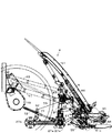
図9の要部側面図に示すように、ロータ上下動アーム86,86とロータ持上げロッド91,91の間に退避回動アーム90,90を設け、該退避回動アーム90,90をロータ上下動アーム86,86とロータ持上げロッド91,91にそれぞれ設けた回動支点90a,90a;90b,90bとを中心に上下回動自在に装着して、退避回動アーム90,90は正面視L字形に形成し、ロータ上下動アーム86,86の一側面と上方を覆う形状とした。
図10に図9の矢印A方向から見た構成の一部の矢視図で示すように、ロータ上下動アーム86,86の一側面と上方を覆う配置で退避回動アーム90を設け、このロータ上下動アーム86,86とロータ持上げロッド91,91の間に退避回動アーム90,90を設けたことにより、整地装置27が段差や石などに乗り上げて大きく上昇しても、退避回動アーム90,90が回動支点90b,90b;90a,90aを中心に上下回動するので、ロータ上下動アーム86,86は回動軸89,89を中心に下方回動するだけで、整地装置27を上方移動させることができるので、ロータ上下動アーム86,86や回動軸89,89や扇形ギヤ85が負荷により破損することが防止され、耐久性が向上する。
As shown in the side view of the main part of FIG. 9, retraction rotation arms 90, 90 are provided between the rotor vertical movement arms 86, 86 and the rotor lifting rods 91, 91, and the retraction rotation arms 90, 90 are moved up and down the rotor. The revolving and turning arms 90 and 90 are viewed from the front L. The moving arms 86 and 86 and the turning fulcrums 90a and 90a; 90b and 90b provided on the rotor lifting rods 91 and 91, respectively. It was formed in a letter shape and covered with one side and the upper side of the rotor vertical movement arms 86, 86.
As shown in FIG. 10 as a partial arrow view of the configuration viewed from the direction of arrow A in FIG. 9, a retraction rotation arm 90 is provided so as to cover one side and the upper side of the rotor vertical movement arms 86, 86. By providing the retraction rotation arms 90, 90 between the rotor vertical movement arms 86, 86 and the rotor lifting rods 91, 91, even if the leveling device 27 rides on a step or a stone and rises greatly, the retraction rotation Since the arms 90 and 90 rotate up and down around the rotation fulcrums 90b and 90b; 90a and 90a, the rotor vertical movement arms 86 and 86 only rotate downward about the rotation shafts 89 and 89, so that the leveling device 27 can be moved upward, the rotor vertical movement arms 86 and 86, the rotary shafts 89 and 89, and the sector gear 85 are prevented from being damaged by a load, and the durability is improved.

このように、整地ロータ上下動機構Rを作動させたときは、退避回動アーム90はロータ上下動アーム86の上下回動に連動して上下回動するため、整地装置27の上下位置調節を円滑に行うことができる。   As described above, when the leveling rotor vertical movement mechanism R is operated, the retraction rotation arm 90 is rotated up and down in conjunction with the vertical rotation of the rotor vertical movement arm 86, so that the vertical position adjustment of the leveling device 27 is performed. It can be done smoothly.

図5に示すように苗タンク51の下部(実際は、植付装置52の植付伝動ケース95の下部に設けたポテンショメータ)に圃場の凹凸に追従して上下回動する接触検知プレート96と、接触検知プレート96をサイドロータ27aの非整地位置(ロータを構成する回転体のうち、意図的に間隔を空けてあり、その部分ことを言う)を通して圃場面に先端部を接触させ、接触検知プレート96の基部に取り付けた該接触検知プレート96の上下回動量を検出するポテンショメータ81(例えば15〜30度を検知すると信号発信)を設け、該ポテンショメータ81が前記所定角度の信号を発信すると、制御装置100の指令に基づき昇降油圧シリンダ46が苗タンク51を自動的に、例えば10〜20cm程度上昇させる。   As shown in FIG. 5, a contact detection plate 96 that rotates up and down following the unevenness of the field is contacted with the lower part of the seedling tank 51 (actually, a potentiometer provided at the lower part of the planting transmission case 95 of the planting device 52). The tip of the detection plate 96 is brought into contact with the field through the non-leveling position of the side rotor 27a (the part of the rotor constituting the rotor is intentionally spaced, which is said to be a part thereof). A potentiometer 81 (for example, a signal is transmitted when 15 to 30 degrees is detected) is provided for detecting the amount of vertical rotation of the contact detection plate 96 attached to the base of the controller. When the potentiometer 81 transmits a signal of the predetermined angle, the control device 100 The lifting hydraulic cylinder 46 automatically raises the seedling tank 51 by, for example, about 10 to 20 cm.

圃場に落ちている石やゴミ(空き缶など金属)を接触検知プレート96が上下回動量から検知すると、苗タンク51が所定高さ上昇することにより、整地装置27が石やゴミと接触して過負荷が掛かることを防止できるので、整地装置27や整地ロータ上下動機構Rが破損することが防止される。これにより、整地装置27が石やゴミと接触して過負荷が掛かることが防止され、整地ロータ上下動機構Rにも大きな負荷がかからない。また、石は形状によってはロータ27a,27bの回転を著しく妨げ、破損させる可能性があるが、そのようなロータ27a,27bの破損のおそれがない。   When the contact detection plate 96 detects a stone or dust (metal such as an empty can) falling on the field, the seedling tank 51 rises by a predetermined height, so that the ground leveling device 27 comes into contact with the stone or dust. Since a load can be prevented, the leveling device 27 and the leveling rotor vertical movement mechanism R are prevented from being damaged. Thereby, it is prevented that the leveling device 27 comes into contact with stones and dust and is overloaded, and the leveling rotor vertical movement mechanism R is not subjected to a large load. Further, depending on the shape of the stone, the rotation of the rotors 27a and 27b may be significantly hindered and damaged, but there is no risk of such damage to the rotors 27a and 27b.

また、接触検知プレート96は多少の圃場面の凹凸は無視するため、圃場面に細かい凹凸があるたびに苗タンク51が上下動することを防止できるので、植付装置52が圃場面から離れて苗を植え付け損なう事が防止される。   Further, since the contact detection plate 96 ignores some unevenness of the farm scene, it can prevent the seedling tank 51 from moving up and down every time there is a fine unevenness in the farm scene, so that the planting device 52 moves away from the farm scene. Failure to plant seedlings is prevented.

ロータ27a,27aは、連結部材71で伝動ケース50に支持されるのが一般的であるが、図4の苗植付部4の要部平面図に示すように、より耐久性のあるロータ27a,27bの支持のために、連結部材71をチェーンケース73の部分に連結する構成としても良い。こうして、連結部材71が重量のあるチェーンケース73の位置で整地装置27を支持することになるため、連結部材71によるロータ27a,27bの支持でより強度が増大し、耐久性が向上する。   The rotors 27a and 27a are generally supported by the transmission case 50 by the connecting member 71. However, as shown in the plan view of the main part of the seedling planting part 4 in FIG. , 27b, the connecting member 71 may be connected to the chain case 73 portion. Thus, since the connecting member 71 supports the leveling device 27 at the position of the heavy chain case 73, the strength is increased and the durability is improved by the support of the rotors 27a and 27b by the connecting member 71.

図12の植付伝動ケース95内の一部側面図に示すように、植付爪52aに動力を伝達するギヤを回動させる植付伝動チェーン95aを外側から常時押圧しているアジャスタ98を設けている。該アジャスタ98は植付伝動チェーン95aに対して垂直方向から押圧する軸部98aを備え、該軸部98aにはスプリング98bが設けられ、該スプリング98bを軸部98aの外側から押圧するカバー98cと、該カバー98cの外側に設けたボルト98dが配置されているので、ボルト98dでカバー98cを軸部98aで押圧する位置を調整することで、植付伝動チェーン95aが植付爪52aに動力を伝達するスプロケット95b方向に押圧され、植付爪52aを作動するスプロケット95bに負荷をかけることができる。この負荷を大きくすると苗の植付間隔を通常より大きくすることができ、いわゆる、苗の疎植ができる。
この苗の疎植をしないときはアジャスタ98を緩めて通常の苗の植付間隔が得られるように植付爪52aに動力を伝達するギヤを回動させる。
As shown in a partial side view in the planting transmission case 95 of FIG. 12, an adjuster 98 is provided to constantly press the planting transmission chain 95a for rotating the gear for transmitting power to the planting claw 52a from the outside. ing. The adjuster 98 includes a shaft portion 98a that presses against the planting transmission chain 95a from the vertical direction. The shaft portion 98a is provided with a spring 98b, and a cover 98c that presses the spring 98b from the outside of the shaft portion 98a; Since the bolt 98d provided on the outside of the cover 98c is disposed, the planting transmission chain 95a powers the planting claw 52a by adjusting the position at which the cover 98c is pressed by the shaft portion 98a with the bolt 98d. A load can be applied to the sprocket 95b that is pressed in the direction of the transmitting sprocket 95b and operates the planting claw 52a. When this load is increased, the seedling planting interval can be made larger than usual, and so-called seedling sparse planting can be achieved.
When the seedling is not sparsely planted, the adjuster 98 is loosened and the gear for transmitting power to the planting claw 52a is rotated so that a normal seedling planting interval is obtained.

図13のフロート55,56の支持構造の斜視図に示すように、4〜5枚のフロート55,56を備えた苗植付部4のサイドフロート56の圃場面に対する高さを、センタフロート55のそれより高く出来る構成にして、サイドフロート56がセンタフロート55側の圃場に植え付けた苗を潰さないようにした。   As shown in the perspective view of the support structure of the floats 55 and 56 in FIG. 13, the height of the side float 56 of the seedling planting part 4 having 4 to 5 floats 55 and 56 with respect to the field scene is determined as the center float 55. The side float 56 prevents the seedlings planted in the field on the center float 55 side from being crushed.

サイドフロート56の圃場面に対する高さをセンタフロート55のそれより高くするためには、センタフロート55の左右方向に共通して設けた円筒状の植付深さフレーム88bを設け、サイドフロート56の筒状の植付深さフレーム88aの左側に、前記円筒状の植付深さフレーム88bに挿入可能な太さの棒状の植付深さフレーム88cを溶接しておき、左サイドフロート56もセンタフロート55と同じ内径の円筒状の植付深さフレーム88aを設けている。そして、サイドフロートの棒状の植付深さフレーム88cを、センタフロート55の左右方向に設けた円筒状の植付深さフレーム88bと左サイドフロート56の円筒状の植付深さフレーム88aに差し込んで固定する。   In order to make the height of the side float 56 relative to the field scene higher than that of the center float 55, a cylindrical planting depth frame 88b provided in common in the left and right direction of the center float 55 is provided. A rod-like planting depth frame 88c having a thickness that can be inserted into the cylindrical planting depth frame 88b is welded to the left side of the cylindrical planting depth frame 88a, and the left side float 56 is also centered. A cylindrical planting depth frame 88a having the same inner diameter as the float 55 is provided. Then, the rod-like planting depth frame 88c of the side float is inserted into the cylindrical planting depth frame 88b provided in the left-right direction of the center float 55 and the cylindrical planting depth frame 88a of the left side float 56. Secure with.

右のサイドフロート56に固定した棒状の植付深さフレーム88aに固定したアーム88dと補助レバー93の間にケーブル93aを設け、該補助レバー93aを操作することで、センタフロート55の植付深さフレーム88bを中心軸としてサイドフロート56を回動可能にしている。
従って、補助レバー93を操作してセンタフロート55の植付深さフレーム88aを中心にサイドフロート56を回動させて、センタフロート55側の圃場に植え付けた苗を潰さないようにすることができる。
A cable 93a is provided between the arm 88d fixed to the rod-shaped planting depth frame 88a fixed to the right side float 56 and the auxiliary lever 93, and the auxiliary lever 93a is operated, whereby the planting depth of the center float 55 is increased. The side float 56 is rotatable about the frame 88b as a central axis.
Therefore, by operating the auxiliary lever 93 and rotating the side float 56 around the planting depth frame 88a of the center float 55, it is possible to prevent the seedling planted in the field on the center float 55 side from being crushed. .

図14(a)には苗タンク51の背面図を示し、6条植の2条単位で1つの送りベルト駆動モータ96を設けている。畦クラッチレバー14を操作して畦クラッチを切りにした条は苗送り量で10mmで逆転し、再び畦クラッチを入りにすると10mm送り、元の位置に戻る。   FIG. 14 (a) shows a rear view of the seedling tank 51, and one feed belt drive motor 96 is provided for each two-row unit of six-row planting. The barb with the barb clutch disengaged by operating the barb clutch lever 14 reverses the seedling feed amount by 10 mm. When the barb clutch is engaged again, the barb is turned 10 mm and returned to its original position.

従来は図14(b)に示すように、畦クラッチを切にすると、苗が前板51cと接触したまま動かないので、苗の先端が前板51cの形状に沿って曲がり、植付爪52aの回転軌跡から離間してしまう。この状態では、植付爪52aが苗を掴むことができず、欠株が多発してしまう。
しかしながら、上記手順にて作業をすることにより、畦クラッチを切操作すると苗が前板51cから退避するので、苗が曲がって植付爪52aから離間した姿勢となることが防止される。これにより、植付爪52aで確実に苗を掴み、圃場に確実に苗を植え付けることができるので、作業者が欠株となった箇所に手作業で苗を植え付ける作業が不要となり、作業能率が向上すると共に、作業者の労力が軽減される。
Conventionally, as shown in FIG. 14 (b), when the hook clutch is disengaged, the seedling does not move while in contact with the front plate 51c, so the tip of the seedling bends along the shape of the front plate 51c, and the planting claw 52a It will be away from the rotation trajectory. In this state, the planting claws 52a cannot grasp the seedlings, resulting in frequent missing stocks.
However, by performing the above procedure, the seedling is retracted from the front plate 51c when the hook clutch is turned off, so that the seedling is prevented from being bent and separated from the planting claw 52a. As a result, the seedling can be securely grasped by the planting claws 52a and the seedling can be reliably planted in the field, so that the work of manually planting the seedling in the place where the worker has become a strain becomes unnecessary, and the work efficiency is improved. As well as improving, the labor of the operator is reduced.

本発明は田植機の苗植付部を簡易な構成とすることができて利用可能性が大きい。   In the present invention, the seedling planting part of the rice transplanter can be configured simply and has a high possibility of use.

1 施肥装置付き乗用型田植機 2 走行車体
3 昇降リンク装置 4 苗植付部
5 粉粒体繰出し装置(施肥装置) 8 切替スイッチ
10 前輪 11 後輪
11a 後輪駆動軸 12 ミッションケース
13 前輪ファイナルケース 15 メインフレーム
16 変速レバー 18 後輪伝動ケース
20 エンジン 21 ベルト伝動装置
23 HST 25 植付クラッチケース
26 植付伝動軸 27(27a,27b) ロータ
28 施肥伝動機構 30 エンジンカバー
31 座席 32 フロントカバー
33 操縦部 34 ハンドル
35 フロアステップ 36 リヤステップ
37 ロータカバー 38 予備苗載台
40 上リンク 41 下リンク
42 リンクベースフレーム 43 縦リンク
44 連結軸 46 昇降油圧シリンダ
49 支持機枠 50 伝動ケース
51 苗タンク(苗載台) 51a 苗取出口
51b 苗送りベルト 51c 前板
52 苗植付装置 52a 苗植付具(植付爪)
53 ブロア用電動モータ 55 センタフロート
56 サイドフロート 58 ブロア
59 エアチャンバ 60 肥料ホッパ
61 繰出部 62 施肥ホース
63 ロータ昇降用モータ 65 苗植付部支持枠体
65a 支持ローラ 65b 両側辺部材
69 作溝体 70(70a,70b) 駆動軸部
71 連結部材 72 自在継手(伝動シャフト)
73 チェーンケース 74 補強部材
77 カムローラ 77a 回動軸
78 吊下げスプリング
80 扇形ギヤ回動角度検知用ポテンショメータ
81 接触検知プレート作動量検知用ポテンショメータ
83 整地ロータ上下動モータ 85 扇形ギヤ
86 上下動アーム 87 ロータ駆動ケース
88a,88b,88c 植付深さフレーム
88d 植付深さフレームのアーム 89 回動軸
90 退避回動アーム 91 ロータ持上げロッド
92 取付アーム 93 補助レバー
94 昇降リンクセンサ 95 植付伝動ケース
95a 植付伝動チェーン 95b スプロケット
96 接触検知プレート 97 クラッチシフター
98 アジャスタ 98a 軸部
98b スプリング 98c カバー
98d ボルト 99 クラッチケーブル
100 制御装置 R 整地ロータ上下動機構
DESCRIPTION OF SYMBOLS 1 Riding type rice transplanter with fertilizer 2 Traveling vehicle body 3 Elevating link device 4 Seedling planting part 5 Granule feeding device (fertilizer) 8 Changeover switch 10 Front wheel 11 Rear wheel 11a Rear wheel drive shaft 12 Mission case 13 Front wheel final case 15 Main frame 16 Shift lever 18 Rear wheel transmission case 20 Engine 21 Belt transmission device 23 HST 25 Planting clutch case 26 Planting transmission shaft 27 (27a, 27b) Rotor 28 Fertilizer transmission mechanism 30 Engine cover 31 Seat 32 Front cover 33 Steering Part 34 Handle 35 Floor step 36 Rear step 37 Rotor cover 38 Spare seedling stage 40 Upper link 41 Lower link 42 Link base frame 43 Vertical link 44 Connecting shaft 46 Lifting hydraulic cylinder 49 Supporting machine frame 50 Transmission case 51 Seedling tank (seedling stage) Stand) 51a Outlet 51b seedling feeding belt 51c front plate 52 seedling planting apparatus 52a seedling planting device (planting claw)
53 Electric motor for blower 55 Center float 56 Side float 58 Blower 59 Air chamber 60 Fertilizer hopper 61 Feeding part 62 Fertilization hose 63 Motor for raising and lowering the rotor 65 Seedling planting part support frame body 65a Support roller 65b Both side members 69 Groove body 70 (70a, 70b) Drive shaft portion 71 Connecting member 72 Universal joint (transmission shaft)
73 Chain case 74 Reinforcement member 77 Cam roller 77a Rotating shaft 78 Suspension spring 80 Fan-shaped gear rotation angle detection potentiometer 81 Contact detection plate actuation amount detection potentiometer 83 Leveling rotor vertical motion motor 85 Fan-shaped gear 86 Vertical motion arm 87 Rotor drive Case 88a, 88b, 88c Planting depth frame 88d Arm of planting depth frame 89 Rotating shaft 90 Retracting and rotating arm 91 Rotor lifting rod 92 Mounting arm 93 Auxiliary lever 94 Lifting link sensor 95 Planting transmission case 95a Planting Transmission chain 95b Sprocket 96 Contact detection plate 97 Clutch shifter 98 Adjuster 98a Shaft 98b Spring 98c Cover 98d Bolt 99 Clutch cable 100 Controller R Leveling rotor vertical movement mechanism

Claims (5)

圃場を走行する走行車体(2)と、エンジン(20)と、該エンジン(20)からの駆動力を変速する変速装置を収納したミッションケース(12)と、該ミッションケース(12)からの駆動力を左右の後輪(11)に伝動する後輪伝動ケース(18)と、圃場面を均す中央整地ロータ(27b)と該中央整地ロータ(27b)の左右両側、且つ後側で圃場面を均す左右の側方整地ロータ(27a,27a)を一体的に設けた整地装置(27)と、後輪伝動ケース(18)からの駆動力を左右の側方整地装置(27a)の中のどちらか一側に伝動させるための駆動シャフト(27)と、走行車体(2)の後部に昇降リンク機構(3)と、該昇降リンク機構(3)の後部に苗を積載する複数条の苗タンク(51)と、各苗タンク(51)から苗を取って圃場に植え付ける複数条の植付装置(52)とを設けた苗移植機において、
前記左右の側方整地ロータ(27a)の中のいずれか一方に連結して、整地装置(27)全体の上下位置を変更する左右一対の整地ロータ上下動機構(R)を設けたことを特徴とする苗移植機。
A traveling vehicle body (2) traveling in the field, an engine (20), a transmission case (12) housing a transmission for shifting the driving force from the engine (20), and driving from the transmission case (12) A rear wheel transmission case (18) for transmitting force to the left and right rear wheels (11), a center leveling rotor (27b) for leveling the farm scene, and the left and right sides of the center leveling rotor (27b) and the rear scene Leveling device (27) integrally provided with right and left lateral leveling rotors (27a, 27a) and driving force from rear wheel transmission case (18) in the left and right side leveling devices (27a) A drive shaft (27) for transmission to one of the above, a lifting link mechanism (3) at the rear of the traveling vehicle body (2), and a plurality of strips for loading seedlings at the rear of the lifting link mechanism (3) From the seedling tank (51) and each seedling tank (51) In taking planting device plural rows planting in the field (52) and the provided seedlings transplanter,
A pair of left and right leveling rotor vertical movement mechanisms (R) that change the vertical position of the entire leveling device (27) are provided by being connected to one of the left and right side leveling rotors (27a). Seedling transplanter.
前記昇降リンク機構(3)に現在の昇降位置を検知する昇降位置検知部材(94)を設け、該昇降位置検知部材(94)による昇降リンク機構(3)の昇降時の検知角度から苗タンク(51)の上下位置を識別して、前記苗タンク(51)の上下位置が所定位置に下降すると、整地ロータ上下動装置(R)を作動させて整地装置(27)を圃場に下降させる制御を行う制御装置(100)を備えたことを特徴とする請求項1記載の苗移植機。   The lift link mechanism (3) is provided with a lift position detection member (94) for detecting the current lift position, and a seedling tank (from the detection angle when the lift link mechanism (3) is lifted by the lift position detection member (94) ( 51) When the vertical position of the seedling tank (51) is lowered to a predetermined position by identifying the vertical position of the seedling tank (51), the ground leveling rotor vertical movement device (R) is operated and the leveling device (27) is lowered to the field. The seedling transplanter according to claim 1, further comprising a control device (100) for performing the operation. 前記左右の側方整地装置(27a,27a)に整地装置(27)全体を持ち上げるためのロータ持上げロッド(91,91)の下部を連結し、
該左右のロータ持上げロッド(91,91)の上部に左右のロータ上下動アーム(86,86)の一端部側を連結し、
該左右のロータ上下動アーム(86,86)の一端部を苗タンク(51)に支持された回動軸(89)に装着し、
前記左右の側方整地ロータ(27a,27a)のうち、駆動シャフト(72)を設けた側方整地ロータ(27a)側に整地ロータ上下動装置(R)を構成する扇形ギヤ(85)とロータ上下動モータ(83)を配置することを特徴とする請求項2記載の苗移植機。
A lower part of a rotor lifting rod (91, 91) for lifting the entire leveling device (27) is connected to the left and right side leveling devices (27a, 27a),
One end of the left and right rotor vertical movement arms (86, 86) is connected to the upper part of the left and right rotor lifting rods (91, 91),
One end of the left and right rotor vertical movement arms (86, 86) is attached to a rotating shaft (89) supported by the seedling tank (51),
Of the left and right lateral leveling rotors (27a, 27a), a sector gear (85) and a rotor constituting the leveling rotor vertical movement device (R) on the side leveling rotor (27a) side provided with the drive shaft (72). The seedling transplanter according to claim 2, wherein a vertical movement motor (83) is arranged.
前記ロータ上下動アーム(86,86)とロータ持上げロッド(91,91)の間に退避回動アーム(90,90)を設け、該退避回動アーム(90,90)をロータ持上げロッド(91,91)に設けた回動支点(90a,90a)を中心に上下回動自在に装着し、
該退避回動アーム(90,90)は正面視L字形に形成し、ロータ上下動アーム(86,86)の一側面と上方を覆う形状としたことを特徴とする請求項2記載の苗移植機。
A retraction rotation arm (90, 90) is provided between the rotor vertical movement arm (86, 86) and the rotor lifting rod (91, 91), and the retraction rotation arm (90, 90) is connected to the rotor lifting rod (91). , 91) is mounted so as to be pivotable up and down around the pivot fulcrum (90a, 90a),
The seedling transplanter according to claim 2, wherein the revolving pivot arm (90, 90) is formed in an L shape when viewed from the front, and has a shape that covers one side and the upper side of the rotor vertical movement arm (86, 86). Machine.
苗タンク51の下部に圃場の凹凸に追従して上下回動する接触検知プレート(96)と、
該接触検知プレート(96)を側方整地ロータ(27a)の非整地位置を通して圃場面に先端部を接触させ、接触検知プレートの基部に取り付けた該接触検知プレート(96)の上下回動量を検出する接触検知プレートポテンショメータ(81)と、
該接触検知プレートポテンショメータ(81)で検出される接触検知プレート(96)の上下回動量が所定値になると、昇降油圧シリンダ(46)が苗タンク(51)を自動的に、所定量上昇させる制御構成を有する制御装置(100)を備えた請求項1記載の苗移植機。
A contact detection plate (96) that rotates up and down following the unevenness of the field in the lower part of the seedling tank 51;
The tip of the contact detection plate (96) is brought into contact with the farm scene through the non-leveling position of the side leveling rotor (27a), and the vertical rotation amount of the contact detection plate (96) attached to the base of the contact detection plate is detected. A contact detection plate potentiometer (81) to
When the vertical rotation amount of the contact detection plate (96) detected by the contact detection plate potentiometer (81) reaches a predetermined value, the lifting hydraulic cylinder (46) automatically raises the seedling tank (51) by a predetermined amount. The seedling transplanter according to claim 1, comprising a control device (100) having a configuration.
JP2012042616A 2012-02-29 2012-02-29 Seedling transplanter Active JP5957953B2 (en)

Priority Applications (1)

Application Number Priority Date Filing Date Title
JP2012042616A JP5957953B2 (en) 2012-02-29 2012-02-29 Seedling transplanter

Applications Claiming Priority (1)

Application Number Priority Date Filing Date Title
JP2012042616A JP5957953B2 (en) 2012-02-29 2012-02-29 Seedling transplanter

Publications (3)

Publication Number Publication Date
JP2013176331A true JP2013176331A (en) 2013-09-09
JP2013176331A5 JP2013176331A5 (en) 2015-05-14
JP5957953B2 JP5957953B2 (en) 2016-07-27

Family

ID=49268709

Family Applications (1)

Application Number Title Priority Date Filing Date
JP2012042616A Active JP5957953B2 (en) 2012-02-29 2012-02-29 Seedling transplanter

Country Status (1)

Country Link
JP (1) JP5957953B2 (en)

Cited By (2)

* Cited by examiner, † Cited by third party
Publication number Priority date Publication date Assignee Title
WO2017188313A1 (en) * 2016-04-28 2017-11-02 ヤンマー株式会社 Rice transplanter
CN110959354A (en) * 2018-09-28 2020-04-07 井关农机株式会社 Seedling transplanter

Citations (4)

* Cited by examiner, † Cited by third party
Publication number Priority date Publication date Assignee Title
JPH0731251A (en) * 1993-07-16 1995-02-03 Kubota Corp Combine harvester
JP2003289701A (en) * 2002-04-04 2003-10-14 Matsuyama Plow Mfg Co Ltd Agricultural implement working machine with marker
JP2006296244A (en) * 2005-04-18 2006-11-02 Matsuyama Plow Mfg Co Ltd Farm machine
JP2011244718A (en) * 2010-05-25 2011-12-08 Iseki & Co Ltd Work machine

Patent Citations (4)

* Cited by examiner, † Cited by third party
Publication number Priority date Publication date Assignee Title
JPH0731251A (en) * 1993-07-16 1995-02-03 Kubota Corp Combine harvester
JP2003289701A (en) * 2002-04-04 2003-10-14 Matsuyama Plow Mfg Co Ltd Agricultural implement working machine with marker
JP2006296244A (en) * 2005-04-18 2006-11-02 Matsuyama Plow Mfg Co Ltd Farm machine
JP2011244718A (en) * 2010-05-25 2011-12-08 Iseki & Co Ltd Work machine

Cited By (3)

* Cited by examiner, † Cited by third party
Publication number Priority date Publication date Assignee Title
WO2017188313A1 (en) * 2016-04-28 2017-11-02 ヤンマー株式会社 Rice transplanter
JP2017195840A (en) * 2016-04-28 2017-11-02 ヤンマー株式会社 Rice planting machine
CN110959354A (en) * 2018-09-28 2020-04-07 井关农机株式会社 Seedling transplanter

Also Published As

Publication number Publication date
JP5957953B2 (en) 2016-07-27

Similar Documents

Publication Publication Date Title
JP5045654B2 (en) Ride type rice transplanter
JP5957953B2 (en) Seedling transplanter
JP2014121280A (en) Seedling transplanter
JP5954468B2 (en) Ride type rice transplanter
JP5505023B2 (en) Seedling transplanter
JP6380599B2 (en) Seedling transplanter
JP2011045280A (en) Seedling transplanter
JP5761298B2 (en) Seedling transplanter
JP2008253231A (en) Traveling vehicle body
JP2006211995A (en) Seedling transplanter
JP2006211995A5 (en)
JP2011244733A (en) Seedling transplanter
JP5439731B2 (en) Paddy field machine
JP4998223B2 (en) Seedling transplanter
JP5641096B2 (en) Seedling transplanter
JP2008301761A (en) Rolling device of working car body
JP5136150B2 (en) Seedling planting machine
JP2014007997A (en) Seedling transplanter
JP6128078B2 (en) Seedling transplanter
JP4775106B2 (en) Seedling transplanter
JP5391859B2 (en) Working machine
JP5532694B2 (en) Seedling transplanter
JP5136464B2 (en) Seedling planting machine
JP5590017B2 (en) Ride type rice transplanter
JP2014103918A (en) Seedling transplanter

Legal Events

Date Code Title Description
A621 Written request for application examination

Free format text: JAPANESE INTERMEDIATE CODE: A621

Effective date: 20150224

A521 Written amendment

Free format text: JAPANESE INTERMEDIATE CODE: A523

Effective date: 20150330

A977 Report on retrieval

Free format text: JAPANESE INTERMEDIATE CODE: A971007

Effective date: 20151112

A131 Notification of reasons for refusal

Free format text: JAPANESE INTERMEDIATE CODE: A131

Effective date: 20151201

A521 Written amendment

Free format text: JAPANESE INTERMEDIATE CODE: A523

Effective date: 20160119

TRDD Decision of grant or rejection written
A01 Written decision to grant a patent or to grant a registration (utility model)

Free format text: JAPANESE INTERMEDIATE CODE: A01

Effective date: 20160524

A61 First payment of annual fees (during grant procedure)

Free format text: JAPANESE INTERMEDIATE CODE: A61

Effective date: 20160606

R150 Certificate of patent or registration of utility model

Ref document number: 5957953

Country of ref document: JP

Free format text: JAPANESE INTERMEDIATE CODE: R150