JP2013174385A - Air conditioner system, and remote controller - Google Patents
Air conditioner system, and remote controller Download PDFInfo
- Publication number
- JP2013174385A JP2013174385A JP2012038854A JP2012038854A JP2013174385A JP 2013174385 A JP2013174385 A JP 2013174385A JP 2012038854 A JP2012038854 A JP 2012038854A JP 2012038854 A JP2012038854 A JP 2012038854A JP 2013174385 A JP2013174385 A JP 2013174385A
- Authority
- JP
- Japan
- Prior art keywords
- information
- abnormal
- indoor unit
- unit
- remote controller
- Prior art date
- Legal status (The legal status is an assumption and is not a legal conclusion. Google has not performed a legal analysis and makes no representation as to the accuracy of the status listed.)
- Pending
Links
Images


Abstract
Description
本発明は、空気調和機システムに関する。 The present invention relates to an air conditioner system.
従来、空気調和機システムでは、室内機等からリモコンへ送信する情報として、検出した異常を伝達している。室内機等における異常を受信したリモコンでは、リモコンに備わる異常表示機能によって、受信した異常内容を表示する。このような技術が、下記特許文献1〜4において開示されている。 Conventionally, in an air conditioner system, a detected abnormality is transmitted as information transmitted from an indoor unit or the like to a remote controller. The remote control that has received an abnormality in the indoor unit or the like displays the received abnormality content by an abnormality display function provided in the remote control. Such techniques are disclosed in the following Patent Documents 1 to 4.
しかしながら、上記従来の技術によれば、室内機等は異常を検出してからその内容をリモコンへ送信し、リモコンにおいて異常表示を行う。そのため、異常を検出するまでの過程を確認することができない、という問題があった。 However, according to the above-described conventional technology, the indoor unit or the like detects an abnormality and transmits the content to the remote controller, and displays the abnormality on the remote controller. For this reason, there has been a problem that it is impossible to confirm the process until the abnormality is detected.
本発明は、上記に鑑みてなされたものであって、室内機および室外機が検出する異常猶予状態の情報をリモコンで取得可能な空気調和機システムを得ることを目的とする。 This invention is made in view of the above, Comprising: It aims at obtaining the air conditioner system which can acquire the information of the abnormal postponement state which an indoor unit and an outdoor unit detect with a remote control.
上述した課題を解決し、目的を達成するために、本発明は、室外機、室内機およびリモコンから構成され、前記室外機と前記室内機との間および前記室内機と前記リモコンとの間で運転情報の通信を行う空気調和機システムであって、前記室外機は、正常な状態から異常が発生するまでの状態を示す異常猶予状態を検出した場合、異常猶予状態検出情報を前記室内機経由で前記リモコンへ伝達し、前記室内機は、異常猶予状態を検出した場合、異常猶予状態検出情報を前記リモコンへ伝達し、前記リモコンは、前記室外機および前記室内機から前記異常猶予状態検出情報を取得する、ことを特徴とする。 In order to solve the above-described problems and achieve the object, the present invention is composed of an outdoor unit, an indoor unit, and a remote controller, and between the outdoor unit and the indoor unit and between the indoor unit and the remote controller. An air conditioner system for communicating operation information, wherein the outdoor unit detects an abnormal postponement state information indicating a state from a normal state until an abnormality occurs, and sends an abnormal postponement state detection information via the indoor unit. And when the indoor unit detects an abnormal grace state, the abnormal grace state detection information is transmitted to the remote control, and the remote controller transmits the abnormal grace state detection information from the outdoor unit and the indoor unit. It is characterized by acquiring.
本発明によれば、室内機および室外機が検出する異常猶予状態の情報をリモコンで取得できる、という効果を奏する。 According to the present invention, there is an effect that information on an abnormal postponement state detected by an indoor unit and an outdoor unit can be acquired by a remote controller.
以下に、本発明にかかる空気調和機システムの実施の形態を図面に基づいて詳細に説明する。なお、この実施の形態によりこの発明が限定されるものではない。 Embodiments of an air conditioner system according to the present invention will be described below in detail with reference to the drawings. Note that the present invention is not limited to the embodiments.
実施の形態1.
図1は、本実施の形態における空気調和機システムの構成例を示す図である。空気調和機システム10は、室外機1と、通信線2と、室内機3と、通信線4と、リモコン5と、から構成される。室外機1と室内機3は、「室外機1−室内機3」の通信線2で接続され通信を行い、室内機3とリモコン5は、「室内機3−リモコン5」の通信線4で接続され通信を行っている。
Embodiment 1 FIG.
FIG. 1 is a diagram illustrating a configuration example of an air conditioner system according to the present embodiment. The
つづいて、空気調和機システム10内で、各機器が異常猶予を検出した場合の伝達動作について説明する。空気調和機システム10では、従来の空気調和機システムと同様、室外機1は接続線2経由で室内機3と通信を行っており、室内機3は接続線4経由でリモコン5と通信を行っている。具体的に、室外機1と室内機3との間では、接続線2経由で、運転モード(例えば、冷房や暖房)や設定温度(例えば、23℃、24℃)といった運転状態の通信を行っている。室内機3とリモコン5との間でも、接続線4経由で同様の通信を行っている。
Next, the transmission operation when each device detects an abnormal postponement in the
図2は、室外機1、室内機3が異常猶予を検出したときの空気調和機システム10内の伝達動作を示す図である。室外機1および室内機3が検出する異常猶予とは、各機器が異常状態となるまでの猶予期間である。例えば、機器が正常に動作している状態を「通常状態」、異常状態までの猶予期間である状態を示す「異常猶予状態」、異常を検出した状態を「異常状態」とした場合、各機器では、一例として、「通常状態」⇒「異常猶予状態」⇒「異常状態」の流れで異常検出を行っている。各機器における異常猶予の検出方法としては、例えば、室外機1および室内機3に備えられたセンサ(サーミスタ等)において、設定温度に対して一定で推移していた数値(温度等)に変化を検出した場合などがあるが、これに限定するものではない。
FIG. 2 is a diagram illustrating a transmission operation in the
室外機1において異常猶予を検出した場合(ステップS11)、室外機1は、室外機1と室内機3との間の通信によって室内機3へ自機の異常猶予状態を伝達する(ステップS12)。室外機1の異常猶予状態の情報を受信した室内機3は、室内機3とリモコン5との間の通信によってリモコン5へ室外機1の異常猶予状態を伝達する(ステップS13)。
When the abnormal grace is detected in the outdoor unit 1 (step S11), the outdoor unit 1 transmits the abnormal grace state of the own unit to the
また、室内機3において異常猶予を検出した場合(ステップS14)、室内機3は、室内機3とリモコン5との間の通信によってリモコン5へ自機の異常猶予状態を伝達する(ステップS15)。このとき、室内機3は、室外機1から受信した運転状態の情報に自機の異常猶予状態を追加して伝達してもよい。
Further, when an abnormal grace period is detected in the indoor unit 3 (step S14), the
ここで、室外機1の異常猶予状態の伝達では「室外機1−室内機3」の通信線2および「室内機3−リモコン5」の通信線4を用いており、室内機3の異常猶予状態の伝達では「室内機3−リモコン5」の通信線4を用いている。すなわち、室外機1および室内機3では、異常猶予状態の伝達を、運転モードや設定温度といった通信情報に付加して、リモコン5へ伝達している。これは、異常を検出した場合も同様である。室内機1および室外機3では、異常を検出した場合、異常状態を運転モードや設定温度といった通信情報に付加して、リモコン5へ伝達することが可能である。
Here, in the transmission of the abnormal grace state of the outdoor unit 1, the
以上説明したように、本実施の形態によれば、室外機1および室内機3は、検出した異常猶予状態を通信情報に付加してリモコン5へ伝達することとした。これにより、リモコン5では、室外機1および室内機3で検出された異常猶予状態の情報を受信できるので、リモコン5が接続されている空気調和機システム10の異常猶予状態の情報を取得することができる。そのため、ユーザーは、リモコン5を介して空気調和機システム10の異常猶予状態を確認することができる。
As described above, according to the present embodiment, the outdoor unit 1 and the
また、室外機1および室内機3は異常状態と異常猶予状態とを区別して伝達しているため、リモコン5では、異常猶予状態と異常状態を区別して認識することができる。
Moreover, since the outdoor unit 1 and the
実施の形態2.
本実施の形態では、リモコンの具体的な構成について説明する。実施の形態1と異なる部分について説明する。
In this embodiment, a specific configuration of the remote controller will be described. A different part from Embodiment 1 is demonstrated.
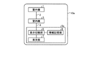
図3は、本実施の形態の空気調和機システムの構成例を示す図である。空気調和機システム10aは、室外機1と、通信線2と、室内機3と、通信線4と、リモコン5aと、から構成される。リモコン5aは、表示切換部6と、表示部7と、情報記憶部8と、を備える。
FIG. 3 is a diagram illustrating a configuration example of the air conditioner system according to the present embodiment. The air conditioner system 10a includes an outdoor unit 1, a
表示切換部6は、表示部7に表示する情報を切り替える制御を行う。表示切換部6は、リモコン5aが備える物理スイッチでもよいし、プログラムの設定で切り換える様に構成してもよい。
The display switching unit 6 performs control to switch information displayed on the display unit 7. The display switching unit 6 may be a physical switch provided in the
表示部7は、表示切換部6の切り換え制御によって、ユーザーに対して空気調和機システム10aにおける運転モードや異常猶予状態等の情報を表示する。 The display unit 7 displays information such as an operation mode and an abnormal postponement state in the air conditioner system 10 a to the user by switching control of the display switching unit 6.
情報記憶部8は、室外機1および室内機3から取得した情報(例えば、運転モード、異常猶予情報など)を記憶する。情報記憶部8は、不揮発メモリで構成することで、リモコン5aの電源がOFFになった場合でも情報を保持しておくことが可能となる。
The information storage unit 8 stores information acquired from the outdoor unit 1 and the indoor unit 3 (for example, operation mode, abnormal grace information, etc.). By configuring the information storage unit 8 with a non-volatile memory, it is possible to retain information even when the power source of the
つづいて、空気調和機システム10a内で、異常猶予を検出した場合のリモコン5aにおける動作について説明する。なお、リモコン5aが室外機1および室内機3から異常猶予状態等の情報を取得する方法は、実施の形態1と同様である。
Subsequently, the operation of the
リモコン5aでは、表示切換部6を、例えば、「通常表示」、「異常猶予表示」といった2つの切換機能で構成する。表示切換部6は、設定が「通常表示」の場合、運転モード・設定温度といった情報を表示部7に表示し、設定が「異常猶予表示」の場合、室外機1および室内機3から受信した異常猶予情報の情報を表示部7に表示する。
In the
また、情報記憶部8を活用した表示切換部6の動作例として、「通常表示」、「異常猶予表示」、「過去履歴」といった3つの機能を表示切換部6に設けることで、「通常表示」、「異常猶予表示」の他、情報記憶部8に記憶している情報を表示部7に表示する「過去履歴」機能をリモコン5aに付加することが可能となる。リモコン5aにおいて「過去履歴」を表示するため、表示切換部6または室内機3との通信を行う図示しない通信部が、情報記憶部8に記録する情報にタイムスタンプ(年/月/日)を付加する。これにより、表示切換部6では、過去履歴を表示する際に時系列順に取得した情報を表示することができる。
Further, as an example of the operation of the display switching unit 6 utilizing the information storage unit 8, by providing the display switching unit 6 with three functions such as “normal display”, “abnormal grace display”, and “past history”, “normal display” In addition to “Abnormal Grace Display”, a “past history” function for displaying information stored in the information storage unit 8 on the display unit 7 can be added to the
以上説明したように、本実施の形態によれば、リモコン5aは、表示する内容を切り換え可能な表示切換部6と、運転モードや異常猶予状態等を表示する表示部7と、室外機1・室内機3から受信する異常猶予状態等の情報を記憶する情報記憶部8と、を備える構成とした。これにより、市場での定期メンテナンス時にリモコン5aの表示を切り換えることで、室外機1および室内機3が正常に動作しているのか(異常または異常猶予となっていないか)を判断することができる。
As described above, according to the present embodiment, the
また、市場にて空気調和機システム10aに発生した異常調査の際、従来では異常が発生して初めてシステムの確認・調査が可能であったが、異常発生前の状態(異常猶予状態)から確認することが可能となる。そのため、異常猶予状態を経た異常発生までの全ての流れを追うことが可能であり、異常要因解析の精度を向上させることができる。 In addition, when investigating an abnormality that occurred in the air conditioner system 10a in the market, it was previously possible to check and investigate the system for the first time after the occurrence of the abnormality. It becomes possible to do. Therefore, it is possible to follow the entire flow from the occurrence of an abnormal postponement until the occurrence of an abnormality, and the accuracy of the abnormality factor analysis can be improved.
また、リモコン5aに記憶する情報にタイムスタンプを付加した場合、時系列を追うことができるため、慢性的に異常猶予状態を検出しているため定期的に異常となっているのか、突発的な要因のため異常猶予となり異常検出しているか、など異常解析を行う際の判断基準を追加することが可能となる。
In addition, when a time stamp is added to the information stored in the
実施の形態3.
本実施の形態では、リモコンが記憶する情報を切換可能とする。実施の形態2と異なる部分について説明する。
In the present embodiment, information stored in the remote controller can be switched. A different part from
図4は、本実施の形態の空気調和機システムの構成例を示す図である。空気調和機システム10bは、室外機1と、通信線2と、室内機3と、通信線4と、リモコン5bと、から構成される。リモコン5bは、表示切換部6と、表示部7と、情報記憶部8と、情報設定部9と、を備える。情報設定部9は、表示切換部6および情報記憶部8が対象とする情報の切り換え制御を行う。
FIG. 4 is a diagram illustrating a configuration example of the air conditioner system according to the present embodiment. The
情報設定部9の機能の一例として、「全データ記憶」「データ個別」と機能を選択できる構成とする。この機能の選択は、ユーザーが任意に行ってもよく、デフォルトとしてプログラムで決定させる方式としてもよい。情報設定部9では、この機能設定により、表示切換部6および情報記憶部8について以下の制御を行う。ここでは、制御の一例として、室内機3から取得する情報が「運転モード」「設定温度」「異常猶予」「異常有無」であり、情報設定部9が「全データ記憶」「データ個別」の2つの切り換え機能を有する場合を想定して説明する。
As an example of the function of the information setting unit 9, “all data storage” and “data individual” can be selected. The selection of this function may be arbitrarily performed by the user, or may be determined by a program as a default. The information setting unit 9 performs the following control for the display switching unit 6 and the information storage unit 8 by this function setting. Here, as an example of control, the information acquired from the
情報設定部9の設定が「全データ記憶」の場合、表示切換部6は、室外機1・室内機3から取得する情報の全データについて表示切り換えを行うことができる。例えば、室内機3から取得する情報の「運転モード」「設定温度」「異常猶予」「異常有無」全てを表示部7に表示にすることができる。また、情報記憶部8では、室外機1・室内機3から取得する全情報を記憶することができる。
When the setting of the information setting unit 9 is “all data storage”, the display switching unit 6 can perform display switching for all data of information acquired from the outdoor unit 1 and the
つぎに、情報設定部9の設定が「データ個別」の場合、表示切換部6は、室外機1・室内機3から取得する情報を個別に表示切り換えを行うことができる。例えば、「データ個別」の内容を「運転モード」「異常猶予」に設定した場合、表示部7には「運転モード」「異常猶予」情報だけ表示することができる。また、情報記憶部8では、室外機1・室内機3から取得する情報のうち「運転モード」「異常猶予」の情報のみ記憶することができる。
Next, when the setting of the information setting unit 9 is “individual data”, the display switching unit 6 can individually switch the information acquired from the outdoor unit 1 and the
なお、上記で説明した情報設定部9の設定および動作は一例であり、上記以外にもより詳細な設定として、データを記憶しない設定を行うことも可能である。また、設定する機能の内容によって、表示部7に表示する情報と情報記憶部8に記憶する情報を区別することも可能である。 It should be noted that the setting and operation of the information setting unit 9 described above are merely examples, and settings other than those described above can be performed without storing data. Further, the information displayed on the display unit 7 and the information stored in the information storage unit 8 can be distinguished depending on the content of the function to be set.
以上説明したように、本実施の形態によれば、リモコン5bでは、情報設定部9において、表示部7に表示する情報の内容、および情報記憶部8に記憶する情報の内容を切り換え可能とする。情報記憶部8は不揮発メモリで構成されている場合、記憶可能なデータ量は記憶容量に依存することになり、無限のデータを記憶することは不可能である。そのため、情報設定部9によって、記憶するデータを選択して記憶することが可能となり、不要なデータを記憶しないことで従来よりも有益な情報を多く記憶することが可能となる。これにより、市場で発生した異常解析などで使用することができる有益なデータを多く記憶することができ、異常要因解析の精度を向上させることができる。 As described above, according to the present embodiment, in the remote controller 5b, the information setting unit 9 can switch the content of information displayed on the display unit 7 and the content of information stored in the information storage unit 8. . When the information storage unit 8 is composed of a non-volatile memory, the amount of data that can be stored depends on the storage capacity, and infinite data cannot be stored. Therefore, it is possible to select and store data to be stored by the information setting unit 9, and it is possible to store more useful information than before by not storing unnecessary data. This makes it possible to store a lot of useful data that can be used in anomaly analysis that has occurred in the market, and improve the accuracy of the anomaly factor analysis.
また、情報設定部9において記憶する情報を設定できるため、ユーザーのニーズにあった設定を行うことが可能であり、サービス性を向上させることが可能となる。 In addition, since information stored in the information setting unit 9 can be set, it is possible to make settings that meet the needs of the user, and to improve serviceability.
以上のように、本発明にかかる空気調和機システムは、室内の空気調和制御に有用であり、特に、リモコンを備えたシステムに適している。 As described above, the air conditioner system according to the present invention is useful for indoor air conditioning control, and is particularly suitable for a system including a remote controller.
1 室外機
2 通信線
3 室内機
4 通信線
5、5a、5b リモコン
6 表示切換部
7 表示部
8 情報記憶部
9 情報設定部
10、10a、10b 空気調和機システム
DESCRIPTION OF SYMBOLS 1
Claims (8)
前記室外機は、正常な状態から異常が発生するまでの状態を示す異常猶予状態を検出した場合、異常猶予状態検出情報を前記室内機経由で前記リモコンへ伝達し、
前記室内機は、異常猶予状態を検出した場合、異常猶予状態検出情報を前記リモコンへ伝達し、
前記リモコンは、前記室外機および前記室内機から前記異常猶予状態検出情報を取得する、
ことを特徴とする空気調和機システム。 An air conditioner system that includes an outdoor unit, an indoor unit, and a remote controller, and that communicates operating information between the outdoor unit and the indoor unit and between the indoor unit and the remote controller,
When the outdoor unit detects an abnormal grace state indicating a state from a normal state until an abnormality occurs, the abnormal grace state detection information is transmitted to the remote controller via the indoor unit,
When the indoor unit detects an abnormal grace state, it transmits abnormal grace state detection information to the remote control,
The remote control acquires the abnormal postponement state detection information from the outdoor unit and the indoor unit;
An air conditioner system characterized by that.
前記運転情報および前記異常猶予状態情報を表示する表示手段と、
前記表示手段に表示する情報として、前記運転情報または前記異常猶予状態情報に切り換える制御を行う表示切換手段と、
を備えることを特徴とする請求項1に記載の空気調和機システム。 The remote control is
Display means for displaying the driving information and the abnormal postponement status information;
As information to be displayed on the display means, display switching means for performing control to switch to the operation information or the abnormal grace state information;
The air conditioner system according to claim 1, comprising:
前記室外機および前記室内機から取得した前記運転情報および前記異常猶予状態情報を記憶する情報記憶手段、
を備え、
前記表示切換手段は、前記表示手段に表示する情報として、前記情報記憶手段に記憶されている情報に切り換える制御を行う、
ことを特徴とする請求項2に記載の空気調和機システム。 The remote control is
Information storage means for storing the operation information acquired from the outdoor unit and the indoor unit and the abnormal postponement status information;
With
The display switching means performs control to switch to information stored in the information storage means as information to be displayed on the display means.
The air conditioner system according to claim 2.
前記表示切換手段および前記情報記憶手段が対象とする情報を設定する情報設定手段、
を備え、
前記表示切換手段は、前記情報設定手段により設定された情報について前記表示手段に表示する情報の切り替え制御を行い、
前記情報記憶手段は、前記情報設定手段により設定された情報を記憶する、
ことを特徴とする請求項3に記載の空気調和機システム。 The remote control is
Information setting means for setting information targeted by the display switching means and the information storage means;
With
The display switching means performs switching control of information displayed on the display means for information set by the information setting means,
The information storage means stores the information set by the information setting means;
The air conditioner system according to claim 3.
前記室外機が、正常な状態から異常が発生するまでの状態を示す異常猶予状態を検出した場合、異常猶予状態検出情報を前記室内機経由で前記リモコンへ伝達し、前記室内機が、異常猶予状態を検出した場合、異常猶予状態検出情報を前記リモコンへ伝達する場合、
前記室外機および前記室内機から前記異常猶予状態検出情報を取得する、
ことを特徴とするリモコン。 It is composed of an outdoor unit, an indoor unit, and a remote control, and the remote control in the air conditioner system that communicates operation information between the outdoor unit and the indoor unit and between the indoor unit and the remote control,
When the outdoor unit detects an abnormal grace state indicating a state from a normal state until an abnormality occurs, the abnormal grace state detection information is transmitted to the remote controller via the indoor unit, and the indoor unit When detecting the status, when transmitting abnormal postponement status detection information to the remote control,
Obtaining the abnormal postponement state detection information from the outdoor unit and the indoor unit,
A remote control characterized by that.
前記表示手段に表示する情報として、前記運転情報または前記異常猶予状態情報に切り換える制御を行う表示切換手段と、
を備えることを特徴とする請求項5に記載のリモコン。 Display means for displaying the driving information and the abnormal postponement status information;
As information to be displayed on the display means, display switching means for performing control to switch to the operation information or the abnormal grace state information;
The remote control according to claim 5, further comprising:
を備え、
前記表示切換手段は、前記表示手段に表示する情報として、前記情報記憶手段に記憶されている情報に切り換える制御を行う、
ことを特徴とする請求項6に記載のリモコン。 Information storage means for storing the operation information acquired from the outdoor unit and the indoor unit and the abnormal postponement status information;
With
The display switching means performs control to switch to information stored in the information storage means as information to be displayed on the display means.
The remote control according to claim 6.
を備え、
前記表示切換手段は、前記情報設定手段により設定された情報について前記表示手段に表示する情報の切り替え制御を行い、
前記情報記憶手段は、前記情報設定手段により設定された情報を記憶する、
ことを特徴とする請求項7に記載のリモコン。 Information setting means for setting information targeted by the display switching means and the information storage means;
With
The display switching means performs switching control of information displayed on the display means for information set by the information setting means,
The information storage means stores the information set by the information setting means;
The remote control according to claim 7.
Priority Applications (1)
| Application Number | Priority Date | Filing Date | Title |
|---|---|---|---|
| JP2012038854A JP2013174385A (en) | 2012-02-24 | 2012-02-24 | Air conditioner system, and remote controller |
Applications Claiming Priority (1)
| Application Number | Priority Date | Filing Date | Title |
|---|---|---|---|
| JP2012038854A JP2013174385A (en) | 2012-02-24 | 2012-02-24 | Air conditioner system, and remote controller |
Publications (2)
| Publication Number | Publication Date |
|---|---|
| JP2013174385A true JP2013174385A (en) | 2013-09-05 |
| JP2013174385A5 JP2013174385A5 (en) | 2014-08-07 |
Family
ID=49267436
Family Applications (1)
| Application Number | Title | Priority Date | Filing Date |
|---|---|---|---|
| JP2012038854A Pending JP2013174385A (en) | 2012-02-24 | 2012-02-24 | Air conditioner system, and remote controller |
Country Status (1)
| Country | Link |
|---|---|
| JP (1) | JP2013174385A (en) |
Cited By (3)
| Publication number | Priority date | Publication date | Assignee | Title |
|---|---|---|---|---|
| WO2016189665A1 (en) * | 2015-05-26 | 2016-12-01 | 三菱電機株式会社 | Remote controller for air conditioning system |
| WO2019116885A1 (en) | 2017-12-13 | 2019-06-20 | ダイキン工業株式会社 | Air-conditioning system, remote control device, and method for saving operation data history of air conditioner |
| WO2019224890A1 (en) * | 2018-05-21 | 2019-11-28 | 三菱電機株式会社 | Air-conditioning system remote controller and air-conditioning system |
Citations (4)
| Publication number | Priority date | Publication date | Assignee | Title |
|---|---|---|---|---|
| JPH09243149A (en) * | 1996-03-12 | 1997-09-16 | Matsushita Refrig Co Ltd | Controller for air conditioner |
| JP2004205194A (en) * | 2002-10-30 | 2004-07-22 | Hitachi Ltd | Refrigeration and air conditioning systems |
| JP2009229009A (en) * | 2008-03-24 | 2009-10-08 | Mitsubishi Electric Corp | Remote control device |
| JP2010210121A (en) * | 2009-03-09 | 2010-09-24 | Mitsubishi Electric Corp | Air conditioner |
-
2012
- 2012-02-24 JP JP2012038854A patent/JP2013174385A/en active Pending
Patent Citations (4)
| Publication number | Priority date | Publication date | Assignee | Title |
|---|---|---|---|---|
| JPH09243149A (en) * | 1996-03-12 | 1997-09-16 | Matsushita Refrig Co Ltd | Controller for air conditioner |
| JP2004205194A (en) * | 2002-10-30 | 2004-07-22 | Hitachi Ltd | Refrigeration and air conditioning systems |
| JP2009229009A (en) * | 2008-03-24 | 2009-10-08 | Mitsubishi Electric Corp | Remote control device |
| JP2010210121A (en) * | 2009-03-09 | 2010-09-24 | Mitsubishi Electric Corp | Air conditioner |
Cited By (6)
| Publication number | Priority date | Publication date | Assignee | Title |
|---|---|---|---|---|
| WO2016189665A1 (en) * | 2015-05-26 | 2016-12-01 | 三菱電機株式会社 | Remote controller for air conditioning system |
| JPWO2016189665A1 (en) * | 2015-05-26 | 2017-08-10 | 三菱電機株式会社 | Remote controller for air conditioning system |
| US10365002B2 (en) | 2015-05-26 | 2019-07-30 | Mitsubishi Electric Corporation | Remote controller of air-conditioning system |
| WO2019116885A1 (en) | 2017-12-13 | 2019-06-20 | ダイキン工業株式会社 | Air-conditioning system, remote control device, and method for saving operation data history of air conditioner |
| US11649979B2 (en) | 2017-12-13 | 2023-05-16 | Daikin Industries, Ltd. | Air conditioning system, remote controller, and method for saving history of operation data on air conditioner |
| WO2019224890A1 (en) * | 2018-05-21 | 2019-11-28 | 三菱電機株式会社 | Air-conditioning system remote controller and air-conditioning system |
Similar Documents
| Publication | Publication Date | Title |
|---|---|---|
| US20160217674A1 (en) | Remote monitoring of an hvac system for fault detection and diagnostics | |
| EP2954273B1 (en) | Controlling a refrigeration appliance with a portable electronic device | |
| JP6625239B2 (en) | Air conditioner and air conditioning system | |
| JPWO2015111203A1 (en) | Air conditioner trial run application and air conditioner trial run system | |
| US20130197698A1 (en) | HVAC System Fault Root Cause Self-Determination | |
| US20160313750A1 (en) | Geo-fencing with diagnostic feature | |
| JP5606334B2 (en) | Air conditioning management device, air conditioning management method, and program | |
| US8971252B2 (en) | Wireless gateway apparatus, communication system, and wireless communication method | |
| EP2950010B1 (en) | Air conditioner | |
| JP2017053571A (en) | Inspection system of refrigerant leakage detector, and air conditioning system | |
| US20160330623A1 (en) | Communication system, beacon device, communication method, and electronic appliance | |
| JP6345240B2 (en) | Display device, method and program | |
| JP2016095683A (en) | Measuring apparatus and control method thereof, management unit and control method thereof and measurement system | |
| WO2015031500A4 (en) | Food management system | |
| JP2013174385A (en) | Air conditioner system, and remote controller | |
| JP4765798B2 (en) | Diagnostic device and air conditioning management device | |
| KR100876223B1 (en) | Temperature sensing and control system | |
| JP6639952B2 (en) | Inspection system for alarm using mobile terminal and inspection method using the same | |
| JP2011242085A (en) | Air conditioner | |
| JP2005016871A (en) | Control device for household electric appliance and control device for refrigerator | |
| KR101852633B1 (en) | A network system and a control method the same | |
| JP2017098834A (en) | Centralized management system and communication failure factor analysis method | |
| JP7431535B2 (en) | Server and control system and control program | |
| JP2007192492A (en) | Self-diagnosis display device for air-conditioner | |
| JP2009193317A (en) | Electronic device |
Legal Events
| Date | Code | Title | Description |
|---|---|---|---|
| A521 | Written amendment |
Free format text: JAPANESE INTERMEDIATE CODE: A523 Effective date: 20140625 |
|
| A621 | Written request for application examination |
Free format text: JAPANESE INTERMEDIATE CODE: A621 Effective date: 20140625 |
|
| A977 | Report on retrieval |
Free format text: JAPANESE INTERMEDIATE CODE: A971007 Effective date: 20150225 |
|
| A131 | Notification of reasons for refusal |
Free format text: JAPANESE INTERMEDIATE CODE: A131 Effective date: 20150303 |
|
| A521 | Written amendment |
Free format text: JAPANESE INTERMEDIATE CODE: A523 Effective date: 20150416 |
|
| A02 | Decision of refusal |
Free format text: JAPANESE INTERMEDIATE CODE: A02 Effective date: 20150929 |