JP2013166324A - Droplet ejection device - Google Patents
Droplet ejection device Download PDFInfo
- Publication number
- JP2013166324A JP2013166324A JP2012031444A JP2012031444A JP2013166324A JP 2013166324 A JP2013166324 A JP 2013166324A JP 2012031444 A JP2012031444 A JP 2012031444A JP 2012031444 A JP2012031444 A JP 2012031444A JP 2013166324 A JP2013166324 A JP 2013166324A
- Authority
- JP
- Japan
- Prior art keywords
- ultraviolet
- irradiation unit
- ultraviolet irradiation
- droplet
- region
- Prior art date
- Legal status (The legal status is an assumption and is not a legal conclusion. Google has not performed a legal analysis and makes no representation as to the accuracy of the status listed.)
- Withdrawn
Links
- 230000001678 irradiating effect Effects 0.000 claims abstract description 11
- 230000031700 light absorption Effects 0.000 claims description 38
- 239000007788 liquid Substances 0.000 claims description 13
- 230000015572 biosynthetic process Effects 0.000 claims description 10
- 230000000740 bleeding effect Effects 0.000 abstract description 5
- 239000000976 ink Substances 0.000 description 74
- 238000010586 diagram Methods 0.000 description 12
- 239000000203 mixture Substances 0.000 description 12
- 230000000694 effects Effects 0.000 description 4
- 230000004048 modification Effects 0.000 description 4
- 238000012986 modification Methods 0.000 description 4
- 239000004744 fabric Substances 0.000 description 3
- 238000009281 ultraviolet germicidal irradiation Methods 0.000 description 3
- 238000000034 method Methods 0.000 description 2
- 229920000742 Cotton Polymers 0.000 description 1
- 238000010521 absorption reaction Methods 0.000 description 1
- 239000002985 plastic film Substances 0.000 description 1
- 229920006255 plastic film Polymers 0.000 description 1
- 239000002759 woven fabric Substances 0.000 description 1
Images
Landscapes
- Ink Jet (AREA)
Abstract
【課題】インクのにじみ等の発生を防止する。
【解決手段】ヘッドユニットと、紫外線照射ユニットと、を備え、ヘッドユニットでは、ヘッドユニットを走査方向から透視した場合に、第1吐出ヘッドに設けられた複数のノズルの一部と第2吐出ヘッドに設けられた複数のノズルの一部とが重複するように、第1吐出ヘッドと第2吐出ヘッドとが配置され、紫外線照射ユニットでは、第1吐出ヘッドから吐出された第1紫外線硬化型インクの第1液滴ドットが形成された第1領域に対して第1硬化要素を含む紫外線を照射する第1紫外線照射部と、第2吐出ヘッドから吐出された第2紫外線硬化型インクの第2液滴ドットが形成された第2領域に対して第2硬化要素を含む紫外線を照射する第2紫外線照射部と、第1液滴ドットと第2液滴ドットとが混在可能なドット混在可能領域に対して第1硬化要素と第2硬化要素とを含む紫外線を照射する第3紫外線照射部と、が配置された。
【選択図】図2Generation of ink bleeding and the like is prevented.
A head unit and an ultraviolet irradiation unit are provided. In the head unit, when the head unit is seen through from the scanning direction, a part of a plurality of nozzles provided in the first discharge head and the second discharge head The first discharge head and the second discharge head are arranged so that some of the plurality of nozzles provided in the first and second nozzles overlap each other, and in the ultraviolet irradiation unit, the first ultraviolet curable ink discharged from the first discharge head A first ultraviolet irradiation unit that irradiates the first region in which the first droplet dots are formed with ultraviolet rays including a first curing element, and a second ultraviolet curable ink ejected from the second ejection head. A second ultraviolet irradiation unit that irradiates the second region in which the droplet dots are formed with ultraviolet rays including the second curing element, and a dot-mixable region in which the first droplet dots and the second droplet dots can be mixed Against A third ultraviolet irradiation unit for irradiating ultraviolet rays including a first curable component and a second curing component, are arranged.
[Selection] Figure 2
Description
本発明は、液滴吐出装置に関する。 The present invention relates to a droplet discharge device.
配列された複数の記録ヘッドと、各記録ヘッドに対応して配置された複数の紫外線照射部等を備え、各記録ヘッドから吐出されるインクの特性に合わせて、紫外線の強度、波長及び照射時間のいずれか異なる照射条件で紫外線を照射する記録装置の構成が知られている(例えば、特許文献1参照)。 A plurality of arranged recording heads and a plurality of ultraviolet irradiation units arranged corresponding to the respective recording heads are provided, and the intensity, wavelength and irradiation time of ultraviolet rays are adjusted according to the characteristics of the ink ejected from each recording head. A configuration of a recording apparatus that irradiates ultraviolet rays under any of these irradiation conditions is known (see, for example, Patent Document 1).
しかしながら、上記の記録装置では、例えば、吐出ヘッドの吐出走査において、隣接する各ヘッドから吐出された異なるインクドットが混在する場合には、混在する領域に塗布された各インクドットに対して適切条件で紫外線を照射することができず、一部インクが硬化せずにじみ等の発生により画像品質を低下させてしまう、という課題があった。 However, in the above-described recording apparatus, for example, when different ink dots ejected from adjacent heads coexist in the ejection scan of the ejection head, an appropriate condition is set for each ink dot applied to the mixed area. In other words, the ink cannot be irradiated with ultraviolet rays, and some of the ink is not cured, and the image quality is deteriorated due to bleeding or the like.
本発明は、上述の課題の少なくとも一部を解決するためになされたものであり、以下の形態または適用例として実現することが可能である。 SUMMARY An advantage of some aspects of the invention is to solve at least a part of the problems described above, and the invention can be implemented as the following forms or application examples.
[適用例1]本適用例にかかる液滴吐出装置は、第1紫外線硬化型インクを吐出する第1吐出ヘッドと、第2紫外線硬化型インクを吐出する第2吐出ヘッドと、を有するヘッドユニットと、前記第1吐出ヘッド及び前記第2吐出ヘッドから吐出された前記第1紫外線硬化型インク及び前記第2紫外線硬化型インクに対して紫外線を照射する紫外線照射ユニットと、を備え、前記ヘッドユニットでは、前記ヘッドユニットを走査方向から透視した場合に、前記第1吐出ヘッドに設けられた複数のノズルの一部と前記第2吐出ヘッドに設けられた複数のノズルの一部とが重複するように、前記第1吐出ヘッドと前記第2吐出ヘッドとが配置され、前記紫外線照射ユニットでは、前記第1吐出ヘッドから吐出された前記第1紫外線硬化型インクの第1液滴ドットが形成された第1領域に対して第1硬化要素を含む紫外線を照射する第1紫外線照射部と、前記第2吐出ヘッドから吐出された前記第2紫外線硬化型インクの第2液滴ドットが形成された第2領域に対して第2硬化要素を含む紫外線を照射する第2紫外線照射部と、前記第1液滴ドットと前記第2液滴ドットとが混在可能なドット混在可能領域に対して前記第1硬化要素と前記第2硬化要素とを含む紫外線を照射する第3紫外線照射部と、が配置されたことを特徴とする。 Application Example 1 A droplet discharge device according to this application example includes a first discharge head that discharges a first ultraviolet curable ink and a second discharge head that discharges a second ultraviolet curable ink. And an ultraviolet irradiation unit that irradiates ultraviolet rays to the first ultraviolet curable ink and the second ultraviolet curable ink discharged from the first discharge head and the second discharge head, and the head unit. Then, when the head unit is seen through from the scanning direction, a part of the plurality of nozzles provided in the first ejection head and a part of the plurality of nozzles provided in the second ejection head overlap. In addition, the first ejection head and the second ejection head are arranged, and the ultraviolet irradiation unit includes a first ejection of the first ultraviolet curable ink ejected from the first ejection head. A first ultraviolet irradiation unit that irradiates ultraviolet rays including a first curing element to the first region in which droplet dots are formed; and a second liquid of the second ultraviolet curable ink ejected from the second ejection head. The second ultraviolet irradiation unit that irradiates the second region in which the droplet dots are formed with the ultraviolet rays including the second curing element, and the dot mixture that can mix the first droplet dots and the second droplet dots is possible A third ultraviolet irradiation unit that irradiates the region with ultraviolet rays including the first curing element and the second curing element is arranged.
この構成によれば、第1領域における第1紫外線硬化型インクの第1液滴ドットは第1紫外線照射部から照射された紫外線によって硬化される。また、第2領域における第2紫外線硬化型インクの第2液滴ドットは第2紫外線照射部から照射された紫外線によって硬化される。ここで、第1紫外線照射部は、第1紫外線硬化型インクを硬化させる第1硬化要素を有している。第1硬化要素としては、例えば、第1紫外線硬化型インクに対応する紫外線の強度や紫外線の波長帯域等である。すなわち、第1硬化要素は、第1紫外線硬化型インクを効率的に硬化させるための要素である。同様にして、第2紫外線照射部は、第2紫外線硬化型インクを効率的に硬化させるための第2硬化要素を有している。さらに、ドット混在領域における第1液滴ドットと第2液滴ドットは第3紫外線照射部から照射された紫外線によって硬化される。第3紫外線照射部は、第1紫外線硬化型インクを硬化させる第1要素と第2紫外線硬化型インクを硬化させる第2要素を有しているため、第1液滴ドットに対して第1要素が有効にはたらき、第2液滴ドットに対して第2要素が有効にはたらいて各液滴ドットが硬化される。従って、第1領域、第2領域及びドット混在領域において各液滴ドットが確実に硬化されるため、にじみ等の発生が抑制され、画像品質を向上させることができる。 According to this configuration, the first droplet dots of the first ultraviolet curable ink in the first region are cured by the ultraviolet rays irradiated from the first ultraviolet irradiation unit. Further, the second droplet dots of the second ultraviolet curable ink in the second region are cured by the ultraviolet rays irradiated from the second ultraviolet irradiation unit. Here, the first ultraviolet irradiation unit has a first curing element that cures the first ultraviolet curable ink. Examples of the first curing element include the intensity of ultraviolet rays corresponding to the first ultraviolet curable ink and the wavelength band of ultraviolet rays. That is, the first curing element is an element for efficiently curing the first ultraviolet curable ink. Similarly, the 2nd ultraviolet irradiation part has the 2nd hardening element for hardening the 2nd ultraviolet curable ink efficiently. Further, the first droplet dots and the second droplet dots in the dot mixed region are cured by the ultraviolet rays irradiated from the third ultraviolet irradiation unit. The third ultraviolet irradiation unit has a first element that cures the first ultraviolet curable ink and a second element that cures the second ultraviolet curable ink, and therefore the first element with respect to the first droplet dot. Works effectively, and the second element works effectively with respect to the second droplet dots to cure each droplet dot. Accordingly, since each droplet dot is reliably cured in the first region, the second region, and the dot mixed region, the occurrence of bleeding and the like is suppressed, and the image quality can be improved.
[適用例2]上記適用例にかかる液滴吐出装置の前記第3紫外線照射部では、前記ドット混在可能領域における前記第1液滴ドットと前記第2液滴ドットの形成状態に応じて、前記第1硬化要素を含む紫外線と前記第2硬化要素を含む紫外線の双方、または、一方を照射することを特徴とする。 Application Example 2 In the third ultraviolet irradiation unit of the droplet discharge device according to the application example, the first droplet dots and the second droplet dots in the dot-mixable region, It is characterized by irradiating both or one of the ultraviolet ray including the first curing element and the ultraviolet ray including the second curing element.
この構成によれば、ドット混在領域における第1液滴ドットと第2液滴ドットの形成状態に応じて第3紫外線照射部から適正な紫外線が選択的に照射されるので、無駄な紫外線を照射することなく効率よく各インクを硬化させることができる。 According to this configuration, since appropriate ultraviolet rays are selectively emitted from the third ultraviolet ray irradiation unit according to the formation state of the first droplet dots and the second droplet dots in the dot mixed region, unnecessary ultraviolet rays are emitted. Each ink can be cured efficiently without the need to do so.
[適用例3]上記適用例にかかる液滴吐出装置の前記第1紫外線照射部では、前記第1紫外線硬化型インクの第1光吸収波長を含み、前記第2紫外線照射部では、前記第2紫外線硬化型インクの第2光吸収波長を含み、前記第3紫外線照射部では、前記第1光吸収波長と前記第2光吸収波長とを含むことを特徴とする。 Application Example 3 The first ultraviolet irradiation unit of the droplet discharge device according to the application example includes a first light absorption wavelength of the first ultraviolet curable ink, and the second ultraviolet irradiation unit includes the second ultraviolet irradiation unit. A second light absorption wavelength of the ultraviolet curable ink is included, and the third ultraviolet irradiation unit includes the first light absorption wavelength and the second light absorption wavelength.
この構成によれば、第1紫外線照射部は第1光吸収波長を含む紫外線を照射することが可能であり、第1領域における第1液滴ドットは、当該第1光吸収波長を含む紫外線が照射させることにより硬化される。また、第2紫外線照射部は第2光吸収波長を含む紫外線を照射することが可能であり、第2領域における第2液滴ドットは、第2光吸収波長を含む紫外線が照射させることにより硬化される。さらに、第3紫外線照射部は第1光吸収波長と第2光吸収波長を含む紫外線を照射することが可能であり、ドット混在領域における第1液滴ドット及び第2液滴ドットは、第1光吸収波長および第2光吸収波長を含む紫外線が照射させることにより硬化される。これにより、光が吸収される波長が異なるインクが塗布された場合であっても、各インクに対応した波長を含む紫外線が照射されるので、効率的にインクを硬化することができる。 According to this configuration, the first ultraviolet irradiation unit can irradiate ultraviolet rays including the first light absorption wavelength, and the first droplet dots in the first region are irradiated with ultraviolet rays including the first light absorption wavelength. It is cured by irradiation. Further, the second ultraviolet ray irradiation unit can irradiate ultraviolet rays including the second light absorption wavelength, and the second droplet dots in the second region are cured by being irradiated with ultraviolet rays including the second light absorption wavelength. Is done. Further, the third ultraviolet irradiation unit can irradiate ultraviolet rays including the first light absorption wavelength and the second light absorption wavelength, and the first droplet dots and the second droplet dots in the dot mixture region are the first It is hardened by irradiating with ultraviolet rays including the light absorption wavelength and the second light absorption wavelength. Thereby, even when inks having different wavelengths for absorbing light are applied, ultraviolet rays including wavelengths corresponding to the respective inks are irradiated, so that the inks can be cured efficiently.
[適用例4]上記適用例にかかる液滴吐出装置は、前記第1紫外線照射部では、前記第1紫外線硬化型インクに対応する第1照射強度を含み、前記第2紫外線照射部では、前記第2紫外線硬化型インクに対応する第2照射強度を含み、前記第3紫外線照射部では、前記第1照射強度と前記第2照射強度を含むことを特徴とする。 Application Example 4 In the liquid droplet ejection device according to the application example, the first ultraviolet irradiation unit includes a first irradiation intensity corresponding to the first ultraviolet curable ink, and the second ultraviolet irradiation unit includes the first irradiation intensity. A second irradiation intensity corresponding to the second ultraviolet curable ink is included, and the third ultraviolet irradiation unit includes the first irradiation intensity and the second irradiation intensity.
この構成によれば、第1紫外線照射部は第1照射強度を含む紫外線を照射することが可能であり、第1領域における第1液滴ドットは、当該第1照射強度を含む紫外線が照射させることにより硬化される。また、第2紫外線照射部は第2照射強度を含む紫外線を照射することが可能であり、第2領域における第2液滴ドットは、第2照射強度を含む紫外線が照射させることにより硬化される。さらに、第3紫外線照射部は第1照射強度と第2照射強度を含む紫外線を照射することが可能であり、ドット混在領域における第1液滴ドット及び第2液滴ドットは、第1照射強度または第2照射強度を含む紫外線が照射させることにより硬化される。これにより、紫外線の照射強度により硬化特性が異なるインクが塗布された場合であっても、各インクに対応した紫外線照射強度を含む紫外線が照射されるので、効率的にインクを硬化することができる。 According to this configuration, the first ultraviolet irradiation unit can irradiate ultraviolet rays including the first irradiation intensity, and the first droplet dots in the first region are irradiated with the ultraviolet rays including the first irradiation intensity. Can be cured. Further, the second ultraviolet irradiation unit can irradiate ultraviolet rays including the second irradiation intensity, and the second droplet dots in the second region are cured by being irradiated with the ultraviolet rays including the second irradiation intensity. . Further, the third ultraviolet irradiation unit can irradiate ultraviolet rays including the first irradiation intensity and the second irradiation intensity, and the first droplet dot and the second droplet dot in the dot mixed region have the first irradiation intensity. Or it hardens | cures by irradiating the ultraviolet-ray containing 2nd irradiation intensity | strength. As a result, even when ink having different curing characteristics depending on the irradiation intensity of ultraviolet rays is applied, ultraviolet rays including the ultraviolet irradiation intensity corresponding to each ink are irradiated, so that the ink can be cured efficiently. .
以下、本発明の第1及び第2実施形態について、図面を参照して説明する。なお、以下の各図においては、各層や各部材を認識可能な程度の大きさにするため、各層や各部材の尺度を実際とは異ならせて示している。 Hereinafter, first and second embodiments of the present invention will be described with reference to the drawings. In the following drawings, the scale of each layer and each member is shown different from the actual scale so that each layer and each member can be recognized.
[第1実施形態]
まず、液滴吐出装置の構成について説明する。液滴吐出装置は、第1紫外線硬化型インクを吐出する第1吐出ヘッドと、第2紫外線硬化型インクを吐出する第2吐出ヘッドと、を有するヘッドユニットと、第1吐出ヘッド及び第2吐出ヘッドから吐出された第1紫外線硬化型インク及び第2紫外線硬化型インクに対して紫外線を照射する紫外線照射ユニットと、を備え、ヘッドユニットでは、ヘッドユニットを走査方向から透視した場合に、第1吐出ヘッドに設けられた複数のノズルの一部と第2吐出ヘッドに設けられた複数のノズルの一部とが重複するように、第1吐出ヘッドと第2吐出ヘッドとが配置され、紫外線照射ユニットでは、第1吐出ヘッドから吐出された第1紫外線硬化型インクの第1液滴ドットが形成された第1領域に対して第1硬化要素を含む紫外線を照射する第1紫外線照射部と、第2吐出ヘッドから吐出された第2紫外線硬化型インクの第2液滴ドットが形成された第2領域に対して第2硬化要素を含む紫外線を照射する第2紫外線照射部と、第1液滴ドットと第2液滴ドットとが混在可能なドット混在可能領域に対して第1硬化要素と第2硬化要素とを含む紫外線を照射する第3紫外線照射部と、が配置されたものである。以下、具体的に説明する。
[First Embodiment]
First, the configuration of the droplet discharge device will be described. The droplet discharge device includes a head unit having a first discharge head that discharges a first ultraviolet curable ink and a second discharge head that discharges a second ultraviolet curable ink, a first discharge head, and a second discharge head. An ultraviolet irradiation unit that irradiates the first ultraviolet curable ink and the second ultraviolet curable ink discharged from the head with ultraviolet rays, and the head unit has a first configuration when the head unit is seen through from the scanning direction. The first discharge head and the second discharge head are arranged so that a part of the plurality of nozzles provided in the discharge head and a part of the plurality of nozzles provided in the second discharge head overlap, and ultraviolet irradiation is performed. In the unit, the first purple that irradiates the first region where the first droplet dots of the first ultraviolet curable ink ejected from the first ejection head are formed with ultraviolet rays including the first curing element. And a second ultraviolet irradiation unit that irradiates the second region where the second droplet dots of the second ultraviolet curable ink ejected from the second ejection head are formed with ultraviolet rays including the second curing element. And a third ultraviolet irradiation unit that irradiates ultraviolet rays including the first curing element and the second curing element to the dot-mixable region where the first droplet dots and the second droplet dots can be mixed. It has been done. This will be specifically described below.
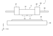
図1は、液滴吐出装置の構成を示す模式図である。図1に示すように、液滴吐出装置1は、ヘッドユニット2と、紫外線照射ユニット20と、ヘッドユニット2及び紫外線照射ユニット20をX軸方向に走査させる案内軸となるX走査軸30と、ワークWを載置するステージ40と、ステージ40をY軸方向に走査させる案内軸となるY走査軸(図示せず)等を備えている。そして、上記部材等を制御する制御部(図示せず)を備えている。また、本実施形態のワークWは、特に限定されず、例えば、プラスチックフィルムの他、綿布、麻布、絹布等の織布(布帛)や紙等を適用することができる。
FIG. 1 is a schematic diagram illustrating a configuration of a droplet discharge device. As shown in FIG. 1, the
ヘッドユニット2は、X走査軸30上を移動する移動手段を備え、ステージ40はY走査軸上を移動する移動手段を備えている。また、ヘッドユニット2は、X走査軸30に連結されたキャリッジ10と、キャリッジ10に搭載された第1及び第2吐出ヘッド11,12を備えている。第1及び第2吐出ヘッド11,12は、例えば、インクジェットヘッドである。
The
紫外線照射ユニット20は、第1紫外線照射ユニット21と第2紫外線照射ユニット22とを備えている。第1紫外線照射ユニット21と第2紫外線照射ユニット22は、ヘッドユニット2のX軸方向端部にそれぞれ配置されている。そして、本実施形態では、例えば、ヘッドユニット2をX軸方向(プラス方向)に移動させながら液滴を吐出する場合には、移動方向に対してヘッドユニット2の下流側となる第1紫外線照射ユニット21を駆動させ、ヘッドユニット2をX軸方向(マイナス方向)に移動させながら液滴を吐出する場合には、移動方向に対してヘッドユニット2の下流側となる第2紫外線照射ユニット22を駆動させる。
The
なお、本実施形態では、機能液としての紫外線硬化型インクを液滴として吐出する場合について説明する。また、第1吐出ヘッド11は第1紫外線硬化型インクを液滴として吐出し、第2吐出ヘッド12では第2紫外線硬化型インクを液滴として吐出する場合について説明する。本実施形態では、第1紫外線硬化型インクと第2紫外線硬化型インクでは光吸収波長領域が異なる場合における装置構成等について説明する。
In the present embodiment, a case where ultraviolet curable ink as a functional liquid is ejected as droplets will be described. Further, a case will be described in which the
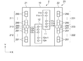
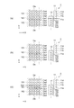
図2は、本実施形態にかかるヘッドユニット関連の構成を示す模式図であり、図3は、液滴吐出装置の動作を示す説明図である。具体的には、図2は、ヘッドユニット2における第1及び第2吐出ヘッド11,12の配列と、紫外線照射ユニット20における第1紫外線照射ユニット21と第2紫外線照射ユニット22の構成について示した模式図である。また、図3は、各液滴ドットが配置された領域に対する紫外線の照射方法を示す模式図である。
FIG. 2 is a schematic diagram illustrating a configuration related to the head unit according to the present embodiment, and FIG. 3 is an explanatory diagram illustrating an operation of the droplet discharge device. Specifically, FIG. 2 shows the arrangement of the first and second ejection heads 11 and 12 in the
図2に示すように、第1吐出ヘッド11は、複数のノズル11a〜11nを備えている。これら複数のノズル11a〜11nは、Y軸方向に列を成している。第2吐出ヘッド12は、複数のノズル12a〜12nを備えている。これら複数のノズル12a〜12nは、Y軸方向に列を成している。そして、ヘッドユニット2を走査方向(X軸方向)から透視した場合に、第1吐出ヘッド11に設けられた複数のノズル11a〜11nの一部と第2吐出ヘッド12に設けられた複数のノズル12a〜12nの一部とが重複するように、第1吐出ヘッド11と第2吐出ヘッド12とが配置されている。なお、本実施形態では、ヘッドユニット2の走査方向(X軸方向)に対して、第1吐出ヘッド11のノズル11aと第2吐出ヘッド12のノズル12aとが重複するように第1吐出ヘッド11と第2吐出ヘッド12とが配置されている。
As shown in FIG. 2, the
紫外線照射ユニット20は、第1紫外線照射ユニット21と第2紫外線照射ユニット22とを備えている。第1紫外線照射ユニット21と第2紫外線照射ユニット22は紫外線を照射する機能は同じであるが、第1紫外線照射ユニット21は、ヘッドユニット2がX軸プラス方向に移動した際に駆動し、第2紫外線照射ユニット22は、ヘッドユニット2がX軸マイナス方向に移動した際に駆動する。まず、第1紫外線照射ユニット21の構成について説明する。第1紫外線照射ユニット21は、第1紫外線照射部211と、第2紫外線照射部212と、第3紫外線照射部213とを備えている。
The
第1紫外線照射部211は、第1吐出ヘッド11から吐出された第1紫外線硬化型インクの第1液滴ドットDa(Da2〜Da4)のみが形成された第1領域101(図3参照)に対して第1硬化要素を含む紫外線を照射するものである。本実施形態にかかる第1紫外線照射部211は、第1紫外線硬化型インクの第1光吸収波長を有する紫外線を照射する。具体的には、第1紫外線硬化型インクの第1光吸収波長の領域に発光ピークを有する発光モジュール290を備えている。そして、第1紫外線照射部211は、第1領域101に対応するように配置されている。換言すれば、第1紫外線照射部211は、第1吐出ヘッド11のノズル11b〜11n(一部重複するノズル11aを除いたノズル群)に対応して配置されている。
The first
第2紫外線照射部212は、第2吐出ヘッド12から吐出された第2紫外線硬化型インクの第2液滴ドットDb(Db2〜Db4)のみが形成された第2領域102(図3参照)に対して第2硬化要素を含む紫外線を照射するものである。本実施形態にかかる第2紫外線照射部212は、第2紫外線硬化型インクの第2光吸収波長を有する紫外線を照射する。具体的には、第2紫外線硬化型インクの第2光吸収波長の領域に発光ピークを有する発光モジュール291を備えている。そして、第2紫外線照射部212は、第2領域102に対応するように配置されている。換言すれば、第2紫外線照射部212は、第2吐出ヘッド12のノズル12b〜12n(一部重複するノズル12aを除いたノズル群)に対応して配置されている。
The second
第3紫外線照射部213は、第1吐出ヘッド11から吐出された第1紫外線硬化型インクの第1液滴ドットDaと第2吐出ヘッド12から吐出された第2紫外線硬化型インクの第2液滴ドットDbとが混在可能なドット混在可能領域103(図3参照)における第1液滴ドットDaと第2液滴ドットDbの形成状態に応じて、第1硬化要素としての第1光吸収波長を含む紫外線と第2硬化要素としての第2光吸収波長を含む紫外線の双方、または、一方を照射するものである。具体的には、第3紫外線照射部213は、第1紫外線硬化型インクの第1光吸収波長の領域に発光ピークを有する発光モジュール290と、第2紫外線硬化型インクの第2光吸収波長の領域に発光ピークを有する発光モジュール291とを備えている。そして、第3紫外線照射部213は、ドット混在可能領域103に対応するように配置されている。換言すれば、第3紫外線照射部213は、第1吐出ヘッド11のノズル11aと第2吐出ヘッド12のノズル12aとが重複した位置に対応して配置されている。ここで、第3紫外線照射部213では、ドット混在可能領域103における第1液滴ドットDaと第2液滴ドットDbの形成状態に応じて、発光モジュール290と発光モジュール291の双方を駆動させたり、一方を選択的に駆動させることが可能である。
The third
次に、第2紫外線照射ユニット22について説明する。第2紫外線照射ユニット22は、第1紫外線照射部221と、第2紫外線照射部222と、第3紫外線照射部223とで構成されている。なお、第1紫外線照射部221、第2紫外線照射部222及び第3紫外線照射部223の構成は、第1紫外線照射部211、第2紫外線照射部212及び第3紫外線照射部213の構成と同様なので説明を省略する。なお、第1紫外線照射部221は、第1紫外線照射ユニット21の第1紫外線照射部211に対応し、第2紫外線照射部222は、第1紫外線照射ユニット21の第2紫外線照射部212に対応し、第3紫外線照射部223は、第1紫外線照射ユニット21の第3紫外線照射部213に対応する。
Next, the second
次に、図2及び図3を参照しながら液滴吐出装置の動作について説明する。 Next, the operation of the droplet discharge device will be described with reference to FIGS.
図3(a)は、ヘッドユニット2をX軸プラス方向に移動させながら、第1及び第2吐出ヘッド11,12から液滴を吐出させ、例えば、ワークW上に第1液滴ドットDaと第2液滴ドットDbを形成したものである。そして、第1領域101には、第1液滴ドットDa(Da2〜Da4)のみが形成され、第2領域102には第2液滴ドットDb(Db2〜Db4)のみが形成され、ドット混在可能領域103には第1液滴ドットDa1のみが形成された場合を示している。この場合、第1領域101に対して第1紫外線照射部211を駆動させ、第1紫外線硬化型インクの第1光吸収波長の領域に発光ピークを有する発光モジュール290から紫外線を照射させる。これにより、第1領域101に形成された第1液滴ドットDa(Da2〜Da4)が硬化される。
FIG. 3A shows a state in which droplets are ejected from the first and second ejection heads 11 and 12 while moving the
また、第2領域102に対して第2紫外線照射部212を駆動させ、第2紫外線硬化型インクの第2光吸収波長の領域に発光ピークを有する発光モジュール291から紫外線を照射させる。これにより、第2領域102に形成された第2液滴ドットDb(Db2〜Db4)が硬化される。
Further, the second
また、ドット混在可能領域103に対して第3紫外線照射部213の発光モジュール290と発光モジュール291のうち、発光モジュール290のみを選択して駆動させる。これにより、ドット混在可能領域103に形成された第1液滴ドットDa1が硬化される。
Further, only the
図3(b)は、ヘッドユニット2をX軸プラス方向に移動させながら、第1及び第2吐出ヘッド11,12から液滴を吐出させ、例えば、ワークW上に第1液滴ドットDaと第2液滴ドットDbを形成したものである。第1領域101には、第1液滴ドットDa(Da2〜Da4)のみが形成され、第2領域102には第2液滴ドットDb(Db2〜Db4)のみが形成され、ドット混在可能領域103には第2液滴ドットDb1のみが形成された場合を示している。この場合、第1領域101に対して第1紫外線照射部211を駆動させ、第1紫外線硬化型インクの第1光吸収波長の領域に発光ピーク有する発光モジュール290から紫外線を照射させる。これにより、第1領域101に形成された第1液滴ドットDa(Da2〜Da4)が硬化される。
FIG. 3B shows that the droplets are ejected from the first and second ejection heads 11 and 12 while moving the
また、第2領域102に対して第2紫外線照射部212を駆動させ、第2紫外線硬化型インクの第2光吸収波長の領域に発光ピーク有する発光モジュール291から紫外線を照射させる。これにより、第2領域102に形成された第2液滴ドットDb(Db2〜Db4)が硬化される。
In addition, the second
また、ドット混在可能領域103に対して第3紫外線照射部213の発光モジュール290と発光モジュール291のうち、発光モジュール291のみを選択して駆動させる。これにより、ドット混在可能領域103に形成された第2液滴ドットDb1が硬化される。
Further, only the
図3(c)は、ヘッドユニット2をX軸プラス方向に移動させながら、第1及び第2吐出ヘッド11,12から液滴を吐出させ、例えば、ワークW上に第1液滴ドットDaと第2液滴ドットDbを形成したものであり、第1領域101には、第1液滴ドットDa(Da2〜Da4)のみが形成され、第2領域102には第2液滴ドットDb(Db2〜Db4)のみが形成され、ドット混在可能領域103には第1液滴ドットDa1と第2液滴ドットDb1とが混在して形成された場合を示している。この場合、第1領域101に対して第1紫外線照射部211を駆動させ、第1紫外線硬化型インクの第1光吸収波長の領域に発光ピークを有する発光モジュール290から紫外線を照射させる。これにより、第1領域101に形成された第1液滴ドットDa(Da2〜Da4)が硬化される。
FIG. 3C shows a case where liquid droplets are ejected from the first and second ejection heads 11 and 12 while moving the
また、第2領域102に対して第2紫外線照射部212を駆動させ、第2紫外線硬化型インクの第2光吸収波長の領域に発光ピークを有する発光モジュール291から紫外線を照射させる。これにより、第2領域102に形成された第2液滴ドットDb(Db2〜Db4)が硬化される。
Further, the second
また、ドット混在可能領域103に対して第3紫外線照射部213の発光モジュール290と発光モジュール291の双方を駆動させる。これにより、ドット混在可能領域103に形成された第1液滴ドットDa1と第2液滴ドットDb1が硬化される。
In addition, both the
以上、上記第1実施形態によれば、以下の効果を得ることができる。 As described above, according to the first embodiment, the following effects can be obtained.
(1)第1領域101に形成された第1紫外線硬化型インクの第1液滴ドットDa2〜Da4は、第1紫外線照射部211(221)から照射された第1光吸収波長を含む紫外線によって硬化される。また、第2領域102に形成された第2紫外線硬化型インクの第2液滴ドットDa2〜Da4は第2紫外線照射部212(222)から照射された第2光吸収波長を含む紫外線によって硬化される。そして、ドット混在可能領域103では、ドット混在可能領域103における第1液滴ドットDa1と第2液滴ドットDb1の形成状態に応じて、第1光吸収波長を含む紫外線と第2光吸収波長を含む紫外線の方向、または、一方を照射して、ドット混在可能領域103に形成された第1液滴ドットDa1と第2液滴ドットDb1が硬化される。従って、第1領域101と第2領域102の境界領域におけるドット混在可能領域103において混在して形成された第1及び第2液滴ドットDa1,Db1が確実に硬化されるため、にじみ等の発生が抑制され、画像品質を向上させることができる。
(1) The first droplet dots Da2 to Da4 of the first ultraviolet curable ink formed in the
(2)ドット混在可能領域103では、第1液滴ドットDa1と第2液滴ドットDb1の形成状態に応じて、発光モジュール290と発光モジュール291とが選択的に駆動される。このため、消費電力を低減させ、効率的に第1液滴ドットDa1または第2液滴ドットDb1を硬化することができる。
(2) In the dot mixture
[第2実施形態]
次に、第2実施形態について説明する。なお、液滴吐出装置の基本的な構成は第1実施形態と同様なので説明を省略し(図1参照)、ヘッドユニット2及び紫外線照射ユニット20の構成について説明する。なお、本実施形態では、ヘッドユニット2に配置された第1吐出ヘッド11は第1紫外線硬化型インクを液滴として吐出し、第2吐出ヘッド12では第2紫外線硬化型インクを液滴として吐出し、吐出される第1紫外線硬化型インクと第2紫外線硬化型インクではそれぞれ硬化するために必要な紫外線の照射強度が異なる場合における装置構成について説明する。
[Second Embodiment]
Next, a second embodiment will be described. Since the basic configuration of the droplet discharge device is the same as that of the first embodiment, a description thereof will be omitted (see FIG. 1), and the configurations of the
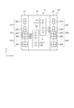
図4は、本実施形態にかかるヘッドユニット関連の構成を示す模式図であり、図3は、液滴吐出装置の動作を示す説明図である。具体的には、図4は、ヘッドユニット2における第1及び第2吐出ヘッド11,12の配列と、紫外線照射ユニット20における第1紫外線照射ユニット21と第2紫外線照射ユニット22の構成について示した模式図である。また、図3は、各液滴ドットが配置された領域に対する紫外線の照射方法を示す模式図である。
FIG. 4 is a schematic diagram illustrating a configuration related to the head unit according to the present embodiment, and FIG. 3 is an explanatory diagram illustrating an operation of the droplet discharge device. Specifically, FIG. 4 shows the arrangement of the first and second ejection heads 11 and 12 in the
図2に示すように、第1吐出ヘッド11は、複数のノズル11a〜11nを備えている。これら複数のノズル11a〜11nは、Y軸方向に列を成している。第2吐出ヘッド12は、複数のノズル12a〜12nを備えている。これら複数のノズル12a〜12nは、Y軸方向に列を成している。そして、ヘッドユニット2を走査方向(X軸方向)から透視した場合に、第1吐出ヘッド11に設けられた複数のノズル11a〜11nの一部と第2吐出ヘッド12に設けられた複数のノズル12a〜12nの一部とが重複するように、第1吐出ヘッド11と第2吐出ヘッド12とが配置されている。なお、本実施形態では、ヘッドユニット2の走査方向(X軸方向)に対して、第1吐出ヘッド11のノズル11aと第2吐出ヘッド12のノズル12aとが重複するように第1吐出ヘッド11と第2吐出ヘッド12とが配置されている。
As shown in FIG. 2, the
紫外線照射ユニット20は、第1紫外線照射ユニット21と第2紫外線照射ユニット22とを備えている。第1紫外線照射ユニット21と第2紫外線照射ユニット22は紫外線を照射する機能は同じであるが、第1紫外線照射ユニット21は、ヘッドユニット2がX軸プラス方向に移動した際に駆動し、第2紫外線照射ユニット22は、ヘッドユニット2がX軸マイナス方向に移動した際に駆動する。まず、第1紫外線照射ユニット21の構成について説明する。第1紫外線照射ユニット21は、第1紫外線照射部211と、第2紫外線照射部212と、第3紫外線照射部213とを備えている。
The
第1紫外線照射部211は、第1吐出ヘッド11から吐出された第1紫外線硬化型インクの第1液滴ドットDa(Da2〜Da4)のみが形成された第1領域101(図3参照)に対して第1硬化要素を含む紫外線を照射するものである。本実施形態にかかる第1紫外線照射部211は、第1紫外線硬化型インクに対応する第1照射強度を有する紫外線を照射する。具体的には、第1照射強度を有する発光モジュール300を備えている。そして、第1紫外線照射部211は、第1領域101に対応するように配置されている。換言すれば、第1紫外線照射部211は、第1吐出ヘッド11のノズル11b〜11n(一部重複するノズル11aを除いたノズル群)に対応して配置されている。
The first
第2紫外線照射部212は、第2吐出ヘッド12から吐出された第2紫外線硬化型インクの第2液滴ドットDb(Db2〜Db4)のみが形成された第2領域102(図3参照)に対して第2硬化要素を含む紫外線を照射するものである。本実施形態にかかる第2紫外線照射部212は、第2紫外線硬化型インクに対応する第2照射強度を有する紫外線を照射する。なお、本実施形態にかかる第2照射強度は、第1照射強度の2倍の強度である場合の構成について説明する。具体的には、第2紫外線照射部212には、第1紫外線照射部211と同じ発光モジュール300の数の2倍の数の発光モジュール300を備えている。そして、第2紫外線照射部212は、第2領域102に対応するようにY軸方向に2列となって配置されている。換言すれば、第2紫外線照射部212は、第2吐出ヘッド12のノズル12b〜12n(一部重複するノズル12aを除いたノズル群)に対応して配置されている。
The second
第3紫外線照射部213は、第1吐出ヘッド11から吐出された第1紫外線硬化型インクの第1液滴ドットDaと第2吐出ヘッド12から吐出された第2紫外線硬化型インクの第2液滴ドットDbとが混在可能なドット混在可能領域103(図3参照)における第1液滴ドットDaと第2液滴ドットDbの形成状態に応じて、第1硬化要素としての第1照射強度の紫外線と第2硬化要素としての第2照射強度の紫外線の双方、または、一方を照射するものである。具体的には、第3紫外線照射部213は、第1照射強度を照射する発光モジュールが2つ備えられている。そして、第3紫外線照射部213は、ドット混在可能領域103に対応するように配置されている。換言すれば、第3紫外線照射部213は、第1吐出ヘッド11のノズル11aと第2吐出ヘッド12のノズル12aとが重複した位置に対応して配置されている。ここで、第3紫外線照射部213では、ドット混在可能領域103における第1液滴ドットDaと第2液滴ドットDbの形成状態に応じて、2つの発光モジュール300を駆動させたり、一方の発光モジュール300を選択的に駆動させることが可能である。
The third
次に、第2紫外線照射ユニット22について説明する。第2紫外線照射ユニット22は、第1紫外線照射部221と、第2紫外線照射部222と、第3紫外線照射部223とで構成されている。なお、第1紫外線照射部221、第2紫外線照射部222及び第3紫外線照射部223の構成は、第1紫外線照射部211、第2紫外線照射部212及び第3紫外線照射部213の構成と同様なので説明を省略する。なお、第1紫外線照射部221は、第1紫外線照射ユニット21の第1紫外線照射部211に対応し、第2紫外線照射部222は、第1紫外線照射ユニット21の第2紫外線照射部212に対応し、第3紫外線照射部223は、第1紫外線照射ユニット21の第3紫外線照射部213に対応する。
Next, the second
次に、図3及び図4を参照しながら液滴吐出装置の動作について説明する。 Next, the operation of the droplet discharge device will be described with reference to FIGS.
図3(a)は、ヘッドユニット2をX軸プラス方向に移動させながら、第1及び第2吐出ヘッド11,12から液滴を吐出させ、例えば、ワークW上に第1液滴ドットDaと第2液滴ドットDbを形成したものである。第1領域101には、第1液滴ドットDa(Da2〜Da4)のみが形成され、第2領域102には第2液滴ドットDb(Db2〜Db4)のみが形成され、ドット混在可能領域103には第1液滴ドットDa1のみが形成された場合を示している。この場合、第1領域101に対して第1紫外線照射部211を駆動させ、第1照射強度を有する発光モジュール300から紫外線を照射させる。これにより、第1領域101に形成された第1液滴ドットDa(Da2〜Da4)が硬化される。
FIG. 3A shows a state in which droplets are ejected from the first and second ejection heads 11 and 12 while moving the
また、第2領域102に対して第2紫外線照射部212を駆動させ、第2照射強度として、全ての発光モジュール300を照射する。これにより、第2領域102に形成された第2液滴ドットDb(Db2〜Db4)が硬化される。
In addition, the second
また、ドット混在可能領域103に対して第3紫外線照射部213の2つの発光モジュール300のうち一つの発光モジュール300のみを選択して駆動させる。これにより、ドット混在可能領域103に形成された第1液滴ドットDa1が硬化される。
In addition, only one
図3(b)は、ヘッドユニット2をX軸プラス方向に移動させながら、第1及び第2吐出ヘッド11,12から液滴を吐出させ、例えば、ワークW上に第1液滴ドットDaと第2液滴ドットDbを形成したものである。そして、第1領域101には、第1液滴ドットDa(Da2〜Da4)のみが形成され、第2領域102には第2液滴ドットDb(Db2〜Db4)のみが形成され、ドット混在可能領域103には第2液滴ドットDb1のみが形成された場合を示している。この場合、第1領域101に対して第1紫外線照射部211を駆動させ、第1照射強度を有する発光モジュール300から紫外線を照射させる。これにより、第1領域101に形成された第1液滴ドットDa(Da2〜Da4)が硬化される。
FIG. 3B shows that the droplets are ejected from the first and second ejection heads 11 and 12 while moving the
また、第2領域102に対して第2紫外線照射部212を駆動させ、第2照射強度として全ての発光モジュール300を照射する。これにより、第2領域102に形成された第2液滴ドットDb(Db2〜Db4)が硬化される。
Further, the second
また、ドット混在可能領域103に対して第3紫外線照射部213の2つの発光モジュール300を駆動させる。これにより、ドット混在可能領域103に形成された第2液滴ドットDb1が硬化される。
In addition, the two
図3(c)は、ヘッドユニット2をX軸プラス方向に移動させながら、第1及び第2吐出ヘッド11,12から液滴を吐出させ、例えば、ワークW上に第1液滴ドットDaと第2液滴ドットDbを形成したものである。そして、第1領域101には、第1液滴ドットDa(Da2〜Da4)のみが形成され、第2領域102には第2液滴ドットDb(Db2〜Db4)のみが形成され、ドット混在可能領域103には第1液滴ドットDa1と第2液滴ドットDb1とが形成された場合を示している。この場合、第1領域101に対して第1紫外線照射部211を駆動させ、第1照射強度の発光モジュール300から紫外線を照射させる。これにより、第1領域101に形成された第1液滴ドットDa(Da2〜Da4)が硬化される。
FIG. 3C shows a case where liquid droplets are ejected from the first and second ejection heads 11 and 12 while moving the
また、第2領域102に対して第2紫外線照射部212を駆動させ、第2紫外線硬化型インクの第2照射強度の全ての発光モジュール300から紫外線を照射させる。これにより、第2領域102に形成された第2液滴ドットDb(Db2〜Db4)が硬化される。
In addition, the second
また、ドット混在可能領域103に対して第3紫外線照射部213の発光モジュール300の双方を駆動させる。これにより、ドット混在可能領域103に形成された第1液滴ドットDa1と第2液滴ドットDb1が硬化される。
Moreover, both the
以上、上記第2実施形態によれば、第1実施形態の効果に加え、以下の効果を得ることができる。 As described above, according to the second embodiment, in addition to the effects of the first embodiment, the following effects can be obtained.
(1)第1領域101に形成された第1紫外線硬化型インクの第1液滴ドットDa2〜Da4は、第1紫外線照射部211(221)から第1照射強度で照射された紫外線によって硬化される。また、第2領域102に形成された第2紫外線硬化型インクの第2液滴ドットDb2〜Db4は第2紫外線照射部212(222)から第2照射強度で照射された紫外線によって硬化される。そして、ドット混在可能領域103では、ドット混在可能領域103における第1液滴ドットDa1と第2液滴ドットDb1の形成状態に応じて、第1照射強度または第2照射強度で照射された紫外線によって硬化される。従って、第1領域101と第2領域102の境界領域におけるドット混在可能領域103に対応する第3紫外線照射部213(223)によって第1及び第2液滴ドットDa1,Db1が確実に硬化されるため、にじみ等の発生が抑制され、画像品質を向上させることができる。
(1) The first droplet dots Da2 to Da4 of the first ultraviolet curable ink formed in the
(2)ドット混在可能領域103では、第1液滴ドットDa1と第2液滴ドットDb1の形成状態に応じて、2つの発光モジュール300が選択的に駆動される。このため、消費電力を低減させ、効率的に第1液滴ドットDa1または第2液滴ドットDb1を硬化することができる。
(2) In the dot-
なお、本発明は上述した実施形態に限定されず、上述した実施形態に種々の変更や改良などを加えることが可能である。変形例を以下に述べる。 Note that the present invention is not limited to the above-described embodiment, and various modifications and improvements can be added to the above-described embodiment. A modification will be described below.
(変形例1)上記の実施形態では、2つの第1及び第2吐出ヘッド11,12の構成について説明したが、これに限定されない。例えば、3つ以上の吐出ヘッドを備えてもよい。この場合にも、ヘッドユニット2を走査方向から透視した場合に、配列される吐出ヘッド間におけるノズルの一部が重複する部分に対応するように、紫外線照射部を備えればよい。このようにしても、上記同様の効果を得ることができる。
(Modification 1) In the above embodiment, the configuration of the two first and second ejection heads 11 and 12 has been described. However, the present invention is not limited to this. For example, three or more ejection heads may be provided. Also in this case, when the
(変形例2)第1実施形態では、第1光吸収波長を発光する発光モジュール290と第2光吸収波長を発光する発光モジュール291とを備えたが、この構成に限定されない。例えば、第1紫外線照射部211と第2紫外線照射部212と第3紫外線照射部213において同じ発光モジュールを配置するとともに、第1紫外線照射部211と第2紫外線照射部212と第3紫外線照射部213に対応する波長選択フィルターを備えてもよい。このようにすれば、同様の発光モジュールを使用することができ、使用されるインク毎、吐出ヘッドの配列に応じて液滴吐出装置の使用の自由度を広げることができる。
(Modification 2) In the first embodiment, the
1…液滴吐出装置、2…ヘッドユニット、10…キャリッジ、11…第1吐出ヘッド、11a〜11n…第1吐出ヘッドのノズル、12…第2吐出ヘッド、12a〜12n…第2吐出ヘッドのノズル、20…紫外線照射ユニット、21…第1紫外線照射ユニット、22…第2紫外線照射ユニット、30…X走査軸、40…ステージ、101…第1領域、102…第2領域、103…ドット混在可能領域、211,221…第1紫外線照射部、212,222…第2紫外線照射部、213,223…第3紫外線照射部、290…第1光吸収波長を含む発光モジュール、291…第2光吸収波長を含む発光モジュール、300…第1照射強度を有する発光モジュール。
DESCRIPTION OF
Claims (4)
前記第1吐出ヘッド及び前記第2吐出ヘッドから吐出された前記第1紫外線硬化型インク及び前記第2紫外線硬化型インクに対して紫外線を照射する紫外線照射ユニットと、を備え、
前記ヘッドユニットでは、
前記ヘッドユニットを走査方向から透視した場合に、前記第1吐出ヘッドに設けられた複数のノズルの一部と前記第2吐出ヘッドに設けられた複数のノズルの一部とが重複するように、前記第1吐出ヘッドと前記第2吐出ヘッドとが配置され、
前記紫外線照射ユニットでは、
前記第1吐出ヘッドから吐出された前記第1紫外線硬化型インクの第1液滴ドットが形成された第1領域に対して第1硬化要素を含む紫外線を照射する第1紫外線照射部と、
前記第2吐出ヘッドから吐出された前記第2紫外線硬化型インクの第2液滴ドットが形成された第2領域に対して第2硬化要素を含む紫外線を照射する第2紫外線照射部と、
前記第1液滴ドットと前記第2液滴ドットとが混在可能なドット混在可能領域に対して前記第1硬化要素と前記第2硬化要素とを含む紫外線を照射する第3紫外線照射部と、が配置されたことを特徴とする液滴吐出装置。 A head unit comprising: a first ejection head that ejects a first ultraviolet curable ink; and a second ejection head that ejects a second ultraviolet curable ink;
An ultraviolet irradiation unit for irradiating ultraviolet rays to the first ultraviolet curable ink and the second ultraviolet curable ink discharged from the first discharge head and the second discharge head,
In the head unit,
When the head unit is seen through from the scanning direction, a part of the plurality of nozzles provided in the first discharge head and a part of the plurality of nozzles provided in the second discharge head overlap. The first ejection head and the second ejection head are disposed;
In the ultraviolet irradiation unit,
A first ultraviolet irradiation unit that irradiates the first region in which the first droplet dots of the first ultraviolet curable ink ejected from the first ejection head are formed with ultraviolet rays including a first curing element;
A second ultraviolet irradiation unit that irradiates the second region where the second droplet dots of the second ultraviolet curable ink ejected from the second ejection head are formed with ultraviolet rays including a second curing element;
A third ultraviolet irradiation unit that irradiates ultraviolet rays including the first curing element and the second curing element with respect to a dot-mixable region where the first droplet dots and the second droplet dots can be mixed; A liquid droplet ejection apparatus, wherein:
前記第3紫外線照射部では、
前記ドット混在可能領域における前記第1液滴ドットと前記第2液滴ドットの形成状態に応じて、前記第1硬化要素を含む紫外線と前記第2硬化要素を含む紫外線の双方、または、一方を照射することを特徴とする液滴吐出装置。 The droplet discharge device according to claim 1,
In the third ultraviolet irradiation unit,
Depending on the formation state of the first droplet dot and the second droplet dot in the dot-mixable region, both or one of the ultraviolet ray including the first curing element and the ultraviolet ray including the second curing element is used. Irradiating a droplet discharge device.
前記第1紫外線照射部では、前記第1紫外線硬化型インクの第1光吸収波長を含み、
前記第2紫外線照射部では、前記第2紫外線硬化型インクの第2光吸収波長を含み、
前記第3紫外線照射部では、前記第1光吸収波長と前記第2光吸収波長とを含むことを特徴とする液滴吐出装置。 In the liquid droplet ejection apparatus according to claim 1 or 2,
The first ultraviolet irradiation unit includes a first light absorption wavelength of the first ultraviolet curable ink,
The second ultraviolet irradiation unit includes a second light absorption wavelength of the second ultraviolet curable ink,
The third ultraviolet irradiation unit includes the first light absorption wavelength and the second light absorption wavelength.
前記第1紫外線照射部では、前記第1紫外線硬化型インクに対応する第1照射強度を含み、
前記第2紫外線照射部では、前記第2紫外線硬化型インクに対応する第2照射強度を含み、
前記第3紫外線照射部では、前記第1照射強度と前記第2照射強度を含むことを特徴とする液滴吐出装置。 In the liquid droplet ejection apparatus according to claim 1 or 2,
The first ultraviolet irradiation unit includes a first irradiation intensity corresponding to the first ultraviolet curable ink,
The second ultraviolet irradiation unit includes a second irradiation intensity corresponding to the second ultraviolet curable ink,
The third ultraviolet irradiation section includes the first irradiation intensity and the second irradiation intensity.
Priority Applications (1)
| Application Number | Priority Date | Filing Date | Title |
|---|---|---|---|
| JP2012031444A JP2013166324A (en) | 2012-02-16 | 2012-02-16 | Droplet ejection device |
Applications Claiming Priority (1)
| Application Number | Priority Date | Filing Date | Title |
|---|---|---|---|
| JP2012031444A JP2013166324A (en) | 2012-02-16 | 2012-02-16 | Droplet ejection device |
Publications (1)
| Publication Number | Publication Date |
|---|---|
| JP2013166324A true JP2013166324A (en) | 2013-08-29 |
Family
ID=49177154
Family Applications (1)
| Application Number | Title | Priority Date | Filing Date |
|---|---|---|---|
| JP2012031444A Withdrawn JP2013166324A (en) | 2012-02-16 | 2012-02-16 | Droplet ejection device |
Country Status (1)
| Country | Link |
|---|---|
| JP (1) | JP2013166324A (en) |
Cited By (1)
| Publication number | Priority date | Publication date | Assignee | Title |
|---|---|---|---|---|
| US11766876B2 (en) | 2021-05-31 | 2023-09-26 | Brother Kogyo Kabushiki Kaisha | Printer provided with irradiation device to irradiate printing object with light for curing ink deposited thereon |
Citations (8)
| Publication number | Priority date | Publication date | Assignee | Title |
|---|---|---|---|---|
| JP2005153507A (en) * | 2003-10-29 | 2005-06-16 | Konica Minolta Medical & Graphic Inc | Inkjet recording device |
| JP2006027236A (en) * | 2004-07-21 | 2006-02-02 | Seiko Epson Corp | UV irradiation equipment |
| JP2006205667A (en) * | 2005-01-31 | 2006-08-10 | Konica Minolta Medical & Graphic Inc | Inkjet recording device |
| WO2006133167A1 (en) * | 2005-06-07 | 2006-12-14 | Fusion Uv Systems, Inc. | Solid-state light sources for curing and surface modification |
| JP2008118115A (en) * | 2006-09-25 | 2008-05-22 | Avago Technologies Ecbu Ip (Singapore) Pte Ltd | Compact high-intensity LED-based light source and method for making the light source |
| JP2009126071A (en) * | 2007-11-26 | 2009-06-11 | Roland Dg Corp | Inkjet printer |
| JP2011104875A (en) * | 2009-11-18 | 2011-06-02 | Brother Industries Ltd | Inkjet recorder, inkjet recording method, and program used for inkjet recording |
| JP2012011727A (en) * | 2010-07-02 | 2012-01-19 | Canon Inc | Inkjet recording apparatus |
-
2012
- 2012-02-16 JP JP2012031444A patent/JP2013166324A/en not_active Withdrawn
Patent Citations (8)
| Publication number | Priority date | Publication date | Assignee | Title |
|---|---|---|---|---|
| JP2005153507A (en) * | 2003-10-29 | 2005-06-16 | Konica Minolta Medical & Graphic Inc | Inkjet recording device |
| JP2006027236A (en) * | 2004-07-21 | 2006-02-02 | Seiko Epson Corp | UV irradiation equipment |
| JP2006205667A (en) * | 2005-01-31 | 2006-08-10 | Konica Minolta Medical & Graphic Inc | Inkjet recording device |
| WO2006133167A1 (en) * | 2005-06-07 | 2006-12-14 | Fusion Uv Systems, Inc. | Solid-state light sources for curing and surface modification |
| JP2008118115A (en) * | 2006-09-25 | 2008-05-22 | Avago Technologies Ecbu Ip (Singapore) Pte Ltd | Compact high-intensity LED-based light source and method for making the light source |
| JP2009126071A (en) * | 2007-11-26 | 2009-06-11 | Roland Dg Corp | Inkjet printer |
| JP2011104875A (en) * | 2009-11-18 | 2011-06-02 | Brother Industries Ltd | Inkjet recorder, inkjet recording method, and program used for inkjet recording |
| JP2012011727A (en) * | 2010-07-02 | 2012-01-19 | Canon Inc | Inkjet recording apparatus |
Cited By (1)
| Publication number | Priority date | Publication date | Assignee | Title |
|---|---|---|---|---|
| US11766876B2 (en) | 2021-05-31 | 2023-09-26 | Brother Kogyo Kabushiki Kaisha | Printer provided with irradiation device to irradiate printing object with light for curing ink deposited thereon |
Similar Documents
| Publication | Publication Date | Title |
|---|---|---|
| US8545006B2 (en) | Liquid ejecting apparatus and liquid ejecting method | |
| JP5095640B2 (en) | Inkjet printer and printing method using the same | |
| JP2011062995A (en) | Liquid ejecting apparatus | |
| JP2011083915A (en) | Printing apparatus | |
| JP5668462B2 (en) | Printing apparatus and printing method | |
| JP2009226622A (en) | Inkjet printer, printing unit and printing method therefor | |
| JP2010083059A (en) | Inkjet printer and printing method using the same | |
| JP6061082B2 (en) | Recording device | |
| JP4622444B2 (en) | Inkjet recording device | |
| US8783856B2 (en) | Printing apparatus and printing method | |
| JP2016000487A (en) | Printer and printing method | |
| JP2002144553A (en) | Ink jet printer and ink curing method for the printer | |
| JP5614002B2 (en) | Printing apparatus and printing method | |
| JP5378194B2 (en) | Inkjet image forming apparatus | |
| JP5617588B2 (en) | Printing apparatus and printing method | |
| JP2010155385A (en) | Liquid ejector | |
| JP2013166324A (en) | Droplet ejection device | |
| JP5790098B2 (en) | Liquid ejection apparatus and liquid ejection method | |
| JP2012045909A (en) | Image forming apparatus, and image forming method | |
| JP5216156B2 (en) | Inkjet printer, printing unit and printing method therefor | |
| JP5682753B2 (en) | Recording device | |
| JP2012106392A (en) | Drawing apparatus and method of controlling the same | |
| JP2014015054A (en) | Printing apparatus | |
| JP2012121197A (en) | Printer and printing method | |
| JP2011062996A (en) | Liquid ejecting apparatus |
Legal Events
| Date | Code | Title | Description |
|---|---|---|---|
| RD04 | Notification of resignation of power of attorney |
Free format text: JAPANESE INTERMEDIATE CODE: A7424 Effective date: 20150107 |
|
| A621 | Written request for application examination |
Free format text: JAPANESE INTERMEDIATE CODE: A621 Effective date: 20150119 |
|
| A977 | Report on retrieval |
Free format text: JAPANESE INTERMEDIATE CODE: A971007 Effective date: 20151118 |
|
| A131 | Notification of reasons for refusal |
Free format text: JAPANESE INTERMEDIATE CODE: A131 Effective date: 20151201 |
|
| A761 | Written withdrawal of application |
Free format text: JAPANESE INTERMEDIATE CODE: A761 Effective date: 20160126 |