JP2013156801A5 - - Google Patents
Download PDFInfo
- Publication number
- JP2013156801A5 JP2013156801A5 JP2012016266A JP2012016266A JP2013156801A5 JP 2013156801 A5 JP2013156801 A5 JP 2013156801A5 JP 2012016266 A JP2012016266 A JP 2012016266A JP 2012016266 A JP2012016266 A JP 2012016266A JP 2013156801 A5 JP2013156801 A5 JP 2013156801A5
- Authority
- JP
- Japan
- Prior art keywords
- flow rate
- gas
- pressure
- control unit
- flow
- Prior art date
- Legal status (The legal status is an assumption and is not a legal conclusion. Google has not performed a legal analysis and makes no representation as to the accuracy of the status listed.)
- Granted
Links
- 238000000034 method Methods 0.000 description 14
- 238000004519 manufacturing process Methods 0.000 description 5
- 239000004065 semiconductor Substances 0.000 description 3
- 229910004682 ON-OFF Inorganic materials 0.000 description 1
- 239000000126 substance Substances 0.000 description 1
- 238000011144 upstream manufacturing Methods 0.000 description 1
Images


Description
また、当該圧力式流量制御装置に於いては、圧力検出器P及び温度検出器Tからの検出値がディジタル信号に変換されて温度補正・流量演算回路CDaへ入力され、ここで検出圧力の温度補正及び流量演算が行われたあと、流量演算値Qtが比較回路CDbへ入力される。一方、設定流量入力信号Qsが端子Inから入力され、入出力回路CDcでディジタル値に変換されたあと比較回路CDbへ入力され、ここで前記温度補正・流量演算回路CDaからの流量演算値Qtと比較される。そして、設定流量入力信号Qsが流量演算値Qtより大きい場合には、コントロール弁CVの駆動部へ制御信号Pdが出力され、コントロール弁CVがその駆動機構CVaを介して開放方向へ駆動される。即ち、設定流量入力信号Qsと演算流量値Qtとの差(Qs−Qt)が零となるまで開弁方向へ駆動される。 In the pressure type flow rate control device, the detected values from the pressure detector P and the temperature detector T are converted into digital signals and input to the temperature correction / flow rate calculation circuit CDa, where the temperature of the detected pressure is detected. After the correction and the flow rate calculation are performed, the flow rate calculation value Qt is input to the comparison circuit CDb. On the other hand, the set flow rate input signal Qs is input from the terminal In, converted to a digital value by the input / output circuit CDc, and then input to the comparison circuit CDb, where the flow rate calculation value Qt from the temperature correction / flow rate calculation circuit CDa is To be compared. When the set flow rate input signal Qs is larger than the flow rate calculation value Qt, the control signal Pd is output to the drive portion of the control valve CV, and the control valve CV is driven in the opening direction via the drive mechanism CVa. That is, the valve is driven in the valve opening direction until the difference (Qs−Qt) between the set flow rate input signal Qs and the calculated flow rate value Qt becomes zero.
また、制御部ACQ及び自動調圧器ACPの制御系が所謂フィードバック制御を採用しておらず、その結果、開閉弁V1、V2の開閉作動によって生ずる一次側圧力P1の変動を自動調圧器ACPが迅速に調整することが困難となり、流量Q1(又は流量Q 2 )に変動を生じ易いという問題がある。 In addition, the control system of the control unit ACQ and the automatic pressure regulator ACP does not employ so-called feedback control, and as a result, the automatic pressure regulator changes fluctuations in the primary pressure P 1 caused by the opening / closing operation of the on-off valves V 1 and V 2. There is a problem that it is difficult to adjust the ACP quickly, and the flow rate Q 1 (or the flow rate Q 2 ) is likely to fluctuate.
本願発明は、従前の圧力式流量制御装置を用いたガス分流供給装置に於ける上述の如き問題、即ち(イ)各ガス供給ライン(各分流ライン)に圧力式流量制御装置を設ける場合には、ガス供給装置の小型化、低コスト化が図り難いこと、また(ロ)ガス供給源側に設けた自動調圧器により各オリフィスの1次側圧力P1を調整し、各オリフィスを通して圧力P1に比例した各分流ガス流量Q1、Q2を供給する場合には、ガス供給装置の組立製造に手数が掛かって装置の小型、コンパクト化が困難なこと、何れかの分流路の開閉時に
オリフィス1次側圧力P1に変動が生じて他の分流路の分流量が変動し易いこと、オリフィス1次側圧力P1と2次側圧力P2の比P1/P2が臨界膨張条件外の値(例えばO2やN2の場合には約2以下)になると分流流量Q1、Q2の高精度な制御が困難になること等の問題を解決せんとするものであり、構造の簡素化と小型を図ったガス分流供給装置でもって、同じプロセスを行う多数のプロセスチャンバへプロセスガスを経済的にしかも高精度な流量制御を行いつつ分流供給することができると共に、圧力式流量制御装置と熱式流量制御装置とを有機的に一体化することにより、臨界膨張条件を外れた状態下に於いても高精度なガス分流供給ができ、且つ、必要に応じて任意に供給中のプロセスガスの実流量監視を行えるようにした半導体製造装置のガス分流供給装置を提供するものである。
The present invention relates to the above-mentioned problem in the gas shunt supply device using the conventional pressure flow control device, that is, (i) when the pressure flow control device is provided in each gas supply line (each shunt line). miniaturization of the gas supply apparatus, it hardly cost reduction aims, also (ii) to adjust the primary pressure P 1 of the orifice by an automatic pressure controller provided in the gas supply side, the pressure P 1 through each orifice When supplying the diverted gas flow rates Q 1 and Q 2 in proportion to each other, it is difficult to reduce the size and size of the apparatus due to the time required for assembly and manufacture of the gas supply apparatus. Fluctuation occurs in the primary side pressure P 1 and the flow rate of the other shunt flow path is likely to fluctuate, and the ratio P 1 / P 2 between the orifice primary side pressure P 1 and the secondary side pressure P 2 is outside the critical expansion condition. of when the value of (e.g., O 2 and N 2 is from about 2 Below) in the shunt flow rate Q 1, are those precise control Q 2 'is St solve problems such be difficult, with a gas branched flow supplying apparatus achieves a simplified structure and small size, the same Process gas can be supplied to multiple process chambers performing processes economically and with high precision flow rate control, and the pressure flow rate control device and thermal flow rate control device are organically integrated. by, even in under disengaged critical expansion conditions can accurately gas shunt supply, and, a semiconductor manufacturing apparatus so as to perform the actual flow rate monitoring of the process gas in the optionally supplied as needed A gas diversion supply device is provided.
請求項2の発明は、プロセスガス入口11に接続した圧力式流量制御部1aを構成するコントロール弁3と,コントロール弁3の下流側に接続した熱式質量流量制御部1bを構成する熱式流量センサ2と,熱式流量センサ2の下流側に連通するガス供給主管8と,ガス供給主管8の下流側に並列状に接続した複数の分岐管路9a、9nと,各分岐管路9a、9nに介設した分岐管路開閉弁10a、10nと,前記コントロール弁3の下流側のガス供給主管8に設けたオリフィス6と,前記コントロール弁3とオリフィス6の間のプロセスガス通路近傍に設けた温度センサ4と,前記コントロール弁3とオリフィス6の間のプロセスガス通路に設けた圧力センサ5と,前記分岐管路9a、9nの出口側に設けた分流ガス出口11a、11nと,前記圧力センサ5からの圧力信号及び温度センサ4からの温度信号が入力され、前記オリフィス6を流通するプロセスガスの総流量Qを演算すると共に、演算した流量値と設定流量値との差が減少する方向に前記コントロール弁3を開閉作動させる制御信号Pdを弁駆動部3aへ出力すると共に、前記分岐管路開閉弁10a、10nへ各分岐管路開閉弁10a、10nを夫々一定時間だけ順次開放した後これを閉鎖する開閉制御信号Oda、Odnを出力する圧力式流量演算制御部7a及び前記熱式流量センサ2からの流量信号2cが入力され当該流量信号2cからガス供給主管8を流通するプロセスガスの総流量Qを演算表示する熱式流量演算制御部7bとからなる演算制御部7と,を具備し、前記オリフィス6を流通するプロセスガス流が臨界膨張条件を満たすガス流のときは前記圧力式流量制御部1aによりプロセスガスの流量制御を、また、プロセスガス流が臨界膨張条件を満たさないガス流のときは前記熱式質量流量制御部1bによりプロセスガスの流量制御を行うと共に、前記分岐管路開閉弁10a、10nの開閉によりプロセスガスを分流供給するようにしたことを発明の基本構成とするものである。
The invention according to
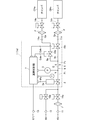
図3は、本発明に係る半導体製造装置のガス分流供給装置の第2実施形態に係る構成説明図であり、当該ガス分流供給装置1は、圧力式流量制御部1aと熱式流量制御部1bの二つの部分から構成されている。
FIG. 3 is a configuration explanatory view according to a second embodiment of the gas shunt supply device of the semiconductor manufacturing apparatus according to the present invention. The gas
即ち、当該ガス分流供給装置1は、熱式流量制御部1bを形成する熱式流量センサ部2と、圧力式流量制御部1aを形成するコントロール弁3、温度センサ4、圧力センサ5、オリフィス6と、圧力式流量制御部1aの演算制御部7a及び熱式流量制御部1bの演算制御部7bを形成する演算制御部7と、ガス供給主管8等から構成されており、オリフィス6を流通するガスが臨界膨張条件下にある場合、例えばO2やN2ガスであってオリフィス6の上流側圧力P1と下流側圧力P2とがP1/P2>2の関係にある場合には、圧力式流量制御部1aによって総流量Qの流量制御を行いつつ、圧力式流量制御部1aからの開閉制御信号Oda、Odnによって各分岐管路開閉弁10a、10nの開閉が、図1のタイムチャートTMに示されているように、夫々一定時間だけ順次開放された後閉鎖される。
That is, the gas
また、オリフィス6を流通するガスが臨界膨張条件を外れた状態にある場合には、熱式流量制御部1bによってプロセスガス流量Qnの流量制御を行いつつ、各分岐管路開閉弁10a、10nが、上記と同様に図1のタイムチャートTMに従って夫々一定時間だけ順次開放された後閉鎖されることにより、流量Qa・Qnの分流ガスが各チャンバCHa、CHnへ供給されて行く。
Further, when the gas flowing through the
本発明は半導体製造装置のガス分流供給設備としてのみならず、化学品製造装置等のガス分流供給設備にも広く適用できるものである。 The present invention can be widely applied not only as a gas shunt supply facility for a semiconductor manufacturing apparatus but also to a gas shunt supply facility for a chemical manufacturing apparatus or the like .
Priority Applications (6)
| Application Number | Priority Date | Filing Date | Title |
|---|---|---|---|
| JP2012016266A JP5754853B2 (en) | 2012-01-30 | 2012-01-30 | Gas shunt supply device for semiconductor manufacturing equipment |
| US14/375,758 US20140373935A1 (en) | 2012-01-30 | 2012-10-17 | Gas branched flow supplying apparatus for semiconductor manufacturing equipment |
| CN201280068410.9A CN104081304B (en) | 2012-01-30 | 2012-10-17 | The gas distribution feedway of semiconductor- fabricating device |
| KR1020147018214A KR101677971B1 (en) | 2012-01-30 | 2012-10-17 | Gas split-flow supply device for semiconductor production device |
| PCT/JP2012/006626 WO2013114486A1 (en) | 2012-01-30 | 2012-10-17 | Gas split-flow supply device for semiconductor production device |
| TW101140130A TWI505386B (en) | 2012-01-30 | 2012-10-30 | And a gas shunt supply device for a semiconductor manufacturing apparatus |
Applications Claiming Priority (1)
| Application Number | Priority Date | Filing Date | Title |
|---|---|---|---|
| JP2012016266A JP5754853B2 (en) | 2012-01-30 | 2012-01-30 | Gas shunt supply device for semiconductor manufacturing equipment |
Publications (3)
| Publication Number | Publication Date |
|---|---|
| JP2013156801A JP2013156801A (en) | 2013-08-15 |
| JP2013156801A5 true JP2013156801A5 (en) | 2014-12-18 |
| JP5754853B2 JP5754853B2 (en) | 2015-07-29 |
Family
ID=48904576
Family Applications (1)
| Application Number | Title | Priority Date | Filing Date |
|---|---|---|---|
| JP2012016266A Active JP5754853B2 (en) | 2012-01-30 | 2012-01-30 | Gas shunt supply device for semiconductor manufacturing equipment |
Country Status (6)
| Country | Link |
|---|---|
| US (1) | US20140373935A1 (en) |
| JP (1) | JP5754853B2 (en) |
| KR (1) | KR101677971B1 (en) |
| CN (1) | CN104081304B (en) |
| TW (1) | TWI505386B (en) |
| WO (1) | WO2013114486A1 (en) |
Families Citing this family (17)
| Publication number | Priority date | Publication date | Assignee | Title |
|---|---|---|---|---|
| JP6246606B2 (en) * | 2014-01-31 | 2017-12-13 | 株式会社Screenホールディングス | Substrate processing equipment |
| CN105551995A (en) * | 2014-10-30 | 2016-05-04 | 北京北方微电子基地设备工艺研究中心有限责任公司 | Inflation air channel of vacuum chambers and semiconductor processing equipment |
| US20160363500A1 (en) * | 2015-01-23 | 2016-12-15 | Innovative Pressure Testing, Llc | System and method for improving pressure test efficiency |
| US9904299B2 (en) * | 2015-04-08 | 2018-02-27 | Tokyo Electron Limited | Gas supply control method |
| JP6516666B2 (en) * | 2015-04-08 | 2019-05-22 | 東京エレクトロン株式会社 | Gas supply control method |
| US10768641B2 (en) * | 2015-08-26 | 2020-09-08 | Fujikin Incorporated | Flow dividing system |
| JP6748586B2 (en) * | 2016-07-11 | 2020-09-02 | 東京エレクトロン株式会社 | Gas supply system, substrate processing system and gas supply method |
| CN106155120A (en) * | 2016-09-08 | 2016-11-23 | 中国航空工业集团公司西安飞机设计研究所 | A kind of multichannel flow allocation method and multichannel flow distributing system |
| JP7245600B2 (en) * | 2016-12-15 | 2023-03-24 | 株式会社堀場エステック | Flow control device and program for flow control device |
| KR102162046B1 (en) * | 2017-02-10 | 2020-10-06 | 가부시키가이샤 후지킨 | Flow measurement method and flow measurement device |
| CN110462269B (en) * | 2017-06-22 | 2021-06-15 | 株式会社富士金 | Flow rate control device and flow rate control method for flow rate control device |
| KR102250969B1 (en) * | 2017-07-31 | 2021-05-12 | 가부시키가이샤 후지킨 | Fluid control system and flow measurement method |
| JP7164938B2 (en) * | 2017-07-31 | 2022-11-02 | 株式会社堀場エステック | Flow control device, flow control method, and program for flow control device |
| KR102421590B1 (en) * | 2018-04-27 | 2022-07-15 | 가부시키가이샤 후지킨 | Flow control method and flow control device |
| CN111986971A (en) * | 2019-05-23 | 2020-11-24 | 北京北方华创微电子装备有限公司 | Microwave source air inlet device and semiconductor process equipment |
| CN112460608B (en) * | 2020-11-27 | 2022-09-16 | 潮州深能环保有限公司 | Sludge pipeline conveying system and method for waste incineration power plant |
| CN113857147A (en) * | 2021-09-13 | 2021-12-31 | 安徽万维克林精密装备有限公司 | Multifunctional automatic purging device |
Family Cites Families (27)
| Publication number | Priority date | Publication date | Assignee | Title |
|---|---|---|---|---|
| JP3025395B2 (en) * | 1993-07-12 | 2000-03-27 | 株式会社山武 | Flow control valve device |
| JP3291161B2 (en) * | 1995-06-12 | 2002-06-10 | 株式会社フジキン | Pressure type flow controller |
| US5865205A (en) * | 1997-04-17 | 1999-02-02 | Applied Materials, Inc. | Dynamic gas flow controller |
| JP3586075B2 (en) * | 1997-08-15 | 2004-11-10 | 忠弘 大見 | Pressure type flow controller |
| JPH11212653A (en) * | 1998-01-21 | 1999-08-06 | Fujikin Inc | Fluid supplier |
| JP3522535B2 (en) * | 1998-05-29 | 2004-04-26 | 忠弘 大見 | Gas supply equipment equipped with pressure type flow controller |
| CN1114847C (en) * | 1998-08-24 | 2003-07-16 | 株式会社富士金 | Method for detecting plugging of pressure flow-rate controller and sensor used therefor |
| EP1096351A4 (en) * | 1999-04-16 | 2004-12-15 | Fujikin Kk | Parallel bypass type fluid feeding device, and method and device for controlling fluid variable type pressure system flow rate used for the device |
| JP3626874B2 (en) | 1999-04-16 | 2005-03-09 | 忠弘 大見 | Parallel shunt type fluid supply device |
| US6210482B1 (en) * | 1999-04-22 | 2001-04-03 | Fujikin Incorporated | Apparatus for feeding gases for use in semiconductor manufacturing |
| US6119710A (en) * | 1999-05-26 | 2000-09-19 | Cyber Instrument Technologies Llc | Method for wide range gas flow system with real time flow measurement and correction |
| US6564824B2 (en) * | 2001-04-13 | 2003-05-20 | Flowmatrix, Inc. | Mass flow meter systems and methods |
| JP3604354B2 (en) * | 2001-06-13 | 2004-12-22 | Smc株式会社 | Mass flow measurement method and mass flow controller |
| JP4197648B2 (en) * | 2001-10-18 | 2008-12-17 | シーケーディ株式会社 | Pulse shot type flow control device and pulse shot type flow control method |
| JP4082901B2 (en) * | 2001-12-28 | 2008-04-30 | 忠弘 大見 | Pressure sensor, pressure control device, and temperature drift correction device for pressure flow control device |
| US6766260B2 (en) * | 2002-01-04 | 2004-07-20 | Mks Instruments, Inc. | Mass flow ratio system and method |
| JP2003323217A (en) | 2002-05-01 | 2003-11-14 | Stec Inc | System for controlling flow rate |
| JP4137666B2 (en) * | 2003-02-17 | 2008-08-20 | 株式会社堀場エステック | Mass flow controller |
| JP2004280788A (en) * | 2003-02-28 | 2004-10-07 | Advanced Energy Japan Kk | System for dividing gas |
| JP4195837B2 (en) * | 2003-06-20 | 2008-12-17 | 東京エレクトロン株式会社 | Gas diversion supply apparatus and gas diversion supply method |
| JP4399227B2 (en) * | 2003-10-06 | 2010-01-13 | 株式会社フジキン | Chamber internal pressure control device and internal pressure controlled chamber |
| JP4856905B2 (en) * | 2005-06-27 | 2012-01-18 | 国立大学法人東北大学 | Flow rate variable type flow control device |
| JP4814706B2 (en) | 2006-06-27 | 2011-11-16 | 株式会社フジキン | Flow ratio variable type fluid supply device |
| JP5459895B2 (en) * | 2007-10-15 | 2014-04-02 | Ckd株式会社 | Gas shunt supply unit |
| JP2010169657A (en) * | 2008-12-25 | 2010-08-05 | Horiba Stec Co Ltd | Mass flow meter and mass flow controller |
| JP5562712B2 (en) * | 2010-04-30 | 2014-07-30 | 東京エレクトロン株式会社 | Gas supply equipment for semiconductor manufacturing equipment |
| JP5430621B2 (en) * | 2011-08-10 | 2014-03-05 | Ckd株式会社 | Gas flow verification system and gas flow verification unit |
-
2012
- 2012-01-30 JP JP2012016266A patent/JP5754853B2/en active Active
- 2012-10-17 US US14/375,758 patent/US20140373935A1/en not_active Abandoned
- 2012-10-17 WO PCT/JP2012/006626 patent/WO2013114486A1/en active Application Filing
- 2012-10-17 KR KR1020147018214A patent/KR101677971B1/en active IP Right Grant
- 2012-10-17 CN CN201280068410.9A patent/CN104081304B/en not_active Expired - Fee Related
- 2012-10-30 TW TW101140130A patent/TWI505386B/en active
Similar Documents
| Publication | Publication Date | Title |
|---|---|---|
| JP2013156801A5 (en) | ||
| JP4642115B2 (en) | Flow rate ratio controller | |
| JP5754853B2 (en) | Gas shunt supply device for semiconductor manufacturing equipment | |
| JP5665794B2 (en) | Gas shunt supply device for semiconductor manufacturing equipment | |
| JP5430621B2 (en) | Gas flow verification system and gas flow verification unit | |
| JP4585035B2 (en) | Flow rate ratio controller | |
| TWI470187B (en) | Flow measurement device for flow control device for gas supply device and flow measurement method | |
| TWI497248B (en) | A gas split supply device and a gas diversion supply method using the same | |
| TWI451220B (en) | Method and apparatus for pressure and mix ratio control | |
| KR101707877B1 (en) | Flow volume control device equipped with flow rate monitor | |
| JP5058358B2 (en) | Diagnostic mechanism | |
| JP5091821B2 (en) | Mass flow controller | |
| CN110908414A (en) | System and method for controlling temperature of pipeline confluence liquid | |
| JP2004280689A (en) | Mass flow controller | |
| JP5394526B2 (en) | Calorie measuring device | |
| JP2015059740A (en) | Fluid supply facility |