JP2013146122A - Drive device, method for driving piezoelectric motor, electronic component transfer device, electronic component inspection device, robot hand, and robot - Google Patents
Drive device, method for driving piezoelectric motor, electronic component transfer device, electronic component inspection device, robot hand, and robot Download PDFInfo
- Publication number
- JP2013146122A JP2013146122A JP2012004816A JP2012004816A JP2013146122A JP 2013146122 A JP2013146122 A JP 2013146122A JP 2012004816 A JP2012004816 A JP 2012004816A JP 2012004816 A JP2012004816 A JP 2012004816A JP 2013146122 A JP2013146122 A JP 2013146122A
- Authority
- JP
- Japan
- Prior art keywords
- vibration
- unit
- driven
- state
- driving
- Prior art date
- Legal status (The legal status is an assumption and is not a legal conclusion. Google has not performed a legal analysis and makes no representation as to the accuracy of the status listed.)
- Granted
Links
Images


Abstract
Description
本発明は、駆動装置、圧電モーターの駆動方法、電子部品搬送装置、電子部品検査装置、ロボットハンド、及びロボットに関する。 The present invention relates to a driving device, a piezoelectric motor driving method, an electronic component transport device, an electronic component inspection device, a robot hand, and a robot.
圧電素子を含む振動部で生じる振動を摩擦力で被駆動部に伝達して駆動する圧電モーターが知られている(例えば、特許文献1参照)。圧電モーターでは、圧電モーターが駆動されない非駆動状態において、振動部が被駆動部に接触したままとなるため、振動部と被駆動部との間の摩擦力により被駆動部の位置が保持される。圧電モーターは、このような保持力を有することにより、電磁モーターやパルスモーターのように、被駆動部の位置を保持するためのブレーキ機構を必要としない。 2. Description of the Related Art A piezoelectric motor that drives a vibration generated in a vibration part including a piezoelectric element by transmitting the vibration to a driven part with a frictional force is known (for example, see Patent Document 1). In the piezoelectric motor, the vibration part remains in contact with the driven part in the non-driven state where the piezoelectric motor is not driven, so that the position of the driven part is maintained by the frictional force between the vibration part and the driven part. . Since the piezoelectric motor has such a holding force, it does not require a brake mechanism for holding the position of the driven part, unlike an electromagnetic motor or a pulse motor.
圧電モーターを駆動して可動部を所定の位置に移動させる装置、例えば、電子部品検査装置やロボット等の場合、圧電モーターの非駆動状態においては、上述の保持力により可動部の位置が保持される。しかしながら、圧電モーターの非駆動状態において、手動で可動部を動かして所定の位置に位置合わせしたい場合は、その保持力が妨げとなり位置合わせを行うことが困難であるという課題があった。 In the case of an apparatus that drives the piezoelectric motor to move the movable part to a predetermined position, such as an electronic component inspection apparatus or a robot, the position of the movable part is held by the holding force described above when the piezoelectric motor is not driven. The However, in the non-driven state of the piezoelectric motor, if it is desired to manually move the movable part to align it with a predetermined position, there is a problem that it is difficult to perform alignment because of the holding force.
本発明は、上述の課題の少なくとも一部を解決するためになされたものであり、以下の形態又は適用例として実現することが可能である。 SUMMARY An advantage of some aspects of the invention is to solve at least a part of the problems described above, and the invention can be implemented as the following forms or application examples.
[適用例1]本適用例に係る駆動装置は、可動部と、縦振動及び屈曲振動を発生する振動部と前記振動部の前記屈曲振動により駆動される被駆動部とを有し、前記振動部が前記被駆動部を駆動することにより前記可動部を移動させる圧電モーターと、前記振動部に駆動信号を供給する駆動信号供給部と、を備え、前記振動部に前記駆動信号を供給しない非駆動状態から、前記振動部に前記縦振動を発生させる第1の状態に移行することが可能であることを特徴とする。 Application Example 1 A driving apparatus according to this application example includes a movable part, a vibration part that generates longitudinal vibration and bending vibration, and a driven part that is driven by the bending vibration of the vibration part. A piezoelectric motor that moves the movable part by driving the driven part, and a drive signal supply part that supplies a drive signal to the vibration part, and does not supply the drive signal to the vibration part. It is possible to shift from a driving state to a first state in which the longitudinal vibration is generated in the vibration unit.
この構成によれば、駆動装置は、圧電モーターの振動部に駆動信号を供給しない非駆動状態から振動部に縦振動を発生させる第1の状態に移行することができる。第1の状態では、振動部が縦振動することにより、振動部と被駆動部との接触が断続的となる。そのため、第1の状態では、非駆動状態に比べて被駆動部の位置を保持する保持力が低下するので、可動部に外力が加えられた場合に可動部が移動し易くなる。これにより、可動部を手動で動かして容易に位置合わせを行うことが可能な駆動装置を提供できる。 According to this configuration, the driving device can shift from a non-driving state in which a driving signal is not supplied to the vibrating portion of the piezoelectric motor to a first state in which longitudinal vibration is generated in the vibrating portion. In the first state, the vibration part is vibrated longitudinally, whereby contact between the vibration part and the driven part becomes intermittent. For this reason, in the first state, the holding force for holding the position of the driven portion is lower than in the non-driven state, so that the movable portion is easily moved when an external force is applied to the movable portion. As a result, it is possible to provide a drive device that can be easily positioned by manually moving the movable part.
[適用例2]上記適用例に係る駆動装置であって、前記駆動信号供給部は、前記第1の状態において前記振動部に第1の電圧値の前記駆動信号を供給し、前記第1の電圧値は、前記振動部に前記屈曲振動を発生させる第2の状態において前記被駆動部が駆動され移動を開始する前記駆動信号の電圧値である第2の電圧値よりも低いことが好ましい。 Application Example 2 In the driving device according to the application example, the drive signal supply unit supplies the drive signal having a first voltage value to the vibration unit in the first state, and The voltage value is preferably lower than a second voltage value that is a voltage value of the drive signal that drives and starts the movement of the driven part in the second state in which the vibration part generates the bending vibration.
この構成によれば、駆動装置では、第1の状態に移行した場合に駆動信号供給部が振動部に供給する駆動信号の第1の電圧値は、振動部に屈曲振動を発生させる第2の状態において被駆動部が駆動され移動を開始する第2の電圧値よりも低い。そのため、第1の状態において駆動信号の電圧値を上昇させると被駆動部が駆動され移動してしまう場合でも、駆動信号の電圧値を第2の電圧値よりも低い第1の電圧値とすることで、被駆動部が移動することを抑止できる。これにより、可動部の位置合わせをより確実に行うことができる。 According to this configuration, in the drive device, the first voltage value of the drive signal supplied to the vibration part by the drive signal supply unit when the drive signal is shifted to the first state is the second voltage value that causes the vibration part to generate bending vibration. It is lower than the second voltage value at which the driven part is driven and starts moving in the state. Therefore, even if the driven part is driven and moved when the voltage value of the drive signal is increased in the first state, the voltage value of the drive signal is set to the first voltage value lower than the second voltage value. Thus, the movement of the driven part can be suppressed. Thereby, alignment of a movable part can be performed more reliably.
[適用例3]上記適用例に係る駆動装置であって、前記可動部に加えられた外力を検知する第1の検知部を備え、前記非駆動状態において前記第1の検知部が前記可動部に加えられた外力を検知した場合に、前記第1の状態に移行することが好ましい。 Application Example 3 The driving apparatus according to the application example described above, further including a first detection unit that detects an external force applied to the movable unit, and the first detection unit is the movable unit in the non-driven state. It is preferable to shift to the first state when an external force applied to is detected.
この構成によれば、駆動装置は、非駆動状態において第1の検知部が可動部に加えられた外力を検知した場合に、第1の状態に移行して保持力を低下させる。そのため、例えば位置合わせを行う操作者が、可動部を動かそうとする力を加えることで、可動部を手動で動かして位置合わせできる状態に切り替えることができる。 According to this configuration, when the first detection unit detects an external force applied to the movable unit in the non-driving state, the driving device shifts to the first state and decreases the holding force. Therefore, for example, when an operator who performs alignment applies a force to move the movable portion, the movable portion can be manually moved to be switched to a state where the alignment can be performed.
[適用例4]上記適用例に係る駆動装置であって、前記被駆動部に加えられた外力を検知する第2の検知部を備え、前記第1の状態において前記第2の検知部が前記被駆動部に加えられた外力を検知した場合に、前記駆動信号の電圧値を前記第1の状態に移行したときの電圧値よりも高くすることが好ましい。 Application Example 4 The driving apparatus according to the application example described above, further including a second detection unit that detects an external force applied to the driven unit, and in the first state, the second detection unit is When an external force applied to the driven part is detected, it is preferable that the voltage value of the drive signal is higher than the voltage value when the first signal is shifted to the first state.
この構成によれば、駆動装置は、第1の状態において第2の検知部が可動部に加えられた外力を検知した場合に、第1の状態に移行したときよりも駆動信号の電圧値を高くして保持力を低下させる。そのため、弱い力でも容易に可動部を動かして位置合わせを行うことができる。 According to this configuration, when the second detection unit detects an external force applied to the movable unit in the first state, the drive device sets the voltage value of the drive signal more than when the state transitions to the first state. Increase to decrease retention. Therefore, even with weak force, the movable part can be easily moved for alignment.
[適用例5]上記適用例に係る駆動装置であって、前記可動部に加えられた外力を検知する第1の検知部と、前記被駆動部に加えられた外力を検知する第2の検知部と、を備え、前記非駆動状態において前記第1の検知部が前記可動部に加えられた外力を検知した場合に前記第1の状態に移行し、前記第1の状態において前記第2の検知部が前記被駆動部に加えられた外力を検知した場合に、前記駆動信号の電圧値を前記第1の状態に移行したときの電圧値よりも高くすることが好ましい。 Application Example 5 In the driving apparatus according to the application example described above, a first detection unit that detects an external force applied to the movable unit and a second detection that detects an external force applied to the driven unit. And when the first detection unit detects an external force applied to the movable unit in the non-driven state, the second state shifts to the first state. When the detection unit detects an external force applied to the driven portion, it is preferable that the voltage value of the drive signal is higher than the voltage value when the first state is shifted to.
この構成によれば、駆動装置は、非駆動状態において第1の検知部が外力を検知した場合に第1の状態に移行して保持力を低下させ、第1の状態において第2の検知部が外力を検知した場合に、第1の状態に移行したときよりも保持力をさらに低下させる。そのため、予め保持力を低下させておかなくてもよく、また、2つの検知部のそれぞれで外力を検知して2段階で保持力を低下させることができる。これにより、不用意な接触や誤操作による可動部の移動を抑えて、確実かつ容易に可動部の位置合わせを行うことができる。また、第1の状態に移行するまでの待機中の消費電力を抑えることができる。 According to this configuration, when the first detection unit detects an external force in the non-driving state, the driving device shifts to the first state and decreases the holding force, and the second detection unit in the first state. When the external force is detected, the holding force is further reduced as compared with the case of shifting to the first state. Therefore, the holding force does not need to be reduced in advance, and the holding force can be reduced in two stages by detecting the external force with each of the two detection units. Thereby, the movement of the movable part due to inadvertent contact or erroneous operation can be suppressed, and the movable part can be aligned reliably and easily. In addition, power consumption during standby until the shift to the first state can be suppressed.
[適用例6]上記適用例に係る駆動装置であって、前記非駆動状態において前記可動部に加えられた外力を検知することで前記第1の状態に移行する場合と、前記第1の状態において前記被駆動部に加えられた外力を検知することで前記駆動信号の電圧値を前記第1の状態に移行したときの電圧値よりも高くする場合と、前記非駆動状態において前記可動部に加えられた外力を検知することで前記第1の状態に移行し、かつ、前記第1の状態において前記被駆動部に加えられた外力を検知することで前記駆動信号の電圧値を前記第1の状態に移行したときの電圧値よりも高くする場合と、前記可動部に加えられた外力及び前記被駆動部に加えられた外力を検知しない場合と、のいずれかに切り替える切り替え部を備えることが好ましい。 Application Example 6 In the driving device according to the application example described above, when the external state applied to the movable part in the non-driving state is detected, the first state is changed, and the first state is detected. In the case where the voltage value of the driving signal is made higher than the voltage value when the driving signal is shifted to the first state by detecting the external force applied to the driven portion in the non-driving state, By detecting the applied external force, the state shifts to the first state, and in the first state, the external force applied to the driven part is detected, and the voltage value of the drive signal is set to the first state. A switching unit that switches to one of a case where the voltage value is higher than the voltage value at the time of transition to the state and a case where the external force applied to the movable portion and the external force applied to the driven portion are not detected. Is preferred.
この構成によれば、2つの検知部のいずれか一方で外力を検知して1段階で保持力を低下させる場合と、2つの検知部の双方で外力を検知して2段階で保持力を低下させる場合と、2つの検知部のいずれによっても外力を検知しない場合と、を切り替えることができる。そのため、可動部の構成や、位置合わせ作業の目的、内容等に応じて適宜切り替えることにより、様々な状況に対応して位置合わせ作業を適切に行うことができる。また、位置合わせ作業を行わない場合は、外力が加えられても第1の状態に移行しないようにすることができる。 According to this configuration, the external force is detected by one of the two detection units and the holding force is reduced in one step, and the external force is detected by both the two detection units and the holding force is reduced in two steps. The case where the external force is not detected by either of the two detection units can be switched. Therefore, the alignment work can be appropriately performed corresponding to various situations by appropriately switching according to the configuration of the movable part, the purpose and contents of the alignment work. Further, when the alignment operation is not performed, it is possible to prevent the shift to the first state even when an external force is applied.
[適用例7]本適用例に係る圧電モーターの駆動方法は、可動部と、縦振動及び屈曲振動を発生する振動部と前記振動部の前記屈曲振動により駆動される被駆動部とを有し、前記振動部が前記被駆動部を駆動することにより前記可動部を移動させる圧電モーターと、前記振動部に駆動信号を供給する駆動信号供給部と、前記可動部に加えられた外力を検知する第1の検知部と、を備えた圧電モーターの駆動方法であって、前記振動部に前記駆動信号を供給しない非駆動状態において前記第1の検知部が前記可動部に加えられた外力を検知した場合に、前記振動部に前記縦振動を発生させる第1の状態に移行することを特徴とする。 Application Example 7 A driving method of a piezoelectric motor according to this application example includes a movable part, a vibration part that generates longitudinal vibration and bending vibration, and a driven part that is driven by the bending vibration of the vibration part. A vibration motor that drives the driven part to move the movable part; a drive signal supply part that supplies a drive signal to the vibration part; and an external force applied to the movable part. A piezoelectric motor driving method comprising: a first detection unit, wherein the first detection unit detects an external force applied to the movable unit in a non-driving state in which the drive signal is not supplied to the vibration unit. In this case, a transition is made to a first state in which the vibration unit generates the longitudinal vibration.
この方法によれば、圧電モーターの振動部に屈曲振動を発生させて被駆動部を駆動し可動部を移動させる状態の他に、振動部に縦振動を発生させる第1の状態に移行することができる。第1の状態では、振動部が縦振動することにより、振動部と被駆動部との接触が断続的となる。そのため、第1の状態では、非駆動状態に比べて被駆動部の位置を保持する保持力が低下するので、可動部に外力が加えられた場合に可動部が移動し易くなる。これにより、可動部を手動で動かして容易に位置合わせを行うことが可能な圧電モーターの駆動方法を提供できる。また、可動部に加えられた外力を第1の検知部が検知した場合に第1の状態に移行するので、例えば位置合わせを行う操作者が可動部を動かそうとする力を加えることで、可動部を手動で動かして位置合わせできる状態に切り替えることができる。 According to this method, in addition to the state in which the bending part is generated in the vibration part of the piezoelectric motor to drive the driven part and the movable part is moved, the transition to the first state in which the vibration part generates longitudinal vibration is performed. Can do. In the first state, the vibration part is vibrated longitudinally, whereby contact between the vibration part and the driven part becomes intermittent. For this reason, in the first state, the holding force for holding the position of the driven portion is lower than in the non-driven state, so that the movable portion is easily moved when an external force is applied to the movable portion. Thereby, the drive method of the piezoelectric motor which can move a movable part manually and can perform alignment easily can be provided. In addition, since the first detection unit detects an external force applied to the movable part, the first state is shifted, so that, for example, an operator who performs positioning applies a force to move the movable part, It is possible to switch to a state where the movable part can be manually moved and aligned.
[適用例8]本適用例に係る電子部品搬送装置は、電子部品を所定の位置に移動させる電子部品搬送装置であって、前記電子部品を保持して移動可能な可動部と、縦振動及び屈曲振動を発生する振動部と前記振動部の前記屈曲振動により駆動される被駆動部とを有し、前記振動部が前記被駆動部を駆動することにより前記可動部を移動させる圧電モーターと、前記振動部に駆動信号を供給する駆動信号供給部と、を備え、前記振動部に前記駆動信号を供給しない非駆動状態から、前記振動部に前記縦振動を発生させる第1の状態に移行することが可能であることを特徴とする。 Application Example 8 An electronic component transport apparatus according to this application example is an electronic component transport apparatus that moves an electronic component to a predetermined position, and includes a movable unit that can hold and move the electronic component, longitudinal vibration, and A piezoelectric motor that has a vibration part that generates bending vibration and a driven part that is driven by the bending vibration of the vibration part, and the vibration part moves the movable part by driving the driven part; A drive signal supply unit that supplies a drive signal to the vibration unit, and shifts from a non-drive state in which the drive signal is not supplied to the vibration unit to a first state in which the vibration unit generates the longitudinal vibration It is possible to do this.
この構成によれば、電子部品搬送装置は、可動部を手動で動かして位置合わせを行うことが可能な圧電モーターを備えている。したがって、電子部品を保持する可動部を手動で移動させて所定の位置に位置合わせすることが可能な電子部品搬送装置を提供できる。 According to this configuration, the electronic component transport device includes the piezoelectric motor capable of performing the alignment by manually moving the movable portion. Therefore, it is possible to provide an electronic component transport apparatus that can manually move the movable portion that holds the electronic component and align it with a predetermined position.
[適用例9]本適用例に係る電子部品検査装置は、電子部品を所定の位置に移動配置させて、前記電子部品の電気的検査を行う電子部品検査装置であって、前記電子部品を検査する検査部と、前記電子部品を保持して移動可能な可動部と、縦振動及び屈曲振動を発生する振動部と前記振動部の前記屈曲振動により駆動される被駆動部とを有し、前記振動部が前記被駆動部を駆動することにより前記可動部を移動させる圧電モーターと、前記振動部に駆動信号を供給する駆動信号供給部と、を備え、前記振動部に前記駆動信号を供給しない非駆動状態から、前記振動部に前記縦振動を発生させる第1の状態に移行することが可能であることを特徴とする。 Application Example 9 An electronic component inspection apparatus according to this application example is an electronic component inspection apparatus that performs electrical inspection of the electronic component by moving the electronic component to a predetermined position and inspects the electronic component. An inspection unit that is movable, a movable unit that is movable while holding the electronic component, a vibration unit that generates longitudinal vibration and bending vibration, and a driven unit that is driven by the bending vibration of the vibration unit, A piezoelectric motor includes a piezoelectric motor that moves the movable part by driving the driven part, and a drive signal supply part that supplies a drive signal to the vibration part, and the drive signal is not supplied to the vibration part. It is possible to shift from a non-driving state to a first state in which the longitudinal vibration is generated in the vibrating portion.
この構成によれば、電子部品検査装置は、可動部を手動で動かして容易に位置合わせを行うことが可能な圧電モーターを備えている。したがって、電子部品を保持する可動部を手動で移動させて電子部品の電気的検査を行う所定の位置に位置合わせすることが可能な電子部品検査装置を提供できる。 According to this configuration, the electronic component inspection apparatus includes the piezoelectric motor that can be easily positioned by manually moving the movable part. Therefore, it is possible to provide an electronic component inspection apparatus capable of manually moving the movable part holding the electronic component and aligning it with a predetermined position for performing an electrical inspection of the electronic component.
[適用例10]本適用例に係るロボットハンドは、可動部と、縦振動及び屈曲振動を発生する振動部と前記振動部の前記屈曲振動により駆動される被駆動部とを有し、前記振動部が前記被駆動部を駆動することにより前記可動部を移動させる圧電モーターと、前記振動部に駆動信号を供給する駆動信号供給部と、を備え、前記振動部に前記駆動信号を供給しない非駆動状態から、前記振動部に前記縦振動を発生させる第1の状態に移行することが可能であることを特徴とする。 Application Example 10 A robot hand according to this application example includes a movable part, a vibration part that generates longitudinal vibration and bending vibration, and a driven part that is driven by the bending vibration of the vibration part, and the vibration A piezoelectric motor that moves the movable part by driving the driven part, and a drive signal supply part that supplies a drive signal to the vibration part, and does not supply the drive signal to the vibration part. It is possible to shift from a driving state to a first state in which the longitudinal vibration is generated in the vibration unit.
この構成によれば、ロボットハンドは、可動部を手動で動かして位置合わせを行うことが可能な圧電モーターを備えている。したがって、可動部を手動で移動させて所定の位置に位置合わせすることが可能なロボットハンドを提供できる。 According to this configuration, the robot hand includes the piezoelectric motor that can move the movable portion manually to perform alignment. Therefore, it is possible to provide a robot hand that can be moved to a predetermined position by manually moving the movable part.
[適用例11]本適用例に係るロボットは、可動部と、縦振動及び屈曲振動を発生する振動部と前記振動部の前記屈曲振動により駆動される被駆動部とを有し、前記振動部が前記被駆動部を駆動することにより前記可動部を移動させる圧電モーターと、前記振動部に駆動信号を供給する駆動信号供給部と、を備え、前記振動部に前記駆動信号を供給しない非駆動状態から、前記振動部に前記縦振動を発生させる第1の状態に移行することが可能であることを特徴とする。 Application Example 11 A robot according to this application example includes a movable part, a vibration part that generates longitudinal vibration and bending vibration, and a driven part that is driven by the bending vibration of the vibration part, and the vibration part Comprises a piezoelectric motor that moves the movable part by driving the driven part, and a drive signal supply part that supplies a drive signal to the vibration part, and does not supply the drive signal to the vibration part. It is possible to shift from a state to a first state in which the longitudinal vibration is generated in the vibration unit.
この構成によれば、ロボットは、可動部を手動で動かして容易に位置合わせを行うことが可能な圧電モーターを備えている。したがって、可動部を手動で移動させて所定の位置に位置合わせすることが可能なロボットを提供できる。 According to this configuration, the robot includes the piezoelectric motor that can be easily aligned by manually moving the movable part. Therefore, it is possible to provide a robot capable of manually moving the movable part and aligning it with a predetermined position.
以下に、本発明の実施形態について図面を参照して説明する。なお、参照する各図面において、構成をわかり易く示すため、各構成要素の寸法の比率、角度等が異なる場合がある。 Embodiments of the present invention will be described below with reference to the drawings. In each drawing referred to, in order to show the configuration in an easy-to-understand manner, the dimensional ratio, angle, and the like of each component may be different.
(第1の実施形態)
<駆動装置>
図を参照して、第1の実施形態に係る駆動装置の概略構成を説明する。図1は、第1の実施形態に係る駆動装置の概略構成を示す模式図である。
(First embodiment)
<Drive device>
The schematic configuration of the drive device according to the first embodiment will be described with reference to the drawings. FIG. 1 is a schematic diagram illustrating a schematic configuration of the drive device according to the first embodiment.
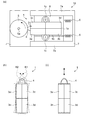
図1に示すように、第1の実施形態に係る駆動装置100は、圧電モーター10と、圧電モーター10を駆動する駆動信号供給部30と、圧電モーター10の動作により移動する可動部60と、第1の検知部としての力センサー50と、第2の検知部としてのエンコーダー11と、スイッチ12(図5参照)と、を備えている。
As shown in FIG. 1, the
また、第1の実施形態に係る駆動装置100は、その動作状態として、圧電モーター10を駆動して可動部60を移動させる第2の状態としての通常駆動モードと、圧電モーター10を駆動せず可動部60を手動で移動させる第1の状態としての教示モードと、を有している。なお、圧電モーター10を駆動している状態とは、後述する振動部1に屈曲振動を発生させて被駆動部5を駆動している状態をいう。
In addition, the driving
教示モードは、通常駆動モードで圧電モーター10を駆動して可動部60を所定の位置に移動させる作業を行う際に、例えば、駆動装置100を操作する操作者により、予め可動部60を手動で移動させて所定の位置に位置合わせする作業(以下では、この作業を教示作業という)等に用いられる。教示作業により位置合わせされた位置は、例えば、座標等の位置情報として駆動信号供給部30に記憶される。
In the teaching mode, when the
<圧電モーター>
まず、第1の実施形態に係る圧電モーター10の構成を説明する。図2は、第1の実施形態に係る圧電モーターの構成及び動作を示す模式図である。詳しくは、図2(a)は圧電モーターの平面図であり、図2(b)は通常駆動モードにおける圧電モーターの振動部の振動挙動を説明する図であり、図2(c)は教示モードにおける圧電モーターの振動部の振動挙動を説明する図である。図3は、圧電モーターの駆動電圧と回転数及び保持力との関係を模式的に示す図である。
<Piezoelectric motor>
First, the configuration of the
図2(a)に示すように、第1の実施形態に係る圧電モーター10は、振動部1と、被駆動部5と、保持部材8と、付勢バネ6と、基台7と、を備えている。振動部1、被駆動部5、保持部材8、及び付勢バネ6は、基台7に設置されている。なお、ここでは、被駆動部5が回転駆動されるローターである場合を例にとり説明する。
As shown in FIG. 2A, the
図2(a)に示す平面視で、振動部1は、短辺1aと長辺1bとを有する略矩形形状である。以下の説明では、短辺1aに沿った方向を短手方向と呼び、長辺1bに沿った方向を長手方向と呼ぶ。振動部1は、例えば、板状に形成された圧電素子で構成されるが、圧電素子と振動板とが積層された積層体であってもよい。
In the plan view shown in FIG. 2A, the vibration part 1 has a substantially rectangular shape having a
圧電素子は、電気機械変換作用を示す圧電材料からなり、例えば、一般式ABO3で示されるペロブスカイト構造を有する金属酸化物を材料として形成されている。このような金属酸化物としては、チタン酸ジルコン酸鉛(Pb(Zr,Ti)O3:PZT)、ニオブ酸リチウム(LiNbO3)等があげられる。 The piezoelectric element is made of a piezoelectric material exhibiting an electromechanical conversion action, and is formed using, for example, a metal oxide having a perovskite structure represented by a general formula ABO 3 . Examples of such metal oxides include lead zirconate titanate (Pb (Zr, Ti) O 3 : PZT), lithium niobate (LiNbO 3 ), and the like.
振動部1の表面には、Ni,Au,Ag等の導電性金属からなる電極3が設けられている。電極3は、振動部1の短手方向の中央部、及び長手方向の中央部に形成された溝部によって、略4等分されている。これにより、電極3は、個別電極として互いに電気的に隔離された電極部3a,3b,3c,3dの4つの電極部に分割されている。また、振動部1の反対側の表面には、共通電極9(図5参照)が設けられている。
An
電極3の4つの電極部のうち、互いに対角となるように配置され対を成す電極部3a,3dは、第1屈曲振動用電極として機能する。また、電極部3a,3dと交差する対角となるように配置され対を成す電極部3b,3cは、第2屈曲振動用電極として機能する。電極部3a,3dが配置された領域、及び電極部3b,3cが配置された領域が、それぞれ振動部1の長手方向に対して屈曲する屈曲振動を励起する屈曲振動励起領域となる。
Of the four electrode portions of the
駆動信号供給部30(図1参照)から、共通電極9に対して共通信号が供給され、第1屈曲振動用電極である電極部3a,3dに対して駆動信号が供給されると、振動部1に第1屈曲振動が励振される。一方、駆動信号供給部30から、共通電極9に対して共通信号が供給され、第2屈曲振動用電極である電極部3b,3cに対して駆動信号が供給されると、振動部1に、第1屈曲振動とは異なる向きの第2屈曲振動が励振される。
When a common signal is supplied from the drive signal supply unit 30 (see FIG. 1) to the
振動部1は、被駆動部5側に突出するように延設され、被駆動部5の側面(円周面)に当接する先端部4を有している。また、振動部1は、短手方向両外側に向かって延設された一対の腕部1cを有している。腕部1cには厚さ方向に貫通する貫通孔が設けられており、貫通孔を挿通させたネジを介して、腕部1cが保持部材8に固定されている。これにより、振動部1は、保持部材8に対して、腕部1cを基点として屈曲振動が可能な状態で保持される。
The vibration part 1 has a
被駆動部5は、円盤形状を有しており、振動部1の先端部4が設けられた側に配置されている。被駆動部5は、基台7に立設された棒状の軸5aを回転中心として、回転自在に保持されている。
The driven
基台7は、振動部1の短手方向の両外側に、長手方向に沿って延在して配置された一対のスライド部7aを有している。保持部材8は、基台7に対して、スライド部7aに沿ってスライド移動可能に支持されている。
The base 7 has a pair of
保持部材8の被駆動部5とは反対側と基台7との間には、付勢バネ6が設置されている。付勢バネ6は、保持部材8を介して振動部1を被駆動部5に向けて付勢し、この付勢力により、先端部4が被駆動部5に所定の力で当接する。付勢バネ6の付勢力は、被駆動部5と先端部4との間で適切な摩擦力が発生するように適宜設定されている。これにより、振動部1の振動が、先端部4を介して被駆動部5に効率良く伝達される。
A biasing
次に、圧電モーター10の動作を説明する。まず、第2の状態としての通常駆動モードにおける動作を説明する。通常駆動モードでは、図2(b)に示すように、振動部1に第1屈曲振動又は第2屈曲振動のいずれか一方を励振させることにより屈曲振動を発生させて被駆動部5を駆動する。図2(b)において、第1屈曲振動が励振された場合の振動部1の振動状態を破線で示し、第2屈曲振動が励振された場合の振動部1の振動状態を2点鎖線で示す。
Next, the operation of the
図2(b)に破線で示すように、振動部1に第1屈曲振動が励振されると、先端部4は、時計回りの楕円軌道R1を描くように動く。これにより、被駆動部5は、図2(a)に示す矢印の反時計回りに回転駆動される。また、図2(b)に2点鎖線で示すように、振動部1に第2屈曲振動が励振されると、先端部4は、反時計回りの楕円軌道R2を描くように動く。これにより、被駆動部5は、図2(a)に示す矢印とは反対の、時計回りに回転駆動される。
As shown by a broken line in FIG. 2B, when the first bending vibration is excited in the vibration part 1, the
通常駆動モードでは、駆動信号供給部30から共通電極9と電極部3a,3b,3c,3dとの間に駆動信号を供給する際に、第1屈曲振動用電極(電極部3a,3d)、又は第2屈曲振動用電極(電極部3b,3c)のいずれかが選択される。第1屈曲振動用電極を選択する場合と第2屈曲振動用電極を選択する場合とを切り替えることにより、被駆動部5を反時計回り及び時計回りの双方向に回転させることが可能である。
In the normal drive mode, when a drive signal is supplied from the drive
ところで、駆動信号供給部30から供給される駆動信号の電圧(以下では、駆動電圧という)がゼロ(0)の状態、すなわち、振動部1に駆動信号が供給されない非駆動状態では、先端部4が被駆動部5に当接しているので、先端部4と被駆動部5との間に摩擦力が働いている。したがって、この摩擦力を越える力が被駆動部5に加えられなければ、被駆動部5は、位置を移動する(回転する)ことなく保持される。圧電モーター10は、このような保持力を有することにより、電磁モーターやパルスモーターのように、被駆動部5の位置を保持するためのブレーキ機構を必要としない。
By the way, in the state where the voltage (hereinafter referred to as drive voltage) of the drive signal supplied from the drive
図3において、駆動電圧の上昇に伴う被駆動部5の回転数の変化を実線で示す。非駆動状態から振動部1に屈曲振動を発生させ駆動電圧を上昇させていくと、屈曲振動が大きくなるに伴って先端部4の楕円軌道が大きくなり、先端部4により被駆動部5を駆動しようとする駆動力が大きくなる。しかしながら、図3に実線で示すように、駆動電圧が第2の電圧値としての電圧値V3よりも低い間は、被駆動部5は回転を開始しない。
In FIG. 3, the change in the number of rotations of the driven
電圧値V3は、先端部4による駆動力が摩擦力を上回って被駆動部5が回転を開始する電圧値であり、振動部1の振動特性や先端部4と被駆動部5との間の摩擦力等によって定まるものである。駆動電圧が電圧値V3に達すると被駆動部5が回転を開始し、駆動電圧の上昇に伴って被駆動部5の回転数も上昇する。この駆動電圧と回転数との関係は、第1屈曲振動による駆動状態、及び第2屈曲振動による駆動状態において同じである。
The voltage value V3 is a voltage value at which the driven
駆動装置100は、このように通常駆動モードで振動部1に屈曲振動を発生させ、電圧値V3以上の駆動電圧で被駆動部5を回転駆動することにより、可動部60を移動させることができる。なお、駆動装置100における駆動電圧と回転数との関係は、振動部1の振動特性や、先端部4と被駆動部5との間の摩擦力等によって異なり、図3のようにリニアな関係とはならない場合がある。
The
続いて、第1の状態としての教示モードにおける圧電モーター10の動作を説明する。教示モードでは、図2(c)に示すように、振動部1に縦振動を発生させる。図2(c)において、振動部1が縦振動を発生している状態を破線と2点鎖線とで示す。縦振動は、駆動信号供給部30から、共通電極9に対して共通信号が供給され、第1屈曲振動用電極(電極部3a,3d)及び第2屈曲振動用電極(電極部3b,3c)の双方に駆動信号が供給された場合に発生する。
Next, the operation of the
第1屈曲振動用電極及び第2屈曲振動用電極の双方に駆動信号が供給されると、振動部1に、互いに向きが異なる第1屈曲振動と第2屈曲振動との2つの屈曲振動が励振される。そうすると、励振された第1屈曲振動と第2屈曲振動とが合成されて、振動部1に、長手方向に沿って伸縮する縦振動が発生する。振動部1に縦振動が発生すると、先端部4は、図2(c)に矢印で示すように、長手方向に沿って往復動する。なお、長軸が長手方向に沿った楕円軌道を描くように、先端部4が動く場合もある。
When a drive signal is supplied to both the first bending vibration electrode and the second bending vibration electrode, two bending vibrations of the first bending vibration and the second bending vibration having different directions are excited in the vibration unit 1. Is done. Then, the excited first bending vibration and second bending vibration are combined, and longitudinal vibration that expands and contracts along the longitudinal direction is generated in the vibration unit 1. When longitudinal vibration occurs in the vibration part 1, the
このように先端部4が長手方向に沿って往復動すると、先端部4と被駆動部5との接触は断続的になる。すなわち、先端部4が被駆動部5に接触した状態と、先端部4が被駆動部5から離れた状態とが繰り返され、先端部4が被駆動部5に接触したままの状態ではなくなる。これにより、非駆動状態に比べて保持力が低下する。この際、先端部4の往復動の方向が被駆動部5の回転中心に向かう方向であれば、駆動電圧を上昇させても被駆動部5は回転しない。
When the
図3において、振動部1に縦振動を発生させ駆動電圧を上昇させたときの保持力の変化を破線で示す。保持力は、被駆動部5を外力で移動(回転)させようとした場合に、外力に抗して被駆動部5を保持しようとする力である。非駆動状態における保持力、すなわち保持力の最大値(Max)は、先端部4と被駆動部5との間の摩擦力によって決まる。
In FIG. 3, a change in holding force when a longitudinal vibration is generated in the vibration unit 1 to increase the drive voltage is indicated by a broken line. The holding force is a force for holding the driven
非駆動状態から振動部1に縦振動を発生させ駆動電圧を上昇させていくと、保持力は、駆動電圧が電圧値V0よりも低い間は変化しないが、振動部1の縦振動が大きくなって先端部4が往復動を開始する電圧値V0に駆動電圧が達すると低下し始める。そして、駆動電圧の上昇に伴って先端部4の往復動のストロークが大きくなるので、保持力は、最小値(Min)に到達するまで低下を続ける。
When longitudinal vibration is generated in the vibration unit 1 from the non-driving state and the drive voltage is increased, the holding force does not change while the drive voltage is lower than the voltage value V0, but the longitudinal vibration of the vibration unit 1 increases. When the driving voltage reaches the voltage value V0 at which the
なお、電圧値V0は、振動部1の振動特性や先端部4と被駆動部5との間の摩擦力等によって定まるものであり、電圧値V3よりも小さい。また、駆動電圧と保持力との関係は、振動部1の振動特性や、先端部4と被駆動部5との間の摩擦力等によって異なり、図3のようにリニアな関係とはならない場合がある。
The voltage value V0 is determined by the vibration characteristics of the vibration part 1, the frictional force between the
駆動装置100では、このように教示モードで振動部1が縦振動を発生するので、保持力が低下する。そして、駆動電圧を適宜設定して被駆動部5の保持力を制御することで、可動部60を容易に手動で移動させて位置合わせを行うことが可能となる。
In the
なお、駆動装置100において、被駆動部5は、上述の回転駆動されるローターに限定されるものではない。被駆動部5は直線駆動されるリニア被駆動部であってもよく、被駆動部5の駆動方向は任意に構成できる。被駆動部5がリニア被駆動部である場合、第1屈曲振動用電極(電極部3a,3d)と第2屈曲振動用電極(電極部3b,3c)とを切り替えることにより、被駆動部5の直動方向を正方向と逆方向とで切り替えることができる。
In the
また、駆動装置100が、回転駆動される被駆動部5の回転数を増加又は減少して伝達する増減速機構をさらに備えた構成とすることも可能である。増減速機構を備えていると、被駆動部5の回転数を増加又は減少して所望の回転数を容易に得ることができる。
Further, the driving
図1に戻って、可動部60は、圧電モーター10の被駆動部5(図2(a)参照)が駆動されることにより移動する。可動部60は、直接被駆動部5に固定されていてもよいし、ギア輪列、ローラー、ベルトとプーリー等の増減速機構や伝達機構を介して被駆動部5に接続されていてもよい。
Returning to FIG. 1, the
力センサー50は、可動部60に設けられている。力センサー50は、可動部60に加えられた外力を検知し、検知した結果に基づく信号を、後述する駆動信号供給部30の副制御部22にフィードバックする。力センサー50は、例えば、圧力センサーやひずみゲージ等で構成される。
The
エンコーダー11は、圧電モーター10の被駆動部5に近い位置に設けられている。エンコーダー11は、被駆動部5の位置を検知し、検知した結果に基づくエンコーダー信号を副制御部22にフィードバックする。エンコーダー11による被駆動部5の位置の検知に基づいて、被駆動部5が外力により移動(回転)したことや、その移動量、回転速度等の回転状態を検出することができる。エンコーダー11は、例えば、フォトリフレクター、フォトインタラプター、MRセンサー等の、光方式や磁気方式の回転エンコーダー等で構成される。
The
<駆動信号供給部>
続いて、図4及び図5を参照して、駆動信号供給部30の構成を説明する。図4は、第1の実施形態に係る駆動信号供給部の概略構成を示すブロック図である。図5は、第1の実施形態に係る駆動信号供給部の要部を示すブロック図である。
<Drive signal supply unit>
Next, the configuration of the drive
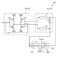
図4に示すように、駆動信号供給部30は、主制御部21と、副制御部22と、発振器31と、ゲインアンプ32と、PWM部33と、デジタルアンプ34と、整合回路40と、を備えている。
As shown in FIG. 4, the drive
主制御部21は、CPU(Central Processing Unit)で構成される。主制御部21は、駆動装置100を含むシステム全体を制御する制御装置(図示省略)と、CAN(Controller Area Network)を介して接続されている。主制御部21は、例えば、駆動電圧の指令値を副制御部22に指示する等の、駆動装置100全体の制御を行う。
The
副制御部22は、ロジックICやFPGA(Field Programmable Gate Array)等で構成される。副制御部22は、主制御部21とSPI(Serial Peripheral Interface)を介して接続されている。副制御部22は、主制御部21の指示に基づいて、発振器31で生成する信号の周波数、ゲインアンプ32の出力(増幅率)、スイッチ12(図5参照)の切り替え等の制御を行う。
The sub-control unit 22 is configured by a logic IC, an FPGA (Field Programmable Gate Array), or the like. The sub-control unit 22 is connected to the
副制御部22は、力センサー50からフィードバックされた信号に基づいて、可動部60に外力が加えられたことを検出する。また、副制御部22は、エンコーダー11からフィードバックされたエンコーダー信号に基づいて、圧電モーター10の被駆動部5に外力が加えられたことを検出する。そして、副制御部22は、エンコーダー11からフィードバックされたエンコーダー信号に基づいて、被駆動部5が外力により移動(回転)したことや、その移動量、回転速度等の回転状態を検出する。
The sub control unit 22 detects that an external force is applied to the
発振器31は、DDS(Direct Digital Synthesizer)等で構成される。発振器31は、圧電モーター10の振動部1に供給する駆動信号のもととなる信号を生成する。発振器31で生成された信号は、DAコンバーターによりアナログ信号に変換される。また、発振器31は、副制御部22の指示に基づいて、駆動信号の周波数を調整する。
The
ゲインアンプ32は、例えば、デジタルポテンショメーターとオペアンプとで構成される。ゲインアンプ32は、発振器31からのアナログ信号をデジタル制御により増幅する。ゲインアンプ32の出力レベルは、副制御部22の指示に基づいて制御(増加又は減少)される。ゲインアンプ32の出力レベルを増加又は減少させることにより、駆動信号の電圧(駆動電圧)が変化する。
The
PWM部33は、PWM(Pulse Width Modulation)回路で構成される。PWM部33は、ゲインアンプ32からの入力信号におけるパルスのデューティー比を変えることにより、等価的なアナログ制御を行なう。
The
図5に示すように、デジタルアンプ34は、MOSトランジスターのHブリッジ回路で構成され、PWM部33との併用により、デジタルアンプとして機能する。デジタルアンプ34は、PWM部33からの信号の電力を増幅してスイッチングを行う。なお、主制御部21からの「Sleep」指示(図4参照)があると、デジタルアンプ34における電力を増幅してスイッチングを行う機能はOFF状態となる。
As shown in FIG. 5, the
整合回路40は、デジタルアンプ34と圧電モーター10との間に接続されている。整合回路40は、デジタルアンプ34のインピーダンスと圧電モーター10のインピーダンスとの整合(マッチング)をとるとともに、圧電モーター10への出力電圧を昇圧する役割を担う。整合回路40は、コイル等のインダクター41,42と、コンデンサー等のキャパシター43とで構成されるLC整合回路である。
The matching
デジタルアンプ34は、整合回路40を介して、圧電モーター10の第1屈曲振動用電極(電極部3a,3d)、第2屈曲振動用電極(電極部3b,3c)に駆動信号を出力し、共通電極9に共通信号を出力する。圧電モーター10の第1屈曲振動用電極及び第2屈曲振動用電極の前段にはスイッチ12が接続されている。
The
スイッチ12は、副制御部22(図4参照)の指示に基づいて動作し、第1屈曲振動用電極及び第2屈曲振動用電極とデジタルアンプ34とが整合回路40を介して電気的に接続した状態又は電気的に切断した状態に切り替える。スイッチ12は、電磁リレー等のメカニカルリレーやフォトモスリレー等の電子式リレーで構成される。なお、スイッチ12に手動のトグルスイッチを用いる構成としてもよい。
The
図5では、教示モードにおけるスイッチ12の状態を示している。教示モードでは、スイッチ12により、第1屈曲振動用電極及び第2屈曲振動用電極の双方をデジタルアンプ34と接続することで、振動部1が縦振動を発生する状態となる。また、通常駆動モードでは、スイッチ12により、第1屈曲振動用電極又は第2屈曲振動用電極のいずれかを選択してデジタルアンプ34と接続することで、振動部1が屈曲振動を発生する状態となる。そして、スイッチ12を切り替えることにより、被駆動部5の回転方向を反時計回りと時計回りとで切り替えることができる。
FIG. 5 shows the state of the
<圧電モーターの駆動方法>
続いて、図6を参照して、第1の実施形態に係る駆動装置100において教示作業を行う場合の圧電モーターの駆動方法を説明する。図6は、教示作業における圧電モーターの駆動方法を示すフローチャートである。上述の通り、教示作業を行う際は、圧電モーター10の振動部1に縦振動を発生させて教示モードとする。
<Piezoelectric motor drive method>
Next, with reference to FIG. 6, a method for driving the piezoelectric motor when performing the teaching work in the
教示作業をスタートする際は、副制御部22は、駆動信号供給部30からの駆動電圧をゼロ(0)に設定し、圧電モーター10を非駆動状態とする。この状態では、保持力が最大値となっているため、例えば教示作業を行う操作者が可動部60を手動で移動させようとしても、被駆動部5の位置を保持する保持力が大きいため移動させることは困難である。しかしながら、可動部60を手動で移動させようとして可動部60に加えられた力は、力センサー50により検知される。
When starting the teaching work, the sub-control unit 22 sets the drive voltage from the drive
図6に示すように、駆動装置100では、可動部60に外力が加えられたことが検出されるまでは非駆動状態で待機する。力センサー50が可動部60に加えられた外力を検知すると、副制御部22は、力センサー50からフィードバックされた信号に基づいて可動部60に外力が加えられたことを検出する(ステップS1)。
As shown in FIG. 6, the driving
可動部60に外力が加えられたことが検出された場合(ステップS1:YES)、副制御部22は、スイッチ12を切り替えて、第1屈曲振動用電極及び第2屈曲振動用電極の双方をデジタルアンプ34と接続する。そして、副制御部22は、振動部1に供給される駆動電圧を、保持力が低下し始める電圧値V0以上の電圧値V1に設定する(ステップS2)。これにより、駆動装置100は、振動部1が縦振動を発生する教示モードに移行する。
When it is detected that an external force is applied to the movable part 60 (step S1: YES), the sub-control part 22 switches the
ステップS2で、振動部1が縦振動を発生し、駆動電圧を電圧値V1に設定することにより被駆動部5の保持力が低下するので、被駆動部5を外力で容易に移動(回転)させることが可能となる。すなわち、可動部60を手動で動かして位置合わせを行うことが可能となる。ステップS2の設定を行った後、処理をステップS3に進める。
In step S2, the vibration unit 1 generates longitudinal vibration, and the holding voltage of the driven
ここで、本実施形態では、図3に示すように、教示モードにおける駆動電圧の電圧値V1を、保持力が低下し始める電圧値V0以上で、かつ、通常駆動モードで被駆動部5が回転を開始する電圧値V3よりも低い電圧値としている。電圧値V1を電圧値V3よりも低い電圧値とするのは、以下の理由による。
In this embodiment, as shown in FIG. 3, the voltage value V1 of the driving voltage in the teaching mode is equal to or higher than the voltage value V0 at which the holding force starts to decrease, and the driven
振動部1が縦振動する際、先端部4の往復動の方向が被駆動部5の回転中心に向かう方向であれば被駆動部5は回転しないが、先端部4の往復動の方向が被駆動部5の回転中心に向かう方向からずれている場合、被駆動部5が回転してしまうことがあり得る。このような場合でも、駆動電圧を電圧値V3よりも低い電圧値V1とすることで、被駆動部5が先端部4の往復動によって回転してしまうことを抑止できる。
When the vibration part 1 vibrates longitudinally, the driven
次に、図6に示すステップS3では、駆動電圧の電圧値の設定が変更された後所定の時間以内に被駆動部5が外力により移動(回転)したか否かを検出する。ステップS2の設定を行った後に可動部60を手動で移動させると、加えられた力が可動部60を介して伝達されて被駆動部5が移動(回転)するので、エンコーダー11により被駆動部5の移動(回転)が検知される。そして、エンコーダー11からフィードバックされたエンコーダー信号に基づいて、副制御部22は、被駆動部5に外力が加えられた(可動部60に加えられた力が被駆動部5に伝達された)ことを検出する。
Next, in step S3 shown in FIG. 6, it is detected whether or not the driven
駆動電圧の電圧値の設定が変更された後所定の時間以内に、被駆動部5に外力が伝達されたことが検出された場合(ステップS3:YES)、副制御部22は、振動部1に縦振動をさせた状態で、駆動電圧を電圧値V2に設定し教示モードに移行したときの電圧値よりも高くする(ステップS4)。教示作業は、このステップS4の状態で行われる。そして、ステップS4の設定を行った後所定の時間が経過したら、処理をステップS3に戻す。
When it is detected that an external force has been transmitted to the driven
図3に示すように、ステップS4で設定される電圧値V2は、ステップS2で設定された電圧値V1よりも高く、かつ、電圧値V3よりも低い電圧値とする。これにより、駆動電圧が電圧値V1の場合と比べて、被駆動部5の保持力がより低下するので、弱い力でも容易に可動部60を移動させることができ、より精度良く所定の位置に位置合わせを行うことができる。なお、電圧値V1,V2は、圧電モーター10の保持力の大きさや電圧値V3の値等に応じて適宜設定される。
As shown in FIG. 3, the voltage value V2 set in step S4 is higher than the voltage value V1 set in step S2 and lower than the voltage value V3. As a result, the holding force of the driven
一方、駆動電圧の電圧値の設定が変更された後所定の時間以内に、被駆動部5に外力が伝達されたことが検出されなかった場合(ステップS3:NO)、処理をステップS5に移行して教示モードでの動作を終了する。ステップS5では、駆動電圧をゼロ(0)に設定し非駆動状態とする。これにより、保持力が最大値となるので、被駆動部5が位置合わせを行った位置で保持される。ステップS5の後、処理をステップS6に進める。
On the other hand, when it is not detected that an external force is transmitted to the driven
ステップS6では、教示作業が終了したか否かを判定する。教示作業が終了した場合は、操作者の指示に基づいて、主制御部21に教示作業が終了した旨の信号が入力される。教示作業が終了していない場合(ステップS6:NO)、処理をステップS1に戻す。教示作業が終了した場合(ステップS6:YES)は、全処理を終了する。
In step S6, it is determined whether or not the teaching work has been completed. When the teaching work is completed, a signal indicating that the teaching work is completed is input to the
以上、教示作業における圧電モーターの駆動方法について説明したが、駆動装置が力センサー50又はエンコーダー11のいずれか一方のみを備えた構成とすることも可能である。すなわち、力センサー50により外力が検出されたらステップS2を行うか、エンコーダー11により外力が検出されたらステップS4を行うか、のいずれか一方の処理だけを行うことも可能である。
As described above, the driving method of the piezoelectric motor in the teaching work has been described. However, the driving device may have only one of the
しかしながら、力センサー50により外力が検出されたらステップS2を行って1段階だけ保持力を低下させる場合、ステップS2における駆動電圧(電圧値V1)が低いと保持力が高めとなり位置合わせが行いにくくなる可能性がある。
However, when an external force is detected by the
また、エンコーダー11により外力が検出されたらステップS4を行って1段階だけ保持力を低下させる場合、予め被駆動部5が外力で移動可能な状態にしておかなければならないため、教示作業のスタート時から駆動電圧を電圧値V0よりも高く設定し、保持力を低下させた状態で待機する必要がある。そのため、不用意な接触や誤操作等により可動部60を誤って移動させてしまうことや、待機中の消費電力の増大を招く可能性がある。
Further, when the external force is detected by the
これに対して、本実施形態の駆動装置の構成及び駆動方法では、力センサー50及びエンコーダー11の双方によって外力を検出し、ステップS2とステップS4との2段階で保持力を低下させることとしている。すなわち、教示作業スタート時は外力で可動部60を動かすことが困難な非駆動状態で待機し、可動部60に何らかの外力が加えられた場合に、教示モードに移行して可動部60を動かすことが可能な状態とする。そして、続けて可動部60に外力が加えられた場合には、可動部60に加えられた外力が不用意な接触や誤操作等によるものでなく意図して加えられたものであると判断して、可動部60をより容易に動かすことができる状態とする。これにより、誤操作を抑えて確実に教示作業を行うことができる。また、教示モードに移行するまでの待機中の消費電力を抑えることができる。
On the other hand, in the configuration and the driving method of the driving device of the present embodiment, the external force is detected by both the
以上述べたように、第1の実施形態に係る駆動装置100の構成、及びその駆動方法によれば、以下の効果が得られる。
As described above, according to the configuration of the driving
(1)駆動装置100では、圧電モーター10の振動部1に駆動信号を供給しない非駆動状態から振動部1に縦振動を発生させる教示モードに移行することができる。教示モードでは、振動部1が縦振動することにより、振動部1と被駆動部5との接触が断続的となる。そのため、教示モードでは、駆動信号供給部30から振動部1に駆動信号が供給されない非駆動状態に比べて、被駆動部5の位置を保持する保持力が低下するので、可動部60に外力が加えられた場合に可動部60が移動し易くなる。したがって、可動部60を手動で動かして容易に位置合わせを行うことが可能な駆動装置100を提供できる。
(1) In the
(2)駆動装置100では、教示モードにおいて駆動信号供給部30が振動部1に供給する駆動信号の電圧値V1は、振動部1に屈曲振動を発生させる通常駆動モードにおいて被駆動部5が駆動され回転を開始する電圧値V3よりも低い。そのため、教示モードにおいて駆動電圧を上昇させると被駆動部5が駆動され回転してしまう場合でも、駆動信号の電圧値を電圧値V3よりも低い電圧値V1とすることで、被駆動部5が回転することを抑止できる。これにより、可動部60の位置合わせをより確実に行うことができる。
(2) In the
(3)駆動装置100では、非駆動状態において力センサー50が可動部60に加えられた外力を検知した場合に、教示モードに移行して保持力を低下させる。そのため、例えば教示作業を行う操作者が、可動部60を動かそうとする力を加えることで、可動部60を手動で動かして位置合わせできる状態に切り替えることができる。
(3) In the
(4)駆動装置100では、教示モードにおいてエンコーダー11が可動部60に加えられた外力を検知した場合に、駆動信号の電圧値を教示モードを選択したときの電圧値V1よりも高い電圧値V2に設定して保持力を低下させる。そのため、弱い力でも容易に可動部60を動かして位置合わせを行うことができる。
(4) In the
(5)駆動装置100では、非駆動状態において力センサー50が外力を検知した場合に教示モードに移行して保持力を低下させ、教示モードにおいてエンコーダー11が外力を検知した場合に、教示モードに移行したときよりも保持力をさらに低下させる。そのため、予め保持力を低下させておかなくてもよく、また、力センサー50とエンコーダー11とのそれぞれで外力を検知して2段階で保持力を低下させることができる。これにより、不用意な接触や誤操作による可動部60の移動を抑えて、確実かつ容易に可動部60の位置合わせを行うことができる。また、教示モードに移行するまでの待機中の消費電力を抑えることができる。
(5) In the
(第2の実施形態)
<駆動装置>
次に、第2の実施形態に係る駆動装置の概略構成を説明する。第2の実施形態に係る駆動装置は、第1の実施形態に対して、圧電モーターの振動部の電極が5つの電極部に分割されている点が異なっているが、その他の構成はほぼ同じである。第1の実施形態と共通する構成要素については、同一の符号を付しその説明を省略する。
(Second Embodiment)
<Drive device>
Next, a schematic configuration of the drive device according to the second embodiment will be described. The driving device according to the second embodiment is different from the first embodiment in that the electrode of the vibration part of the piezoelectric motor is divided into five electrode parts, but the other configurations are substantially the same. It is. Constituent elements common to the first embodiment are denoted by the same reference numerals and description thereof is omitted.
図7は、第2の実施形態に係る駆動信号供給部の要部を示すブロック図である。図8は、第2の実施形態に係る圧電モーターの構成及び動作を示す模式図である。詳しくは、図8(a)は圧電モーターの平面図であり、図8(b)は通常駆動モードにおける圧電モーターの振動部の振動挙動を説明する図であり、図8(c)は教示モードにおける圧電モーターの振動部の振動挙動を説明する図である。 FIG. 7 is a block diagram illustrating a main part of a drive signal supply unit according to the second embodiment. FIG. 8 is a schematic diagram illustrating the configuration and operation of the piezoelectric motor according to the second embodiment. Specifically, FIG. 8A is a plan view of the piezoelectric motor, FIG. 8B is a diagram for explaining the vibration behavior of the vibration part of the piezoelectric motor in the normal drive mode, and FIG. 8C is a teaching mode. It is a figure explaining the vibration behavior of the vibration part of the piezoelectric motor in FIG.
図7に示すように、第2の実施形態に係る駆動装置101は、圧電モーター10Aと、駆動信号供給部30と、スイッチ12Aと、図示を省略する可動部60と力センサー50とエンコーダー11と、を備えている。
As shown in FIG. 7, the
<圧電モーター>
図8(a)に示すように、第2の実施形態に係る圧電モーター10Aは、振動部2と、被駆動部5と、保持部材8と、付勢バネ6と、基台7と、を備えている。
<Piezoelectric motor>
As shown in FIG. 8A, the
振動部2の電極3の表面は5分割されており、電極部3a,3b,3c,3dに加えて、電極部3eが設けられている。電極部3eは、電極部3a,3bと電極部3c,3dとの間の短手方向中央部に配置されており、電極部3a,3bを合わせた面積(電極部3c,3dを合わせた面積)とほぼ同じ面積を有している。電極部3eは、縦振動用電極として機能する。縦振動用電極である電極部3eに対して駆動信号が供給されることにより、振動部2に縦振動が励振される。
The surface of the
図7では、教示モードにおけるスイッチ12Aの状態を示している。図7に示すように、第2の実施形態に係る駆動装置101では、教示モードにおいて駆動信号供給部30から縦振動用電極(電極部3e)のみに対して駆動信号が供給される。また、通常駆動モードにおいては、駆動信号供給部30から、縦振動用電極(電極部3e)に駆動信号が供給されるとともに、スイッチ12Aの切り替えにより選択された第1屈曲振動用電極(電極部3a,3d)又は第2屈曲振動用電極(電極部3b,3c)のいずれか一方に駆動信号が供給される。
FIG. 7 shows the state of the
次に、圧電モーター10Aの動作を説明する。通常駆動モードでは、縦振動用電極と、第1屈曲振動用電極又は第2屈曲振動用電極のいずれか一方と、に駆動信号が供給されることにより、振動部2に縦振動と第1屈曲振動又は第2屈曲振動のいずれか一方の屈曲振動とが励振される。そうすると、振動部2は、縦振動と屈曲振動とが合成された屈曲振動を発生する。
Next, the operation of the
図8(b)において、縦振動と第1屈曲振動とが励振された場合の振動部2の振動状態を破線で示し、縦振動と第2屈曲振動とが励振された場合の振動部2の振動状態を2点鎖線で示す。図8(b)に破線で示すように、振動部2に縦振動と第1屈曲振動とが励振されると、先端部4は、時計回りの楕円軌道R1を描くように動く。これにより、被駆動部5は、図8(a)に示す矢印の反時計回りに回転駆動される。
In FIG. 8B, the vibration state of the
また、図8(b)に2点鎖線で示すように、振動部2に縦振動と第2屈曲振動とが励振されると、先端部4は、反時計回りの楕円軌道R2を描くように動く。これにより、被駆動部5は、図8(a)に示す矢印とは反対の、時計回りに回転駆動される。したがって、第2の実施形態に係る圧電モーター10Aにおいても、第1屈曲振動用電極を選択する場合と第2屈曲振動用電極を選択する場合とを切り替えることにより、被駆動部5を反時計回り及び時計回りの双方向に回転させることが可能である。
Further, as shown by a two-dot chain line in FIG. 8B, when longitudinal vibration and second bending vibration are excited in the
一方、教示モードでは、縦振動用電極のみに駆動信号が供給されることにより、振動部2に縦振動のみが励振されるので、図8(c)に破線と2点鎖線とで示すように、振動部2に縦振動が発生する。これにより、第2の実施形態に係る圧電モーター10Aにおいても、先端部4は、図8(c)に矢印で示すように、長手方向に沿って往復動する。したがって、被駆動部5は回転せず、駆動電圧を保持力が低下し始める電圧値V0以上に設定することで、保持力を低下させることができる。
On the other hand, in the teaching mode, only the longitudinal vibration is excited in the
このように、第2の実施形態に係る駆動装置101は、振動部2の電極が5分割され屈曲振動用の電極部3a,3b,3c,3dに加えて縦振動用の電極部3eを有する圧電モーター10Aを備えているが、第1の実施形態と同様に動作する。すなわち、駆動装置101の構成によれば、通常駆動モードでは圧電モーター10Aで駆動して可動部60を移動させ、教示モードでは手動で可動部60を移動させることができる。したがって、第1の実施形態に係る圧電モーターの駆動方法が適用できるので、第1の実施形態に係る駆動装置100と同様の効果が得られる。
As described above, the
なお、教示モードにおいて、縦振動用電極と第1屈曲振動用電極及び第2屈曲振動用電極の双方とに駆動信号を供給することで、振動部2に縦振動を発生させる構成とすることも可能である。
In the teaching mode, the
(第3の実施形態)
<電子部品搬送装置及び電子部品検査装置>
次に、第3の実施形態に係る電子部品搬送装置及び電子部品検査装置を説明する。第3の実施形態に係る電子部品搬送装置及び電子部品検査装置は、第1の実施形態又は第2の実施形態に係る駆動装置を備えている。以下では、第1の実施形態に係る駆動装置における構成要素の符号を付して説明し、第2の実施形態に係る駆動装置における構成要素の符号は省略する。
(Third embodiment)
<Electronic component conveying device and electronic component inspection device>
Next, an electronic component transport device and an electronic component inspection device according to a third embodiment will be described. The electronic component transport device and the electronic component inspection device according to the third embodiment include the drive device according to the first embodiment or the second embodiment. Hereinafter, the reference numerals of the components in the drive device according to the first embodiment will be given and described, and the reference numerals of the components in the drive device according to the second embodiment will be omitted.
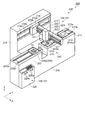
図9は、第3の実施形態に係る電子部品搬送装置及び電子部品検査装置の構成を示す概略斜視図である。図9に示す電子部品検査装置200は、電子部品搬送装置230と、検査部としての検査装置240とを備えている。電子部品搬送装置230は、電子部品70を所定の場所に搬送するとともに、電子部品70を所定の位置に位置決めする機能を有する。検査装置240は、電子部品70の電気的特性を検査する機能を有する。
FIG. 9 is a schematic perspective view illustrating configurations of an electronic component transport device and an electronic component inspection device according to the third embodiment. The electronic
なお、電子部品70は、例えば、基板に半導体チップが実装されたものであるが、半導体チップ、LCD等の表示デバイス、水晶デバイス、各種センサー、インクジェットヘッド等であってもよい。
The
図9に示すように、電子部品搬送装置230は、直方体状の基台206を備えている。基台206の長手方向をY方向とし、水平面においてY方向と直交する方向をX方向とする。そして、鉛直方向を−Z方向とする。
As shown in FIG. 9, the electronic
基台206上において図中左側には、給材装置207が設置されている。給材装置207の上面には、Y方向に延びる一対の案内レール208a,208bが給材装置207のY方向全幅にわたり凸設されている。一対の案内レール208a,208bの上側には、直動機構を備えたステージ209が取付けられている。
On the
ステージ209の直動機構は、例えば、案内レール208a,208bに沿ってY方向に延びるリニアモーターを備えた直動機構である。この直動機構に所定のステップ数に相当する駆動信号がリニアモーターに入力されると、リニアモーターが前進又は後退して、ステージ209が同ステップ数に相当する分だけ、Y方向に沿って往動又は復動する。ステージ209のZ方向を向く面は載置面209aであり、載置面209aにはこれから検査される電子部品70が載置される。ステージ209には吸引式の基板チャック機構が設置されている。そして、基板チャック機構が電子部品70を載置面209aに固定するようになっている。
The linear motion mechanism of the
基台206において給材装置207のY方向側には、撮像部210が設置されている。撮像部210は、受光する光を電気信号に変換するCCD(Charge Coupled Devices)素子等を搭載した電気回路基板、ズーム機構を備えた対物レンズ、落射照明装置、自動焦点合わせ機構を備えている。これにより、撮像部210と対向する場所に電子部品70が位置するとき、撮像部210は電子部品70を撮影して位置決めをすることができる。撮像部210は、電子部品70に光を照射してピント合わせをした後撮影することにより、ピンボケの無い画像を撮影することができる。
An
基台206において撮像部210のY方向側には、検査装置240が備える検査台211が設置されている。検査台211は、電子部品70を検査するときに電気信号を送受信するための治具である。なお、検査装置240は、検査台211と、把持部225と、制御部(制御装置226に含む)とで構成される。検査台211及び把持部225には、電子部品70の電気的特性を計測するための複数のプローブが配置されている。
On the
基台206上において検査台211のY方向側には、除材装置212が設置されている。除材装置212の上面には、Y方向に延びる一対の案内レール213a,213bが全幅にわたり凸設されている。一対の案内レール213a,213bの上側には、直動機構を備えたステージ214が取付けられている。ステージ214の直動機構は、給材装置207が備える直動機構と同様の機構を用いることができる。ステージ214は、案内レール213a,213bに沿って往動又は復動する。ステージ214のZ方向を向く面は載置面214aであり、載置面214aには検査が終了した電子部品70が載置される。
A
基台206の−X方向には、略直方体状の支持台215が設置されている。支持台215は、基台206に比べてZ方向に高い形状となっている。支持台215においてX方向を向く面には、Y方向に延びる一対のレール216a,216bが、支持台215のY方向全幅にわたり凸設されている。レール216a,216bのX方向側には、一対のレール216a,216bに沿って移動する直動機構を備えたYステージ217が取付けられている。
A
Yステージ217の直動機構は、第1の実施形態に係る駆動装置100、又は第2の実施形態に係る駆動装置101を用いて構成されている。レール216a,216bの少なくとも一方が、圧電モーター10の被駆動部5に相当する。ここでは、被駆動部5(レール216a,216b)は、直線駆動されるリニア被駆動部である。振動部1(図示省略)は、レール216a,216bの少なくとも一方に当接して、Yステージ217に備えられている。通常駆動状態で振動部1が振動することにより、固定されたレール216a,216bに対して、相対的にYステージ217がレール216a,216bに沿って往動又は復動する。
The linear motion mechanism of the
Yステージ217においてX方向を向く面には、X方向に延在する角柱状の腕部218が設置されている。腕部218において−Y方向を向く面には、X方向に延びる一対のレール219a,219bが腕部218のX方向全幅にわたり凸設されている。一対のレール219a,219bの−Y方向側には、レール219a,219bに沿って移動する直動機構を備えたXステージ220が取付けられている。
On the surface of the
Xステージ220の直動機構は、Yステージ217の直動機構と同様に、第1の実施形態に係る駆動装置100、又は第2の実施形態に係る駆動装置101を用いて構成されている。通常駆動状態でXステージ220に備えられた振動部1が振動することにより、被駆動部5であるレール219a,219bに対して、相対的にXステージ220がレール219a,219bに沿って往動又は復動する。
Similar to the linear motion mechanism of the
Xステージ220には、撮像部221及びZ移動装置222が設置されている。撮像部221は、撮像部210と同様な構造と機能を備えている。
An
Z移動装置222は、内部に直動機構を備え、直動機構はZステージを昇降させる。Zステージには、回転装置223が接続されている。Z移動装置222は、回転装置223をZ方向に昇降させることができる。Z移動装置222の直動機構も、Yステージ217及びXステージ220の直動機構と同様に、第1の実施形態に係る駆動装置100、又は第2の実施形態に係る駆動装置101を用いて構成されている。
The
回転装置223は回転軸223aを備え、回転軸223aには把持部225が接続されている。把持部225には、検査対象となる電子部品70が把持される。回転装置223は、Z方向を軸にして、電子部品70を把持した状態で把持部225を回転させることができる。
The
回転装置223は、第1の実施形態に係る駆動装置100、又は第2の実施形態に係る駆動装置101を用いて構成され、回転軸223aを所定の角度に回動させる。ここでは、回転駆動される回転軸223aが、圧電モーター10の被駆動部5に相当する。
The
Yステージ217、Xステージ220、Z移動装置222、回転装置223等により可動部224が構成されている。なお、Yステージ217、Xステージ220、Z移動装置222、回転装置223のそれぞれには、第1の実施形態に係る駆動装置100、又は第2の実施形態に係る駆動装置101の力センサー50及びエンコーダー11が設けられている。
A
基台206のX方向側には、制御装置226が設置されている。制御装置226は、電子部品70を検査する検査装置240を含む電子部品検査装置200の動作を制御する機能を備えている。また、制御装置226には、第1の実施形態に係る駆動装置100、又は第2の実施形態に係る駆動装置101の駆動信号供給部30が含まれている。制御装置226は、入力装置226a及び出力装置226bを備えている。
A
入力装置226aは、キーボードや入力コネクター等であり、信号やデータの他に操作者の指示を入力する装置である。出力装置226bは、表示装置や外部装置に出力する出力コネクター等であり、信号やデータを他装置へ出力する。出力装置226bは、電子部品検査装置200の状況を操作者に伝達する装置でもある。
The
電子部品検査装置200では、検査対象となる電子部品70を把持部225に把持して、電子部品搬送装置230の可動部224によりステージ209から検査台211へ搬送して位置決めした後、検査装置240により電気特性の検査を行う。電気特性の検査が終了すると、電子部品搬送装置230の可動部224により電子部品70をステージ214まで搬送する。
In the electronic
第3の実施形態に係る電子部品検査装置200(電子部品搬送装置230)は、可動部224を構成するYステージ217、Xステージ220、Z移動装置222、回転装置223に、第1の実施形態に係る駆動装置100、又は第2の実施形態に係る駆動装置101を備えている。
In the electronic component inspection apparatus 200 (electronic component transport apparatus 230) according to the third embodiment, the
したがって、駆動装置100,101を通常駆動モードで駆動してこれらの可動部224を所定の位置に移動させる作業を行う際に、予め可動部224を手動で移動させて所定の位置に位置合わせし、その位置情報(座標等)を制御装置226に記憶させておく教示作業を、教示モードで誤操作を抑えて容易かつ確実に行うことができる。
Therefore, when the
なお、電子部品検査装置200において、上述の電子部品搬送装置230の構成部分の一部を検査装置240側に備える構成としてもよい。
The electronic
(第4の実施形態)
<ロボット>
次に、第4の実施形態に係るロボットを説明する。第4の実施形態に係るロボットは、ロボットハンドを有し、ロボット及びロボットハンドの指部及び腕部の駆動装置として、第1の実施形態に係る駆動装置100、又は第2の実施形態に係る駆動装置101を備えている。以下では、第1の実施形態に係る駆動装置における構成要素の符号を付して説明し、第2の実施形態に係る駆動装置における構成要素の符号は省略する。
(Fourth embodiment)
<Robot>
Next, a robot according to a fourth embodiment will be described. The robot according to the fourth embodiment has a robot hand, and the
図10は、第4の実施形態に係るロボットハンド及びロボットの構造を示す模式図である。詳しくは、図10(a)はロボットが備えるロボットハンドの構造を示す模式図であり、図10(b)はロボットの構造を示す模式図である。 FIG. 10 is a schematic diagram illustrating the structure of a robot hand and a robot according to the fourth embodiment. Specifically, FIG. 10A is a schematic diagram illustrating a structure of a robot hand included in the robot, and FIG. 10B is a schematic diagram illustrating a structure of the robot.
図10(a)に示すように、ロボットハンド300は、ハンド本体部301と、可動部としての2つの指部302と、制御装置307と、を備えている。2つの指部302は、ハンド本体部301に設置されている。
As shown in FIG. 10A, the
2つの指部302は、3つの関節部304と3つの指部材303とが交互に接続されて構成されている。3つの関節部304には、それぞれ第1の実施形態に係る駆動装置100、又は第2の実施形態に係る駆動装置101の圧電モーター10が設けられている。
The two
制御装置307には、駆動信号供給部30が配置されている。関節部304に設けられた圧電モーター10を駆動することにより、関節部304を回動させて指部302を人間の指のように所望の形態に変形(移動)させることが可能になっている。
A drive
図10(b)に示すように、ロボット310は、ロボット本体部311と、可動部としての2つの腕部312と、制御装置317と、を備えている。2つの腕部312は、ロボット本体部311に設置されている。
As shown in FIG. 10B, the
2つの腕部312は、3つの関節部314と2つの腕部材313とが交互に接続されて構成されている。3つの関節部314には、それぞれ第1の実施形態に係る駆動装置100、又は第2の実施形態に係る駆動装置101の圧電モーター10が設けられている。腕部312の一端はロボット本体部311に設置され、他端にはロボットハンド300が設置されている。ロボットハンド300は、図10(a)と同様の構成を有する。
The two
制御装置317には、第1の実施形態に係る駆動装置100、又は第2の実施形態に係る駆動装置101の駆動信号供給部30が配置されている。関節部314に設けられた圧電モーター10を駆動することにより、関節部314を回動させて腕部312を人間の腕のように所望の形態に変形させることが可能になっている。
In the
第4の実施形態に係るロボットハンド300及びロボット310は、関節部304及び関節部314を回動させて指部302及び腕部312を変形(移動)させる装置として、第1の実施形態に係る駆動装置100、又は第2の実施形態に係る駆動装置101を備えている。
The
したがって、駆動装置100,101を通常駆動モードで駆動してこれらの関節部304及び関節部314を回動させ、指部302や腕部312を所定の形態に変形させる作業を行う際に、予め指部302や腕部312を手動で移動させて所定の形態に変形させ、その位置情報(座標等)を制御装置307,317に記憶させておく教示作業を、教示モードで誤操作を抑えて容易かつ確実に行うことができる。
Accordingly, when the driving
なお、上述した実施の形態は、あくまでも本発明の一態様を示すものであり、本発明の範囲内で任意に変形及び応用が可能である。変形例を以下に述べる。 The above-described embodiment is merely an aspect of the present invention, and can be arbitrarily modified and applied within the scope of the present invention. A modification will be described below.
(変形例1)
上述した第1の実施形態及び第2の実施形態では、駆動装置100,101が、力センサー50及びエンコーダー11の双方で外力を検知し、ステップS1及びステップS2とステップS3及びステップS4とで、段階的に保持力を低下させる構成であったが、これに限定されるものではない。
(Modification 1)
In the first embodiment and the second embodiment described above, the driving
例えば、力センサー50及びエンコーダー11の双方で外力を検知可能な状態として2段階で保持力を低下させる状態と、力センサー50のみにより外力を検知可能な状態として1段階で保持力を低下させる状態と、エンコーダー11のみにより外力を検知可能な状態として1段階で保持力を低下させる状態と、力センサー50及びエンコーダー11の双方が外力を検知しない状態と、を切り替える切り替え部を備えた構成としてもよい。このような構成にすれば、可動部の構成や、教示作業の目的、内容等に応じて上述の状態を選択、又は切り替えることにより、様々な状況に対応して教示作業を適切に行うことができ、教示作業を行わない場合には外力が加えられても教示モードに移行しないようにすることができる。
For example, the state in which the external force can be detected by both the
(変形例2)
また、上述した実施形態では、教示モードは駆動装置の教示作業を目的とするものであったが、これに限定されるものではない。例えば、教示モードを、操作者等の人が誤って装置に接触してしまった場合でも、その人に危害が与えられることを抑止する安全モードとして利用してもよい。
(Modification 2)
In the above-described embodiment, the teaching mode is intended for teaching operation of the driving device, but is not limited to this. For example, the teaching mode may be used as a safety mode for preventing a person from being harmed even if a person such as an operator accidentally touches the apparatus.
安全モードとする場合は、力センサー50及びエンコーダー11の代わりに、あるいは力センサー50及びエンコーダー11に加えて、赤外線、レーザー等のセンサーや体温を感知するセンサー等、人間の接近を検知できるセンサーを備えることが好ましい。これらのセンサーで人間の接近を検知した場合に圧電モーターの保持力を低下させるようにすれば、操作者等の人が誤って装置に接触してしまった場合でも可動部が移動してよけることが可能となるので、可動部との接触によりその人に危害が与えられることを抑止できる。
In the case of the safety mode, instead of the
(変形例3)
上述した実施形態では、駆動信号供給部30にデジタルアンプ34を用いていたが、これに限定されるものではなく、駆動信号供給部30にアナログアンプを用いた構成としてもよい。駆動信号供給部30にアナログアンプを用いる場合、PWM部33及び整合回路40は削除される。
(Modification 3)
In the above-described embodiment, the
1,2…振動部、5…被駆動部、10,10A…圧電モーター、11…第2の検知部としてのエンコーダー、30…駆動信号供給部、50…第1の検知部としての力センサー、60…可動部、70…電子部品、100,101…駆動装置、200…電子部品検査装置、224…可動部、230…電子部品搬送装置、240…検査部としての検査装置、300…ロボットハンド、302…可動部としての指部、312…可動部としての腕部、310…ロボット。
DESCRIPTION OF
Claims (11)
縦振動及び屈曲振動を発生する振動部と前記振動部の前記屈曲振動により駆動される被駆動部とを有し、前記振動部が前記被駆動部を駆動することにより前記可動部を移動させる圧電モーターと、
前記振動部に駆動信号を供給する駆動信号供給部と、を備え、
前記振動部に前記駆動信号を供給しない非駆動状態から、前記振動部に前記縦振動を発生させる第1の状態に移行することが可能であることを特徴とする駆動装置。 Moving parts;
A piezoelectric device having a vibration part that generates longitudinal vibration and bending vibration and a driven part that is driven by the bending vibration of the vibration part, and the movable part moves the movable part by driving the driven part. A motor,
A drive signal supply unit for supplying a drive signal to the vibration unit,
A drive device characterized in that it is possible to shift from a non-drive state in which the drive signal is not supplied to the vibration unit to a first state in which the vibration unit generates the longitudinal vibration.
前記駆動信号供給部は、前記第1の状態において前記振動部に第1の電圧値の前記駆動信号を供給し、
前記第1の電圧値は、前記振動部に前記屈曲振動を発生させる第2の状態において前記被駆動部が駆動され移動を開始する前記駆動信号の電圧値である第2の電圧値よりも低いことを特徴とする駆動装置。 The drive device according to claim 1,
The drive signal supply unit supplies the drive signal having a first voltage value to the vibration unit in the first state;
The first voltage value is lower than a second voltage value that is a voltage value of the drive signal that drives and starts the movement of the driven part in the second state in which the bending part generates the flexural vibration. A drive device characterized by that.
前記可動部に加えられた外力を検知する第1の検知部を備え、
前記非駆動状態において前記第1の検知部が前記可動部に加えられた外力を検知した場合に、前記第1の状態に移行することを特徴とする駆動装置。 The drive device according to claim 1 or 2,
A first detection unit for detecting an external force applied to the movable unit;
The drive device according to claim 1, wherein the first detection unit shifts to the first state when the first detection unit detects an external force applied to the movable unit in the non-drive state.
前記被駆動部に加えられた外力を検知する第2の検知部を備え、
前記第1の状態において前記第2の検知部が前記被駆動部に加えられた外力を検知した場合に、前記駆動信号の電圧値を前記第1の状態に移行したときの電圧値よりも高くすることを特徴とする駆動装置。 The drive device according to claim 1 or 2,
A second detection unit that detects an external force applied to the driven unit;
When the second detection unit detects an external force applied to the driven unit in the first state, the voltage value of the drive signal is higher than the voltage value when the state is shifted to the first state. A drive device characterized by that.
前記可動部に加えられた外力を検知する第1の検知部と、
前記被駆動部に加えられた外力を検知する第2の検知部と、を備え、
前記非駆動状態において前記第1の検知部が前記可動部に加えられた外力を検知した場合に前記第1の状態に移行し、
前記第1の状態において前記第2の検知部が前記被駆動部に加えられた外力を検知した場合に、前記駆動信号の電圧値を前記第1の状態に移行したときの電圧値よりも高くすることを特徴とする駆動装置。 The drive device according to claim 1 or 2,
A first detection unit for detecting an external force applied to the movable unit;
A second detection unit that detects an external force applied to the driven unit,
When the first detection unit detects an external force applied to the movable unit in the non-driven state, transition to the first state,
When the second detection unit detects an external force applied to the driven unit in the first state, the voltage value of the drive signal is higher than the voltage value when the state is shifted to the first state. A drive device characterized by that.
前記非駆動状態において前記可動部に加えられた外力を検知することで前記第1の状態に移行する場合と、
前記第1の状態において前記被駆動部に加えられた外力を検知することで前記駆動信号の電圧値を前記第1の状態に移行したときの電圧値よりも高くする場合と、
前記非駆動状態において前記可動部に加えられた外力を検知することで前記第1の状態に移行し、かつ、前記第1の状態において前記被駆動部に加えられた外力を検知することで前記駆動信号の電圧値を前記第1の状態に移行したときの電圧値よりも高くする場合と、
前記可動部に加えられた外力及び前記被駆動部に加えられた外力を検知しない場合と、
のいずれかに切り替える切り替え部を備えることを特徴とする駆動装置。 The drive device according to any one of claims 3 to 5,
A transition to the first state by detecting an external force applied to the movable part in the non-driven state; and
When the external force applied to the driven part in the first state is detected to make the voltage value of the drive signal higher than the voltage value when transitioning to the first state;
By detecting the external force applied to the movable part in the non-driven state, the state is shifted to the first state, and by detecting the external force applied to the driven part in the first state, A case where the voltage value of the drive signal is set to be higher than the voltage value at the time of transition to the first state;
When not detecting the external force applied to the movable part and the external force applied to the driven part;
A drive unit comprising a switching unit for switching to any of the above.
縦振動及び屈曲振動を発生する振動部と前記振動部の前記屈曲振動により駆動される被駆動部とを有し、前記振動部が前記被駆動部を駆動することにより前記可動部を移動させる圧電モーターと、
前記振動部に駆動信号を供給する駆動信号供給部と、
前記可動部に加えられた外力を検知する第1の検知部と、を備えた圧電モーターの駆動方法であって、
前記振動部に前記駆動信号を供給しない非駆動状態において前記第1の検知部が前記可動部に加えられた外力を検知した場合に、前記振動部に前記縦振動を発生させる第1の状態に移行することを特徴とする圧電モーターの駆動方法。 Moving parts;
A piezoelectric device having a vibration part that generates longitudinal vibration and bending vibration and a driven part that is driven by the bending vibration of the vibration part, and the movable part moves the movable part by driving the driven part. A motor,
A drive signal supply unit for supplying a drive signal to the vibration unit;
A first detection unit that detects an external force applied to the movable unit, and a driving method of a piezoelectric motor comprising:
When the first detection unit detects an external force applied to the movable unit in a non-driving state in which the drive signal is not supplied to the vibration unit, the vibration unit generates the longitudinal vibration in the first state. A method for driving a piezoelectric motor, characterized in that a transition is made.
前記電子部品を保持して移動可能な可動部と、
縦振動及び屈曲振動を発生する振動部と前記振動部の前記屈曲振動により駆動される被駆動部とを有し、前記振動部が前記被駆動部を駆動することにより前記可動部を移動させる圧電モーターと、
前記振動部に駆動信号を供給する駆動信号供給部と、を備え、
前記振動部に前記駆動信号を供給しない非駆動状態から、前記振動部に前記縦振動を発生させる第1の状態に移行することが可能であることを特徴とする電子部品搬送装置。 An electronic component transport apparatus that moves an electronic component to a predetermined position,
A movable part capable of holding and moving the electronic component;
A piezoelectric device having a vibration part that generates longitudinal vibration and bending vibration and a driven part that is driven by the bending vibration of the vibration part, and the movable part moves the movable part by driving the driven part. A motor,
A drive signal supply unit for supplying a drive signal to the vibration unit,
An electronic component conveying apparatus characterized in that it is possible to shift from a non-driving state in which the driving signal is not supplied to the vibrating unit to a first state in which the vibrating unit generates the longitudinal vibration.
前記電子部品を検査する検査部と、
前記電子部品を保持して移動可能な可動部と、
縦振動及び屈曲振動を発生する振動部と前記振動部の前記屈曲振動により駆動される被駆動部とを有し、前記振動部が前記被駆動部を駆動することにより前記可動部を移動させる圧電モーターと、
前記振動部に駆動信号を供給する駆動信号供給部と、を備え、
前記振動部に前記駆動信号を供給しない非駆動状態から、前記振動部に前記縦振動を発生させる第1の状態に移行することが可能であることを特徴とする電子部品検査装置。 An electronic component inspection apparatus that moves and arranges an electronic component at a predetermined position and performs an electrical inspection of the electronic component,
An inspection unit for inspecting the electronic component;
A movable part capable of holding and moving the electronic component;
A piezoelectric device having a vibration part that generates longitudinal vibration and bending vibration and a driven part that is driven by the bending vibration of the vibration part, and the movable part moves the movable part by driving the driven part. A motor,
A drive signal supply unit for supplying a drive signal to the vibration unit,
An electronic component inspection apparatus, wherein a transition from a non-driving state in which the driving signal is not supplied to the vibrating portion to a first state in which the vibrating portion generates the longitudinal vibration is possible.
縦振動及び屈曲振動を発生する振動部と前記振動部の前記屈曲振動により駆動される被駆動部とを有し、前記振動部が前記被駆動部を駆動することにより前記可動部を移動させる圧電モーターと、
前記振動部に駆動信号を供給する駆動信号供給部と、を備え、
前記振動部に前記駆動信号を供給しない非駆動状態から、前記振動部に前記縦振動を発生させる第1の状態に移行することが可能であることを特徴とするロボットハンド。 Moving parts;
A piezoelectric device having a vibration part that generates longitudinal vibration and bending vibration and a driven part that is driven by the bending vibration of the vibration part, and the movable part moves the movable part by driving the driven part. A motor,
A drive signal supply unit for supplying a drive signal to the vibration unit,
A robot hand that is capable of shifting from a non-driving state in which the driving signal is not supplied to the vibrating unit to a first state in which the vibrating unit generates the longitudinal vibration.
縦振動及び屈曲振動を発生する振動部と前記振動部の前記屈曲振動により駆動される被駆動部とを有し、前記振動部が前記被駆動部を駆動することにより前記可動部を移動させる圧電モーターと、
前記振動部に駆動信号を供給する駆動信号供給部と、を備え、
前記振動部に前記駆動信号を供給しない非駆動状態から、前記振動部に前記縦振動を発生させる第1の状態に移行することが可能であることを特徴とするロボット。 Moving parts;
A piezoelectric device having a vibration part that generates longitudinal vibration and bending vibration and a driven part that is driven by the bending vibration of the vibration part, and the movable part moves the movable part by driving the driven part. A motor,
A drive signal supply unit for supplying a drive signal to the vibration unit,
A robot capable of shifting from a non-driving state in which the driving signal is not supplied to the vibrating unit to a first state in which the vibrating unit generates the longitudinal vibration.
Priority Applications (1)
| Application Number | Priority Date | Filing Date | Title |
|---|---|---|---|
| JP2012004816A JP5948879B2 (en) | 2012-01-13 | 2012-01-13 | Drive device, piezoelectric motor drive method, electronic component transport device, electronic component inspection device, robot hand, and robot |
Applications Claiming Priority (1)
| Application Number | Priority Date | Filing Date | Title |
|---|---|---|---|
| JP2012004816A JP5948879B2 (en) | 2012-01-13 | 2012-01-13 | Drive device, piezoelectric motor drive method, electronic component transport device, electronic component inspection device, robot hand, and robot |
Publications (2)
| Publication Number | Publication Date |
|---|---|
| JP2013146122A true JP2013146122A (en) | 2013-07-25 |
| JP5948879B2 JP5948879B2 (en) | 2016-07-06 |
Family
ID=49041648
Family Applications (1)
| Application Number | Title | Priority Date | Filing Date |
|---|---|---|---|
| JP2012004816A Active JP5948879B2 (en) | 2012-01-13 | 2012-01-13 | Drive device, piezoelectric motor drive method, electronic component transport device, electronic component inspection device, robot hand, and robot |
Country Status (1)
| Country | Link |
|---|---|
| JP (1) | JP5948879B2 (en) |
Cited By (1)
| Publication number | Priority date | Publication date | Assignee | Title |
|---|---|---|---|---|
| US10044295B2 (en) | 2014-04-30 | 2018-08-07 | Seiko Epson Corporation | Piezoelectric actuator and robot |
Citations (10)
| Publication number | Priority date | Publication date | Assignee | Title |
|---|---|---|---|---|
| JPH11271480A (en) * | 1998-03-19 | 1999-10-08 | Seiko Instruments Inc | Stage utilizing ultrasonic motor and electronic equipment and printing device using it |
| JP2005037167A (en) * | 2003-07-16 | 2005-02-10 | Seiko Epson Corp | Floating centering device, and component conveying apparatus and component inspecting apparatus having the same |
| JP2005081538A (en) * | 2003-09-11 | 2005-03-31 | Seiko Epson Corp | Manipulator and device equipped with it |
| JP2005316394A (en) * | 2004-04-02 | 2005-11-10 | Olympus Imaging Corp | Moving device and optical member moving device |
| JP2006033912A (en) * | 2004-07-12 | 2006-02-02 | Seiko Epson Corp | Piezoelectric actuator and equipment |
| JP2008172853A (en) * | 2007-01-05 | 2008-07-24 | Olympus Corp | Driving method of standing-wave ultrasonic actuator and driving apparatus of same |
| JP2010062204A (en) * | 2008-09-01 | 2010-03-18 | Juki Corp | Method for automatically adjusting focal point of electronic component mounting apparatus |
| JP2010104235A (en) * | 2010-02-12 | 2010-05-06 | Seiko Epson Corp | Piezoelectric actuator |
| JP2011076020A (en) * | 2009-10-02 | 2011-04-14 | Canon Inc | Photographic lens |
| JP2011160633A (en) * | 2010-02-03 | 2011-08-18 | Seiko Epson Corp | Control device of piezoelectric motor, control method of piezoelectric motor, piezoelectric motor device, and printer |
-
2012
- 2012-01-13 JP JP2012004816A patent/JP5948879B2/en active Active
Patent Citations (10)
| Publication number | Priority date | Publication date | Assignee | Title |
|---|---|---|---|---|
| JPH11271480A (en) * | 1998-03-19 | 1999-10-08 | Seiko Instruments Inc | Stage utilizing ultrasonic motor and electronic equipment and printing device using it |
| JP2005037167A (en) * | 2003-07-16 | 2005-02-10 | Seiko Epson Corp | Floating centering device, and component conveying apparatus and component inspecting apparatus having the same |
| JP2005081538A (en) * | 2003-09-11 | 2005-03-31 | Seiko Epson Corp | Manipulator and device equipped with it |
| JP2005316394A (en) * | 2004-04-02 | 2005-11-10 | Olympus Imaging Corp | Moving device and optical member moving device |
| JP2006033912A (en) * | 2004-07-12 | 2006-02-02 | Seiko Epson Corp | Piezoelectric actuator and equipment |
| JP2008172853A (en) * | 2007-01-05 | 2008-07-24 | Olympus Corp | Driving method of standing-wave ultrasonic actuator and driving apparatus of same |
| JP2010062204A (en) * | 2008-09-01 | 2010-03-18 | Juki Corp | Method for automatically adjusting focal point of electronic component mounting apparatus |
| JP2011076020A (en) * | 2009-10-02 | 2011-04-14 | Canon Inc | Photographic lens |
| JP2011160633A (en) * | 2010-02-03 | 2011-08-18 | Seiko Epson Corp | Control device of piezoelectric motor, control method of piezoelectric motor, piezoelectric motor device, and printer |
| JP2010104235A (en) * | 2010-02-12 | 2010-05-06 | Seiko Epson Corp | Piezoelectric actuator |
Cited By (1)
| Publication number | Priority date | Publication date | Assignee | Title |
|---|---|---|---|---|
| US10044295B2 (en) | 2014-04-30 | 2018-08-07 | Seiko Epson Corporation | Piezoelectric actuator and robot |
Also Published As
| Publication number | Publication date |
|---|---|
| JP5948879B2 (en) | 2016-07-06 |
Similar Documents
| Publication | Publication Date | Title |
|---|---|---|
| JP5903858B2 (en) | Electronic component conveying device and electronic component inspection device | |
| JP6008077B2 (en) | Actuators, robots, electronic component transfer devices, and electronic component inspection devices | |
| JP6232752B2 (en) | DRIVE DEVICE, ELECTRONIC COMPONENT CONVEYING DEVICE, AND ELECTRONIC COMPONENT INSPECTION DEVICE | |
| US20130140951A1 (en) | Piezoelectric motor, drive unit, robot hand, robot, electronic component transporting apparatus, electronic component inspecting apparatus, and printer | |
| US9496482B2 (en) | Actuator, robot hand, robot, electric component conveying apparatus, electronic component testing apparatus, and printer | |
| TWI611655B (en) | Drive device, drive circuit, robot arm, robot, electronic component transport device, electronic component inspection device | |
| JP6044074B2 (en) | Drive device, piezoelectric motor drive method, electronic component transport device, electronic component inspection device, robot hand, and robot | |
| JP5948879B2 (en) | Drive device, piezoelectric motor drive method, electronic component transport device, electronic component inspection device, robot hand, and robot | |
| JP2014079135A (en) | Piezoelectric actuator, robot hand, robot, electronic component conveyance device, electronic component inspection device, liquid feeding pump, printer, electronic clock, projection apparatus, conveyance device | |
| JP2014007917A (en) | Piezoelectric actuator drive method, piezoelectric actuator, robot hand, robot, transport device, electronic component transport device, and electronic component inspection device | |
| JP5958013B2 (en) | Actuators and robots | |
| JP5179918B2 (en) | Ultrasonic motor device | |
| JP5903859B2 (en) | Electronic component conveying device and electronic component inspection device | |
| JP2013121195A (en) | Driving device of piezoelectric motor, driving method of piezoelectric motor, electronic component transportation device, electronic component inspection device, robot hand and robot | |
| CN111130381B (en) | Piezoelectric driving device, robot, and printer | |
| JP2013121196A (en) | Driving device of piezoelectric motor, driving method of piezoelectric motor, electronic component transportation device, electronic component inspection device, robot hand and robot | |
| JP5179913B2 (en) | Ultrasonic motor device | |
| JP5411196B2 (en) | Piezoelectric device and electronic apparatus using the same | |
| JP2004274837A (en) | Method and device for driving ultrasonic motor | |
| JP4745615B2 (en) | Piezoelectric device and electronic apparatus using the same | |
| JPH07319543A (en) | Precise positioning device | |
| JP2005218243A (en) | Ultrasonic motor and electronic apparatus with ultrasonic motor | |
| JP2010028974A (en) | Ultrasonic motor | |
| JP2009240075A (en) | Ultrasonic motor | |
| JP2009159817A (en) | Ultrasonic motor, and electronic appliance having the ultrasonic motor |
Legal Events
| Date | Code | Title | Description |
|---|---|---|---|
| A621 | Written request for application examination |
Free format text: JAPANESE INTERMEDIATE CODE: A621 Effective date: 20141119 |
|
| RD04 | Notification of resignation of power of attorney |
Free format text: JAPANESE INTERMEDIATE CODE: A7424 Effective date: 20150107 |
|
| A977 | Report on retrieval |
Free format text: JAPANESE INTERMEDIATE CODE: A971007 Effective date: 20150909 |
|
| A131 | Notification of reasons for refusal |
Free format text: JAPANESE INTERMEDIATE CODE: A131 Effective date: 20151006 |
|
| A521 | Written amendment |
Free format text: JAPANESE INTERMEDIATE CODE: A523 Effective date: 20151201 |
|
| TRDD | Decision of grant or rejection written | ||
| A01 | Written decision to grant a patent or to grant a registration (utility model) |
Free format text: JAPANESE INTERMEDIATE CODE: A01 Effective date: 20160510 |
|
| A61 | First payment of annual fees (during grant procedure) |
Free format text: JAPANESE INTERMEDIATE CODE: A61 Effective date: 20160523 |
|
| R150 | Certificate of patent or registration of utility model |
Ref document number: 5948879 Country of ref document: JP Free format text: JAPANESE INTERMEDIATE CODE: R150 |