JP2013144252A - Game machine - Google Patents
Game machine Download PDFInfo
- Publication number
- JP2013144252A JP2013144252A JP2013096170A JP2013096170A JP2013144252A JP 2013144252 A JP2013144252 A JP 2013144252A JP 2013096170 A JP2013096170 A JP 2013096170A JP 2013096170 A JP2013096170 A JP 2013096170A JP 2013144252 A JP2013144252 A JP 2013144252A
- Authority
- JP
- Japan
- Prior art keywords
- payout
- stored
- ball
- output
- state
- Prior art date
- Legal status (The legal status is an assumption and is not a legal conclusion. Google has not performed a legal analysis and makes no representation as to the accuracy of the status listed.)
- Granted
Links
Images


Abstract
Description
本発明は、遊技機に関するものである。 The present invention relates to a gaming machine.
例えばパチンコ遊技機等の遊技機においては、制御装置が設けられている。制御装置は、外部電源から遊技機に供給される電力に基づいて動作し、遊技を進行させるための処理を実行する。当該構成において、外部電源の電断等によって制御装置への供給電力が遮断されることがある。制御装置への供給電力が遮断されて制御装置における処理が突然中断されると、遊技者に不利益を及ぼすおそれがあり好ましくない。 For example, in a gaming machine such as a pachinko gaming machine, a control device is provided. The control device operates based on electric power supplied from an external power source to the gaming machine, and executes processing for advancing the game. In this configuration, the power supplied to the control device may be cut off due to the power interruption of the external power supply. If the power supplied to the control device is cut off and the processing in the control device is suddenly interrupted, it may be disadvantageous for the player.
そこで、制御装置への供給電力を監視する監視装置を設け、監視装置から制御装置へ所定の信号が出力されるよう構成されている(例えば、特許文献1参照)。本構成では、上記所定の信号に基づいて制御装置において電断の発生が確認され、全ての処理を中断する前に電断時処理が実行され、復電時には電断発生前の状態から開始されるようになっている。これにより、各種処理が突然中断されることに伴う上記不都合の発生が防止される。 Therefore, a monitoring device that monitors the power supplied to the control device is provided, and a predetermined signal is output from the monitoring device to the control device (for example, see Patent Document 1). In this configuration, occurrence of power interruption is confirmed in the control device based on the predetermined signal, power interruption processing is executed before interrupting all processing, and when power is restored, the state before power interruption occurs is started. It has become so. As a result, the above-described inconvenience caused by sudden interruption of various processes is prevented.
ここで、上記例示等のような遊技機においては電断時処理が好適に実行される必要があり、この点について未だ改良の余地がある。 Here, in a gaming machine such as the above-described example, it is necessary to suitably execute the power interruption process, and there is still room for improvement in this respect.
本発明は、上記例示した事情等に鑑みてなされたものであり、電断時処理を好適に実行することが可能な遊技機を提供することを目的とするものである。 The present invention has been made in view of the above-described circumstances and the like, and an object thereof is to provide a gaming machine capable of suitably executing a power interruption process.
上記課題を解決すべく請求項1記載の発明は、複数の進行用処理を実行することにより遊技の進行を制御する制御手段と、
外部電源と接続されて少なくとも前記制御手段に電力を供給する電力供給手段と、
当該電力供給手段による電力供給の状況を監視し、当該電力供給の状況が電力低下状況となった場合に低下情報の出力を開始する監視手段と、
前記電力供給手段からの電力供給が遮断されている状況において少なくとも所定の記憶手段に電力を供給する電断中電力供給手段と、
遊技機に対する異常として予め定められた特別異常の発生を検知する異常検知手段と、
を備え、
前記制御手段は、
前記低下情報が出力されているか否かを所定の確認タイミングにおいて確認する確認処理を実行し、前記低下情報が出力されていることが確認された場合に前記所定の記憶手段に電断発生情報を記憶させる処理を実行する確認処理実行手段と、
前記所定の記憶手段に前記電断発生情報が記憶されているか否かを判定する判定処理を予め定められた判定タイミングにおいて実行し、当該判定処理において前記電断発生情報が記憶されていると判定した場合に電断時処理を開始する電断時処理実行手段と、
電力供給が遮断されている状況から電力供給が開始された場合に前記制御手段の状態が電断前の状態に復帰されるようにする手段と、
前記異常検知手段の検知結果に基づいて前記所定の記憶手段に特別異常情報を記憶させる手段と、
前記特別異常情報が記憶されていることに基づいて前記複数の進行用処理のうち少なくとも一部の処理についてその実行が規制されるようにする一方、当該特別異常情報が記憶されていたとしても少なくとも前記確認処理実行手段による前記確認処理の実行並びに前記電断時処理実行手段による前記判定処理及び前記電断時処理の実行を規制しない手段と、
を備えていることを特徴とする。
In order to solve the above-mentioned problem, the invention according to
Power supply means connected to an external power source and supplying power to at least the control means;
Monitoring means for monitoring the power supply status by the power supply means, and starting output of reduction information when the power supply status becomes a power reduction status;
A power supply means during power interruption for supplying power to at least a predetermined storage means in a situation where power supply from the power supply means is interrupted;
An abnormality detection means for detecting the occurrence of a special abnormality predetermined as an abnormality for the gaming machine;
With
The control means includes
A confirmation process for confirming whether or not the lowering information has been output is performed at a predetermined confirmation timing, and when it is confirmed that the lowering information has been output, power interruption occurrence information is stored in the predetermined storage means. Confirmation processing execution means for executing processing to be stored;
A determination process for determining whether or not the power interruption occurrence information is stored in the predetermined storage means is executed at a predetermined determination timing, and it is determined that the power interruption occurrence information is stored in the determination process. Power interruption processing execution means for starting the power interruption processing when
Means for returning the state of the control means to the state before the power interruption when the power supply is started from the situation where the power supply is interrupted;
Means for storing special abnormality information in the predetermined storage means based on a detection result of the abnormality detection means;
While the special abnormality information is stored, the execution of at least some of the plurality of progress processes is restricted, and even if the special abnormality information is stored, at least Means for not restricting execution of the confirmation processing by the confirmation processing execution means and execution of the determination processing and power interruption processing by the power interruption processing execution means;
It is characterized by having.
本発明によれば、電断時処理を好適に実行することが可能となる。 According to the present invention, it is possible to suitably execute the power interruption process.
以下、遊技機の一種であるパチンコ遊技機(以下、「パチンコ機」という)の一実施の形態を、図面に基づいて詳細に説明する。図1はパチンコ機10の正面図、図2及び図3はパチンコ機10の主要な構成を展開して示す斜視図である。なお、図2では便宜上パチンコ機10の遊技領域内の構成を省略している。
Hereinafter, an embodiment of a pachinko gaming machine (hereinafter referred to as “pachinko machine”), which is a type of gaming machine, will be described in detail with reference to the drawings. FIG. 1 is a front view of the
パチンコ機10は、当該パチンコ機10の外殻を形成する外枠11と、この外枠11に対して前方に回動可能に取り付けられた遊技機本体12とを有する。外枠11は木製の板材を四辺に連結し構成されるものであって矩形枠状をなしている。パチンコ機10は、外枠11を島設備に取り付け固定することにより、遊技ホールに設置される。
The
外枠11の側方には図1に示すように、球貸装置(例えばCRユニット)Yが設けられている。球貸装置Yの前面側にはカード挿入口Hが設けられ、そのカード挿入口Hへのカードの挿入によりカードに記憶された金額に相当する数の遊技球の貸し出しを受けることができるようになっている。なお、遊技球の貸し出しを受ける上で球貸装置Yに挿入されるものはカードに限定されることはなく、現金であってもよく、また現金情報が記憶されたコインであってもよい。
As shown in FIG. 1, a ball lending device (for example, CR unit) Y is provided on the side of the
遊技機本体12は、内枠13と、その内枠13の前方に配置される前扉枠14と、内枠13の後方に配置される裏パックユニット15とを備えている。遊技機本体12のうち内枠13が外枠11に対して回動可能に支持されている。詳細には、正面視で左側を回動基端側とし右側を回動先端側として内枠13が前方へ回動可能とされている。
The gaming machine
内枠13には、図2に示すように、前扉枠14が回動可能に支持されており、正面視で左側を回動基端側とし右側を回動先端側として前方へ回動可能とされている。また、内枠13には、図3に示すように、裏パックユニット15が回動可能に支持されており、正面視で左側を回動基端側とし右側を回動先端側として後方へ回動可能とされている。
As shown in FIG. 2, the
なお、遊技機本体12には、図3に示すように、その回動先端部に施錠装置16が設けられており、遊技機本体12を外枠11に対して開放不能に施錠状態とする機能を有しているとともに、前扉枠14を内枠13に対して開放不能に施錠状態とする機能を有している。これらの各施錠状態は、パチンコ機10前面にて露出させて設けられたシリンダ錠17に対して解錠キーを用いて解錠操作を行うことにより、それぞれ解除される。
As shown in FIG. 3, the gaming machine
次に、遊技機本体12の前面側の構成について説明する。
Next, the configuration of the front side of the
内枠13は、外形が外枠11とほぼ同一形状をなす樹脂ベース21を主体に構成されている。樹脂ベース21の上部には、図2に示すように、前扉枠14が開放されているか否か(又は閉鎖されているか否か)を検知する前扉枠開放スイッチ(前面体開放検知手段)22が設けられている。前扉枠開放スイッチ22は、樹脂ベース21の前面から出没可能なピンを有しており、内枠13に対して前扉枠14を閉じた状態ではピンが押し込まれて前扉枠14の閉鎖が検知され、内枠13に対して前扉枠14を開いた状態ではピンが突出位置に戻って前扉枠14の開放が検知されるようになっている。
The
ちなみに、前扉枠開放スイッチ22は、前扉枠14が開放状態の場合に後述する主制御装置91に対して前扉枠開放信号としてHIレベル信号を出力し、前扉枠14が閉鎖状態の場合にはLOWレベル信号を出力する。但し、信号の出力態様はこれに限定されることはなく、HIレベル信号とLOWレベル信号との関係が逆であってもよい。
Incidentally, the front door
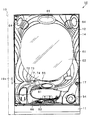
樹脂ベース21の中央部には略楕円形状の窓孔23が形成されている。樹脂ベース21には遊技盤24が着脱可能に取り付けられている。遊技盤24は合板よりなり、遊技盤24の前面に形成された遊技領域が樹脂ベース21の窓孔23を通じて内枠13の前面側に露出した状態となっている。
A substantially
ここで、遊技盤24の構成を図4に基づいて説明する。
Here, the structure of the
遊技盤24には、一般入賞口31,可変入賞装置32、下作動口34及びスルーゲート35が設けられているとともに、上作動口33を有する可変表示ユニット36が設けられている。一般入賞口31、可変入賞装置32及び作動口33,34に遊技球が入ると、それが遊技盤24の背面側に配設された検知センサ(図示略)により検知され、その検知結果に基づいて所定数の賞球の払い出しが実行される。その他に、遊技盤24の最下部にはアウト口37が設けられており、各種入賞口等に入らなかった遊技球はアウト口37を通って遊技領域から排出される。また、遊技盤24には、遊技球の落下方向を適宜分散、調整等するために多数の釘38が植設されていると共に、風車等の各種部材(役物)が配設されている。なお、以下の説明では、一般入賞口31や可変入賞装置32等といった特典付与対象となる入球部への入球と、アウト口37への入球とを区別するために、前者の入球を入賞とも称する。
The
可変表示ユニット36には、図柄を可変表示する図柄表示装置41が設けられているとともに、図柄表示装置41を囲むようにしてセンターフレーム42が配設されている。
The
センターフレーム42は、図柄表示装置41の上方及び左右の側方を囲む屋根ユニット171と、図柄表示装置41の下方に配設されたステージユニット172とを備えている。屋根ユニット171には、当該屋根ユニット171の上枠部に球入口173を有し当該球入口173に入った遊技球をステージユニット172上に導く一対のステージ誘導通路(ワープ通路)が形成されている。球入口173に遊技球が入ることにより、その遊技球がステージユニット172上に誘導される。但し、球入口173の周辺には複数の釘38が配設されており、球入口173への入球が頻繁に発生しないように構成されている。
The
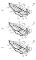
ステージユニット172はその上面に、図5に示すように、遊技球が転動可能な転動面174を有している。転動面174は、遊技球2個分程度の幅を有し、中央部を中心として左右対称な滑らかな流線形状となっている。具体的には、転動面174は、中央部が上方に盛り上がった山部175となっており、その左右は下方に凹んだ谷部176となっており、また左右両端は中央部よりも上方に位置する。
As shown in FIG. 5, the
谷部176は、前方に向けて下方に傾斜した形状をなしている。十分に減速された状態で谷部176上に到達した遊技球は、図5(a)に示すように、谷部176の傾斜により誘導されて、谷部176の前縁からステージユニット172の下方に排出される。
The
また、山部175の頂部には、前後方向に延び、前方に向けて下方に傾斜した形状をなす前方誘導路177と、前後方向に延び、後方に向けて下方に傾斜した形状をなす後方誘導路178とが一体形成されている。十分に減速された状態で前方誘導路177上に到達した遊技球は、図5(b)に示すように、当該前方誘導路177の傾斜により誘導されて、転動面174の前縁からステージユニット172の下方に排出される。一方、十分に減速された状態で後方誘導路178上に到達した遊技球は、図5(c)に示すように、当該後方誘導路178の傾斜により誘導されて、転動面174の後縁へ誘導される。そして、この誘導される位置には、上作動口33が設けられている。
In addition, a
上作動口33に遊技球が入ると、それが後述する検知センサにより検知され、その検知結果に基づいて所定数の賞球の払い出しが実行される。また、上作動口33への入球に基づいて、後述する主制御装置にて大当たり状態(特別遊技状態)を発生させるか否かの抽選が行われる。なお、かかる抽選は下作動口34への入球に基づいても同様に行われる。
When a game ball enters the upper working
図柄表示装置41は、液晶ディスプレイを備えた液晶表示装置として構成されており、作動口33,34への入賞をトリガとして図柄を可変表示する。図柄表示装置41は、後述する表示制御装置により表示内容が制御される。図柄表示装置41には、例えば左、中及び右に並べて図柄が表示され、これらの図柄が上下方向にスクロールされるようにして変動表示されるようになっている。そして、予め設定されている有効ライン上に所定の組合せの図柄が停止表示された場合には、特別遊技状態(以下、大当たりという)が発生することとなる。なお、図柄表示装置41としては液晶表示装置が設けられているが、これに限定されることはなく、有機EL表示装置、プラズマ表示装置及びCRTなどを用いてもよい。
The
センターフレーム42の上部には、第1特定ランプ部43及び第2特定ランプ部44が設けられている。また、センターフレーム42の上部及び下部にはそれぞれ保留ランプ部45,46が設けられている。下側の保留ランプ部45は、図柄表示装置41及び第1特定ランプ部43に対応しており、遊技球が作動口33,34を通過した回数は最大4回まで保留され保留ランプ部45の点灯によってその保留個数が表示されるようになっている。上側の保留ランプ部46は、第2特定ランプ部44に対応しており、遊技球がスルーゲート35を通過した回数は最大4回まで保留され保留ランプ部46の点灯によってその保留個数が表示されるようになっている。
A first
第1特定ランプ部43では、作動口33,34への入賞をトリガとして所定の順序で発光色の切り替えが行われ、予め定められた色で停止表示された場合には大当たりが発生する。また、第2特定ランプ部44では、遊技球のスルーゲート35への入賞をトリガとして所定の順序で発光色の切り替えが行われ、予め定められた色で停止表示された場合には下作動口34に付随する電動役物34aが所定時間だけ開放状態となる。これにより、下作動口34への遊技球の入賞が可能となる。
In the first
可変入賞装置32は、通常は遊技球が入賞できない又は入賞し難い閉状態になっており、大当たりの際に遊技球が入賞しやすい所定の開放状態に切り換えられるようになっている。可変入賞装置32の開放態様としては、所定時間(例えば30秒間)の経過又は所定個数(例えば10個)の入賞を1ラウンドとして、複数ラウンド(例えば15ラウンド)を上限として可変入賞装置32が繰り返し開放されるものが一般的である。
The
ここで、本パチンコ機10では遊技盤24に、図4に示すように、異常検知手段として、磁気検知センサ105と、フォトセンサ106と、振動検知センサ107とが設けられている。
Here, in the
磁気検知センサ105は、球入口173周辺における遊技盤24の背面側に設置されている。上記のとおり球入口173は上作動口33が設けられたステージユニット172上への遊技球の誘導口となっているため、前扉枠14に設けられた窓パネルとしてのガラス62の前方において球入口173周辺に磁石を近づけ、不正に球入口173へと遊技球を誘導させようとする行為が想定される。これに対して、磁気検知センサ105が設けられていることにより、上記磁石を用いた不正行為が行われた場合に、それを検知することが可能となる。磁気検知センサ105は後述する主制御装置と電気的に接続されており、磁気検知センサ105の検知結果は主制御装置に入力される。この場合、磁気検知センサ105は、磁気を検知していない場合は非検知信号としてHIレベル信号を出力し、磁気を検知している場合は検知信号としてLOWレベル信号を出力する。
The
フォトセンサ106は、球入口173周辺における遊技盤24の前面側に設置されている。上記のように磁石を用いた不正行為が行われる場合、その行為を磁気検知センサ105では検知できないことが考えられる。これに対して、フォトセンサ106が設けられていることにより、球入口173周辺に相当するガラス62の前方において所定期間に亘って手などが待機された場合に、それを検知することが可能となる。フォトセンサ106は後述する主制御装置と電気的に接続されており、フォトセンサ106の検知結果は主制御装置に入力される。この場合、フォトセンサ106は、手などを検知していない場合は非検知信号としてHIレベル信号を出力し、手などを検知している場合には検知信号としてLOWレベル信号を出力する。なお、フォトセンサ106に代えて、測距センサを用いてもよい。また、上記信号の出力態様を逆に設定してもよい。
The
ちなみに、磁気検知センサ105及びフォトセンサ106の位置は、上記のものに限定されることはなく、例えば、上記磁石を用いて一般入賞口31への入賞を不正に行わせようとする不正行為を抑制すべく、一般入賞口31周辺に磁気検知センサ105及びフォトセンサ106を配置してもよい。また、上記信号の出力態様を逆に設定してもよい。また、上作動口33が可変表示ユニット36の下方に配置された構成においては、その周辺に磁気検知センサ105及びフォトセンサ106を配置してもよい。
Incidentally, the positions of the
振動検知センサ107は、遊技盤24の背面側に設置されている。上記のとおりステージユニット172の転動面174上を転動する遊技球は、基本的に十分に減速された状態で後方誘導路178上に到達することで、上作動口33へ誘導される。この場合、前扉枠14を叩く等してパチンコ機10に振動を与えることにより、転動面174上を転動している遊技球を強引に上作動口33に入れさせようとする行為が想定される。これに対して、振動検知センサ107が設けられていることにより、上記振動を与えることによる不正行為が行われた場合に、それを検知することが可能となる。振動検知センサ107は後述する主制御装置と電気的に接続されており、振動検知センサ107の検知結果は主制御装置に入力される。この場合、振動検知センサ107は、振動を検知していない場合は非検知信号としてHIレベル信号を出力し、振動を検知している場合には検知信号としてLOWレベル信号を出力する。なお、振動検知センサ107の配置位置は上記のものに限定されることはなく、前扉枠14、樹脂ベース21又は裏パックユニット15に振動検知センサ107を配置してもよい。また、上記信号の出力態様を逆に設定してもよい。
The
遊技盤24には、内レール部51と外レール部52とが取り付けられており、これら内レール部51と外レール部52とにより誘導レールが構成され、遊技球発射機構53から発射された遊技球が遊技領域の上部に案内されるようになっている。遊技球発射機構53は、図2に示すように、樹脂ベース21における窓孔23の下方に取り付けられており、前扉枠14に設けられた発射ハンドル54が操作されることにより遊技球の発射動作が行われる。
An
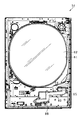
内枠13の前面側全体を覆うようにして前扉枠14が設けられている。前扉枠14には、図1に示すように、遊技領域のほぼ全域を前方から視認することができるようにした窓部61が形成されている。窓部61は、略楕円形状をなし、透明性を有するガラス62が嵌め込まれている。窓部61の周囲には、各種ランプ等の発光手段が設けられている。当該各種ランプ部の一部としてエラー表示ランプ部63が窓部61の上方に設けられている。また、エラー表示ランプ部63の左右両側には、遊技状態に応じた効果音などが出力されるスピーカ部64が設けられている。
A
前扉枠14における窓部61の下方には、手前側へ膨出した上側膨出部65と下側膨出部66とが上下に並設されている。上側膨出部65には、図1に示すように、球貸操作装置71が配設されている。球貸操作装置71には球貸ボタン72と、返却ボタン73と、度数表示部74とが設けられている。球貸装置Yにカード等を挿入した状態で、球貸操作装置71によって球貸し操作、カード返却操作及びカード度数の確認を行うことができる。すなわち、球貸ボタン72は、カード等(記録媒体)に記録された情報に基づいて貸出球を得るために操作されるものであり、カード等に残額が存在する限りにおいて貸出球が払い出される。返却ボタン73は、球貸装置Yに挿入されたカード等の返却を求める際に操作される。度数表示部74はカード等の残額情報を表示するものである。
Below the
また、上側膨出部65内側には上方に開口した上皿81が設けられており、下側膨出部66内側には同じく上方に開口した下皿82が設けられている。上皿81は、後述する払出装置より払い出された遊技球を一旦貯留し、一列に整列させながら遊技球発射機構53側へ導くための機能を有する。また、下皿82は、上皿81内にて余剰となった遊技球を貯留する機能を有する。
An
ここで、本パチンコ機10では、前扉枠14に対して窓部61、上皿81、及び下皿82が一体化されている。従来のパチンコ機においては、少なくとも窓部と下皿とがそれぞれ別ユニットとして設けられており、窓部が下皿に対して独立して回動可能となっていたため、パチンコ機の前面部には上記各ユニット間に境界が生じていた。この場合、当該境界から不正具などを挿入して行う不正行為が想定される。また、かかる不正行為を抑制すべく各ユニット間の境界に対して不正抑制構造を設けることもできるが、そうすると構成の複雑化を招いてしまう。さらに、パチンコ機の前面部において境界が生じるのは、デザイン上好ましくない。これに対して、上記のとおり前扉枠14に対して窓部61、上皿81及び下皿82が一体化されているので、窓部61と下皿82との間に境界が生じることはなく、上記不都合が抑制される。
Here, in the
上皿81及び下皿82には、裏パックユニット15の払出装置114(図7参照)から払い出された遊技球が前扉枠14の背面に設けられた通路形成ユニット83を通じて排出される。通路形成ユニット83は、図6に示すように、上皿81に通じる前扉側上皿通路84と、下皿82に通じる前扉側下皿通路85とが形成されている。
The game balls paid out from the payout device 114 (see FIG. 7) of the
前扉側上皿通路84及び前扉側下皿通路85は、それぞれ内枠13に設けられた各内枠側通路(図示略)に連通されている。また、これら各内枠側通路は、裏パックユニット15に設けられた払出装置114に連通されている。この場合に、裏パックユニット15において払出装置114の下流側には後述する遊技球分配部が設けられており、上皿81が満タン状態となり遊技球分配部の位置から上皿81の入口まで遊技球が充填された状態となった場合に、それ以降に払出装置114から払い出された遊技球が遊技球分配部にて下皿82側に振り分けられる。
The front door side
前扉枠14を内枠13に対して前方に回動させる場合には、前扉側上皿通路84及び前扉側下皿通路85が各内枠側通路から離間されることとなる。この場合に、各内枠側通路は内枠13に設けられた開閉部材86によって閉鎖される。開閉部材86は、図2に示すように、その下端に設けられた支軸87により前後方向に回動可能に支持されており、さらに各内枠側通路を閉鎖する前方位置に付勢する図示しない付勢部材が設けられている。したがって、前扉枠14を内枠13に対して開いた状態では開閉部材86が図示の如く起き上がり、各内枠側通路を閉鎖する。なお、前扉枠14を閉鎖した状態では、前扉枠14の通路形成ユニット83により開閉部材86が付勢力に抗して押し開けられる。
When the
通路形成ユニット83には、図6に示すように、前扉側下皿通路85を通る遊技球を検知するように満タン検知センサ88が設けられている。満タン検知センサ88は、磁気検知タイプの近接センサにて構成されており、検知範囲内を遊技球が通過する際の磁界(又は磁場)の変化が検知されて電気信号として出力される。なお、満タン検知センサ88は磁気検知タイプの近接センサに限定されることはなく、遊技球を検知することができるのであれば任意であり、例えば、フォトセンサやリミットセンサなどを用いてもよい。
As shown in FIG. 6, the
満タン検知センサ88は裏パックユニット15の払出制御装置141(図7参照)に対して電気信号を出力する。具体的には、遊技球を検知していない状態ではLOWレベル信号を出力し、遊技球を検知している状態ではHIレベル信号を出力する。なお、これに限定されることはなく、遊技球を検知していない状態ではHIレベル信号を出力し、遊技球を検知している状態ではLOWレベル信号を出力する構成としてもよく、また遊技球を検知している状態においてのみ電気信号を出力する構成としてもよい。
The full
払出制御装置141では、満タン検知センサ88の検知結果に基づいて下皿82が満タン状態であるか否かを特定し、下皿82が満タン状態であると特定した場合、払出装置114による遊技球の払出を停止する。これにより、下皿82が満タン状態となり、前扉側下皿通路85において満タン検知センサ88の位置まで遊技球が連なった場合には、それ以上の遊技球の払出が停止される。
In the dispensing
次に、遊技機本体12の背面側の構成について説明する。なお、以下の説明では、図3に加え図7を適宜参照する。図7は裏パックユニット15の正面図である。
Next, the configuration on the back side of the gaming machine
図3に示すように、内枠13(具体的には、遊技盤24)の背面には、主制御装置91及び音声ランプ制御装置92が搭載されている。主制御装置91は、遊技の主たる制御を司る機能(主制御回路)と、電源を監視する機能(電断監視回路)とを有する主制御基板を具備しており、当該主制御基板が透明樹脂材料等よりなる基板ボックス93に収容されて構成されている。音声ランプ制御装置92は、主制御装置91からの指示に従い音声やランプ表示、及び図示しない表示制御装置の制御を司る音声ランプ制御基板を具備しており、音声ランプ制御基板が透明樹脂材料等よりなる基板ボックス94に収容されて構成されている。
As shown in FIG. 3, a
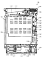
裏パックユニット15は、図7に示すように、裏パック101を備えており、当該裏パック101に対して、払出機構部102及び制御装置集合ユニット103が取り付けられている。裏パック101は透明性を有する合成樹脂により形成されており、主制御装置91や音声ランプ制御装置92などを後方から覆うように、後方に突出し略直方体形状をなす保護カバー部104を有している。
As shown in FIG. 7, the
払出機構部102は、保護カバー部104を迂回するようにして配設されている。払出機構部102には、裏パック101の最上部に配置され遊技ホールの島設備から供給される遊技球が逐次補給されるタンク111と、タンク111の下方から下流側に向けて緩やかに傾斜するタンクレール112と、タンクレール112の下流側に連結され上下方向に延びるケースレール113と、ケースレール113の最下流部に設けられた払出装置114と、を備えている。
The
ケースレール113には、当該ケースレール113内の通路を通じてタンク111から払出装置114まで連なった遊技球を検知するように球無検知センサ115が設けられている。球無検知センサ115は、磁気検知タイプの近接センサにて構成されており、検知範囲内を遊技球が通過する際の磁界の変化が検知されて電気信号として出力される。なお、球無検知センサ115は磁気検知タイプの近接センサに限定されることはなく、遊技球を検知することができるのであれば任意であり、例えば、フォトセンサやリミットセンサなどを用いてもよい。
The
球無検知センサ115は払出制御装置141に対して電気信号を出力する。具体的には、遊技球を検知していない状態ではLOWレベル信号を出力し、遊技球を検知している状態ではHIレベル信号を出力する。なお、これに限定されることはなく、遊技球を検知していない状態ではHIレベル信号を出力し、遊技球を検知している状態ではLOWレベル信号を出力する構成としてもよく、また遊技球を検知している状態においてのみ電気信号を出力する構成としてもよい。
The
払出制御装置141では、球無検知センサ115の検知結果に基づいてタンク111が球無状態であるか否かを特定し、タンク111が球無状態であると特定した場合、払出装置114による遊技球の払出を停止する。これにより、タンク111が球無状態であるにも関わらず、払出装置114が動作し続けることが防止される。
In the
また、ケースレール113には、球抜き操作スイッチ116が設けられている。例えば、タンク111に貯留されている遊技球のパチンコ機10外への排出に際して、ケースレール113にある遊技球も全て排出する場合に球抜き操作スイッチ116が押され、ケースレール113及びその下流側に貯留されている遊技球の排出が可能となる。
The
払出装置114では遊技球の払出が実行される。ここで、払出装置114の構成について図8を用いて説明する。図8は払出装置114内部に形成された通路構造を示す縦断面図である。
In the
払出装置114は合成樹脂製のハウジング121を備えており、当該ハウジング121にはケースレール113から供給される遊技球が通過する払出通路122が形成されている。払出通路122の中間部分には通路幅が左右に広がった収容部123が設けられており、当該収容部123に回転体124が収容されている。回転体124はその中心が払出モータ125の出力軸125aに固定されている。
The
払出モータ125は、ステッピングモータにより構成されており、出力軸125aは所定方向(図8で見て時計回り方向又は反時計回り方向)に回転駆動される。払出モータ125は、払出制御装置141内に設けられたモータドライバを通じて同じく払出制御装置141内に設けられたMPUによって駆動制御される。具体的には、MPUからモータドライバに1パルスの駆動信号(励磁信号又は励磁パルスとも言う。以下同様)が与えられることにより、払出モータ125の励磁状態が切り換えられ、出力軸125aが1step進む。払出モータ125は、MPUから60パルスの駆動信号が与えられることで出力軸125aが60step進み、当該出力軸125aが1回転するように設定されている。そして、出力軸125aが1回転することで、すなわち払出制御装置141のMPUから60パルスの駆動信号が出力されることにより、回転体124が1回転する。
The
回転体124の周縁には、180°間隔で2箇所に、凹部124aが形成されている。凹部124aは、曲面状となっておりその曲率は遊技球の曲率と同程度となっている。また、回転体124の周縁における凹部124a間の部位と収容部123の通路壁との間の距離が遊技球の直径寸法よりも短くなっているのに対して、凹部124aと収容部123の通路壁との間の距離は遊技球の直径寸法よりも長くなっている。これにより、払出通路122を流下してきた遊技球が回転体124の凹部124aに到達すると、当該遊技球は回転体124の回転に伴って下流側に導出される。
On the periphery of the
ここで、上記のとおり払出制御装置141のMPUから60パルスの駆動信号が出力されることにより回転体124が1回転するため、回転体124に180°間隔で2箇所に凹部124aが形成された構成においては、1個の遊技球が回転体124によって下流側に導出されてから払出モータ125に30パルスの駆動信号を与えることにより、次の遊技球が下流側に導出される。なお、回転体124が1回転するのに必要な駆動信号のパルス数や、1個の遊技球が下流側に導出されてから次の遊技球が下流側に導出されるまでに要する駆動信号のパルス数は、上記のものに限定されることはなく任意である。
Here, as described above, since the 60-pulse drive signal is output from the MPU of the
払出通路122には、収容部123よりも下流側の位置に略平板状をした払出球検知センサ126が設置されている。払出球検知センサ126は、周知の電磁誘導型の近接センサにて構成されており、検知部127の貫通孔127aを遊技球が通過したことによる磁界の変化を電気信号に変換して出力する。払出球検知センサ126は払出制御装置141と電気的に接続されており、払出制御装置141は当該払出球検知センサ126により、回転体124の下流側へと導出された遊技球の数が確認できるようになっている。
A payout
払出装置114より払い出された遊技球は、裏パック101に設けられた遊技球分配部128に供給される。遊技球分配部128は、複数の開口部が左右方向に並設されており、内側の開口部が上述した前扉側上皿通路84を介して上皿81に通じており、外側の開口部が上述した前扉側下皿通路85を介して下皿82に通じている。かかる遊技球分配部128によって、払出装置114より払い出された遊技球は、上皿81又は下皿82の何れかに分配される。
The game balls paid out from the
払出機構部102には、裏パック基板131が設置されている。裏パック基板131には、例えば交流24ボルトの主電源が供給され、電源操作部としての電源スイッチ132の切替操作により電源ON又は電源OFFとされるようになっている。
A
裏パック101には、その右上部に外部端子板133が設けられている。外部端子板133には、内枠13の開放時に信号出力するための出力端子、前扉枠14の開放時に信号出力するための出力端子、大当たり中(特別遊技状態中)に信号出力するための出力端子、及び第1特定ランプ部(特定表示部)43における1遊技回分の発光色の切換表示が終了した場合に信号出力するための出力端子が設けられている。そして、これらの出力端子を通じて、遊技ホール側の管理装置(又はホールコンピュータ)に対してパチンコ機10側の状態に関する信号が出力される。
The
ここで、第1特定ランプ部43に対応した出力端子は、1遊技回が終了した場合にそれを示す信号出力を行う機能を有しているのであれば、発光色の切換表示が終了した場合に信号出力するものでなくてもよい。この場合に、1遊技回とは、作動口(抽選契機入球部)33,34への一の入賞に基づいて抽選が行われた場合に、その抽選結果を示す表示が開始されてから終了するまでのことをいう。なお、第1特定ランプ部43に対応した出力端子は、1遊技回が実行されことを特定可能な信号を出力するものであればよく、例えば、1遊技回が実行中である場合に信号出力を行う構成や1遊技回が開始した場合に信号出力を行う構成としてもよい。
Here, if the output terminal corresponding to the first
また、大当たり中に上記遊技回が開始されることはなく、基本的には、大当たり中の信号出力と、1遊技回が終了した場合の信号出力とが同時に起こることはない。但し、後述する不正発生が主制御装置にて特定された場合には、これら信号出力が同時に行われる。これにより、遊技ホール側の管理装置では、これら信号を同時に入力した場合、パチンコ機10側において不正が検知されていることが把握される。
Further, the game times are not started during the jackpot, and basically, the signal output during the jackpot and the signal output when one game round is completed do not occur simultaneously. However, when the occurrence of fraud, which will be described later, is specified by the main control device, these signal outputs are performed simultaneously. Thereby, in the management apparatus of the game hall side, when these signals are input simultaneously, it is grasped that fraud is detected on the
つまり、外部端子板133には、同時に発生することのない第1状況と第2状況とに対して個別に第1出力端子と第2出力端子が設けられているとともに、上記第1状況及び第2状況のいずれでもない第3状況が発生した場合には、第1出力端子及び第2出力端子の両方から信号出力を行うようにしている。これにより、外部端子板133の端子数を少なく抑えることが可能となり、パチンコ機10のコスト低減が図られるとともに、遊技ホール側の管理装置においても入力端子数の削減が図られることに伴ってコストの削減が図られる。なお、上記第3状況を、上記のような不正を検知した状況に代えて、予め定められた異常を検知した状況としてもよい。
That is, the external
裏パック101には、外部端子板133よりも外側に、内枠13が開放されているか否か(又は閉鎖されているか否か)を検知する内枠開放スイッチ134が設けられている。外枠11に対して内枠13を閉じた状態では当該スイッチ134の金属接点が閉じて内枠13の閉鎖が検知され、外枠11に対して内枠13を開いた状態では金属接点が開いて内枠13の開放が検知されるようになっている。
The
ちなみに、内枠開放スイッチ134は、内枠13が開放状態の場合に主制御装置91に対して内枠開放信号としてHIレベル信号を出力し、内枠13が閉鎖状態の場合にはLOWレベル信号を出力する。但し、信号の出力態様はこれに限定されることはなく、HIレベル信号とLOWレベル信号との関係が逆であってもよい。
Incidentally, the inner
裏パック101の下端に制御装置集合ユニット103が取り付けられている。制御装置集合ユニット103は、払出制御装置141と電源及び発射制御装置142と球貸用接続端子板143とを備えている。これら払出制御装置141と電源及び発射制御装置142と球貸用接続端子板143は、払出制御装置141及び球貸用接続端子板143がパチンコ機10後方となり電源及び発射制御装置142がパチンコ機10前方となるように前後に重ねて配置されている。なお、制御装置集合ユニット103には、上述した排出通路が形成されている。
A control device
払出制御装置141は、払出装置114を制御する払出制御基板が透明樹脂材料等よりなる基板ボックス144に収容されて構成されている。また、払出制御装置141には状態復帰スイッチ145が設けられている。例えば、払出装置114における球詰まり等、払出エラーの発生時において状態復帰スイッチ145が押されると、球詰まりの解消が図られるようになっている。また、払出制御基板には7セグ表示器146が搭載されており、内枠13を外枠11に対して開放することで、基板ボックス144を通じて7セグ表示器146の表示内容が視認可能となっている。
The
電源及び発射制御装置142は、各種制御装置等で要する所定の電力が生成されるとともに遊技者による発射ハンドル54の操作に伴う遊技球の打ち出しの制御を行う電源及び発射制御基板が透明樹脂材料等よりなる基板ボックス147に収容されて構成されている。また、電源及び発射制御装置142にはRAM消去スイッチ148が設けられている。本パチンコ機10は各種データの記憶保持機能を有しており、万一電断が発生した際でも電断時の状態を保持し、電断からの復帰の際には電断時の状態に復帰できるようになっている。したがって、例えば遊技ホールの営業終了の場合のように通常手順で電源を遮断すると遮断前の状態が記憶保持されるが、RAM消去スイッチ148を押しながら電源を投入すると、RAMデータが初期化されるようになっている。
The power source and launch
球貸用接続端子板143は、球貸装置Y、払出制御装置141及びパチンコ機10前面の球貸操作装置71に電気的に接続され、主として遊技者による球貸し操作の指令を取り込んでそれを払出制御装置141に出力するものである。
The ball lending
<パチンコ機10の電気的構成>
次に、パチンコ機10の電気的構成について、図9のブロック図に基づいて説明する。図9では、電力の供給ラインを二重線矢印で示し、信号ラインを実線矢印で示す。
<Electric configuration of
Next, the electrical configuration of the
主制御装置91には、主制御基板201と電断監視基板(停電監視基板)203とが設けられている。主制御基板201には、MPU211が搭載されている。MPU211には、当該MPU211により実行される各種の制御プログラムや固定値データを記憶したROM(不揮発性記憶手段)212と、そのROM212内に記憶される制御プログラムの実行に際して各種のデータ等を一時的に記憶するためのメモリであるRAM(揮発性記憶手段)213と、割込回路やタイマ回路、データ入出力回路などの各種回路が内蔵されている。なお、MPU211、ROM212及びRAM213の一部又は全部をそれぞれ別のチップとして設けてもよい。
The
MPU211には、入力ポート211a及び出力ポートがそれぞれ設けられている。なお、入出力ポートを備え、MPU211において入出力が適宜変更される構成としてもよい。これは、後述する他のMPUにおいても同様である。
The
MPU211の入力ポート211aには、電断監視基板203、払出制御装置141に設けられた払出制御基板222及びその他図示しないセンサ群などが接続されている。この場合に、電断監視基板203には電源及び発射制御基板221が接続されており、MPU211には電断監視基板203を介して電力が供給される。
Connected to the
上記スイッチ群の一部として、磁気検知センサ105、フォトセンサ106及び振動検知センサ107の各検知結果(各検知信号)がMPU211に入力されるとともに、前扉枠開放スイッチ22及び内枠開放スイッチ134の各検知結果(各検知信号)がMPU211に入力される。この場合、RAM213には、磁気検知センサ105、フォトセンサ106及び振動検知センサ107の検知結果に基づいて不正の発生の有無を確認する上で用いられる不正確認用計測手段としての不正確認カウンタエリア215と、不正の発生を確認した場合にその確認した旨の情報である不正確認情報としての不正検知フラグを格納するための不正検知フラグ格納エリア(不正検知情報記憶手段)216とが設けられている。
As part of the switch group, the detection results (detection signals) of the
また、スイッチ群の一部として、作動口33,34及び可変入賞装置32などといった入球部に設けられた複数の検知センサが接続されており、主制御装置91のMPU211において入球部の入球判定が行われる。また、MPU211では、入球部のうち、作動口33,34への入球に基づいて大当たり発生判定を実行する。
In addition, as a part of the switch group, a plurality of detection sensors provided in the ball entrance such as the
ここで、MPU211にて大当たり発生判定を行う上での電気的な構成について図10を用いて説明する。
Here, an electrical configuration for determining the occurrence of a jackpot in the
MPU211は遊技に際し各種カウンタ情報を用いて、大当たり抽選、第1特定ランプ部43の発光色の設定や、図柄表示装置41の図柄表示の設定などを行うこととしており、具体的には、大当たりの抽選に使用する大当たり乱数カウンタC1と、確変大当たりや通常大当たり等の大当たり種別を判定する際に使用する大当たり種別カウンタC2と、図柄表示装置41が外れ変動する際のリーチ抽選に使用するリーチ乱数カウンタC3と、大当たり乱数カウンタC1の初期値設定に使用する乱数初期値カウンタCINIと、第1特定ランプ部43に表示される色の切り替えを行う期間及び図柄表示装置41における図柄の変動表示時間を決定する変動種別カウンタCSとを用いることとしている。
The
カウンタC1〜C3,CINI,CSは、その更新の都度前回値に1が加算され、最大値に達した後0に戻るループカウンタとなっている。各カウンタは短時間間隔で更新され、その更新値がRAM213の所定領域に設定されたカウンタ用バッファに適宜格納される。RAM213には、1つの実行エリアと4つの保留エリア(保留第1〜第4エリア)とからなる保留球格納バッファが設けられており、これらの各エリアには、作動口33,34への遊技球の入球履歴に合わせて、大当たり乱数カウンタC1、大当たり種別カウンタC2及びリーチ乱数カウンタC3の各値が時系列的に格納されるようになっている。
Each of the counters C1 to C3, CINI, and CS is a loop counter that adds 1 to the previous value every time it is updated and returns to 0 after reaching the maximum value. Each counter is updated at short time intervals, and the updated value is appropriately stored in a counter buffer set in a predetermined area of the
各カウンタについて詳しくは、大当たり乱数カウンタC1は、例えば0〜676の範囲内で順に1ずつ加算され、最大値(つまり676)に達した後0に戻る構成となっている。特に大当たり乱数カウンタC1が1周した場合、その時点の乱数初期値カウンタCINIの値が当該大当たり乱数カウンタC1の初期値として読み込まれる。なお、乱数初期値カウンタCINIは、大当たり乱数カウンタC1と同様のループカウンタである(値=0〜676)。大当たり乱数カウンタC1は定期的に更新され、遊技球が作動口33,34に入球したタイミングでRAM213の保留球格納バッファに格納される。
For details of each counter, the jackpot random number counter C1 is configured such that, for example, 1 is sequentially added within a range of 0 to 676, and after reaching the maximum value (that is, 676), it returns to 0. In particular, when the jackpot random number counter C1 makes one round, the value of the random number initial value counter CINI at that time is read as the initial value of the jackpot random number counter C1. The random number initial value counter CINI is a loop counter similar to the big hit random number counter C1 (value = 0 to 676). The big hit random number counter C1 is periodically updated, and stored in the reserved ball storage buffer of the
大当たり種別カウンタC2は、0〜49の範囲内で順に1ずつ加算され、最大値(つまり49)に達した後0に戻る構成となっている。そして、本実施の形態では、大当たり種別カウンタC2によって、大当たりが終了した後に、確変状態とするか通常状態とするかを決定することとしている。大当たり種別カウンタC2は定期的に更新され、遊技球が作動口33,34に入球したタイミングでRAM213の保留球格納バッファに格納される。
The jackpot type counter C2 is incremented by 1 within a range of 0 to 49, and reaches a maximum value (that is, 49) and then returns to 0. In the present embodiment, the jackpot type counter C2 determines whether the probability change state or the normal state is set after the jackpot is finished. The jackpot type counter C2 is periodically updated, and stored in the reserved ball storage buffer of the
リーチ乱数カウンタC3は、例えば0〜238の範囲内で順に1ずつ加算され、最大値(つまり238)に達した後0に戻る構成となっている。リーチ乱数カウンタC3は定期的に更新され、遊技球が作動口33,34に入球したタイミングでRAM213の保留球格納バッファに格納される。
For example, the reach random number counter C3 is incremented one by one within a range of 0 to 238, for example, and reaches a maximum value (that is, 238) and then returns to 0. The reach random number counter C3 is periodically updated and stored in the reserved ball storage buffer of the
変動種別カウンタCSは、例えば0〜240の範囲内で順に1ずつ加算され、最大値(つまり240)に達した後0に戻る構成となっている。変動種別カウンタCSによって、第1特定ランプ部43に表示される色の切り替えを行う期間としての切替表示時間が決定される。この切替表示時間は、図柄表示装置41の図柄の変動表示時間に相当する。変動種別カウンタCSは、後述する通常処理が1回実行される毎に1回更新され、当該通常処理内の残余時間内でも繰り返し更新される。そして、第1特定ランプ部43に表示される色の切り替え開始時及び図柄表示装置41による図柄の変動開始時における変動パターン決定に際して変動種別カウンタCSのバッファ値が取得される。
For example, the variation type counter CS is incremented one by one within a range of 0 to 240, for example, and reaches a maximum value (that is, 240) and then returns to 0. The switching display time as a period for switching the color displayed on the first
なお、1遊技回の開始に際しては、主制御基板201のMPU211にて、保留球格納エリアに格納されている各カウンタC1〜C3,CSの値を用いて大当たり抽選や第1特定ランプ部43に表示される色の切り替え時間が決定されるが、ここで決定された抽選結果の情報や切り替え時間の情報は遊技回用コマンドとして音声ランプ制御装置92に送信される。音声ランプ制御装置92では、当該遊技回用コマンドに基づいて、図柄表示装置41における変動パターンやリーチ発生の有無といった該当する遊技回の演出内容を決定する。
At the start of one game round, the
また、上記各カウンタ以外にも、下作動口34の電動役物34aを開放状態とするか否かの抽選に用いられる第2特定ランプ乱数カウンタが設けられており、スルーゲート35への入賞が発生したタイミングでその時点での第2特定ランプ乱数カウンタの値が取得され、その取得した値に基づいて電動役物34aを開放状態とするか否かの抽選が実行される。
In addition to the above counters, there is provided a second specific lamp random number counter used for a lottery to determine whether or not the electric accessory 34a of the lower working
図9の説明に戻り、MPU211の出力ポートには、電断監視基板203、払出制御基板222及び中継端子板223が接続されている。払出制御基板222には、賞球コマンドなどといった各種コマンドが出力される。中継端子板223を介して主制御基板201から音声ランプ制御装置92に設けられた音声ランプ制御基板224に対して上記遊技回用コマンドなどが出力される。
Returning to the description of FIG. 9, the power
ちなみに、MPU211には、NMI端子が設けられているが、当該NMI端子には外部機器が接続されていない。但し、このように外部機器が接続されていない構成であっても、ノイズ等の影響でNMI端子に何らかの信号が入力されてしまうことが想定される。この場合、MPU211においてNMI割込み処理が起動されることとなるが、当該NMI割込み処理は何ら処理を実行することなく即座にリターンとなるように設定されている。具体的には、NMI端子に信号入力されると起動されるようにNMI割込み処理が設定されているとともに、当該NMI割込み処理の処理内容として当該NMI割込み処理を終了するためのリターン命令が記憶されている。よって、上記のようにノイズ等の影響でNMI端子に何らかの信号が入力されたとしても、その影響がほとんど生じないようになっている。なお、上記NMI端子を不具備としてもよい。
Incidentally, although the
電断監視基板203は、主制御基板201と電源及び発射制御基板221とを中継し、また電源及び発射制御基板221から出力される最大電圧である直流安定24ボルトの電圧を監視する。そして、この電圧が22ボルト以上の場合には、主制御基板201に対し非電断信号(第1情報)としてのHIレベル信号を出力(送信)し、この電圧が22ボルト未満になると電源遮断の発生と判断し、主制御基板201に対して電断信号(第2情報)としてのLOWレベル信号を出力(送信)する。主制御基板201では、このLOWレベル信号の入力を所定の態様で確認することにより、その確認結果に基づいて後述する電断時処理(停電時処理)を実行する。この場合、当該電断時処理を実行するか否かの判定を行う上で、主制御基板201のRAM213に設けられた電断確認用計測手段(停電確認用計測手段)としての電断確認カウンタエリア217と、電断発生情報記憶手段(停電発生情報記憶手段)としての電断フラグ格納エリア218が用いられる。
The power
払出制御基板222は、払出装置114により賞球などの払出制御を行うものである。演算装置であるMPU231は、そのMPU231により実行される制御プログラムや固定値データ等を記憶したROM232と、ワークメモリ等として使用されるRAM233とを備えている。なお、MPU231、ROM232及びRAM233の一部又は全部をそれぞれ別のチップとして設けてもよい。
The
払出制御基板222のMPU231には、入力ポート及び出力ポートがそれぞれ設けられている。MPU231の入力側には、主制御基板201、電源及び発射制御基板221、及び裏パック基板131が接続されている。また、MPU231の出力側には、主制御基板201及び裏パック基板131が接続されている。
The
電源及び発射制御基板221は、電入時用電源部221aと発射制御部221bとを備えている。電入時用電源部221aは、例えば、遊技ホール等における商用電源(外部電源)に接続されている。そして、その商用電源から供給される外部電力に基づいて主制御基板201や払出制御基板222等に対して各々に必要な動作電力を生成するとともに、その生成した動作電力を二重線矢印で示す経路を通じて主制御基板201や払出制御基板222等に対して供給する。その概要としては、電入時用電源部221aは、裏パック基板131を介して供給される交流24ボルト電源を取り込み、各種センサやモータ等を駆動するための直流+12V電力、ロジック用の直流+5V電力などを生成し、これら直流+12V電力、直流+5V電力を主制御基板201や払出制御基板222等に対して供給する。
The power and launch
発射制御部221bは、遊技者による発射ハンドル54の操作にしたがって遊技球発射機構53の発射制御を担うものであり、遊技球発射機構53は所定の発射条件が整っている場合に駆動される。
The launch control unit 221b is responsible for launch control of the game
また、電源及び発射制御基板221には、電断時用電源部221cが搭載されている。電断時用電源部221cはコンデンサからなり、パチンコ機10の電源がON状態の場合(外部電源からの電力供給が行われている場合)に電入時用電源部221aから供給される電力により充電される。また、パチンコ機10の電源がOFF状態の場合や商用電源における電断発生時といった電源遮断状態(外部電源からの電力供給が遮断されている場合)では、電断時用電源部221cから放電され主制御基板201のRAM213に対して記憶保持用電力が供給される。よって、かかる状況であっても、電断時用電源部221cから記憶保持用電力が供給されている間はRAM213に記憶された情報が消去されることなく記憶保持される。
The power source and launch
ちなみに、電断時用電源部221cの容量は比較的大きく確保されており、電源遮断前にRAM213に記憶されていた情報は所定の期間内(例えば、1日や2日)保持される。また、電断時用電源部221cは、コンデンサに限定されることはなく、バッテリや非充電式電池などであってもよい。非充電式電池の場合、パチンコ機10の電源がON状態の際に電断時用電源手段への充電を行う必要はないが、定期的に交換する必要が生じる。
Incidentally, the capacity of the
また、電源及び発射制御基板221には、上記電断時用電源部221cとは異なる電断時処理用電源部が設けられている。電源及び発射制御基板221では、直流安定24ボルトの電源が22ボルト未満になった後においても、電断時処理用電源部から放電することにより、後述する電断時処理の実行に十分な時間の間、制御系の駆動電源である5ボルトの出力を正常値に維持するように構成されている。これにより、主制御基板201などは、電断時処理を正常に実行し完了することができる。
The power supply and
音声ランプ制御基板224は、エラー表示ランプ部63やスピーカ部64、及び表示制御装置225を制御するものである。演算装置であるMPU241は、そのMPU241により実行される制御プログラムや固定値データ等を記憶したROM242と、ワークメモリ等として使用されるRAM243とを備えている。
The sound
音声ランプ制御基板224のMPU241には入力ポート及び出力ポートがそれぞれ設けられている。MPU241の入力側には中継端子板223に中継されて主制御基板201が接続されており、主制御基板201から出力される各種コマンドに基づいて、エラー表示ランプ部63、スピーカ部64、及び表示制御装置225を制御する。表示制御装置225は、音声ランプ制御基板224から入力する表示コマンドに基づいて図柄表示装置41を制御する。
The
<主制御基板201のMPU211における処理構成>
次に、主制御基板201のMPU211により実行される各制御処理を説明する。かかるMPU211の処理としては大別して、電源投入に伴い起動されるメイン処理と、メイン処理の通常処理に対して定期的に割り込んで起動されるタイマ割込み処理とがあり、説明の便宜上、はじめにタイマ割込み処理を説明し、その後メイン処理を説明する。
<Processing Configuration in
Next, each control process executed by the
なお、以下の説明では、遊技球の払出制御に関係する処理以外の処理について先ず説明し、その後に当該遊技球の払出制御に関係する処理について説明する。また、理解を容易なものとするために、主制御基板201のMPU211を主側MPU211といい、主制御基板201のRAM213を主側RAM213といい、払出制御基板222のMPU231を払出側MPU231といい、払出制御基板222のRAM233を払出側RAM233という。
In the following description, processes other than the processes related to the game ball payout control will be described first, and then the processes related to the game ball payout control will be described. In order to facilitate understanding, the
<タイマ割込み処理>
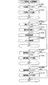
図11は、タイマ割込み処理を示すフローチャートである。タイマ割込み処理は、上記のとおり定期的に起動される。この場合、本実施の形態では2msec周期で起動されるように構成されているが、この周期は任意である。但し、当該タイマ割込み処理には、電断信号や不正検知信号の確認や、各種入賞の確認などといった短い周期で繰り返し実行すべき処理が設定されているため、これら以外の処理が設定されている後述する通常処理の繰り返し周期よりも短く設定されていることが好ましい。
<Timer interrupt processing>
FIG. 11 is a flowchart showing timer interrupt processing. The timer interrupt process is periodically started as described above. In this case, the present embodiment is configured to be activated at a cycle of 2 msec, but this cycle is arbitrary. However, since the timer interrupt processing is set to be executed repeatedly in a short cycle such as confirmation of power interruption signal or fraud detection signal, confirmation of various winnings, etc., other processing is set. It is preferably set shorter than the repetition period of the normal process described later.
タイマ割込み処理では、先ずステップS101にて、読み込み処理を実行する。読み込み処理では、一般入賞口31、可変入賞装置32、上作動口33、下作動口34及びスルーゲート35に対して個別に設けられた球検知センサから入力ポート211aに入力されている情報を確認し、その確認結果から各入球部への入球の有無を特定する。具体的には、任意の1回の処理にて遊技球を検知していないことに対応した信号(例えば、LOWレベル信号)の入力を確認し、その後の2回の処理にて遊技球を検知していることに対応した信号(例えば、HIレベル信号)の入力を連続して確認した場合に、その検知センサに対応した入球部において遊技球の入球が発生したと特定する。
In the timer interruption process, first, a reading process is executed in step S101. In the reading process, the information input to the
また、ステップS101の読み込み処理では、入力ポート211aに入力されている情報に基づいて電断の発生の有無を特定するための電断信号読み込み処理を実行する。電断信号読み込み処理について、図12のフローチャートを参照して説明する。
Further, in the reading process in step S101, a power interruption signal reading process for specifying whether or not a power interruption has occurred is executed based on information input to the
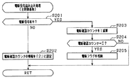
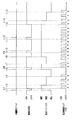
電断信号読み込み処理では、先ずステップS201にて、電断監視基板203から入力ポート211aに入力されている情報を確認し、その入力されている情報に基づいて電断信号を入力しているか否かを判定する。具体的には、電断監視基板203は、電源遮断の発生を検知していない場合には非電断信号としてのHIレベル信号を出力し、電源遮断の発生を検知している場合には電断信号としてのLOWレベル信号を出力する構成であるが、主制御基板201には反転回路が設けられており、電断監視基板203からHIレベル信号が出力されている場合には入力ポート211aの1ビットからなる電断確認用エリアには無しデータとしての「0」が格納され、電断監視基板203からLOWレベル信号が出力されている場合には入力ポート211aの電断確認用エリアには有りデータとしての「1」が格納される。ステップS201では、上記電断確認用エリアに「1」が格納されているか否かを判定する。
In the power interruption signal reading process, first, in step S201, the information input from the power
電断信号を入力していないと判定した場合には、ステップS202にて、主側RAM213における電断確認カウンタエリア217の情報を電断基準回数情報に設定する。具体的には、電断確認カウンタエリア217の情報を「2」に設定する。その後、本電断信号読み込み処理を終了する。
If it is determined that the power interruption signal is not input, the information of the power interruption
電断信号を入力していると判定した場合には、ステップS203にて、電断確認カウンタエリア217の情報を1減算する。続くステップS204では、電断確認カウンタエリア217が「0」となっているかを判定する。「0」となっていない場合には、そのまま本電断信号読み込み処理を終了する。「0」となっている場合には、ステップS205にて、主側RAM213における電断フラグ格納エリア218に電断発生情報(停電発生情報)としての電断フラグ(「1」の情報)を格納する。その後、本電断信号読み込み処理を終了する。
If it is determined that the power interruption signal is input, 1 is subtracted from the information in the power interruption
以上のとおり、本パチンコ機10では、主側MPU211において電断信号の入力を確認したとしても即座に電断の発生と特定するのではなく、複数回として設定された電断基準回(具体的には、2回)の確認タイミング、すなわち複数回として設定された電断基準回のタイマ割込み処理の起動回数に亘って継続して上記電断信号の入力を確認した場合に、電断が発生したと特定する。これにより、電気的なノイズ等の原因で電断信号を単発的に入力したとしても、それに対して電断の発生と特定されてしまうことを抑制することができる。なお、上記電断基準回の具体的な値は「2」に限定されることはなく、複数であれば任意であり、例えば、「3」又は「4」以上としてもよい。
As described above, in the
タイマ割込み処理(図11)の説明に戻り、信号読み込み処理を実行した後は、ステップS102にて、主側RAM213における不正検知フラグ格納エリア216に不正検知フラグが格納されているか否かを判定し、不正検知フラグが格納されていない場合には、磁気検知センサ105、フォトセンサ106及び振動検知センサ107の検知結果に基づいて不正の発生の有無を特定するとともに、不正の発生を特定した場合には上記不正検知フラグを格納するための不正監視処理を実行する。
Returning to the description of the timer interrupt process (FIG. 11), after executing the signal reading process, in step S102, it is determined whether or not the fraud detection flag is stored in the fraud detection
不正監視処理について、図13のフローチャートを参照して説明する。 The fraud monitoring process will be described with reference to the flowchart of FIG.
不正監視処理では、先ずステップS301にて不正系信号読み込み処理を実行する。不正系信号読み込み処理は、磁気検知センサ105、フォトセンサ106及び振動検知センサ107についてそれぞれ個別に実行される。各センサ105〜107についての不正系信号読み込み処理の処理構成は、確認対象となるセンサの種類が異なっているものの、処理構成は基本的に同一である。一の不正系信号読み込み処理について、図14のフローチャートを参照して説明する。
In the fraud monitoring process, an illegal signal reading process is first executed in step S301. The illegal system signal reading process is individually executed for the
不正系信号読み込み処理では、先ずステップS401にて、所定のセンサ、例えば磁気検知センサ105から入力ポート211aに入力されている情報を確認し、その入力されている情報に基づいて検知信号を入力しているか否かを判定する。具体的には、磁気検知センサ105は、磁気を検知していない場合には非検知信号としてのHIレベル信号を出力し、磁気を検知している場合には検知信号としてのLOWレベル信号を出力する構成であるが、主制御基板201には反転回路が設けられており、磁気検知センサ105からHIレベル信号が出力されている場合には入力ポート211aの1ビットからなる不正確認用エリアとしての磁気検知確認用エリアには無しデータとしての「0」が格納され、磁気検知センサ105からLOWレベル信号が出力されている場合には入力ポート211aの磁気検知確認用エリアには有りデータとしての「1」が格納される。ステップS401では、上記磁気検知確認用エリアに「1」が格納されているか否かを判定する。
In the illegal system signal reading process, first, in step S401, information input from a predetermined sensor, for example, the
不正の検知信号を入力していないと判定した場合には、ステップS402にて、主側RAM213の不正確認カウンタエリア215における今回の不正系信号読み込み処理に対応したカウンタエリアの情報を不正基準回数情報としての「2」の情報に設定する。つまり、不正確認カウンタエリア215には、磁気検知センサ105、フォトセンサ106及び振動検知センサ107のそれぞれに1対1で対応させてカウンタエリアが設定されており、例えば、磁気検知センサ105に対応する不正系信号読み込み処理においては、ステップS402にて、磁気検知センサ105に対応するカウンタエリアの情報を不正基準回数情報に設定する。その後、本不正系信号読み込み処理を終了する。
If it is determined that no fraud detection signal is input, in step S402, information on the counter area corresponding to the current fraud signal reading process in the fraud
不正の検知信号を入力していると判定した場合には、ステップS403にて、不正確認カウンタエリア215における各カウンタエリアのうち、今回の不正系信号読み込み処理に対応したカウンタエリアの情報を1減算する。続くステップS404では、ステップS403にて減算対象としたカウンタエリアが「0」となっているか否かを判定する。「0」となっていない場合には、そのまま本不正系信号読み込み処理を終了する。「0」となっている場合には、ステップS405にて、主側MPU211のレジスタに、今回の不正系信号読み込み処理に対応したセンサについての不正情報を記憶する。その後、本不正系信号読み込み処理を終了する。
If it is determined that a fraud detection signal is input, in step S403, 1 is subtracted from the counter area information corresponding to the current fraud signal reading process among the counter areas in the fraud
以上のとおり、本パチンコ機10では、主側MPU211において不正の検知信号の入力を確認したとしても即座に不正の発生と特定するのではなく、複数回として設定された不正基準回(具体的には、2回)の確認タイミング、すなわち複数回として設定された不正基準回のタイマ割込み処理の起動回数に亘って継続して上記不正の検知信号の入力を確認した場合に、不正が発生したと特定する。これにより、電気的なノイズ等の原因で上記検知信号を単発的に入力したとしても、それに対して不正の発生と特定されてしまうことを抑制することができる。
As described above, in the
不正監視処理(図13)の説明に戻り、不正系信号読み込み処理を実行した後は、ステップS302〜ステップS304の各種判定処理を実行する。つまり、ステップS302では、主側MPU211のレジスタに磁気検知センサ105についての不正情報が記憶されているか否かを判定し、ステップS303では、主側MPU211のレジスタにフォトセンサ106についての不正情報が記憶されているか否かを判定し、ステップS304では、主側MPU211のレジスタに振動検知センサ107についての不正情報が記憶されているか否かを判定する。
Returning to the description of the fraud monitoring process (FIG. 13), after executing the illegal signal reading process, various determination processes in steps S302 to S304 are performed. That is, in step S302, it is determined whether or not unauthorized information about the
上記全ての不正情報が記憶されておらず、ステップS302〜ステップS304の全てにおいて否定判定をした場合には、そのまま本不正監視処理を終了する。上記不正情報のいずれかが記憶されており、ステップS302〜ステップS304のいずれかにおいて肯定判定をした場合には、ステップS305以降の不正検知時処理を実行する。 If all of the fraud information is not stored and a negative determination is made in all of steps S302 to S304, the fraud monitoring process is terminated as it is. If any of the above fraud information is stored and an affirmative determination is made in any of steps S302 to S304, the fraud detection processing after step S305 is executed.
つまり、磁気検知センサ105についての不正情報が記憶されている場合とは、ガラス62の前方において球入口173に磁石を近づけ、不正に球入口173へと遊技球を誘導させようとする行為が行われていることを意味する。また、フォトセンサ106についての不正情報が記憶されている場合とは、球入口173周辺に相当するガラス62の前方に手などが待機されていることを意味する。また、振動検知センサ107についての不正情報が記憶されている場合とは、転動面174上を転動している遊技球を強引に上作動口33に入賞させようとする行為が行われていることを意味する。これらいずれかの不正情報が記憶されている場合には、ステップS305以降の不正検知処理を実行する。
In other words, when the illegal information about the
ステップS305では、主側RAM213の不正検知フラグ格納エリア216に不正検知フラグを格納する。不正検知フラグが格納されることにより、主側MPU211において、上記磁石を用いた不正行為が行われたこと、又は上記振動を与える不正行為が行われたことを特定することが可能となる。
In step S305, the fraud detection flag is stored in the fraud detection
続くステップS306では、不正検知コマンドを払出側MPU231及び音声ランプ制御基板224のMPU241のそれぞれに出力する。払出側MPU231では、主側MPU211から不正検知コマンドを入力することにより、遊技球の払出を制限するための処理を実行する。かかる制限するための処理については後に説明する。
In subsequent step S306, the fraud detection command is output to each of the
また、音声ランプ制御基板224のMPU241では、主側MPU211から不正検知コマンドを入力することにより、予め定められた不正用報知を実行するように各種報知部を駆動制御する。当該不正用報知の態様は任意であるが、例えば、エラー表示ランプ部63の点灯、スピーカ部64からの警告音の出力又は図柄表示装置41における不正検知画像の表示のいずれか1つ又は任意の組み合わせが考えられる。
Further, the
続くステップS307では、外部端子出力用ポートに不正情報を出力する。これにより、外部端子板133を通じて不正検知信号が遊技ホール側の管理装置に出力され、遊技ホール側の管理装置においてパチンコ機10に対して上記不正行為が行われたことを把握することができる。ここで、本パチンコ機10では既に説明したように、外部端子板133に不正検知信号用の出力端子が設けられていない。したがって、ここでは不正検知信号として、大当たり中用信号と1遊技回終了時用信号とが同時に出力される。その後、本不正監視処理を終了する。
In the subsequent step S307, illegal information is output to the external terminal output port. Thereby, a fraud detection signal is output to the management device on the game hall side through the external
タイマ割込み処理(図11)の説明に戻り、ステップS102にて不正検知フラグが格納されていると判定した場合、又はステップS103にて不正監視処理を実行した後は、ステップS104にて、乱数初期値カウンタCINIの更新を実行する。続くステップS105では、大当たり乱数カウンタC1、大当たり種別カウンタC2及びリーチ乱数カウンタC3の更新を実行する。 Returning to the description of the timer interrupt process (FIG. 11), if it is determined in step S102 that the fraud detection flag is stored, or after executing the fraud monitoring process in step S103, the initial random number is determined in step S104. Update the value counter CINI. In subsequent step S105, the big hit random number counter C1, the big hit type counter C2, and the reach random number counter C3 are updated.
その後、ステップS106にて不正検知フラグが格納されているか否かを判定する。不正検知フラグが格納されている場合にはそのまま本タイマ割込み処理を終了する。不正検知フラグが格納されていない場合にはステップS107にて始動入賞処理を実行する。 Thereafter, in step S106, it is determined whether or not a fraud detection flag is stored. If the fraud detection flag is stored, the timer interrupt process is terminated. If the fraud detection flag is not stored, a start winning process is executed in step S107.
始動入賞処理では、図15のフローチャートに示すように、先ずステップS501にて、RAM213の作動口フラグ格納エリアに作動口フラグが格納されているか否かを判定することにより、遊技球が作動口33,34に入賞(始動入賞)したか否かを判定する。なお、作動口フラグは、上記ステップS101にて上作動口33又は下作動口34への入賞が確認された場合に格納される。
In the start winning process, as shown in the flowchart of FIG. 15, first, in step S501, it is determined whether or not the operating port flag is stored in the operating port flag storage area of the
遊技球が作動口33,34に入賞したと判定すると、続くステップS502において、第1特定ランプ部43及び図柄表示装置41の作動保留球数Nが上限値(本実施の形態では4)未満であるか否かを判定する。作動口33,34への入賞があり、且つ作動保留球数N<4であることを条件にステップS503に進み、作動保留球数Nを1加算する。なお、ステップS503の処理後に作動口フラグを消去する。続くステップS504では、前記ステップS503で更新した大当たり乱数カウンタC1、大当たり種別カウンタC2及びリーチ乱数カウンタC3の各値を、RAM213の保留球格納エリアの空き記憶エリアのうち最初のエリアに格納する。そして、始動入賞処理の後、MPU211は本タイマ割込み処理を一旦終了する。
If it is determined that the game ball has won the operating holes 33, 34, in the subsequent step S502, the number N of the operation reserved balls of the first
ここで、上記のとおりタイマ割込み処理ではステップS102の処理及びステップS106の処理が実行されることにより、主側RAM213に不正検知フラグが格納されている場合には、不正監視処理及び始動入賞処理が実行されない。このうち、特に始動入賞処理が実行されないようにすることで、上記磁石を用いた不正行為又は上記振動を与える不正行為の発生を特定した場合には、仮に作動口33,34への入賞が発生したとしてもそれに対する大当たり抽選の実行を規制することができる。
As described above, in the timer interrupt process, when the fraud detection flag is stored in the
その一方、不正検知フラグが格納されている状況であるか否かに関係なくステップS101、ステップS104及びステップS105の各処理が実行されることにより、上記磁石を用いた不正行為又は上記振動を与える不正行為の発生を特定した場合であっても大当たり抽選に用いられる乱数カウンタの更新を維持することができるとともに、入力ポート211aの定期的な情報の確認を維持することができる。
On the other hand, regardless of whether or not the fraud detection flag is stored, the processes of step S101, step S104, and step S105 are executed to give an illegal act using the magnet or the vibration. Even when the occurrence of an illegal act is specified, it is possible to maintain the update of the random number counter used for the jackpot lottery and to maintain the periodic confirmation of the
<メイン処理>
次に、電源投入時のリセットに伴い起動されるメイン処理について、図16のフローチャートを用いて説明する。
<Main processing>
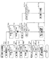
Next, the main process that is started upon reset at power-on will be described with reference to the flowchart of FIG.
先ずステップS601では、電源投入に伴う立ち上げ処理を実行する。具体的には、従側の制御基板(払出制御基板222等)が動作可能な状態になるのを待つために例えば500msec程度待機する。 First, in step S601, a startup process associated with power-on is executed. Specifically, in order to wait for the slave control board (such as the payout control board 222) to become operable, it waits for about 500 msec, for example.
続くステップS602では、ステップS601の立ち上げ処理後から許可禁止用期間である1secが経過したか否かを判定する。1sec経過していない場合にはステップS602の処理を再度実行する。この時間の測定は、ステップS602の処理回数をカウントすることにより行われる。例えば、ステップS602にて否定判定してから再度ステップS602の処理を実行するまでに要する時間が0.1msecである場合には、カウント値が10000回となることで、ステップS601の立ち上げ処理後から1sec経過したと判定する。なお、時間の測定の具体的な構成は任意であり、例えばリアルタイムクロックを用いて時間の測定を行うようにしてもよい。ステップS602にて1sec経過したと判定した場合には、ステップS603に進む。 In a succeeding step S602, it is determined whether or not 1 sec which is a permission prohibition period has elapsed after the start-up process in the step S601. If 1 sec has not elapsed, the process of step S602 is executed again. This time measurement is performed by counting the number of times of processing in step S602. For example, if the time required for executing the process of step S602 again after making a negative determination in step S602 is 0.1 msec, the count value becomes 10,000 times, and thus after the start-up process of step S601 It is determined that 1 sec has passed. Note that the specific configuration of time measurement is arbitrary, and for example, time measurement may be performed using a real-time clock. If it is determined in step S602 that 1 sec has elapsed, the process proceeds to step S603.
ステップS603では、主側RAM213のアクセスを許可する。その後、ステップS604では、電源及び発射制御装置142に設けたRAM消去スイッチ148がオンされているか否かを判定し、続くステップS605では主側RAM213に電断フラグが格納されているか否かを判定する。また、ステップS606ではRAM判定値を算出し、続くステップS607では、そのRAM判定値が電源遮断時に保存したRAM判定値と一致するか否か、すなわち記憶保持されたデータの有効性を判定する。RAM判定値は、例えば主側RAM213の作業領域アドレスにおけるチェックサム値である。なお、主側RAM213の所定のエリアに書き込まれたキーワードが正しく保存されているか否かにより記憶保持されたデータの有効性を判断することも可能である。
In step S603, access to the
上述したように、本パチンコ機10では、例えばホールの営業開始時など、電源投入時にRAMデータを初期化する場合にはRAM消去スイッチ148を押しながら電源が投入される。したがって、RAM消去スイッチ148が押されていれば、ステップS608〜S609の処理に移行する。また、電源遮断の発生情報が設定されていない場合や、RAM判定値(チェックサム値等)により記憶保持されたデータの異常が確認された場合も同様にステップS608〜S609の処理に移行する。
As described above, in the
ステップS608では、RAM213の使用領域を0にクリアし(初期化し)、ステップS609ではRAM213の初期化処理を実行する。その後、ステップS610にて割込み許可を設定し、後述する通常処理に移行する。
In step S608, the used area of the
一方、RAM消去スイッチ148が押されていない場合には、電断フラグが格納されていること、及びRAM判定値(チェックサム値等)が正常であることを条件に、ステップS611にて主側RAM213から電断フラグを消去するとともに、ステップS612にて主側RAM213に記憶されているRAM判定値を消去する。また、続くステップS613にて主側RAM213から不正検知フラグを消去する。つまり、上記磁石を用いた不正行為又は上記振動を与える不正行為の発生が特定されて不正検知フラグが格納された場合には、その不正検知フラグが格納されている状態はパチンコ機10の電源のOFF操作及びON操作が行われるまで維持される。その後、ステップS610にて割込み許可を設定し、後述する通常処理に移行する。これにより、電源遮断前の状態に復帰する。
On the other hand, if the RAM erase
<通常処理>
次に、通常処理について、図17のフローチャートを参照して説明する。
<Normal processing>
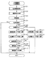
Next, normal processing will be described with reference to the flowchart of FIG.
通常処理において、ステップS701では、変動種別カウンタCSの更新を実行する。続くステップS702では、第1特定ランプ部43に表示される色の切り替えを行うための第1特定ランプ部制御処理を実行する。第1特定ランプ部制御処理では、大当たり判定や第1特定ランプ部43に配設されたLEDランプの光源スイッチのオンオフ制御などが行われる。また、第1特定ランプ部制御処理において、図柄表示装置41による第1図柄の変動表示の設定も行われる。
In the normal process, in step S701, the variation type counter CS is updated. In the subsequent step S702, a first specific lamp unit control process for switching the color displayed on the first
具体的には、大当たり乱数カウンタC1の値に基づいて大当たりか否かを判定し、さらに大当たり種別カウンタC2の値に基づいて大当たりの種類を決定する(いわゆる、確変大当たりか否かを決定する)。また、リーチ乱数カウンタC3の値及び変動種別カウンタCSの値に基づいて、第1特定ランプ部43に表示される色の切替表示時間、及び第1図柄の変動表示時間を決定する。なお、当該第1特定ランプ部制御処理にて第1特定ランプ部43のオンオフ制御が開始される毎に作動保留球数Nが1減算され、作動保留球数Nが0の場合にはオンオフ制御が開始されない。
Specifically, it is determined whether or not the jackpot is based on the value of the jackpot random number counter C1, and further determines the type of jackpot based on the value of the jackpot type counter C2 (determines whether or not it is a so-called probabilistic jackpot). . Further, based on the value of the reach random number counter C3 and the value of the variation type counter CS, the color switching display time displayed on the first
第1特定ランプ部制御処理の後は、ステップS703にて大入賞口開閉処理を実行する。大入賞口開閉処理では、大当たり状態である場合において可変入賞装置32の大入賞口を開放又は閉鎖する。すなわち、大当たり状態のラウンド毎に大入賞口を開放し、大入賞口の最大開放時間が経過したか、又は大入賞口に遊技球が規定数だけ入賞したかを判定する。この規定数だけ入賞したか否かの判定は、大入賞口用カウンタを確認することにより行われる。そして、これら何れかの条件が成立すると大入賞口を閉鎖する。
After the first specific lamp unit control process, a special winning opening opening / closing process is executed in step S703. In the big prize opening / closing process, the big prize opening of the variable
その後、ステップS704では、第2特定ランプ部44に表示される色の切り替え処理を行うための第2特定ランプ部制御処理を実行する。第2特定ランプ部制御処理では、ゲート保留球数が1以上であることを条件に第2特定ランプ部44における表示色の切り換えを開始する。この際、表示色の切り換え時間も設定する。また、既に取得されている第2特定ランプ乱数カウンタの値に基づいて停止表示する色を設定する。この停止表示される色として所定の色が設定された場合には、その色の停止表示後に、下作動口34に付随する電動役物34aが所定時間開放される。
Thereafter, in step S704, a second specific lamp unit control process for performing a process of switching the color displayed on the second
ステップS704の後は、ステップS705にて、遊技球発射制御処理を実行する。遊技球発射制御処理では、電源及び発射制御基板221の発射制御部221bから発射許可信号を入力していることを条件として、所定期間(例えば、0.6sec)に1回、遊技球発射機構53のソレノイドを励磁する。これにより、遊技球発射機構53の発射レール上にある遊技球が遊技領域に向けて打ち出される。当該処理についてより具体的には、主側MPU211は上記発射許可信号を入力していることを条件として、発射出力用ポートへの「0」出力と「1」出力とを所定周期で繰り返す。発射出力用ポートに「0」出力されている間は非発射信号が電源及び発射制御基板221に出力され、発射制御部221bではソレノイドを非励磁状態とする。一方、発射出力用ポートに「1」出力されている間は発射信号が電源及び発射制御基板221に出力され、発射制御部221bではソレノイドを励磁状態とする。
After step S704, a game ball launch control process is executed in step S705. In the game ball launch control process, the game
すなわち、主側MPU211は電源及び発射制御基板221に発射パルス信号を出力する。電源及び発射制御基板221の発射制御部221bは発射パルス信号の電圧を増幅させたソレノイド駆動信号(駆動電圧)をソレノイドに対して出力し、ソレノイドの出力軸を発射位置と収容位置とに移動させることで、遊技球の発射を制御する。
That is, the
ステップS705の後は、ステップS706にて入力状態監視処理を実行し、ステップS707にて払出用出力処理を実行する。これらの処理については、遊技球の払出制御に関係する処理であるため、後に説明する。 After step S705, an input state monitoring process is executed in step S706, and a payout output process is executed in step S707. Since these processes are processes related to payout control of game balls, they will be described later.
その後、ステップS708にて、主側RAM213に電断フラグが格納されているか否かを判定する。また、ステップS709では、主側RAM213に不正検知フラグが格納されているか否かを判定する。そして、これら電断フラグ及び不正検知フラグの格納状況に応じた処理を実行する。ちなみに、電断フラグが格納されているか否かの判定処理が、不正検知フラグが格納されているか否かの判定処理よりも先に実行されるため、両フラグが格納されている場合、電断フラグに応じた処理が優先されることとなる。
Thereafter, in step S708, it is determined whether or not the power interruption flag is stored in the
ここで、本パチンコ機10では、(1)電断フラグ及び不正検知フラグの両方が格納されていない場合、(2)電断フラグは格納されておらず不正検知フラグが格納されている場合、(3)電断フラグが格納されている場合、のそれぞれで異なる処理が実行される。そこで、以下にこれら各状況の処理を個別に説明する。
Here, in this
<電断フラグ及び不正検知フラグの両方が格納されていない場合>
先ず、電断フラグ及び不正検知フラグの両方が格納されていない場合について説明する。
<When both the power interruption flag and fraud detection flag are not stored>
First, a case where both the power interruption flag and the fraud detection flag are not stored will be described.
電断フラグ及び不正検知フラグの両方が格納されていない場合には、ステップS708及びステップS709の両方で否定判定をし、ステップS712に進む。ステップS712では、次の通常処理の実行タイミングに至ったか否か、すなわち前回の通常処理の開始からタイマ割込み処理が複数回数として予め設定された割込み基準回数(具体的には、2回)発生したか否かを判定する。このタイマ割込みの回数の把握として具体的には、主側RAM213に割込み回数カウンタエリアが設けられており、タイマ割込みが起動される度に当該カウンタエリアの値が1加算されるとともに、ステップS701の処理が実行される直前のタイミングで当該カウンタエリアの値が0クリアされる(初期化される)。タイマ割込み処理が割込み基準回数発生していない場合には、ステップS713に進む。
If both the power interruption flag and the fraud detection flag are not stored, a negative determination is made in both step S708 and step S709, and the process proceeds to step S712. In step S712, whether or not the next normal process execution timing has been reached, that is, the timer interrupt process has been set as a predetermined number of times (specifically, twice) from the start of the previous normal process has occurred. It is determined whether or not. Specifically, the main-
ステップS713では、乱数初期値カウンタCINIの更新を実行する。具体的には、乱数初期値カウンタCINIを1加算すると共に、そのカウンタ値が最大値に達した際0にクリアする(初期化する)。そして、乱数初期値カウンタCINIの更新値を、主側RAM213の該当するバッファ領域に格納する。また、ステップS714では、変動種別カウンタCSの更新を実行する。具体的には、変動種別カウンタCSを1加算すると共に、それらのカウンタ値が最大値に達した際それぞれ0にクリアする(初期化する)。そして、変動種別カウンタCSの更新値を、主側RAM213の該当するバッファ領域に格納する。
In step S713, the random number initial value counter CINI is updated. Specifically, the random number initial value counter CINI is incremented by 1 and cleared to 0 (initialized) when the counter value reaches the maximum value. Then, the update value of the random number initial value counter CINI is stored in the corresponding buffer area of the
その後、ステップS708に進む。そして、今回は、電断フラグ及び不正検知フラグの両方が格納されていない場合の処理であるため、ステップS708及びステップS709の両方で否定判定をし、ステップS712に進む。その後、前回の通常処理の開始からタイマ割込み処理が割込み基準回数発生するまで上述した処理を繰り返し、割込み基準回数に達した場合にはステップS701の処理に戻る。つまり、電断フラグ及び不正検知フラグの両方が格納されていない場合には、ステップS701〜ステップS707の処理が4msec周期で繰り返し実行されることとなる。なお、当該周期は、遊技の進行を良好に制御することができるのであれば、4msecに限定されない。 Thereafter, the process proceeds to step S708. And since this time is a process when both the power interruption flag and the fraud detection flag are not stored, a negative determination is made in both step S708 and step S709, and the process proceeds to step S712. Thereafter, the above-described processing is repeated from the start of the previous normal processing until the timer interrupt processing has occurred for the interrupt reference count, and when the interrupt reference count is reached, the processing returns to step S701. That is, when both the power interruption flag and the fraud detection flag are not stored, the processing from step S701 to step S707 is repeatedly executed at a cycle of 4 msec. Note that the period is not limited to 4 msec as long as the progress of the game can be well controlled.
<電断フラグは格納されておらず不正検知フラグが格納されている場合>
次に、電断フラグは格納されておらず不正検知フラグが格納されている場合について説明する。
<When power failure flag is not stored and fraud detection flag is stored>
Next, the case where the power failure flag is not stored and the fraud detection flag is stored will be described.
電断フラグは格納されておらず不正検知フラグが格納されている場合には、ステップS708にて否定判定をするとともにステップS709にて肯定判定をし、ステップS710に進む。ステップS710では、不正検知対応処理を実行する。 If the power interruption flag is not stored and the fraud detection flag is stored, a negative determination is made in step S708 and an affirmative determination is made in step S709, and the process proceeds to step S710. In step S710, fraud detection handling processing is executed.
不正検知対応処理では、発射出力用ポートに「0」出力する。これにより、既に説明したように非発射信号が電源及び発射制御基板221に出力され、発射制御部221bではソレノイドを非励磁状態とする。この場合、発射ハンドル54が操作されていたとしても、次回の遊技球発射制御処理(ステップS705)が実行されるまで、発射出力用ポートに「0」出力する状態が維持され、遊技球の発射が禁止される。
In the fraud detection handling process, “0” is output to the launch output port. As a result, the non-firing signal is output to the power source and the
また、不正検知対応処理では、ストローブ、ソレノイド、表示LED関係出力用ポートの全てに「0」出力する。ストローブ関係出力用ポートとは、払出制御基板222などの他の制御基板に対するストローブ信号の出力設定を行うためのポートであり、他の制御基板ではストローブ信号を入力することで主側MPU211から入力しているコマンドの確認処理を実行する。ストローブ関係出力用ポートに「0」出力されることにより、ストローブ信号の出力が停止されるとともに、次回のコマンド出力が実行されるまで、ストローブ関係出力用ポートに「0」出力する状態が維持され、ストローブ信号の出力が禁止される。
In the fraud detection handling process, “0” is output to all the strobe, solenoid, and display LED related output ports. The strobe-related output port is a port for setting the output of the strobe signal to another control board such as the
また、ソレノイド関係出力用ポートとは、可変入賞装置32の開閉状態設定を行うためのポートであり、「1」出力されている状況では可変入賞装置32が開放状態となり、「0」出力されている状況では可変入賞装置32が閉鎖状態となる。これにより、大当たり中において上記不正行為が行われた場合には、開放状態であった可変入賞装置32は閉鎖状態に切り換えられるとともに、次回の大入賞口開閉処理(ステップS703)が実行されるまで、ソレノイド関係出力用ポートに「0」出力する状態が維持され、可変入賞装置32の開放が禁止される。
The solenoid-related output port is a port for setting the open / close state of the variable winning
また、表示LED関係出力用ポートとは、第1特定ランプ部43及び第2特定ランプ部44の表示状態設定を行うためのポートであり、「0」出力されている状況では発光が停止された状態となる。これにより、上記不正行為が行われた場合には、第1特定ランプ部43及び第2特定ランプ部44における発光が停止されるとともに、次回の特定ランプ部制御処理(ステップS702又はステップS704)が実行されるまで、表示LED間系出力用ポートに「0」出力する状態が維持され、第1特定ランプ部43及び第2特定ランプ部44の発光が禁止される。
The display LED-related output port is a port for setting the display state of the first
ステップS710にて不正検知対応処理を実行した後は、ステップS711にて開放検知処理を実行する。ここで、開放検知処理について、図18のフローチャートを参照して説明する。なお、当該開放検知処理は、前扉枠14及び内枠13が開放状態であるか否かの監視を不正検知フラグが格納されている状態において行うためのものであり、不正検知フラグが格納されていない状態における前面扉14及び内枠13が開放状態であるか否かの監視は入力状態監視処理(ステップS706)において別に行われる。
After executing the fraud detection handling process in step S710, the opening detection process is executed in step S711. Here, the opening detection process will be described with reference to the flowchart of FIG. The opening detection process is for monitoring whether or not the
さて、開放検知処理では、ステップS801〜ステップS805にて前扉枠14についての開放検知処理を実行するとともに、ステップS806〜ステップS810にて内枠13についての開放検知処理を実行する。
In the opening detection process, the opening detection process for the
前扉枠14に関する開放検知処理では、先ずステップS801にて主側RAM213に設けられた前扉枠開放フラグ格納エリアに前扉枠開放フラグが格納されているか否かを判定する。前扉枠開放フラグが格納されていない場合には、ステップS802にて前扉枠開放スイッチ22から開放検知信号を入力しているか否かを判定する。
In the opening detection process related to the
開放検知信号を入力していない場合には、そのまま内枠13についての開放検知処理に移行する。開放検知信号を入力している場合には、ステップS803に進む。ステップS803では、主側RAM213に前扉枠開放フラグを格納する。また、前扉枠開放コマンドを音声ランプ制御基板224のMPU241に出力する。音声ランプ制御基板224のMPU241では、当該前扉枠開放コマンドを入力することで、予め定められた前扉枠開放報知を実行するように各種報知部を駆動制御する。この前扉枠開放報知として具体的には、スピーカ部64からの音の出力、エラー表示ランプ部63の点灯又は図柄表示装置41の表示画面に報知用の文字若しくは図形を表示するといった表示画面による報知の少なくとも一つが行われる。また、ホール側への出力処理を実行する。具体的には、外部端子板133を通じて前扉枠開放信号が遊技ホール側の管理装置に出力されるように、外部端子出力用ポートに前扉枠開放情報を出力する。これにより、遊技ホール側の管理装置において前扉枠14が開放状態であることを把握することができる。その後、内枠13に関する開放検知処理に移行する。
When the opening detection signal is not input, the process proceeds to the opening detection process for the
一方、ステップS801にて前扉枠開放フラグが格納されていると判定した場合には、ステップS804にて前扉枠開放スイッチ22から開放検知信号を入力しているか否かを判定する。
On the other hand, if it is determined in step S801 that the front door frame opening flag is stored, it is determined in step S804 whether an opening detection signal is input from the front door
開放検知信号を入力している場合には、そのまま内枠13についての開放検知処理に移行する。開放検知信号を入力していない場合には、ステップS805に進む。ステップS805では、主側RAM213から前扉枠開放フラグを消去する。また、前扉枠閉鎖コマンドを音声ランプ制御基板224のMPU241に出力する。音声ランプ制御基板224のMPU241では、当該前扉枠閉鎖コマンドを入力することで、上記前扉枠開放報知を終了させる。また、ホール側への出力処理を実行する。具体的には、遊技ホール側の管理装置への前扉枠開放信号の出力が停止されるように、外部端子出力用ポートに前扉枠開放情報を出力している状態を停止する。これにより、遊技ホール側の管理装置において前扉枠14が閉鎖状態となったことを把握することができる。その後、内枠13についての開放検知処理に移行する。
When the opening detection signal is input, the process proceeds to the opening detection process for the
内枠13についての開放検知処理では、先ずステップS806にて主側RAM213に設けられた内枠開放フラグ格納エリアに内枠開放フラグが格納されているか否かを判定する。内枠開放フラグが格納されていない場合には、ステップS807にて内枠開放スイッチ134から開放検知信号を入力しているか否かを判定する。
In the release detection process for the
開放検知信号を入力していない場合には、そのまま本開放検知処理を終了する。開放検知信号を入力している場合には、ステップS808に進む。ステップS808では、主側RAM213に内枠開放フラグを格納する。また、内枠開放コマンドを音声ランプ制御基板224のMPU241に出力する。音声ランプ制御基板224のMPU241では、当該内枠開放コマンドを入力することで、予め定められた内枠開放報知を実行するように各種報知部を駆動制御する。この内枠開放報知として具体的には、スピーカ部64からの音の出力、エラー表示ランプ部63の点灯又は図柄表示装置41の表示画面に報知用の文字若しくは図形を表示するといった表示画面による報知の少なくとも一つが行われる。なお、この内枠開放報知の態様は上述した前扉枠開放報知と識別可能なものであるが、当該前扉枠開放報知と同一の態様としてもよい。また、ホール側への出力処理を実行する。具体的には、外部端子板133を通じて内枠開放信号が遊技ホール側の管理装置に出力されるように、外部端子出力用ポートに内枠開放情報を出力する。これにより、遊技ホール側の管理装置において内枠13が開放状態であることを把握することができる。その後、本開放検知処理を終了する。
If the opening detection signal is not input, the opening detection process is terminated as it is. If an open detection signal is input, the process proceeds to step S808. In step S808, the inner frame release flag is stored in the
一方、ステップS806にて内枠開放フラグが格納されていると判定した場合には、ステップS809にて内枠開放スイッチ134から開放検知信号を入力しているか否かを判定する。
On the other hand, if it is determined in step S806 that the inner frame opening flag is stored, it is determined in step S809 whether an opening detection signal is input from the inner
開放検知信号を入力している場合には、そのまま本開放検知処理を終了する。開放検知信号を入力していない場合には、ステップS810に進む。ステップS810では、主側RAM213から内枠開放フラグを消去する。また、内枠閉鎖コマンドを音声ランプ制御基板224のMPU241に出力する。音声ランプ制御基板224のMPU241では、当該内枠閉鎖コマンドを入力することで、上記内枠開放報知を終了させる。また、ホール側への出力処理を実行する。具体的には、遊技ホール側の管理装置への内枠開放信号の出力が停止されるように、外部端子出力用ポートに内枠開放情報を出力している状態を停止する。これにより、遊技ホール側の管理装置において内枠13が閉鎖状態となったことを把握することができる。その後、本開放検知処理を終了する。
If the opening detection signal is input, the opening detection process is terminated as it is. If no opening detection signal is input, the process proceeds to step S810. In step S810, the inner frame release flag is erased from the
通常処理(図17)の説明に戻り、ステップS711にて開放検知処理を実行した後は、ステップS712の処理を実行することなく、ステップS713に進む。これにより、主側RAM213に不正検知フラグが格納されたタイミングにおいて既にタイマ割込み処理が2回実行されていたとしても、ステップS712の処理が実行されないためステップS701の処理に復帰することがない。これにより、遊技を進行させる進行用処理の一部の処理であるステップS701〜ステップS707の処理が実行されなくなり、遊技が進行しないように規制されることとなる。
Returning to the description of the normal process (FIG. 17), after the opening detection process is executed in step S711, the process proceeds to step S713 without executing the process of step S712. As a result, even if the timer interrupt process has already been executed twice at the timing when the fraud detection flag is stored in the
なお、既に説明したように、不正検知フラグが格納されている場合には、タイマ割込み処理(図11)のステップS103の不正監視処理及びステップS107の始動入賞処理も実行されなくなり、この点からも遊技が進行しないように規制されることとなる。 As described above, when the fraud detection flag is stored, the fraud monitoring process in step S103 and the start winning process in step S107 of the timer interrupt process (FIG. 11) are not executed. The game will be regulated so that it will not progress.
その後、ステップS713及びステップS714の処理を実行した後に、ステップS708に戻る。そして、ステップS710〜ステップS711及びステップS713〜ステップS714の各処理が繰り返されることとなる。 Then, after executing the processes of step S713 and step S714, the process returns to step S708. And each process of step S710-step S711 and step S713-step S714 will be repeated.
ここで、ステップS711の処理が実行されることにより、上記のように不正検知フラグが格納され遊技が進行しないように規制されている状態であっても、内枠13の開放操作及び前扉枠14の開放操作の両方を監視することができる。例えば、不正検知フラグが格納されている状態において内枠13の開放操作及び前扉枠14の開放操作の監視が行われない構成を想定すると、パチンコ機10に振動を与えた後に内枠13の開放操作や前扉枠14の開放操作が行われたとしても、それを主側MPU211において特定することができない。そうすると、当該状況において主制御装置91への不正行為や遊技盤24への不正行為が行われてしまうことが懸念される。これに対して、本構成によれば、このような不都合の発生を阻止することができる。つまり、不正特定状態が設定されている状況において、さらなる二次的な不正行為の発生を阻止することができる。
Here, even if the process of step S711 is executed and the fraud detection flag is stored and the game is restricted from proceeding as described above, the opening operation of the
<電断フラグが格納されている場合>
次に、電断フラグが格納されている場合について説明する。
<When power interruption flag is stored>
Next, a case where the power interruption flag is stored will be described.
電断フラグが格納されている場合には、不正検知フラグが格納されているか否かに関係なく、ステップS715以降の電断時処理を実行する。つまり、ステップS715では、タイマ割込み処理の発生を禁止し、その後、ステップS716にてRAM判定値を算出、保存し、ステップS717にて主側RAM213のアクセスを禁止した後に、電源が完全に遮断して処理が実行できなくなるまで無限ループを継続する。
When the power interruption flag is stored, the power interruption process after step S715 is executed regardless of whether the fraud detection flag is stored. That is, in step S715, the generation of the timer interrupt process is prohibited, and then the RAM determination value is calculated and stored in step S716. After the access to the
ここで、既に説明したように、タイマ割込み処理(図11)にて実行される電断信号監視処理(図12)において電断の発生を特定したとしても即座に電断時処理を実行するのではなく、主側RAM213に電断フラグを格納するようにし、さらに電断フラグが格納されているか否かの判定を通常処理においてステップS701〜ステップS707の処理を実行した後に行うことにより、復電後に通常処理が実行される場合、常に最初の処理から実行されることとなる。これにより、電断発生時に実行していた処理の番地をスタック情報として主側RAM213に記憶しなくても、電断前の状態に復帰することが可能となる。
Here, as already described, even if the occurrence of power interruption is specified in the power interruption signal monitoring process (FIG. 12) executed in the timer interruption process (FIG. 11), the power interruption process is immediately executed. Instead, the power failure flag is stored in the
また、不正検知フラグが格納されている状況であっても、電断信号監視処理の実行及びステップS708の電断フラグの判定処理を依然として実行するようにしたことにより、不正検知フラグが格納されている状況で電断が発生した場合であっても電断時処理を実行することができる。 Even if the fraud detection flag is stored, the execution of the power interruption signal monitoring process and the determination process of the power interruption flag in step S708 are still executed, so that the fraud detection flag is stored. Even when a power interruption occurs in a situation, the power interruption process can be executed.
また、通常処理におけるステップS708〜ステップS714の範囲内において不正検知対応処理を実行したことで、電断フラグが格納されているか否かを判定するための電断判定用処理を複数独立して設定する必要がなくなる。例えば、不正監視処理(図13)において、遊技が進行しないように規制するための不正検知対応処理を実行する構成を想定すると、当該不正監視処理における一部の処理として電断フラグが格納されているか否かの判定処理を行う必要が生じる。そうすると、通常処理において電断フラグが格納されているか否かの判定処理を行うとともに、不正監視処理において電断フラグが格納されているか否かの判定処理を行う必要が生じる。これに対して、本パチンコ機10では上記のとおり、通常処理において電断フラグが格納されているか否かの判定処理を行うだけでよく、主側MPU211の処理負荷が低減される。
In addition, by executing the fraud detection handling process within the range of step S708 to step S714 in the normal process, a plurality of power interruption determination processes for determining whether the power interruption flag is stored are set independently. There is no need to do it. For example, in a fraud monitoring process (FIG. 13), assuming a configuration in which a fraud detection corresponding process for restricting a game from progressing is assumed, a power interruption flag is stored as a part of the fraud monitoring process. It is necessary to determine whether or not there is. Then, it is necessary to perform a determination process whether or not the power interruption flag is stored in the normal process and to perform a determination process whether or not the power interruption flag is stored in the fraud monitoring process. On the other hand, in the
<遊技球の払出に関する電気的構成>
次に、遊技球の払出に関する電気的構成及び処理構成について詳細に説明する。先ず、電気的構成について、図19のブロック図を参照しながら説明する。図19では、電力の供給ラインを二重線矢印で示し、信号ラインを実線矢印で示す。
<Electric configuration for paying out game balls>
Next, the electrical configuration and processing configuration related to game ball payout will be described in detail. First, the electrical configuration will be described with reference to the block diagram of FIG. In FIG. 19, a power supply line is indicated by a double line arrow, and a signal line is indicated by a solid line arrow.
主制御基板201と払出制御基板222とはハーネスなどの電気配線(信号線)を介して電気的に接続されており、主制御基板201から払出制御基板222に指令情報としてのコマンドが出力されるとともに、払出制御基板222から主制御基板201には各種の電気信号が出力される。
The
主側MPU211の入力ポート211aには払出制御基板222から賞球許可信号を含めた各種の電気信号が入力されるとともに各種センサ等からの電気信号が入力される。なお、賞球許可信号の詳細については後に説明する。また、既に説明したように、主側MPU211の入力ポート211aには、前扉枠開放スイッチ22及び内枠開放スイッチ134からの電気信号などが入力される。
Various electric signals including a prize ball permission signal are input from the
なお、前扉枠開放スイッチ22及び内枠開放スイッチ134から出力された電気信号は、電源及び発射制御基板221と払出制御基板222とに中継された後に主制御基板201に入力される。この場合、払出制御基板222においては、これら前扉枠開放スイッチ22及び内枠開放スイッチ134からの電気信号を中継するだけであり、払出側MPU231には入力されない。これは電源及び発射制御基板221についても同様である。
The electrical signals output from the front door
遊技球の払出に関する主側RAM213の構成について説明する。
A configuration of the
主側RAM213には賞球用カウンタエリア251が設けられている。賞球用カウンタエリア251には、15個賞球用カウンタエリアと、10個賞球用カウンタエリアと、4個賞球用カウンタエリアと、3個賞球用カウンタエリアとが設けられている。
The
ここで、本パチンコ機10には既に説明したように、賞球用入球部(又は賞払出用通過部)として、一般入賞口31、可変入賞装置32、上作動口33及び下作動口34が設けられており、各賞球用入球部ごとに入球に対する賞球個数(払い出される遊技球の個数)が異なっている。具体的には、一般入賞口31に入球した場合の賞球個数は10個であり、可変入賞装置32に入球した場合の賞球個数は15個であり、上作動口33に入球した場合の賞球個数は3個であり、下作動口34に入球した場合の賞球個数は4個である。
Here, as already described in this
当該構成において、15個賞球用カウンタエリアは可変入賞装置32への入球に対する15個賞球をあと何回行うかを記憶するものであり、10個賞球用カウンタエリアは一般入賞口31への入球に対する10個賞球をあと何回行うかを記憶するものであり、4個賞球用カウンタエリアは下作動口34への入球に対する4個賞球をあと何回行うかを記憶するものであり、3個賞球用カウンタエリアは上作動口33への入球に対する3個賞球をあと何回行うかを記憶するものである。各賞球用カウンタエリアは、それぞれ1バイトで構成されており、賞球の未実施回数を最大で255回まで覚えることができる。
In this configuration, the 15 winning ball counter area stores how
なお、上記賞球個数パターンは一例であり、各個数は任意である。また、賞球数のパターンも上記の4種類に限定されることはなく、2種類、3種類又は5種類以上であってもよい。また、各賞球用カウンタエリアは1バイトに限定されることはなく、2バイト又は3バイト以上であってもよい。さらには各賞球用カウンタエリアに記憶可能な賞球の未実施回数は、最大で255回であることは必須ではなく、複数回が記憶可能であれば、255回よりも少なく又は多くてもよい。 The prize ball number pattern is an example, and each number is arbitrary. Also, the pattern of the number of winning balls is not limited to the above four types, and may be two types, three types, or five types or more. Each prize ball counter area is not limited to 1 byte, and may be 2 bytes or 3 bytes or more. Furthermore, it is not essential that the number of unexecuted prize balls that can be stored in each prize ball counter area is 255 at the maximum, and if multiple times can be stored, it may be less or more than 255 times. Good.
主側MPU211では、賞球用カウンタエリア251に記憶されている情報(賞情報)に基づいて、入賞発生の有無を判定し、入賞発生有りと判定した場合にはその入賞の種類に対応した賞球コマンドを払出制御基板222に出力する。なお、賞球コマンドは、主制御基板201のROM212のコマンド記憶エリア212aに予め記憶されている。
The
賞球コマンドとしては、15個賞球コマンドと、10個賞球コマンドと、4個賞球コマンドと、3個賞球コマンドとが設定されている。15個賞球用カウンタエリアに記憶されている賞球情報に基づいて賞球コマンドが出力される場合には15個賞球コマンドが出力され、10個賞球用カウンタエリアに記憶されている賞球情報に基づいて賞球コマンドが出力される場合には10個賞球コマンドが出力され、4個賞球用カウンタエリアに記憶されている賞球情報に基づいて賞球コマンドが出力される場合には4個賞球コマンドが出力され、3個賞球用カウンタエリアに記憶されている賞球情報に基づいて賞球コマンドが出力される場合には3個賞球コマンドが出力される。 As prize ball commands, 15 prize ball commands, 10 prize ball commands, 4 prize ball commands, and 3 prize ball commands are set. When a prize ball command is output based on the prize ball information stored in the 15 prize ball counter area, 15 prize ball commands are output and the prizes stored in the 10 prize ball counter area are output. When a prize ball command is output based on the ball information, ten prize ball commands are output, and a prize ball command is output based on the prize ball information stored in the counter area for four prize balls The four prize ball commands are outputted, and when the prize ball command is outputted based on the prize ball information stored in the three prize ball counter area, the three prize ball commands are outputted.
各賞球コマンドは2バイトで構成されている。すなわち、各賞球コマンドは上位情報と下位情報とを備えており、それら各情報はそれぞれ1バイトで構成されている。これら上位情報及び下位情報のうち、上位情報には払側MPU231において本コマンドが賞球コマンドであることを特定するための情報が設定されており、下位情報には払出側MPU231において賞球数を特定するための情報が設定されている。
Each prize ball command is composed of 2 bytes. That is, each prize ball command includes high-order information and low-order information, and each piece of information is composed of 1 byte. Among the upper information and lower information, information for specifying that the command is a prize ball command is set in the higher information in the
その他、主側RAM213には、前扉枠カウンタエリア252、賞球許可カウンタエリア253及び各種フラグ格納エリア254が設けられている。前扉枠カウンタエリア252は、主側MPU211において前扉枠14の開閉の有無を判定する場合に用いられる。また、賞球許可カウンタエリア253は、主側MPU211において賞球許可信号に関する処理を実行する上で用いられる。また、各種フラグ格納エリア254は、主側MPU211において各種の制御処理を実行する上で用いられる。
In addition, the
払出制御基板222は払出装置114と電気的に接続されており、払出側MPU231は、払出モータ125に駆動信号を出力するとともに、払出球検知センサ126から遊技球の検知の有無を示す電気信号を入力する。また、払出制御基板222は球貸用接続端子板143を介して球貸装置Yと電気的に接続されており、払出側MPU231は、球貸装置Yとの間で電気信号の入出力を行うことで貸球の制御を実行する。
The
また、払出側MPU231は、満タン検知センサ88及び球無検知センサ115から電気信号を入力し、下皿82が満タン状態となっているか否かの特定や、タンク111が球無状態となっているか否かの特定を行う。これら満タン検知センサ88及び球無検知センサ115のうち満タン検知センサ88から出力された電気信号は、電源及び発射制御基板221に中継された後に払出制御基板222に入力される。なお、払出側MPU231は、下皿82が満タン状態となっているか否かの特定結果を主側MPU211に出力する。これにより、下皿82が満タン状態となっているか否かを主側MPU211において把握することができるようになっている。
Further, the
払出側RAM233の構成について説明する。
The configuration of the
払出側RAM233には満タンカウンタエリア261が設けられている。満タンカウンタエリア261は、払出側MPU231において下皿82が満タン状態であるか否かを特定する上で用いられる。また、払出側RAM233には球無カウンタエリア262が設けられている。球無カウンタエリア262は、払出側MPU231においてタンク111が球無状態であるか否かを特定する上で用いられる。また、払出側RAM233にはコマンド格納エリア263が設けられている。コマンド格納エリア263は、主側MPU211から入力した賞球コマンドを一時的に格納しておく上で用いられる。
The
また、払出側RAM233には賞球数記憶エリア264が設けられている。賞球数記憶エリア264は、複数のビット(8ビット)が列状に並べられてなる1バイトで構成されており、各ビットには「0」(データ0又は無情報)又は「1」(データ1又は有情報)が設定される。そして、賞球数記憶エリア264は、払出側MPU231において賞球コマンドを解析することで特定した賞球数の情報を記憶しておくための機能を有している。この場合、賞球数の情報(賞球数情報又は賞払出数情報)は、所定の遊技媒体数の範囲内において各ビットのデータ1の設定パターンと遊技媒体数とが1対1で対応した情報である。具体的には、下位のビットから上位のビットに向けて予め定められた順序で各ビットに「1」(データ1又は有情報)が設定され、上位側のビットに「1」が設定されているほど対応する賞球数が大きい数となるように2進数で表される情報である。なお、賞球コマンドから賞球数の情報を特定する場合には、払出制御基板222のROM232に設けられた賞球テーブル記憶エリア232aが参照される。
The
また、払出側RAM233には貸球数記憶エリア265が設けられている。貸球数記憶エリア265は、1バイトで構成されており、払出側MPU231において球貸装置Yから入力した貸球数の情報を記憶しておくための機能を有している。また、払出側RAM233には払出個数カウンタエリア266が設けられている。払出個数カウンタエリア266は、1バイトで構成されており、払出側MPU231において遊技球の払出を実行する上での実行エリアとしての機能を有する。
In addition, the
なお、賞球数記憶エリア264、貸球数記憶エリア265及び払出個数カウンタエリア266は、1バイトに限定されることはなく、2バイト又は3バイト以上であってもよい。また、これら各エリア264〜266が同一のバイト数である必要はない。
The award ball
その他、払出側RAM233には各種フラグ格納エリア267が設けられている。各種フラグ格納エリア267は、払出側MPU231において各種の制御処理を実行する上で用いられる。
In addition, the
なお、払出側RAM233には、上記各エリア261〜267の他に、主側MPU211からコマンドを入力した場合にそのコマンドを一時的に格納しておくためのリングバッファが設けられている。リングバッファは複数の記憶領域を備えているとともに、書込みポインタと読み出しポインタとが設定されている。書込みポインタに基づき各記憶領域にコマンドが順次書き込まれていくとともに、読み出しポインタに基づき各記憶領域に記憶されたコマンドが順次読み出されていく。
The
電源及び発射制御基板221の電入時用電源部221aからの電力は、主側MPU211のVCC端子、及び払出側MPU231のVCC端子に供給される。VCC端子に供給された電力により、外部電源からの電力供給が行われている状況において、各MPU211,331にて各種制御処理が実行されるとともに、各RAM213,333にて情報の記憶保持が行われる。
The power from the power-on
また、電源及び発射制御基板221の電断時用電源部221cからの電力は、主側MPU211のVBB端子に供給される。つまり、電断時用電源部221cからの電力は、主側RAM213に供給されるが、払出側RAM233には供給されない。VBB端子に供給された電力により、外部電源からの電力供給が遮断されている状況において、主側RAM213にて情報の記憶保持が行われる。なお、既に説明したように、電入時用電源部221a及び電断時用電源部221cから主側MPU211に供給される電力は、電断監視基板203にて中継される。また、払出側MPU231のVBB端子(図示略)は、アースされている又はいずれの電気配線とも接続されていない。
In addition, power from the power supply and
<遊技球の払出に関する処理構成であって主側MPU211における処理構成>
次に、主側MPU211における遊技球の払出に関する処理構成について説明する。以下の説明において、カウンタエリアの値とは、バイト単位で構成されたカウンタエリアの値を仮想的に10進数で表現した値のことをいう。
<Processing configuration related to game ball payout and processing configuration in
Next, a processing configuration related to paying out game balls in the
<入力状態監視処理>
先ず、通常処理(図17)のステップS706にて実行される入力状態監視処理について、図20のフローチャートを参照しながら説明する。
<Input status monitoring process>
First, the input state monitoring process executed in step S706 of the normal process (FIG. 17) will be described with reference to the flowchart of FIG.
入力状態監視処理では、先ずステップS901にて、入力ポート211aから入力情報を取得する。具体的には、主側MPU211に設けられた1バイト単位の汎用レジスタに、入力ポート211aの入力情報を格納する。
In the input state monitoring process, first, in step S901, input information is acquired from the
続くステップS902では、遊技球の払出に関して異常が発生しているか否かを特定するための払出異常信号監視処理を実行する。詳細には、払出異常信号監視処理では、払出制御基板222から異常信号を入力している旨の情報が汎用レジスタに格納されている場合に、払出異常の発生を主側MPU211において特定する。そして、払出異常の発生を特定した場合には、音声ランプ制御基板224に払出異常コマンド(払出異常情報)を出力し、異常報知を実行させる。
In a succeeding step S902, a payout abnormality signal monitoring process for specifying whether or not an abnormality has occurred regarding the payout of the game ball is executed. Specifically, in the payout abnormality signal monitoring process, when information indicating that an abnormal signal is input from the
続くステップS903では、下皿82が満タン状態となっているか否かを特定するための満タン信号監視処理を実行する。詳細には、満タン信号監視処理では、払出制御基板222から満タン信号を入力している旨の情報が汎用レジスタに格納されている場合に、下皿82が満タン状態であることを主側MPU211において特定する。そして、下皿82が満タン状態であることを特定した場合には、音声ランプ制御基板224に満タン状態コマンド(満タン状態情報)を出力し、満タン報知を実行させる。
In the subsequent step S903, a full tank signal monitoring process for specifying whether or not the
続くステップS904では、内枠13が開放状態となっているか否かを特定するための内枠開放信号監視処理を実行する。詳細には、内枠開放信号監視処理では、内枠開放スイッチ134から内枠開放信号を入力している旨の情報が汎用レジスタに格納されている場合に、内枠13が開放状態であることを主側MPU211において特定する。そして、内枠13が開放状態であることを特定した場合には、音声ランプ制御基板224に内枠開放状態コマンド(本体開放報知用情報)を出力し、本体開放報知を実行させる。
In a succeeding step S904, an inner frame open signal monitoring process for specifying whether or not the
その後、ステップS905にて前扉枠開放信号監視処理を実行するとともに、ステップS906にて賞球許可信号監視処理を実行した後に、本入力状態監視処理を終了する。 Thereafter, the front door frame opening signal monitoring process is executed in step S905, and after the prize ball permission signal monitoring process is executed in step S906, the input state monitoring process is terminated.
<前扉枠開放信号監視処理>
次に、上記ステップS905の前扉枠開放信号監視処理について、図21のフローチャートを参照しながら説明する。
<Front door frame opening signal monitoring processing>
Next, the front door frame opening signal monitoring process in step S905 will be described with reference to the flowchart of FIG.
ここで、前扉枠開放信号監視処理は、(1)前扉枠14が閉鎖状態であることが特定された後であって当該閉鎖状態が継続されている場合の処理、(2)前扉枠14が閉鎖状態から開放状態となった場合であって開放状態であることが特定されるまでの処理、(3)前扉枠14が開放状態であることが特定された後であって当該開放状態が継続されている場合の処理、(4)前扉枠14が開放状態から閉鎖状態となった場合であって閉鎖状態であることが特定されるまでの処理、に大別される。そこで、これら状況の処理を個別に説明する。
Here, the front door frame opening signal monitoring process is (1) a process when the closed state is continued after the
先ず、上記(1)の前扉枠14が閉鎖状態であることが特定された後であって当該閉鎖状態が継続されている場合の処理について説明する。
First, the processing when the
先ずステップS1001では、前扉枠14が開放状態であることを示す前扉枠開放信号を入力している旨の前扉枠開放情報が汎用レジスタに格納されているか否かを判定する。今回は前扉枠14が閉鎖状態である場合であるため、ステップS1001にて否定判定をし、ステップS1002に進む。
First, in step S1001, it is determined whether or not the front door frame opening information indicating that the front door frame opening signal indicating that the
ステップS1002では、主側RAM213の前扉枠カウンタエリア252における第1前扉枠カウンタエリア(開放特定契機把握用手段)に、開放特定基準回数を格納する。具体的には、前扉枠カウンタエリア252に「3」を格納する。第1前扉枠カウンタエリアは、閉鎖状態の前扉枠14が開放状態となった場合に、主側MPU211において前扉枠14が開放状態となったことを特定する場合に用いられるカウンタである。
In step S <b> 1002, the opening specific reference number is stored in the first front door frame counter area (opening specific trigger grasping means) in the front door
続くステップS1003では、主側RAM213の前扉枠カウンタエリア252における第2前扉枠カウンタエリア(閉鎖特定契機把握用手段)が「0」となっているか否かを判定する。第2前扉枠カウンタエリアは、開放状態の前扉枠14が閉鎖状態となった場合に、主側MPU211において前扉枠14が閉鎖状態となったことを特定する場合に用いられるカウンタである。当該第2前扉枠カウンタエリアは、前扉枠14が閉鎖状態となったことを特定した後は、「0」の状態で維持される。したがって、前扉枠14が閉鎖状態であることが特定された後であって当該閉鎖状態が継続されている場合には、第2前扉枠カウンタエリアは「0」であり、ステップS1003にて肯定判定をし、そのまま本前扉枠開放信号監視処理を終了する。
In subsequent step S1003, it is determined whether or not the second front door frame counter area (the closing specific trigger grasping means) in the front door
次に、上記(2)の前扉枠14が閉鎖状態から開放状態となった場合であって開放状態であることが特定されるまでの処理について説明する。
Next, a process until the
今回は前扉枠14が開放状態である場合であるため、ステップS1001にて肯定判定をし、ステップS1001に進む。ステップS1001では、主側RAM213の第2前扉枠カウンタエリアに、閉鎖特定基準値情報を格納する。具体的には、第2前扉枠カウンタエリアに「250」を格納する。
Since this time is the case where the
続くステップS1012では、第1前扉枠カウンタエリアが「0」となっているか否かを判定する。今回は、前扉枠14が閉鎖状態から開放状態となった場合であって開放状態であることが特定されるまでの処理であるため、前扉枠14が閉鎖状態の場合にステップS1002にて第1前扉枠カウンタエリアに格納された開放特定基準値情報が未だ「0」となっていない状態である。したがって、ステップS1012にて否定判定をし、ステップS1013に進む。
In a succeeding step S1012, it is determined whether or not the first front door frame counter area is “0”. This time, since the process is a process until the
ステップS1013では、第1前扉枠カウンタエリアの値を1減算する。続くステップS1014では、第1前扉枠カウンタエリアの値が「0」か否かを判定する。つまり、前扉枠14が閉鎖状態から開放状態となった場合であって開放状態であることが特定されるまでは、前扉枠開放信号監視処理が実行される度に第1前扉枠カウンタエリアの値が1減算される。また、前扉枠開放信号監視処理は、通常処理の一部の処理として実行されるため、その実行周期は約4msecである。また、前扉枠14が閉鎖状態の場合には、ステップS1002にて第1前扉枠カウンタエリアに「3」が格納される。したがって、ステップS1014では、前扉枠14が開放操作され閉鎖状態から開放状態となった時点(前扉枠開放スイッチ22から前扉枠開放信号が出力された時点)から12msecが経過したか否かを判定していることとなる。
In step S1013, 1 is subtracted from the value of the first front door frame counter area. In a succeeding step S1014, it is determined whether or not the value of the first front door frame counter area is “0”. In other words, until the front door frame opening signal monitoring process is executed until the
第1前扉枠カウンタエリアの値が「0」でない場合には、ステップS1014にて否定判定をし、そのまま本前扉枠開放信号監視処理を終了する。第1前扉枠カウンタエリアの値が「0」である場合には、ステップS1014にて肯定判定をし、ステップS1015に進む。ステップS1015では、主側RAM213の前扉枠開放フラグ格納エリアに前扉枠開放フラグが格納されているか否かを判定する。前扉枠開放フラグが格納されている場合には、そのまま本前扉枠開放信号監視処理を終了する。前扉枠開放フラグが格納されていない場合には、ステップS1016に進む。
If the value of the first front door frame counter area is not “0”, a negative determination is made in step S1014, and the front door frame opening signal monitoring process is terminated as it is. When the value of the first front door frame counter area is “0”, an affirmative determination is made in step S1014, and the process proceeds to step S1015. In step S1015, it is determined whether or not the front door frame opening flag is stored in the front door frame opening flag storage area of the
ステップS1016では、前扉枠開放フラグ格納エリア(前面体開放情報記憶手段)に前扉枠開放フラグ(前面体開放情報)を格納する。これにより、主側MPU211において前扉枠14が開放状態であることが特定される。続くステップS1017では、主側RAM213の前扉枠状態変化フラグ格納エリアに前扉枠状態変化フラグを格納する。これにより、主側MPU211において前扉枠14が開放状態であることを特定したタイミングであることが特定される。続くステップS1018では、前扉枠開放コマンドをセットする。当該前扉枠開放コマンドは、後述する払出用出力処理にて払出制御基板222に出力され、払出側MPU231では前扉枠開放コマンドを入力することで、前扉枠14が開放状態であることを特定する。
In step S1016, the front door frame release flag (front body release information) is stored in the front door frame release flag storage area (front body release information storage means). Thereby, it is specified in the
その後、ステップS1010ではサブコマンド設定処理を実行する。サブコマンド設定処理では、音声ランプ制御基板224に前扉枠開放状態コマンド(前面体開放報知用情報)を出力し、前面体開放報知を実行させる。
Thereafter, in step S1010, a subcommand setting process is executed. In the sub-command setting process, a front door frame opening state command (front body opening notification information) is output to the sound
次に、上記(3)の前扉枠14が開放状態であることが特定された後であって当該開放状態が継続されている場合の処理について説明する。
Next, a process when the
今回は前扉枠14が開放状態である場合であるため、ステップS1001にて肯定判定をし、ステップS1011に進み、主側RAM213の第2前扉枠カウンタエリアに「250」を格納する。続くステップS1012では、第1前扉枠カウンタエリアが「0」となっているか否かを判定する。今回は前扉枠14が開放状態であることが特定された後であって当該開放状態が継続されている場合であるため、第1前扉枠カウンタエリアが「0」の状態が維持されている。したがって、ステップS1012にて肯定判定をし、そのまま本前扉枠開放信号監視処理を終了する。
Since this time is the case where the
次に、上記(4)の前扉枠14が開放状態から閉鎖状態となった場合であって閉鎖状態であることが特定されるまでの処理について説明する。
Next, a process until the
今回は前扉枠14が閉鎖状態である場合であるため、ステップS1001にて否定判定をし、ステップS1002に進み、主側RAM213の第1前扉枠カウンタエリアに「3」を格納する。
Since this time is the case where the
続くステップS1003では、主側RAM213の第2前扉枠カウンタエリアが「0」となっているか否かを判定する。今回は、前扉枠14が開放状態から閉鎖状態となった場合であって閉鎖状態が特定されるまでの処理であるため、前扉枠14が開放状態の場合にステップS1011にて第2前扉枠カウンタエリアに格納された閉鎖特定基準回数が未だ「0」となっていない状態である。したがって、ステップS1003にて否定判定をし、ステップS1004に進む。
In a succeeding step S1003, it is determined whether or not the second front door frame counter area of the
ステップS1004では、第2前扉枠カウンタエリアの値を1減算する。続くステップS1005では、第2前扉枠カウンタエリアの値が「0」か否かを判定する。つまり、前扉枠14が開放状態から閉鎖状態となった場合であって閉鎖状態であることが特定されるまでは、前扉枠開放信号監視処理が実行される度に第2前扉枠カウンタエリアの値が1減算される。また、前扉枠開放信号監視処理は、通常処理の一部の処理として実行されるため、その実行周期は約4msecである。また、前扉枠14が開放状態の場合には、ステップS1011にて第2前扉枠カウンタエリアに「250」が格納される。したがって、ステップS1005では、前扉枠14が閉鎖操作され開放状態から閉鎖状態となった時点(前扉枠開放スイッチ22からの前扉枠開放信号の出力が停止された時点)から1secが経過したか否かを判定していることとなる。
In step S1004, 1 is subtracted from the value of the second front door frame counter area. In a succeeding step S1005, it is determined whether or not the value of the second front door frame counter area is “0”. That is, the second front door frame counter is executed each time the front door frame opening signal monitoring process is executed until the
第2前扉枠カウンタエリアの値が「0」でない場合には、ステップS1005にて否定判定をし、そのまま本前扉枠開放信号監視処理を終了する。第2前扉枠カウンタエリアの値が「0」である場合には、ステップS1005にて肯定判定をし、ステップS1006に進む。ステップS1006では、主側RAM213の前扉枠開放フラグ格納エリアに前扉枠開放フラグが格納されているか否かを判定する。前扉枠開放フラグが格納されていない場合には、そのまま本前扉枠開放信号監視処理を終了する。前扉枠開放フラグが格納されている場合には、ステップS1007に進む。
If the value of the second front door frame counter area is not “0”, a negative determination is made in step S1005, and the front door frame opening signal monitoring process is terminated as it is. When the value of the second front door frame counter area is “0”, an affirmative determination is made in step S1005, and the process proceeds to step S1006. In step S1006, it is determined whether or not the front door frame opening flag is stored in the front door frame opening flag storage area of the
ステップS1007では、前扉枠開放フラグ格納エリアに格納されている前扉枠開放フラグを消去する。これにより、主側MPU211において前扉枠14が閉鎖状態であることが特定される。続くステップS1008では、主側RAM213の前扉枠状態変化フラグ格納エリアに前扉枠状態変化フラグを格納する。これにより、主側MPU211において前扉枠14が閉鎖状態であることを特定したタイミングであることが特定される。続くステップS1009では、前扉枠閉鎖コマンドをセットする。当該前扉枠閉鎖コマンドは、後述する払出用出力処理にて払出制御基板222に出力され、払出側MPU231では前扉枠閉鎖コマンドを入力することで、前扉枠14が閉鎖状態であることを特定する。
In step S1007, the front door frame opening flag stored in the front door frame opening flag storage area is deleted. Thereby, it is specified in the
その後、ステップS1010ではサブコマンド設定処理を実行する。今回のサブコマンド設定処理では、音声ランプ制御基板224に前扉枠閉鎖状態コマンド(前面体閉鎖報知用情報)を出力し、前面体開放報知を終了させる。その後、本前扉枠開放信号監視処理を終了する。
Thereafter, in step S1010, a subcommand setting process is executed. In this sub-command setting process, a front door frame closed state command (information for front body closing notification) is output to the sound
なお、ステップS904の内枠開放信号監視処理では、内枠13の開放状態及び閉鎖状態の特定を行うための具体的な処理内容の説明を省略したが、基本的に前扉枠開放信号監視処理と同様の処理を実行する。
In the inner frame opening signal monitoring process in step S904, description of specific processing contents for specifying the opened state and the closed state of the
<賞球許可信号監視処理>
次に、上記ステップS906の賞球許可信号監視処理について、図22のフローチャートを参照しながら説明する。
<Prize ball permission signal monitoring processing>
Next, the winning ball permission signal monitoring process in step S906 will be described with reference to the flowchart of FIG.
先ず賞球許可信号について説明する。 First, the winning ball permission signal will be described.
本パチンコ機10では、既に説明したように、電源及び発射制御基板221の電断時用電源部221cからの電力は、主側RAM213に供給されるが、払出側RAM233には供給されない。当該構成とすることにより、電断時用電源部221cの小容量化が図られ、それに伴ってパチンコ機10のコストの削減が図られる。
In the
但し、当該構成においては、外部電源からのパチンコ機10への電力供給が停止されると、払出側RAM233に記憶されている情報は全て消去されてしまう(破壊されてしまう)。この場合、従来のパチンコ機のように未払出の賞球数の情報を全て払出側RAM233に記憶しておく構成とすると、未払出の賞球数がある状況でパチンコ機10への電力供給が停止された場合にはその未払出の賞球数の全てが払い出されることなく消去されてしまう。そうすると遊技者に多大な不利益を及ぼすこととなってしまう。
However, in this configuration, when the power supply from the external power supply to the
これに対して、本パチンコ機10では、未払出の賞球情報は基本的に主側RAM213の賞球用カウンタエリア251に記憶し、主側MPU211は払出側MPU231から賞球許可信号を入力している場合に当該払出側MPU231に対して賞球コマンドを出力する。そして、払出側MPU231では、払出側RAM233の賞球数記憶エリア264に記憶される賞球数の情報が、最大でも、1回の入賞に対する最大賞球数(15個賞球)と、後述する許可基準数との和となるように賞球許可信号の出力開始タイミング及び出力停止タイミングを設定する。なお、この許可基準数は、1回の入賞に対する最小賞球数又はそれ未満となっている。これにより、未払出の賞球数が多数残っている状況でパチンコ機10への電力供給が停止されたとしても、その際に消去される賞球数を極力少なくすることが可能となる。つまり、賞球許可信号とは、主側MPU211において賞球コマンドの出力タイミングを特定するために、払出側MPU231から主側MPU211に出力される情報である。
On the other hand, in this
さて、賞球許可信号監視処理では先ずステップS1101にて、賞球許可信号を入力している旨の賞球許可情報が入力ポート211aに格納されているか否かを判定する。なお、賞球許可信号監視処理に際して、入力ポート211aの情報を主側MPU211の汎用レジスタや専用レジスタに格納する構成としてもよく、この場合、そのレジスタに賞球許可情報が格納されているか否かを判定する構成とする。
In the prize ball permission signal monitoring process, first, in step S1101, it is determined whether or not prize ball permission information indicating that a prize ball permission signal is input is stored in the
賞球許可情報が格納されている場合には、ステップS1102にて、主側RAM213の賞球許可カウンタエリア(許可契機把握用手段)253に格納されている値が「5」であるか否かを判定する。賞球許可カウンタエリア253とは、入力ポート211aに賞球許可情報が格納されている場合に、それが払出制御基板222から実際に賞球許可信号が出力されていることに起因して格納されたものか、ノイズなどの原因により格納されたものかを主側MPU211において特定するためのものである。
If the prize ball permission information is stored, whether or not the value stored in the prize ball permission counter area (permission grasping means) 253 of the
賞球許可カウンタエリア253の値が「5」以上の場合には、ステップS1102にて肯定判定をし、そのまま本賞球許可信号監視処理を終了する。一方、賞球許可カウンタエリア253の値が「5」未満の場合には、ステップS1102にて否定判定をし、ステップS1103に進む。ステップS1103では、賞球許可カウンタエリア253の値を1加算した後に、本賞球許可信号監視処理を終了する。
If the value of the winning ball
ここで、賞球許可信号監視処理は、通常処理の一部の処理として実行されるため、その実行周期は約4msecである。したがって、払出制御基板222から賞球許可信号が出力されており、且つ賞球許可カウンタエリア253の値が「5」未満の場合には、約4msec周期で賞球許可カウンタエリア253の値が1加算される。また、ステップS1102の処理が実行されることにより、払出制御基板222からの賞球許可信号の出力が継続されている状況であっても賞球許可カウンタエリア253の値が「5」以上となった場合には、当該賞球許可カウンタエリア253の値の加算処理は実行しない。
Here, since the prize ball permission signal monitoring process is executed as a part of the normal process, its execution cycle is about 4 msec. Therefore, when the prize ball permission signal is output from the
また、ステップS1102にて、賞球許可情報が格納されていないと判定した場合には、ステップS1104にて賞球許可カウンタエリア253の値を「0」クリアした後に(初期化した後に)、本賞球許可信号監視処理を終了する。つまり、払出制御基板222から賞球許可信号が出力されていない状況では、賞球許可カウンタエリア253の値は「0」に維持される。
If it is determined in step S1102 that the prize ball permission information is not stored, the value of the prize ball
<払出用出力処理>
次に、通常処理(図17)のステップS707にて実行される払出用出力処理について、図23のフローチャートを参照しながら説明する。払出用出力処理とは、主側MPU211から払出側MPU231に各種コマンドを出力するための処理である。
<Output processing for withdrawal>
Next, the payout output process executed in step S707 of the normal process (FIG. 17) will be described with reference to the flowchart of FIG. The payout output process is a process for outputting various commands from the
払出用出力処理では、先ずステップS1201にて、主側RAM213の前扉枠状態変化フラグ格納エリアに前扉枠状態変化フラグが格納されているか否かを判定する。前扉枠状態変化フラグが格納されている場合には、ステップS1202にて前扉枠状態変化フラグを消去するとともに、ステップS1203にて前扉枠開放コマンド又は前扉枠閉鎖コマンドを払出制御基板222に出力した後に本払出用出力処理を終了する。
In the payout output process, first, in step S1201, it is determined whether or not the front door frame state change flag is stored in the front door frame state change flag storage area of the
一方、ステップS1201において、主側RAM213の前扉枠状態変化フラグ格納エリアに前扉枠状態変化フラグが格納されていない場合には否定判定をし、ステップS1204に進む。ステップS1204では、主側RAM213の前扉枠開放フラグ格納エリアに前扉枠開放フラグが格納されているか否かを判定する。前扉枠開放フラグが格納されている場合には、そのまま払出用出力処理を終了する。
On the other hand, if the front door frame state change flag is not stored in the front door frame state change flag storage area of the
前扉枠開放フラグが格納されていない場合には、ステップS1205にて、主側RAM213の賞球許可カウンタエリア253の値が出力許可基準回数としての「5」となっているか否かを判定する。ここで、上記のとおり、賞球許可カウンタエリア253の値は、払出側MPU231から賞球許可信号が出力されており、且つ賞球許可カウンタエリア253の値が「5」未満の場合には、約4msec周期で1加算される。また、賞球許可カウンタエリア253の値は、払出側MPU231からの賞球許可信号の出力が停止された場合には「0」クリアされる(初期化される)。したがって、ステップS1205では、払出側MPU231からの賞球許可信号の出力が継続して出力許可継続期間としての20msecとなったか否かを判定している。
If the front door frame opening flag is not stored, it is determined in step S1205 whether or not the value of the winning ball
賞球許可カウンタエリア253の値が「5」でない場合には、そのまま本払出用出力処理を終了する。賞球許可カウンタエリア253の値が「5」である場合には、ステップS1206にて、主側RAM213の賞球用カウンタエリア251における各種カウンタエリアのいずれかに賞球情報が記憶されているか否かを判定する。いずれにも賞球情報が記憶されていない場合には、そのまま本払出用出力処理を終了する。
If the value of the winning ball
各種賞球用カウンタエリアのいずれかに賞球情報が記憶されている場合には、ステップS1207にて賞球許可カウンタエリア253の値を「0」クリアする(初期化する)。その後、ステップS1208にて賞球コマンド出力処理を実行し、本払出用出力処理を終了する。
If the prize ball information is stored in any of the various prize ball counter areas, the value of the prize ball
ここで、賞球コマンド出力処理について、図24のフローチャートを参照しながら説明する。 Here, the prize ball command output processing will be described with reference to the flowchart of FIG.
先ずステップS1301では、主側RAM213の15個賞球用カウンタエリアの値が「0」か否かを判定する。「0」でない場合には、15個賞球について賞球の未実施情報が記憶されていることを意味するため、ステップS1302にて、15個賞球コマンドを払出側MPU231に出力するとともに、15個賞球用カウンタエリアの値を1減算する。その後、本賞球コマンド出力処理を終了する。
First, in step S1301, it is determined whether or not the value of the 15 prize ball counter areas in the
ステップS1301において、15個賞球用カウンタエリアの値が「0」である場合には、ステップS1303に進む。ステップS1303では、主側RAM213の4個賞球用カウンタエリアの値が「0」か否かを判定する。「0」でない場合には、4個賞球について賞球の未実施情報が記憶されていることを意味するため、ステップS1304にて、4個賞球コマンドを払出側MPU231に出力するとともに、4個賞球用カウンタエリアの値を1減算する。その後、本賞球コマンド出力処理を終了する。
If the value of the 15 prize ball counter area is “0” in step S1301, the process proceeds to step S1303. In step S1303, it is determined whether or not the value of the four award ball counter area in the
ステップS1303において、4個賞球用カウンタエリアの値が「0」である場合には、ステップS1305に進む。ステップS1305では、主側RAM213の3個賞球用カウンタエリアの値が「0」か否かを判定する。「0」でない場合には、3個賞球について賞球の未実施情報が記憶されていることを意味するため、ステップS1306にて、3個賞球コマンドを払出側MPU231に出力するとともに、3個賞球用カウンタエリアの値を1減算する。その後、本賞球コマンド出力処理を終了する。
If the value of the four prize ball counter area is “0” in step S1303, the process proceeds to step S1305. In step S1305, it is determined whether or not the value of the three award ball counter area in the
ステップS1305において、3個賞球用カウンタエリアの値が「0」である場合には、ステップS1307に進む。ステップS1307では、10個賞球コマンドを払出側MPU231に出力するとともに、10個賞球用カウンタエリアの値を1減算する。その後、本賞球コマンド出力処理を終了する。
If the value of the three prize ball counter area is “0” in step S1305, the process proceeds to step S1307. In step S 1307, the 10 award ball command is output to the
以上のように、主側MPU211は、入力ポート211aに賞球許可情報が格納されたとしても、払出制御基板222において賞球コマンドの出力が許可されたと即座に特定することはなく、複数回として設定された出力許可基準回数だけ連続して賞球許可情報が確認された場合、すなわち、出力許可基準期間である20msecに亘って賞球許可信号が出力されている状態が確認された場合に、賞球コマンドの出力が許可されたと特定する(出力許可状態であると特定する)。そして、賞球コマンドの出力が許可されたと特定することで、払出側MPU231に1回の入賞に対応した1個の賞球コマンドを出力する。このように出力許可基準期間が設定されていることにより、既に説明したように、入力ポート211aに賞球許可情報が格納されている場合に、それが払出制御基板222から賞球許可信号が出力されていることに起因して格納されたものか、ノイズなどの原因により格納されたものかを主側MPU211において特定することができる。よって、ノイズなどの原因で賞球許可情報が格納された場合に、それに対して賞球コマンドが出力されてしまうことを阻止することができる。
As described above, the
特に、後述するように払出側RAM233の賞球数記憶エリア264には、予め定められた最大基準数を超える賞球数を記憶することができないようになっている。この場合に、ノイズなどの原因で賞球許可情報が格納され、それに対して賞球コマンドが出力されてしまうと、その賞球コマンドに対応した賞球数は実際に払い出されることなく消去されてしまう。そうすると、遊技者に不利益を及ぼすこととなってしまう。これに対して、本構成によれば、このような不都合の発生を防止することができる。
In particular, as will be described later, the prize ball
また、払出用出力処理(図23)においてステップS1204の処理が実行されることにより、前扉枠14が開放状態の場合には賞球許可信号を入力している期間が出力許可基準期間に達しているとしても賞球コマンドは出力されない。本パチンコ機10では、前扉枠14が開放状態である場合には遊技球の払出は停止される。この場合、前扉枠14が開放状態である場合に賞球コマンドを出力しないようにすることで、遊技球の払出が停止されている状況において新たに賞球コマンドが出力されないようにすることが可能となる。
Further, when the process of step S1204 is executed in the payout output process (FIG. 23), when the
本パチンコ機10では外部電源からの電力供給が停止されると払出側RAM233に記憶されている情報は消去されてしまうため、遊技球の払出が停止されている状況において賞球コマンドが出力されると、前扉枠14を開放状態としたまま電力供給が停止された場合にはその賞球コマンドに対応した賞球は払い出されることなく消去されてしまう。これに対して本構成によれば、このような不都合の発生を阻止することができる。なお、前扉枠14が開放状態の場合に賞球コマンドの出力を禁止することは必須の構成ではなく、前扉枠14が開放状態の場合に賞球コマンドを出力するようにしてもよい。
In the
<払出側MPU231における処理構成>
次に、払出側MPU231における処理構成について説明する。かかる払出側MPU231の処理としては大別して、主側MPU211からのコマンドの入力により起動される入力時割込み処理と、電源投入に伴い起動されるメイン処理と、定期的に(本実施の形態では2msec周期で)起動されるタイマ割込み処理とがある。入力時割込み処理では、払出側RAM233に設けられたリングバッファにおける書込みポインタに対応した記憶領域に対して、今回入力したコマンドを記憶させる。以下、メイン処理及びタイマ割込み処理について説明する。
<Processing configuration in
Next, a processing configuration in the
<メイン処理>
メイン処理について、図25のフローチャートを参照しながら説明する。このメイン処理は、電源投入時のリセットに伴い起動される。
<Main processing>
The main process will be described with reference to the flowchart of FIG. This main process is started upon reset at power-on.
先ず、ステップS1401では、電源投入に伴う初期設定を実行する。続くステップS1402では、RAMアクセスを許可すると共に、ステップS1403で外部割込みベクタの設定を行う。その後、ステップS1404にて払出側RAM233の全領域を「0」にクリアし(初期化し)、ステップS1405にてMPU周辺デバイスの初期設定を行う。続くステップS1406では割込みを許可する。以上のステップS1401〜ステップS1406の一連の処理が払出側MPU231における立ち上げ処理に該当し、当該立ち上げ処理が完了するまでに、例えば300msecを要する。なお、この立ち上げ処理に要する時間は300msecに限定されることはなく、主側MPU211において立ち上げ処理に要する時間よりも短いのであれば任意である。
First, in step S1401, initial setting associated with power-on is executed. In subsequent step S1402, RAM access is permitted, and in step S1403, an external interrupt vector is set. Thereafter, in step S1404, the entire area of the payout-
その後、電源が完全に遮断して処理が実行できなくなるまで、ステップS1406の処理を繰り返し実行する。なお、このようにステップS1406の割込み許可の設定処理を繰り返し実行することで、仮にノイズ等の影響で割込み許可の設定が解除されて不許可の設定となったとしても、割込み許可の状態に再度設定しなおすことができる。 Thereafter, the process of step S1406 is repeatedly executed until the power is completely shut off and the process cannot be executed. Note that, by repeatedly executing the interrupt permission setting process in step S1406 in this manner, even if the interrupt permission setting is canceled due to the influence of noise or the like and the non-permitted setting is made, the interrupt permission state is restored. Can be set again.
<タイマ割込み処理>
次に、払出側MPU231により例えば2msec毎に起動されるタイマ割込み処理について、図26のフローチャートを参照しながら説明する。
<Timer interrupt processing>
Next, timer interrupt processing started by the
先ずステップS1501にて状態復帰スイッチ145をチェックして、状態復帰動作開始と判定した場合に状態復帰動作を実行する。その後、ステップS1502にてコマンド判定処理を実行し、ステップS1503にて下皿82の満タン状態に関する処理として満タン用処理を実行し、ステップS1504にてタンク111の球無状態に関する処理として球無用処理を実行し、ステップS1505にて賞球数の設定に関する処理として賞球設定処理を実行する。
First, in step S1501, the
また、ステップS1506にて、払出側RAM233の各種フラグ格納エリア267における不正検知フラグ格納エリアに不正検知フラグが格納されているか否かを判定する。当該不正検知フラグは、主側MPU211において磁石による不正行為や振動による不正行為を特定した場合に当該主側MPU211から出力された不正検知コマンドを入力することにより格納され、パチンコ機10の電源がOFF操作されて払出側RAM233に電力が供給されなくなることで消去されるフラグである。
In step S1506, it is determined whether a fraud detection flag is stored in the fraud detection flag storage area in the various
不正検知フラグが格納されていない場合にはステップS1506にて否定判定をすることで、ステップS1507にて貸球の設定に関する処理として貸球設定処理を実行し、不正検知フラグが格納されている場合にはステップS1506にて肯定判定をすることで、当該貸球設定処理を実行しない。これにより、不正検知フラグが格納されている場合には、遊技球の貸出が実行されなくなる。 If the fraud detection flag is not stored, a negative determination is made in step S1506, and in step S1507, the rent setting process is executed as processing related to the setting of the rent, and the fraud detection flag is stored. In step S1506, an affirmative determination is made, so that the lending setting process is not executed. Thereby, when the fraud detection flag is stored, the rental of the game ball is not executed.
不正検知フラグが格納されておりステップS1506にて肯定判定をした場合又はステップS1507にて貸球設定処理を実行した後は、ステップS1508にて払出個数の設定に関する処理として払出個数設定処理を実行する。その後、ステップS1509にて遊技球の払出に関する処理として払出制御処理を実行し、ステップS1510にて賞球許可信号の設定に関する処理として賞球許可信号設定処理を実行した後に、本タイマ割込み処理を終了する。 If the fraud detection flag is stored and an affirmative determination is made in step S1506, or after the lending setting process is executed in step S1507, a payout number setting process is executed in step S1508 as a process related to the setting of the number of payouts. . Thereafter, in step S1509, payout control processing is executed as processing related to game ball payout, and in step S1510, prize ball permission signal setting processing is executed as processing related to setting of a prize ball permission signal, and then this timer interrupt processing is terminated. To do.
以下、ステップS1502のコマンド判定処理、ステップS1503の満タン用処理、ステップS1504の球無用処理、ステップS1505の賞球設定処理、ステップS1507の貸球設定処理、ステップS1508の払出個数設定処理、ステップS1509の払出制御処理及びステップS1510の賞球許可信号設定処理を詳細に説明する。 Hereinafter, a command determination process in step S1502, a full tank process in step S1503, a ball non-use process in step S1504, a prize ball setting process in step S1505, a rent setting process in step S1507, a payout number setting process in step S1508, and a step S1509. The payout control process and the winning ball permission signal setting process in step S1510 will be described in detail.
<コマンド判定処理>
先ずステップS1502のコマンド判定処理について、図27のフローチャートを参照しながら説明する。ここで、上記のとおり主側MPU211から入力したコマンドは入力時割込み処理が実行されることにより、払出側RAM233に設けられたリングバッファに一時的に記憶されている。コマンド判定処理では、リングバッファの各記憶領域のうちから今回の読み出しポインタに対応した記憶領域に記憶されている情報を読み出し、その読み出した情報に対応した処理を実行する。
<Command judgment processing>
First, the command determination processing in step S1502 will be described with reference to the flowchart in FIG. Here, as described above, the command input from the
さて、コマンド判定処理では、先ずステップS1601にて読み出した情報が不正検知コマンドか否かを判定する。不正検知コマンドである場合には、ステップS1602にて払出側RAM233に不正検知フラグを格納した後に、本コマンド判定処理を終了する。
In the command determination process, first, it is determined whether or not the information read in step S1601 is a fraud detection command. If the command is a fraud detection command, the fraud detection flag is stored in the payout-
読み出した情報が不正検知コマンドでない場合には、ステップS1603にて賞球コマンドか否かを判定する。賞球コマンドである場合には、ステップS1604にて賞球不許可状態か否かを判定する。賞球不許可状態とは、払出側MPU231から主側MPU211に賞球許可信号が出力されていない状態である。賞球不許可状態である場合には、払出側MPU231において主側MPU211からの賞球コマンドの出力を不許可としているにも関わらず、当該主側MPU211から賞球コマンドを入力したことを意味する。したがって、この場合は、ステップS1605にて異常報知用処理を実行する。
If the read information is not a fraud detection command, it is determined in step S1603 whether or not it is a prize ball command. If it is a prize ball command, it is determined in step S1604 whether or not a prize ball is not permitted. The prize ball non-permission state is a state where no prize ball permission signal is output from the
異常報知用処理では、主側MPU211に向けて異常信号を出力する。主側MPU211では、当該異常信号を払出側MPU231から入力することで、音声ランプ制御基板224に払出異常コマンドを出力し、異常報知を実行させる。当該異常報知では、エラー表示ランプ部63の点灯、スピーカ部64からの音の出力及び図柄表示装置41の表示画面における異常報知画像の表示が行われるが、これに限定されることはなく、これらの態様のいずれか1つ又は任意の組み合わせとしてもよい。また、これに代えて又は加えて、外部端子板133を通じて遊技ホールの管理装置に異常信号を出力する構成としてもよい。なお、当該異常報知は、予め定められた時間が経過することで終了されるが、かかる終了条件は任意である。
In the abnormality notification process, an abnormality signal is output toward the
ステップS1604において賞球不許可状態ではないと判定した場合又はステップS1605の異常報知用処理を実行した後は、ステップS1606にてコマンド格納処理を実行した後に、本コマンド判定処理を終了する。コマンド格納処理では、払出側RAM233のコマンド格納エリア263に、賞球コマンドを格納する。
When it is determined in step S1604 that the winning ball is not permitted or the abnormality notification process in step S1605 is executed, the command storage process is executed in step S1606, and then the command determination process is terminated. In the command storage process, a prize ball command is stored in the
ここで、払出側MPU231ではコマンド格納エリア263に賞球コマンドが格納されることに基づいて賞球の払出を実行することとなるが、上記のとおりステップS1604において賞球不許可状態であると判定した場合であってもステップS1606の処理を実行することで、賞球不許可状態において賞球コマンドを入力した場合であってもその賞球コマンドの入力に対する賞球の払出は実行されることとなる。これにより、主側MPU211における何らかの処理ミスなどによって賞球不許可状態である状況で賞球コマンドが出力されたとしても、それが無効とされてしまうことが抑制される。
Here, the
なお、賞球不許可状態における賞球コマンドを入力した場合の取り扱いは、上記のものに限定されることはなく、例えば、異常報知を実行することなく賞球の払出を実行する構成としてもよく、異常報知を実行した上で賞球の払出を実行しない構成としてもよく、異常報知を実行することなくさらに賞球の払出も実行しない構成としてもよい。 In addition, the handling when a prize ball command is input in the prize ball non-permission state is not limited to the above, and for example, a configuration in which a prize ball is paid out without performing abnormality notification may be adopted. The configuration may be such that, after the abnormality notification is executed, the prize ball is not paid out, or the prize ball is not paid out without executing the abnormality notification.
読み出した情報が賞球コマンドでない場合には、ステップS1607にて前扉枠開放コマンドか否かを判定する。前扉枠開放コマンドである場合には、ステップS1608にて払出側RAM233の前扉枠開放フラグ格納エリア(払出側の前面体開放情報記憶手段)に前扉枠開放フラグ(払出側の前面体開放情報)を格納した後に、本コマンド判定処理を終了する。
If the read information is not a prize ball command, it is determined in step S1607 whether it is a front door frame opening command. If it is a front door frame opening command, the front door frame opening flag (dispensing side front body opening) is stored in the front door frame opening flag storage area (dispensing side front body opening information storage means) of the dispensing
読み出した情報が前扉枠開放コマンドでない場合には、ステップS1609にて前扉枠閉鎖コマンドか否かを判定する。前扉枠閉鎖コマンドである場合には、ステップS1610にて払出側RAM233の前扉枠開放フラグ格納エリアから前扉枠開放フラグを消去した後に、本コマンド判定処理を終了する。前扉枠開放コマンドでない場合には、そのまま本コマンド判定処理を終了する。
If the read information is not a front door frame opening command, it is determined in step S1609 whether or not it is a front door frame closing command. If it is a front door frame closing command, the command determining process is terminated after the front door frame opening flag is deleted from the front door frame opening flag storage area of the
<満タン用処理>
次に、ステップS1503の満タン用処理について、図28のフローチャートを参照しながら説明する。満タン用処理では、下皿82への前扉側下皿通路85に設けられた満タン検知センサ88の検知結果に基づいて下皿82が満タン状態か否かが判定され各種処理が実行される。そして、満タン検知センサ88にて遊技球が検知されていない場合にはステップS1702以降の処理が実行され、遊技球が検知されている場合にはステップS1709以降の処理が実行される。以下の説明では、便宜上、ステップS1709以降の処理を説明した後にステップS1702以降の処理を説明する。
<Process for full tank>
Next, the full tank process in step S1503 will be described with reference to the flowchart of FIG. In the full tank process, it is determined whether or not the
満タン用処理において先ずステップS1701では、満タン検知センサ88から満タン検知信号を入力しているか否かを判定する。具体的には、払出側MPU231の入力ポートに満タン検知信号を入力している旨を示す満タン検知情報が格納されているか否かを判定する。
In the full tank process, first, in step S1701, it is determined whether a full tank detection signal is input from the full
満タン検知信号を入力している場合には、ステップS1709にて、払出側RAM233の満タンカウンタエリア261における第2満タンカウンタエリアを「0」クリアする(初期化する)。第2満タンカウンタエリアは、満タン検知センサ88から満タン検知信号を継続して入力していない期間を計測するためのカウンタである。その後、ステップS1710にて、満タンカウンタエリア261における第1満タンカウンタエリアの値を1加算する。第1満タンカウンタエリアは、満タン検知センサ88から満タン検知信号を継続して入力している期間を計測するためのカウンタである。
If the full tank detection signal is input, the second full counter area in the full
ステップS1710の後は、ステップS1711にて第1満タンカウンタエリアが第1満タン特定基準期間に対応したカウント値としての「850」となっているか否かを特定する。ここで、本満タン用処理はタイマ割込み処理の一部の処理として実行され、タイマ割込み処理は上記のとおり2msec周期で起動される。よって、満タン検知センサ88から満タン検知信号を入力している場合には第1満タンカウンタエリアは約2msec周期で1加算されるため、ステップS1711では満タン検知信号を約1.7sec(第1満タン特定基準期間)に亘って継続しているか否かを判定している。
After step S1710, whether or not the first full counter area is “850” as the count value corresponding to the first full specific reference period is specified in step S1711. Here, this full tank process is executed as a part of the timer interrupt process, and the timer interrupt process is started at a cycle of 2 msec as described above. Therefore, when a full tank detection signal is input from the full
第1満タンカウンタエリアが「850」の場合には、下皿82が満タン状態であると特定しステップS1712に進む。つまり、下皿82が満タン状態である場合には前扉側下皿通路85内にて遊技球が並ぶため、満タン検知センサ88によって遊技球が継続して検知され満タン検知信号の出力が継続される。そして、この状態で約1.7secが継続することにより、下皿82が満タン状態であると特定される。このように、下皿82が満タン状態であると特定される期間を1.7secと設定したのは、当該期間が極端に長いと払出装置114の位置まで遊技球が連なり払出モータ125などが故障してしまうおそれがあるからであり、当該期間が極端に短いと下皿82が満タン状態でないにも関わらず満タン状態であると特定されるおそれがあるからである。
If the first full counter area is “850”, it is determined that the
ステップS1712では、払出側RAM233の満タンフラグ格納エリア(満タン状態情報記憶手段)に満タンフラグ(満タン状態情報)が格納されているか否かを判定する。満タンフラグが格納されている場合には、そのまま本満タン用処理を終了する。満タンフラグが格納されていない場合には、ステップS1713にて満タンフラグを格納するとともに満タン状態に設定した後に本満タン用処理を終了する。満タン状態が設定されることにより、払出側MPU231から主側MPU211に満タン信号の出力が開始されるとともに、満タン状態が設定されている間は満タン信号の出力状態が維持される。
In step S1712, it is determined whether or not a full tank flag (full tank state information) is stored in the full tank flag storage area (full tank state information storage means) of the
一方、ステップS1711にて、第1満タンカウンタエリアの値が「850」でない場合には、ステップS1714にて第1満タンカウンタエリアが第2満タン特定基準期間に対応したカウント値としての「400」となっているか否かを判定する。上述したとおり、第1満タンカウンタエリアは約2msec周期で1加算されるため、ステップS1714では満タン検知信号を継続して約0.8sec(第2満タン特定基準期間)入力しているか否かを判定している。 On the other hand, if the value of the first full counter area is not “850” in step S1711, the first full counter area in step S1714 is “0” as the count value corresponding to the second full tank specific reference period. It is determined whether or not “400”. As described above, since the first full counter area is incremented by 1 with a period of about 2 msec, whether or not the full tank detection signal is continuously input for about 0.8 sec (second full tank specific reference period) in step S1714. Judging.
第1満タンカウンタエリアが「400」でない場合にはそのまま本満タン用処理を終了する。第1満タンカウンタエリアが「400」の場合には、下皿82が満タン状態であるおそれがあると特定し、ステップS1715に進む。ステップS1715では、払出側RAM233の満タン低速フラグ格納エリア(満タン低速情報記憶手段)に満タン低速フラグ(満タン低速情報)を格納する。その後、本満タン用処理を終了する。
If the first full tank counter area is not “400”, the full tank processing is ended as it is. If the first full counter area is “400”, it is determined that the
満タン低速フラグが格納されることにより、払出側MPU231では後述するように払出モータ125の払出速度の設定を、それまでの通常周期(具体的には、60msec間隔で遊技球を払い出す)から低速周期(具体的には、600msec間隔で遊技球を払い出す)に変更する。
By storing the full tank low speed flag, the
このように払出モータ125の払出速度を低速周期に切り換えるのは以下の理由による。すなわち、満タン検知センサ88は遊技球を検知している間は継続して満タン検知信号を出力する構成であるため、連続して払い出される遊技球の間隔が狭くなると、満タン検知センサ88から見ると、1の遊技球の検知期間の終期が次の遊技球の検知期間の始期よりも後となる。そうすると、下皿82が満タン状態となっていないにも関わらず満タン検知センサ88から継続して満タン検知信号が出力されることとなる。そして、この状態が継続すると下皿82が満タン状態であると特定されてしまう。
The reason why the payout speed of the
これに対して、上記のとおり、払出モータ125の払出速度を低速周期に切り換えることで、前扉側下皿通路85内を連続して通過する各遊技球の間隔が広くなる。より詳細には、この間隔は満タン検知センサ88の検知範囲を越える間隔となる。よって、継続されていた満タン検知信号の出力が途切れるため、下皿82が満タン状態となっていないにも関わらず満タン状態となっていると特定されることを防止することができる。
On the other hand, as described above, by switching the payout speed of the
満タン用処理の説明に戻り、ステップS1701にて満タン検知センサ88から満タン検知信号を入力していない場合には、ステップS1702にて第1満タンカウンタエリアを「0」クリアする(初期化する)。その後、ステップS1703にて、払出側RAM233の満タン低速フラグ格納エリアに満タン低速フラグが格納されているか否かを判定する。満タン低速フラグが格納されていない場合には、そのままステップS1705に進み、満タン低速フラグが格納されている場合には、ステップS1704にて満タン低速フラグを消去した後にステップS1705に進む。
Returning to the description of the full tank process, if the full tank detection signal is not input from the full
満タン低速フラグが消去されることにより、払出側MPU231では基本的に払出モータ125の払出速度の設定を、低速周期から通常周期に変更する。つまり、満タン検知センサ88から継続して満タン検知信号が出力されている状況下において払出モータ125の払出速度を低速周期に変更することで満タン検知信号の出力が途切れた場合には、即座に払出速度が通常周期に復帰する。これにより、払出モータ125の払出速度を必要に応じて低速周期に変更するようにした構成において、遊技球の払出に要する時間が極端に長くなることが防止される。
By erasing the full tank low speed flag, the
続くステップS1705では、第2満タンカウンタエリアを1加算する。その後、ステップS1706にて第2満タンカウンタエリアが「250」となっているか否かを判定する。ここで、第2満タンカウンタエリアは、満タン検知センサ88から満タン検知信号を入力していない場合には約2msec周期で1加算される。よって、ステップS1706では満タン検知信号を入力していない状態が継続して約0.5secとなっているか否かを判定している。
In a succeeding step S1705, 1 is added to the second full counter area. Thereafter, in step S1706, it is determined whether or not the second full counter area is “250”. Here, the second full tank counter area is incremented by 1 with a period of about 2 msec when no full tank detection signal is input from the full
第2満タンカウンタエリアが「250」でない場合にはそのまま本満タン用処理を終了する。一方、第2満タンカウンタエリアが「250」である場合には、ステップS1707にて払出側RAM233の満タンフラグ格納エリアに満タンフラグが格納されているか否かを判定する。満タンフラグが格納されていない場合にはそのまま本満タン用処理を終了する。満タンフラグが格納されている場合には、ステップS1708にて満タンフラグを消去するとともに満タン解除状態を設定した後に本満タン用処理を終了する。満タン解除状態が設定されることにより、払出側MPU231から主側MPU211への満タン信号の出力が停止されるとともに、満タン解除状態が設定されている間は満タン信号の出力停止状態が維持される。
If the second full tank counter area is not “250”, the full tank processing is ended as it is. On the other hand, if the second full tank counter area is “250”, it is determined in step S1707 whether the full tank flag is stored in the full tank flag storage area of the
ここで、ステップS1706にて満タン検知センサ88からの満タン検知信号の出力が停止されてから約0.5sec経過するのを待ってステップS1708の処理を実行するようにしたことで、ノイズなどの影響で実際には満タン検知センサ88の検知範囲に遊技球が待機しているのに満タン状態が解除されたと判定されないようにことができる。
Here, the process of step S1708 is executed after waiting for about 0.5 sec since the output of the full tank detection signal from the full
なお、ステップS1706、ステップS1711及びステップS1714において、それぞれ判定値以上であるか否かを判定する構成としてもよい。 In addition, it is good also as a structure which determines whether it is more than a determination value in step S1706, step S1711, and step S1714, respectively.
<球無用処理>
次に、ステップS1504の球無用処理について説明する。球無用処理では、ケースレール113に設けられた球無検知センサ115の検知結果に基づいてタンク111に遊技球が貯留されていない状態か否かが判定され各種処理が実行される。
<Useless ball>
Next, the ball useless process in step S1504 will be described. In the ball non-use process, it is determined whether or not a game ball is stored in the
ここで、球無用処理では満タン用処理と類似した処理を実行する。具体的には、球無検知センサ115からの球無検知信号を約10sec(第1球無特定基準期間)に亘って継続して入力している場合に、タンク111に遊技球が貯留されていない状態であると特定する。遊技球が貯留されていない状態であると特定した場合には、払出側RAM233の球無フラグ格納エリア(球無状態情報記憶手段)に球無フラグ(球無状態情報)を格納するとともに球無状態に設定する。球無状態が設定されることにより、払出側MPU231から主側MPU211に払出異常信号の出力が開始されるとともに、球無状態が設定されている間は払出異常信号の出力状態が維持される。
Here, in the ball useless process, a process similar to the full tank process is executed. Specifically, when the ball non-detection signal from the ball
また、球無検知センサ115からの球無検知信号を約10sec未満であって、約1.0sec(第2球無特定基準期間)に亘って継続して入力している場合に、タンク111が球無となるおそれがあると特定し、払出側RAM233の球無低速フラグ格納エリア(球無低速情報記憶手段)に球無低速フラグ(球無低速情報)を格納する。
In addition, when the sphere non-detection signal from the
球無低速フラグが格納されることにより、払出側MPU231では後述するように払出モータ125の払出速度の設定を、それまでの通常周期(具体的には、60msec間隔で遊技球を払い出す)から低速周期(具体的には、600msec間隔で遊技球を払い出す)に変更する。
By storing the ball no-low speed flag, the
このように払出モータ125の払出速度を低速周期に切り換えるのは以下の理由による。すなわち、タンク111においては球詰まりが発生することがある。これに対して、タンク111には、上記球詰まりが発生した際に当該球詰まりを解消すべく、タンク111を振動させるための振動モータが設けられている。球詰まりが重度のものでなければ、振動モータによりタンク111を振動させることで当該球詰まりは解消する。そして、この球詰まりの解消は10sec以内に完了するものと考えられる。
The reason why the payout speed of the
当該事情において、球無検知センサ115にて遊技球を検知していない期間が第1球無特定基準期間である約1.0secが経過した時点で、払出モータ125の払出速度を低速周期に切り換えることで、払出装置114の回転体124よりも上流側に待機している遊技球が全てなくなってしまう前のタイミングで球詰まりが解消される可能性が高められる。払出装置114の回転体124よりも上流側に待機している遊技球が全てなくなってしまうと、再度、タンク111側から回転体124に向けて遊技球が補充された際に、その遊技球がケースレール113を通じて落下し回転体124に直接衝突することとなり、回転体124の故障の発生等が懸念される。これに対して、上記のように払出速度を低速周期に切り換えることで、このような不都合が発生する可能性が低減される。
In this situation, when a period when the game ball is not detected by the ball
一方、球無検知センサ115から球無検知信号を入力しておらず、その状態が約3.0secに亘って継続した場合、払出側RAM233の球無低速フラグ格納エリアに球無低速フラグが格納されている状況においては当該球無低速フラグを消去する。球無低速フラグが消去されることにより、払出側MPU231では基本的に払出モータ125の払出速度の設定を、低速周期から通常周期に変更する。また、球無フラグが格納されている場合には、当該球無フラグを消去するとともに球無解除状態を設定する。球無解除状態が設定されることにより、払出側MPU231から主側MPU211への払出異常信号の出力が停止されるとともに、球無解除状態が設定されている間は払出異常信号の出力停止状態が維持される。
On the other hand, if the ball non-detection signal is not input from the ball
<賞球設定処理>
次に、ステップS1505の賞球設定処理について、図29のフローチャートを参照しながら説明する。賞球設定処理では、主側MPU211から入力した賞球コマンドから賞球数を特定し、その特定した賞球数を払出側RAM233の賞球数記憶エリア264に加算する処理が実行される。
<Prize ball setting process>
Next, the winning ball setting process of step S1505 will be described with reference to the flowchart of FIG. In the winning ball setting process, the number of winning balls is specified from the winning ball command input from the
賞球設定処理では先ずステップS1801にて、払出側RAM233のコマンド格納エリア263に賞球コマンドが格納されているか否かを判定する。賞球コマンドが格納されていない場合には、そのまま本賞球設定処理を終了する。賞球コマンドが格納されている場合には、ステップS1802に進む。
In the winning ball setting process, first, in step S1801, it is determined whether or not a winning ball command is stored in the
ステップS1802では、賞球数特定処理を実行する。具体的には、ROM232の賞球テーブル記憶エリア232aに記憶されている情報に基づいて、今回入力した賞球コマンドがいずれの賞球数に対応しているかを特定する。この場合、賞球コマンドの下位情報と賞球テーブル記憶エリア232aとが照らし合わされ、賞球数の特定が行われる。ここで特定された賞球数は、賞球コマンドの情報に代えて、払出側MPU231の汎用レジスタに格納される。続くステップS1803では、コマンド格納エリア263に格納されている賞球コマンドを消去する。
In step S1802, a prize ball number specifying process is executed. Specifically, based on the information stored in the prize ball table storage area 232a of the
続くステップS1804では、賞球数の加算処理を実行する。当該加算処理では、ステップS1802にて特定した賞球数の情報を、賞球数記憶エリア264に記憶されている賞球数の情報に加算する。続くステップS1805では、払出側RAM233の賞球低速フラグ格納エリア(賞球低速情報記憶手段)に賞球低速フラグ(賞球低速情報)が格納されているか否かを判定する。賞球低速フラグとは、賞球数記憶エリア264に記憶されている賞球数の情報が、払出制御基板222のROM232に予め記憶された切換基準数(具体的には、「2」)となった場合に格納され、切換基準数を超えることにより消去されるフラグである。
In a succeeding step S1804, an award ball number adding process is executed. In the addition process, the information on the number of prize balls specified in step S1802 is added to the information on the number of prize balls stored in the prize ball
ここで、本パチンコ機10は、賞球数記憶エリア264に記憶されている賞球数の情報が切換基準数となった場合には、払出モータ125の払出速度の設定をそれまでの通常周期から低速周期に変更するように構成されている。これは以下の理由による。つまり、賞球数記憶エリア264に賞球数の情報が記憶されていない状況では、払出モータ125の駆動は停止される。この場合に、単発的な入賞が所定の間隔を置いて繰り返し発生すると、払出モータ125の駆動開始及び駆動停止を繰り返し行う必要が生じる。払出モータ125の駆動開始には払出モータ125の駆動状態を維持する場合よりも大きな駆動力を必要とするため、上記のように払出モータ125の駆動開始及び駆動停止が繰り返し行われることは好ましくない。これに対して、賞球数記憶エリア264に記憶されている賞球数の情報が切換基準数となった場合に、払出モータ125の払出速度を低速周期に切り換えることで、単発的な入賞が所定の間隔を置いて繰り返し発生したとしても、切換基準数の賞球を低速周期で実行している間に次の入賞が発生する可能性が高まり、払出モータ125の駆動開始及び駆動停止が繰り返し行われてしまう可能性が低減される。
Here, when the information on the number of prize balls stored in the prize ball
なお、払出モータ125の払出速度を常に低速とする構成も考えられるが、この場合、遊技球の払出速度が慢性的に遅くなり、遊技者にとっては入賞が発生したにも関わらずそれに対する賞球を受けるのに相当な時間を要することとなり好ましくない。
A configuration in which the payout speed of the
ステップS1805にて、賞球低速フラグ格納エリアに賞球低速フラグが格納されていない場合には、そのまま本賞球設定処理を終了する。一方、賞球低速フラグが格納されている場合には、ステップS1806にて賞球低速フラグ格納エリアから賞球低速フラグを消去した後に、本賞球設定処理を終了する。賞球低速フラグが消去されることで、賞球数記憶エリア264に記憶されている賞球数の情報が切換基準数となることで低速周期に設定された払出モータ125の払出速度が通常周期に復帰することとなる。
If the prize ball low speed flag is not stored in the prize ball low speed flag storage area in step S1805, the prize ball setting process is terminated as it is. On the other hand, if the prize ball low speed flag is stored, the prize ball low speed flag is erased from the prize ball low speed flag storage area in step S1806, and then the prize ball low speed setting process is terminated. When the prize ball low speed flag is deleted, the information on the number of prize balls stored in the prize ball
<貸球設定処理>
次に、ステップS1507の貸球設定処理について、図30のフローチャートを参照しながら説明する。貸球設定処理では、球貸用接続端子板143を通じて球貸装置Yから入力した貸球要求信号に基づいて貸球数を特定し、その特定した貸球数を払出側RAM233の貸球数記憶エリア265に加算する処理が実行される。
<Rental setting process>
Next, the lending setting process in step S1507 will be described with reference to the flowchart of FIG. In the ball lending setting process, the number of balls lent is specified based on the ball lending request signal input from the ball lending device Y through the ball lending
貸球設定処理では先ずステップS1901にて、払出側RAM233の貸球状態フラグ格納エリア(貸球状態情報記憶手段)に貸球状態フラグ(貸球状態情報)が格納されているか否かを判定する。貸球状態フラグは、払出側MPU231において、球貸装置Yからの貸球要求信号の入力待機状態であるか否かを特定する上で用いられるフラグであり、入力待機状態となることで格納され、貸球要求信号を受ける必要がなくなった場合に消去される。
In the lending setting process, first in step S1901, it is determined whether or not a lending state flag (lending state information) is stored in a lending state flag storage area (lending state information storage means) of the
貸球状態フラグが格納されていない場合には、ステップS1902〜ステップS1906の貸球状態設定用処理を実行し、貸球状態フラグが格納されている場合には、ステップS1907〜ステップS1911の貸球状態中処理を実行する。 When the lending status flag is not stored, the lending status setting process of steps S1902 to S1906 is executed. When the lending status flag is stored, the lending status of steps S1907 to S1911 is stored. Perform state processing.
貸球状態設定用処理では、先ずステップS1902にて、球貸装置Yから接続確認用信号及び貸球待機信号を入力しているか否かを判定する。接続確認用信号は、球貸装置Yにおいて払出制御基板222との間で通信可能な状態を示す信号である。また、貸球待機信号は、球貸装置Yに未払出の貸球の情報が保持されている(具体的には、未払出の貸球の情報が記憶保持されたカードが球貸装置Yに挿入されている)状況において、球貸操作装置71の球貸ボタン72が操作されていることを、払出制御基板222にて把握させるための信号である。なお、接続確認用信号を不具備としてもよい。
In the lending state setting process, first, in step S1902, it is determined whether or not a connection confirmation signal and a lending standby signal are input from the lending device Y. The connection confirmation signal is a signal indicating a state in which communication with the
接続確認用信号及び貸球待機信号のいずれか一方でも入力していない場合には、そのまま本貸球設定処理を終了する。一方、接続確認用信号及び貸球待機信号の両方を入力している場合には、ステップS1903にて、払出エラー状態か否かを判定する。払出エラー状態とは、前扉枠開放状態、下皿満タン状態、タンク球無状態又は払出装置異常状態のいずれかに該当している状態のことである。 If neither one of the connection confirmation signal and the lending standby signal is input, the lending setting process is terminated as it is. On the other hand, if both the connection confirmation signal and the lending standby signal have been input, it is determined in step S1903 whether or not there is a payout error state. The payout error state is a state corresponding to any of the front door frame open state, the lower pan full state, the tank ball free state, or the payout device abnormal state.
当該判定は、前扉枠開放状態については払出側RAM233の前扉枠開放フラグ格納エリアに前扉枠開放フラグが格納されているか否かを判定することで行われ、下皿満タン状態については払出側RAM233の満タンフラグ格納エリアに満タンフラグが格納されているか否かを判定することで行われ、タンク球無状態については払出側RAM233の球無フラグ格納エリアに球無フラグが格納されているか否かを判定することで行われ、払出装置異常状態については払出側RAM233の払出装置異常フラグ格納エリアに払出装置異常フラグが格納されているか否かを判定することで行われる。
The determination is made by determining whether or not the front door frame opening flag is stored in the front door frame opening flag storage area of the
払出エラー状態である場合には、そのまま本貸球設定処理を終了する。払出エラー状態でない場合には、ステップS1904にて払出動作中か否かを判定する。具体的には、払出モータ125が停止中か否かを判定する。貸球状態フラグが格納されていない状況であって払出モータ125が動作中である状況は、賞球の払出が実行されている状況であること又は既に1回の貸球操作に基づく貸球の払出が実行されている状況であることを意味する。つまり、ステップS1904では賞球動作中又は1回の貸球操作に基づく貸球動作中であるか否かを判定していると言える。
If it is in the payout error state, the present lending setting process is terminated as it is. If it is not a payout error state, it is determined in step S1904 whether a payout operation is in progress. Specifically, it is determined whether or not the
払出動作中である場合には、そのまま本貸球設定処理を終了する。払出動作中でない場合には、ステップS1905にて貸球許可信号の出力状態を設定する。これにより、払出側MPU231から球貸装置Yに貸球許可信号の出力が開始され、球貸装置Yでは貸球許可信号を入力することで、球貸ボタン72の1回の操作に基づく貸球要求信号の出力を行う。その後、ステップS1906にて払出側RAM233の貸球状態フラグ格納エリアに貸球状態フラグを格納した後に、本貸球設定処理を終了する。なお、球貸装置Yは、貸球待機信号を出力した後に所定の期間(例えば、2sec)に亘って貸球許可信号を入力しなかった場合には、球貸ボタン72の操作がなかったものとして扱う。
If the payout operation is in progress, the present lending setting process is terminated as it is. If the payout operation is not in progress, the output state of the lending permission signal is set in step S1905. As a result, the
ステップS1907〜ステップS1911の貸球状態中処理では、先ずステップS1907にて、球貸装置Yから貸球要求信号を入力しているか否かを判定する。貸球要求信号は球貸装置Yから貸球の払出を要求する場合に出力される信号である。貸球要求信号を入力していない場合には、そのままステップS1909に進む。貸球要求信号を入力している場合には、ステップS1908にて、払出側RAM233の貸球数記憶エリア265への加算処理を実行した後に、ステップS1909に進む。当該加算処理では、100円分に相当する25個に相当する貸球数の情報を貸球数記憶エリア265に加算する。つまり、球貸装置Yは、貸球状態においては球貸操作に応じて貸球要求信号を定期的に出力し、払出側MPU231は貸球要求信号を入力するごとに予め定められた単位数に相当する貸球数の情報を貸球数記憶エリア265に加算する。
In the ball lending state processing in steps S1907 to S1911, it is first determined in step S1907 whether or not a ball lending request signal is input from the ball lending apparatus Y. The ball lending request signal is a signal that is output when a ball lending device Y requests a lending of a ball. If the ball rental request signal is not input, the process proceeds to step S1909. If a ball rental request signal has been input, in step S1908, an addition process to the ball rental
ステップS1909では、球貸装置Yから終了信号を入力しているか否かを判定する。終了信号は、一の球貸操作が行われ貸球要求信号が5回出力された場合に出力される信号であり、一の球貸操作に対する貸球要求信号の出力が終了したことを払出側MPU231において認識させるための信号である。終了信号を入力していない場合には、そのまま本貸球設定処理を終了する。終了信号を入力している場合には、ステップS1910にて払出側RAM233の貸球状態フラグ格納エリアから貸球状態フラグを消去するとともに、ステップS1911にて貸球許可信号の出力停止状態を設定した後に、本貸球設定処理を終了する。
In step S1909, it is determined whether or not an end signal is input from the ball lending apparatus Y. The end signal is a signal that is output when one ball lending operation is performed and the ball lending request signal is output five times, and the paying side indicates that the output of the ball lending request signal for one ball lending operation has ended. This is a signal for the
以上のように、払出側MPU231は、球貸装置Yから貸球待機信号を入力している状況において、払出エラー状態でなく且つ払出動作中でない場合に、貸球状態に設定される。特に、払出動作中においては貸球状態への設定が行われないようにすることで、賞球の払出が実行されている間は仮に球貸操作装置71において球貸操作が行われたとしても賞球の払出を優先させることができる。
As described above, the
賞球の払出が実行されている状況で球貸操作が行われた場合に当該球貸を優先させる構成を想定すると、払出側RAM233の賞球数記憶エリア264に賞球数の情報が記憶されているにも関わらず、賞球の払出を停止させる必要が生じる。この場合に、パチンコ機10が電源遮断状態となると、既に説明したように払出側RAM233に電断時用電力が供給されないことに伴って、賞球数の情報は消去されてしまう。その一方、球貸装置Yは独自に情報の電断時保持機能を有している(すなわち、未払出の貸球の情報はカードにて記憶保持される)ため、賞球の払出が実行されている状況では球貸装置Yから貸球要求信号を入力しないようにすることで、貸球数の情報は球貸装置Yにて保持され、パチンコ機10が電源遮断状態となったとしても貸球数の情報が消去されることはない。上記事情において、賞球の払出が実行されている状況で球貸操作が行われたとしても賞球の払出を優先させることで、賞球数の情報が実際に払い出されないまま消去されてしまうことが防止される。
Assuming a configuration that prioritizes the ball lending when a ball lending operation is performed in a situation where award ball is being dispensed, information on the number of award balls is stored in the award ball
<払出個数設定処理>
次に、ステップS1508の払出個数設定処理について、図31のフローチャートを参照しながら説明する。払出個数設定処理では、払出側RAM233の賞球数記憶エリア264又は貸球数記憶エリア265に記憶されている情報を、遊技球の払出に際しての実行エリアである払出側RAM233の払出個数カウンタエリアに格納する処理が実行される。
<Payout quantity setting process>
Next, the payout number setting process in step S1508 will be described with reference to the flowchart of FIG. In the payout number setting process, the information stored in the winning ball
払出個数設定処理では先ずステップS2001にて、球抜き動作中か否かを判定する。球抜き動作とは、タンク111に貯留されている遊技球をパチンコ機10外部に排出するための動作のことをいう。
In the payout number setting process, first, in step S2001, it is determined whether or not a ball removal operation is being performed. The ball removal operation refers to an operation for discharging the game balls stored in the
ここで、球抜き動作の手順について説明する。先ず島設備からタンク111への補給を止める。その後、前扉枠14を開放状態とし、可変入賞装置32内に多数の遊技球を手で入れる。その後、前扉枠14を閉鎖状態とすることで、払出側MPU231から主側MPU211に賞球許可信号が出力されるのに応じて主側MPU211から払出側MPU231に賞球コマンドが出力され、払出装置114による遊技球の払出が実行される。
Here, the procedure of the ball removing operation will be described. First, supply from the island facility to the
その後、タンク111に貯留されている遊技球が無くなることで、球無検知センサ115から球無検知信号が出力され、払出装置114による遊技球の払出が停止される。この場合に、ケースレール113に設けられた球抜き操作スイッチ116を操作することで、払出側MPU231において球抜き状態に設定される。具体的には、払出側RAM233の球抜き状態フラグ格納エリアに球抜き状態フラグを格納する。これにより、球無検知センサ115から球無検知信号が出力されている状況であっても払出装置114による遊技球の払出が再開され、球抜き操作スイッチ116よりも下流側であって払出装置114の払出モータ125の位置まで連なっている遊技球の排出が行われる。そして、当該遊技球の排出が行われることで、タンク111の球抜きが完了する。この際、球抜き状態の設定が解除される。すなわち、払出側RAM233の球抜き状態フラグ格納エリアに格納されている球抜き状態フラグが消去される。
Thereafter, when there is no game ball stored in the
ステップS2001では、上記球抜き状態が設定されているか否かを判定する。球抜き状態が設定されていない場合には、ステップS2002にて、払出エラー状態か否かを判定する。払出エラー状態については既に説明したとおりである。払出エラー状態である場合には、そのまま本払出個数設定処理を終了する。これにより、払出エラー状態において遊技球の払出が実行されることが阻止される。 In step S2001, it is determined whether or not the ball removal state is set. If the ball removal state is not set, it is determined in step S2002 whether or not it is a payout error state. The payout error state has already been described. If it is in the payout error state, the payout number setting process is terminated as it is. This prevents the game ball from being paid out in the payout error state.
払出エラー状態でない場合には、ステップS2003にてリトライ動作中か否かを判定する。リトライ動作とは、払出装置114において遊技球の球詰まりが発生した場合などにおいて回転体124を通常とは逆に回転させたりする処理である。リトライ動作中である場合にはそのまま本払出個数設定処理を終了し、リトライ動作中でない場合にはステップS2004に進む。
If it is not a payout error state, it is determined in step S2003 whether a retry operation is being performed. The retry operation is a process of rotating the
ステップS2004では、貸球動作中か否かを判定する。貸球動作中とは、払出側RAM233の貸球状態フラグ格納エリアに貸球状態フラグが格納されている状態、又は払出側RAM233の貸球数記憶エリア265に貸球数の情報が記憶されている状態のことをいう。貸球状態フラグが格納されている又は貸球数記憶エリア265に貸球数の情報が記憶されている場合には、ステップS2005にて、貸球数記憶エリア265の情報を払出側RAM233の払出個数カウンタエリア266に更新した後に、本払出個数設定処理を終了する。
In step S2004, it is determined whether or not a ball rental operation is in progress. When the renting operation is in progress, a state in which the renting state flag is stored in the renting state flag storage area of the
一方、貸球状態フラグが格納されておらず且つ貸球数記憶エリア265に貸球数の情報が記憶されていない場合には、ステップS2006にて、払出側RAM233の賞球数記憶エリア264の情報を払出側RAM233の払出個数カウンタエリア266に更新した後に、本払出個数設定処理を終了する。また、ステップS2001において、球抜き状態が設定されている場合にも、ステップS2006にて、払出側RAM233の賞球数記憶エリア264の情報を払出側RAM233の払出個数カウンタエリア266に更新した後に、本払出個数設定処理を終了する。
On the other hand, if the rent status flag is not stored and the rent count information is not stored in the rent
<払出制御処理>
次に、ステップS1509の払出制御処理について、図32のフローチャートを参照しながら説明する。払出制御処理では、払出側RAM233の払出個数カウンタエリア266に記憶されている情報に基づいて遊技球の払出を行う処理が実行される。
<Discharge control processing>
Next, the payout control process in step S1509 will be described with reference to the flowchart in FIG. In the payout control process, a process of paying out the game ball is executed based on information stored in the payout
払出制御処理では先ずステップS2101にて、払出状態設定処理を実行するとともに、続くステップS2102にて、駆動信号出力処理を実行する。ここで、払出状態設定処理及び駆動信号出力処理について説明する。先ず、払出状態設定処理について、図33のフローチャートを参照しながら説明する。 In the payout control process, a payout state setting process is first executed in step S2101 and a drive signal output process is executed in subsequent step S2102. Here, the payout state setting process and the drive signal output process will be described. First, the payout state setting process will be described with reference to the flowchart of FIG.
払出状態設定処理では、先ずステップS2201にて、払出エラー状態か否かを判定する。払出エラー状態については既に説明したとおりである。払出エラー状態である場合には、ステップS2207にて、払出モータ125の払出動作を停止させるべく、停止状態の設定を行った後に、本払出状態設定処理を終了する。当該停止状態の設定は、払出側RAM233の停止状態フラグ格納エリアに停止状態フラグを格納するとともに、払出側RAM233の通常状態フラグ格納エリア、低速状態フラグ格納エリア及びリトライ状態フラグ格納エリアのいずれかに対応するフラグが格納されている場合にそのフラグを消去することにより行われる。通常状態フラグ及び低速状態フラグについては後に説明する。なお、既に停止状態に設定されている場合にはその状態が維持される。
In the payout state setting process, first, in step S2201, it is determined whether or not there is a payout error state. The payout error state has already been described. If it is in the payout error state, in step S2207, a stop state is set to stop the payout operation of the
ステップS2201にて、払出エラー状態でない場合には、ステップS2202にて、RAM233の払出個数カウンタエリア266の値が「0」か否かを判定する。払出個数カウンタエリア266の値が「0」である場合には、払出を実行すべき遊技球が存在しないことを意味するため、ステップS2207にて払出モータ125を停止状態に設定した後に、本払出状態設定処理を終了する。
If it is determined in step S2201 that there is no payout error state, it is determined in step S2202 whether or not the value of the payout
ステップS2202にて、払出個数カウンタエリア266の値が「0」でない場合には、ステップS2203にて、リトライ状態か否かを判定する。リトライ状態である場合には、払出モータ125にてリトライ専用の動作が実行されるため、それ以降の処理を実行することなく本払出状態設定処理を終了する。リトライ状態でない場合には、ステップS2204にて、払出側RAM233のいずれかの低速フラグ格納エリアに低速フラグが格納されているか否かを判定する。すなわち、満タン低速フラグ格納エリアに満タン低速フラグが格納されているか否かを判定し、球無低速フラグ格納エリアに球無低速フラグが格納されているか否かを判定し、賞球低速フラグ格納エリアに賞球低速フラグが格納されているか否かを判定する。
If the value in the payout
いずれの低速フラグも格納されていない場合には、ステップS2206にて、払出モータ125の払出速度を通常周期とすべく、通常状態の設定を行った後に、本払出状態設定処理を終了する。当該通常状態の設定は、払出側RAM233の通常状態フラグ格納エリアに通常状態フラグを格納するとともに、払出側RAM233の停止状態フラグ格納エリア及び低速状態フラグ格納エリアのいずれかに対応するフラグが格納されている場合にそのフラグを消去することにより行われる。なお、既に通常周期に設定されている場合にはその状態が維持される。
If no low-speed flag is stored, in step S2206, the normal state is set so that the payout speed of the
一方、いずれかの低速フラグが格納されている場合には、ステップS2205にて、払出モータ125の払出速度を低速周期とすべく、低速状態の設定を行った後に、本払出状態設定処理を終了する。当該低速状態の設定は、払出側RAM233の低速状態フラグ格納エリアに低速状態フラグを格納するとともに、払出側RAM233の停止状態フラグ格納エリア及び通常状態フラグ格納エリアのいずれかに対応するフラグが格納されている場合にそのフラグを消去することにより行われる。なお、既に低速周期に設定されている場合にはその状態が維持される。
On the other hand, if any of the low speed flags is stored, in step S2205, after setting the low speed state so that the payout speed of the
次に、駆動信号出力処理について、図34のフローチャートを参照しながら説明する。駆動信号出力処理は、上記払出状態設定処理の結果に基づいて、払出側MPU231からモータドライバに1パルスの駆動信号を出力し、払出モータ125を駆動制御する処理である。
Next, drive signal output processing will be described with reference to the flowchart of FIG. The drive signal output process is a process for controlling the drive of the
駆動信号出力処理では、先ずステップS2301にて、停止状態か否かを判定する。停止状態である場合には、そのまま本駆動信号出力処理を終了する。停止状態でない場合には、ステップS2302にて、リトライ状態か否かを判定する。リトライ状態でない場合には、ステップS2303にて、通常状態か否かを判定する。 In the drive signal output process, first, in step S2301, it is determined whether or not the vehicle is stopped. If it is in a stopped state, the drive signal output process is terminated as it is. If it is not a stop state, it is determined in step S2302 whether or not it is a retry state. If not in the retry state, it is determined in step S2303 whether or not it is in the normal state.
通常状態である場合には、ステップS2304にて1パルスの駆動信号をモータドライバに出力した後に、本駆動信号出力処理を終了する。ここで、駆動信号出力処理を有する払出制御処理は、タイマ割込み処理(図26)の一部の処理として実行され、当該タイマ割込み処理は2msec周期で起動されるため、駆動信号出力処理における各処理も約2msec周期で起動される。したがって、通常状態に設定されている場合には、1パルスの駆動信号は約2msec周期で出力される。 In the normal state, after one pulse drive signal is output to the motor driver in step S2304, the drive signal output process is terminated. Here, the payout control process having the drive signal output process is executed as a part of the timer interrupt process (FIG. 26), and the timer interrupt process is started at a cycle of 2 msec. Is also activated at a cycle of about 2 msec. Therefore, when the normal state is set, one pulse of drive signal is output at a cycle of about 2 msec.
既に説明したとおり、払出側MPU231から60パルスの駆動信号が出力されることにより回転体124が60step進んで1回転し、当該回転体124が1回転することにより2個の遊技球が下流側へ導出される。つまり、30パルスの駆動信号が出力されることで1個の遊技球が払い出される。通常状態では、上記のとおり1パルスの駆動信号が約2msec周期で出力されるため、払出装置114からは60msec周期で1個の遊技球が払い出されることとなる。
As described above, when the driving signal of 60 pulses is output from the
なお、通常状態における駆動信号の出力周期は2msecに限定されることはなく任意である。この場合に、例えば当該出力周期を6msecといったように2msecよりも遅い周期に設定した場合には、ステップS2303にて肯定判定した後に、通常状態用の出力タイミングか否かを判定する構成とするとよい。 The output period of the drive signal in the normal state is not limited to 2 msec and is arbitrary. In this case, for example, when the output cycle is set to a cycle slower than 2 msec, such as 6 msec, it may be configured to determine whether or not the output timing is for the normal state after an affirmative determination in step S2303. .
ステップS2303において、通常状態でない場合には、ステップS2305にて、低速状態用の出力タイミングか否かを判定する。低速状態用の出力タイミングでない場合には、そのまま本駆動信号出力処理を終了し、低速状態用の出力タイミングである場合には、ステップS2304にて1パルスの駆動信号をモータドライバに出力した後に本駆動信号出力処理を終了する。 If it is determined in step S2303 that the current state is not the normal state, it is determined in step S2305 whether the output timing is for the low speed state. If it is not the output timing for the low speed state, the main drive signal output processing is terminated as it is, and if it is the output timing for the low speed state, the main drive signal is output after outputting the one pulse drive signal to the motor driver in step S2304. The drive signal output process is terminated.
この場合、低速状態用の出力タイミングであるか否かは、低速状態の設定が行われた後に又は前回低速状態用の出力タイミングで駆動信号を出力した後に、当該ステップS2305にて否定判定が10回行われたか否かを判定することにより行われる。上記のとおり駆動信号出力処理における各処理は約2msec周期で起動されるため、ステップS2305では実質的に20msec経過したか否かを判定しており、1パルスの駆動信号は約20msec周期で出力される。 In this case, whether or not the output timing is for the low speed state is determined to be negative in step S2305 after the low speed state is set or the drive signal is output at the previous low speed state output timing. This is done by determining whether or not it has been performed once. As described above, since each process in the drive signal output process is started at a cycle of about 2 msec, it is determined in step S2305 whether or not substantially 20 msec has elapsed, and a 1-pulse drive signal is output at a cycle of about 20 msec. The
既に説明したとおり、払出側MPU231から30パルスの駆動信号が出力されることで1個の遊技球が払い出される。低速状態では、上記のとおり1パルスの駆動信号が約20msec周期で出力されるため、払出装置114からは600msec周期で1個の遊技球が払い出されることとなる。
As already described, one game ball is paid out by outputting a drive signal of 30 pulses from the
ステップS2302において、リトライ状態である場合には、ステップS2306にてリトライ動作用処理を実行した後に、本駆動信号出力処理を終了する。リトライ動作用処理では、リトライ状態の設定後において、25step/secの速度での逆回転と、50step/secの速度での正回転とが、1secずつ交互に行われることを1セットとして、これが3セット行われるように、払出モータ125に駆動信号を出力する。
In step S2302, if it is a retry state, the retry signal output process is terminated after the retry operation process is executed in step S2306. In the retry operation process, after the retry state is set, the reverse rotation at the speed of 25 step / sec and the forward rotation at the speed of 50 step / sec are alternately performed for 1 sec. A drive signal is output to the
払出制御処理(図32)の説明に戻り、ステップS2102にて駆動信号出力処理を実行した後は、ステップS2103に進み、球検知処理を実行する。球検知処理では、払出側RAM233の払出特定用カウンタエリアを用いて、遊技球が払い出されたか否かを判定する。
Returning to the explanation of the payout control process (FIG. 32), after executing the drive signal output process in step S2102, the process proceeds to step S2103 to execute the ball detection process. In the ball detection process, it is determined whether or not a game ball has been paid out using the payout specifying counter area of the
球検知処理について、以下に具体的に説明する。払出球検知センサ126の検知部127を遊技球が通っていない場合には払出側MPU231の入力ポートには「0」の情報(払出非検知情報)が格納され、遊技球が通っている場合には払出側MPU231の入力ポートには「1」の情報(払出検知情報)が格納される。そして、1個の遊技球が検知部127を通過する場合、「0」の情報が格納された状態から「1」の情報が格納された状態に切り換わり、当該「1」の情報が格納された状態が所定期間に亘って継続した後に、「0」の情報が格納された状態に復帰する。
The sphere detection process will be specifically described below. When a game ball does not pass through the
球検知処理では、「0」の情報が格納された状態から「1」の情報が格納された状態への切り換わりを監視する。そして、「1」の情報が格納された状態へ切り換わったことを特定し、それに基づいて1個の遊技球が払い出されたことを特定する。つまり、払出側MPU231は、払出球検知センサ126において遊技球の検知が開始されたことに基づいて、1個の遊技球が払い出されたことを特定する。
In the sphere detection process, the switching from the state where the information “0” is stored to the state where the information “1” is stored is monitored. Then, it is specified that the information “1” is switched to the stored state, and based on that, it is specified that one game ball has been paid out. That is, the
この場合に、球検知処理では、「1」の情報が格納された状態への切り換わりを確認した際に即座に1個の遊技球が払い出されたと特定するのではなく、「1」の情報が格納された状態に切り換わり、さらに「1」の情報が格納された状態を予め定められた所定の回数に亘って確認した場合に1個の遊技球が払い出されたと特定する。具体的には、「0」の情報が格納された状態が確認された後に、「1」の情報が格納された状態が連続して2回確認された場合に、1個の遊技球が払い出されたと特定する。これにより、ノイズなどにより払出側MPU231の入力ポートに払出検知情報が格納された場合、払出側MPU231において1個の遊技球が払い出されたと特定してしまうことが防止される。球検知処理にて1個の遊技球が払い出されたことを特定した場合、払出側RAM233の払出特定フラグ格納エリアに払出特定フラグを格納する。
In this case, the ball detection process does not specify that one game ball has been paid out immediately when the switch to the state in which the information “1” is stored is confirmed, but “1”. When the state is switched to the state where the information is stored and the state where the information “1” is stored is confirmed over a predetermined number of times, it is determined that one game ball has been paid out. Specifically, after the state where the information “0” is stored is confirmed, when the state where the information “1” is stored is confirmed twice in succession, one game ball is paid out. Identify that it was issued. Thus, when the payout detection information is stored in the input port of the
なお、通常周期においては、「1」の情報が格納された状態から「0」の情報が格納された状態が確認されるまでに、前者の状態が連続して3回以上、具体的には10回確認される。また、低速周期においては、「1」の情報が格納された状態から「0」の情報が格納された状態が確認されるまでに、前者の状態が連続して3回以上、具体的には20回確認される。 It should be noted that in the normal cycle, the former state is continuously three times or more from the state where the information “1” is stored until the state where the information “0” is stored is confirmed. Confirmed 10 times. In the low-speed cycle, the former state is continuously changed three times or more from the state where the information “1” is stored until the state where the information “0” is stored. Confirmed 20 times.
球検知処理を実行した後は、ステップS2104にて、球検知処理の処理結果が1個の遊技球の払出を特定した旨の処理結果であるか否かを判定する。具体的には、払出側RAM233に払出特定フラグ(払出特定情報)が格納されているか否かを判定する。払出特定フラグが格納されていない場合には、そのまま本払出制御処理を終了する。
After executing the ball detection process, it is determined in step S2104 whether or not the process result of the ball detection process is a process result indicating that one game ball has been paid out. Specifically, it is determined whether or not a payout specifying flag (payout specifying information) is stored in the
払出特定フラグが格納されている場合には、ステップS2105に進む。なお、ステップS2104にて肯定判定した場合に払出特定フラグを消去する。ステップS2105では、貸球動作中か否かを判定する。貸球動作中でない場合には、ステップS2106〜ステップS2110の賞球用減算処理を実行した後に、本払出制御処理を終了する。一方、貸球動作中である場合には、ステップS2111〜ステップS2112の貸球用減算処理を実行した後に、本払出制御処理を終了する。 If the payout identification flag is stored, the process proceeds to step S2105. If the determination in step S2104 is affirmative, the payout identification flag is deleted. In step S2105, it is determined whether or not a ball rental operation is in progress. If the ball lending operation is not in progress, the payout control process is terminated after the prize ball subtraction process in steps S2106 to S2110 is executed. On the other hand, if the renting operation is being performed, the payout subtraction process in steps S211 to S2112 is executed, and then the payout control process is terminated.
賞球用減算処理では、先ずステップS2106にて、払出側RAM233の賞球数記憶エリア264の値を1減算し、続くステップS2107にて、払出側RAM233の払出個数カウンタエリア266の値を1減算する。その後、ステップS2108では、賞球数記憶エリア264の値が「2」以下か否かを判定する。「2」以下でない場合には、そのまま本払出制御処理を終了する。「2」以下である場合には、ステップS2109にて、払出側RAM233の賞球低速フラグ格納エリアに賞球低速フラグが格納されているか否かを判定する。賞球低速フラグが格納されている場合にはそのまま本払出制御処理を終了し、賞球低速フラグが格納されていない場合にはステップS2110にて賞球低速フラグ格納エリアに賞球低速フラグを格納した後に本払出制御処理を終了する。
In the winning ball subtraction process, first, in step S2106, the value in the winning ball
また、貸球用減算処理では、先ずステップS2111にて、払出側RAM233の貸球数記憶エリア265の値を1減算し、続くステップS2112にて、払出側RAM233の払出個数カウンタエリア266の値を1減算した後に、本払出制御処理を終了する。
Further, in the lending subtraction process, first, in step S2111, 1 is subtracted from the value in the lending
<賞球許可信号設定処理>
次に、ステップS1510の賞球許可信号設定処理について、図35のフローチャートを参照しながら説明する。賞球許可信号設定処理では、払出側MPU231から主側MPU211への賞球許可信号の出力停止及び出力開始の設定を行う処理が実行される。
<Prize ball permission signal setting processing>
Next, the winning ball permission signal setting process of step S1510 will be described with reference to the flowchart of FIG. In the prize ball permission signal setting process, a process of setting output stop and output start of the prize ball permission signal from the
賞球許可信号設定処理では、先ずステップS2401にて、払出側RAM233に不正検知フラグが格納されているか否かを判定する。払出側RAM233に不正検知フラグが格納されている場合には、ステップS2408にて賞球不許可状態(出力不許可状態)の設定をした後に、本賞球許可信号設定処理を終了する。
In the winning ball permission signal setting process, first, in step S2401, it is determined whether or not a fraud detection flag is stored in the payout-
賞球不許可状態の設定について具体的には、払出側RAM233の賞球許可状態フラグ格納エリア(賞球許可情報記憶手段又は出力許可情報記憶手段)に賞球許可状態フラグ(賞球許可情報又は出力許可情報)が格納されている場合に、その賞球許可状態フラグを消去して、賞球許可信号の出力を停止する(賞球許可信号を出力するための出力手段からの賞球許可信号の出力を停止させる)。賞球許可状態フラグが消去されている状態では、払出側MPU231から主側MPU211への賞球許可信号の出力が停止され、その状態が維持される。不正検知フラグが格納されている場合とは、磁石による不正行為や振動による不正行為が主側MPU211において特定されている場合であり、このような場合に賞球許可信号の出力を停止することで、上記不正行為が行われている状況で新たな賞球コマンドの出力に基づく遊技球の払出が実行されてしまうことが防止される。
More specifically, the setting of the winning ball non-permission state is performed in the winning ball permission state flag storage area (the winning ball permission information storage unit or the output permission information storage unit) of the
なお、本パチンコ機10では、賞球許可信号が出力されている状態がHIレベル信号の出力状態であるため、賞球許可信号の出力が停止されている状態はLOWレベル信号の出力状態となる。但し、賞球許可信号が出力されている状態がLOWレベル信号の出力状態とした場合には、賞球許可信号の出力が停止されている状態をHIレベル信号の出力状態としてもよい。さらには、賞球許可信号の出力が停止されている状態を、当該信号経路について何ら信号が出力されていない状態としてもよい。
In this
払出側RAM233に不正検知フラグが格納されていない場合には、ステップS2402にて、払出側RAM233の賞球数記憶エリア264に記憶されている賞球数の情報が許可基準数である3個以下か否かを判定する。4個以上である場合には、ステップS2408にて賞球不許可状態(出力不許可状態)の設定をした後に、本賞球許可信号設定処理を終了する。
If the fraud detection flag is not stored in the
一方、ステップS2402にて、賞球数記憶エリア264に記憶されている賞球数の情報が許可基準数である3個以下であると判定した場合には、ステップS2403にて、球抜き動作中か否かを判定する。球抜き動作中でない場合には、ステップS2404にて、払出エラー状態か否かを判定する。
On the other hand, if it is determined in step S2402 that the information on the number of prize balls stored in the prize ball
払出エラー状態である場合には、ステップS2408にて賞球不許可状態を設定した後に本賞球許可信号設定処理を終了する。このように払出エラー状態である場合に賞球不許可状態を設定することで、払出エラー状態では賞球許可信号の出力が停止され、賞球コマンドの出力が禁止される。 If it is in the payout error state, after setting the prize ball non-permission state in step S2408, the prize ball permission signal setting process is terminated. In this way, by setting the prize ball non-permission state in the payout error state, in the payout error state, the output of the prize ball permission signal is stopped and the output of the prize ball command is prohibited.
既に説明したように、払出エラー状態では遊技球の払出が停止される。また、本パチンコ機10では外部電源からの電力供給が停止されると払出側RAM233に記憶されている情報は消去されてしまう。したがって、払出エラー状態において賞球コマンドが出力されると、払出エラー状態が継続されたまま電力供給が停止された場合にはその賞球コマンドに対応した賞球は払い出されることなく消去されてしまう。つまり、払出エラー状態において賞球コマンドが出力される構成では、それだけ賞球コマンドに対応した賞球が払い出されることなく消去されてしまう可能性が高くなる。これに対して、本構成によれば、このような不都合の発生を阻止することができる。
As already explained, in the payout error state, payout of the game ball is stopped. Further, in the
ステップS2404において、払出エラー状態でない場合には、ステップS2405にて、払出側RAM233の満タン低速フラグ格納エリアに満タン低速フラグが格納されているか否かを判定する。また、ステップS2406では、払出側RAM233の球無低速フラグ格納エリアに球無低速フラグが格納されているか否かを判定する。
If it is determined in step S2404 that there is no payout error state, it is determined in step S2405 whether or not the full tank low speed flag is stored in the full tank low speed flag storage area of the
満タン低速フラグ又は球無低速フラグのいずれかが格納されている場合には、ステップS2408にて賞球不許可状態を設定した後に、本賞球許可信号設定処理を終了する。このように満タン低速状態又は球無低速状態である場合に賞球不許可状態を設定することで、満タン低速状態又は球無低速状態では賞球許可信号の出力が停止され、賞球コマンドの出力が禁止される。 If either the full tank low speed flag or the ball no low speed flag is stored, the prize ball permission signal setting process is terminated after setting the prize ball non-permission state in step S2408. In this way, when the full tank low speed state or the ball no low speed state is set, the prize ball disallowed state is set. Output is prohibited.
既に説明したように、満タン低速状態又は球無低速状態は、その後、払出エラー状態となる可能性が高い場合にその前段階として設定される状態である。そして、払出エラー状態では遊技球の払出が停止される。また、本パチンコ機10では外部電源からの電力供給が停止されると払出側RAM233に記憶されている情報は消去されてしまう。したがって、払出エラー状態において賞球コマンドが出力されると、払出エラー状態が継続されたまま電力供給が停止された場合にはその賞球コマンドに対応した賞球は払い出されることなく消去されてしまう。つまり、払出エラー状態において賞球コマンドが出力される構成では、それだけ賞球コマンドに対応した賞球が払い出されることなく消去されてしまう可能性が高くなる。これに対して、本構成のように、払出エラー状態となる可能性が高いと判定した段階で、賞球許可信号の出力を停止して賞球コマンドの出力を禁止することで、払出エラー状態となる前に賞球コマンドの出力を禁止することができ、上記のような不都合が発生する可能性が飛躍的に低減される。
As already described, the full tank low speed state or the ball no low speed state is a state that is set as a preceding stage when there is a high possibility of a payout error state thereafter. Then, in the payout error state, payout of the game ball is stopped. Further, in the
ステップS2405にて満タン低速フラグが格納されておらず、さらにはステップS2406にて球無低速フラグが格納されていない場合には、ステップS2407にて賞球許可状態(出力許可状態)を設定した後に、本賞球許可信号設定処理を終了する。また、ステップS2404にて球抜き動作中である場合にも、ステップS2407にて賞球許可状態を設定した後に、本賞球許可信号設定処理を終了する。 If the full tank low speed flag is not stored in step S2405, and if the ball no low speed flag is not stored in step S2406, the winning ball permission state (output permission state) is set in step S2407. Later, the winning ball permission signal setting process is terminated. Even when the ball removal operation is being performed in step S2404, after setting the winning ball permission state in step S2407, the winning ball permission signal setting process is terminated.
賞球許可状態の設定について具体的には、払出側RAM233の賞球許可状態フラグ格納エリアに賞球許可状態フラグが格納されていない場合に、賞球許可状態フラグを格納し、賞球許可信号の出力を開始する(賞球許可信号を出力するための出力手段からの賞球許可信号の出力を開始させる)。賞球許可状態フラグが格納されている状態では、払出側MPU231から主側MPU211への賞球許可信号の出力が開始され、その状態が維持される。つまり、球抜き動作中でない状態においては、払出側RAM233の賞球数記憶エリア264に記憶されている賞球数の情報が許可基準数である3個以下であり、さらには払出エラー状態、満タン低速状態及び球無低速状態でない場合に、賞球許可信号の出力が継続される。
Specifically, for setting the winning ball permission state, when the winning ball permission state flag is not stored in the winning ball permission state flag storage area of the
<賞球許可信号に対する賞球コマンドの出力の様子について>
次に、賞球許可信号に対する賞球コマンドの出力の様子について、図36のタイムチャートを参照して説明する。なお、図36を用いた説明においては、説明の便宜上、複数種ある入賞のうち4個賞球に対応した入賞のみが発生するものとする。
<About the output of the prize ball command in response to the prize ball permission signal>
Next, the manner in which a prize ball command is output in response to a prize ball permission signal will be described with reference to the time chart of FIG. In the explanation using FIG. 36, it is assumed for convenience of explanation that only a prize corresponding to four prize balls is generated among a plurality of kinds of prizes.
先ず、単発的に入賞が発生する場合について説明する。 First, a case where a single winning occurs will be described.
払出側MPU231から主側MPU211に既に賞球許可信号が出力されている状況において、t1のタイミングで入賞が発生することにより、主側MPU211から払出側MPU231に4個賞球コマンドが出力される。これにより、払出側RAM233に4個の賞球数の情報が記憶されて許可基準数を超えること(不許可基準数に達すること)により賞球許可信号の出力が停止されるとともに、遊技球の払出が開始される。
In a situation where a winning ball permission signal has already been output from the
その後、t2のタイミングで1個の遊技球の払出が実行されることにより、払出側RAM233に記憶されている賞球数の情報は許可基準数の3個となる。これにより、賞球許可信号の出力が開始される。その後、t3のタイミングで1個の遊技球の払出がさらに実行されることにより、払出側RAM233に記憶されている賞球数の情報は切換基準数の2個となる。これにより、払出モータ125の払出速度がそれまでの通常周期から低速周期に切り換えられる。その後、t4のタイミングまでに2個の遊技球の払出が実行されることにより、払出側RAM233に記憶されている賞球数の情報は0個となる。これにより、払出モータ125への駆動信号の出力が停止され、賞球の払出が終了される。
Thereafter, by paying out one game ball at the timing of t2, the information on the number of prize balls stored in the payout-
次に、単発的な入賞が発生した後に、払出モータ125の払出速度が低速周期である状況で再度、入賞が発生する場合について説明する。
Next, a case will be described in which a win is generated again in a situation where the payout speed of the
払出側MPU231から主側MPU211に既に賞球許可信号が出力されている状況において、t5のタイミングで入賞が発生することにより、主側MPU211から払出側MPU231に4個賞球コマンドが出力される。これにより、払出側RAM233に4個の賞球数の情報が記憶されて許可基準数を超えることにより賞球許可信号の出力が停止されるとともに、遊技球の払出が開始される。
In a situation where a winning ball permission signal has already been output from the
その後、t6のタイミングで1個の遊技球の払出が実行されることにより、払出側RAM233に記憶されている賞球数の情報は許可基準数の3個となる。これにより、賞球許可信号の出力が開始される。その後、t7のタイミングで1個の遊技球の払出がさらに実行されることにより、払出側RAM233に記憶されている賞球数の情報は切換基準数の2個となる。これにより、払出モータ125の払出速度がそれまでの通常周期から低速周期に切り換えられる。
Thereafter, when one game ball is paid out at the timing of t6, the information on the number of prize balls stored in the
その後、払出側RAM233に記憶されている賞球数の情報が0個とならない範囲内であるt8のタイミングで、新たな入賞が発生することにより、主側MPU211から払出側MPU231に4個賞球コマンドが出力される。これにより、払出側RAM233に4個の賞球数の情報が記憶されて許可基準数を超えることにより賞球許可信号の出力が停止されるとともに、切換基準数を超えることにより払出モータ125の払出速度が低速周期から通常周期に復帰される。
Thereafter, a new winning is generated at timing t8 within which the information on the number of prize balls stored in the
次に、入賞が連続して発生した場合について説明する。 Next, a case where winnings occur continuously will be described.
上記のようにt8のタイミングで、新たな入賞が発生することにより、主側MPU211から払出側MPU231に4個賞球コマンドが出力される。これにより、払出側RAM233に記憶されている賞球数の情報は、それまで記憶されていた賞球数に対して新たな賞球数が加算されることで5個となる。
As described above, when a new winning is generated at timing t8, four winning ball commands are output from the
その後、t9のタイミングまでに2個の遊技球の払出が実行されることにより、払出側RAM233に記憶されている賞球数の情報は許可基準数の3個となる。これにより、賞球許可信号の出力が開始される。この場合に、t9のタイミングまでに入賞が連続して発生しており、主側RAM213には4個賞球の情報が複数記憶されている。その後、新たな遊技球の払出が実行される前のタイミングであるt10のタイミングで、主側MPU211から払出側MPU231に4個賞球コマンドが出力される。また、t11のタイミングで払出側RAM233に記憶されている賞球数の情報は許可基準数の3個となり、賞球許可信号の出力が開始される。その後、新たな遊技球の払出が実行される前のタイミングであるt12のタイミングで、主側MPU211から払出側MPU231に4個賞球コマンドが出力される。
Thereafter, by paying out two game balls by the timing of t9, the information on the number of prize balls stored in the
つまり、主側RAM213に既に賞球情報が記憶されている状況において、払出側RAM233に記憶されている賞球数の情報が許可基準数となり賞球許可信号の出力が開始された場合には、新たな遊技球の払出が実行される前のタイミングで主側MPU211から払出側MPU231に賞球コマンドが出力され、払出側RAM233に記憶されている賞球数の情報は許可基準数を超えることとなる。
That is, in the situation where the prize ball information is already stored in the
これは以下の理由による。払出モータ125の通常周期による払出速度は60msec間隔で1個の遊技球の払出が実行されるように設定されている。これに対して、払出側MPU231において、払出側RAM233に記憶されている賞球数の情報が許可基準数となり賞球許可信号の出力が開始されるまでに要する時間は、タイマ割込み処理の実行時間の範囲内である2msecの範囲内である。また、主側MPU211において、賞球許可信号の入力に基づいて賞球コマンドの出力が許可されていると特定される賞球コマンドが出力されるまでに要する時間は20msec〜24msecの範囲内である。また、払出側MPU231において、主側MPU211から賞球コマンドを入力し、その賞球コマンドに対応した賞球数の情報が払出側RAM233に加算されるまでに要する時間は、タイマ割込み処理の実行時間の範囲内である2msecの範囲内である。その他、賞球許可信号及び賞球コマンドの伝送に要する時間や処理時間の誤差等を含めても、払出側RAM233に記憶されている賞球数の情報が許可基準数となってから、その後の賞球コマンドの入力により払出側RAM233に記憶されている賞球数の情報が許可基準数を超えるまでに要する時間は最大でも40msec程度である。これは1個の遊技球の払出が実行されるまでに要する時間である60msecよりも短い。すなわち、主側RAM213に既に賞球情報が記憶されている状況において賞球許可信号の出力が開始された場合には、新たな遊技球の払出が実行される前のタイミングで賞球コマンドが出力され払出側RAM233に記憶されている賞球数の情報が許可基準数を超えるように、主側MPU211及び払出側MPU231における賞球に関する処理時間が設定されている。
This is due to the following reason. The payout speed in the normal cycle of the
また、以上のような構成において、払出側MPU231から主側MPU211への賞球許可信号の出力開始契機となる許可基準数は、払出モータ125の払出速度を通常周期から低速周期へ切り換える契機となる切換基準数よりも、遊技球1個分多く設定されている。これにより、主側RAM213に賞球情報が複数記憶されている状況においては、それら賞球情報に対応した各賞球コマンドの出力が全て実行されるまでは、払出側RAM233に記憶されている賞球数の情報が切換基準数に達することはない。よって、払出側MPU231から主側MPU211へ賞球許可信号を出力するとともに、それに対して主側MPU211から払出側MPU231へ1回の入賞に対応した1個の賞球コマンドのみを出力するようにした構成において、主側RAM213に賞球情報が記憶されているにも関わらず払出モータ125の払出速度が通常周期から低速周期に切り換えられてしまうことを防止することができ、遊技球の払出を円滑に行うことができる。
In the configuration as described above, the permission reference number that triggers the output of the winning ball permission signal from the
図36の説明に戻り、その後、t13のタイミングで払出側RAM233に記憶されている賞球数の情報は許可基準数の3個となり、賞球許可信号の出力が開始される。また、t14のタイミングで1個の遊技球の払出がさらに実行されることにより、払出側RAM233に記憶されている賞球数の情報は切換基準数の2個となり、払出モータ125の払出速度がそれまでの通常周期から低速周期に切り換えられる。その後、t15のタイミングで払出側RAM233に記憶されている賞球数の情報は0個となり、払出モータ125への駆動信号の出力が停止され、賞球の払出が終了される。
Returning to the explanation of FIG. 36, the information on the number of prize balls stored in the
<満タン状態で電力供給が開始された場合の賞球情報の取り扱いについて>
次に、下皿82が満タン状態で外部電源からパチンコ機10へ電力供給が開始された場合の賞球情報の取り扱いについて、図37のタイムチャートを参照して説明する。
<Handling of prize ball information when power supply is started in a full tank>
Next, the handling of prize ball information when power supply from the external power source to the
先ず、主側MPU211において立ち上げ処理後の待機処理がある場合について、図37(a)を参照して説明する。
First, the case where there is a standby process after the startup process in the
t1のタイミングで、外部電源からパチンコ機10へ電力供給が開始されることで、主側MPU211及び払出側MPU231のそれぞれにおいて立ち上げ処理が開始される。その後、t2のタイミングで、払出側MPU231の立ち上げ処理が完了する。この場合、下皿82が満タン状態で外部電源からパチンコ機10へ電力供給が開始されているため、満タン検知センサ88から満タン検知信号を入力していることが払出側MPU231において特定される。但し、この時点では、満タン検知信号を入力していることを払出側MPU231において特定した段階であるため、賞球許可信号の出力が開始される。
The power supply from the external power supply to the
その後、t3のタイミングで、主側MPU211の立ち上げ処理が完了する。但し、主側MPU211ではこの時点から1sec経過するまで各種処理の実行を開始することなく待機する。その後、主側MPU211において各種処理の実行を開始することなく待機している状況であるt4のタイミングで、払出側MPU231において満タン検知信号の出力継続期間が第2満タン特定基準期間である約0.8secに達することで、賞球許可信号の出力が停止される。
Thereafter, the startup process of the
その後、t5のタイミングで、主側MPU211において立ち上げ処理後から1sec経過することで、各種処理の実行を開始する。但し、既に賞球許可信号の出力が停止されているため、主側RAM213に賞球情報が記憶されていたとしても、賞球コマンドの出力は行われず、払出側RAM233への賞球数の情報の記憶は行われない。その後、t6のタイミングで、電源が遮断状態となる。
Thereafter, at the timing of t5, execution of various processes is started when 1 sec elapses after the startup process in the
上記のとおり、本構成によれば、下皿82が満タン状態で電源が投入され、その後の比較的早い段階で電源が遮断されたとしても、賞球コマンドの出力は行われないため、実際に遊技球の払出が実行されないまま賞球情報が消去されてしまうという不都合が発生することが防止される。これは、主側MPU211において立ち上げ処理後から1sec経過するまで各種処理の実行を開始することなく待機するようにしたことによる。なお、下皿82が満タン状態で電源が投入され、その後の比較的早い段階で電源が遮断される場合や、それが繰り返される場合としては、電源スイッチのON・OFF操作が繰り返し行われる場合や、ノイズにより上記状態が擬似的に発生する場合が考えられる。また、本構成においては、主側MPU211において立ち上げ処理が完了するタイミングを払出側MPU231において立ち上げ処理が開始するタイミングと同一としてもよく、0.2secの範囲内において主側MPU211の方が早く完了する構成としてもよい。
As described above, according to this configuration, even if the power is turned on when the
ここで、主側MPU211において上記のような待機処理がない場合について、図37(b)を参照して説明する。
Here, the case where there is no standby process as described above in the
t11のタイミングで、外部電源からパチンコ機10へ電力供給が開始されることで、主側MPU211及び払出側MPU231のそれぞれにおいて立ち上げ処理が開始される。その後、t12のタイミングで、払出側MPU231の立ち上げ処理が完了する。この場合、下皿82が満タン状態で外部電源からパチンコ機10へ電力供給が開始されているため、満タン検知センサ88から満タン検知信号を入力していることが払出側MPU231において特定される。但し、この時点では、満タン検知信号を入力していることを払出側MPU231において特定した段階であるため、賞球許可信号の出力が開始される。
By starting the power supply from the external power source to the
その後、t13のタイミングで、主側MPU211の立ち上げ処理が完了する。この場合、主側MPU211において各種処理の実行が開始される。そして、主側RAM213に賞球情報が記憶されている状況において払出側MPU231から賞球許可信号を入力していることにより、t14のタイミングで、主側MPU211から払出側MPU231に賞球コマンドが出力される。これにより、払出側MPU231では、賞球許可信号の出力を停止するとともに、払出側RAM233に賞球数の情報を記憶させる。
Thereafter, the start-up process of the
その後、t15のタイミングで、払出側RAM233に賞球数の情報が記憶されている状況において電源が遮断状態となる。そうすると、払出側RAM233には電断時用電力が供給されないため、払出側RAM233に記憶されていた賞球数の情報は実際に遊技球の払出が実行されることなく消去される。そして、t16のタイミングからt17のタイミングのように、t11のタイミングからt15のタイミングの動作が繰り返されることにより、主側RAM213に記憶されていた賞球情報は実際に遊技球の払出が実行されることなく繰り返し消去されていく。この場合、遊技者に多大な不利益を及ぼしてしまう。これに対して、本パチンコ機10では、既に説明したように図37(a)に示す態様であるため、上記のような不都合が発生することが防止されている。
Thereafter, at the timing of t15, the power supply is cut off in a situation where the information on the number of prize balls is stored in the
なお、実際に遊技球の払出が実行されることなく賞球情報が繰り返し消去されていってしまうことは、タンク111が球無状態で外部電源からパチンコ機10へ電力供給が開始された場合においても同様に懸念される。これに対して、本パチンコ機10では、主側MPU211において各種処理の実行を開始することなく待機している状況で、払出側MPU231において球無検知信号の出力継続期間が第2球無特定基準期間である約1.0secに達することで、賞球許可信号の出力が停止される。よって、上記のような不都合の発生が防止される。
Note that the award ball information is repeatedly deleted without actually paying out the game balls when the
<前扉枠14が開放状態で電力供給が開始された場合の賞球情報の取り扱いについて>
次に、前扉枠14が開放状態で外部電源からパチンコ機10へ電力供給が開始された場合の賞球情報の取り扱いについて、図38のタイムチャートを参照して説明する。
<Handling of prize ball information when power supply is started with the
Next, handling of prize ball information when power supply from an external power source to the
先ず、主側MPU211において、払出側MPU231の賞球許可信号を入力してから賞球コマンドの出力が許可されていると特定するまでの期間(出力許可基準期間)が、前扉枠開放スイッチ22の前扉枠開放信号を入力してから前扉枠14が開放状態であると特定するまでの期間(開放特定基準期間)よりも長い場合について、図38(a)を参照して説明する。
First, in the
t1のタイミングで、外部電源からパチンコ機10へ電力供給が開始されることで、主側MPU211において立ち上げ処理が開始されるとともに立ち上げ処理後には待機処理が実行される。その後、t2のタイミングで、主側MPU211において立ち上げ処理後から1sec経過することで、各種処理の実行を開始する。この場合、払出側MPU231から既に賞球許可信号が出力されているため、出力許可基準期間の計測が開始される。また、今回は前扉枠14が開放状態で電源投入がなされているため、開放特定基準期間の計測が開始される。
By starting the power supply from the external power source to the
その後、t3のタイミングで、出力許可基準期間及び開放特定基準期間のうち、開放特定基準期間の計測が完了することで、主側MPU211において賞球コマンドの出力不可状態となる。その後、t4のタイミングで、出力許可基準期間の計測が完了する。但し、既にt3のタイミングにおいて賞球コマンドの出力不可状態となっているため、主側RAM213に賞球情報が記憶されていたとしても賞球コマンドの出力は行われず、払出側RAM233への賞球数の情報の記憶は行われない。その後、t5のタイミングで、電源が遮断状態となる。
Then, at the timing of t3, the measurement of the open specific reference period of the output permission reference period and the open specific reference period is completed, and the
上記のとおり、本構成によれば、前扉枠14が開放状態で電源が投入され、その後の比較的早い段階で電源が遮断されたとしても、賞球コマンドの出力は行われないため、実際に遊技球の払出が実行されないまま賞球情報が消去されてしまうという不都合が発生することが防止される。これは、出力許可基準期間を開放特定基準期間よりも長く設定したことによる。
As described above, according to this configuration, even when the power is turned on with the
ここで、主側MPU211において、出力許可基準期間が開放特定基準期間よりも短い場合について、図38(b)を参照して説明する。
Here, a case where the output permission reference period is shorter than the open specific reference period in the
t11のタイミングで、外部電源からパチンコ機10へ電力供給が開始されることで、主側MPU211において立ち上げ処理が開始されるとともに立ち上げ処理後には待機処理が実行される。その後、t12のタイミングで、主側MPU211において立ち上げ処理後から1sec経過することで、各種処理の実行が開始される。この場合、払出側MPU231から既に賞球許可信号が出力されているため、出力許可基準期間の計測が開始される。また、今回は前扉枠14が開放状態で電源投入がなされているため、開放特定基準期間の計測が開始される。
By starting the power supply from the external power source to the
その後、t13のタイミングで、出力許可基準期間及び開放特定基準期間のうち、出力許可基準期間の計測が完了することで、主側MPU211から払出側MPU231へ賞球コマンドが出力される。その後、t14のタイミングで、開放特定基準期間の計測が完了することで、主側MPU211において賞球コマンドの出力不可状態となる。また、この場合、主側MPU211から払出側MPU231へ前扉枠開放コマンドが出力されることで、払出側MPU231において遊技球の払出不可状態となる。したがって、t13のタイミングで出力された賞球コマンドに基づく遊技球の払出は停止され、払出側RAM233において賞球数の情報が記憶された状態が維持される。
After that, at the timing of t13, a prize ball command is output from the
その後、t15のタイミングで、払出側RAM233に賞球数の情報が記憶されている状況において電源が遮断状態となる。そうすると、払出側RAM233には電断時用電力が供給されないため、払出側RAM233に記憶されていた賞球数の情報は実際に遊技球の払出が実行されることなく消去される。そして、t16のタイミングからt17のタイミングのように、t11のタイミングからt15のタイミングの動作が繰り返されることにより、主側RAM213に記憶されていた賞球情報は払出側RAM233に賞球数の情報として記憶され、実際に遊技球の払出が実行されることなく繰り返し消去されていく。この場合、遊技者に多大な不利益を及ぼしてしまう。これに対して、本パチンコ機10では、既に説明したように図38(a)に示す態様であるため、上記のような不都合が発生することが防止されている。
Thereafter, at the timing of t15, the power supply is cut off in a situation where the information on the number of prize balls is stored in the
以上詳述した本実施の形態によれば、以下の優れた効果を奏する。 According to the embodiment described in detail above, the following excellent effects are obtained.
主側MPU211において電断信号の入力を確認したとしても即座に電断の発生と特定するのではなく、複数回として設定された電断基準回のタイマ割込み処理の起動回数に亘って継続して上記電断信号の入力を確認した場合に、電断が発生したと特定する。これにより、電気的なノイズ等の原因で電断信号を単発的に入力したとしても、それに対して電断の発生と特定されてしまうことを抑制することができる。
Even if the
タイマ割込み処理(図11)にて実行される電断信号読み込み処理(図12)において電断の発生を特定したとしても即座に電断時処理を実行するのではなく、主側RAM213に電断フラグを格納するようにし、さらに電断フラグが格納されているか否かの判定を通常処理においてステップS701〜ステップS707の処理を実行した後に行うようにしたことにより、復電後の通常処理では最初の処理(ステップS701の処理)から開始することで電断前の処理状態となる。これにより、電断発生時に実行していた処理の番地をスタック情報として主側RAM213に記憶しなくても、電断前の状態に復帰することが可能となる。
Even if the occurrence of a power interruption is specified in the power interruption signal reading process (FIG. 12) executed in the timer interruption process (FIG. 11), the power failure is not immediately executed, but the
主側MPU211では通常処理(図17)が繰り返し実行されるとともに、タイマ割込み処理(図11)が所定の周期で通常処理に割り込むようにして実行される。これにより、入力ポート211aに入力されている信号の確認といった所定の処理についてはタイマ割込み処理に含めることにより通常処理に比べ短い周期で定期的に実行することができるとともに、それ以外の処理については通常処理に含めることによりタイマ割込み処理の短い周期での定期的な実行を担保することが可能となる。この場合に、主側RAM213に電断フラグが格納されているか否かの判定を通常処理にて実行するようにしたため、電断時において電断前に実行していた処理の内容を記憶しておかなくても、復電時には通常処理における最初の処理を実行するようにすることで、電断時の処理実行状況に復帰することができる。
In the
また、電断信号読み込み処理(図12)がタイマ割込み処理に含まれていることにより、電断信号が出力されているか否かの確認を周期的に実行することができる。電力低下状況になってから完全に電力供給が停止されるまでの間に主側MPU211において電断時処理を完了する必要があるのに対して、上記のとおり、電断時処理が開始されるためには、少なくとも電断信号が出力されている状況が複数回の確認タイミングに亘って継続していることが確認される必要がある。この場合、電断信号読み込み処理の実行タイミングが主側MPU211の処理状況に大きく依存する構成では、電断信号読み込み処理が実行されるタイミングとして最も遅くなるタイミングを想定して、電力低下状況となってから完全に電力供給が停止されるまでの時間や通常処理において電断フラグが格納されているか否かの判定を行うタイミングをパチンコ機10の設計段階において設定する必要が生じる。そうすると、パチンコ機10の処理構成の設計に大きな制約が生じてしまう。これに対して、上記のとおり電断信号読み込み処理が周期的に実行されるため、かかる制約を低減することが可能となる。
Further, since the interruption signal reading process (FIG. 12) is included in the timer interruption process, it is possible to periodically check whether or not the interruption signal is output. While it is necessary to complete the power interruption process in the
また、通常処理において最初の処理が実行される周期に比べ、タイマ割込み処理が開始される周期の方が短く設定された構成において、当該タイマ割込み処理にて電断信号読み込み処理を実行するようにしたことにより、電断信号が出力されているか否かの確認を行うタイミングを早めることが可能となる。 In addition, in a configuration in which the timer interrupt processing start cycle is set shorter than the cycle in which the first processing is executed in the normal processing, the power interruption signal reading processing is executed in the timer interrupt processing. As a result, it is possible to advance the timing for checking whether or not the power interruption signal is output.
不正検知フラグが格納されている状況であっても、電断信号監視処理及びステップS708の電断フラグの判定処理を依然として実行するようにしたことにより、不正検知フラグが格納されている状況で電断が発生した場合であっても電断時処理を実行することができる。 Even in the situation where the fraud detection flag is stored, the power interruption signal monitoring process and the power interruption flag determination process in step S708 are still executed, so that the electric power is detected in the situation where the fraud detection flag is stored. Even when a disconnection occurs, the power interruption process can be executed.
また、仮に、不正検知フラグが格納されている状況で電断時処理が実行されないとすると、復電時には確実に主側RAM213の初期化処理が実行されることとなる。そうすると、以下のような不正行為が想定される。つまり、主側RAM213の初期化が行われる場合には大当たり乱数カウンタC1が初期化されるため、磁石を近づける行為や振動を与える行為を行うことで不正検知フラグを格納させた後に、パチンコ機10の電源のOFF操作及びON操作を行うことで、意図的に大当たり乱数カウンタC1の初期化を発生させることができてしまう。そして、大当たり当選となる乱数の値はパチンコ機10毎に予め定められているため、当該大当たり当選となる乱数の値が抽選用情報として取得されるタイミングで、作動口33,34への入賞を発生させる又は主側MPU211に入賞信号を不正に出力することで、不正に大当たり当選を取得することができてしまう。これに対して、本パチンコ機10では、このような不正行為を阻止することが可能となる。
Further, if the power interruption process is not executed in a situation where the fraud detection flag is stored, the initialization process of the
電断時用電源部221cから主側RAM213に電力が供給される構成であるため、電断時処理において情報の退避処理などを実行しなくても、復電時には電断前の状態に復帰することが可能となる。これにより、電断時処理の実行に要する時間を抑えることが可能となる。特に、上記のとおり、電断時処理が開始されるためには、電断信号が出力されている状況が複数回の確認タイミングに亘って継続していることが確認される必要がある。そうすると、電力低下状況となってから電断時処理が完了するまでの時間が長くなってしまうことが懸念されるが、電断時処理の実行に要する時間を抑えることで、電力低下状況となってから電断時処理が完了するまでの時間を短くすることが可能となる。
Since the power is supplied from the power interruption
また、パチンコ機10の電源を遮断した後に復電させることで不正検知フラグが消去されるようにしたことにより、遊技ホールの管理者にとっては不正検知フラグの消去を比較的容易に行うことができる。この場合に、電源の遮断時ではなく、電源の復電時に不正検知フラグを消去するようにしたことにより、上記不正検知フラグの消去を行う上で、電断時処理の実行に要する時間が長くなってしまうことがない。
In addition, since the fraud detection flag is erased by restoring power after the power of the
主側RAM213に不正検知フラグが格納された場合には、主側MPU211から払出側MPU231に不正検知コマンドが出力され、当該払出側MPU231では不正検知コマンドを入力した場合に払出側RAM233に不正検知フラグを格納する。そして、払出側RAM233に不正検知フラグが格納されている状況では、払出側MPU231から主側MPU211への賞球許可信号の出力が停止される。これにより、磁石による不正行為や振動による不正行為が主側MPU211において特定されている場合には、新たな賞球コマンドの出力に基づく遊技球の払出が実行されてしまうことが防止される。また、払出側RAM233には電断時用電源部221cから電力が供給されないため、パチンコ機10の電源が遮断された後に復電させることで、遊技球の払出が制限された状態を解除することが可能となる。
When the fraud detection flag is stored in the
遊技盤24に、磁気検知センサ105、フォトセンサ106及び振動検知センサ107を設置し、磁石を用いた不正行為又は振動させる行為が行われた場合には、主側MPU211において実行される進行用処理のうち、少なくとも一部についてその実行を規制するようにした。より詳細には、遊技領域における遊技が続行不可となるように規制するとともに、遊技球の払出が実行されないように規制するようにした。これにより、上記不正行為が行われた後は、正規の遊技の進行を規制することができる。よって、上記不正行為が行われたとしても、それに対して遊技ホールが被る不利益を低減することができる。
Progression processing executed in the
電源及び発射制御基板221の電断時用電源部221cからの電力を、主側RAM213に供給するが、払出側RAM233には供給しないようにした。これにより、電断時用電源部221cの小容量化が図られ、それに伴ってパチンコ機10のコストの削減が図られる。
The power from the power interruption and
但し、当該構成においては、外部電源からパチンコ機10への電力供給が停止されると、払出側RAM233に記憶されている情報は全て消去されてしまう。これに対して、未払出の賞球情報は基本的に主側RAM213に記憶し、主側MPU211は払出側MPU231から賞球許可信号を入力している場合に当該MPU231に対して一の入賞に対応した賞球コマンドを出力するようにした。そして、払出側MPU231では、入力した賞球コマンドに対応した賞球数の情報を払出側RAM233に記憶し、当該払出側RAM233に記憶された賞球数の情報に基づいて払出装置114を駆動制御するようにした。これにより、未払出の賞球数が多数ある場合には、その一部のみが払出側RAM233に記憶され、残りが主側RAM213にて記憶されることとなる。よって、未払出の賞球数が多数残っている状況でパチンコ機10への電源が遮断されたとしても、その際に消去される賞球数を極力少なくすることが可能となる。
However, in this configuration, when the power supply from the external power source to the
ちなみに、払出側RAM233に賞球数の情報を記憶させずに、主側RAM213に記憶した賞球数の情報を払出装置114により遊技球の払出を行う度に減算する構成も考えられる。しかしながら、当該構成においては、主側MPU211の処理負荷が極端に高められてしまい、主側MPU211とは別に払出側MPU231を設けることで主側MPU211の処理負荷を低減するようにした効果が消失してしまう。これに対して、本実施の形態における構成によれば、主側MPU211とは別に払出側MPU231を設けた効果を得つつ、それに加えて上記優れた効果を得ることができる。
Incidentally, a configuration is also conceivable in which information on the number of prize balls stored in the
なお、上述した実施の形態の記載内容に限定されず、例えば次のように実施してもよい。ちなみに、以下の各構成を単独で上記実施の形態の構成に適用してもよく、所定の組み合わせで上記実施の形態の構成に適用してもよい。また、以下の各構成を、その構成の適用対象として例示していない実施の形態に適用してもよい。 In addition, it is not limited to the description content of embodiment mentioned above, For example, you may implement as follows. Incidentally, each of the following configurations may be applied alone to the configuration of the above embodiment, or may be applied to the configuration of the above embodiment in a predetermined combination. Moreover, you may apply each following structure to embodiment which is not illustrated as an application object of the structure.
(1)上記実施の形態では、通常処理(図17)では、遊技を進行させるための処理として、ステップS701〜ステップS707の処理を実行する構成としたが、これらの処理をタイマ割込み処理(図11)にて実行する構成としてもよい。この場合、通常処理では、主側RAM213に電断フラグが格納されているか否かの判定を繰り返し実行する構成としてもよく、それに加えてステップS709〜ステップS714のいずれか1の処理又は任意の組み合わせの処理を実行する構成としてもよい。
(1) In the above embodiment, the normal processing (FIG. 17) is configured to execute the processing from step S701 to step S707 as processing for progressing the game. It is good also as a structure performed by 11). In this case, in the normal process, the determination as to whether or not the power interruption flag is stored in the
(2)通常処理において、主側RAM213に電断フラグが格納されているか否かの判定を行うタイミングは上記実施の形態におけるタイミングに限定されることはなく、通常処理の最初のタイミングで上記判定を行う構成としてもよく、通常処理における他のタイミングにおいて上記判定を行う構成としてもよい。
(2) In the normal processing, the timing for determining whether or not the power interruption flag is stored in the
(3)主側MPU211の入力ポート211aに電断信号が入力されているか否かの確認を、タイマ割込み処理にて実行するのではなく、通常処理にて実行する構成としてもよい。
(3) The confirmation as to whether or not the power interruption signal is input to the
また、タイマ割込み処理にて実行するとともに、当該タイマ割込み処理において電断フラグが格納されていることが特定された場合に電断時処理を実行する構成としてもよい。この場合、通常処理の途中のタイミングで電断時処理が実行されることとなるため、主側RAM213に電断時の処理情報を記憶する必要が生じる。かかる構成においては、以下の不正行為が想定される。つまり、主側RAM213に上記電断時の処理情報が書き込まれ続けるように、上記電断時の処理情報が消去されない範囲である短時間の間に、電断発生に相当する信号を繰り返し主側MPU211に入力させると、主側RAM213の記憶容量を超えることとなる。そうすると、主側RAM213の初期化が実行される。この場合、主側RAM213の初期化に合わせて、大当たり乱数カウンタC1が初期化される構成においては、上記電断発生に相当する信号を繰り返し入力させる行為を行うことで、意図的に乱数の初期化を発生させることができてしまう。そして、大当たり当選となる乱数の値はパチンコ機10毎に予め定められているため、当該大当たり当選となる乱数の値が抽選用情報として取得されるタイミングで、抽選用情報の取得契機となる入賞などを不正に発生させることで、不正に大当たり当選を取得することができてしまう。これに対して、電断信号が複数回に亘って確認された場合に電断フラグが格納され、それに基づいて電断時処理が実行されるようにすることで、上記不正行為の発生を抑制することが可能となる。
Moreover, it is good also as a structure which performs a process at the time of an electric power interruption when it is specified by the timer interruption process that the interruption flag is stored in the said timer interruption process. In this case, since the power interruption process is executed at a timing during the normal process, it is necessary to store the power interruption processing information in the
また、主側MPU211は、入力ポート211aをタイマ割込み処理が新たに起動される度に確認するのではなく、タイマ割込み処理が2回起動された場合に1回の割合で入力ポート211aの確認を行う又はタイマ割込み処理が3回起動された場合に1回の割合で入力ポート211aの確認を行うといったように、タイマ割込み処理が複数回起動された場合に1回の割合で入力ポート211aの確認を行う構成としてもよい。この場合であっても、電断信号の入力を複数回確認した場合に電断フラグを格納する構成とすることが好ましい。
Also, the
(4)主側MPU211において、非電断信号が出力されている状況に続いて電断信号が出力されている状況が複数回の確認タイミングに亘って継続されているか否かの特定を、電断確認カウンタエリア217を用いて行う構成に限定されない。例えば、主側MPU211のレジスタ又は主側RAM213に、今回用エリア、前回用エリア、前々回用エリアを設け、電断監視基板203からの信号の入力結果の3回分をそれらエリアに格納する。そして、それらエリアに格納されている情報を演算することにより、非電断信号が出力されている状況に続いて電断信号が出力されている状況が複数回の確認タイミングに亘って継続されているか否かの特定を行うようにしてもよい。具体的には、非電断信号の入力が確認されたタイミングに対応したエリアには「0」の情報が格納され、電断信号の入力が確認されたタイミングに対応したエリアには「1」の情報が格納されるようにする。そして、前々回用エリアに格納されている情報を反転した情報と、前回用エリアに格納されている情報と、今回用エリアに格納されている情報との論理積が「1」の場合に、非電断信号が出力されている状況に続いて電断信号が出力されている状況が複数回の確認タイミングに亘って継続されていると特定する構成としてもよい。
(4) In the
本発明の特徴は、「制御手段は、監視手段から監視結果の情報を入力する入力手段と、当該入力手段に入力されている入力情報を、確認タイミングとなる度に確認する確認手段と、当該確認手段により確認された前記入力情報を履歴情報として記憶するとともに、当該履歴情報を前記確認手段によるその後の複数回の確認タイミングに亘って記憶保持する履歴記憶手段と、当該履歴記憶手段に記憶された前記履歴情報に基づいて電力低下状況となっていることを特定する電断特定手段と、を備えており、前記履歴記憶手段は、所定の確認タイミングを含めて3回以上の回数として定められた基準回数分の確認タイミングに対応した前記監視手段の監視結果の情報を、前記履歴情報に基づいて前記電断特定手段にて把握することが可能なように前記履歴情報を記憶するものであり、前記電断特定手段は、前記基準回数分の前記監視結果の情報のうち、最初の回又は最後の回のいずれか一方が低下確認情報ではない情報であり、その他が低下確認情報である場合に、電力低下状況であるとする演算結果となる演算処理を実行する演算処理実行手段を備え、当該演算処理実行手段の演算結果に基づいて、電力低下状況となっていることを特定すること」である。 The feature of the present invention is that "the control means inputs input information of the monitoring result from the monitoring means, confirmation means for confirming the input information input to the input means at each confirmation timing, and The input information confirmed by the confirmation unit is stored as history information, and the history information is stored in the history storage unit for storing and holding the history information over a plurality of subsequent confirmation timings by the confirmation unit. Power interruption specifying means for specifying that the power reduction state is based on the history information, and the history storage means is defined as a number of times of three or more including a predetermined confirmation timing. The information on the monitoring result of the monitoring means corresponding to the confirmation timing corresponding to the reference number of times can be grasped by the power interruption specifying means based on the history information. History information is stored, and the power interruption specifying means is information in which either the first time or the last time among the information of the monitoring result for the reference number of times is not deterioration confirmation information. When the other is reduction confirmation information, the apparatus includes an operation processing execution unit that executes an operation process that results in an operation result indicating that the power is reduced, and based on the operation result of the operation process execution unit, To identify that it is.
(5)上記実施の形態では、一般入賞口31等への入賞の有無を検知する検知センサから検知結果の情報を入力する入力ポート211aに、電断監視基板203からの信号を、入力するようにしたが、これを変更してもよい。例えば、主側MPU211に電断監視基板203専用の入力ポートを設ける構成としてもよい。
(5) In the above embodiment, the signal from the power
(6)上記実施の形態では、電断監視基板203は、主側MPU211が機能する上で必要な電力が供給されていると判定している場合に主側MPU211へ第1情報としてHIレベル信号を出力し、必要な電力が供給されなくなると判定している場合に主側MPU211へ第2情報としてLOWレベル信号を出力する構成としたが、これに代えて、第1情報としてLOWレベル信号を出力し、第2情報としてHIレベル信号を出力する構成としてもよい。
(6) In the above embodiment, when the power
(7)上記実施の形態では、電断監視基板203は、直流安定24ボルトの電圧を監視し、この電圧が22ボルト未満になると電源遮断の発生と判断し主側MPU211へ第2情報を出力する構成としたが、この電源遮断の発生の判断方法を変更してもよい。例えば、正弦波で表される交流電圧をすべて正の電圧値で表し、正の電圧値で表された交流電圧が予め設定された電圧値を所定期間内に所定回数以上越えたか否かを判別する構成としてもよい。この場合、所定期間内に所定回数以上越えなかった場合に、電断監視基板203から第2情報を出力する構成とするとよい。
(7) In the above embodiment, the power
(8)主側RAM213からの不正検知フラグの消去に係る構成は、上記実施の形態における構成に限定されることはなく、例えば、RAM消去スイッチ148といった所定の操作部が操作されたことに基づいて消去される構成としてもよい。また、当該所定の操作部が操作され且つパチンコ機10への電力供給が開始されたことに基づいて消去される構成としてもよい。
(8) The configuration related to erasing the fraud detection flag from the
また、主制御装置91の基板ボックス93にクリアスイッチといった解除操作部を設け、当該解除操作部が操作されたことに基づいて消去される構成としてもよい。この場合、解除操作部と主制御基板201との電気的な接続を行う信号線を、基板ボックス93内に収容することが好ましい。基板ボックス93には、内部空間の開放に際して当該基板ボックス93の所定の箇所の破壊を要するカシメ構造や、開放に際して痕跡を残す封印シールといった痕跡手段が付与されているため、当該基板ボックス93内に上記信号線を収容することで、当該信号線を切断しようとする行為を抑制することが可能となるとともに、当該行為が行われた場合の発見の容易化が図られる。
Moreover, it is good also as a structure which provides the cancellation | release operation part called a clear switch in the board |
(9)磁石を用いた不正行為や振動を利用した不正行為の検知を行わない遊技機又はそれら不正行為に対して異常報知のみを行う遊技機に対して、上記実施の形態における電断信号を複数回確認した場合に電断フラグを格納する構成及び当該電断フラグが格納されているか否かの判定タイミングに関する構成を適用してもよい。 (9) The power interruption signal in the above embodiment is applied to gaming machines that do not detect fraud using magnets or vibrations that use vibrations, or to only perform abnormality notifications for such fraud. You may apply the structure regarding the determination timing whether the electric power interruption flag is stored when it confirms several times and the said electric power interruption flag is stored.
(10)払出側RAM233に電断時電力が供給される遊技機に対して、上記実施の形態における電断信号を複数回確認した場合に電断フラグを格納する構成及び当該電断フラグが格納されているか否かの判定タイミングに関する構成を適用してもよい。
(10) A configuration for storing a power interruption flag when a power interruption signal in the above embodiment is confirmed a plurality of times for a gaming machine in which power is supplied to the
(11)上記実施の形態において、払出側MPU231では、メイン処理(図25)においてステップS1404の処理、すなわち払出側RAM233を初期化させる処理を実行しない構成としてもよい。この場合であっても、払出側RAM231には電断時電力が供給されないため、パチンコ機10の電源遮断後に復電することで、遮断前において払出側RAM231に格納されていた不正検知フラグを消去することが可能となる。
(11) In the above embodiment, the
(12)上記実施の形態では、磁気検知センサ105、フォトセンサ106及び振動検知センサ107を遊技盤24に設置し、磁石を用いた不正行為や振動を与える不正行為に対して不正特定状態の設定を行い遊技が進行しないように規制する構成としたが、監視対象の不正行為が上記のものに限定されることはない。
(12) In the above embodiment, the
例えば、磁気検知センサ105のみを設置し、磁石を用いた不正行為のみを監視対象としてもよい。また、フォトセンサ106のみを設置し、パチンコ機10に対する異常動作のみを監視対象としてもよい。また、振動検知センサ107のみを設置し、振動を与える不正行為のみを監視対象としてもよい。なお、磁石を用いた不正行為のみを監視対象とする場合やパチンコ機10に対する異常動作のみを監視対象とする状況は、上記実施の形態のようなパチンコ機10だけでなく、例えば、上作動口33がステージユニット172上ではなく遊技盤24の盤面上に設置されたパチンコ機や、当該上作動口33が下作動口34と上下に並設されたパチンコ機においても発生する。この場合、これらパチンコ機に対して、不正特定状態の設定及びその解除に関する本発明を適用することで、上記不正行為に対して好適に対処することができる。
For example, only the
また、上記磁石を用いた不正行為や振動を与える不正行為に対しては、報知処理のみを実行するようにして上記不正特定状態の設定を行わないようにしてもよい。但し、この場合、報知用の信号が伝送される電気配線を切断することで報知用の信号経路を切断し、報知処理が実行されないようにする行為が想定される。例えば、主制御基板201と音声ランプ制御基板224との間の信号経路を切断する行為が想定される。また、音声ランプ制御基板224と報知機器(スピーカ部64やエラー表示ランプ部63)との間の信号経路を切断する行為が想定される。また、主制御基板201と外部端子板133との間の信号経路を切断する行為が想定される。また、外部端子板133と遊技ホール側の管理装置との間の信号経路を切断する行為が想定される。これに対して、報知用の信号経路が遮断されていることを検知する経路遮断検知手段を設けるとともに、主制御基板201といった制御手段は当該経路遮断検知手段の検知結果に基づいて上記不正特定状態の設定といった規制を実行する規制手段を有する構成としてもよい。この場合、磁石を用いた不正行為や振動を与える不正行為が行われた段階では不正用報知のみに留め、その不正用報知を不正に解除しようとする行為に対しては遊技が進行しないように規制することができる。
In addition, for the fraudulent act using the magnet or the fraud that gives vibration, only the notification process may be executed and the fraud specific state may not be set. However, in this case, it is assumed that the notification signal path is cut by cutting off the electrical wiring through which the notification signal is transmitted so that the notification process is not executed. For example, an act of cutting a signal path between the
なお、経路遮断検知手段としては、信号経路の出力元及び出力先間で常時接続確認用信号を送受し合うようにする確認用信号出力手段と確認用信号入力手段とを備えた構成が考えられる。 As the path interruption detection means, a configuration comprising a confirmation signal output means and a confirmation signal input means for constantly transmitting and receiving a connection confirmation signal between the output source and the output destination of the signal path is conceivable. .
(13)不正特定状態の設定が行われた場合には、少なくとも遊技球の発射が行われないように規制する構成としてもよい。また、遊技球の発射を禁止するのではなく、不正特定状態の設定が行われた場合には遊技球の発射周期をそれまでよりも遅い周期に切り換える構成としてもよい。この場合、実質的に遊技球が発射されない程度の周期に切り換えることで、上記遊技球の発射を禁止した場合と同様の効果を得ることができる。また、実質的に遊技球が発射されない程度ではないにしても、ある程度の遅い周期に切り換えるようにすることで、遊技の進行が遅れるように、遊技の進行を規制することができる。つまり、少なくとも遊技球の発射が制限されるようにすることで、遊技の進行を規制することができる。また、不正特定状態の設定が行われた場合には、少なくとも各種入賞口31〜34への入賞が無効化されるように規制する構成としてもよい。また、不正特定状態の設定が行われた場合には、少なくとも可変入賞装置(特別遊技状態の場合には開閉手段が開放状態となり遊技球が入球したことに基づいて遊技球の払出が実行されることとなる特別入球装置)32が開放されないように規制する構成としてもよい。
(13) When the illegal specific state is set, at least a game ball may be restricted so as not to be fired. Moreover, it is good also as a structure which does not prohibit launching of a game ball, but switches the launch cycle of a game ball to a cycle slower than before when an illegal specific state is set. In this case, it is possible to obtain the same effect as that in the case where the launch of the game ball is prohibited by switching to a period that does not substantially fire the game ball. In addition, even if the game ball is not substantially fired, the progress of the game can be regulated so that the progress of the game is delayed by switching to a certain slow cycle. In other words, the progress of the game can be restricted by restricting at least the release of the game ball. In addition, when the illegal specific state is set, it may be configured to restrict at least winning to the various winning
また、不正特定状態の設定が行われた場合には、少なくとも大当たり状態(特別遊技状態)に移行しないように規制する構成としてもよい。この場合、不正特定状態の設定が行われた場合には、始動入賞処理を実行しない構成としてもよい。また、大当たり状態を発生させるか否かの抽選処理は実行しないものの、作動口33,34への入賞に基づく図柄の変動表示などは行うようにしてもよい。但し、当該図柄の変動表示などでは、最終的に外れ表示が行われることとなる。また、抽選処理は実行するものの、大当たり当選となった場合には、それを無効化する構成としてもよい。これらいずれの構成であっても、大当たり状態が発生しないように規制されるため、正規の遊技が進行しないように規制することができる。
In addition, when the illegal specific state is set, a configuration may be adopted that restricts at least the jackpot state (special game state) from shifting. In this case, when the illegal specific state is set, the start winning process may not be executed. In addition, although the lottery process for determining whether or not to generate the big hit state is not executed, the symbol variation display based on winning in the
また、不正特定状態の設定が行われた場合には、少なくとも遊技球の払出が制限されるように規制する構成としてもよい。上記のように不正特定状態の設定が行われている状況において遊技球の払出が制限されるように規制する構成において、その規制されている間における入賞口(払出対応入球部)31〜34への入賞(入球)を有効としてもよく、逆に無効としてもよい。有効とする場合、上記規制されている状況であっても、賞球情報が主側RAM213などに記憶されることとなり、不正特定状態の設定が解除された場合にはその賞球情報に対応した遊技球の払出が実行されることとなる。このように入賞を無効化しないようにすることで、実際には不正行為が行われていないにも関わらず、例えば磁気検知センサ105が磁気を検知して不正特定状態の設定が行われたとしても、それに対して遊技者が被る不利益を低減することができる。一方、実際に不正行為が行われたことが特定された場合には、遊技ホールの管理者などがRAMのクリア操作を実行することで、その不正行為に基づく遊技球の払出を禁止することができる。一方、無効とする場合、上記規制されている状況で入賞口31〜34への入賞が発生したとしても、賞球情報は記憶されない。そうすると、不正特定状態の設定が解除されたとしてもその入賞に対応した遊技球の払出は実行されない。この場合に、無効にした賞球数のみは主側RAM213などで記憶しておくようにし、不正特定状態の設定が解除された場合にはその無効にした賞球数を図柄表示装置41の表示画面などにて報知する構成としてもよい。
Further, when the illegal specific state is set, it may be configured to restrict at least the payout of the game ball. In the configuration that restricts the payout of game balls in the situation where the illegal specific state is set as described above, winning ports (payout-corresponding ball portions) 31 to 34 during the restriction. Winning (entering a ball) may be validated, and conversely, it may be invalidated. When valid, the prize ball information is stored in the main-
(14)上記実施の形態において、不正特定状態の設定が行われた状況では内枠13や前扉枠14といった開閉体の開放を監視しないように構成してもよい。当該構成であっても、磁石を用いた不正行為が行われた場合には、遊技が進行しないように規制することができる。但し、当該構成においては、不正特定状態の設定の解除条件に、内枠13の開放が含まれないようにする必要がある。また、内枠13及び前扉枠14のうち一方について、不正特定状態の設定が行われた状況で開放の監視を行うようにしてもよい。
(14) In the above-described embodiment, in a situation where the unauthorized specific state is set, the opening of the opening / closing body such as the
(15)上記実施の形態において、不正監視処理(図13)をタイマ割込み処理(図11)にて実行するのではなく、通常処理(図17)にて実行するようにしてもよい。また、磁気検知センサ105、フォトセンサ106及び振動検知センサ107の信号を、MPU211のNMI端子に入力するようにし、NMI割込み処理にて上記不正監視処理を実行する構成としてもよい。
(15) In the above embodiment, the fraud monitoring process (FIG. 13) may be executed not by the timer interrupt process (FIG. 11) but by the normal process (FIG. 17). Further, it may be configured such that the signals of the
(16)上記実施の形態において、振動検知センサ107における振動検知が、パチンコ機10を意図的に振動させたことによるもの、又は内枠13や前扉枠14が開閉操作されたことによるもののいずれであるかが主側211において特定可能な構成としてもよい。具体的には、振動検知センサ107からの振動検知情報の入力開始タイミングにおいて、前扉枠開放スイッチ22又は内枠開放スイッチ134からの開放検知情報の入力開始タイミング若しくは入力終了タイミングとなっている場合には、その振動検知情報の入力を無効化する構成としてもよい。また、前扉枠開放スイッチ22又は内枠開放スイッチ134からの開放検知情報の入力開始タイミングから無効基準期間内の上記振動検知情報の入力を無効化する構成としてもよく、前扉枠開放スイッチ22又は内枠開放スイッチ134からの開放検知情報の入力終了タイミングから無効基準期間内の上記振動検知情報の入力を無効化する構成としてもよい。上記構成とすることにより、内枠13や前扉枠14を開閉操作しただけで、不正特定状態の設定が行われ、遊技が進行しないように規制されてしまう可能性が低減される。
(16) In the above embodiment, either the vibration detection by the
(17)上記実施の形態において、不正特定状態の設定を解除した後は、主側MPU211において内枠13の閉鎖が特定され、その後、予め定められた監視許可期間(例えば、5sec)が経過するまで不正監視処理(図13)を実行しないようにしてもよい。不正特定状態の設定の解除が行われる場合、内枠13を開放した状態で行う必要がある。この場合に、不正特定状態の設定の解除を行った後、内枠13を閉鎖した場合に、振動検知センサ107が振動を検知すると、再度、不正特定状態の設定が行われてしまうことが懸念される。これに対して、本構成によれば、このような不都合が発生してしまう可能性が低減される。
(17) In the above embodiment, after canceling the setting of the unauthorized specification state, the
(18)上記実施の形態において、主側RAM213に、磁気検知センサ105、フォトセンサ106及び振動検知センサ107のそれぞれに対応した第1不正検知フラグ、第2不正検知フラグ及び第3不正検知フラグを格納可能な構成とし、各センサ105〜107のいずれか1つに異常行為が検知された場合には、そのセンサ105〜107に対応した不正検知フラグを格納する構成としてもよい。つまり、第1特別異常行為と第2特別異常行為とが設定された構成においては、制御手段はそれぞれの特別異常行為に対応した第1異常特定手段と第2異常特定手段とを有する構成としてもよい。
(18) In the above embodiment, the
また、当該構成において、各センサ105〜107に対応した報知処理や遊技ホール側の管理制御装置への信号出力処理を実行するようにしてもよい。つまり、第1特別異常行為と第2特別異常行為とが設定された構成においては、制御手段はそれぞれの特別異常行為に対応した第1異常報知処理と第2異常報知処理とを有する構成としてもよい。 Moreover, in the said structure, you may make it perform the alerting | reporting process corresponding to each sensor 105-107, and the signal output process to the management control apparatus of the game hall side. That is, in the configuration in which the first special abnormal action and the second special abnormal action are set, the control means may include a first abnormality notification process and a second abnormality notification process corresponding to each special abnormal action. Good.
(19)上記実施の形態において、磁気検知センサ105及び振動検知センサ107を主制御装置91の基板ボックス93内に収容するようにしてもよい。そして、これらセンサ105,107からの信号線も基板ボックス93内に収容する。つまり、異常検知手段を制御手段の基板ボックス内に収容させて設けるとともに、異常検知手段からの信号伝達部も基板ボックス内に収容するようにする。上記のとおり痕跡手段が設けられた基板ボックスに異常検知手段及び信号伝達部を収容することにより、異常検知手段と制御手段との間の信号経路を切断し、不正特定状態の設定を実行させないようにする不正行為を阻止することが可能となる。
(19) In the above embodiment, the
(20)上記実施の形態において、磁気検知センサ105、フォトセンサ106又は振動検知センサ107といった異常検知手段と、主制御装置91との間の信号経路を切断し、不正特定状態の設定を実行させないようにする不正行為が想定される。これに対して、制御手段は、異常検知用の信号経路が切断されていることを特定可能な構成とするとともに、その特定結果に基づいて上記不正特定状態の設定といった規制を実行する構成としてもよい。この場合、上記不正行為が行われたとしても、それに対して遊技ホールが被る不利益を低減することができる。
(20) In the above embodiment, the signal path between the abnormality detection means such as the
なお、磁気検知センサ105、フォトセンサ106及び振動検知センサ107は、異常を検知していない状態においてHIレベル信号を出力し、異常を検知している状態においてLOWレベル信号を出力する構成としてもよい。この場合、上記信号経路が切断された場合には制御手段にて入力する信号が自ずとLOWレベル信号となるため、上記信号経路を切断する行為が行われた場合に不正特定状態の設定を行うことができる。
The
また、各センサ105〜107は、異常を検知していない状態において正常検知信号を出力し、異常を検知している状態において正常検知信号の出力を停止する構成としてもよい。この場合、上記信号経路が切断された場合には制御手段にて正常検知信号を自ずと入力しなくなるため、上記信号経路を切断する行為が行われた場合に不正特定状態の設定を行うことができる。
Further, each of the
つまり、異常検知手段は、異常を検知した場合と、異常検知手段及び制御手段間の信号経路が切断された場合とで、制御手段における異常検知手段の検知結果の入力状態が同一となるように、信号の出力を行う構成としてもよい。この場合、上記信号経路が切断された場合には制御手段にて正常検知信号を自ずと入力しなくなるため、上記信号経路を切断する行為が行われた場合に不正特定状態の設定を行うことができる。 That is, the abnormality detection means is configured so that the input state of the detection result of the abnormality detection means in the control means is the same when the abnormality is detected and when the signal path between the abnormality detection means and the control means is disconnected. Alternatively, the signal may be output. In this case, when the signal path is disconnected, the control means does not automatically input a normal detection signal. Therefore, when the act of disconnecting the signal path is performed, the unauthorized specific state can be set. .
また、異常検知手段から制御手段に常時接続確認用信号を伝送する確認用信号線を、異常信号を伝送する異常検知用信号線に対して並設し、一方が切断される場合に他方も切断される構成としてもよい。この場合であっても、上記信号経路が切断された場合には制御手段にて正常検知信号を自ずと入力しなくなるため、上記信号経路を切断する行為が行われた場合に不正特定状態の設定を行うことができる。 Also, a confirmation signal line for transmitting a connection confirmation signal constantly from the abnormality detection means to the control means is juxtaposed with the abnormality detection signal line for transmitting the abnormality signal, and when one is cut, the other is also cut. It is good also as a structure to be made. Even in this case, when the signal path is disconnected, the control means does not automatically input a normal detection signal. Therefore, when the act of disconnecting the signal path is performed, the illegal specific state is set. It can be carried out.
(21)上記実施の形態では、一般入賞口31、可変入賞装置32、及び作動口33,34などの入賞口に遊技球が入った場合には、遊技球を払い出すことで特典を付与する構成としたが、かかる構成に限定されるものではなく、遊技者に何らかの特典が付与される構成であればよい。例えば、入賞口に遊技球が入った場合に遊技球以外の賞品を払い出す構成であってもよい。
(21) In the above embodiment, when a game ball enters a winning port such as the general winning
(22)上記実施の形態では、貯留部として上皿81と下皿82とを備えたパチンコ機10に本発明を適用したが、これに代えて、単一の外側貯留部を備えたパチンコ機に本発明を適用してもよい。この場合、満タン検知センサ59はその単一の外側貯留部が満タン状態か否かを検知するように設け、外側貯留部が満タン状態であることが特定された場合に遊技球の払出を制限するようにする。
(22) In the above embodiment, the present invention is applied to the
(23)上記実施の形態において、電断監視装置を主制御装置91とは別に設けることで、主制御装置91は主制御基板201のみの機能を有する構成としてもよい。また、電断監視基板203を設ける構成に代えて、当該基板の機能を有する電断監視回路を主制御基板201に搭載する構成としてもよい。
(23) In the above embodiment, the
(24)上記実施の形態では、音声ランプ制御装置92が表示制御装置225を制御する構成としたが、これに代えて、表示制御装置225が音声ランプ制御装置92を制御する構成としてもよい。また、音声ランプ制御装置92と表示制御装置225との両機能を有する単一の制御装置を設けてもよい。
(24) In the above embodiment, the sound
(25)上記実施の形態とは異なる他のタイプのパチンコ機に、本発明を適用してもよい。 (25) The present invention may be applied to other types of pachinko machines different from the above embodiment.
(25−1)例えば、遊技球が流下する遊技領域に、当該流下する遊技球が入球可能な入球部と、有利口を有する内部空間及び当該内部空間への球入口を開閉する開閉手段を有する役物装置とを備え、入球部に遊技球が入球したことに基づいて前記開閉手段が開放状態となり、前記有利口に遊技球が入球したことに基づいて予め定められた特別遊技状態に移行する遊技機に、本発明を適用してもよい。なお、当該遊技機において、特別遊技状態に移行した場合、前記役物装置が開放状態となる又は前記役物装置とは異なる特別入球装置が開放状態となる構成としてもよい。 (25-1) Opening / closing means for opening / closing a ball entrance portion into which a game ball flowing down, for example, a game ball flowing down, an internal space having an advantageous opening, and a ball entrance to the internal space can be inserted The opening and closing means is opened based on the game ball entering the ball entrance, and the special opening determined in advance based on the game ball entering the advantageous opening. The present invention may be applied to a gaming machine that shifts to a gaming state. In the gaming machine, when the special game state is entered, the accessory device may be in an open state or a special pitching device different from the accessory device may be in an open state.
当該遊技機においては、磁石を用いたり、振動を与えたりすることにより、有利口への入球を強制的に行わせようとする行為が想定される。これに対して、上記実施の形態と同様に、磁気検知センサ105や振動検知センサ107などを設置し、上記不正行為が行われた場合には、不正特定状態の設定を行うようにすることが好ましい。
In the gaming machine, an act of forcibly entering the advantageous opening by using a magnet or applying vibration is assumed. On the other hand, similarly to the above-described embodiment, the
上記遊技機において、不正特定状態の設定として、少なくとも入球部への入球を無効化する構成としてもよい。また、不正特定状態の設定として、少なくとも開閉手段の開放動作を禁止する構成としてもよい。また、不正特定状態の設定として、少なくとも有利口への入球を無効化する構成としてもよい。また、役物装置の内部空間内に、前記有利口に遊技球が入球し易くなる第1状態と当該第1状態よりも前記有利口に入球しがたくなる第2状態とに切り替わり可能な可動装置を有する構成においては、不正特定状態の設定として、少なくとも可動装置を第2状態に維持させる構成としてもよい。 In the above gaming machine, as the setting of the illegal specific state, it is possible to invalidate at least the entrance to the entrance part. In addition, as the setting of the unauthorized specific state, at least the opening operation of the opening / closing means may be prohibited. Moreover, it is good also as a structure which invalidates at least the entrance into an advantageous opening as setting of a fraud specific state. In addition, it is possible to switch between a first state in which a game ball easily enters the advantageous opening and a second state in which it is more difficult to enter the advantageous opening than the first state in the internal space of the accessory device. In the configuration having such a movable device, the configuration may be such that at least the movable device is maintained in the second state as the setting of the unauthorized specific state.
(25−2)例えば、遊技球が流下する遊技領域に、当該流下する遊技球が入球可能な入球部と、有利口を有する内部空間及び当該内部空間への球入口を開閉する開閉手段を有する役物装置と、入球部への入球に基づいて抽選を行う抽選手段と、当該抽選手段の抽選結果が第1当選結果であることに基づいて前記開閉手段を開放状態とする開閉制御手段と、前記抽選手段の抽選結果が第2当選結果であることに基づいて遊技状態を予め定められた特別遊技状態に移行させる第1移行手段と、前記有利口に遊技球が入球したことに基づいて前記特別遊技状態又はそれとは異なる特別遊技状態に移行させる第2移行手段と、を備えた遊技機に、本発明を適用してもよい。当該遊技機では、入球部に入球したことに基づいて役物装置が開放状態となることがあり、役物装置の有利口に遊技球が入球することで特別遊技状態に移行する。また、入球部に入球したことに基づいて、役物装置の開放状態及び有利口への遊技球の入球を介することなく特別遊技状態に移行することがある。なお、当該遊技機において、特別遊技状態に移行した場合、前記役物装置が開放状態となる又は前記役物装置とは異なる特別入球装置が開放状態となる構成としてもよい。また、入球部への入球に基づく抽選結果を表示する表示手段を遊技領域に備えた構成としてもよい。 (25-2) For example, in a game area where a game ball flows down, a ball entrance part into which the game ball flowing down can enter, an internal space having an advantageous opening, and an opening / closing means for opening and closing a ball entrance to the internal space And the opening / closing means for opening the opening / closing means based on the fact that the lottery result of the lottery means is the first winning result. Control means, first transition means for transitioning the gaming state to a predetermined special gaming state based on the fact that the lottery result of the lottery means is the second winning result, and a game ball has entered the advantageous opening The present invention may be applied to a gaming machine provided with second transition means for shifting to the special gaming state or a special gaming state different from the special gaming state based on the above. In the gaming machine, the accessory device may be in an open state based on the entry into the entrance portion, and the special game state is entered when the game ball enters the advantage port of the accessory device. Moreover, based on having entered into a ball-entry part, it may transfer to a special game state, without going through the open state of an accessory apparatus and the entrance of the game ball to an advantageous opening. In the gaming machine, when the special game state is entered, the accessory device may be in an open state or a special pitching device different from the accessory device may be in an open state. Moreover, it is good also as a structure provided with the display means which displays the lottery result based on the entrance to a entrance part in a game area.
当該遊技機においては、磁石を用いたり、振動を与えたりすることにより、有利口への入球を強制的に行わせようとする行為が想定される。これに対して、上記実施の形態と同様に、磁気検知センサ105や振動検知センサ107などを設置し、上記不正行為が行われた場合には、不正特定状態の設定を行うようにすることが好ましい。
In the gaming machine, an act of forcibly entering the advantageous opening by using a magnet or applying vibration is assumed. On the other hand, similarly to the above-described embodiment, the
上記遊技機において、不正特定状態の設定として、少なくとも入球部への入球を無効化する構成としてもよい。また、不正特定状態の設定として、少なくとも開閉手段の開放動作を禁止する構成としてもよい。また、不正特定状態の設定として、少なくとも有利口への入球を無効化する構成としてもよい。また、不正特定状態の設定として、少なくとも上記抽選結果を無効化する構成としてもよい。また、不正特定状態の設定として、少なくとも上記抽選処理を実行しないようにする構成としてもよい。また、役物装置の内部空間内に、前記有利口に遊技球が入球し易くなる第1状態と当該第1状態よりも前記有利口に入球しがたくなる第2状態とに切り替わり可能な可動装置を有する構成においては、不正特定状態の設定として、少なくとも可動装置を第2状態に維持させる構成としてもよい。 In the above gaming machine, as the setting of the illegal specific state, it is possible to invalidate at least the entrance to the entrance part. In addition, as the setting of the unauthorized specific state, at least the opening operation of the opening / closing means may be prohibited. Moreover, it is good also as a structure which invalidates at least the entrance into an advantageous opening as setting of a fraud specific state. Moreover, it is good also as a structure which invalidates the said lottery result at least as setting of a fraud specific state. Moreover, it is good also as a structure which does not perform the said lottery process at least as setting of a fraud specific state. In addition, it is possible to switch between a first state in which a game ball easily enters the advantageous opening and a second state in which it is more difficult to enter the advantageous opening than the first state in the internal space of the accessory device. In the configuration having such a movable device, the configuration may be such that at least the movable device is maintained in the second state as the setting of the unauthorized specific state.
(25−3)また、上記以外のパチンコ機に対して、本発明を適用してもよい。例えば、特別装置の特定領域に遊技球が入ると権利が発生して大当たりとなるパチンコ機、アレンジボール機、雀球等の遊技機にも、本発明を適用できる。 (25-3) Moreover, you may apply this invention with respect to the pachinko machine other than the above. For example, the present invention can also be applied to a gaming machine such as a pachinko machine, an arrangement ball machine, or a sparrow ball that generates a right when a gaming ball enters a specific area of a special device.
なお、雀球においては、磁石を用いた不正行為や振動させる不正行為を行うことで、所定の入球部に遊技球を入球させる行為が想定される。これに対して、上記実施の形態のように、不正特定状態の設定を行うことで、当該不正行為に対処することができる。一方、メダル投入式の雀球においては、投入口に不正用治具を挿入し、メダルの投入を誤検知させる行為が想定される。これに対して、上記不正用治具の挿入を検知する構成とし、当該挿入を検知した場合には異常報知などを実行することで、当該不正行為に対処することができる。また、当該構成において、不正特定状態の設定が行われている状況であっても投入口への不正用治具の挿入を特定する処理及びそれに対する異常報知処理を実行する構成とすることで、不正特定状態の設定が行われている状況において不正用治具を挿入する不正行為が行われたとしても、それに対処することができる。 In sparrow balls, an act of entering a game ball into a predetermined entry part by performing an illegal act using a magnet or an illegal act of vibrating is assumed. On the other hand, the fraudulent act can be dealt with by setting the fraud specific state as in the above embodiment. On the other hand, in the medal insertion type sparrow ball, an act of inserting a fraudulent jig into the insertion slot and misdetecting the insertion of the medal is assumed. On the other hand, it can be set as the structure which detects insertion of the said fraudulent jig | tool, and when the said insertion is detected, it can cope with the said fraud by performing abnormality alert | report etc. Further, in the configuration, even if it is a situation where the setting of the fraud specific state is performed, it is configured to execute the process for identifying the insertion of the fraudulent jig into the insertion slot and the abnormality notification process for the process, Even if a fraudulent act of inserting a fraudulent jig in a situation where the fraud specific state is set, it can be dealt with.
(26)弾球式でない遊技機、例えば、複数種の図柄が周方向に付された複数のリールを備え、メダルの投入及びスタートレバーの操作によりリールの回転を開始し、ストップスイッチが操作されるか所定時間が経過することでリールが停止した後に、表示窓から視認できる有効ライン上に特定図柄又は特定図柄の組み合わせが成立していた場合にはメダルの払い出し等といった特典を遊技者に付与するスロットマシンにも、本発明を適用できる。 (26) Non-ball-type gaming machines, for example, equipped with a plurality of reels with a plurality of types of symbols attached in the circumferential direction, start rotation of the reels by inserting medals and operating the start lever, and the stop switch is operated If a specific symbol or a combination of specific symbols is established on the effective line visible from the display window after the reel has stopped after a predetermined time has elapsed, a privilege such as paying out medals is given to the player The present invention can also be applied to a slot machine.
当該遊技機においては、メダルを投入する投入部に不正用冶具を挿し込み、当該投入部に設けられたメダル検知センサにてメダルの投入を誤検知させる不正行為が想定される。これに対して、上記不正用冶具の挿し込みを検知する検知センサを設置し、上記不正行為が行われた場合には、不正特定状態の設定を行うようにすることが好ましい。 In the gaming machine, a fraudulent act is assumed in which a fraudulent jig is inserted into a slot where a medal is inserted, and a medal detection sensor provided in the slot is misdetected. On the other hand, it is preferable to install a detection sensor for detecting insertion of the fraudulent jig and set the fraud specific state when the fraudulent act is performed.
上記遊技機において、不正特定状態の設定として、少なくともメダルの投入を不可とする構成としてもよい。また、不正特定状態の設定として、少なくとも始動操作手段の操作を無効化する構成としてもよい。また、不正特定状態の設定として、少なくとも停止操作手段の操作を無効化する構成としてもよい。また、不正特定状態の設定として、少なくともメダルの払出を禁止する構成としてもよい。また、不正特定状態の設定として、少なくともリールの回転開始を禁止する構成としてもよい。また、不正特定状態の設定として、少なくとも当否判定を行わない構成としてもよい。 The above gaming machine may be configured to prohibit at least the insertion of medals as the setting of the illegal specific state. Moreover, it is good also as a structure which invalidates operation of a starting operation means at least as setting of a fraud specific state. Moreover, it is good also as a structure which invalidates operation of a stop operation means at least as setting of a fraud specific state. Further, as the setting of the fraud specific state, at least the medal payout may be prohibited. In addition, as the setting of the illegal specification state, at least the start of rotation of the reel may be prohibited. Moreover, it is good also as a structure which does not perform an attestation determination at least as setting of an unauthorized specific state.
(27)取込装置を備え、貯留部に貯留されている所定数の遊技球が取込装置により取り込まれた後にスタートレバーが操作されることによりリールの回転を開始する、パチンコ機とスロットマシンとが融合された遊技機にも、本発明を適用できる。 (27) A pachinko machine and a slot machine that have a take-in device and start rotation of the reel by operating a start lever after a predetermined number of game balls stored in the storage unit are taken in by the take-in device The present invention can also be applied to a gaming machine in which and are fused.
当該遊技機においては、取込装置に不正用冶具を挿し込み、当該取込装置に設けられた球検知センサにて遊技球の取込を誤検知させる不正行為が想定される。これに対して、上記不正用冶具の挿し込みを検知する検知センサを設置し、上記不正行為が行われた場合には、不正特定状態の設定を行うようにすることが好ましい。 In the gaming machine, a fraudulent act is assumed in which a fraudulent jig is inserted into the take-in device, and a ball detection sensor provided in the take-in device erroneously detects the take-in of the game ball. On the other hand, it is preferable to install a detection sensor for detecting insertion of the fraudulent jig and set the fraud specific state when the fraudulent act is performed.
上記遊技機において、不正特定状態の設定として、少なくとも遊技球の取込を不可とする構成としてもよい。また、不正特定状態の設定として、少なくとも始動操作手段の操作を無効化する構成としてもよい。また、不正特定状態の設定として、少なくとも停止操作手段の操作を無効化する構成としてもよい。また、不正特定状態の設定として、少なくとも遊技球の払出を禁止する構成としてもよい。また、不正特定状態の設定として、少なくともリールの回転開始を禁止する構成としてもよい。また、不正特定状態の設定として、少なくとも当否判定を行わない構成としてもよい。 The gaming machine may be configured so that at least the game ball cannot be taken in as the setting of the illegal specific state. Moreover, it is good also as a structure which invalidates operation of a starting operation means at least as setting of a fraud specific state. Moreover, it is good also as a structure which invalidates operation of a stop operation means at least as setting of a fraud specific state. Further, as the setting of the illegal specific state, at least the payout of game balls may be prohibited. In addition, as the setting of the illegal specification state, at least the start of rotation of the reel may be prohibited. Moreover, it is good also as a structure which does not perform an attestation determination at least as setting of an unauthorized specific state.
<上記実施の形態から抽出される発明群について>
以下、上述した実施の形態から抽出される発明群の特徴について、必要に応じて効果等を示しつつ説明する。なお以下においては、理解の容易のため、上記実施の形態において対応する構成を括弧書き等で適宜示すが、この括弧書き等で示した具体的構成に限定されるものではない。
<Invention Group Extracted from the Embodiments>
Hereinafter, the features of the invention group extracted from the above-described embodiment will be described while showing effects and the like as necessary. In the following, for ease of understanding, the corresponding configuration in the above embodiment is appropriately shown in parentheses, but is not limited to the specific configuration shown in parentheses.
特徴1.遊技の進行を制御する制御手段(主側MPU211)と、
外部電源と接続されて少なくとも前記制御手段に電力を供給する電力供給手段(電入時用電源部221a)と、
当該電力供給手段による電力供給の状況を監視し、当該電力供給の状況が電力低下状況となった場合に低下確認情報(電断信号)の出力を開始する監視手段(電断監視基板203)と、
を備え、
前記制御手段は、
前記低下確認情報が出力されているか否かを所定の確認タイミングにおいて確認する確認処理を実行する確認処理実行手段(主側MPU211における電断信号読み込み処理を実行する機能)と、
当該確認処理において前記低下確認情報が前記監視手段から出力されていることが確認されたことに基づいて、予め定められた電断時処理を開始する電断時処理実行手段(主側MPU211におけるステップS708の処理を実行する機能及びステップS715〜ステップS717の処理を実行する機能)と、
を備え、
前記確認処理実行手段は、前記確認処理として、複数回として設定された電断確認基準回の確認タイミングにおいて前記低下確認情報が出力されている状況の場合に、所定の記憶手段(主側RAM213)に電断発生情報(電断フラグ)を記憶させる処理を実行するものであり、
前記電断時処理実行手段は、前記記憶手段に前記電断発生情報が記憶されているか否かを判定する判定処理(主側MPU211におけるステップS708の処理)を予め定められた判定タイミングにおいて実行するとともに、当該判定処理において前記電断発生情報が記憶されていると判定した場合に前記電断時処理(主側MPU211におけるステップS715〜ステップS717の処理)を開始するものであることを特徴とする遊技機。
Power supply means (power-on
Monitoring means (power failure monitoring board 203) for monitoring the power supply status by the power supply means, and starting output of reduction confirmation information (power failure signal) when the power supply status becomes a power reduction status; ,
With
The control means includes
Confirmation processing execution means (a function for executing a power interruption signal reading process in the main MPU 211) for performing confirmation processing for confirming whether or not the lowering confirmation information is output at a predetermined confirmation timing;
Based on the confirmation processing that the lowering confirmation information is output from the monitoring unit, a power interruption processing execution unit (step in the
With
The confirmation processing execution means is a predetermined storage means (main side RAM 213) in the situation where the lowering confirmation information is output at the confirmation timing of the power interruption confirmation reference time set as a plurality of times as the confirmation processing. To store the power interruption occurrence information (power interruption flag) in the
The power interruption process execution means executes a determination process (the process of step S708 in the main MPU 211) for determining whether or not the power interruption occurrence information is stored in the storage means at a predetermined determination timing. In addition, when it is determined in the determination processing that the power interruption occurrence information is stored, the power interruption processing (processing in steps S715 to S717 in the main MPU 211) is started. Gaming machine.
特徴1によれば、監視手段から低下確認情報が出力されていることが確認された場合に即座に電断時処理が実行されるのではなく、当該低下確認情報が出力されていることが複数回として設定された電断確認基準回の確認タイミングにおいて確認されたことに基づいて電断時処理が実行される。これにより、電気的なノイズ等の原因で制御手段に低下確認情報又はそれに対応した情報が入力されたとしても、それに対して電断時処理が実行されてしまう可能性が低減される。
According to the
また、低下確認情報が出力されていることを電断確認基準回の確認タイミングにおいて確認した場合には電断発生情報が記憶され、当該電断発生情報が記憶されたことが予め定められた判定タイミングとなった場合に実行される判定処理において特定された場合に電断時処理が開始される。これにより、電断時において電断前に実行していた処理の内容を記憶しておかなくても、復電時には上記判定タイミングの後に実行される所定の処理を実行するようにすることで、電断時の処理実行状況に復帰することができる。よって、電断時に記憶すべき情報量の削減を図ることができるとともに、電断時処理の処理数を低減することが可能となる。 Further, when it is confirmed at the confirmation timing of the power interruption confirmation reference that the lowering confirmation information is output, the power interruption occurrence information is stored, and it is determined in advance that the power interruption occurrence information has been stored. When it is specified in the determination process executed when the timing is reached, the power interruption process is started. Thereby, even if it does not memorize the contents of the process that was executed before the power interruption at the time of power interruption, by performing a predetermined process that is executed after the determination timing at the time of power recovery, It is possible to return to the processing execution status at the time of power interruption. Therefore, it is possible to reduce the amount of information to be stored at the time of power interruption, and to reduce the number of processes at the time of power interruption.
特徴2.前記監視手段は、前記電力供給の状況が前記電力低下状況でない場合に第1情報(非電断信号)を出力し、前記電力低下状況である場合に前記低下確認情報として第2情報(電断信号)を出力するものであり、
前記確認処理実行手段は、前記確認処理として、前記第1情報が出力されている状況に続いて前記第2情報が出力されている状況が前記電断確認基準回の確認タイミングに亘って継続した場合に、前記記憶手段に前記電断発生情報を記憶させる処理を実行するものであることを特徴とする特徴1に記載の遊技機。
In the confirmation processing execution means, as the confirmation processing, the situation in which the second information is outputted following the situation in which the first information is outputted continues over the confirmation timing of the power interruption confirmation reference time. In this case, the game machine according to
特徴2によれば、第1情報が出力されている状況に続いて第2情報が出力されている状況が電断確認基準回の確認タイミングに亘って継続した場合に電断発生情報が記憶されるため、当該電断発生情報の記憶処理が繰り返されてしまうことを抑制できる。
According to the
特徴3.前記制御手段は、
複数種の処理を含む第1処理を繰り返し実行する第1処理実行手段(主側MPU211における通常処理を実行する機能)と、
予め定められた周期で前記第1処理に割り込み、複数種の処理を含む第2処理を実行する第2処理実行手段(主側MPU211におけるタイマ割込み処理を実行する機能)と、を備え、
前記第1処理における複数種の処理に、前記電断時処理実行手段により実行される前記判定処理が含まれているとともに、
前記第2処理における複数種の処理に、前記確認処理実行手段により実行される前記確認処理が含まれていることを特徴とする特徴1又は2に記載の遊技機。
A first process execution means (a function for executing a normal process in the main MPU 211) that repeatedly executes a first process including a plurality of types of processes;
A second process execution means (a function for executing a timer interrupt process in the main MPU 211) that interrupts the first process at a predetermined cycle and executes a second process including a plurality of types of processes;
The plurality of types of processing in the first processing includes the determination processing executed by the power interruption processing execution means,
The gaming machine according to
制御手段では第1処理が繰り返し実行されるとともに、第2処理が予め定められた周期で第1処理に割り込むようにして実行される。これにより、所定の処理については第2処理に含めることにより周期的に実行することができるとともに、それ以外の処理については第1処理に含めることにより第2処理の周期的な実行を担保することが可能となる。 In the control means, the first process is repeatedly executed, and the second process is executed by interrupting the first process at a predetermined cycle. As a result, the predetermined process can be periodically executed by including it in the second process, and the other processes are included in the first process to ensure the periodic execution of the second process. Is possible.
この場合に、特徴3によれば、電断発生情報が記憶されているか否かを判定する判定処理が第1処理に含まれているため、電断時において電断前に実行していた処理の内容を記憶しておかなくても、復電時には第1処理における上記判定タイミングの後に実行される所定の処理を実行するようにすることで、電断時の処理実行状況に復帰することができる。
In this case, according to the
また、確認処理が第2処理に含まれていることにより、低下確認情報が出力されているか否かの確認を周期的に実行することができる。電力低下状況となってから完全に電力供給が停止されるまでの間に制御手段において電断時処理を完了する必要があるのに対して、上記特徴1の構成を備え、電断時処理が開始されるためには、少なくとも低下確認情報が出力されている状況が電断確認基準回の確認タイミングに亘って継続していることが確認される必要がある。この場合、確認処理の確認タイミングが制御手段の処理状況に大きく依存する構成では、確認処理が実行されるタイミングとして最も遅くなるタイミングを想定して、電力低下状況となってから完全に電力供給が停止されるまでの時間や第1処理における上記判定処理の判定タイミングを遊技機の設計段階において設定する必要が生じる。そうすると、遊技機の処理構成の設計に大きな制約が生じてしまう。これに対して、上記のとおり確認処理が周期的に実行されるため、かかる制約を低減することが可能となる。
In addition, since the confirmation process is included in the second process, it can be periodically confirmed whether or not the deterioration confirmation information is output. While it is necessary to complete the power interruption process in the control means during the period from when the power is reduced to when the power supply is completely stopped, the configuration of the
特徴4.前記第1処理は第1番目の処理が実行される周期が第1周期となるよう設定されており、前記第2処理は前記第1周期よりも短い周期である第2周期で前記第1処理への割込みを開始するよう設定されていることを特徴とする特徴3に記載の遊技機。
特徴4によれば、上記特徴1の構成を備え、電断時処理が開始されるためには、少なくとも低下確認情報が出力されている状況が電断確認基準回の確認タイミングに亘って継続していることが確認される必要がある構成において、各確認のタイミングを早めることが可能となる。
According to the
特徴5.前記制御手段は、遊技の進行を制御する上で用いる情報を他の機器から入力する入力部(入力ポート211a)を備え、当該入力部に前記低下確認情報が入力されることを特徴とする特徴1乃至4のいずれか1に記載の遊技機。
Feature 5. The control means includes an input unit (
特徴5によれば、他の機器から情報を入力する入力部において低下確認情報を入力することができる。 According to the feature 5, it is possible to input the degradation confirmation information in the input unit that inputs information from another device.
特徴6.前記制御手段は、前記電断時処理を実行することにより、復電された場合に電断前の状態に復帰することが可能となるものであることを特徴とする特徴1乃至5のいずれか1に記載の遊技機。
Feature 6 Any one of the
特徴6によれば、電断時処理が実行されることにより、復電された場合に電断前の状態に復帰することが可能となる。 According to the feature 6, it is possible to return to the state before the power interruption when the power is restored by executing the power interruption process.
特徴7.前記制御手段は、複数種の進行用処理を実行することにより遊技の進行を制御するものであり、
当該遊技の遊技内容が予め定められた特典遊技内容となったことに基づいて特典が付与される構成であり、
遊技機に対する異常行為として予め定められた特別異常行為の発生を検知する異常検知手段(磁気検知センサ105、フォトセンサ106、振動検知センサ107)を備え、
前記制御手段は、
前記異常検知手段の検知結果に基づいて、前記特別異常行為の発生を特定する異常特定手段(主側MPU211における不正監視処理を実行する機能)と、
当該異常特定手段にて前記特別異常行為の発生が特定されたことに基づいて、前記複数種の進行用処理のうち少なくとも一部の処理についてその実行が規制されるようにする規制手段(主側MPU211におけるステップS709にて肯定判定をした場合の処理を実行する機能)と、
を備え、
前記規制手段は、前記異常特定手段にて前記特別異常行為の発生が特定されたとしても、前記確認処理実行手段による前記確認処理の実行及び前記電断時処理実行手段による前記判定処理並びに前記電断時処理の実行を規制しないものであることを特徴とする特徴1乃至6のいずれか1に記載の遊技機。
Feature 7. The control means controls the progress of the game by executing a plurality of types of progress processing,
It is a configuration in which a privilege is granted based on the fact that the game content of the game has become a predetermined privilege game content,
Provided with abnormality detection means (
The control means includes
Based on the detection result of the abnormality detecting means, an abnormality specifying means (function for executing fraud monitoring processing in the main MPU 211) for specifying the occurrence of the special abnormal action;
Restriction means (main side) for restricting execution of at least some of the plurality of types of processing for progress based on the occurrence of the special abnormal action identified by the abnormality identification means A function of executing a process when an affirmative determination is made in step S709 in the MPU 211),
With
Even if the occurrence of the special abnormal action is specified by the abnormality specifying means, the restricting means executes the confirmation processing by the confirmation processing execution means, the determination processing by the power interruption processing execution means, and the power 7. The gaming machine according to any one of
特徴7によれば、制御手段にて複数種の進行用処理が実行されることで遊技の進行が制御されるとともに、遊技内容が予め定められた特典遊技内容となったことに基づいて特典が付与される。この場合に、予め定められた特別異常行為が行われた場合には、上記複数種の進行用処理のうち少なくとも一部の処理についてその実行が規制される。これにより、特別異常行為が行われた場合には、その後、遊技が進行しないように規制することが可能となり、特別異常行為を行うことで不正に利益を得ようとする行為を阻止することが可能となる。 According to the feature 7, the progress of the game is controlled by executing a plurality of types of processing for progress by the control means, and the bonus is based on the fact that the game content becomes the predetermined privilege game content. Is granted. In this case, when a predetermined special abnormal action is performed, execution of at least a part of the plurality of types of progress processing is restricted. As a result, if a special abnormal act is performed, it is possible to restrict the game from proceeding thereafter, and the act of illegally gaining profits by performing the special abnormal act may be prevented. It becomes possible.
また、複数種の進行用処理のうち少なくとも一部の処理についてその実行が規制されている状況であっても、確認処理、判定処理及び電断時処理の実行が規制されていないため、電断時には通常通り電断時処理が実行される。これにより、電断前の状態への復帰を可能としたことによる上記効果を奏しつつ、特別異常行為を行うことで不正に利益を得ようとする行為を阻止することが可能となる。 In addition, even if the execution of at least some of the multiple types of progress processing is restricted, the execution of the confirmation process, determination process, and power interruption process is not restricted. Sometimes power interruption processing is performed as usual. Accordingly, it is possible to prevent an act of illegally gaining profit by performing a special abnormal action while exhibiting the above-described effect by enabling the return to the state before the power interruption.
特徴8.前記制御手段は、複数種の進行用処理を実行することにより遊技の進行を制御するものであり、
当該遊技の遊技内容が予め定められた特典遊技内容となったことに基づいて特典が付与される構成であり、
遊技機に対する異常行為として予め定められた特別異常行為の発生を検知する異常検知手段(磁気検知センサ105、フォトセンサ106、振動検知センサ107)を備え、
前記制御手段は、
前記異常検知手段の検知結果に基づいて、前記特別異常行為の発生を特定する異常特定手段(主側MPU211における不正監視処理を実行する機能)と、
当該異常特定手段にて前記特別異常行為の発生が特定されたことに基づいて、前記特典遊技内容が発生しないように又は当該特典遊技内容に対応した特典が付与されないように、前記複数種の進行用処理のうち少なくとも一部の処理についてその実行が規制されるようにする規制手段(主側MPU211におけるステップS709にて肯定判定をした場合の処理を実行する機能)と、
を備え、
前記規制手段は、前記異常特定手段にて前記特別異常行為の発生が特定されたとしても、前記確認処理実行手段による前記確認処理の実行及び前記電断時処理実行手段による前記判定処理並びに前記電断時処理の実行を規制しないものであることを特徴とする特徴1乃至6のいずれか1に記載の遊技機。
Feature 8 The control means controls the progress of the game by executing a plurality of types of progress processing,
It is a configuration in which a privilege is granted based on the fact that the game content of the game has become a predetermined privilege game content,
Provided with abnormality detection means (
The control means includes
Based on the detection result of the abnormality detecting means, an abnormality specifying means (function for executing fraud monitoring processing in the main MPU 211) for specifying the occurrence of the special abnormal action;
Based on the occurrence of the special abnormal action specified by the abnormality specifying means, the plurality of types of progress so that the privilege game content is not generated or a privilege corresponding to the privilege game content is not given. Restricting means (function to execute processing in the case where an affirmative determination is made in step S709 in the main MPU 211) so that execution of at least some of the processing for processing is restricted;
With
Even if the occurrence of the special abnormal action is specified by the abnormality specifying means, the restricting means executes the confirmation processing by the confirmation processing execution means, the determination processing by the power interruption processing execution means, and the power 7. The gaming machine according to any one of
特徴8によれば、制御手段にて複数種の進行用処理が実行されることで遊技の進行が制御されるとともに、遊技内容が予め定められた特典遊技内容となったことに基づいて特典が付与される。この場合に、予め定められた特別異常行為が行われた場合には、特典遊技内容が発生しないように又は当該特典遊技内容に対応した特典が付与されないように、上記複数種の進行用処理のうち少なくとも一部の処理についてその実行が規制される。これにより、特別異常行為を行うことで不正に利益を得ようとする行為を阻止することが可能となる。 According to the feature 8, the progress of the game is controlled by executing a plurality of types of processing for progress by the control means, and the bonus is based on the fact that the game content becomes the predetermined privilege game content. Is granted. In this case, when a predetermined special abnormal action is performed, the plurality of types of progression processing are performed so that the privilege game content is not generated or the privilege corresponding to the privilege game content is not granted. Execution of at least some of the processing is restricted. As a result, it is possible to prevent an act of trying to gain profits illegally by performing a special abnormal act.
また、複数種の進行用処理のうち少なくとも一部の処理についてその実行が規制されている状況であっても、確認処理、判定処理及び電断時処理の実行が規制されていないため、電断時には通常通り電断時処理が実行される。これにより、電断前の状態への復帰を可能としたことによる上記効果を奏しつつ、特別異常行為を行うことで不正に利益を得ようとする行為を阻止することが可能となる。 In addition, even if the execution of at least some of the multiple types of progress processing is restricted, the execution of the confirmation process, determination process, and power interruption process is not restricted. Sometimes power interruption processing is performed as usual. Accordingly, it is possible to prevent an act of illegally gaining profit by performing a special abnormal action while exhibiting the above-described effect by enabling the return to the state before the power interruption.
特徴9.前記電力供給手段からの電力供給が遮断されている状況において少なくとも前記記憶手段に電力を供給する電断中電力供給手段(電断時用電源部221c)を備えており、
前記制御手段は、電力供給が遮断されている状況から電力供給が開始された場合に前記電断発生情報が記憶されているか否かを判定するとともに、当該電断発生情報が記憶されている場合に電断前の状態に復帰するものであり、
さらに、前記異常特定手段は、前記特別異常行為の発生を特定した場合に前記記憶手段に特別異常情報(不正検知フラグ)を記憶させるものであるとともに、
前記規制手段は、前記特別異常情報が記憶されていることに基づいて、前記複数種の進行用処理のうち少なくとも一部の処理についてその実行が規制されるようにするものであり、
前記制御手段は、電力供給が遮断されている状況から電力供給が開始されたことに基づいて、前記記憶手段から前記特別異常情報を消去させる規制解除手段(主側MPU211におけるステップS613の処理を実行する機能)を備えていることを特徴とする特徴7又は8に記載の遊技機。
Feature 9 In a situation where power supply from the power supply means is cut off, the power supply means during power interruption (
The control means determines whether or not the power interruption occurrence information is stored when the power supply is started from a situation where the power supply is interrupted, and the power interruption occurrence information is stored. To return to the state before the power interruption,
Further, the abnormality specifying means is for storing special abnormality information (a fraud detection flag) in the storage means when the occurrence of the special abnormal action is specified,
The restricting means is configured to restrict the execution of at least a part of the plurality of types of progress processing based on the storage of the special abnormality information.
The control means executes the process of step S613 in the
特徴9によれば、電断中電力供給手段から記憶手段に電力が供給される構成であるため、電断時処理において情報の退避処理などを実行しなくても、復電時には電断前の状態に復帰することが可能となる。これにより、電断時処理の実行に要する時間を抑えることが可能となる。特に、上記特徴1の構成を備え、電断時処理が開始されるためには、少なくとも低下確認情報が出力されている状況が電断確認基準回の確認タイミングに亘って継続していることが確認される必要がある。そうすると、電力低下状況となってから電断時処理が完了するまでの時間が長くなってしまうことが懸念されるが、電断時処理の実行に要する時間を抑えることで、電力低下状況となってから電断時処理が完了するまでの時間を短くすることが可能となる。
According to the feature 9, since the power is supplied from the power supply means during power interruption to the storage means, it is possible to save the information before the power interruption at the time of power recovery without executing the information saving process in the power interruption processing. It becomes possible to return to the state. As a result, it is possible to reduce the time required to execute the power interruption process. In particular, in order to have the configuration of the
また、遊技機の電源を遮断した後に復電させることで遊技の進行が規制された状態の解除を行えるようにしたことにより、遊技ホールの管理者にとっては上記規制された状態の解除を比較的容易に行うことができる。この場合に、電源の遮断時ではなく、電源の復電時に特別異常情報を消去するようにしたことにより、上記規制された状態の解除を行う上で、電断時処理の実行に要する時間が長くなってしまうことがない。 In addition, the game hall manager can release the restricted state relatively by turning off the power supply of the gaming machine to restore the state where the progress of the game is restricted. It can be done easily. In this case, since the special abnormality information is erased not when the power is shut off but when the power is restored, the time required for executing the power interruption process is required to release the restricted state. It won't be long.
特徴10.遊技球が流下する遊技領域と、当該遊技領域に向けて遊技球を発射する遊技球発射手段(遊技球発射機構53)と、遊技球を発射させるべく操作される発射操作手段(発射ハンドル54)と、を備え、
前記特典遊技内容は、前記遊技領域に設けられた入球部(一般入賞口31、可変入賞装置32、作動口33,34)に遊技球が入球することであり、
前記制御手段は、前記複数種の進行用処理の一部の処理として、前記発射操作手段の操作に基づいて、前記遊技球発射手段による遊技球の発射を実行させるべく予め定められた発射制御処理を実行する発射制御処理実行手段(主側MPU211における遊技球発射制御処理を実行する機能)を備えており、
前記規制手段は、前記異常特定手段にて前記特別異常行為の発生が特定されたことに基づいて、前記発射制御処理実行手段による前記発射制御処理の実行が規制されるようにすることを特徴とする特徴7乃至9のいずれか1に記載の遊技機。
Feature 10 A game area where the game ball flows down, a game ball launching means (game ball launching mechanism 53) that launches the game ball toward the game area, and a launch operation means (launching handle 54) operated to launch the game ball And comprising
The bonus game content is that a game ball enters a ball entering part (general winning
The control means, as part of the plurality of types of progress processing, is a firing control process that is predetermined to cause the game ball launching means to fire based on the operation of the firing operation means. Is equipped with a launch control process execution means (function to execute a game ball launch control process in the main MPU 211),
The restricting means is configured to restrict the execution of the firing control process by the firing control process executing means based on the occurrence of the special abnormal action specified by the abnormality specifying means. 10. The gaming machine according to any one of features 7 to 9.
特徴10の遊技機では、発射操作手段が操作されたことに基づいて遊技領域に向けて遊技球が発射される。そして、遊技領域に設けられた入球部に遊技球が入球することに基づいて特典が付与される。当該構成において、特別異常行為が行われた場合には、制御手段における発射制御処理の実行が規制される。これにより、その後に遊技の続行が不可となり、遊技が進行しないように規制される。よって、特別異常行為を行うことで不正に利益を得ようとする行為を阻止することが可能となる。
In the gaming machine of
特徴11.前記制御手段は、
前記複数種の進行用処理の一部の処理として、抽選処理を実行する抽選処理実行手段(主側MPU211における始動入賞処理及び第1特定ランプ部制御処理を実行する機能)と、
前記複数種の進行用処理の一部の処理として、前記抽選処理を実行する上で用いられる所定の乱数情報を更新する更新処理を実行する更新処理実行手段(主側MPU211におけるステップS104、ステップS105、ステップS713及びステップS714の各処理を実行する機能)と、
を備えており、
前記規制手段は、前記異常特定手段にて前記特別異常行為の発生が特定された場合には前記抽選処理実行手段による前記抽選処理の実行を規制する一方、前記異常特定手段にて前記特別異常行為の発生が特定されたとしても、前記更新処理実行手段による前記更新処理の実行を規制しないものであることを特徴とする特徴7乃至10のいずれか1に記載の遊技機。
As part of the plurality of types of progress processing, lottery process execution means (function to execute the start winning process and the first specific lamp unit control process in the main MPU 211) that executes a lottery process;
As a part of the plurality of types of progress processing, update processing execution means for executing update processing for updating predetermined random number information used in executing the lottery processing (steps S104 and S105 in the main MPU 211) , A function of executing each processing of step S713 and step S714),
With
The restricting means restricts the execution of the lottery process by the lottery process executing means when the occurrence of the special abnormal action is specified by the abnormality specifying means, while the special abnormal action is controlled by the abnormality specifying means. 11. The gaming machine according to any one of features 7 to 10, wherein even if the occurrence of the occurrence is identified, execution of the update process by the update process execution unit is not restricted.
特徴11によれば、抽選処理の実行が規制されている状況であっても、抽選処理を実行する上で用いられる所定の乱数情報の更新処理が実行される。抽選処理を実行する上で用いられる所定の乱数情報の更新処理は継続されることが好ましく、本構成によれば、当該更新処理を継続させることができる。
According to the
特徴12.遊技機に対する行為として前記特別異常行為とは異なる所定行為の発生を検知する所定行為検知手段(前扉枠開放スイッチ22、内枠開放スイッチ134)を備え、
前記制御手段は、
前記所定行為検知手段の検知結果に基づいて、前記所定行為の発生を特定する所定行為特定手段(主側MPU211におけるステップS802及びステップS807の処理を実行する機能)と、
当該所定行為特定手段にて前記所定行為の発生が特定されたことに基づいて、予め定められた特別処理を実行する特別処理実行手段(主側MPU211におけるステップS803及びステップS808の処理を実行する機能)と、
を備えており、
前記規制手段は、前記異常特定手段にて前記特別異常行為の発生が特定されたとしても、前記所定行為特定手段による所定行為特定処理の実行及び前記特別処理実行手段による前記特別処理の実行を規制しないものであることを特徴とする特徴7乃至11のいずれか1に記載の遊技機。
The control means includes
Based on the detection result of the predetermined action detecting means, predetermined action specifying means for specifying the occurrence of the predetermined action (function for executing the processing of step S802 and step S807 in the main MPU 211);
Special processing execution means for executing a predetermined special process based on the occurrence of the predetermined action specified by the predetermined action specifying means (function for executing the processes of steps S803 and S808 in the main MPU 211) )When,
With
The restricting means restricts execution of the predetermined action specifying process by the predetermined action specifying means and execution of the special process by the special process executing means even if the occurrence of the special abnormal action is specified by the abnormality specifying means. The gaming machine according to any one of features 7 to 11, wherein the gaming machine is not.
特徴12によれば、特別異常行為が行われ、複数種の進行用処理のうち少なくとも一部の処理についてその実行が規制されている状況であっても、特別異常行為とは異なる所定行為が発生しているか否かの特定が行われ、所定行為が発生している場合には特別処理が実行される。例えば、規制状態において所定行為の発生の特定や特別処理が実行されない構成を想定すると、特別異常行為が行われた後に所定行為が行われたとしても、それに対処することができない。そうすると、当該状況において制御手段等への不正行為が行われてしまうことが懸念される。これに対して、本手段における構成によれば、このような不都合の発生を阻止することが可能となる。
According to the
なお、特別処理として、報知用処理を実行するようにしてもよく、この場合、所定行為が行われた場合にはその旨が報知されることとなる。 In addition, you may make it perform the process for alerting | reporting as a special process, In this case, when a predetermined action is performed, that will be alert | reported.
また、支持対象に対して開閉可能に支持された開閉体を備え、当該開閉体の背面側又は後方に前記制御手段が搭載された構成においては、前記所定行為を前記開閉体が開放状態となることとしてもよい。 Further, in a configuration in which an opening / closing body supported to be openable / closable with respect to a support target is provided and the control means is mounted on the back side or the rear of the opening / closing body, the opening / closing body is in an open state for the predetermined action. It is good as well.
また、前記制御手段及び遊技実行装置が搭載された遊技機本体と、当該遊技機本体に対して開閉可能に支持されているとともに前記遊技実行装置における遊技の様子を遊技機前方から視認可能とする表示部を有する遊技機前面体とを備えた構成においては、前記所定行為を前記遊技機前面体が開放状態となることとしてもよい。 In addition, a gaming machine main body on which the control means and the game execution device are mounted, and supported so as to be openable and closable with respect to the gaming machine main body, the state of the game in the game execution device can be viewed from the front of the gaming machine. In a configuration including a gaming machine front body having a display unit, the predetermined action may be that the gaming machine front body is in an open state.
特徴13.前記制御手段は遊技内容が前記特典遊技内容となったことに基づいて払出指令情報を出力する主制御手段であり、
さらに、前記払出指令情報を入力し、当該払出指令情報に対応した数の遊技媒体が払い出されるように払出手段を駆動制御する払出制御手段(払出側MPU231)と、
前記電力供給手段からの電力供給が遮断されている状況において電断中電力を供給する電断中電力供給手段(電断時用電源部221c)と、
を備えており、
前記主制御手段は、前記遊技内容が払出遊技内容となったことを特定する遊技内容特定手段(主側MPU211における読み込み処理のうち各種入賞口31〜34の球検知センサからの信号を監視する機能)を備えており、
前記記憶手段は、前記遊技内容特定手段にて前記払出遊技内容となったことが特定された場合にその特定された払出遊技内容に対応した賞情報を記憶し、さらには自身に電力が供給されている間は情報の記憶保持を可能とするとともに前記電断状態において前記電断中電力を受ける主側記憶手段であり、
前記主制御手段は、前記主側記憶手段に記憶されている賞情報に基づいて前記払出制御手段に前記払出指令情報を出力する払出指令情報出力手段(主側MPU211における払出用出力処理を実行する機能)を備えており、
前記払出制御手段は、
前記主制御手段から入力した払出指令情報に対応した払出数の情報又はそれに対応した情報を特定する賞払出数情報特定手段(払出側MPU231におけるステップS1802の処理を実行する機能)と、
当該賞払出数情報特定手段に特定された払出数の情報又はそれに対応した情報として賞払出数情報を記憶し、さらには自身に電力が供給されている間は情報の記憶保持を可能とするとともに前記電断状態において前記電断中電力を受けない払出側記憶手段(払出側RAM233)と、
当該払出側記憶手段に記憶されている賞払出数情報に対応した遊技媒体数の払出を行うべく前記払出手段を駆動制御する払出駆動制御手段(払出側MPU231における払出状態設定処理を実行する機能)と、
前記払出手段による遊技媒体の払出が行われた場合に、その払出が行われた遊技媒体数が前記払出側記憶手段に記憶されている前記賞払出数情報に反映されるように当該賞払出数情報を更新する払出時更新手段(払出側MPU231におけるステップS2106の処理を実行する機能)と、
前記払出側記憶手段に記憶されている前記賞払出数情報に応じて、前記払出指令情報の出力許可状態又は出力不許可状態のいずれであるかが前記主制御手段において特定可能なように当該主制御手段に許可特定用情報を出力する許可特定用情報出力手段(払出側MPU231における賞球許可信号設定処理を実行する機能)と、
を備えており、
前記払出指令情報出力手段は、前記許可特定用情報に基づいて前記払出指令情報の出力許可状態であることを特定する出力許可状態特定手段(主側MPU211におけるステップS1205の処理を実行する機能)を備えており、当該出力許可状態特定手段にて前記出力許可状態であることが特定されている場合に前記払出指令情報を出力し得るものであり、
さらに、前記許可特定用情報出力手段は、前記異常特定手段にて前記特別異常行為の発生が特定されたことに基づいて、前記出力許可状態であることを前記主制御手段にて特定可能なように前記許可特定用情報の出力状態を設定する出力状態設定手段(払出側MPU231におけるステップS2401及びステップS2408の処理を実行する機能)を備えていることを特徴とする特徴7乃至12のいずれか1に記載の遊技機。
Further, a payout control means (payout side MPU 231) that inputs the payout command information and drives and controls the payout means so that the number of game media corresponding to the payout command information is paid out;
A power supply means during power interruption (power supply unit for
With
The main control means is a game content specifying means for specifying that the game content has become a payout game content (a function of monitoring signals from the ball detection sensors of various winning
The storage means stores award information corresponding to the specified payout game content when the game content specifying means specifies the payout game content, and further power is supplied to itself. Is a main storage means for enabling storage of information while receiving power during power interruption in the power interruption state,
The main control means executes payout command information output means for outputting the payout command information to the payout control means based on award information stored in the main storage means (perform payout output processing in the main MPU 211) Function)
The payout control means includes
Information on the number of payouts corresponding to the payout command information input from the main control means or prize payout number information specifying means for specifying information corresponding to the information (function for executing the processing of step S1802 in the payout side MPU 231);
The prize payout number information is stored as information on the number of payouts specified by the prize payout number information specifying means or information corresponding to the information, and the information can be stored and held while power is supplied to itself. A payout-side storage means (payout-side RAM 233) that does not receive power during the power interruption in the power-off state;
A payout drive control means for driving and controlling the payout means so as to pay out the number of game media corresponding to the prize payout number information stored in the payout side storage means (function for executing payout state setting processing in the payout side MPU 231) When,
When the game medium is paid out by the payout means, the award payout number is reflected in the award payout number information stored in the payout-side storage means. A payout update means for updating information (a function of executing the process of step S2106 in the payout side MPU 231);
In accordance with the award payout number information stored in the payout side storage means, the main control means can specify whether the payout command information is in an output permission state or an output disapproval state. Permission specifying information output means for outputting permission specifying information to the control means (function for executing a prize ball permission signal setting process in the payout side MPU 231);
With
The payout command information output means includes an output permission state specifying means (function for executing the processing of step S1205 in the main MPU 211) for specifying that the payout command information is in an output permission state based on the permission specifying information. The output command information can be output when it is specified by the output permission status specifying means that the output permission status is specified,
Further, the permission specifying information output means can be specified by the main control means to be in the output permission state based on the occurrence of the special abnormal action specified by the abnormality specifying means. Any one of the features 7 to 12, further comprising output state setting means (a function for executing the processing of step S2401 and step S2408 in the payout side MPU 231) for setting the output state of the permission specifying information. The gaming machine described in 1.
特徴13によれば、遊技内容が払出遊技内容となったことに基づいて主制御手段から払出制御手段に払出指令情報が出力される。払出制御手段は、入力した払出指令情報に対応した数の遊技媒体が払い出されるように払出手段を駆動制御する。これにより、遊技内容が払出遊技内容となったことに対する遊技媒体の払出が実行される。
According to the
当該構成において、主制御手段の主側記憶手段には電断中電力が供給されるのに対して、払出制御手段の払出側記憶手段には電断中電力が供給されない。これにより、主側記憶手段及び払出側記憶手段の両方に電断中電力が供給される構成に比べ、電断中記憶保持機能に関して低コスト化が図られる。 In this configuration, power during interruption is supplied to the main storage means of the main control means, whereas power during interruption is not supplied to the payout storage means of the payout control means. As a result, compared to a configuration in which power during interruption is supplied to both the main storage unit and the payout side storage unit, the cost of the storage retention function during interruption can be reduced.
但し、上記のように払出側記憶手段に電断中電力が供給されない構成においては、遊技機が電断状態となると、払出側記憶手段において情報の記憶保持を行うことができなくなる。この場合に、電断状態となるまでの払出遊技内容に対する払出数の情報であって未払出の情報が全て消去されてしまうとすると、遊技者に多大な不利益を及ぼしかねない。 However, in the configuration in which power is not supplied to the payout-side storage unit as described above, information cannot be stored in the payout-side storage unit when the gaming machine is in a power-off state. In this case, if the information on the number of payouts for the payout game contents until the power interruption state is reached and all the unpaid information is erased, it may cause a great disadvantage to the player.
これに対して、遊技内容が払出遊技内容となったことに対する賞情報は主側記憶手段に記憶されるとともに、実際に払出を実行する上で参照される賞払出数情報は払出側記憶手段に記憶される。また、払出制御手段は主制御手段に許可特定用情報を出力し、当該許可特定用情報に基づいて主制御手段にて払出制御手段が出力許可状態であるか否かが特定される。この許可特定用情報は、払出側記憶手段に記憶されている賞払出数情報に応じて出力される。そして、払出制御手段が出力許可状態であると主制御手段において特定された場合に、主制御手段から払出制御手段に払出指令情報が出力される。当該構成であることにより、払出指令情報の出力に基づく遊技媒体の払出を可能としつつ、払出遊技内容に対する払出数の情報であって未払出の情報はその一部を払出側記憶手段に記憶し、残りを主側記憶手段に記憶しておくことが可能となる。よって、上記のように払出側記憶手段に電断中電力が供給されないようにした構成において、電断状態となるまでの払出遊技内容に対する払出数の情報であって未払出の情報が全て消去されてしまうことを阻止することが可能となる。 On the other hand, the award information that the game content has become the payout game content is stored in the main storage means, and the award payout number information that is referred to in actually executing the payout is stored in the payout storage means. Remembered. The payout control means outputs permission specifying information to the main control means, and based on the permission specifying information, the main control means specifies whether or not the payout control means is in an output permission state. This permission specifying information is output according to the award payout number information stored in the payout side storage means. Then, when the main control means specifies that the payout control means is in the output permission state, payout command information is output from the main control means to the payout control means. With this configuration, it is possible to pay out the game medium based on the output of the payout command information, and information on the number of payouts with respect to the payout game content, and a part of the unpaid information is stored in the payout side storage means. The rest can be stored in the main storage means. Therefore, in the configuration in which power is not supplied to the payout-side storage unit as described above, information on the number of payouts for payout game contents until the power-off state is reached, and all unpaid information is erased. Can be prevented.
ちなみに、払出側記憶手段に賞払出数情報を記憶させずに主側記憶手段に記憶した賞情報に対応した遊技媒体数を払出手段により遊技媒体の払出を行う度に減算する構成も考えられる。しかしながら、当該構成においては、主制御手段の処理負荷が必要以上に高められてしまい、主制御手段とは別に払出制御手段を設けることで主制御手段の処理負荷を低減した効果が消失してしまう。これに対して、本特徴13の構成によれば、主制御手段とは別に払出制御手段を設けた効果を得つつ、それに加えて上記優れた効果を得ることができる。
Incidentally, a configuration is also conceivable in which the number of game media corresponding to the prize information stored in the main storage means is subtracted every time the game medium is paid out by the payout means without storing the prize payout number information in the payout storage means. However, in this configuration, the processing load of the main control means is increased more than necessary, and the effect of reducing the processing load of the main control means disappears by providing the payout control means separately from the main control means. . On the other hand, according to the configuration of the
以上より、主制御手段から払出制御手段へ払出指令情報が出力されることで遊技媒体の払出が実行される遊技機において、払出制御手段について電断中記憶保持機能を不具備としたとしても、遊技媒体の払出を良好に行うことができる。 From the above, in a gaming machine in which payout of game media is executed by outputting payout command information from the main control means to the payout control means, even if the storage control function during power interruption is not provided for the payout control means, The game media can be paid out favorably.
また、特別異常行為の発生が特定されたことに基づいて、出力許可状態であることを主制御手段にて特定可能なように許可特定用情報の出力状態が設定されるため、特別異常行為が発生した場合には、その後の遊技媒体の払出を制限することが可能となる。また、払出制御手段には上記のとおり電断中電力が供給されない構成であるため、遊技機の電源が遮断された後に復電させることで、遊技媒体の払出が制限された状態を解除することが可能となる。 Moreover, since the output state of the permission specifying information is set so that the main control means can specify that the output is permitted based on the occurrence of the special abnormal action, the special abnormal action is When it occurs, it becomes possible to restrict the subsequent payout of game media. In addition, since the power is not supplied to the payout control means as described above, the state where the payout of the game medium is restricted can be canceled by restoring the power after the gaming machine is turned off. Is possible.
なお、「払出遊技内容」は、遊技球が流下するとともに当該遊技球が入球可能な払出用入球部が設置された遊技領域を有する遊技機においては、払出用入球部に遊技球が入球することとしてもよい。また、絵柄の可変表示を実行する絵柄表示手段を有し、当該絵柄表示手段の停止絵柄に応じて遊技媒体が払い出される遊技機においては、絵柄表示手段の停止絵柄が遊技媒体の払出に対応した停止絵柄となることとしてもよい。 In addition, in the game machine having a game area in which a game ball flows down and a game ball where a game ball can be inserted is installed, the “payout game content” It is good also as entering a ball. Further, in a gaming machine having a pattern display means for executing variable display of a pattern, and a game medium is paid out according to the stop picture of the pattern display means, the stop picture of the pattern display means corresponds to the payout of the game medium. It may be a stop picture.
また、「許可特定用情報」は、出力がON及びOFFされる情報であってもよく、HIレベル信号及びLOWレベル信号として出力される情報であってもよい。前者の場合、出力許可状態でONとし出力不許可状態でOFFとしてもよく、逆に、出力許可状態でOFFとし出力不許可状態でONとしてもよい。また、後者の場合、出力許可状態でHIレベル信号とし出力不許可状態でLOWレベル信号としてもよく、逆に、出力許可状態でLOWレベル信号とし出力不許可状態でHIレベル信号としてもよい。つまり、主制御手段において、払出制御手段が出力許可状態又は出力不許可状態のいずれであるかが、許可特定用情報により特定することができるのであれば、許可特定用情報の具体的な構成は任意である。 Further, the “permission specifying information” may be information that is turned ON and OFF, or may be information that is output as a HI level signal and a LOW level signal. In the former case, it may be ON in the output permission state and OFF in the output non-permission state. Conversely, it may be OFF in the output permission state and ON in the output non-permission state. In the latter case, the HI level signal may be used when the output is permitted, and the LOW level signal may be used when the output is not permitted. Conversely, the LOW level signal may be used when the output is permitted, and the HI level signal may be used when the output is not permitted. In other words, if the main control means can specify whether the payout control means is in the output permission state or the output non-permission state by the permission specifying information, the specific configuration of the permission specifying information is as follows. Is optional.
また、「払出側記憶手段」は、払出制御手段が有する情報記憶機能のうちの全部又は一部であってもよく、一部とした場合、賞払出数情報を記憶する機能を少なくとも有する構成であってもよい。また、この場合、払出制御手段がセキュリティに関する情報を記憶する機能を有していて、当該機能を有する手段に対しては電断中電力が供給される構成としてもよい。これは、以下も同様である。 Further, the “payout side storage means” may be all or a part of the information storage function of the payout control means, and in such a case, the payout side storage means has at least a function of storing prize payout number information. There may be. Further, in this case, the payout control means may have a function of storing information related to security, and power that is interrupted may be supplied to the means having the function. The same applies to the following.
特徴14.遊技の進行を制御する制御手段(主側MPU211)と、
外部電源と接続されて少なくとも前記制御手段に電力を供給する電力供給手段(電入時用電源部221a)と、
当該電力供給手段による電力供給の状況を監視し、当該電力供給の状況が電力低下状況となった場合に低下確認情報(電断信号)の出力を開始する監視手段(電断監視基板203)と、
を備え、
前記制御手段は、
前記低下確認情報が出力されているか否かを所定の確認タイミングとなる度に確認する確認処理を実行する確認処理実行手段(主側MPU211における電断信号読み込み処理を実行する機能)と、
当該確認処理において前記低下確認情報が前記監視手段から出力されていることが確認されたことに基づいて、予め定められた電断時処理を開始する電断時処理実行手段(主側MPU211におけるステップS708の処理を実行する機能及びステップS715〜ステップS717の処理を実行する機能)と、
を備え、
前記確認処理実行手段は、前記確認処理として、複数回として設定された電断確認基準回の確認タイミングに亘って前記低下確認情報が出力されている状況が継続した場合に、所定の記憶手段(主側RAM213)に電断発生情報(電断フラグ)を記憶させる処理を実行するものであり、
前記電断時処理実行手段は、前記記憶手段に前記電断発生情報が記憶されているか否かを判定する判定処理(主側MPU211におけるステップS708の処理)を予め定められた判定タイミングとなる度に実行するとともに、当該判定処理において前記電断発生情報が記憶されていると判定した場合に前記電断時処理(主側MPU211におけるステップS715〜ステップS717の処理)を開始するものであることを特徴とする遊技機。
Power supply means (power-on
Monitoring means (power failure monitoring board 203) for monitoring the power supply status by the power supply means, and starting output of reduction confirmation information (power failure signal) when the power supply status becomes a power reduction status; ,
With
The control means includes
Confirmation processing execution means (a function for executing a power interruption signal reading process in the main MPU 211) for performing confirmation processing for confirming whether or not the lowering confirmation information is output at a predetermined confirmation timing;
Based on the confirmation processing that the lowering confirmation information is output from the monitoring unit, a power interruption processing execution unit (step in the
With
The confirmation processing execution means, as the confirmation processing, is a predetermined storage means (when the state where the decrease confirmation information is output over the confirmation timing of the power interruption confirmation reference times set as a plurality of times continues. The main-side RAM 213) executes a process of storing power interruption occurrence information (power interruption flag),
The power interruption process execution means performs a determination process for determining whether or not the power interruption occurrence information is stored in the storage means (the process of step S708 in the main MPU 211) at a predetermined determination timing. And when it is determined that the power interruption occurrence information is stored in the determination processing, the power interruption processing (steps S715 to S717 in the main MPU 211) is started. A featured gaming machine.
特徴14によれば、監視手段から低下確認情報が出力されていることが確認された場合に即座に電断時処理が実行されるのではなく、当該低下確認情報が出力されていることが複数回として設定された電断確認基準回の確認タイミングに亘って継続して確認されたことに基づいて電断時処理が実行される。これにより、電気的なノイズ等の原因で制御手段に低下確認情報又はそれに対応した情報が入力されたとしても、それに対して電断時処理が実行されてしまう可能性が低減される。
According to the
また、低下確認情報が出力されていることを電断確認基準回の確認タイミングに亘って継続して確認した場合には電断発生情報が記憶され、当該電断発生情報が記憶されたことが予め定められた判定タイミングとなった場合に実行される判定処理において特定された場合に電断時処理が開始される。これにより、電断時において電断前に実行していた処理の内容を記憶しておかなくても、復電時には上記判定タイミングの後に実行される所定の処理を実行するようにすることで、電断時の処理実行状況に復帰することができる。よって、電断時に記憶すべき情報量の削減を図ることができるとともに、電断時処理の処理数を低減することが可能となる。 In addition, when continuously confirming that the lowering confirmation information is output over the confirmation timing of the power interruption confirmation reference time, the power interruption occurrence information is stored, and the power interruption occurrence information is stored. When it is specified in the determination process executed when the predetermined determination timing is reached, the power interruption process is started. Thereby, even if it does not memorize the contents of the process that was executed before the power interruption at the time of power interruption, by performing a predetermined process that is executed after the determination timing at the time of power recovery, It is possible to return to the processing execution status at the time of power interruption. Therefore, it is possible to reduce the amount of information to be stored at the time of power interruption, and to reduce the number of processes at the time of power interruption.
なお、本特徴14に対して上記特徴2乃至13のいずれか1において限定した構成を適用してもよい。この場合、本特徴14における構成が良好なものとなる。
The configuration limited in any one of the
なお、上記各特徴によれば、以下の課題を解決することが可能である。 In addition, according to each said characteristic, it is possible to solve the following subjects.
例えばパチンコ遊技機等の遊技機においては、制御装置が設けられている。制御装置は、外部電源から遊技機に供給される電力に基づいて動作し、遊技を進行させるための処理を実行する。当該構成において、外部電源の電断等によって制御装置への供給電力が遮断されることがある。その際、制御装置における処理が突然中断されると、遊技者に不利益を及ぼすおそれがあり好ましくない。 For example, in a gaming machine such as a pachinko gaming machine, a control device is provided. The control device operates based on electric power supplied from an external power source to the gaming machine, and executes processing for advancing the game. In this configuration, the power supplied to the control device may be cut off due to the power interruption of the external power supply. At that time, if the process in the control device is suddenly interrupted, it may be disadvantageous to the player, which is not preferable.
そこで、制御装置への供給電力を監視する監視装置を設け、監視装置から制御装置へ所定の信号が出力されるよう構成されている。本構成では、上記所定の信号に基づいて制御装置において電断の発生が確認され、全ての処理を中断する前に電断時処理が実行され、復電時には電断発生前の状態から開始されるようになっている。これにより、各種処理が突然中断されることに伴う上記不都合の発生が防止される。 In view of this, a monitoring device that monitors the power supplied to the control device is provided, and a predetermined signal is output from the monitoring device to the control device. In this configuration, occurrence of power interruption is confirmed in the control device based on the predetermined signal, power interruption processing is executed before interrupting all processing, and when power is restored, the state before power interruption occurs is started. It has become so. As a result, the above-described inconvenience caused by sudden interruption of various processes is prevented.
制御装置における上記所定の信号の入力に関する構成の一例としては、以下の構成がある。つまり、監視装置からの上記所定の信号は制御装置のMPUにおいてNMI端子に入力される。上記所定の信号は、例えば、通常時においてはHIレベル信号となっており、電断発生時以降はLOWレベル信号となるよう構成されている。制御装置では、実行している処理内容に関係なくNMI端子を監視し、HIレベル信号からLOWレベル信号への信号の切り換わりを確認することで電断時処理を実行する。 As an example of the configuration related to the input of the predetermined signal in the control device, there is the following configuration. That is, the predetermined signal from the monitoring device is input to the NMI terminal in the MPU of the control device. The predetermined signal is, for example, a HI level signal in a normal time, and a LOW level signal after the occurrence of power interruption. In the control device, the NMI terminal is monitored regardless of the contents of the processing being executed, and the process at power interruption is executed by confirming the switching of the signal from the HI level signal to the LOW level signal.
ここで、電気的なノイズなどを原因として、電断発生に相当する信号が制御装置に入力されてしまうことが考えられる。そうすると、実際には電断状態が発生していないにも関わらず、電断時処理が実行されてしまい好ましくない。 Here, it is conceivable that a signal corresponding to the occurrence of power interruption is input to the control device due to electrical noise or the like. Then, although the power interruption state does not actually occur, the power interruption process is executed, which is not preferable.
また、例えば、電断時処理として、RAMなどに設けられたバックアップエリア等に、電断発生時に実行していた処理内容を電断時の情報として記憶し、復電時には、その電断時の情報に基づいて、電断発生時に実行していた処理を再開する構成が知られている。かかる構成においては、以下の不正行為が想定される。 In addition, for example, as a power failure process, the processing contents executed when a power interruption occurs are stored in a backup area provided in a RAM or the like as information at the time of the power interruption. Based on the information, a configuration for resuming the processing that was being performed when the power interruption occurred is known. In such a configuration, the following cheating is assumed.
つまり、バックアップエリアに上記電断時の情報が書き込まれ続けるように、上記電断時の情報が消去されない範囲である短時間の間に、電断発生に相当する信号を繰り返し制御装置に入力させると、バックアップエリアの記憶容量を超えることとなる。そうすると、RAMの初期化が実行される。この場合、RAMの初期化に合わせて、大当たり抽選を行うための乱数を生成するカウンタが初期化される構成においては、上記電断発生に相当する信号を繰り返し入力させる行為を行うことで、意図的に乱数の初期化を発生させることができてしまう。そして、大当たり当選となる乱数の値は遊技機毎に予め定められているため、当該大当たり当選となる乱数の値が抽選用情報として取得されるタイミングで、抽選用情報の取得契機となる入賞などを不正に発生させることで、不正に大当たり当選を取得することができてしまう。 That is, a signal corresponding to the occurrence of a power interruption is repeatedly input to the control device in a short time period in which the information at the time of the power interruption is not erased so that the information at the time of the power interruption is continuously written in the backup area. This will exceed the storage capacity of the backup area. Then, initialization of the RAM is executed. In this case, in a configuration in which a counter that generates a random number for performing a big hit lottery is initialized in accordance with the initialization of the RAM, by performing an action of repeatedly inputting a signal corresponding to the occurrence of the power interruption, Random initialization can be generated. And since the value of the random number for winning the jackpot is determined in advance for each gaming machine, the winning of the lottery information acquisition opportunity at the timing when the value of the random number for winning the jackpot is acquired as the lottery information, etc. By illegally generating, you will be able to get a jackpot winning illegally.
以下に、以上の各特徴を適用し得る各種遊技機の基本構成を示す。 The basic configuration of various gaming machines to which the above features can be applied is shown below.
パチンコ遊技機:遊技者が操作する操作手段と、その操作手段の操作に基づいて遊技球を発射する遊技球発射手段と、その発射された遊技球を所定の遊技領域に導く球通路と、遊技領域内に配置された各遊技部品とを備え、それら各遊技部品のうち所定の通過部を遊技球が通過した場合に遊技者に特典を付与する遊技機。 Pachinko gaming machine: operation means operated by a player, game ball launching means for launching a game ball based on the operation of the operation means, a ball path for guiding the launched game ball to a predetermined game area, and a game A gaming machine that includes each gaming component arranged in an area, and gives a bonus to a player when a gaming ball passes through a predetermined passing portion of each gaming component.
スロットマシン等の回胴式遊技機:複数の絵柄を可変表示させる絵柄表示装置を備え、始動操作手段の操作に基づいて前記複数の絵柄の可変表示が開始され、停止操作手段の操作に基づいて前記複数の絵柄の可変表示が停止され、その停止後の絵柄に応じて遊技者に特典を付与する遊技機。 Revolving type gaming machine such as a slot machine: equipped with a picture display device for variably displaying a plurality of pictures, variably displaying the plurality of pictures based on the operation of the start operation means, and based on the operation of the stop operation means A gaming machine in which variable display of the plurality of patterns is stopped and a privilege is given to a player according to the pattern after the stop.
10…遊技機としてのパチンコ機、22…前扉枠開放スイッチ、31…一般入賞口、32…可変入賞装置、33…上作動口、34…下作動口、53…遊技球発射機構、54…発射ハンドル、105…磁気検知センサ、106…フォトセンサ、107…振動検知センサ、134…内枠開放スイッチ、203…電源監視基板、211…主側MPU、211a…入力ポート、213…主側RAM、221a…電入時用電源部、221c…電断時用電源部、231…払出側MPU、233…払出側RAM。
DESCRIPTION OF
Claims (1)
外部電源と接続されて少なくとも前記制御手段に電力を供給する電力供給手段と、
当該電力供給手段による電力供給の状況を監視し、当該電力供給の状況が電力低下状況となった場合に低下情報の出力を開始する監視手段と、
前記電力供給手段からの電力供給が遮断されている状況において少なくとも所定の記憶手段に電力を供給する電断中電力供給手段と、
遊技機に対する異常として予め定められた特別異常の発生を検知する異常検知手段と、
を備え、
前記制御手段は、
前記低下情報が出力されているか否かを所定の確認タイミングにおいて確認する確認処理を実行し、前記低下情報が出力されていることが確認された場合に前記所定の記憶手段に電断発生情報を記憶させる処理を実行する確認処理実行手段と、
前記所定の記憶手段に前記電断発生情報が記憶されているか否かを判定する判定処理を予め定められた判定タイミングにおいて実行し、当該判定処理において前記電断発生情報が記憶されていると判定した場合に電断時処理を開始する電断時処理実行手段と、
電力供給が遮断されている状況から電力供給が開始された場合に前記制御手段の状態が電断前の状態に復帰されるようにする手段と、
前記異常検知手段の検知結果に基づいて前記所定の記憶手段に特別異常情報を記憶させる手段と、
前記特別異常情報が記憶されていることに基づいて前記複数の進行用処理のうち少なくとも一部の処理についてその実行が規制されるようにする一方、当該特別異常情報が記憶されていたとしても少なくとも前記確認処理実行手段による前記確認処理の実行並びに前記電断時処理実行手段による前記判定処理及び前記電断時処理の実行を規制しない手段と、
を備えていることを特徴とする遊技機。 Control means for controlling the progress of the game by executing a plurality of processes for progression;
Power supply means connected to an external power source and supplying power to at least the control means;
Monitoring means for monitoring the power supply status by the power supply means, and starting output of reduction information when the power supply status becomes a power reduction status;
A power supply means during power interruption for supplying power to at least a predetermined storage means in a situation where power supply from the power supply means is interrupted;
An abnormality detection means for detecting the occurrence of a special abnormality predetermined as an abnormality for the gaming machine;
With
The control means includes
A confirmation process for confirming whether or not the lowering information has been output is performed at a predetermined confirmation timing, and when it is confirmed that the lowering information has been output, power interruption occurrence information is stored in the predetermined storage means. Confirmation processing execution means for executing processing to be stored;
A determination process for determining whether or not the power interruption occurrence information is stored in the predetermined storage means is executed at a predetermined determination timing, and it is determined that the power interruption occurrence information is stored in the determination process. Power interruption processing execution means for starting the power interruption processing when
Means for returning the state of the control means to the state before the power interruption when the power supply is started from the situation where the power supply is interrupted;
Means for storing special abnormality information in the predetermined storage means based on a detection result of the abnormality detection means;
While the special abnormality information is stored, the execution of at least some of the plurality of progress processes is restricted, and even if the special abnormality information is stored, at least Means for not restricting execution of the confirmation processing by the confirmation processing execution means and execution of the determination processing and power interruption processing by the power interruption processing execution means;
A gaming machine characterized by comprising:
Priority Applications (1)
| Application Number | Priority Date | Filing Date | Title |
|---|---|---|---|
| JP2013096170A JP5582220B2 (en) | 2013-05-01 | 2013-05-01 | Game machine |
Applications Claiming Priority (1)
| Application Number | Priority Date | Filing Date | Title |
|---|---|---|---|
| JP2013096170A JP5582220B2 (en) | 2013-05-01 | 2013-05-01 | Game machine |
Related Parent Applications (1)
| Application Number | Title | Priority Date | Filing Date |
|---|---|---|---|
| JP2008153011A Division JP5262327B2 (en) | 2008-06-11 | 2008-06-11 | Game machine |
Related Child Applications (1)
| Application Number | Title | Priority Date | Filing Date |
|---|---|---|---|
| JP2014145524A Division JP5900545B2 (en) | 2014-07-16 | 2014-07-16 | Game machine |
Publications (2)
| Publication Number | Publication Date |
|---|---|
| JP2013144252A true JP2013144252A (en) | 2013-07-25 |
| JP5582220B2 JP5582220B2 (en) | 2014-09-03 |
Family
ID=49040392
Family Applications (1)
| Application Number | Title | Priority Date | Filing Date |
|---|---|---|---|
| JP2013096170A Active JP5582220B2 (en) | 2013-05-01 | 2013-05-01 | Game machine |
Country Status (1)
| Country | Link |
|---|---|
| JP (1) | JP5582220B2 (en) |
Citations (8)
| Publication number | Priority date | Publication date | Assignee | Title |
|---|---|---|---|---|
| JPH11448A (en) * | 1997-06-13 | 1999-01-06 | Sophia Co Ltd | Controlling circuit apparatus for playing machine |
| JP2000279616A (en) * | 1999-03-31 | 2000-10-10 | Sankyo Kk | Game machine |
| JP2001334023A (en) * | 2000-05-30 | 2001-12-04 | Sophia Co Ltd | Game machine |
| JP2003180963A (en) * | 2001-12-17 | 2003-07-02 | Fuji Shoji:Kk | Game machine |
| JP2003245458A (en) * | 2002-02-26 | 2003-09-02 | Fuji Shoji:Kk | Game machine |
| JP2005007050A (en) * | 2003-06-20 | 2005-01-13 | Sankyo Kk | Game machine |
| JP2007325908A (en) * | 2006-05-12 | 2007-12-20 | Sanyo Product Co Ltd | Fraudulence monitoring system for game machine |
| JP2008104468A (en) * | 2006-10-23 | 2008-05-08 | Sanyo Product Co Ltd | Game machine |
-
2013
- 2013-05-01 JP JP2013096170A patent/JP5582220B2/en active Active
Patent Citations (8)
| Publication number | Priority date | Publication date | Assignee | Title |
|---|---|---|---|---|
| JPH11448A (en) * | 1997-06-13 | 1999-01-06 | Sophia Co Ltd | Controlling circuit apparatus for playing machine |
| JP2000279616A (en) * | 1999-03-31 | 2000-10-10 | Sankyo Kk | Game machine |
| JP2001334023A (en) * | 2000-05-30 | 2001-12-04 | Sophia Co Ltd | Game machine |
| JP2003180963A (en) * | 2001-12-17 | 2003-07-02 | Fuji Shoji:Kk | Game machine |
| JP2003245458A (en) * | 2002-02-26 | 2003-09-02 | Fuji Shoji:Kk | Game machine |
| JP2005007050A (en) * | 2003-06-20 | 2005-01-13 | Sankyo Kk | Game machine |
| JP2007325908A (en) * | 2006-05-12 | 2007-12-20 | Sanyo Product Co Ltd | Fraudulence monitoring system for game machine |
| JP2008104468A (en) * | 2006-10-23 | 2008-05-08 | Sanyo Product Co Ltd | Game machine |
Also Published As
| Publication number | Publication date |
|---|---|
| JP5582220B2 (en) | 2014-09-03 |
Similar Documents
| Publication | Publication Date | Title |
|---|---|---|
| JP5262327B2 (en) | Game machine | |
| JP6229257B2 (en) | Game machine | |
| JP2014087427A (en) | Game machine | |
| JP6436611B2 (en) | Game machine | |
| JP2018030023A (en) | Game machine | |
| JP5900545B2 (en) | Game machine | |
| JP6123227B2 (en) | Game machine | |
| JP6136194B2 (en) | Game machine | |
| JP5582220B2 (en) | Game machine | |
| JP5910650B2 (en) | Game machine | |
| JP5747959B2 (en) | Game machine | |
| JP2018065030A (en) | Game machine | |
| JP5725308B2 (en) | Game machine | |
| JP5493338B2 (en) | Game machine | |
| JP5338131B2 (en) | Game machine | |
| JP2016104400A (en) | Game machine | |
| JP6273668B2 (en) | Game machine | |
| JP5262229B2 (en) | Game machine | |
| JP2016116977A (en) | Game machine | |
| JP6251950B2 (en) | Game machine | |
| JP5998850B2 (en) | Game machine | |
| JP6540749B2 (en) | Gaming machine | |
| JP2018065028A (en) | Game machine | |
| JP2019063656A (en) | Game machine | |
| JP2017127697A (en) | Game machine |
Legal Events
| Date | Code | Title | Description |
|---|---|---|---|
| A621 | Written request for application examination |
Free format text: JAPANESE INTERMEDIATE CODE: A621 Effective date: 20130530 |
|
| TRDD | Decision of grant or rejection written | ||
| A977 | Report on retrieval |
Free format text: JAPANESE INTERMEDIATE CODE: A971007 Effective date: 20140613 |
|
| A01 | Written decision to grant a patent or to grant a registration (utility model) |
Free format text: JAPANESE INTERMEDIATE CODE: A01 Effective date: 20140617 |
|
| A61 | First payment of annual fees (during grant procedure) |
Free format text: JAPANESE INTERMEDIATE CODE: A61 Effective date: 20140630 |
|
| R150 | Certificate of patent or registration of utility model |
Ref document number: 5582220 Country of ref document: JP Free format text: JAPANESE INTERMEDIATE CODE: R150 |
|
| R250 | Receipt of annual fees |
Free format text: JAPANESE INTERMEDIATE CODE: R250 |
|
| R250 | Receipt of annual fees |
Free format text: JAPANESE INTERMEDIATE CODE: R250 |
|
| R250 | Receipt of annual fees |
Free format text: JAPANESE INTERMEDIATE CODE: R250 |
|
| R250 | Receipt of annual fees |
Free format text: JAPANESE INTERMEDIATE CODE: R250 |
|
| R250 | Receipt of annual fees |
Free format text: JAPANESE INTERMEDIATE CODE: R250 |
|
| R250 | Receipt of annual fees |
Free format text: JAPANESE INTERMEDIATE CODE: R250 |
|
| R250 | Receipt of annual fees |
Free format text: JAPANESE INTERMEDIATE CODE: R250 |