JP2013132697A - Linear motion robot - Google Patents
Linear motion robot Download PDFInfo
- Publication number
- JP2013132697A JP2013132697A JP2011282910A JP2011282910A JP2013132697A JP 2013132697 A JP2013132697 A JP 2013132697A JP 2011282910 A JP2011282910 A JP 2011282910A JP 2011282910 A JP2011282910 A JP 2011282910A JP 2013132697 A JP2013132697 A JP 2013132697A
- Authority
- JP
- Japan
- Prior art keywords
- beam member
- axis direction
- motor
- linear motion
- inertial sensor
- Prior art date
- Legal status (The legal status is an assumption and is not a legal conclusion. Google has not performed a legal analysis and makes no representation as to the accuracy of the status listed.)
- Withdrawn
Links
Images


Abstract
Description
本発明は、第1方向に延在する梁部材を第1方向と直交する第2方向に移動させる直動ロボットに関するものである。 The present invention relates to a linear motion robot that moves a beam member extending in a first direction in a second direction orthogonal to the first direction.
電子部品等の検査工程や実装工程では、第1方向に延在する梁部材を第1方向と直交する第2方向に移動させる直動ロボットが用いられている。かかる直動ロボットにおいて、梁部材には吸着ヘッドが搭載されており、吸着ヘッドによって電子部品を保持した状態で梁部材を第2方向に駆動すれば、電子部品を第2方向に搬送することができる。また、吸着ヘッドを搭載したジョイント、およびジョイントを第2方向に駆動する駆動機構を梁部材に搭載すれば、電子部品を第2方向にも搬送することができる。さらに、第1方向および第2方向に直交する第3方向に吸着ヘッドを駆動する駆動機構をジョイントに搭載すれば、電子部品を第3方向にも移動させることができる。 In the inspection process and mounting process for electronic components and the like, a linear motion robot that moves a beam member extending in a first direction in a second direction orthogonal to the first direction is used. In such a linear motion robot, a suction head is mounted on the beam member. If the beam member is driven in the second direction while the electronic component is held by the suction head, the electronic component can be transported in the second direction. it can. In addition, if a joint on which the suction head is mounted and a driving mechanism that drives the joint in the second direction are mounted on the beam member, the electronic component can be transported in the second direction. Furthermore, if a drive mechanism for driving the suction head in the third direction orthogonal to the first direction and the second direction is mounted on the joint, the electronic component can be moved in the third direction.
このように構成した直動ロボットにおいて、梁部材を第2方向に駆動する際に加減速を行うと、梁部材が撓んで振動が発生する。その結果、吸着ヘッドが第2方向に振動し、振動が減衰するまで、吸着ヘッドの第2方向における位置が定まらないことになってしまう。 In the linear motion robot configured as described above, when acceleration / deceleration is performed when the beam member is driven in the second direction, the beam member is bent and vibration is generated. As a result, the position of the suction head in the second direction is not determined until the suction head vibrates in the second direction and the vibration is attenuated.
一方、駆動制御部において、位置制御装置部と位置指令装置との間に、位置指令値に対する微分手段、ゲイン手段および加算手段を備えた補償要素を設けることにより、梁部材が保持する重量物が振動することを防止することが提案されている(特許文献1参照)。 On the other hand, in the drive control unit, by providing a compensation element including a differentiation unit, a gain unit, and an addition unit for the position command value between the position control device unit and the position command device, a heavy object held by the beam member is reduced. It has been proposed to prevent vibration (see Patent Document 1).
しかしながら、特許文献1に記載の構成では、重量物の重量が変わる等、使用状況が変化した場合にはその都度、パラメータを変更する必要があるため、汎用性が低いという問題点がある。また、吸着ヘッドが搭載されたジョイントが梁部材に沿って移動するような直動ロボットの場合、ジョイントの位置が変わると、振動の形態が変動するので、特許文献1に記載の構成では対応できないという問題点がある。
However, the configuration described in
以上の問題点に鑑みて、本発明の課題は、第1方向に延在する梁部材を第1方向と直交する第2方向に駆動する直動ロボットにおいて、使用状況等が変わっても梁部材の振動を制御することのできる構成を提供することにある。 In view of the above problems, an object of the present invention is to provide a beam member that drives a beam member extending in a first direction in a second direction orthogonal to the first direction, even if the use situation changes. It is an object of the present invention to provide a configuration capable of controlling the vibration of the.
上記課題を解決するために、本発明に係る直動ロボットは、第1方向に延在する梁部材と、該梁部材を前記第1方向と直交する第2方向に駆動する前記第2方向駆動用のモーターと、前記梁部材に搭載され、当該梁部材の搭載位置での前記第2方向の速度または加速度を検出する慣性センサーと、前記慣性センサーでの検出結果がフィードバックされ、前記モーターの駆動制御を行う駆動制御部と、を有することを特徴とする。 In order to solve the above-described problems, a linear motion robot according to the present invention includes a beam member extending in a first direction, and the second direction drive for driving the beam member in a second direction orthogonal to the first direction. Motor, an inertial sensor that is mounted on the beam member and detects the speed or acceleration in the second direction at the mounting position of the beam member, and a detection result of the inertial sensor is fed back to drive the motor And a drive control unit that performs control.
本発明では、梁部材に慣性センサーが搭載されており、駆動制御部は、慣性センサーによって梁部材の振動を検出した結果のフィードバック結果に基づいて、モーターの駆動制御を行う。このため、梁部材の加減速を行った際でも、梁部材の第2方向の振動を抑制することができるので、梁部材を第2方向の所定位置に短時間のうちに停止させることができる。また、梁部材に搭載した慣性センサーによって梁部材の振動を検出するため、梁部材に加わる荷重の大きさや梁部材において荷重が加わる位置が変化する等、使用状況が変わっても、梁部材の振動を確実に検出することができるので、梁部材の振動を確実に制御することができる。 In the present invention, an inertial sensor is mounted on the beam member, and the drive control unit performs drive control of the motor based on a feedback result obtained by detecting the vibration of the beam member by the inertial sensor. For this reason, even when acceleration / deceleration of the beam member is performed, vibration in the second direction of the beam member can be suppressed, so that the beam member can be stopped at a predetermined position in the second direction within a short time. . In addition, since the vibration of the beam member is detected by an inertial sensor mounted on the beam member, the vibration of the beam member can be changed even if the usage conditions change, such as the magnitude of the load applied to the beam member or the position where the load is applied to the beam member. Therefore, the vibration of the beam member can be reliably controlled.
本発明において、前記慣性センサーは、角速度センサーである構成を採用することができる。かかる構成によれば、ジャイロセンサー等、汎用のセンサーを用いることができる。 In the present invention, the inertial sensor may be an angular velocity sensor. According to this configuration, a general-purpose sensor such as a gyro sensor can be used.
本発明において、前記駆動制御部は、前記角速度センサーで検出された周速度を前記第2方向の直線的な速度として用いて前記モーターの駆動制御を行うことが好ましい。角速度センサーでの検出結果では、振動が周速度で検出されるのに対して、駆動制御部は、モーターの駆動制御を梁部材の第2方向への直動として速度を制御するため、単位が相違する。但し、狭い角度範囲であれば、角速度センサーで検出された周速度と第2方向の直線的な速度とが等しい。従って、角速度センサーで検出された周速度を第2方向の直線的な速度として用いれば、複雑な演算を行わなくても梁部材の振動制御を行うことができる。 In the present invention, it is preferable that the drive control unit performs drive control of the motor using a peripheral speed detected by the angular velocity sensor as a linear speed in the second direction. In the detection result of the angular velocity sensor, the vibration is detected at the peripheral speed, whereas the drive control unit controls the speed by directing the drive control of the motor in the second direction of the beam member. Is different. However, if the angular range is narrow, the peripheral speed detected by the angular velocity sensor is equal to the linear speed in the second direction. Therefore, if the peripheral velocity detected by the angular velocity sensor is used as the linear velocity in the second direction, vibration control of the beam member can be performed without performing complicated calculations.
本発明において、前記梁部材は、前記第1方向における一方の端部のみに前記モーターからの駆動力が伝達され、前記慣性センサーは、少なくとも前記梁部材の前記第1方向における他方の端部に搭載されていることが好ましい。かかる構成によれば、速度が大きい箇所で梁部材の振動を検出することができる。 In the present invention, the beam member receives the driving force from the motor only at one end in the first direction, and the inertial sensor is at least at the other end in the first direction of the beam member. It is preferable that it is mounted. According to this configuration, vibration of the beam member can be detected at a location where the speed is high.
本発明において、前記梁部材は、前記第1方向における一方の端部および他方の端部の双方に前記モーターからの駆動力が伝達され、前記慣性センサーは、前記梁部材の前記一方の端部と前記他方の端部との間に搭載されていることが好ましい。かかる構成によれば、速度が大きい箇所で梁部材の振動を検出することができる。 In the present invention, the beam member transmits a driving force from the motor to both one end and the other end in the first direction, and the inertial sensor is configured to transmit the one end of the beam member. And the other end. According to this configuration, vibration of the beam member can be detected at a location where the speed is high.
この場合、前記慣性センサーは、少なくとも前記梁部材の前記一方の端部と前記他方の端部との中央に搭載されていることが好ましい。かかる構成によれば、速度が最も大きい箇所で梁部材の振動を検出することができる。 In this case, it is preferable that the inertial sensor is mounted at least in the center between the one end and the other end of the beam member. According to this configuration, it is possible to detect the vibration of the beam member at a place where the speed is the highest.
本発明において、前記慣性センサーは、前記梁部材において前記第1方向で離間する複数箇所に搭載されていることが好ましい。かかる構成によれば、梁部材の振動の形態が単純な撓み振動から外れている場合でも、梁部材の振動を確実に検出することができる。 In the present invention, it is preferable that the inertial sensor is mounted at a plurality of locations separated in the first direction in the beam member. According to this configuration, even when the form of vibration of the beam member deviates from simple bending vibration, the vibration of the beam member can be reliably detected.
本発明は、前記梁部材には、ジョイントと、該ジョイントを当該梁部材に沿って前記第1方向に駆動する第1方向駆動用のモーターと、が搭載されている場合に適用すると効果的である。梁部材上でジョイントが移動する場合、ジョイントの位置によって、梁部材の振動の形態が変化することになるが、本発明では、梁部材に慣性センサーが搭載されているため、ジョイントの位置によって梁部材の振動の形態が変化した場合でも、梁部材の振動を確実に検出することができ、梁部材の振動制御を確実に行うことができる。 The present invention is effective when applied to a case where the beam member is mounted with a joint and a motor for driving in the first direction that drives the joint in the first direction along the beam member. is there. When the joint moves on the beam member, the vibration form of the beam member changes depending on the position of the joint. However, in the present invention, since the inertia sensor is mounted on the beam member, the beam depends on the position of the joint. Even when the vibration form of the member changes, the vibration of the beam member can be reliably detected, and the vibration control of the beam member can be reliably performed.
図面を参照して、本発明の実施の形態を説明する。なお、以下の説明では、互いに直交する方向をX軸方向およびY軸方向を各々第1方向および第2方向とし、X軸方向およびY軸方向に直交するZ軸方向を第3方向として説明する。また、X軸方向の一方側にはX1を付し、X軸方向の他方側にはX2を付し、Y軸方向の一方側にはY1を付し、Y軸方向の他方側にはY2を付し、Z軸方向の一方側にはZ1を付し、Z軸方向の他方側にはZ2を付して説明する。 Embodiments of the present invention will be described with reference to the drawings. In the following description, the directions orthogonal to each other are described as the X-axis direction and the Y-axis direction as the first direction and the second direction, respectively, and the Z-axis direction orthogonal to the X-axis direction and the Y-axis direction is described as the third direction. . X1 is attached to one side in the X-axis direction, X2 is attached to the other side in the X-axis direction, Y1 is attached to one side in the Y-axis direction, and Y2 is attached to the other side in the Y-axis direction. In the following description, Z1 is attached to one side in the Z-axis direction, and Z2 is attached to the other side in the Z-axis direction.
[実施の形態1]
図1は、本発明の実施の形態1に係る直動ロボットの説明図であり、図1(a)、(b)は、直動ロボットの駆動機構等の説明図、および直動ロボットの制御系のブロック図である。
[Embodiment 1]
FIG. 1 is an explanatory diagram of a linear motion robot according to
図1(a)に示す直動ロボット100は、電子部品等のワークの検査工程や実装工程等においてワークの搬送に用いられる。本形態において、直動ロボット100は、ワークの検査装置に用いられており、供給エリア101、検査エリア102および排出エリア103の順にワークを搬送する。より具体的には、直動ロボット100では、吸着ヘッド4によって供給エリア101からワークをピックアップした後、ワークを検査エリア102に搬送し、良品と判定されたワークを排出エリア103の所定位置に排出する。なお、検査において不具合品と判定されたワークは、別の排出エリア104に排出される。
A
ここで、供給エリア101、検査エリア102および排出エリア103は、ガイド13や梁部材1より下方側(Z軸方向の他方側Z2)に設定されている。また、供給エリア101、検査エリア102および排出エリア103は、Y軸方向においてこの順に配置されている。また、供給エリア101と検査エリア102とはX軸方向において異なる位置に配置され、検査エリア102と排出エリア103とはX軸方向において異なる位置に配置されている。このため、直動ロボット100には、以下の駆動機構等が構成されている。
Here, the
まず、直動ロボット100には、X軸方向に直線的に延在する梁部材1と、Y軸方向に直線的に延在して梁部材1をY軸方向にガイドするガイド13と、梁部材1をY軸方向に駆動するY軸方向駆動機構12(第1駆動機構)とが設けられており、Y軸方向駆動機構12は、駆動源として、サーボモーターからなる第1モーター10(第1方向駆動用のモーター)を備えている。
First, the
Y軸方向駆動機構12は、ベルト機構を利用した駆動機構であり、ガイド13に沿って延在する第1タイミングベルト機構14を備えている。ガイド13は、直動ロボット100の機台等に固定されている。ガイド13には、第1ジョイント2がY軸方向に移動可能な状態で支持されており、第1ジョイント2には、梁部材1のX軸方向の一方側X1の端部が連結されている。また、第1ジョイント2は、第1タイミングベルト機構14のベルト140に連結されている。このため、第1モーター10によって第1タイミングベルト機構14を駆動すると、第1ジョイント2がガイド13に沿ってY軸方向に直動するので、梁部材1は、ガイド13に沿ってY軸方向に直動する。
The Y-axis
本形態において、梁部材1のX軸方向の他方側X2の端部は、直動ロボット100の機台等に支持されておらず、梁部材1は、第1ジョイント2によって片持ち状態で支持されている。また、第1モーター10の駆動力は、第1ジョイント2を介して梁部材1のX軸方向の一方側X1の端部のみに伝達される。
In this embodiment, the end portion of the
梁部材1には、第2ジョイント3と、第2ジョイント3をX軸方向に駆動するX軸方向駆動用の第2モーター20(第1方向駆動用のモーター)を備えたX軸方向駆動機構22(第2駆動機構)とが搭載されており、第2モーター20はサーボモーターからなる。X軸方向駆動機構22は、ベルト機構を利用した駆動機構であり、梁部材1に沿って延在する第2タイミングベルト機構24を備えている。第2タイミングベルト機構24のX軸方向の一方側X1の端部は、第1ジョイント2に支持されている一方、第2タイミングベルト機構24のX軸方向の他方側X2の端部は、梁部材1のX軸方向の他方側X2の端部に支持部材29を介して支持されている。このため、第2タイミングベルト機構24は、梁部材1と一体となってY軸方向に移動可能である。ここで、第2ジョイント3は、梁部材1にX軸方向に移動可能な状態で支持されているとともに、第2タイミングベルト機構24のベルト240に連結されている。このため、第2モーター20によって第2タイミングベルト機構24を駆動すると、第2ジョイント3は、梁部材1に沿ってX軸方向に直動する。
The
第2ジョイント3には、吸着ヘッド4と、吸着ヘッド4をZ軸方向に駆動するZ軸方向駆動用の第3モーター30を備えたZ軸方向駆動機構34(第3駆動機構)とが搭載されており、第3モーター30はサーボモーターからなる。Z軸方向駆動機構34は、例えば、送りネジ機構を利用した駆動機構であり、第3モーター30の出力軸からなるスクリュー軸31と、吸着ヘッド4側に搭載されたナット32と、吸着ヘッド4の伴回りを防止するガイド33からなる。このため、第3モーター30が作動すると、吸着ヘッド4は、スクリュー軸31に沿ってZ軸方向に直動する。
The
図1(b)に示すように、本形態の直動ロボット100では、第1モーター10、第2モーター20、および第3モーター30の角度位置をエンコーダーによって検出し、その検出結果を駆動制御部にフィードバックして第1モーター10、第2モーター20、および第3モーター30の駆動制御を行う。より具体的には、第1モーター10には第1エンコーダー16が設けられており、第1モーター10の角度位置を第1エンコーダー16によって検出し、その検出結果を第1駆動制御部15にフィードバックして第1モーター10の駆動制御を行う。第2モーター20には第2エンコーダー26が設けられており、第2モーター20の角度位置を第2エンコーダー26によって検出し、その検出結果を第2駆動制御部25にフィードバックして第2モーター20の駆動制御を行う。第3モーター30には第3エンコーダー36が設けられており、第3モーター30の角度位置を第3エンコーダー36によって検出し、その検出結果を第3駆動制御部35にフィードバックして第3モーター30の駆動制御を行う。なお、第1駆動制御部15、第2駆動制御部25および第3駆動制御部35は、上位の制御部40によって制御されており、制御部40は、直動ロボット100が搭載された機器全体の制御を行う。
As shown in FIG. 1B, in the
(梁部材1で発生する振動の説明)
図2は、本発明の実施の形態1に係る直動ロボット100における梁部材1等の平面的な構成を示す説明図であり、図2(a)、(b)は、梁部材1がY軸方向に移動する様子を示す説明図、およびその際に梁部材1に発生しようとする振動の説明図である。
(Description of vibration generated in the beam member 1)
FIG. 2 is an explanatory diagram showing a planar configuration of the
本形態の直動ロボット100において、ワークを保持する吸着ヘッド4をY軸方向に移動させてワークを供給エリア101、検査エリア102および排出エリア103の順に搬送するには、図2(a)に示すように、第1モーター10によって梁部材1をY軸方向に移動させる。その際、第2モーター20による第2ジョイント3のX軸方向の駆動や、第3モーター30による吸着ヘッド4のZ軸方向の駆動が行われる。また、吸着ヘッド4による供給エリア101でワークの保持、検査エリア102でのワークの検査、排出エリア103で吸着ヘッド4からワークの解放を行うには、梁部材1を供給エリア101、検査エリア102および排出エリア103で停止し、位置決めすることになる。従って、梁部材1は、第1モーター10によって加減速されながらY軸方向に駆動されることになる。その際、図2(b)に矢印B1や点線B11で示すように、第1モーター10の駆動力が伝達される梁部材1のX軸方向の一方側X1の端部を中心にして、梁部材1のX軸方向の他方側X2の端部にY軸方向の振動が発生すると、吸着ヘッド4を短時間のうちに定位置で停止させることができない。すなわち、第1モーター10の駆動力が伝達される位置(第1ジョイント2)をY軸方向の所定位置に停止させても、梁部材1が振動していると、振動が停止するまで、吸着ヘッド4をY軸方向の所定位置に位置決めできないことになる。
In the
そこで、本形態では、図1および図2に示すように、梁部材1には、梁部材1のY軸方向の速度または加速度を検出する慣性センサー5が搭載されており、かかる慣性センサー5での検出結果を、図1(b)に示す第1駆動制御部15にフィードバックするようになっている。本形態では、慣性センサー5としてジャイロセンサー(角速度センサー)が用いられている。また、第1モーター10の駆動力は、梁部材1のX軸方向の一方側X1の端部に伝達されることから、慣性センサー5は、梁部材1において第1モーター10の駆動力が伝達される第1ジョイント2から最も離間した位置、すなわち、梁部材1のX軸方向の他方側X2の端部に搭載されている。
Therefore, in this embodiment, as shown in FIGS. 1 and 2, the
(第1駆動制御部15での処理内容)
図3は、本発明の実施の形態1に係る直動ロボット100の第1駆動制御部15でのサーボ内容を示すブロック線図である。図4は、図3に示す単位変換の内容を示す説明図である。
(Processing contents in the first drive control unit 15)
FIG. 3 is a block diagram showing servo contents in the first
図3に示すように、直動ロボット100において、第1駆動制御部15は、第1エンコーダー16からフィードバックされた速度フィードバック信号、および慣性センサー5からフィードバックされた速度フィードバック信号を利用したサーボ機構を構成している。このため、第1駆動制御部15には、第1エンコーダー16からフィードバックされた速度フィードバック信号に基づいて第1モーター10を駆動制御するための位置制御部151および速度制御部152に加えて、第1エンコーダー16からフィードバックされた速度フィードバック信号に振動制止用の速度フィードバック信号を加算する振動情報フィードバック部153が設けられている。このため、第1駆動制御部15は、第1エンコーダー16からフィードバックされた信号に基づいて、第1モーター10に供給する電流を設定するとともに、慣性センサー5からフィードバックされた信号に基づいて第1モーター10に供給する電流を設定する。
As shown in FIG. 3, in the
ここで、位置制御部151は、角度指令Intと第1エンコーダー16からの位置フィードバック信号との差Perrに基づいて位置偏差を求める位置偏差演算部Kppを備えており、速度制御部152は、積分部1/s、速度積分ゲインKvi、および速度偏差演算部Kvpを備えている。G2はアンプであり、速度制御部152で設定された速度に基づいて第1モーター10に供給する電流値(トルク)を設定する。速度制御部152において、Kwは、速度フィードバック係数であり、速度制御部152で算出された速度に対して、振動制止用の速度フィードバック信号が加算された速度フィードバック信号を反映させる。
Here, the
振動情報フィードバック部153は、帯域フィルタBEF、ハイパスフィルタHPF、およびゲインG1に加えて、単位変換部D1を備えており、慣性センサー5として用いたジャイロセンサーが検出した速度の単位をY軸方向の直線的な速度の単位に変換する。このため、慣性センサー5として用いたジャイロセンサーでは、速度が角速度として検出された場合でも、Y軸方向の直線的な速度として処理することができる。
The vibration
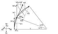
より具体的には、本形態では、ジャイロセンサーからなる慣性センサー5は、t秒(制御周期)ごとにたわみ(振動)の角速度ω1、ω2を検出する。一方、梁部材1をY軸方向に駆動する第1モーター10の角度位置は、梁部材1のY軸方向の直線的な位置に対応することから、Y軸方向の直線的な速度しか制御できず、慣性センサー5で求めた角速度とは単位が相違する。そこで、本形態では、図4を参照して以下に説明するように、角速度をX軸方向の速度とY軸方向の速度とに分解した際、慣性センサー5で求めた周速度は、梁部材1のY軸方向の直線的な速度に近似することができることから、梁部材1の振動を速度に換算してフィードバックする際、単位変換部D1は、慣性センサー5で求めた周速度を梁部材1のY軸方向の直線的な速度に単位換算する。
More specifically, in this embodiment, the
まず、振動の速度(ねじれ速度)は、
V=L・ω
L=ねじれ(回転)の半径
ω=角速度
で表されることから、
L・ω1=V1
L・ω2=V2
とする。
First, the vibration speed (torsion speed) is
V = L ・ ω
L = radius of twist (rotation)
Since ω = angular velocity,
L ・ ω1 = V1
L ・ ω2 = V2
And
ここで、振動の際の角速度は、検証実験より
ω1<500 [deg/sec]
ω2<500 [deg/sec]
であり、制御周期は125μsecであるので、
t=125μsec
である。
Here, the angular velocity during vibration is ω1 <500 [deg / sec] from the verification experiment.
ω2 <500 [deg / sec]
Since the control cycle is 125 μsec,
t = 125μsec
It is.
よって、
ω1・t<0.0625[deg]
ω2・t<0.0625[deg]
が成り立つ。
Therefore,
ω1 · t <0.0625 [deg]
ω2 · t <0.0625 [deg]
Holds.
従って、以下の式
V1=((V1x)2+(V1y)2)1/2
V1x=V1・cos(90−ω1・t)≒0
V1y=V1・sin(90−ω1・t)≒V1
V2=((V21)2+(V22)2)1/2
V21=V2・cos(90−ω2・t)≒0
V22=V2・sin(90−ω2・t)≒V2
V2′=((V2′x)2+(V2′y)2)1/2
V2′x=V2′・cos(90−ω1・t)≒0
V2′y=V2′・sin(90−ω1・t)≒V2′
より、下式が導かれる。
Therefore, the following equation V1 = ((V1x) 2 + (V1y) 2 ) 1/2
V1x = V1 · cos (90−ω1 · t) ≈0
V1y = V1 · sin (90−ω1 · t) ≈V1
V2 = ((V2 1 ) 2 + (V2 2 ) 2 ) 1/2
V2 1 = V2 · cos (90−ω2 · t) ≈0
V2 2 = V2 · sin (90−ω2 · t) ≒ V2
V2 '= ((V2'x) 2 + (V2'y) 2 ) 1/2
V2′x = V2 ′ · cos (90−ω1 · t) ≈0
V2'y = V2'.sin (90-.omega.1.t) .apprxeq.V2 '
Thus, the following formula is derived.
周速度 L・ω1=V1y
周速度 L・ω2=V2′y
よって、慣性センサー5で検出された周速度は、Y軸方向の直線的な速度として近似することができる。なお、厳密には、上記の単位変換では差異が発生するが、ゲインG1で増幅するため問題にならない。
Peripheral speed L ・ ω1 = V1y
Peripheral speed L ・ ω2 = V2′y
Therefore, the peripheral speed detected by the
(本形態の主な効果)
以上説明したように、本形態の直動ロボット100では、X軸方向に延在する梁部材1には慣性センサー5が搭載されており、第1駆動制御部15は、慣性センサー5によって梁部材1の振動を検出した結果に基づいて、第1モーター10の駆動制御を行う。このため、梁部材1の加減速を行ったときでも、梁部材1のY軸方向の振動を抑制することができるので、梁部材1に設けた吸着ヘッド4をY軸方向の所定位置に短時間のうちに停止させることができる。また、慣性センサー5によって梁部材1の振動を検出するため、梁部材1上における第2ジョイント3の位置が変わる等、使用状況が変わっても、梁部材1の振動を確実に制御することができる。
(Main effects of this form)
As described above, in the
また、梁部材1は、X軸方向における一方側X1の端部のみに第1モーター10からの駆動力が伝達されるのに対応して、慣性センサー5は、梁部材1のX軸方向における他方側X2の端部に搭載されている。このため、慣性センサー5は、速度が大きい箇所で梁部材1の振動を検出するため、感度が高い。
Further, in response to the driving force from the
また、慣性センサー5が、角速度センサーであるため、ジャイロセンサー等、汎用のセンサーを用いることができる。また、第1駆動制御部150は、慣性センサー5で検出された周速度をY軸方向の直線的な速度として用いて第1モーター10の駆動制御を行う。このため、複雑な演算を行わなくても梁部材1の振動制御を行うことができる。
Further, since the
[実施の形態1の変形例]
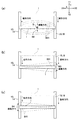
図5は、本発明の実施の形態1の変形例に係る直動ロボット100の説明図である。なお、本形態の基本的な構成は、実施の形態1と同様であるため、共通する部分には、同一の符号を付してそれらの説明を省略する。
[Modification of Embodiment 1]
FIG. 5 is an explanatory diagram of the
上記実施の形態1では、梁部材1のX軸方向の他方側X2の端部が一切、支持されていない構成であったが、本形態では、図5に示すように、梁部材1のX軸方向の他方側X2の端部を支持部材29を介して下側(Z軸方向の他方側Z2)から支持するガイド18が設けられている。このため、梁部材1は、X軸方向の一方側X1および他方側X2の両端部が支持されている。但し、第1モーター10の駆動力は、第1ジョイント2を介して梁部材1のX軸方向の一方側X1の端部のみに伝達されるため、図2を参照して説明したように、梁部材1を第1モーター10によって加減速しながらY軸方向に駆動した際、梁部材1のX軸方向の他方側X2の端部にY軸方向の振動が発生しようとする。そこで、本形態でも、実施の形態1と同様、梁部材1には、梁部材1のY軸方向の振動を検出する慣性センサー5が搭載されており、かかる慣性センサー5での検出結果を、図1(b)に示す第1駆動制御部15にフィードバックする。このため、本形態でも、実施の形態1と同様、梁部材1の加減速を行った際でも、梁部材1のY軸方向の振動を抑制することができるので、梁部材1に設けた吸着ヘッド4をY軸方向の所定位置に短時間のうちに停止させることができる。
In the first embodiment, the end of the other side X2 in the X-axis direction of the
[実施の形態2]
図6は、本発明の実施の形態2に係る直動ロボット100の説明図であり、図6(a)、(b)は、直動ロボット100の駆動機構等の説明図、および梁部材1等の平面的な構成を示す説明図である。図7は、本発明の実施の形態2に係る直動ロボット100において、梁部材1に発生しようとする振動の説明図であり、図7(a)、(b)、(c)は、梁部材1の中央が振動する様子を示す説明図、梁部材1のX軸方向の他方側X2の端部が振動する様子を示す説明図、および梁部材1のX軸方向の一方側X1の端部が振動する様子を示す説明図である。なお、本形態の基本的な構成は、実施の形態1と同様であるため、共通する部分には、同一の符号を付してそれらの説明を省略する。
[Embodiment 2]
6A and 6B are explanatory diagrams of the
上記実施の形態1では、第1モーター10の駆動力は、第1ジョイント2を介して梁部材1のX軸方向の一方側X1の端部のみに伝達される構成であったが、図6に示すように、本形態では、第1モーター10の駆動力は、梁部材1のX軸方向の一方側X1の端部および他方側X2の端部の双方に伝達される。
In the first embodiment, the driving force of the
より具体的には、梁部材1のX軸方向の一方側X1の端部および他方側X2の端部の双方に第1ジョイント2および第1ジョイント6が連結されており、第1ジョイント6に対しても、第1ジョイント2と同様、ガイド18および第1タイミングベルト機構19が設けられている。また、第1モーター10の駆動力は、第1タイミングベルト機構14と同様、第1タイミングベルト機構19にも伝達されるようになっている。
More specifically, the first joint 2 and the first joint 6 are connected to both the end on one side X1 and the end on the other side X2 of the
かかる構成の直動ロボット100において、梁部材1を第1モーター10によって加減速しながらY軸方向に駆動した際、図7(a)に矢印B2や点線B21で示すように、梁部材1の中央部にY軸方向の振動が発生すると、吸着ヘッド4を短時間のうちに定位置で停止させることができない。なお、梁部材1を第1モーター10によって加減速しながらY軸方向に駆動した際、図7(b)、(c)に矢印B3、B4や点線B31、B41で示すように、梁部材1の端部もY軸方向の振動が発生しようとするが、かかる振動は、図7(a)に示すような梁部材1の中央部での振動に比較すると小さい。
In the
そこで、本形態では、梁部材1には、梁部材1のY軸方向の振動を検出する慣性センサー5が搭載されており、かかる慣性センサー5での検出結果を、図1(b)に示す第1駆動制御部15にフィードバックするようになっている。本形態では、慣性センサー5としてジャイロセンサーが用いられており、慣性センサー5は、梁部材1のX軸方向の一方側X1の端部(第1ジョイント2)と他方側X2(第1ジョイント6)の端部との間に搭載されている。より具体的には、慣性センサー5は、梁部材1のX軸方向の一方側X1の端部と他方側X2の端部との間の中央、すなわち、第1ジョイント2と第1ジョイント6との間の中央に搭載されている。
Therefore, in this embodiment, the
このように構成した直動ロボット100でも、実施の形態1と同様、第1駆動制御部15は、慣性センサー5によって梁部材1の振動を検出した結果に基づいて、第1モーター10の駆動制御を行う。このため、梁部材1の加減速を行った際でも、梁部材1のY軸方向の振動を抑制することができるので、梁部材1に設けた吸着ヘッド4をY軸方向の所定位置に短時間のうちに停止させることができる。また、慣性センサー5によって梁部材1の振動を検出するため、梁部材1上における第2ジョイント3の位置が変わる等、使用状況が変わっても、梁部材1の振動を確実に制御することができる。
In the
また、梁部材1は、X軸方向における両方の端部に第1モーター10からの駆動力が伝達されるのに対応して、慣性センサー5は、梁部材1のX軸方向の一方側X1の端部と他方側X2の端部との間のうち、梁部材1のX軸方向の一方側X1の端部と他方側X2の端部との間の中央に搭載されている。このため、慣性センサー5は、速度が大きい箇所で梁部材1の振動を検出するため、感度が高い。
Further, in response to the driving force from the
[実施の形態3]
図8は、本発明の実施の形態3に係る直動ロボット100の説明図である。なお、本形態の基本的な構成は、実施の形態1と同様であるため、共通する部分には、同一の符号を付してそれらの説明を省略する。
[Embodiment 3]
FIG. 8 is an explanatory diagram of the
図8に示すように、本形態でも、実施の形態2と同様、第1モーター10の駆動力は、梁部材1のX軸方向の一方側X1の端部および他方側X2の端部の双方に伝達される。また、梁部材1には、梁部材1のY軸方向の振動を検出する慣性センサー5が搭載されており、かかる慣性センサー5での検出結果を、図1(b)に示す第1駆動制御部15にフィードバックするようになっている。本形態では、慣性センサー5としてジャイロセンサーが用いられており、慣性センサー5は、梁部材1のX軸方向の一方側X1の端部(第1ジョイント2)と他方側X2の端部(第1ジョイント6)との間に複数、搭載されている。
As shown in FIG. 8, also in this embodiment, the driving force of the
より具体的には、慣性センサー5は、梁部材1のX軸方向の一方側X1の端部と他方側X2の端部との間の中央、中央と梁部材1のX軸方向の一方側X1の端部(第1ジョイント2)との間、および中央と梁部材1のX軸方向の他方側X2の端部(第1ジョイント6)との間に慣性センサー5a、5b、5cとして搭載されている。また、第1駆動制御部15は、慣性センサー5a、5b、5cのうち、最も出力が大きな慣性センサー5の出力を選択して、第1モーター10の駆動制御に反映するようになっている。
More specifically, the
このように構成した直動ロボット100でも、実施の形態1、2と同様、第1駆動制御部15は、慣性センサー5によって梁部材1の振動を検出した結果に基づいて、第1モーター10の駆動制御を行う。このため、梁部材1の加減速を行った際でも、梁部材1のY軸方向の振動を抑制することができるので、梁部材1に設けた吸着ヘッド4をY軸方向の所定位置に短時間のうちに停止させることができる。また、慣性センサー5によって梁部材1の振動を検出するため、梁部材1上における第2ジョイント3の位置が変わる等、使用状況が変わっても、梁部材1の振動を確実に制御することができる。
In the
また、本形態では、梁部材1上に複数の慣性センサー5が搭載されており、第1駆動制御部15は、慣性センサー5a、5b、5cのうち、最も出力が大きな慣性センサー5の出力を選択して、第1モーター10の駆動制御に反映する。このため、梁部材1上における第2ジョイント3の位置が変わることによって、梁部材1のX軸方向のいずれかの箇所で速度が大きくなっても、梁部材1の振動を高い感度で検出するので、梁部材1の振動を確実に制御することができる。
In this embodiment, a plurality of
なお、本形態では、実施の形態2に係る直動ロボット100に複数の慣性センサー5を搭載したが、実施の形態1に係る直動ロボット100、あるいは実施の形態1の変形例に係る直動ロボット100に複数の慣性センサー5を搭載してもよい。
In the present embodiment, a plurality of
[他の実施の形態]
上記実施の形態1では、梁部材1の駆動にベルト機構を用いたが、送りねじ機構等、他の直動機構を用いた直動ロボットに本発明を適用してもよい。
[Other embodiments]
In the first embodiment, the belt mechanism is used to drive the
1・・梁部材、4・・吸着ヘッド、5、5a、5b、5c・・慣性センサー、10・・第1モーター、12・・Y軸方向駆動機構、13・・ガイド、14・・第1タイミングベルト機構、100・・直動ロボット、101・・供給エリア、102・・検査エリア、103・・排出エリア 1 .... Beam member, 4 .... Suction head, 5, 5a, 5b, 5c ... Inertial sensor, 10 .... First motor, 12 .... Y-axis direction drive mechanism, 13 .... Guide, 14 .... 1st Timing belt mechanism, 100 ... Linear motion robot, 101 ... Supply area, 102 ... Inspection area, 103 ... Discharge area
Claims (8)
該梁部材を前記第1方向と直交する第2方向に駆動する第2方向駆動用のモーターと、
前記梁部材に搭載され、当該梁部材の搭載位置での前記第2方向の速度または加速度を検出する慣性センサーと、
前記慣性センサーでの検出結果がフィードバックされ、前記モーターの駆動制御を行う駆動制御部と、
を有することを特徴とする直動ロボット。 A beam member extending in a first direction;
A second direction driving motor for driving the beam member in a second direction orthogonal to the first direction;
An inertial sensor mounted on the beam member for detecting the speed or acceleration in the second direction at the mounting position of the beam member;
A detection result from the inertial sensor is fed back, and a drive control unit that performs drive control of the motor;
A linear motion robot characterized by comprising:
前記慣性センサーは、少なくとも前記梁部材の前記第1方向における他方の端部に搭載されていることを特徴とする請求項1乃至3の何れか一項に記載の直動ロボット。 The beam member receives the driving force from the motor only at one end in the first direction,
The linear motion robot according to any one of claims 1 to 3, wherein the inertial sensor is mounted at least on the other end of the beam member in the first direction.
前記慣性センサーは、前記梁部材の前記一方の端部と前記他方の端部との間に搭載されていることを特徴とする請求項1乃至3の何れか一項に記載の直動ロボット。 The beam member is transmitted with driving force from the motor to both one end and the other end in the first direction,
The linear motion robot according to claim 1, wherein the inertial sensor is mounted between the one end portion and the other end portion of the beam member.
Priority Applications (1)
| Application Number | Priority Date | Filing Date | Title |
|---|---|---|---|
| JP2011282910A JP2013132697A (en) | 2011-12-26 | 2011-12-26 | Linear motion robot |
Applications Claiming Priority (1)
| Application Number | Priority Date | Filing Date | Title |
|---|---|---|---|
| JP2011282910A JP2013132697A (en) | 2011-12-26 | 2011-12-26 | Linear motion robot |
Publications (2)
| Publication Number | Publication Date |
|---|---|
| JP2013132697A true JP2013132697A (en) | 2013-07-08 |
| JP2013132697A5 JP2013132697A5 (en) | 2015-01-15 |
Family
ID=48909766
Family Applications (1)
| Application Number | Title | Priority Date | Filing Date |
|---|---|---|---|
| JP2011282910A Withdrawn JP2013132697A (en) | 2011-12-26 | 2011-12-26 | Linear motion robot |
Country Status (1)
| Country | Link |
|---|---|
| JP (1) | JP2013132697A (en) |
Cited By (3)
| Publication number | Priority date | Publication date | Assignee | Title |
|---|---|---|---|---|
| CN106166742A (en) * | 2016-07-29 | 2016-11-30 | 北海明杰科技有限公司 | A kind of mechanical pick-up means with pickup chip |
| JP2018001370A (en) * | 2016-07-06 | 2018-01-11 | 株式会社ダイヘン | Vibration reducing control device, and robot |
| CN107773167A (en) * | 2017-11-28 | 2018-03-09 | 瓦立智能机器人(上海)有限公司 | The contactless cleaning robot of glass curtain wall |
Citations (14)
| Publication number | Priority date | Publication date | Assignee | Title |
|---|---|---|---|---|
| JPS60141493A (en) * | 1983-12-27 | 1985-07-26 | 株式会社アマダ | Industrial robot |
| JPS6224989A (en) * | 1985-07-19 | 1987-02-02 | 株式会社 日平トヤマ | Preventive device for rocking of industrial robot |
| JPH04322995A (en) * | 1991-04-17 | 1992-11-12 | Smc Corp | Actuator |
| JPH059840U (en) * | 1991-07-20 | 1993-02-09 | 株式会社ヒロテツク | Synchronous drive mechanism |
| JPH0847882A (en) * | 1994-08-03 | 1996-02-20 | Mitsubishi Heavy Ind Ltd | Vibration damping device |
| JP2005138438A (en) * | 2003-11-06 | 2005-06-02 | Yamanashi Fuso:Kk | Formed product ejector device in forming machine and another processing machine |
| JP2006310548A (en) * | 2005-04-28 | 2006-11-09 | I-Pulse Co Ltd | Electronic component attracting nozzle, component transfer apparatus, ic handler, and surface mounting apparatus |
| JP2007127151A (en) * | 2005-11-01 | 2007-05-24 | Yamaha Motor Co Ltd | Ball nut, single shaft robot, electronic component transferring device, surface mount machine, and ic handler |
| JP2008091856A (en) * | 2006-03-22 | 2008-04-17 | Juki Corp | Electronic component mounting apparatus |
| JP2010105160A (en) * | 2010-01-15 | 2010-05-13 | Nagoya Univ | Machining device, revolution arithmetic unit of machining device, chattering vibration evaluation device of machining device and chattering vibration evaluation method of machining device |
| JP2010284726A (en) * | 2009-06-09 | 2010-12-24 | Seiko Epson Corp | Robot |
| JP2011005608A (en) * | 2009-06-29 | 2011-01-13 | Seiko Epson Corp | Conveying robot device and conveying robot device control method |
| JP2011011318A (en) * | 2009-07-06 | 2011-01-20 | Seiko Epson Corp | Position controlling method, robot |
| JPWO2011101897A1 (en) * | 2010-02-17 | 2013-06-17 | 三菱電機株式会社 | Parallel drive system |
-
2011
- 2011-12-26 JP JP2011282910A patent/JP2013132697A/en not_active Withdrawn
Patent Citations (14)
| Publication number | Priority date | Publication date | Assignee | Title |
|---|---|---|---|---|
| JPS60141493A (en) * | 1983-12-27 | 1985-07-26 | 株式会社アマダ | Industrial robot |
| JPS6224989A (en) * | 1985-07-19 | 1987-02-02 | 株式会社 日平トヤマ | Preventive device for rocking of industrial robot |
| JPH04322995A (en) * | 1991-04-17 | 1992-11-12 | Smc Corp | Actuator |
| JPH059840U (en) * | 1991-07-20 | 1993-02-09 | 株式会社ヒロテツク | Synchronous drive mechanism |
| JPH0847882A (en) * | 1994-08-03 | 1996-02-20 | Mitsubishi Heavy Ind Ltd | Vibration damping device |
| JP2005138438A (en) * | 2003-11-06 | 2005-06-02 | Yamanashi Fuso:Kk | Formed product ejector device in forming machine and another processing machine |
| JP2006310548A (en) * | 2005-04-28 | 2006-11-09 | I-Pulse Co Ltd | Electronic component attracting nozzle, component transfer apparatus, ic handler, and surface mounting apparatus |
| JP2007127151A (en) * | 2005-11-01 | 2007-05-24 | Yamaha Motor Co Ltd | Ball nut, single shaft robot, electronic component transferring device, surface mount machine, and ic handler |
| JP2008091856A (en) * | 2006-03-22 | 2008-04-17 | Juki Corp | Electronic component mounting apparatus |
| JP2010284726A (en) * | 2009-06-09 | 2010-12-24 | Seiko Epson Corp | Robot |
| JP2011005608A (en) * | 2009-06-29 | 2011-01-13 | Seiko Epson Corp | Conveying robot device and conveying robot device control method |
| JP2011011318A (en) * | 2009-07-06 | 2011-01-20 | Seiko Epson Corp | Position controlling method, robot |
| JP2010105160A (en) * | 2010-01-15 | 2010-05-13 | Nagoya Univ | Machining device, revolution arithmetic unit of machining device, chattering vibration evaluation device of machining device and chattering vibration evaluation method of machining device |
| JPWO2011101897A1 (en) * | 2010-02-17 | 2013-06-17 | 三菱電機株式会社 | Parallel drive system |
Cited By (4)
| Publication number | Priority date | Publication date | Assignee | Title |
|---|---|---|---|---|
| JP2018001370A (en) * | 2016-07-06 | 2018-01-11 | 株式会社ダイヘン | Vibration reducing control device, and robot |
| CN106166742A (en) * | 2016-07-29 | 2016-11-30 | 北海明杰科技有限公司 | A kind of mechanical pick-up means with pickup chip |
| CN107773167A (en) * | 2017-11-28 | 2018-03-09 | 瓦立智能机器人(上海)有限公司 | The contactless cleaning robot of glass curtain wall |
| CN107773167B (en) * | 2017-11-28 | 2023-02-28 | 瓦立智能机器人(上海)有限公司 | Non-contact type cleaning robot for glass curtain wall |
Similar Documents
| Publication | Publication Date | Title |
|---|---|---|
| JP4957753B2 (en) | Robot, transfer device, and control method using inertial sensor | |
| JP6008121B2 (en) | Robot and robot controller | |
| JP6575200B2 (en) | Robot, control device and robot system | |
| CN110539301A (en) | control device, robot, and robot system | |
| JP2013132697A (en) | Linear motion robot | |
| JP5929171B2 (en) | Linear motion robot | |
| US11623340B2 (en) | Robot system, control apparatus, and control method | |
| JP5521506B2 (en) | robot | |
| TWI409905B (en) | Stage device | |
| US11590648B2 (en) | Robot system, control apparatus, and control method | |
| JP2000069781A (en) | Controller for linear-direction driving mechanism | |
| JP2014121788A (en) | Robot and robot system | |
| JP5541258B2 (en) | Robot, transfer device, and control device | |
| JP5850087B2 (en) | Robot, control device and robot system | |
| JP2000005977A (en) | Controller for machine tool | |
| JP2018114593A (en) | robot | |
| JP2017148913A (en) | Robot, control device, and control method for robot | |
| JP2002168317A (en) | Ball screw drive device | |
| JP2021030326A (en) | Robot system | |
| JP2010151176A (en) | Actuator |
Legal Events
| Date | Code | Title | Description |
|---|---|---|---|
| A521 | Written amendment |
Free format text: JAPANESE INTERMEDIATE CODE: A523 Effective date: 20141119 |
|
| A621 | Written request for application examination |
Free format text: JAPANESE INTERMEDIATE CODE: A621 Effective date: 20141119 |
|
| RD04 | Notification of resignation of power of attorney |
Free format text: JAPANESE INTERMEDIATE CODE: A7424 Effective date: 20150107 |
|
| A977 | Report on retrieval |
Free format text: JAPANESE INTERMEDIATE CODE: A971007 Effective date: 20150930 |
|
| A131 | Notification of reasons for refusal |
Free format text: JAPANESE INTERMEDIATE CODE: A131 Effective date: 20151020 |
|
| A521 | Written amendment |
Free format text: JAPANESE INTERMEDIATE CODE: A523 Effective date: 20151202 |
|
| A131 | Notification of reasons for refusal |
Free format text: JAPANESE INTERMEDIATE CODE: A131 Effective date: 20160209 |
|
| A761 | Written withdrawal of application |
Free format text: JAPANESE INTERMEDIATE CODE: A761 Effective date: 20160219 |