JP2013110970A - Oil applying system - Google Patents
Oil applying system Download PDFInfo
- Publication number
- JP2013110970A JP2013110970A JP2011257032A JP2011257032A JP2013110970A JP 2013110970 A JP2013110970 A JP 2013110970A JP 2011257032 A JP2011257032 A JP 2011257032A JP 2011257032 A JP2011257032 A JP 2011257032A JP 2013110970 A JP2013110970 A JP 2013110970A
- Authority
- JP
- Japan
- Prior art keywords
- top plate
- oil
- nozzle
- nozzles
- movement mechanism
- Prior art date
- Legal status (The legal status is an assumption and is not a legal conclusion. Google has not performed a legal analysis and makes no representation as to the accuracy of the status listed.)
- Pending
Links
- 230000007246 mechanism Effects 0.000 claims abstract description 40
- 238000002347 injection Methods 0.000 claims description 22
- 239000007924 injection Substances 0.000 claims description 22
- 239000007921 spray Substances 0.000 claims description 6
- 239000003921 oil Substances 0.000 abstract description 69
- 239000008157 edible vegetable oil Substances 0.000 abstract description 20
- 238000001514 detection method Methods 0.000 abstract description 3
- 238000010276 construction Methods 0.000 abstract 1
- 239000011248 coating agent Substances 0.000 description 8
- 238000000576 coating method Methods 0.000 description 8
- 235000008429 bread Nutrition 0.000 description 6
- 230000000694 effects Effects 0.000 description 5
- 238000000034 method Methods 0.000 description 5
- 238000010586 diagram Methods 0.000 description 4
- XEEYBQQBJWHFJM-UHFFFAOYSA-N Iron Chemical compound [Fe] XEEYBQQBJWHFJM-UHFFFAOYSA-N 0.000 description 2
- 230000002093 peripheral effect Effects 0.000 description 2
- 238000004140 cleaning Methods 0.000 description 1
- 235000009508 confectionery Nutrition 0.000 description 1
- 239000008162 cooking oil Substances 0.000 description 1
- 239000000796 flavoring agent Substances 0.000 description 1
- 235000019634 flavors Nutrition 0.000 description 1
- 235000013305 food Nutrition 0.000 description 1
- 230000001771 impaired effect Effects 0.000 description 1
- 229910052742 iron Inorganic materials 0.000 description 1
- 239000004973 liquid crystal related substance Substances 0.000 description 1
- 238000005507 spraying Methods 0.000 description 1
- 239000002699 waste material Substances 0.000 description 1
Images


Landscapes
- Bakery Products And Manufacturing Methods Therefor (AREA)
- Details Or Accessories Of Spraying Plant Or Apparatus (AREA)
- Nozzles (AREA)
- Spray Control Apparatus (AREA)
Abstract
Description
本発明は油塗布装置に係り、特に、ケーキ生地等を焼成するために用いられる天板に設けられた凹状の型の内部に均一、且つ、充分に油を塗布するための油塗布装置に関する。 The present invention relates to an oil application device, and more particularly, to an oil application device for uniformly and sufficiently applying oil into a concave mold provided on a top plate used for baking cake dough and the like.
例えば、ケーキやパン等の生地を焼成する過程においては、オーブンでケーキ等の生地を焼成する前に、焦げつき防止のために天板上に設けられた凹状の型(ケーキやパン等について所望のデザインの外形を得るためのもの)内に食用油を塗布する必要がある。従来の塗布装置は、天板の上方に1個の大型スプレーガンを設けて、天板全体に食用油を噴射することにより塗布していた。 For example, in the process of baking a dough such as cake or bread, before baking the dough such as cake in an oven, a concave mold provided on the top plate to prevent burning (as desired for cakes and bread etc. It is necessary to apply edible oil in the design). A conventional coating apparatus is provided by providing one large spray gun above the top plate and spraying edible oil on the entire top plate.
また、特許文献1の油塗布装置は、平板状の天板の表面の所定位置に所望のパターンを形成するようにして食用油を噴射塗布する装置であり、例えば、ケーキ等の形状に合わせて油を塗布する必要のある場所に多数のノズルによって天板上に油を噴射して塗布する装置である。この油塗布装置は、天板上に予め複数のパン生地を載置する位置が定められており、この載置位置に向けて食用油を各ノズルから噴射して塗布する装置である。
Moreover, the oil application apparatus of
しかし、複数の凹状の型を有する天板に対して1個の大型のスプレーガンによって凹状の型に油を噴射した場合、スプレーガンから遠い位置にある型ほど油の射角(ノズルの垂直方向に対する油の噴射角度)が大きくなることから油が型の開口部の周縁部に遮られてしまい、型の内壁部分に均一、且つ、充分に油を塗布することができなかった。そのため、凹状の型内に塗布された油が不均一となってケーキ等の焼きむらが発生しやすく、歩留まりが悪いだけでなく、風味を損なう原因となっていた。また、凹状の型に均一に油を塗布しようとすると、天板のかなり上方から食用油を噴射する必要があることから油の使用量が多大なものとなり、無駄に浪費される量も多いという問題がある。さらに、油が天板の周囲にも付着するので清掃作業にも多大な負担を要していた。 However, when oil is sprayed onto a concave mold with a single large spray gun on a top plate having a plurality of concave molds, the angle of the oil (the vertical direction of the nozzle) Since the oil injection angle) is increased, the oil is blocked by the peripheral edge of the mold opening, and the oil cannot be uniformly and sufficiently applied to the inner wall portion of the mold. For this reason, the oil applied in the concave mold is not uniform, and baking unevenness of cakes and the like is likely to occur, which not only deteriorates the yield but also causes the flavor to be impaired. Also, if you try to evenly apply oil to the concave mold, you need to spray edible oil from the top of the top plate, so the amount of oil used is enormous, and there is a lot of wasted waste There's a problem. Furthermore, since the oil adheres to the periphery of the top plate, a great burden is required for the cleaning work.
また、特許文献1の油塗布装置は、複数のノズルによって平板状の天板の所定位置に所望のパターンを形成するように油を塗布する装置であり、天板の表面に設けられた凹状の型内の内壁や底面に均一、且つ、充分に油を塗布することを想定したものではない。また、ノズルから噴射する油の射角が大きいと塗布すべき所望の形状の輪郭がぼやけてしまい、油を所望の形状に塗布することが困難となる。
Moreover, the oil application apparatus of
そこで、本発明の目的は、かかる従来の装置の欠点を改良し、天板の表面に設けられた凹状の型内の内壁や底面に均一、且つ、充分に油を塗布することが可能な新規かつ独自の油塗布装置を提供することにある。 Accordingly, an object of the present invention is to improve the drawbacks of the conventional apparatus and to apply a uniform and sufficient oil to the inner wall and bottom surface of the concave mold provided on the surface of the top plate. And it is providing the original oil coating device.
上記目的を達成するため、請求項1に記載の本発明は、先端に多数の吐出孔が設けられ、所定の噴射角度の範囲内に均一に油を噴射可能なノズルを表面に凹状の型が複数配列された天板の進行方向に対して直角方向に複数配置した油噴射手段と、複数のノズルをそれぞれ水平方向へ移動させるためのノズル水平移動機構と、複数のノズルをそれぞれ上下方向へ移動させるためのノズル上下移動機構と、搬送装置によって搬送されてくる天板の位置を検知する近接センサと、近接センサによって検知した天板の位置、及び、予め記憶させてある天板の形状に関する情報に基づいて、ノズル水平移動機構及びノズル上下移動機構を動作させて各ノズルを所定位置に移動させると共に、各ノズルから油を噴射して天板上に設けられた型の内部に所定量の油を均一に塗布するようにノズルの位置及び油の噴射を制御する制御手段と、を備えていることを特徴とする。 In order to achieve the above object, according to the present invention, a plurality of discharge holes are provided at the tip, and a nozzle that can inject oil uniformly within a predetermined injection angle range has a concave mold on the surface. A plurality of oil injection means arranged in a direction perpendicular to the traveling direction of a plurality of top plates, a nozzle horizontal moving mechanism for moving the plurality of nozzles in the horizontal direction, and a plurality of nozzles moved in the vertical direction Nozzle vertical movement mechanism, proximity sensor for detecting the position of the top plate conveyed by the conveying device, position of the top plate detected by the proximity sensor, and information on the shape of the top plate stored in advance Based on the above, the nozzle horizontal movement mechanism and the nozzle vertical movement mechanism are operated to move each nozzle to a predetermined position, and oil is injected from each nozzle into the mold provided on the top plate. Characterized by comprising control means for controlling the position and oil injection nozzle, a to the oil uniformly coated.
上記目的を達成するため、請求項2に記載の本発明は、請求項1に記載の油塗布装置において、ノズルは、先端に多数の吐出孔が設けられ、垂直方向に対して約45°の範囲に均一に油を噴射するように形成されていることを特徴とする。 In order to achieve the above object, according to a second aspect of the present invention, in the oil applicator according to the first aspect, the nozzle is provided with a plurality of discharge holes at the tip, and is about 45 ° with respect to the vertical direction. It is characterized in that it is formed so as to inject oil uniformly over a range.
本発明に係る油塗布装置によれば、天板の表面に設けられた凹状の型内の内壁や底面に均一、且つ、充分に油を塗布することが可能になるという効果がある。
また、天板に設けられた型の配置に応じてノズルの位置を適宜調整可能としたので種々の天板に対応することができるという効果がある。
According to the oil application device of the present invention, there is an effect that oil can be uniformly and sufficiently applied to the inner wall and the bottom surface in the concave mold provided on the surface of the top plate.
In addition, since the position of the nozzle can be adjusted as appropriate according to the arrangement of the molds provided on the top plate, there is an effect that it can be used for various top plates.
以下、本発明に係る油塗布装置について好ましい一実施形態に基づき図面を参照しつつ詳細に説明する。
[油塗布装置の構成]
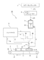
図1は本発明に係る油塗布装置の一実施形態の全体構成を示すブロック図である。図示された油塗布装置10は、概略として、天板1を水平移動させるベルトコンベア2と、天板1の型内に食用油COを噴射する複数の後述するノズル(本実施形態では8つ)を備えたノズル列(油噴射手段)3と、ノズル列3を水平移動させるノズル水平移動機構4Aと、ノズル列3を上下移動させるノズル上下移動機構4Bと、配管LP1を介して食用油COをノズル列3へ供給する加圧オイルタンク5と、配管LP2,LP3及びエアレギュレータ6を介して圧縮空気を加圧オイルタンク5へ供給するエアコンプレッサ7と、ノズル水平移動機構4A及びノズル上下移動機構4Bを制御する制御手段としてのコントローラ8と、天板3がベルトコンベア2によってノズル列3の近傍に来たことを検出する近接センサ9とを備えて構成されている。
Hereinafter, an oil coating apparatus according to the present invention will be described in detail based on a preferred embodiment with reference to the drawings.
[Configuration of oil application equipment]
FIG. 1 is a block diagram showing the overall configuration of an embodiment of an oil coating apparatus according to the present invention. The illustrated
[天板の構成]
図2(a)は天板の平面図、図2(b)は(a)のB−B線断面図である。天板1は、鉄板等を加工して形成されており、ケーキやパン等の生地を収容するための平面形状が円形状をした凹部(凹状の型)11,11が所定のパターンで複数(ここでは12個)設けられている。凹部11,11の形状は、パンやケーキ等を焼き上げた際の形状に合わせた形状となっている。そして、天板1の凹部11,11のデザインは図2に示す他、例えば図3に示すように、型を4×6の20個設けたものであってもよく、天板のサイズ(直径や深さ)、型の配列(縦横の数)等については適宜のものを採用することができる。
[Configuration of the top plate]
Fig.2 (a) is a top view of a top plate, FIG.2 (b) is BB sectional drawing of (a). The
天板1を水平移動させる搬送装置としてのベルトコンベア2は、エンドレスのベルト21と、その一端に係着されてベルト21を回転させる駆動ローラ22と、ベルト21の他端に係着されてベルト21の回転を補助する従動ローラ23とを備えて構成されている。
A
[ノズルの構成]
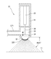
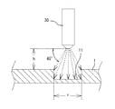
ノズル列3は、複数のノズル30,30を天板1の進行方向(搬送方向)に対して直角な方向にそれぞれ所定の間隔を有して配置した構成になっている。図4はノズル30の構成を示す正面断面図である。図示されたノズル30は、概略として、例えば直径約10mm程度の筒形状の本体31と、本体31の下端に多数の微細な吐出孔320,320が穿設された半球面状をした凸状の油噴射部32と、配管LP1を介して一時的に食用油COが蓄えられる油室33と、油室33内に配設されて油室33内の食用油COの油噴射部32への吐出を制御する開閉弁34と、本体31内の上部に配設されて開閉弁34を上下動させる駆動部35とを備えて構成されている。油噴射部32の吐出孔320は、例えば、孔径が0.1mmであり、油噴射部32に数百個が設けられている。各吐出孔320,320は油噴射部32の凸面形状の中心から放射状に配置されており、最も外側の吐出孔は食用油COの噴射角度が、例えば、水平面に対して約45°(ノズルの垂直方向に対しても約45°)となるように配置されている。この場合、図5に示すように、天板1の表面からノズル30の先端までの高さを「h」とし、凹部11の開口長さ(直径)を「r」とすれば、高さhは、凹部11の直径rの半分になる。
[数1]
tan45°=r/2/h
h=r/2
[Configuration of nozzle]
The
[Equation 1]
tan45 ° = r / 2 / h
h = r / 2
また、駆動部35は圧電式又は電磁式のアクチュエータであり、コントローラ8によって制御される。駆動部35は、そのロッド36が開閉弁34に係着しており、ロッド36の上下動に伴って開閉弁34が上下動し、開閉弁34が下方に動いて停止したときに弁閉になる。開閉弁34が開いたとき、油噴射部32の吐出孔320,320からは10〜20cm/秒の速度で食用油COが噴射される。
The
[ノズル水平移動機構及びノズル上下移動機構の構成]
図6はノズル水平移動機構4A及びノズル上下移動機構4Bの構成を示す斜視図である。ノズル水平移動機構4Aは、概略として、コ字形状を成した本体40と、水平方向に配列した複数のノズル30,30のそれぞれを所定間隔に位置させるように水平移動させるための複数の支持部材41,41と、本体40の両側間に固定されて支持部材41,41の移動をガイドするガイド棒42と、支持部材41,41の他端に設けられた複数のモータ43,43と、このモータ43,43の回転軸に取り付けられた複数のピニオン44,44と、ピニオン44,44に噛合するとともにガイド棒42に平行させて本体40に固定されたラック45とを備えて構成されている。モータ43,43を個別に正回転又は逆回転させることで支持部材41,41をガイド棒42に沿ってそれぞれ個別に移動させることができる。これによってノズル30,30の間隔を使用する天板1の種類に応じて、天板1に設けられた凹部11,11の間隔に合致させることができるようになっている。従って、図2や図3に示すようなパターンの間隔が異なる天板1が混在する場合あっても、ノズル30,30の位置を各天板1に合わせて柔軟に対応させることが可能となる。
[Configuration of nozzle horizontal movement mechanism and nozzle vertical movement mechanism]
FIG. 6 is a perspective view showing the configuration of the nozzle
一方、ノズル上下移動機構4Bは、概略として、本体40に固定させて立設された一対のスタンド46,46と、スタンド46,46の上側を連結する固定部材47と、上端が固定部材47の中間部に固定されてノズル水平移動機構4Aを昇降させる駆動部48とを備えて構成されている。これにより、天板1に設けられた凹部11の深さに応じて天板1の厚みが異なる場合であっても天板1の表面からのノズル30,30の先端までの高さ(距離)を確保することができるのでノズル30,30の高さ位置を各天板1に合わせて柔軟に対応させることが可能となる。
On the other hand, the nozzle up-and-down moving
[コントローラの構成]
図7は制御手段としてのコントローラ8の構成を示すブロック図である。コントローラ8は、概略として、中央処理装置であるCPU(又はシーケンサ)81と、天板のサイズ(縦、横、厚み)及び凹部11,11の大きさや深さパターンを記憶するメモリ82と、CPU81に接続された液晶表示器等によるタッチパネル付き表示器83と、CPU81による制御のもとにノズル水平移動機構4A及びノズル上下移動機構4Bを駆動するノズル移動回路84と、ノズル30,30のそれぞれの駆動部35を駆動するノズル駆動回路85と、駆動部35を駆動するタイミングを決定するノズル駆動タイミング発生回路86と、を備えて構成されている。CPU81はインターフェース回路等の周辺回路を含んでおり、また、図示を省略しているがコントローラ8は各回路に電源を供給する電源回路を備えている。
[Controller configuration]
FIG. 7 is a block diagram showing the configuration of the controller 8 as a control means. The controller 8 generally includes a CPU (or sequencer) 81 that is a central processing unit, a
天板1に関する情報、例えば、凹部11,11の配列や相互間の距離、凹部11の直径、天板1の厚み等に関するデータは天板1の種類ごとに予め表示器83のタッチパネルを介してメモリ82に記憶させるようになっている。この場合、異なる形状の天板1のそれぞれに番号を付し、番号を指定することで所定の天板1が特定されるようにしておけば、入力の手間を軽減することができる。また、形状の異なる複数の天板1を用いる場合には、搬送順番を予めメモリ82に登録しておくことで、どのような天板1がどのような順番で搬送されてくるかがわかるので、搬送されてくる天板1の順番に応じて適宜にノズル30,30の位置関係を制御することが可能となる。
Information relating to the
[油塗布装置の動作]
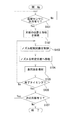
次に、図1、図6、図7及び図8等を適宜に参照して上述した油塗布装置10の動作を説明する。図8は油塗布装置10の動作例を示すフローチャートである。加圧オイルタンク5にはエアレギュレータ6を介してエアコンプレッサ7からの圧縮空気が供給されており、配管LP1を介してノズル30の油室33に食用油COが供給されるようになっている。作業者はコントローラ8の図示しない電源スイッチをオンとし、表示器83のタッチパネルを介して天板1を搬送する順番をメモリ82に記憶させる。そして、作業者が図示しないスタートボタンを押すことによりコントローラ8が動作を開始する。駆動ローラ22が回転してベルト21が回転を始めるたら作業者によってベルト21上に予め定められた順番で天板1が配置されると、天板1はベルト21の回転に伴って図1に示す矢印A方向に搬送される。天板1が近接センサ9の近傍に到達すると、近接センサ9が天板1の進行方法における天板1の端縁部を検知して検出信号を発生する(テップS101:Yes)。この検出信号はCPU81に送られ、予めメモリ82に記憶された順番における天板1に関する情報に基づいて、CPU81は先頭の天板1がノズル列3の近傍に到来したことを判断する。また、検出した天板1の順番から当該天板1の凹部11,11の配置パターンをメモリ82から検索する(ステップS102)。この検索結果に応じてCPU81はノズル移動回路84を制御し(ステップS103)、ノズル移動回路84によってノズル水平移動機構4A及びノズル上下移動機構4Bを駆動してノズル30,30を水平方向及び上下方向へ移動させ、ノズル30,30の油噴射部32を凹部11,11に対峙させる(ステップS104)。ここで、ノズル水平移動機構4Aは図6に示すモータ43,43を駆動することにより支持部材41,41を移動させ、ノズル上下移動機構4Bは駆動部48によりノズル水平移動機構4Aを昇降させることによってノズル30,30を所定位置に配置させる。
[Operation of oil applicator]
Next, the operation of the
次いで、CPU81は、予めメモリ82に記憶された天板1の形状に関する情報に基づいてノズル駆動回路85を制御して各ノズル30,30の各油噴射部32,32から油室33内に充填された食用油COを噴射させる(ステップS105)。食用油COの噴射は、凹部11,11の直径dに応じて高さhや噴射量(噴射時間の調整による)が予め設定されており、この設定された条件に従って噴射が行われる。CPU81がノズル30,30からの食用油COの噴射が終了したと判定すると(ステップS106:Yes)待機状態となり、搬送される次の天板1の有無を判定する(ステップS107)。次の天板1が無い場合(ステップS107:No)には、処理が終了となる。一方、次の天板1が有る場合(ステップS107:Yes)には、処理をステップS101に戻して同様の処理を再度実行する。
Next, the
ここで、天板1のパターンに応じてノズル30,30を移動させる理由について図9(a),(b)を参照して説明する。天板1の仕様によって凹部11,11の配列パターンや大きさが異なる。そのため、図9(a),(b)に示すように、凹部11,11の大きさや間隔は、天板1によって様々である。これに対応させるには、ノズル水平移動機構4A及びノズル上下移動機構4Bを駆動して各ノズル30,30をそれぞれ個別に移動させる必要がある。例えば、図9(a)に示すように、天板1の凹部11,11の数が少なく開口部が大きい場合には、進行方向(矢印方向)に対して直角方向における凹部11,11の配列数が1列あたり4つなので、8つのノズル30,30のうちの使用本数は半分の4つでよく、他の4つは不要となる。そこで、4つのノズル30,30を天板1の凹部11,11の間隔に合わせてそれぞれ移動させて配置し、他の4つは邪魔にならないように位置に待避させる。一方、図9(b)に示すように、凹部11,11の数が8つの場合には、ノズル30,30の使用本数は凹部11,11と同じなので、8つの全てのノズル30,30を天板1の8つの凹部11,11に対峙するようにノズル30,30の間隔を調整する必要がある。
Here, the reason why the
また、図10(a)に示すように、凹部11,11の直径が大きい場合には、ノズル上下移動機構4Bを動作させてノズル30,30の高さを高く(h1)することが必要となる。一方、図10(b)に示すように、凹部11,11の直径が小さい場合には、ノズル上下移動機構4Bを動作させてノズル30,30の高さを低く(h2)することが必要となる。この場合のノズル30,30の高さ位置(h1,h2)は天板1によって異なるので予め天板1に関する情報としてメモリ82に記憶させておくことによって凹部11,11の直径にかかわらず内壁面の全面に所定量の食用油COをムラなく均一に吹き付けることができる。
Further, as shown in FIG. 10A, when the diameters of the
[実施形態の効果]
以上のように、本発明に係る油塗布装置によれば、天板1の凹部11,11がどのように配置されていても、凹部11,11の内壁面に向けて食用油COを噴射することができるので、凹部11,11の内壁面の全域に均一に塗布することができるという効果がある。
また、凹部11,11のパターン、その数、間隔及び直径等に応じてノズル水平移動機構4A及びノズル上下移動機構4Bによってノズル30,30を水平方向及び上下方向に自由に移動できるため、様々な形状の天板1に対応になるという効果がある。
[Effect of the embodiment]
As described above, according to the oil application apparatus according to the present invention, edible oil CO is injected toward the inner wall surface of the
Further, since the
尚、本実施形態においては、ノズル30,30を横一列に8つを配置しているが、ノズル30,30の数はこれに限定されるものではなく、また、ノズル30,30は横一列に配列される必要はない。例えば、凹部11,11の間隔が狭い場合には、ノズル30,30を横一列に並べるとノズル30自体の大きさにより凹部11,11の上部に位置させることができない場合がある。そのため、ノズル30,30を段違いに配列することにより凹部11,11の間隔が狭い場合に対応させることができる。
また、本発明に係る油塗布装置は、上述した実施形態のものに限定されるものではなく、ケーキやパンの以外の焼き菓子類、あるいは、はたこ焼き等のように凹状の型への食用油の塗布が必要な食品に利用することができる。
In the present embodiment, eight
In addition, the oil coating apparatus according to the present invention is not limited to the above-described embodiment, and edible oil to a concave mold such as baked confectionery other than cake or bread, or takoyaki, etc. It can be used for foods that require coating.
1 天板
2 ベルトコンベア
3 ノズル列
4B ノズル上下移動機構
4A ノズル水平移動機構
5 加圧オイルタンク
6 エアレギュレータ
7 エアコンプレッサ
8 コントローラ
9 近接センサ
10 油塗布装置
11 凹部
21 ベルト
22 駆動ローラ
23 従動ローラ
30 ノズル
31 本体
32 油噴射部
33 油室
34 開閉弁
35 駆動部
36 ロッド
40 本体
41 支持部材
42 ガイド棒
43 モータ
44 ピニオン
45 ラック
46 スタンド
47 固定部材
48 駆動部
82 メモリ
83 タッチパネル付き表示器
84 ノズル移動回路
85 ノズル駆動回路
86 ノズル駆動タイミング発生回路
320 吐出孔
CO 食用油
d 直径
LP1 配管
LP2 配管
LP3 配管
Ts タイミング信号
DESCRIPTION OF
Claims (2)
複数の前記ノズルをそれぞれ水平方向へ移動させるためのノズル水平移動機構と、
複数の前記ノズルをそれぞれ上下方向へ移動させるためのノズル上下移動機構と、
搬送装置によって搬送されてくる前記天板の位置を検知する近接センサと、
前記近接センサによって検知した前記天板の位置、及び、予め記憶させてある前記天板の形状に関する情報に基づいて、前記ノズル水平移動機構及び前記ノズル上下移動機構を動作させて前記各ノズルを所定位置に移動させると共に、前記各ノズルから油を噴射して前記天板上に設けられた前記型の内部に所定量の油を均一に塗布するように前記ノズルの位置及び油の噴射を制御する制御手段と、
を備えていることを特徴とする油塗布装置。 A large number of discharge holes are provided at the tip, and a plurality of nozzles that can inject oil uniformly within a predetermined spray angle range are arranged in a direction perpendicular to the traveling direction of the top plate in which a plurality of concave molds are arranged on the surface Oil injection means,
A nozzle horizontal movement mechanism for moving each of the plurality of nozzles in the horizontal direction;
A nozzle vertical movement mechanism for moving each of the plurality of nozzles in the vertical direction;
A proximity sensor for detecting the position of the top plate conveyed by the conveying device;
Based on the position of the top plate detected by the proximity sensor and the information on the shape of the top plate stored in advance, the nozzle horizontal movement mechanism and the nozzle up / down movement mechanism are operated to set each nozzle in advance. The nozzle position and the oil injection are controlled so that a predetermined amount of oil is uniformly applied to the inside of the mold provided on the top plate by injecting oil from each nozzle. Control means;
An oil application apparatus comprising:
前記ノズルは、先端に多数の吐出孔が設けられ、垂直方向に対して約45°の範囲に均一に油を噴射するように形成されていることを特徴とする油塗布装置。 The oil application apparatus according to claim 1,
The nozzle is provided with a plurality of discharge holes at the tip, and is formed so as to inject oil uniformly in a range of about 45 ° with respect to the vertical direction.
Priority Applications (1)
| Application Number | Priority Date | Filing Date | Title |
|---|---|---|---|
| JP2011257032A JP2013110970A (en) | 2011-11-25 | 2011-11-25 | Oil applying system |
Applications Claiming Priority (1)
| Application Number | Priority Date | Filing Date | Title |
|---|---|---|---|
| JP2011257032A JP2013110970A (en) | 2011-11-25 | 2011-11-25 | Oil applying system |
Publications (2)
| Publication Number | Publication Date |
|---|---|
| JP2013110970A true JP2013110970A (en) | 2013-06-10 |
| JP2013110970A5 JP2013110970A5 (en) | 2014-08-07 |
Family
ID=48707185
Family Applications (1)
| Application Number | Title | Priority Date | Filing Date |
|---|---|---|---|
| JP2011257032A Pending JP2013110970A (en) | 2011-11-25 | 2011-11-25 | Oil applying system |
Country Status (1)
| Country | Link |
|---|---|
| JP (1) | JP2013110970A (en) |
Cited By (4)
| Publication number | Priority date | Publication date | Assignee | Title |
|---|---|---|---|---|
| CN104397081A (en) * | 2014-12-12 | 2015-03-11 | 中山巿顶盛食品机械有限公司 | Biscuit surface oil spraying device |
| ES2676883A1 (en) * | 2016-12-27 | 2018-07-25 | Itene, Instituto Tecnológico Del Embalaje, Transporte Y Logística | INSTALLATION TO TREAT A PLURALITY OF PACKAGING SUITABLE FOR PERISHABLE FOODS (Machine-translation by Google Translate, not legally binding) |
| CN108887305A (en) * | 2018-09-18 | 2018-11-27 | 广州酒家集团利口福食品有限公司 | A kind of intelligent robot on Production of Moon Cake line |
| JP7484595B2 (en) | 2020-09-03 | 2024-05-16 | 王子ホールディングス株式会社 | Liquid application method, method for manufacturing absorbent articles using the same, and device for manufacturing absorbent articles |
Citations (5)
| Publication number | Priority date | Publication date | Assignee | Title |
|---|---|---|---|---|
| JPS5287287A (en) * | 1976-01-17 | 1977-07-20 | Wakabayashi Kougiyou Kk | Apparatus for coating long and narrow bread case and like with oil by oil spraying inplements indivisually arranged in cross row |
| JPH05115240A (en) * | 1990-12-28 | 1993-05-14 | Yamada Seisakusho:Kk | Oil applicator for food baking mold |
| JP2002136899A (en) * | 2000-08-24 | 2002-05-14 | Lac:Kk | Oil coating applicator |
| JP2004050122A (en) * | 2002-07-23 | 2004-02-19 | Ikeuchi:Kk | Nozzle |
| JP2005270740A (en) * | 2004-03-23 | 2005-10-06 | Ykk Corp | Adhesive applying device and adhesive applying method |
-
2011
- 2011-11-25 JP JP2011257032A patent/JP2013110970A/en active Pending
Patent Citations (5)
| Publication number | Priority date | Publication date | Assignee | Title |
|---|---|---|---|---|
| JPS5287287A (en) * | 1976-01-17 | 1977-07-20 | Wakabayashi Kougiyou Kk | Apparatus for coating long and narrow bread case and like with oil by oil spraying inplements indivisually arranged in cross row |
| JPH05115240A (en) * | 1990-12-28 | 1993-05-14 | Yamada Seisakusho:Kk | Oil applicator for food baking mold |
| JP2002136899A (en) * | 2000-08-24 | 2002-05-14 | Lac:Kk | Oil coating applicator |
| JP2004050122A (en) * | 2002-07-23 | 2004-02-19 | Ikeuchi:Kk | Nozzle |
| JP2005270740A (en) * | 2004-03-23 | 2005-10-06 | Ykk Corp | Adhesive applying device and adhesive applying method |
Cited By (4)
| Publication number | Priority date | Publication date | Assignee | Title |
|---|---|---|---|---|
| CN104397081A (en) * | 2014-12-12 | 2015-03-11 | 中山巿顶盛食品机械有限公司 | Biscuit surface oil spraying device |
| ES2676883A1 (en) * | 2016-12-27 | 2018-07-25 | Itene, Instituto Tecnológico Del Embalaje, Transporte Y Logística | INSTALLATION TO TREAT A PLURALITY OF PACKAGING SUITABLE FOR PERISHABLE FOODS (Machine-translation by Google Translate, not legally binding) |
| CN108887305A (en) * | 2018-09-18 | 2018-11-27 | 广州酒家集团利口福食品有限公司 | A kind of intelligent robot on Production of Moon Cake line |
| JP7484595B2 (en) | 2020-09-03 | 2024-05-16 | 王子ホールディングス株式会社 | Liquid application method, method for manufacturing absorbent articles using the same, and device for manufacturing absorbent articles |
Similar Documents
| Publication | Publication Date | Title |
|---|---|---|
| EP2139656B1 (en) | Decoration method and system for decorating ceramic products | |
| JP2013110970A (en) | Oil applying system | |
| JP5425434B2 (en) | Method of operating a dispenser to dispense a drop of fluid material | |
| CN102762312B (en) | Desktop apparatus for work | |
| KR102425605B1 (en) | Apparatus for manufacturing red bean roll bread and method for producing red bean roll bread | |
| KR102032208B1 (en) | Apparatus for manufactruing grid for battery | |
| JP2007242833A (en) | Substrate traeting apparatus | |
| JP5202778B2 (en) | Bread coating equipment | |
| TWI569884B (en) | Coating apparatus | |
| CN102553779B (en) | High-viscosity material application device, high-viscosity material application method, high-viscosity material coating and sound insulation and antihunting board | |
| US10130981B2 (en) | Method and device for descaling a metallic surface and installation for producing semifinished metallic products | |
| JP5979782B2 (en) | Liquid applicator | |
| JP6280183B2 (en) | Nozzle device and metal press machine provided with the nozzle device | |
| KR101483521B1 (en) | Flatbed printer capable of printing curved surface | |
| JP4356806B2 (en) | Oil applicator | |
| CN102373435A (en) | Film coating equipment | |
| KR101485986B1 (en) | flow coating apparatus | |
| JP2013110970A5 (en) | ||
| KR101523671B1 (en) | Apparatus for dispensing materials and method for operating using of it | |
| KR101325481B1 (en) | Evaporating apparatus capable of making patterns | |
| TW201607613A (en) | Liquid material dropping device and method | |
| JP4139161B2 (en) | Oil applicator | |
| KR20040070022A (en) | Apparatus for applying solution and method for applying solution | |
| KR101576725B1 (en) | Soft bread auto-making equipment | |
| JP3237335U (en) | Coating equipment |
Legal Events
| Date | Code | Title | Description |
|---|---|---|---|
| A521 | Request for written amendment filed |
Free format text: JAPANESE INTERMEDIATE CODE: A523 Effective date: 20140619 |
|
| A621 | Written request for application examination |
Free format text: JAPANESE INTERMEDIATE CODE: A621 Effective date: 20140807 |
|
| A977 | Report on retrieval |
Free format text: JAPANESE INTERMEDIATE CODE: A971007 Effective date: 20150528 |
|
| A131 | Notification of reasons for refusal |
Free format text: JAPANESE INTERMEDIATE CODE: A131 Effective date: 20150609 |
|
| A02 | Decision of refusal |
Free format text: JAPANESE INTERMEDIATE CODE: A02 Effective date: 20151110 |