JP2013108572A - Friction roller type speed reducer - Google Patents

Friction roller type speed reducer Download PDF

Info

Publication number
JP2013108572A
JP2013108572A JP2011254642A JP2011254642A JP2013108572A JP 2013108572 A JP2013108572 A JP 2013108572A JP 2011254642 A JP2011254642 A JP 2011254642A JP 2011254642 A JP2011254642 A JP 2011254642A JP 2013108572 A JP2013108572 A JP 2013108572A
Authority
JP
Japan
Prior art keywords
input shaft
roller
sun roller
cam
sun
Prior art date
Legal status (The legal status is an assumption and is not a legal conclusion. Google has not performed a legal analysis and makes no representation as to the accuracy of the status listed.)
Pending
Application number
JP2011254642A
Other languages
Japanese (ja)
Other versions
JP2013108572A5 (en
Inventor
Ichiu Tanaka
一宇 田中
Yasuyuki Matsuda
靖之 松田
Hiroyasu Yoshioka
宏泰 吉岡
Current Assignee (The listed assignees may be inaccurate. Google has not performed a legal analysis and makes no representation or warranty as to the accuracy of the list.)
NSK Ltd
Original Assignee
NSK Ltd
Priority date (The priority date is an assumption and is not a legal conclusion. Google has not performed a legal analysis and makes no representation as to the accuracy of the date listed.)
Filing date
Publication date
Application filed by NSK Ltd filed Critical NSK Ltd
Priority to JP2011254642A priority Critical patent/JP2013108572A/en
Publication of JP2013108572A publication Critical patent/JP2013108572A/en
Publication of JP2013108572A5 publication Critical patent/JP2013108572A5/ja
Pending legal-status Critical Current

Links

Images

Landscapes

  • Friction Gearing (AREA)

Abstract

PROBLEM TO BE SOLVED: To achieve a structure by which surface pressure of a rolling contact part between circumferential surfaces of respective rollers 4b, 19a, 5b can be smoothly adjusted, and occurrence of metal contact leading to durability deterioration at rolling contact parts in both loading cam devices 7b, 7b can be prevented.SOLUTION: For supplying lubricating oil to a rolling element and respective cam surfaces of a drive side and a driven side constituting a loading cam device 7b, respective oil supply paths 43a, 43b, 45 on an input shaft side and cam plate side are provided to an input shaft 2b and a cam plate 15b. Among them, the oil supply path 43b on the input shaft side on a base end side of the input shaft 2b is formed while being opened to a front end side surface of a flange part 47 and inclined with respect to an axial direction of the input shaft 2b.

Description

この発明は、例えば電気自動車の駆動系に組み込んだ状態で、電動モータから駆動輪にトルクを伝達する、摩擦ローラ式減速機の改良に関する。   The present invention relates to an improvement of a friction roller type speed reducer that transmits torque from an electric motor to driving wheels in a state where the electric motor is incorporated in a driving system of an electric vehicle, for example.

[従来技術の説明]
近年普及し始めている電気自動車の利便性を向上させるべく、充電1回当りの走行可能距離を長くする為に、電動モータの効率を向上させる事が重要である。この効率を向上させるには、高速回転する小型の電動モータを使用し、この電動モータの出力軸の回転を減速してから駆動輪に伝達する事が効果がある。この場合に使用する減速機のうち、少なくとも前記電動モータの出力軸に直接繋がる第一段目の減速機は、運転速度が非常に速くなるので、運転時の振動及び騒音を抑える為に、摩擦ローラ式減速機を使用する事が考えられる。この様な場合に使用可能な摩擦ローラ式減速機として、例えば特許文献1〜3に記載されたものが知られている。このうちの特許文献3に記載された従来構造に就いて、図9〜11により説明する。
[Description of prior art]
In order to improve the convenience of electric vehicles that have begun to spread in recent years, it is important to improve the efficiency of the electric motor in order to increase the travelable distance per charge. In order to improve this efficiency, it is effective to use a small electric motor that rotates at high speed, and to reduce the rotation of the output shaft of this electric motor before transmitting it to the drive wheels. Of the speed reducers used in this case, at least the first stage speed reducer directly connected to the output shaft of the electric motor has a very high operating speed, so friction and noise during operation can be reduced. It is conceivable to use a roller speed reducer. As a friction roller type speed reducer that can be used in such a case, for example, those described in Patent Documents 1 to 3 are known. Of these, the conventional structure described in Patent Document 3 will be described with reference to FIGS.

この摩擦ローラ式減速機1は、入力軸2と、出力軸3と、太陽ローラ4と、環状ローラ5と、それぞれが中間ローラである複数個の遊星ローラ6、6と、ローディングカム装置7とを備える。
このうちの太陽ローラ4は、軸方向に分割された1対の太陽ローラ素子8a、8bを前記入力軸2の周囲に、互いの先端面同士の間に隙間を介在させた状態で互いに同心に、且つ、このうちの太陽ローラ素子8aを前記入力軸2に対する相対回転を可能に配置して成る。前記両太陽ローラ素子8a、8bの外周面は、それぞれの先端面に向かうに従って外径が小さくなる方向に傾斜した傾斜面であって、これら両傾斜面を転がり接触面としている。従ってこの転がり接触面の外径は、軸方向中間部で小さく、両端部に向かうに従って大きくなる。
The friction roller speed reducer 1 includes an input shaft 2, an output shaft 3, a sun roller 4, an annular roller 5, a plurality of planetary rollers 6 and 6, each of which is an intermediate roller, a loading cam device 7, Is provided.
Among these, the sun roller 4 is concentric with each other with a pair of sun roller elements 8a and 8b divided in the axial direction around the input shaft 2 and with a gap interposed between the tip surfaces of each other. Of these, the sun roller element 8a is arranged so as to be rotatable relative to the input shaft 2. The outer peripheral surfaces of the two sun roller elements 8a and 8b are inclined surfaces that are inclined in a direction in which the outer diameter becomes smaller toward the respective front end surfaces, and these inclined surfaces serve as rolling contact surfaces. Therefore, the outer diameter of this rolling contact surface is small at the axially intermediate portion and becomes larger toward both ends.

又、前記環状ローラ5は、全体を円環状としたもので、前記太陽ローラ4の周囲にこの太陽ローラ4と同心に配置した状態で、図示しないハウジング等の固定の部分に支持固定している。又、前記環状ローラ5の内周面は、軸方向中央部に向かうに従って内径が大きくなる方向に傾斜した転がり接触面としている。
又、前記各遊星ローラ6、6は、前記太陽ローラ4の外周面と前記環状ローラ5の内周面との間の環状空間9の円周方向複数箇所に配置している。前記各遊星ローラ6、6は、それぞれが前記入力軸2及び前記出力軸3と平行に配置された、自転軸である遊星軸10、10の周囲に、ラジアルニードル軸受を介して、回転自在に支持している。これら各遊星軸10、10の基端部は、前記出力軸3の基端部に結合固定された、支持フレームであるキャリア11に、支持固定されている。前記各遊星ローラ6、6の外周面は、母線形状が部分円弧状の凸曲面で、それぞれ前記太陽ローラ4の外周面と前記環状ローラ5の内周面とに転がり接触している。
The annular roller 5 has a circular shape as a whole, and is supported and fixed to a fixed portion such as a housing (not shown) in a state of being arranged concentrically with the sun roller 4 around the sun roller 4. . The inner peripheral surface of the annular roller 5 is a rolling contact surface inclined in a direction in which the inner diameter increases toward the axial center.
The planetary rollers 6 and 6 are disposed at a plurality of locations in the circumferential direction of the annular space 9 between the outer peripheral surface of the sun roller 4 and the inner peripheral surface of the annular roller 5. The planetary rollers 6, 6 are rotatable around planetary shafts 10, 10, which are rotation shafts, which are arranged in parallel with the input shaft 2 and the output shaft 3, respectively, via radial needle bearings. I support it. The base end portions of the planetary shafts 10 and 10 are supported and fixed to a carrier 11 that is a support frame and is fixedly coupled to the base end portion of the output shaft 3. The outer peripheral surfaces of the planetary rollers 6, 6 are convex curved surfaces having a partial arc shape on the generatrix, and are in rolling contact with the outer peripheral surface of the sun roller 4 and the inner peripheral surface of the annular roller 5, respectively.

更に、前記ローディングカム装置7は、一方の太陽ローラ素子8aと、前記入力軸2との間に設けている。この為に、この入力軸2の中間部に、止め輪12により支え環13を係止し、この支え環13と前記一方の太陽ローラ素子8aとの間に、この支え環13の側から順番に、皿ばね14と、カム板15と、それぞれが転動体である複数個の玉16、16とを設けている。そして、互いに対向する、前記一方の太陽ローラ素子8aの基端面と前記カム板15の片側面との、それぞれ円周方向複数箇所ずつに、被駆動側カム面17、17と駆動側カム面18、18とを設けている。これら各カム面17、18はそれぞれ、軸方向に関する深さが円周方向に関して中央部で最も深く、同じく両端部に向かうに従って漸次浅くなる形状を有する。   Further, the loading cam device 7 is provided between one sun roller element 8 a and the input shaft 2. For this purpose, a support ring 13 is locked to the intermediate portion of the input shaft 2 by a retaining ring 12, and the support ring 13 and the one sun roller element 8a are arranged in this order from the support ring 13 side. Further, a disc spring 14, a cam plate 15, and a plurality of balls 16, 16 each of which is a rolling element are provided. Then, the driven cam surfaces 17 and 17 and the driving cam surface 18 are respectively provided at a plurality of circumferential positions on the base end surface of the one sun roller element 8a and the one side surface of the cam plate 15 facing each other. , 18 are provided. Each of the cam surfaces 17 and 18 has a shape in which the depth in the axial direction is deepest in the central portion in the circumferential direction, and gradually becomes shallower toward both ends.

この様なローディングカム装置7は、前記入力軸2が停止している状態では、前記各玉16、16が、図11の(A)に示す様に、前記各カム面17、18の最も深くなった部分に位置する。この状態では、前記皿ばね14の弾力により、前記一方の太陽ローラ素子8aを前記他方の太陽ローラ素子8bに向け押圧する。これに対して、前記入力軸2が回転すると、前記各玉16、16が、図11の(B)に示す様に、前記各カム面17、18の浅くなった部分に移動する。そして、前記一方の太陽ローラ素子8aと前記カム板15との間隔を拡げ、前記一方の太陽ローラ素子8aを前記他方の太陽ローラ素子8bに向け押圧する。この結果、この一方の太陽ローラ素子8aはこの他方の太陽ローラ素子8bに向け、前記皿ばね14の弾力と、前記各カム面17、18に対して前記各玉16、16が乗り上げる事により発生する推力とのうちの、大きな方の力で押圧されつつ回転駆動される。   In such a loading cam device 7, when the input shaft 2 is stopped, the balls 16, 16 are deepest on the cam surfaces 17, 18 as shown in FIG. Located in the part. In this state, the one sun roller element 8a is pressed toward the other sun roller element 8b by the elasticity of the disc spring 14. On the other hand, when the input shaft 2 rotates, the balls 16 and 16 move to shallow portions of the cam surfaces 17 and 18 as shown in FIG. Then, the distance between the one sun roller element 8a and the cam plate 15 is increased, and the one sun roller element 8a is pressed toward the other sun roller element 8b. As a result, the one sun roller element 8 a is generated by the elasticity of the disc spring 14 and the balls 16, 16 riding on the cam surfaces 17, 18 toward the other sun roller element 8 b. It is driven to rotate while being pressed by the larger force of the thrust to be applied.

上述の様な摩擦ローラ式減速機1の運転時には、前記ローディングカム装置7が発生する軸方向の推力により、前記両太陽ローラ素子8a、8bの間隔が縮まる。そして、これら両太陽ローラ素子8a、8bにより構成される前記太陽ローラ4の外周面と、前記各遊星ローラ6、6の外周面との転がり接触部の面圧が上昇する。この面圧上昇に伴ってこれら各遊星ローラ6、6が、前記太陽ローラ4及び前記環状ローラ5の径方向に関して外方に押される。すると、この環状ローラ5の内周面と前記各遊星ローラ6、6の外周面との転がり接触部の面圧も上昇する。この結果、前記入力軸2と前記出力軸3との間に存在する、動力伝達に供されるべき、それぞれがトラクション部である複数の転がり接触部の面圧が、これら両軸2、3同士の間で伝達すべきトルクの大きさに応じて上昇する。   During operation of the friction roller type speed reducer 1 as described above, the distance between the two sun roller elements 8a and 8b is reduced by the axial thrust generated by the loading cam device 7. And the surface pressure of the rolling contact portion between the outer peripheral surface of the sun roller 4 constituted by both the sun roller elements 8a and 8b and the outer peripheral surface of the planetary rollers 6 and 6 increases. As the surface pressure increases, the planetary rollers 6 and 6 are pushed outward in the radial direction of the sun roller 4 and the annular roller 5. Then, the surface pressure of the rolling contact portion between the inner peripheral surface of the annular roller 5 and the outer peripheral surfaces of the planetary rollers 6 and 6 also increases. As a result, the surface pressures of the plurality of rolling contact portions, which are provided between the input shaft 2 and the output shaft 3 and are to be used for power transmission, each of which is a traction portion, are determined by It rises according to the magnitude of the torque to be transmitted between.

この状態でこの入力軸2を回転させると、この回転が、前記太陽ローラ4から前記各遊星ローラ6、6に伝わり、これら各遊星ローラ6、6がこの太陽ローラ4の周囲で、自転しつつ公転する。これら各遊星ローラ6、6の公転運動は、前記キャリア11を介して前記出力軸3により取り出せる。前記各トラクション部の面圧は、前記両軸2、3同士の間で伝達すべきトルクの大きさに応じた適正なものとなり、前記各トラクション部で過大な滑りが発生したり、或いは、これら各トラクション部の面圧が過大になる事に伴う転がり抵抗が徒に増大する事を防止できる。   When the input shaft 2 is rotated in this state, the rotation is transmitted from the sun roller 4 to the planetary rollers 6 and 6, and the planetary rollers 6 and 6 rotate around the sun roller 4. Revolve. The revolving motion of these planetary rollers 6 and 6 can be taken out by the output shaft 3 through the carrier 11. The surface pressure of each of the traction portions is appropriate according to the magnitude of torque to be transmitted between the two shafts 2 and 3, and excessive slip occurs in each of the traction portions, or these It is possible to prevent the rolling resistance from increasing due to excessive surface pressure of each traction section.

[先発明の説明]
上述の従来構造は、遊星ローラの公転運動をキャリアを介して取り出す、遊星ローラ式の摩擦ローラ式減速機であるが、環状ローラの回転を出力軸に取り出す構造によれば、キャリアを回転させずに済む。キャリアを回転させずに済む事は、各部の強度及び剛性を高くして、摩擦ローラ式減速機の耐久性を確保し易い事に加えて、各ローラの周面同士の転がり接触部である、各トラクション部等へのトラクションオイルの供給を行い易い等の利点がある。この様な、環状ローラを回転させる型式の摩擦ローラ式減速機として、特願2011−57869に係る発明がある。この先発明に係る摩擦ローラ式減速機に就いて、図12〜13により説明する。
[Description of Prior Invention]
The above-described conventional structure is a planetary roller type friction roller type speed reducer that takes out the revolving motion of the planetary roller through the carrier. However, according to the structure in which the rotation of the annular roller is taken out to the output shaft, the carrier is not rotated. It will end. The fact that it is not necessary to rotate the carrier is that the strength and rigidity of each part is increased, and in addition to ensuring the durability of the friction roller reducer, it is a rolling contact part between the peripheral surfaces of each roller. There is an advantage that it is easy to supply traction oil to each traction section or the like. As such a friction roller type speed reducer that rotates an annular roller, there is an invention according to Japanese Patent Application No. 2011-57869. The friction roller type speed reducer according to the present invention will be described with reference to FIGS.

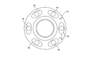
この先発明に係る摩擦ローラ式減速機1aは、入力軸2aにより太陽ローラ4aを回転駆動し、この太陽ローラ4aの回転を、複数個の中間ローラ19、19を介して環状ローラ5aに伝達し、この環状ローラ5aの回転を出力軸3aから取り出す様にしている。前記各中間ローラ19、19は、それぞれの中心部に設けた自転軸20、20を中心として自転するのみで、前記太陽ローラ4aの周囲で公転する事はない。この太陽ローラ4aは、互いに同じ形状を有する1対の太陽ローラ素子8c、8cを互いに同心に組み合わせて成り、これら両太陽ローラ素子8c、8cを軸方向両側から挟む位置に、1対のローディングカム装置7a、7aを設置している。これら各部は、軸方向中間部の径が大きく、両端部の径が小さくなった、段付円筒状のハウジング21内に収納している。   The friction roller type speed reducer 1a according to the present invention rotationally drives the sun roller 4a by the input shaft 2a, and transmits the rotation of the sun roller 4a to the annular roller 5a through a plurality of intermediate rollers 19, 19. The rotation of the annular roller 5a is taken out from the output shaft 3a. Each of the intermediate rollers 19, 19 rotates only around the rotation shafts 20, 20 provided at the center thereof, and does not revolve around the sun roller 4 a. This sun roller 4a is formed by concentrically combining a pair of sun roller elements 8c, 8c having the same shape, and a pair of loading cams at a position sandwiching both the sun roller elements 8c, 8c from both sides in the axial direction. Devices 7a and 7a are installed. Each of these parts is housed in a stepped cylindrical housing 21 in which the diameter of the intermediate part in the axial direction is large and the diameters at both ends are small.

前記入力軸2aの基半部(図12の右半部)はこのハウジング21の入力側小径円筒部22の内側に、多列玉軸受ユニット23により、前記出力軸3aは同じく出力側小径円筒部24の内側に複列玉軸受ユニット25により、それぞれ回転自在に支持している。この複列玉軸受ユニット25を構成する1対の玉軸受同士の間にラビリンスシール26を設け、外部空間側に位置する前記出力軸3aの設置部分を通じて、前記ハウジング21内に異物が入り込む事を防止している。又、この出力軸3aの基端部は、断面L字形の連結部27により、前記環状ローラ5aと連結している。   The base half of the input shaft 2a (the right half of FIG. 12) is located inside the input side small diameter cylindrical portion 22 of the housing 21 and a multi-row ball bearing unit 23, so that the output shaft 3a is also the output side small diameter cylindrical portion. Each is supported rotatably by a double row ball bearing unit 25 inside 24. A labyrinth seal 26 is provided between a pair of ball bearings constituting the double row ball bearing unit 25, and foreign matter enters the housing 21 through the installation portion of the output shaft 3a located on the outer space side. It is preventing. The base end portion of the output shaft 3a is connected to the annular roller 5a by a connecting portion 27 having an L-shaped cross section.

前記両太陽ローラ素子8c、8cは、前記入力軸2aの先半部(図12の左半部)の周囲に、この入力軸2aと同心に、この入力軸2aに対する相対回転を可能に、且つ、互いの先端面(互いに対向する面)同士の間に隙間を介在させた状態で配置している。又、前記両ローディングカム装置7a、7aを構成する1対のカム板15a、15aは、前記入力軸2aの中間部と先端部との2箇所位置で、前記両太陽ローラ素子8c、8cを軸方向両側から挟む位置に外嵌固定して、前記入力軸2aと同期して回転する様にしている。そして、互いに対向する、前記両太陽ローラ素子8c、8cの基端面と前記両カム板15a、15aの片側面との、それぞれ円周方向複数箇所ずつに、被駆動側カム面17、17と駆動側カム面18、18とを設け、これら各カム面17、18同士の間にそれぞれ玉16、16を挟持して、前記両ローディングカム装置7a、7aを構成している。前記各カム面17、18は、軸方向に関する深さが円周方向に関して漸次変化するもので、円周方向中央部で最も深く、同じく両端部に向かうに従って浅くなる。   The sun roller elements 8c, 8c are capable of rotating relative to the input shaft 2a around the front half (left half of FIG. 12) of the input shaft 2a, concentrically with the input shaft 2a, and These are arranged in a state in which a gap is interposed between the front end surfaces (surfaces facing each other). The pair of cam plates 15a and 15a constituting the both loading cam devices 7a and 7a are positioned at two positions of the intermediate portion and the tip portion of the input shaft 2a, and the sun roller elements 8c and 8c are pivoted. It is fitted and fixed at positions sandwiched from both sides in the direction so as to rotate in synchronization with the input shaft 2a. Then, the driven cam surfaces 17 and 17 are driven at a plurality of positions in the circumferential direction between the base end surfaces of the sun roller elements 8c and 8c and the one side surfaces of the cam plates 15a and 15a, which face each other. Side cam surfaces 18 and 18 are provided, and balls 16 and 16 are sandwiched between the cam surfaces 17 and 18 to constitute both loading cam devices 7a and 7a. Each of the cam surfaces 17 and 18 has a depth in the axial direction that gradually changes in the circumferential direction, and is deepest at the central portion in the circumferential direction, and also becomes shallower toward both ends.

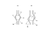
前記入力軸2aにトルクが入力されていない状態では、図13の(A)に示す様に、前記両ローディングカム装置7a、7aを構成する前記各玉16、16が、前記各カム面17、18の底部若しくは底部に近い側に存在する。この状態から、前記入力軸2aにトルクが入力される(前記摩擦ローラ式減速機1aが起動する)と、前記各玉16、16と前記各カム面17、18との係合に基づき、図13の(B)に示す様に、前記両ローディングカム装置7a、7aの軸方向厚さが増大する。そして、前記両太陽ローラ素子8c、8cが、前記摩擦ローラ式減速機1aの径方向に関して、前記各中間ローラ19の内側に食い込み、これら各中間ローラ19を、この径方向に関して外方に押す。この結果、前記各トラクション部の面圧が上昇して、これら各トラクション部に過大な滑りを発生させる事なく、前記太陽ローラ4aから前記環状ローラ5aに動力を伝達できる。尚、前記両ローディングカム装置7a、7aを構成する前記太陽ローラ素子8cと前記カム板15aとの間にばねを設けて、これら両部材8c、15a同士の間に、回転方向に関して相対回転させる方向の弾力を付している。そして、この弾力に基づき、前記各玉16、16を前記各カム面17、18の浅い側に乗り上げる傾向として、前記両ローディングカム装置7a、7aに、動力の非伝達時にも或る程度の推力を発生させている(予圧を付与している)。   In the state where torque is not input to the input shaft 2a, as shown in FIG. 13A, the balls 16, 16 constituting the loading cam devices 7a, 7a are connected to the cam surfaces 17, It exists on the bottom of 18 or the side close to the bottom. From this state, when torque is input to the input shaft 2a (the friction roller type speed reducer 1a is activated), the engagement between the balls 16 and 16 and the cam surfaces 17 and 18 As shown in FIG. 13B, the axial thicknesses of the loading cam devices 7a and 7a are increased. The sun roller elements 8c, 8c bite into the intermediate rollers 19 in the radial direction of the friction roller type speed reducer 1a, and push the intermediate rollers 19 outward in the radial direction. As a result, the surface pressure of each of the traction portions increases, and power can be transmitted from the sun roller 4a to the annular roller 5a without causing excessive slippage in the traction portions. A direction in which a spring is provided between the sun roller element 8c constituting the loading cam devices 7a, 7a and the cam plate 15a, and the members 8c, 15a are relatively rotated with respect to the rotation direction. Has the elasticity of. Based on this elasticity, the balls 16, 16 tend to run on the shallow sides of the cam surfaces 17, 18, and a certain amount of thrust is applied to the loading cam devices 7a, 7a even when power is not transmitted. Is generated (preload is applied).

前記摩擦ローラ式減速機1aの運転時に前記各中間ローラ19、19は、それぞれの自転軸20、20を中心として回転すると同時に、伝達トルクの変動に伴って前記摩擦ローラ式減速機1aの径方向に変位する。この様な、前記各中間ローラ19、19の自転及び径方向変位を円滑に行わせる為に先発明の構造の場合には、これら各中間ローラ19、19の回転中心である前記各自転軸20、20を、前記ハウジング21の内側に支持固定した支持フレーム28に対し、前記太陽ローラ4a及び前記環状ローラ5aの径方向に関する変位を可能に支持している。   At the time of operation of the friction roller type speed reducer 1a, each of the intermediate rollers 19 and 19 rotates around the respective rotation shafts 20 and 20, and at the same time, the radial direction of the friction roller type speed reducer 1a is accompanied by a change in transmission torque. It is displaced to. In the case of the structure of the previous invention in order to smoothly perform the rotation and radial displacement of the intermediate rollers 19 and 19, the rotation shafts 20 that are the rotation centers of the intermediate rollers 19 and 19. , 20 with respect to the support frame 28 that is supported and fixed inside the housing 21 so as to be capable of displacement in the radial direction of the sun roller 4a and the annular roller 5a.

上述の様に構成する先発明に係る摩擦ローラ式減速機1aの運転時に、前記入力軸2aを回転駆動すると、この入力軸2aに外嵌した前記両カム板15a、15aが回転し、前記両太陽ローラ素子8c、8cが、前記各玉16、16と前記各カム面17、18との係合に基づき、互いに近づく方向に押圧されつつ、前記入力軸2aと同方向に同じ速度で回転する。そして、前記両太陽ローラ素子8c、8cにより構成される前記太陽ローラ4aの回転が、前記各中間ローラ19、19を介して前記環状ローラ5aに伝わり、前記出力軸3aから取り出される。前記摩擦ローラ式減速機1aの運転時に、前記ハウジング21内には、トラクションオイルを循環させる為、前記各ローラ4a、19、5aの周面同士の転がり接触部(トラクション部)には、トラクションオイルの薄膜が存在する状態となる。又、これら各トラクション部の面圧は、前記両ローディングカム装置7a、7aにより適正に調節される。従って、前記摩擦ローラ式減速機1aの運転状態の変化に拘らず、前記各トラクション部で過大な滑りを発生させる事なく、動力伝達を行える。   When the input shaft 2a is rotationally driven during the operation of the friction roller type speed reducer 1a according to the previous invention configured as described above, both the cam plates 15a, 15a fitted on the input shaft 2a rotate, The sun roller elements 8c, 8c rotate at the same speed in the same direction as the input shaft 2a while being pressed toward each other based on the engagement between the balls 16, 16 and the cam surfaces 17, 18. . Then, the rotation of the sun roller 4a constituted by the both sun roller elements 8c and 8c is transmitted to the annular roller 5a through the intermediate rollers 19 and 19, and is taken out from the output shaft 3a. In order to circulate traction oil in the housing 21 during operation of the friction roller type speed reducer 1a, traction oil is provided at the rolling contact portion (traction portion) between the peripheral surfaces of the rollers 4a, 19, 5a. The thin film exists. Further, the surface pressure of each of these traction portions is appropriately adjusted by the both loading cam devices 7a and 7a. Therefore, power transmission can be performed without causing excessive slippage in each traction section, regardless of changes in the operating state of the friction roller type speed reducer 1a.

上述した先発明に係る摩擦ローラ式減速機1aの運転時に、前記入力軸2aが伝達するトルクが変動すると、前記各トラクション部の面圧を適切な値に調節する為に、前記各玉16、16が前記各カム面17、18同士の間で移動して前記両ローディングカム装置7a、7aの軸方向厚さを変化させる。又、前記各玉16、16及び前記各カム面17、18には、伝達するトルクの大きさに応じてスラスト荷重が加わる。この為、前記伝達するトルクが変動した場合に、前記各トラクション部の面圧の調節を円滑に行う為、更には転がり接触部に、金属接触に伴う著しい摩耗が発生するのを防止する為に、前記各玉16、16と前記各カム面17、18との係合部に、トラクションオイルの如き潤滑油を注ぐ(循環させる)必要がある。   When the torque transmitted by the input shaft 2a fluctuates during operation of the friction roller type speed reducer 1a according to the above-described invention, in order to adjust the surface pressure of each traction portion to an appropriate value, the balls 16, 16 moves between the cam surfaces 17, 18 to change the axial thickness of the loading cam devices 7a, 7a. A thrust load is applied to the balls 16 and 16 and the cam surfaces 17 and 18 according to the magnitude of torque to be transmitted. For this reason, in order to smoothly adjust the surface pressure of each traction portion when the torque to be transmitted fluctuates, and to prevent the rolling contact portion from being significantly worn due to metal contact. It is necessary to pour (circulate) lubricating oil such as traction oil into the engaging portions between the balls 16 and 16 and the cam surfaces 17 and 18.

特開昭59−187154号公報JP 59-187154 A 特開昭61−136053号公報JP-A-61-136053 特開2004−116670号公報JP 2004-116670 A

本発明は、上述の様な事情に鑑みて、入力軸が伝達するトルクが変動した場合に、各ローラの周面同士の転がり接触部の面圧の調節を円滑に行う事ができ、しかも、これら各転がり接触部で金属接触が発生するのを防止できる摩擦ローラ式減速機を実現すべく発明したものである。   In the present invention, in view of the circumstances as described above, when the torque transmitted by the input shaft fluctuates, it is possible to smoothly adjust the surface pressure of the rolling contact portion between the peripheral surfaces of the rollers, The invention has been invented to realize a friction roller type speed reducer that can prevent metal contact from occurring at each of the rolling contact portions.

本発明の摩擦ローラ式減速機は、前述した従来から知られている摩擦ローラ式減速機と同様に、出力軸と、太陽ローラと、環状ローラと、複数個の中間ローラと、ローディングカム装置とを備える。
特に、本発明の摩擦ローラ式減速機に於いては、前記ローディングカム装置を構成するカム板を、前記入力軸の基端側の大径部と、先端側の小径部との間の段差面に突き当てた状態で、この入力軸に対し固定している。そして、前記カム板と前記入力軸とに、前記ローディングカム装置を構成する各転動体に潤滑油を供給する為の給油通路を1乃至複数箇所にそれぞれ設けており、前記入力軸の内部に設けた潤滑油流路を通じて、前記各給油通路に潤滑油を送り込み自在としている。そして、これら各給油通路のうち、前記入力軸側の給油通路を、前記段差面に開口し、この入力軸の軸方向に対して傾斜した状態で設けている。
The friction roller type speed reducer of the present invention is similar to the previously known friction roller type speed reducer, and includes an output shaft, a sun roller, an annular roller, a plurality of intermediate rollers, and a loading cam device. Is provided.
In particular, in the friction roller type speed reducer according to the present invention, the cam plate constituting the loading cam device has a step surface between a large diameter portion on the proximal end side of the input shaft and a small diameter portion on the distal end side. In this state, it is fixed to this input shaft. The cam plate and the input shaft are provided with one or a plurality of oil supply passages for supplying lubricating oil to the rolling elements constituting the loading cam device, and are provided inside the input shaft. The lubricating oil can be freely fed into each of the oil supply passages through the lubricating oil passage. Of these oil supply passages, the oil supply passage on the input shaft side is opened in the stepped surface and provided in a state inclined with respect to the axial direction of the input shaft.

上述の様に構成する本発明の摩擦ローラ式減速機によれば、各ローラの周面同士の転がり接触部(トラクション部)の面圧の調節を円滑に行う事ができ、しかも優れた耐久性を有する摩擦ローラ式減速機を実現できる。即ち、ローディングカム装置を構成し、発熱量の多い転動体と各カム面との転がり接触部に、入力軸及びカム板に設けた給油通路を介して潤滑油を供給する事で、この入力軸が伝達するトルクが変動した場合に、前記面圧の調節を円滑に行わせると共に、前記各転がり接触部で、金属接触に基づく著しい摩耗が発生するのを防止できる。   According to the friction roller type speed reducer of the present invention configured as described above, the surface pressure of the rolling contact portion (traction portion) between the peripheral surfaces of each roller can be adjusted smoothly, and excellent durability is achieved. It is possible to realize a friction roller type speed reducer having That is, the loading cam device is configured, and the lubricating oil is supplied to the rolling contact portion between the rolling element that generates a large amount of heat and each cam surface through the oil supply passage provided in the input shaft and the cam plate. When the torque transmitted by the motor fluctuates, the surface pressure can be adjusted smoothly, and at the respective rolling contact portions, the occurrence of significant wear due to metal contact can be prevented.

本発明の摩擦ローラ式減速機を組み込んだ、電気自動車用駆動装置の動力伝達装置を示す断面図。Sectional drawing which shows the power transmission device of the drive device for electric vehicles incorporating the friction roller type reduction gear of this invention. 図1のa部拡大図。The a section enlarged view of FIG. 図1の右方から見た図。The figure seen from the right side of FIG. 摩擦ローラ式減速機を取り出し、太陽ローラ及び環状ローラを省略して、図1の右上方から見た状態で示す斜視図。The perspective view shown in the state which took out the friction roller type reduction gear, abbreviate | omitted the sun roller and the annular roller, and was seen from the upper right of FIG. 同じく図1の右方から見た正投影図。The orthographic view seen from the right side of FIG. 同じく図5の左方から見た正投影図。The orthographic view seen from the left of FIG. 図6のb−b断面図。Bb sectional drawing of FIG. 入力軸側給油通路を形成する方向によって生じる問題を説明する為の、略断面図。The schematic sectional drawing for demonstrating the problem which arises by the direction which forms the input shaft side oil supply path. 従来から知られている摩擦ローラ式減速機の1例を示す断面図。Sectional drawing which shows an example of the friction roller type reduction gear conventionally known. 一部を省略して示す、図9のc−c断面図。FIG. 10 is a cross-sectional view taken along the line cc of FIG. ローディングカム装置が推力を発生していない状態(A)と同じく発生している状態(B)とをそれぞれ示す、図10のd−d断面に相当する模式図。The schematic diagram equivalent to the dd cross section of FIG. 10 which each shows the state (B) which has generate | occur | produced similarly to the state (A) in which the loading cam apparatus is not generating thrust. 先発明に係る摩擦ローラ式減速機の断面図。Sectional drawing of the friction roller type reduction gear which concerns on a prior invention. ローディングカム装置の作用に基づいて中間ローラが変位する状況を、トルクの非伝達時(A)と伝達時(B)とで示す模式図。The schematic diagram which shows the condition where an intermediate | middle roller displaces based on the effect | action of a loading cam apparatus at the time of non-transmission of a torque (A) and transmission (B).

[実施の形態の1例]
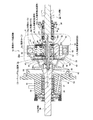
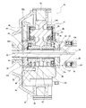
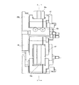
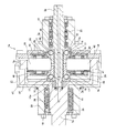
図1〜7は、本発明の実施の形態の1例を示している。本例の摩擦ローラ式減速機1bは、図12に示したハウジング21の如き減速機ケース内に収納される。そして、この減速機ケース外に設けた、図示しない電動モータの駆動軸に結合した入力軸2bにより太陽ローラ4bを回転駆動し、この太陽ローラ4bの回転を、複数個の中間ローラ19a、19aを介して環状ローラ5bに伝達し、この環状ローラ5bの回転を、出力軸3bを通じて取り出す様にしている。この出力軸3bを設置する為、前記減速機ケースの一端側壁部に軸受ケース29を、油密に固定する。そして、この軸受ケース29の内径側に前記出力軸3bを、出力側転がり軸受ユニット30と出力側シーリングユニット31とにより、油密を保持した状態で、回転自在に支持している。前記出力軸3bと前記環状ローラ5bとは、互いに同心に配置した状態で同期して回転する様に、連結ブラケット32により結合している。前記環状ローラ5bは、修理・交換作業を容易に行う事ができる様に前記連結ブラケット32に支持されているが、その構造に就いては、本発明の要旨と関係しない為、詳しい説明は省略する。
[Example of Embodiment]
1 to 7 show an example of an embodiment of the present invention. The friction roller type speed reducer 1b of this example is housed in a speed reducer case such as the housing 21 shown in FIG. Then, the sun roller 4b is rotationally driven by an input shaft 2b that is provided outside the speed reducer case and is coupled to a drive shaft of an electric motor (not shown), and the rotation of the sun roller 4b is caused by rotating a plurality of intermediate rollers 19a and 19a. The rotation of the annular roller 5b is taken out through the output shaft 3b. In order to install the output shaft 3b, a bearing case 29 is oil-tightly fixed to one end side wall portion of the speed reducer case. The output shaft 3b is rotatably supported by the output side rolling bearing unit 30 and the output side sealing unit 31 on the inner diameter side of the bearing case 29 while maintaining oil tightness. The output shaft 3b and the annular roller 5b are coupled by a connecting bracket 32 so as to rotate synchronously while being arranged concentrically with each other. The annular roller 5b is supported by the connecting bracket 32 so that repair and replacement work can be easily performed. However, the structure of the annular roller 5b is not related to the gist of the present invention, and thus detailed description thereof is omitted. To do.

前記入力軸2bは、前記減速機ケースの他端側壁部(図示せず)の内側に、入力側転がり軸受ユニット33と入力側シーリングユニット34とにより、油密を保持した状態で、回転自在に支持している。そして、前記入力軸2bの先端部に、前記太陽ローラ4bを設けて、この入力軸2bによりこの太陽ローラ5bを回転駆動する様にしている。この太陽ローラ4bは、前述の図12〜13に示した先発明構造の場合と同様に、互いに対称な形状を有する1対の太陽ローラ素子8d、8dから成り、前記入力軸2bの先半部(図1の左半部)に設けた小径部35の周囲に配置している。又、これら両太陽ローラ素子8d、8dと前記入力軸2bとの間にそれぞれローディングカム装置7b、7bを設け、これら両太陽ローラ素子8d、8dを互いに近付く方向に押圧しつつ、これら両太陽ローラ素子8d、8dを前記入力軸2bにより回転駆動する様にしている。即ち、前記両ローディングカム装置7b、7bを構成するカム板15b、15bをそれぞれ前記小径部35に対し締り嵌め外嵌固定して、前記入力軸2bと共に回転する様にしている。又、前記両カム板15b、15bの互いに反対側面を、前記小径部35と、前記入力軸2bの基半部(図1〜2の右半部)に設けた大径部36との間に形成した鍔部37、又は、この入力軸2bの先端部に螺合固定したローディングナット38にそれぞれ突き当てている。そして、互いに対向する、前記両太陽ローラ素子8d、8dの基端面と前記両カム板15b、15bの片側面との、それぞれ円周方向複数箇所ずつに、前述の図12〜13に示した先発明構造の場合と同様に、被駆動側カム面17、17と駆動側カム面18、18とを設け、これら各カム面17、18同士の間にそれぞれ玉16、16を狭持している。尚、前記両ローディングカム装置7b、7bには、それぞれ複数ずつの被駆動側、駆動側各カム面及び玉に加えて、予圧付与の為のばねを設けている。このばねは、前記両カム板15b、15bと前記両太陽ローラ素子8d、8dとを相対回転する方向に押圧し、前記各玉16、16を前記各カム面17、18の浅い側に移動させる。この部分の構造に関しては、本発明の要旨とは関係しないし、別の構造を採用する事もできる。   The input shaft 2b is rotatable inside the other end side wall (not shown) of the speed reducer case while maintaining oil tightness by an input side rolling bearing unit 33 and an input side sealing unit 34. I support it. The sun roller 4b is provided at the tip of the input shaft 2b, and the sun roller 5b is rotationally driven by the input shaft 2b. This sun roller 4b is composed of a pair of sun roller elements 8d and 8d having symmetrical shapes as in the case of the prior invention structure shown in FIGS. 12 to 13, and the front half of the input shaft 2b. It arrange | positions around the small diameter part 35 provided in (left half part of FIG. 1). Further, loading cam devices 7b and 7b are provided between the sun roller elements 8d and 8d and the input shaft 2b, respectively, and these sun roller elements 8d and 8d are pressed in a direction approaching each other. The elements 8d and 8d are driven to rotate by the input shaft 2b. That is, the cam plates 15b and 15b constituting the loading cam devices 7b and 7b are respectively fitted and fixed to the small diameter portion 35 so as to rotate together with the input shaft 2b. The opposite side surfaces of the cam plates 15b and 15b are located between the small diameter portion 35 and the large diameter portion 36 provided in the base half portion (the right half portion in FIGS. 1 and 2) of the input shaft 2b. The flange 37 is abutted against the formed loading nut 38 or the loading nut 38 screwed and fixed to the tip of the input shaft 2b. Then, the tip shown in FIGS. 12 to 13 described above is provided at each of a plurality of positions in the circumferential direction on the base end surfaces of the sun roller elements 8d and 8d and the one side surfaces of the cam plates 15b and 15b. As in the case of the inventive structure, the driven cam surfaces 17 and 17 and the driving cam surfaces 18 and 18 are provided, and the balls 16 and 16 are sandwiched between the cam surfaces 17 and 18, respectively. . Each of the loading cam devices 7b and 7b is provided with a spring for applying a preload in addition to a plurality of driven side, driving side cam surfaces and balls. This spring presses both the cam plates 15b, 15b and the both sun roller elements 8d, 8d in the direction of relative rotation, and moves the balls 16, 16 to the shallow side of the cam surfaces 17, 18. . The structure of this part is not related to the gist of the present invention, and another structure can be adopted.

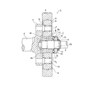
本例の場合には、各摺動部に潤滑油を供給する為に、前記入力軸2bの内部に入力軸側潤滑油流路39を、前記出力軸3bの内部に出力軸側潤滑油流路40をそれぞれ設けている。この出力軸3bの軸方向中間部に形成した給油口41から送り込まれた潤滑油は、前記入力軸側、出力軸側両潤滑油流路39、40を通って前記各摺動部に送り込まれる。即ち、前記給油口41からこの出力軸側潤滑油流路40に送り込まれた潤滑油は、ノズル53から前記入力軸側潤滑油流路39内に送り込まれ、前記各玉16、16及び前記各カム面17、18を潤滑する。即ち、前記入力軸2bに形成した入力軸側給油通路43a、43bを介して、前記両ローディングカム装置7b、7bを構成するカム板15b、15bと、前記鍔部37、又は前記ローディングナット38との間部分に設けられた環状の空間44、44に、前記入力側潤滑油流路39内に送り込まれた潤滑油を送り込む。更に、これら両空間44、44に送り込まれた潤滑油を、前記両カム板15b、15bの軸方向に形成したカム板側給油通路45、45を介し、前記各玉16、16の転動面と前記各カム面17、18との転がり接触部(図12〜13参照)に送り込む。この様なカム板側給油通路45、45は、前記両カム板15b、15bに前記各玉16、16と同数ずつ、前記各駆動側カム面18、18を形成した位置から円周方向にずらせた位置に等間隔に、軸方向に形成している。或いは、前記両カム板15b、15bの外径が大きく、前記各駆動側カム面18、18が径方向外方に位置する場合には、前記各カム板側給油通路45、45をこれら各駆動側カム面18、18の径方向内方に形成する事もできる。又、前記ノズル53から吐出され、前記入力軸側潤滑油流路39内に入り切れなかった潤滑油は、前記出力軸3bの基端面に開口する状態で設けられた円形凹部54内に入り込み、この円形凹部54の内周面と、前記入力軸2bの先端部外周面との間に設けたラジアルニードル軸受42を潤滑する。   In the case of this example, in order to supply lubricating oil to each sliding portion, the input shaft side lubricating oil flow path 39 is provided inside the input shaft 2b, and the output shaft side lubricating oil flow is provided inside the output shaft 3b. Each path 40 is provided. Lubricating oil sent from an oil supply port 41 formed in the axial direction intermediate portion of the output shaft 3b is sent to each sliding portion through both the input shaft side and output shaft side lubricating oil passages 39, 40. . That is, the lubricating oil sent from the oil supply port 41 to the output shaft side lubricating oil flow path 40 is sent from the nozzle 53 into the input shaft side lubricating oil flow path 39, and the balls 16, 16 and the The cam surfaces 17 and 18 are lubricated. That is, via the input shaft side oil supply passages 43a, 43b formed in the input shaft 2b, the cam plates 15b, 15b constituting the both loading cam devices 7b, 7b, the flange portion 37, or the loading nut 38, Lubricating oil fed into the input-side lubricating oil passage 39 is fed into annular spaces 44, 44 provided in the intermediate portion. Further, the lubricating oil fed into both the spaces 44, 44 passes through the cam plate side oil supply passages 45, 45 formed in the axial direction of the both cam plates 15b, 15b, and the rolling surfaces of the balls 16, 16 are moved. And the respective cam surfaces 17 and 18 are fed into rolling contact portions (see FIGS. 12 to 13). Such cam plate side oil supply passages 45, 45 are shifted in the circumferential direction from the positions where the respective drive side cam surfaces 18, 18 are formed in the same number of the balls 16, 16 in the both cam plates 15 b, 15 b. Are formed at equal intervals in the axial direction. Alternatively, when the outer diameters of both the cam plates 15b, 15b are large and the drive-side cam surfaces 18, 18 are located radially outward, the cam plate-side oil supply passages 45, 45 are driven by the respective drive plates. It can also be formed radially inward of the side cam surfaces 18, 18. Further, the lubricating oil discharged from the nozzle 53 and not fully entering the input shaft side lubricating oil flow path 39 enters a circular recess 54 provided in an open state on the base end surface of the output shaft 3b, The radial needle bearing 42 provided between the inner peripheral surface of the circular recess 54 and the outer peripheral surface of the tip end portion of the input shaft 2b is lubricated.

前記両入力軸側給油通路43a、43bのうち、前記入力軸2bの先端側の入力軸側給油通路43aは、前記小径部35の軸方向中間部に径方向に形成している。一方、同じく基端側の入力軸側給油通路43bは、特許請求の範囲に記載した段差面である前記鍔部37の先端側面に開口し、前記入力軸2bの軸方向に関し先端側に向かう程径方向外方に傾斜した状態で形成している。この様な入力軸側給油通路43a、43bは、前記各玉16、16及び前記各カム面17、18に送り込む潤滑油の量に応じて、円周方向に1乃至複数箇所ずつ設ける事ができる。又、前記両入力軸側給油通路43a、43bの内径寸法に就いても、前記各玉16、16及び前記各カム面17、18に送り込む潤滑油の量に応じて決定する。   Of the two input shaft side oil supply passages 43 a and 43 b, the input shaft side oil supply passage 43 a on the distal end side of the input shaft 2 b is formed in a radial direction at an axially intermediate portion of the small diameter portion 35. On the other hand, the input shaft side oil supply passage 43b on the base end side is also opened at the front end side surface of the flange portion 37, which is the stepped surface described in the claims, and is closer to the front end side in the axial direction of the input shaft 2b. It is formed in a state inclined radially outward. Such input shaft side oil supply passages 43a and 43b can be provided in one or more places in the circumferential direction according to the amount of lubricating oil fed into the balls 16 and 16 and the cam surfaces 17 and 18, respectively. . The inner diameters of the input shaft side oil supply passages 43a and 43b are determined according to the amount of lubricating oil fed to the balls 16 and 16 and the cam surfaces 17 and 18, respectively.

尚、前記両カム板15b、15bの外周縁に、その内周面を前記両太陽ローラ素子8d、8dの基端部外周面に対向させた庇部46、46を設け、前記カム板側給油通路45、45から前記各玉16、16及び前記各カム面17、18に送り込まれた潤滑油が、径方向外方に漏れ出すのを防止する事もできる。即ち、前記両庇部46、46の内周面を前記両太陽ローラ素子8d、8dの基端部外周面に近接対向させる事により、前記両カム板15b、15bとこれら両太陽ローラ素子8d、8dとの間にラビリンスシールを構成する。或いは、前記両庇部46、46の内周面を、前記両カム板15b、15bの基端部外周面に形成した凹溝に装着したOリングに摺接させ、接触シールとしても良い。前記両庇部46、46の軸方向寸法は、前記両ローディングカム装置7b、7bの軸方向厚さが最も厚くなった状態に於いても、前記両庇部46、46の先端縁が前記両太陽ローラ素子8d、8dの基端部外周面に対向する様に規制している。
尚、庇部をこれら両太陽ローラ素子8d、8dの基端側外周縁に形成し、内周面を前記両カム板15b、15bの外周面に対向させる様に構成する事もできる。何れにしても、上述の様な庇部を設ける場合には、この庇部と、次述する揺動フレーム47、47等の他の部材とが干渉しない様にする必要がある。従って、上述の様な庇部46、46は、前記両太陽ローラ素子8d、8dと前記両カム板15bと15bとの外径側端部同士の隙間を十分に狭くして、前記両ローディングカム装置7b、7b内に十分量の潤滑油を供給できるのであれば、必ずしも設ける必要はない。
The cam plate side oil supply is provided on the outer peripheral edge of the cam plates 15b, 15b with flanges 46, 46 having their inner peripheral surfaces opposed to the outer peripheral surfaces of the base end portions of the sun roller elements 8d, 8d. It is also possible to prevent the lubricating oil fed from the passages 45, 45 to the balls 16, 16 and the cam surfaces 17, 18 from leaking radially outward. That is, the cam plates 15b and 15b and the sun roller elements 8d, 8d, and the sun roller elements 8d, by making the inner peripheral surfaces of the flanges 46 and 46 close to and face the outer peripheral surfaces of the base end portions of the sun roller elements 8d and 8d. A labyrinth seal is formed between 8d. Alternatively, the inner peripheral surfaces of the both flange portions 46, 46 may be slidably contacted with O-rings mounted in concave grooves formed on the outer peripheral surfaces of the base end portions of the cam plates 15b, 15b to form a contact seal. The axial dimensions of the both flange portions 46, 46 are such that the leading edges of the both flange portions 46, 46 are located at both ends even when the axial thickness of the loading cam devices 7b, 7b is the largest. The solar roller elements 8d and 8d are regulated so as to face the outer peripheral surface of the base end portion.
It should be noted that the collar portion may be formed on the outer peripheral edge of the base end side of both the sun roller elements 8d, 8d, and the inner peripheral surface may be opposed to the outer peripheral surfaces of the both cam plates 15b, 15b. In any case, when providing the above-described collar portion, it is necessary to prevent this collar portion from interfering with other members such as the swing frames 47 and 47 described below. Accordingly, the flanges 46, 46 as described above have a sufficiently small gap between the outer diameter side ends of the sun roller elements 8d, 8d and the cam plates 15b, 15b, so If a sufficient amount of lubricating oil can be supplied into the devices 7b and 7b, it is not necessarily provided.

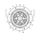
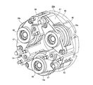
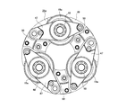
又、前記各中間ローラ19a、19aは、前記減速機ケース内に支持固定される支持フレーム28aに対し、回転及びこの支持フレーム28aの径方向に関する若干の変位を可能に支持している。この径方向変位を可能にする理由は、前記両ローディングカム装置7b、7bに作用により前記両太陽ローラ素子8d、8dが互いに近付き、前記各中間ローラ19a、19aが前記支持フレーム28aの径方向外方に押圧された場合に、これら各中間ローラ19a、19aの変位を円滑に許容する為である。この様な理由で、前記径方向に関する変位を可能にする為の構造に就いては、例えば前記支持フレーム28aに対してそれぞれの基端部を枢支した揺動フレーム47、47の中間部に前記各中間ローラ19a、19aを、玉軸受48、48により回転自在に支持する構造を採用できる。或いは、前記支持フレーム28aに形成した径方向に長い長孔の内側に、前記各中間ローラ19a、19aの両端部に設けた玉軸受48、48の外輪を緩く内嵌する構造を採用する事もできる。何れにしても、前記径方向の変位を可能にする構造に関しては、本発明の要旨とは関係しない為、詳しい説明は省略する。   The intermediate rollers 19a and 19a support the support frame 28a supported and fixed in the speed reducer case so as to be able to rotate and slightly displace in the radial direction of the support frame 28a. The reason why this radial displacement is possible is that the sun roller elements 8d and 8d approach each other due to the action of the loading cam devices 7b and 7b, and the intermediate rollers 19a and 19a are located radially outside the support frame 28a. This is because the displacement of each of the intermediate rollers 19a, 19a is allowed smoothly when pressed in the opposite direction. For this reason, the structure for enabling the displacement in the radial direction is, for example, in the middle part of the swing frames 47, 47 pivotally supporting the respective base end parts with respect to the support frame 28a. A structure in which the intermediate rollers 19a and 19a are rotatably supported by ball bearings 48 and 48 can be employed. Alternatively, it is also possible to adopt a structure in which the outer rings of the ball bearings 48, 48 provided at both ends of the intermediate rollers 19a, 19a are loosely fitted inside the long holes in the radial direction formed in the support frame 28a. it can. In any case, the structure that enables the radial displacement is not related to the gist of the present invention, and a detailed description thereof will be omitted.

又、前記支持フレーム28aの円輪状の連結部49の軸方向片側面の円周方向等間隔複数箇所(図示の例では3箇所)から前記各中間ローラ19a、19aの設置側に向けて、前記支持フレーム28aの軸方向に対し平行に突出した柱部50、50を設けている。そして、これら各柱部50、50の内側に、トラクションオイルの供給路51、51を設けて、前記各中間ローラ19a、19aの外周面と、前記太陽ローラ4bの外周面及び前記環状ローラ5bの内周面との転がり接触部(トラクション部)に、トラクションオイルを送り込める様にしている。この様な潤滑剤の供給路51、51に関しても、前記各トラクション部に必要とされるトラクションオイルを供給できる構造であれば良く、本発明の要旨とも関係しない為、図示のみで、詳しい説明は省略する。   Also, from the plural circumferentially equidistantly spaced locations (three locations in the illustrated example) on the one axial side surface of the annular connecting portion 49 of the support frame 28a toward the installation side of the intermediate rollers 19a, 19a, Column portions 50 and 50 projecting parallel to the axial direction of the support frame 28a are provided. And inside these each pillar part 50 and 50, the supply path 51, 51 of traction oil is provided, the outer peripheral surface of each said intermediate | middle roller 19a, 19a, the outer peripheral surface of the said sun roller 4b, and the said annular roller 5b Traction oil can be sent to the rolling contact part (traction part) with the inner peripheral surface. Such a lubricant supply path 51, 51 may be any structure that can supply the traction oil required for each traction section, and is not related to the gist of the present invention. Omitted.

電気自動車用駆動装置等に組み込んだ摩擦ローラ式減速機1bの運転時には、図示しない電動モータにより前記入力軸2bを介して、前記太陽ローラ4bを回転駆動する。この太陽ローラ4bの回転は、前記各中間ローラ19a、19aを介して前記環状ローラ5bに伝わる。この太陽ローラ4bを構成する、前記両太陽ローラ素子8d、8dには、予圧ばねを組み込んで成る前記両ローディングカム装置7b、7bにより、互いに近付く方向の予圧が付与されている。従って、前記各ローラ4b、19a、5bの周面同士の転がり接触部(トラクション部)の面圧は、これら各ローラ4b、19a、5b同士の間でトルクを伝達しない状態でも或る程度確保されている。又、これら各ローラ4b、19a、5b同士の間で伝達するトルクが大きくなると、前記両ローディングカム装置7b、7bが前記両太陽ローラ素子8d、8d同士を互いに近付ける方向に押圧する力(推力)が大きくなり、前記各トラクション部の面圧が更に高くなる。前記各中間ローラ19a、19aは、前記支持フレーム28aに、径方向の変位を可能に支持されている為、これら各中間ローラ19a、19aの外周面と、前記太陽ローラ4bの外周面及び前記環状ローラ5bの内周面との転がり接触部の面圧は、効果的に上昇する。この結果、前記各ローラ4b、19a、5b同士の間で伝達するトルクの変動に拘らず、前記太陽ローラ4bから前記環状ローラ5bへの動力伝達を効率良く行える。この様にしてこの環状ローラ5bに伝達された動力は、前記連結ブラケット32を介して前記出力軸3bに伝達される。   During operation of the friction roller type reduction gear 1b incorporated in a drive device for an electric vehicle or the like, the sun roller 4b is rotationally driven by the electric motor (not shown) via the input shaft 2b. The rotation of the sun roller 4b is transmitted to the annular roller 5b through the intermediate rollers 19a and 19a. The sun roller elements 8d and 8d constituting the sun roller 4b are preloaded in a direction approaching each other by the loading cam devices 7b and 7b each incorporating a preload spring. Accordingly, the surface pressure of the rolling contact portion (traction portion) between the peripheral surfaces of the rollers 4b, 19a, and 5b is ensured to some extent even when no torque is transmitted between the rollers 4b, 19a, and 5b. ing. Further, when the torque transmitted between the rollers 4b, 19a, and 5b increases, the force (thrust) that the loading cam devices 7b and 7b press the sun roller elements 8d and 8d closer to each other. Increases, and the surface pressure of each of the traction portions is further increased. Since each of the intermediate rollers 19a and 19a is supported by the support frame 28a so as to be capable of radial displacement, the outer peripheral surface of each of the intermediate rollers 19a and 19a, the outer peripheral surface of the sun roller 4b, and the annular The surface pressure of the rolling contact portion with the inner peripheral surface of the roller 5b effectively increases. As a result, power transmission from the sun roller 4b to the annular roller 5b can be performed efficiently regardless of fluctuations in torque transmitted between the rollers 4b, 19a, 5b. The power transmitted to the annular roller 5b in this way is transmitted to the output shaft 3b via the connection bracket 32.

上述の様な摩擦ローラ式減速機1bは、前記入力軸側潤滑油供給路39から供給された潤滑油を、前記入力軸側、カム板側各給油通路43a、43b、45を通じて前記各玉16、16及び前記各カム面17、18(図12〜13参照)に送り込む事ができる。この為、前記入力軸2bの伝達するトルクが変動した場合に、前記各玉16、16が前記各カム面17、18同士の間で移動して前記ローディングカム装置7b、7bの軸方向厚さを変化させるのを円滑に行う事ができる。この結果、前記各ローラ4b、19a、5bの周面同士の転がり接触部(トラクション部)の面圧の調節を円滑に行える。又、前記各玉16,16の転動面と前記各カム面17、18との転がり接触部で金属接触が発生するのを防止して、これら各面に、著しい摩耗が発生する事を防止できる。   In the friction roller type reduction gear 1b as described above, each of the balls 16 is supplied to the lubricating oil supplied from the input shaft side lubricating oil supply passage 39 through the input shaft side and cam plate side oil supply passages 43a, 43b, 45. 16 and the cam surfaces 17, 18 (see FIGS. 12 to 13). For this reason, when the torque transmitted from the input shaft 2b fluctuates, the balls 16 and 16 move between the cam surfaces 17 and 18, and the axial thickness of the loading cam devices 7b and 7b is increased. Can be changed smoothly. As a result, the surface pressure of the rolling contact portion (traction portion) between the peripheral surfaces of the rollers 4b, 19a and 5b can be adjusted smoothly. In addition, metal contact is prevented from occurring at the rolling contact portion between the rolling surfaces of the balls 16 and 16 and the cam surfaces 17 and 18, thereby preventing significant wear on these surfaces. it can.

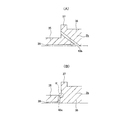
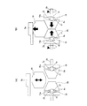
又、前記両入力軸側給油通路43a、43bのうち、入力軸2bの基端側の入力軸側給油通路43bを図8の(A)に示す様に、前記鍔部37の先端側面に開口し前記入力軸2bの軸方向に対して傾斜した状態で設けている為、この入力軸2bの小径部35の基端部に応力が集中するのを防止できる。即ち、図8の(B)に示す様に、入力軸2bの基端側の入力軸側給油通路43cを前記小径部35の基端寄り部分に、前記入力軸側潤滑油流路39から前記空間44に向けて径方向に形成した場合、前記ローディングカム装置7bが発生する押圧力の反力に基づいて、前記小径部35の基端部{図8の(B)の鎖線αで囲んだ部分}に応力が集中してしまう。又、基端側の入力軸側給油通路を、この小径部35の軸方向中間部で前記各玉16、16及び前記各カム面17、18の内径側に位置する部分に径方向に形成する事も考えられる。しかし、本例の場合、前記入力軸2bの小径部35には、前記両カム板15b、15b同士の間隔を適切な寸法に規制すると共に、前記入力軸2bから、先端側(図1〜2の左側)のカム板15bにトルクを伝達する為のカラー52を外嵌している。この為、前記小径部35の軸方向中間部に入力軸側給油通路を設けただけでは、前記各玉16、16及び前記各カム面17、18に潤滑油を十分に送り込む事ができない可能性がある。前記カラー52の基端側縁に切り欠きを設けておく事も考えられるが、前記入力軸側給油通路の形成位置と円周方向の位相を合わせるのが面倒である。前記小径部35の外周面のうち、軸方向に関して前記入力軸側給油通路を設けた位置に全周に亙って環状凹溝を設ければ、前記位相合わせの必要はなくなるが、この環状凹溝を設けた部分の強度を十分に確保できなくなる可能性がある。これに対して本例の構造によれば、この様な問題を生じる事はない。   Further, of the input shaft side oil supply passages 43a and 43b, the input shaft side oil supply passage 43b on the base end side of the input shaft 2b is opened at the front end side surface of the flange portion 37 as shown in FIG. Since the input shaft 2b is provided in an inclined state with respect to the axial direction, stress can be prevented from concentrating on the proximal end portion of the small diameter portion 35 of the input shaft 2b. That is, as shown in FIG. 8 (B), the input shaft side oil supply passage 43c on the base end side of the input shaft 2b is set closer to the base end portion of the small diameter portion 35 from the input shaft side lubricating oil flow path 39 to the above. When formed in the radial direction toward the space 44, based on the reaction force of the pressing force generated by the loading cam device 7b, the base end portion of the small-diameter portion 35 {enclosed by the chain line α in FIG. Stress concentrates on the part}. An input shaft side oil supply passage on the base end side is formed in a radial direction at a portion located on the inner diameter side of each of the balls 16, 16 and each of the cam surfaces 17, 18 at the axially intermediate portion of the small diameter portion 35. Things can also be considered. However, in the case of this example, the small-diameter portion 35 of the input shaft 2b is controlled to have an appropriate dimension between the cam plates 15b, 15b, and from the input shaft 2b to the tip side (FIGS. 1-2). A collar 52 for transmitting torque is externally fitted to the cam plate 15b on the left side. For this reason, there is a possibility that the lubricating oil cannot be sufficiently fed to the balls 16 and 16 and the cam surfaces 17 and 18 simply by providing the input shaft side oil supply passage at the intermediate portion in the axial direction of the small diameter portion 35. There is. Although it is conceivable to provide a notch in the base end side edge of the collar 52, it is troublesome to match the position where the input shaft side oil supply passage is formed and the phase in the circumferential direction. If an annular groove is provided over the entire circumference of the outer peripheral surface of the small-diameter portion 35 at a position where the input shaft-side oil supply passage is provided in the axial direction, the phase alignment is not necessary. There is a possibility that sufficient strength of the portion provided with the groove cannot be secured. On the other hand, according to the structure of this example, such a problem does not occur.

本発明の対象となる摩擦ローラ式減速機は、電気自動車の駆動系に限らず、各種回転機械装置の動力伝達装置として利用できる。
又、本発明の対象となる摩擦ローラ式減速機は、前述した図9に示す様な、遊星ローラ式の摩擦ローラ式減速機とする事もできる。
The friction roller type speed reducer which is an object of the present invention is not limited to a drive system of an electric vehicle, and can be used as a power transmission device for various rotary machine devices.
Further, the friction roller type speed reducer to which the present invention is applied can be a planetary roller type friction roller type speed reducer as shown in FIG.

1、1a、1b 摩擦ローラ式減速機
2、2a、2b 入力軸
3、3a、3b 出力軸
4、4a、4b 太陽ローラ
5、5a、5b 環状ローラ
6 遊星ローラ
7、7a、7b ローディングカム装置
8a〜8d 太陽ローラ素子
9 環状空間
10 遊星軸
11 キャリア
12 止め輪
13 支え環
14 皿ばね
15、15a、15b カム板
16 玉
17 被駆動側カム面
18 駆動側カム面
19、19a 中間ローラ
20 自転軸
21 ハウジング
22 入力側小径円筒部
23 多列玉軸受ユニット
24 出力側小径円筒部
25 複列玉軸受ユニット
26 ラビリンスシール
27 連結部
28、28a 支持フレーム
29 軸受ケース
30 出力側転がり軸受ユニット
31 出力側シーリングユニット
32 連結ブラケット
33 入力側転がり軸受ユニット
34 入力側シーリングユニット
35 小径部
36 大径部
37 鍔部
38 ローディングナット
39 入力軸側潤滑油流路
40 出力軸側潤滑油流路
41 給油口
42 ラジアルニードル軸受
43a〜43c 入力軸側給油通路
44 空間
45 カム板側給油通路
46 庇部
47 揺動フレーム
48 玉軸受
49 連結部
50 柱部
51 供給路
52 カラー
53 ノズル
54 円形凹部
1, 1a, 1b Friction roller type speed reducer 2, 2a, 2b Input shaft 3, 3a, 3b Output shaft 4, 4a, 4b Sun roller 5, 5a, 5b Annular roller 6 Planetary roller 7, 7a, 7b Loading cam device 8a -8d Sun roller element 9 Annular space 10 Planetary shaft 11 Carrier 12 Retaining ring 13 Support ring 14 Belleville spring 15, 15a, 15b Cam plate 16 Ball 17 Drive side cam surface 18 Drive side cam surface 19, 19a Intermediate roller 20 Rotating shaft DESCRIPTION OF SYMBOLS 21 Housing 22 Input side small diameter cylindrical part 23 Multi row ball bearing unit 24 Output side small diameter cylindrical part 25 Double row ball bearing unit 26 Labyrinth seal 27 Connection part 28, 28a Support frame 29 Bearing case 30 Output side rolling bearing unit 31 Output side sealing Unit 32 Connecting bracket 33 Input side rolling bearing unit 34 Input side sealing unit 35 Small diameter part 36 Large diameter part 37 collar part 38 Loading nut 39 Input shaft side lubricating oil flow path 40 Output shaft side lubricating oil flow path 41 Oil supply port 42 Radial needle bearings 43a to 43c Input shaft side oil supply path 44 Space 45 Cam plate side oil supply passage 46 Hook portion 47 Oscillating frame 48 Ball bearing 49 Connection portion 50 Column portion 51 Supply path 52 Collar 53 Nozzle 54 Circular recess

Claims (1)

入力軸と、出力軸と、太陽ローラと、環状ローラと、複数個の中間ローラと、ローディングカム装置とを備え、
このうちの太陽ローラは、軸方向に分割された1対の太陽ローラ素子を前記入力軸の周囲に、互いの先端面同士の間に隙間を介在させた状態で互いに同心に、且つ、この入力軸に対する相対回転を可能に配置して成るもので、前記両太陽ローラ素子の外周面は、それぞれの先端面に向かうに従って外径が小さくなる方向に傾斜した傾斜面であって、これら両傾斜面を転がり接触面としており、
前記環状ローラは、前記太陽ローラの周囲にこの太陽ローラと同心に配置されたもので、内周面を転がり接触面としており、
前記各中間ローラは、前記太陽ローラの外周面と前記環状ローラの内周面との間の環状空間の円周方向複数箇所に、それぞれが前記入力軸と平行に配置された自転軸を中心とする回転自在に支持された状態で、それぞれの外周面を前記太陽ローラの外周面と前記環状ローラの内周面とに転がり接触させており、
前記ローディングカム装置は、前記両太陽ローラ素子のうちの少なくとも一方の太陽ローラ素子である可動太陽ローラ素子と前記入力軸との間に設けられて、この入力軸の回転に伴ってこの可動太陽ローラ素子を相手方の太陽ローラ素子に向けて軸方向に押圧しつつ回転させるものであって、この可動太陽ローラ素子の基端面の円周方向複数箇所に設けられた被駆動側カム面と、前記入力軸の一部に固定されてこの入力軸と共に回転するカム板のうちで前記可動太陽ローラ素子の基端面に対向する片側面の円周方向複数箇所に設けられた駆動側カム面との間に転動体を挟持して成るもので、これら各駆動側カム面及び前記各被駆動側カム面はそれぞれ、軸方向に関する深さが円周方向に関して漸次変化して端部に向かうに従って浅くなる形状を有するものであり、
前記環状ローラと前記各自転軸を支持した部材とのうちの一方の部材を、前記太陽ローラを中心とする回転を阻止した状態とし、他方の部材を前記出力軸に結合して、この他方の部材によりこの出力軸を回転駆動自在とした摩擦ローラ式減速機に於いて、
前記ローディングカム装置のカム板が、前記入力軸の基端側の大径部と先端側の小径部との間の段差面に突き当てられた状態で、この入力軸に対し固定されており、これらカム板と入力軸とに前記各転動体に潤滑油を供給する為の給油通路がそれぞれ1乃至複数箇所に設けられており、この入力軸の内部に設けられた潤滑油流路を通じて、前記各給油通路に潤滑油を送り込み自在としており、前記入力軸側の給油通路が前記段差面に開口し、この入力軸の中心軸に対して傾斜した状態で設けられている事を特徴とする摩擦ローラ式減速機。
An input shaft, an output shaft, a sun roller, an annular roller, a plurality of intermediate rollers, and a loading cam device;
Of these, the sun rollers are concentric to each other with a pair of sun roller elements divided in the axial direction around the input shaft, with a gap between the tip surfaces of the elements. The outer peripheral surfaces of the two sun roller elements are inclined surfaces that are inclined in a direction in which the outer diameter decreases toward the respective front end surfaces, and these two inclined surfaces are arranged. Rolling contact surface,
The annular roller is arranged concentrically with the sun roller around the sun roller, and has an inner peripheral surface as a rolling contact surface.
Each of the intermediate rollers is centered on a rotation shaft disposed in parallel with the input shaft at a plurality of locations in the circumferential direction of the annular space between the outer peripheral surface of the sun roller and the inner peripheral surface of the annular roller. In a state of being rotatably supported, each outer peripheral surface is in rolling contact with the outer peripheral surface of the sun roller and the inner peripheral surface of the annular roller,
The loading cam device is provided between a movable sun roller element, which is at least one of the sun roller elements, and the input shaft, and the movable sun roller is rotated along with the rotation of the input shaft. The element is rotated while being pressed in the axial direction toward the other sun roller element, and the driven cam surface provided at a plurality of circumferential directions on the base end face of the movable sun roller element, and the input Of the cam plate that is fixed to a part of the shaft and rotates together with the input shaft, between the drive side cam surfaces provided at a plurality of circumferential positions on one side facing the base end surface of the movable sun roller element. Each of the driving cam surfaces and the driven cam surfaces has a shape in which the depth in the axial direction gradually changes in the circumferential direction and becomes shallower toward the end portion. Are those having,
One member of the annular roller and the member supporting each rotation shaft is in a state in which rotation around the sun roller is prevented, and the other member is coupled to the output shaft, In a friction roller type speed reducer in which the output shaft can be rotated and driven by a member,
The cam plate of the loading cam device is fixed to the input shaft in a state where the cam plate is abutted against the step surface between the large diameter portion on the proximal end side and the small diameter portion on the distal end side of the input shaft, The cam plate and the input shaft are provided with one or a plurality of oil supply passages for supplying lubricating oil to the respective rolling elements, and through the lubricating oil passages provided in the input shaft, the oil supply passages are provided. Lubricating oil can be freely fed into each oil supply passage, and the oil supply passage on the input shaft side is opened in the step surface and is provided in a state inclined with respect to the central axis of the input shaft. Roller reducer.
JP2011254642A 2011-11-22 2011-11-22 Friction roller type speed reducer Pending JP2013108572A (en)

Priority Applications (1)

Application Number Priority Date Filing Date Title
JP2011254642A JP2013108572A (en) 2011-11-22 2011-11-22 Friction roller type speed reducer

Applications Claiming Priority (1)

Application Number Priority Date Filing Date Title
JP2011254642A JP2013108572A (en) 2011-11-22 2011-11-22 Friction roller type speed reducer

Publications (2)

Publication Number Publication Date
JP2013108572A true JP2013108572A (en) 2013-06-06
JP2013108572A5 JP2013108572A5 (en) 2014-12-25

Family

ID=48705522

Family Applications (1)

Application Number Title Priority Date Filing Date
JP2011254642A Pending JP2013108572A (en) 2011-11-22 2011-11-22 Friction roller type speed reducer

Country Status (1)

Country Link
JP (1) JP2013108572A (en)

Cited By (1)

* Cited by examiner, † Cited by third party
Publication number Priority date Publication date Assignee Title
EP3279509A4 (en) * 2015-03-30 2018-05-02 NSK Ltd. Friction roller type reduction gear

Citations (2)

* Cited by examiner, † Cited by third party
Publication number Priority date Publication date Assignee Title
JPS59187154A (en) * 1983-04-06 1984-10-24 Yamaha Motor Co Ltd Planetary gear type reduction gear
JP2006002882A (en) * 2004-06-18 2006-01-05 Nsk Ltd Toroidal continuously variable transmission

Patent Citations (2)

* Cited by examiner, † Cited by third party
Publication number Priority date Publication date Assignee Title
JPS59187154A (en) * 1983-04-06 1984-10-24 Yamaha Motor Co Ltd Planetary gear type reduction gear
JP2006002882A (en) * 2004-06-18 2006-01-05 Nsk Ltd Toroidal continuously variable transmission

Cited By (3)

* Cited by examiner, † Cited by third party
Publication number Priority date Publication date Assignee Title
EP3279509A4 (en) * 2015-03-30 2018-05-02 NSK Ltd. Friction roller type reduction gear
US10359102B2 (en) 2015-03-30 2019-07-23 Nsk Ltd. Friction roller-type reduction gear
EP3889465A1 (en) * 2015-03-30 2021-10-06 NSK Ltd. Friction roller-type reduction gear

Similar Documents

Publication Publication Date Title
JPH04151053A (en) Traction type gear shifter
JP6094319B2 (en) Friction roller reducer
JP2013231448A (en) One-way clutch and power generating device
JP2013124761A (en) Rolling bearing
JP2011149481A (en) Toroidal type continuously variable transmission
JP2012207778A (en) Friction roller type reduction gear and electric vehicle driving device
US20170299024A1 (en) Loading cam device and friction roller-type speed reducer
JP5935473B2 (en) Toroidal continuously variable transmission
US20140309076A1 (en) Differential gear
JP5849645B2 (en) Friction roller reducer
JP2013108572A (en) Friction roller type speed reducer
JP2012193793A (en) Friction roller type reduction gear and electric vehicle drive unit
JP2012193792A (en) Friction roller type reduction gear and electric vehicle drive unit
WO2019098105A1 (en) Pressing device for toroidal continuously variable transmission
JP4860560B2 (en) Toroidal continuously variable transmission
JP2012197930A (en) Friction roller type reduction gear and electric vehicle drive system
JP4370892B2 (en) Planetary gear set
JP2016156389A (en) Final speed reduction device
JP6314534B2 (en) Friction roller reducer
JP5867132B2 (en) Friction roller reducer
WO2015052950A1 (en) Single-cavity toroidal continuously variable transmission
JP2012193794A (en) Friction roller type reduction gear and electric vehicle drive unit
JP2013130232A (en) Friction roller type reduction gear
JP2015227681A (en) Friction roller transmission
JP6582550B2 (en) Single cavity toroidal continuously variable transmission

Legal Events

Date Code Title Description
A521 Written amendment

Free format text: JAPANESE INTERMEDIATE CODE: A523

Effective date: 20141106

A621 Written request for application examination

Free format text: JAPANESE INTERMEDIATE CODE: A621

Effective date: 20141106

A131 Notification of reasons for refusal

Free format text: JAPANESE INTERMEDIATE CODE: A131

Effective date: 20150728

A977 Report on retrieval

Free format text: JAPANESE INTERMEDIATE CODE: A971007

Effective date: 20150730

A02 Decision of refusal

Free format text: JAPANESE INTERMEDIATE CODE: A02

Effective date: 20151124