JP2013106902A - Suspension device for top board support mechanism, x-ray computerized tomography apparatus and method for reducing deflection - Google Patents
Suspension device for top board support mechanism, x-ray computerized tomography apparatus and method for reducing deflection Download PDFInfo
- Publication number
- JP2013106902A JP2013106902A JP2011256330A JP2011256330A JP2013106902A JP 2013106902 A JP2013106902 A JP 2013106902A JP 2011256330 A JP2011256330 A JP 2011256330A JP 2011256330 A JP2011256330 A JP 2011256330A JP 2013106902 A JP2013106902 A JP 2013106902A
- Authority
- JP
- Japan
- Prior art keywords
- top plate
- support mechanism
- deflection
- amount
- plate support
- Prior art date
- Legal status (The legal status is an assumption and is not a legal conclusion. Google has not performed a legal analysis and makes no representation as to the accuracy of the status listed.)
- Pending
Links
Images

Landscapes
- Apparatus For Radiation Diagnosis (AREA)
Abstract
【課題】撮影領域における天板のたわみを低減させ、天板支持機構直下に足場を形成すること。
【解決手段】本実施形態に係る天板支持機構懸下装置は、天板を移動可能に支持する天板支持機構と、前記天板支持機構を天井から懸下する長さが可変な複数の懸下部材と、前記複数の懸架部材各々の長さを変更する複数の懸下部材駆動部と、前記天板支持機構により移動された前記天板に関するたわみ量を計測する計測部と、前記たわみ量に応じて前記複数の懸下部材の長さを個々に制御する駆動制御部と、を具備することを特徴とする。
【選択図】 図1An object of the present invention is to reduce the deflection of a top plate in an imaging region and form a scaffold directly under the top plate support mechanism.
A top plate support mechanism suspension device according to the present embodiment includes a top plate support mechanism that movably supports the top plate, and a plurality of variable lengths for hanging the top plate support mechanism from the ceiling. A suspension member, a plurality of suspension member drive units that change the length of each of the plurality of suspension members, a measurement unit that measures the amount of deflection related to the top plate moved by the top plate support mechanism, and the deflection And a drive control unit that individually controls the lengths of the plurality of suspension members according to the amount.
[Selection] Figure 1
Description
本発明の実施形態は、天板支持機構を懸下する天板支持機構懸下装置に関する。 Embodiments described herein relate generally to a top plate support mechanism suspension device that suspends a top plate support mechanism.
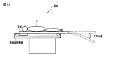
従来、X線コンピュータ断層撮影装置などの医用画像診断装置に装備される寝台は、被検体を載置する天板を片側で支える構造を採用している。被検体が載置された天板は、撮影可能位置へ水平移動により移動される。このとき、図13に示すように、天板それ自体の重み及び被検体の体重により天板が下方に変形する“たわみ”が発生する。このたわみにより、例えば、X線管等の回転軸(z軸)に沿って撮影位置を変えながらボリュームスキャンを繰り返すとき、このz軸に長く合成した全体画像において、このボリュームスキャン切り替え位置に段差が発生する問題がある。 Conventionally, a bed equipped in a medical image diagnostic apparatus such as an X-ray computed tomography apparatus employs a structure that supports a top plate on which a subject is placed on one side. The top plate on which the subject is placed is moved to a photographing position by horizontal movement. At this time, as shown in FIG. 13, “bending” occurs in which the top plate is deformed downward due to the weight of the top plate itself and the weight of the subject. Due to this deflection, for example, when the volume scan is repeated while changing the imaging position along the rotation axis (z axis) of an X-ray tube or the like, there is a step at this volume scan switching position in the entire image synthesized long on this z axis. There are problems that occur.
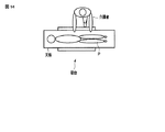
また、天板支持機構の直下に足場の設置が望まれている。ここで、足場とは、例えば、ストレッチャーに載置された被検体の天板への移動にあたって、被検体を天板に移動させる介護者の足を置く場所である。足場の設置にあたって、床に対する寝台の設置面積は、できるだけ狭くされる。また、介護者が天板スライド機構の直下を踏んでも大丈夫な構造が、採用されている。しかしながら、図14に示すように、天板支持機構の直下のスペースには、床から天板までの高さ(以下寝台の高さと呼ぶ)を可変させる機構などが内蔵されるため、上記要望を満たすための上記構造は根本的な改善ではなく、天板支持機構の直下のスペースを開放的に利用できない問題がある。 In addition, it is desired to install a scaffold directly under the top plate support mechanism. Here, the scaffold is, for example, a place where a caregiver's foot for moving the subject to the top plate is placed when the subject placed on the stretcher is moved to the top plate. In installing the scaffolding, the area of the bed for the floor is made as small as possible. In addition, a structure that allows a caregiver to step directly under the top slide mechanism is employed. However, as shown in FIG. 14, the space directly under the top plate support mechanism incorporates a mechanism for changing the height from the floor to the top plate (hereinafter referred to as the height of the bed). The above structure for filling is not a fundamental improvement, and there is a problem that the space directly under the top plate support mechanism cannot be used openly.
目的は、撮影領域における天板のたわみを低減させ、天板支持機構直下に足場を形成することにある。 The purpose is to reduce the deflection of the top plate in the imaging region and to form a scaffold directly under the top plate support mechanism.
本実施形態に係る天板支持機構懸下装置は、天板を移動可能に支持する天板支持機構と、前記天板支持機構を天井から懸下する長さが可変な複数の懸下部材と、前記複数の懸架部材各々の長さを変更する複数の懸下部材駆動部と、前記天板支持機構により移動された前記天板に関するたわみ量を計測する計測部と、前記たわみ量に応じて前記複数の懸下部材の長さを個々に制御する駆動制御部と、を具備することを特徴とする。 The top plate support mechanism suspension device according to the present embodiment includes a top plate support mechanism that movably supports the top plate, and a plurality of suspension members that are variable in length for hanging the top plate support mechanism from the ceiling. A plurality of suspension member driving units that change the length of each of the plurality of suspension members, a measurement unit that measures the amount of deflection related to the top plate moved by the top plate support mechanism, and the amount of deflection And a drive control unit that individually controls the lengths of the plurality of suspension members.
以下、X線コンピュータ断層撮影装置(Computed Tomography)の実施形態について図面を参照しながら説明する。なお、X線コンピュータ断層撮影装置には、X線管とX線検出器とが一体として被検体の周囲を回転するRotate/Rotate−Type、リング状にアレイされた多数のX線検出素子が固定され、X線管のみが被検体の周囲を回転するStationary/Rotate−Type等様々なタイプがあり、いずれのタイプでも本実施形態へ適用可能である。また、画像を再構成するには被検体の周囲一周、360°分の投影データが、またハーフスキャン法でも180°+ファン角度分の投影データが必要とされる。いずれの再構成方式に対しても本実施形態へ適用可能である。また、入射X線を電荷に変化するメカニズムは、シンチレータ等の蛍光体でX線を光に変換し更にその光をフォトダイオード等の光電変換素子で電荷に変換する間接変換形と、X線によるセレン等の半導体内での電子正孔対の生成及びその電極への移動すなわち光導電現象を利用した直接変換形とが主流である。X線検出素子としては、それらのいずれの方式を採用してもよい。さらに、近年では、X線管とX線検出器との複数のペアを回転リングに搭載したいわゆる多管球型のX線コンピュータ断層撮影装置の製品化が進み、その周辺技術の開発が進んでいる。本実施形態においては、従来からの一管球型のX線コンピュータ断層撮影装置であっても、多管球型のX線コンピュータ断層撮影装置であってもいずれも適用可能である。ここでは、一管球型として説明する。 Hereinafter, embodiments of an X-ray computed tomography apparatus (Computed Tomography) will be described with reference to the drawings. Note that in the X-ray computed tomography apparatus, an X-ray tube and an X-ray detector are integrated and a Rotate / Rotate-Type in which the periphery of the subject rotates and a large number of X-ray detection elements arrayed in a ring shape are fixed. There are various types such as Stationary / Rotate-Type in which only the X-ray tube rotates around the subject, and any type is applicable to the present embodiment. Further, in order to reconstruct an image, projection data for 360 ° around the subject and projection data for 180 ° + fan angle are required for the half scan method. The present embodiment can be applied to any reconfiguration method. In addition, the mechanism for changing incident X-rays into electric charges is based on an indirect conversion type in which X-rays are converted into light by a phosphor such as a scintillator, and the light is further converted into electric charges by a photoelectric conversion element such as a photodiode, and by X-rays. The generation of electron-hole pairs in a semiconductor such as selenium and the transfer to the electrodes, that is, the direct conversion type utilizing a photoconductive phenomenon, are the mainstream. Any of these methods may be adopted as the X-ray detection element. Furthermore, in recent years, the so-called multi-tube type X-ray computed tomography apparatus in which a plurality of pairs of X-ray tubes and X-ray detectors are mounted on a rotating ring has been commercialized, and the development of peripheral technologies has progressed. Yes. In the present embodiment, either a conventional single-tube X-ray computed tomography apparatus or a multi-tube X-ray computed tomography apparatus can be applied. Here, a single tube type will be described.
なお、以下の説明において、略同一の機能及び構成を有する構成要素については、同一符号を付し、重複説明は必要な場合にのみ行う。 In the following description, components having substantially the same function and configuration are denoted by the same reference numerals, and redundant description will be given only when necessary.
(第1の実施形態)
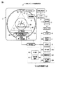
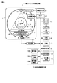
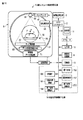
図1は、第1の実施形態に係るX線コンピュータ断層撮影装置1の構成を示す図である。
第1の実施形態に係るX線コンピュータ断層撮影装置1は、高電圧発生部3、ガントリ5、前処理部7、再構成処理部9、表示部11、記憶部13、入力部15、ホストコントローラ17、天板支持機構懸下装置19を有する。
(First embodiment)
FIG. 1 is a diagram showing a configuration of an X-ray computed tomography apparatus 1 according to the first embodiment.
The X-ray computed tomography apparatus 1 according to the first embodiment includes a high voltage generation unit 3, a
高電圧発生部3は、X線管55に供給するための高電圧を発生する。図1において、高電圧発生部3は、ガントリ5の外部に設けられている。なお、高電圧発生部3は、後述する回転フレーム51に搭載されてもよい。以下、説明の便宜上、高電圧発生部3は、ガントリ5の外部に設けられているものとする。
The high voltage generator 3 generates a high voltage to be supplied to the
ガントリ5には、回転支持機構が収容される。回転支持機構は、回転フレーム51と、回転軸Zを中心として回転自在に回転フレーム51を支持するフレーム支持機構と回転フレーム51の回転を駆動する回転駆動部53とを有する。回転フレーム51には、X線管55と、2次元アレイ型または多列型とも称されるエリア検出器57とが搭載される。エリア検出器57は、撮影領域59を挟んでX線管55に対向する。X線管55は、スリップリング61を介して、高電圧発生部3に電気的に接続される。回転駆動部53は、後述するホストコントローラ17による制御の下で、ダイレクトドライブまたはベルトドライブにより、回転フレーム51を回転させる。
The
X線管55は、スリップリング61を介して高電圧発生部3から電圧の印加および電流の供給を受けて、X線の焦点からX線を放射する。X線の焦点から放射されたX線は、X線管55のX線放射窓に取り付けられたコリメーターユニット63により、例えばコーンビーム形(角錐形)に整形される。X線の放射範囲は、点線65で示されている。X軸は、回転軸Zと直交し、放射されるX線の焦点を通る直線である。Y軸は、X軸および回転軸Zと直交する直線である。なお、説明の便宜上このXYZ座標系は、回転軸Zを中心として回転する回転座標系として説明する。
The
エリア検出器57は、回転軸Zを挟んでX線管55に対峙する位置およびアングルで取り付けられる。エリア検出器57は、複数のX線検出素子を有する。ここでは、単一のX線検出素子が単一のチャンネルを構成しているものとして説明する。複数のチャンネルは、回転軸Zに直交し、かつ放射されるX線の焦点を中心として、この中心から1チャンネル分のX線検出素子の受光部中心までの距離を半径とする円弧方向(チャンネル方向)とZ方向との2方向に関して2次元状に配列される。また、エリア検出器57は、複数のX線検出素子を1列に配列した複数のモジュールで構成されてもよい。モジュール各々は、上記チャンネル方向に沿って略円弧方向に1次元状に配列される。
The area detector 57 is attached at a position and an angle facing the
また複数のX線検出素子は、チャンネル方向とスライス方向との2方向に関して2次元状に配列させてもよい。すなわち、2次元状の配列は、上記チャンネル方向に沿って一次元状に配列された複数のチャンネルを、スライス方向に関して複数列並べて構成される。このような2次元状のX線検出素子配列を有するエリア検出器57は、略円弧方向に1次元状に配列される複数の上記モジュールをスライス方向に関して複数列並べて構成されてもよい。 The plurality of X-ray detection elements may be two-dimensionally arranged in two directions, that is, a channel direction and a slice direction. That is, the two-dimensional arrangement is configured by arranging a plurality of channels arranged in a one-dimensional manner along the channel direction in a plurality of rows in the slice direction. The area detector 57 having such a two-dimensional X-ray detection element array may be configured by arranging a plurality of the above-described modules arranged in a one-dimensional shape in a substantially arc direction in a plurality of rows in the slice direction.
撮影又はスキャンに際しては、X線管55とエリア検出器57との間の円筒形の撮影領域59内に、被検体Pが天板67に載置され挿入される。エリア検出器57の出力側には、DAS(Data Acquisition System)と呼ばれるデータ収集回路69が接続される。
During imaging or scanning, the subject P is placed on the
データ収集回路69には、エリア検出器57の各チャンネルの電流信号を電圧に変換するI−V変換器と、この電圧信号をX線の曝射周期に同期して周期的に積分する積分器と、この積分器の出力信号を増幅するアンプと、このアンプの出力信号をディジタル信号変換するアナログ・ディジタル・コンバータとが、チャンネルごとに取り付けられている。データ収集回路69から出力されるデータ(純生データ(pure raw data))は、磁気送受信又は光送受信を用いた非接触データ伝送部71を経由して、前処理部7に伝送される。
The
前処理部7は、データ収集回路69から出力される純生データに対して前処理を施す。前処理には、例えばチャンネル間の感度不均一補正処理、X線強吸収体、主に金属部による極端な信号強度の低下または、信号脱落を補正する処理等が含まれる。前処理部7から出力される再構成処理直前のデータ(生データ(raw data)または、投影データと称される、ここでは投影データという)は、データ収集したときにビューアングルを表すデータと関連付けられて、磁気ディスク、光磁気ディスク、又は半導体メモリを備えた記憶部13に記憶される。
The
なお、投影データとは、被検体を透過したX線の強度に応じたデータ値の集合である。ここでは説明の便宜上、ワンショットで略同時に収集したビューアングルが同一である全チャンネルにわたる一揃いの投影データを、投影データセットと称する。また、ビューアングルは、X線管55が回転軸Zを中心として周回する円軌道の各位置を、回転軸Zから鉛直上向きにおける円軌道の最上部を0°として360°の範囲の角度で表したものである。なお、投影データセットの各チャンネルに対する投影データは、ビューアングル、コーン角、チャンネル番号によって識別される。また、投影データセットの各チャンネルに対する投影データは、X線管55から放出されるX線のエネルギーに応じて、識別されてもよい。
The projection data is a set of data values corresponding to the intensity of X-rays that have passed through the subject. Here, for convenience of explanation, a set of projection data over all channels having the same view angle collected almost simultaneously in one shot is referred to as a projection data set. Further, the view angle represents each position of the circular orbit around which the
再構成処理部9は、ビューアングルが360°又は180°+ファン角度の範囲内の投影データセットに基づいて、フェルドカンプ法またはコーンビーム再構成法により、略円柱形の3次元画像を再構成する機能を有する。ボリュームデータにおけるスライス面に垂直な方向(Z方向)の端の領域には、撮像視野(Field of view)の領域を再構成するための360°分の投影データがそろわない領域が存在する。投影データが不足する領域は、ボリュームデータの信頼性が低い。投影データが不足する領域は、再構成しない又は再構成画像を表示しない。この領域は一般にマスク(MASK)領域と称される。フェルドカンプ法は、コーンビームのように再構成面に対して投影レイが交差する場合の再構成法である。フェルドカンプ法は、コーン角が小さいことを前提として畳み込みの際にはコーンビームをファン投影ビームとみなして再構成処理し、逆投影においてはスキャンの際のレイに沿って再構成処理する近似的画像再構成法である。コーンビーム再構成法は、フェルドカンプ法よりもコーン角のエラーが抑えられる方法として、再構成面に対するレイの角度に応じて投影データを補正する再構成法である。
The
表示部11は、再構成処理部9で再構成された医用画像、X線コンピュータ断層撮影のために設定される条件などを表示する。
The
記憶部13は、再構成処理部9で再構成された医用画像(以下再構成画像と呼ぶ)を記憶する。記憶部13は、後述する入力部15により入力された操作者の指示、画像処理の条件、撮影条件などの情報を記憶する。記憶部13は、前処理部7から出力された投影データを記憶する。記憶部13は、X線コンピュータ断層撮影のために高電圧発生部3、ガントリ5、後述する天板支持機構懸下装置19などを制御する制御プログラムを記憶する。
The storage unit 13 stores medical images reconstructed by the reconstruction processing unit 9 (hereinafter referred to as reconstructed images). The storage unit 13 stores information such as an operator's instruction, image processing conditions, and shooting conditions input by the
入力部15は、操作者が所望するX線コンピュータ断層撮影の撮影条件、所定の値などを入力する。具体的には、入力部15は、操作者からの各種指示・命令・情報・選択・設定を本X線コンピュータ断層撮影装置1に取り込む。入力部15は、図示しないが、関心領域の設定などを行うためのトラックボール、スイッチボタン、マウス、キーボード等を有する。入力部15は、表示画面上に表示されるカーソルの座標を検出し、検出した座標をホストコントローラ17に出力する。なお、入力部15は、表示画面を覆うように設けられたタッチパネルでもよい。この場合、入力部15は、電磁誘導式、電磁歪式、感圧式等の座標読み取り原理でタッチ指示された座標を検出し、検出した座標をホストコントローラ17に出力する。
The
ホストコントローラ17は、本X線コンピュータ断層撮影装置1の中枢として機能する。ホストコントローラ17は、図示しないCPUを備える。ホストコントローラ17は、記憶部13に記憶された制御プログラムに基づいて、X線コンピュータ断層撮影のために高電圧発生部3、ガントリ5、天板支持機構懸下装置19などを制御する。ホストコントローラ17は、所定の画像発生・表示等を実行するための制御プログラムを、記憶部13から読み出して自身が有するメモリ上に展開し、各種処理に関する演算・処理等を実行する。
The
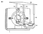
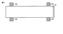
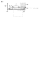
天板支持機構懸下装置19は、天板支持機構191、懸下部材193、懸下部材駆動部194、計測部195、駆動制御部197を有する。図2は、天板支持機構191と、懸下部材193と、ガントリ5との斜視図である。図3は、天板支持機構191を天井から見た上面図である。
The top plate support mechanism suspension device 19 includes a top
天板支持機構191は、図示していない天板駆動部による駆動により、被検体Pが載置された天板67を、ガントリ5の撮影領域59内へ移動させる。
The top
懸下部材193は、天板支持機構191を天井から懸下する。複数の懸架部材193各々は、天板支持機構191を天井から懸下する長さが可変な機能(以下、長さ可変機能と呼ぶ)を有する。懸下部材193は、例えば、ギアとラックとで構成される。なお、懸下部材193は、ワイヤのように天板支持機構191を天井から吊り下げる部材であってもよい。また、懸下部材193は、インナーチューブとアウターチューブとを組み合わせて液体を封入した部材であってもよい。なお、懸下部材193と天板支持機構との間には、任意の方向に回転可能な図示していない取付部を有していてもよい。
The
懸下部材駆動部194は、後述する駆動制御部197からの指示に従って、複数の懸下部材193各々の長さを変更する。具体的には、複数の懸下部材駆動部194は、複数の懸下部材193にそれぞれ対応して設けられる。例えば、懸下部材193がギアとラックとで構成される場合、懸下部材駆動部194は、このギアを駆動させるモータである。また、懸下部材193がワイヤで構成される場合、懸下部材駆動部194は、このワイヤを巻いたり緩めたりするモータである。また、懸下部材193がインナーチューブとアウターチューブとを組み合わせて液体を封入した部材である場合、懸下部材駆動部194は、懸下部材193の長さを変更するために、この封入された液体の圧力を調整する圧力調整器であってもよい。なお、懸下部材駆動部194は、緊急時等において、被検体Pの足元近傍を床に近づけるために、懸下部材193の長さを変更することも可能である。
The suspension
計測部195は、天板支持機構191により移動された天板67のたわみ量(以下、たわみ量と呼ぶ)を計測する。例えば、計測部195は、所定の位置から天板67に向けて電磁波を照射し、反射波が戻ってくるまでの時間を計測することにより、たわみ量を計測する。所定の位置とは、例えば、ガントリ5内の天板直下である。具体的には、計測部195は、例えば、電磁波送受信部を有する。電磁波送受信部は、例えば、撮影領域59に挿入される天板67の下方におけるガントリ5内に設置される。撮影領域59に天板67が挿入されると、電磁波送受信部は、天板に向けて電磁波を照射する。電磁波送受信部は、天板で反射された反射電磁波を受信する。計測部195は、電磁波の送受信における時間間隔に電磁波の速度をかけることにより、電磁波送受信部から天板までの距離を計算する。計測部195は、電磁波送受信部とスライドされる前の天板67の水平位置との距離(以下、基準距離と呼ぶ)から、計算された距離を差分することにより、天板67のたわみ量を得る。基準距離は、例えば、計測部195における図示していないメモリなどに予め記憶される。なお、電磁波送受信部は、例えばレーザー送受信部であってもよい。
The measuring
駆動制御部197は、計測部195で計測されたたわみ量に応じて、複数の懸下部材193の長さを個々に制御する。具体的には、駆動制御部197は、計測部195で計測されたたわみ量を低減させるために、たわみ量に応じて、複数の懸下部材駆動部194を個々に制御する。例えば、駆動制御部197は、たわみ量に対する天井と天板支持機構191との間隔(以下、天井天板間隔と呼ぶ)の対応表と、計測されたたわみ量とに基づいて、天井天板間隔を決定する。上記対応表は、駆動制御部197における図示していないメモリなどに予め記憶される。駆動制御部197は、複数の支持部材各々の長さを決定された天井天板間隔に変更するために、懸下部材駆動部194を制御する。
The drive control unit 197 individually controls the lengths of the plurality of
(たわみ量低減機能)
たわみ量低減機能とは、計測されたたわみ量に基づいて決定された天井天板間隔に懸下部材193の長さを変更するために懸下部材駆動部194を制御することにより、たわみ量を低減させる機能である。以下、たわみ量低減機能に関する処理(以下、たわみ量低減処理と呼ぶ)について説明する。
(Deflection reduction function)
The deflection amount reduction function is a function of controlling the suspension
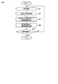
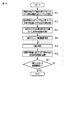
図4は、天板67のたわみ量に応じて懸下部材193の長さを変更するために懸下部材駆動部194を制御する処理の流れの一例を示す流れ図である。
FIG. 4 is a flowchart illustrating an example of a process flow for controlling the suspension
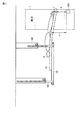
天板支持機構191を駆動させることにより、天板67がガントリ5における撮影領域59に移動される(ステップSa1)。図5は、撮影領域59に移動された天板67と、天板支持機構191と、懸下部材193との側面の一例を示す側面図である。図5に示すように、被検体Pを載置した天板67が撮影領域59に移動されると、天板67にたわみが発生する。たわみ量が、計測部195により計測される(ステップSa2)。計測されるたわみ量は、例えば、図5における点線の両端矢印aで示されている。図5における実線の両端矢印bは、電磁波送受信部1951から放射された電磁波と、天板67から反射された反射波との軌跡である。図5における実線の両端矢印cは、基準距離を示す。
By driving the top
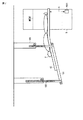
天井天板間隔が、計測されたたわみ量と対応表とに基づいて、決定される(ステップSa3)。懸下部材駆動部194により、懸下部材193の長さが、決定された天井天板間隔に変更される(ステップSa4)。図6は、第1の実施形態に係る天板支持機構191と懸下部材193との側面を示す側面図である。図6における矢印は、決定された天井天板間隔に懸下部材193の長さを変更するために、懸下部材193が伸縮される方向を示している。図7は、たわみ量を低減させるために懸下部材駆動部194を制御した後における天板支持機構191と懸下部材193との側面を示す側面図である。ステップSa4における処理により、たわみ量が低減される。
The ceiling top panel interval is determined based on the measured deflection amount and the correspondence table (step Sa3). The length of the
天板67のスライドが終了するまで、ステップSa1乃至ステップSa4における処理が繰り返される(ステップSa5)。上記繰り返しにより、例えば、非ヘリカルなX線コンピュータ断層撮影において、ボリュームスキャンごとに天板67のたわみ量が低減される。
Until the sliding of the
(変形例)
第1の実施形態との相違は、懸下部材193の長さの変更後にたわみ量を再度計測し、再度計測されたたわみ量が所定の閾値以下でない場合、懸下部材193の長さを再度変更することにある。
(Modification)
The difference from the first embodiment is that the amount of deflection is measured again after the length of the
計測部195は、懸下部材193の長さが天井天板間隔に変更された後、天板67のたわみ量を再度計測する。
After the length of the
記憶部13は、所定の閾値を記憶する。なお、所定の閾値は、駆動制御部197における図示していないメモリに記憶されてもよい。所定の閾値とは、例えば、被検体のサジタル画像において段差が表れない程度のたわみ量である。 The storage unit 13 stores a predetermined threshold value. The predetermined threshold value may be stored in a memory (not shown) in the drive control unit 197. The predetermined threshold is, for example, a deflection amount that does not cause a step in the sagittal image of the subject.
駆動制御部197は、再計測されたたわみ量と所定の閾値とを比較する。再計測されたたわみ量が所定の閾値を超える場合、駆動制御部197は、再計測されたたわみ量と対応表とに基づいて、天井天板間隔を再度決定する。駆動制御部197は、再度決定された天井天板間隔に複数の懸下部材193各々の長さを変更するために、懸下部材駆動部194を制御する。
The drive control unit 197 compares the remeasured deflection amount with a predetermined threshold value. When the remeasured deflection amount exceeds a predetermined threshold, the drive control unit 197 determines the ceiling top panel interval again based on the remeasured deflection amount and the correspondence table. The drive control unit 197 controls the suspension
(たわみ量低減機能)
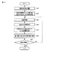
図8は、第1の実施形態の変形例に係り、天板67のたわみ量を所定の閾値以下にするために、懸下部材駆動部194を制御する処理の流れの一例を示す流れ図である。
(Deflection reduction function)
FIG. 8 is a flowchart illustrating an example of a process flow for controlling the suspension
ステップSb1乃至ステップSb4における処理は、図4におけるステップSa1乃至ステップSa4における処理と同様なため、説明を省略する。ステップSb4の処理の後、たわみ量が再計測される(ステップSb5)。再計測されたたわみ量が、所定の閾値以下であれば、ステップSb3乃至ステップSb5の処理が繰り返される。天板67の移動が終了するまで、ステップSb1乃至ステップSb6における処理が繰り返される(ステップSb7)。上記繰り返しにより、たわみ量は常に所定の閾値以下となる。例えば、ヘリカルなX線コンピュータ断層撮影については、天板67のたわみ量が計測部195によりモニタリングされることにより、たわみ量を常に所定の閾値以下にすることができる。
The processing in steps Sb1 to Sb4 is the same as the processing in steps Sa1 to Sa4 in FIG. After the process of step Sb4, the deflection amount is measured again (step Sb5). If the re-measured deflection amount is equal to or less than a predetermined threshold value, the processing from step Sb3 to step Sb5 is repeated. Until the movement of the
以上に述べた構成によれば、以下の効果を得ることができる。
本実施形態におけるX線コンピュータ断層撮影装置1によれば、長さが可変な懸下部材193により天井から天板支持機構191を懸下することで、計測された天板67のたわみ量に応じて懸下部材193の長さを変更することができる。これにより、天板67のたわみ量を減少させることができ、画像をz方向につないだとき、天板67のたわみに応じた段差が低減された全体画像を提供することができる。また、天板支持機構191の直下のスペースを開放的に利用することができる。これにより、被検体Pを天板67へ移動させる作業において介護者への身体的負担が軽減され、ストレッチャーから天板67への被検体Pの移動に関する効率が向上する。加えて、移動型フットスイッチ等は、自由に床に配置させることができる。さらに緊急時等において、懸下部材193の長さを変更することにより被検体Pの足元近傍を床に近づけることができ、被検体を緊急退避させやすくなる。
According to the configuration described above, the following effects can be obtained.
According to the X-ray computed tomography apparatus 1 in the present embodiment, the top
(第2の実施形態)
第1の実施形態との相違は、以下の通りである。まず、X線コンピュータ断層撮影前における被検体Pの透視画像またはサイノグラムに基づいて、移動された天板67の移動量に対するたわみ量を決定する。次いで、懸下部材193の長さを、決定されたたわみ量と移動量とに応じて変更することにある。
(Second Embodiment)
Differences from the first embodiment are as follows. First, based on a fluoroscopic image or sinogram of the subject P before X-ray computed tomography, a deflection amount with respect to the movement amount of the moved
図9は、第2の実施形態に係るX線コンピュータ断層撮影装置1の構成を示す図である。
画像発生部20は、前処理部7から出力された投影データに基づいて、被検体Pの透視画像またはサイノグラムを発生する。
FIG. 9 is a diagram showing a configuration of the X-ray computed tomography apparatus 1 according to the second embodiment.
The image generation unit 20 generates a fluoroscopic image or sinogram of the subject P based on the projection data output from the
たわみ量決定部199は、被検体Pの透視画像またはサイノグラムに基づいて、スライドされた天板67の移動量に対するたわみ量を決定する。移動量とは、例えば、天板支持機構191の直上に配置された天板67の位置から、天板67を移動させた後の天板67の位置までの長さである。天板67の位置とは、天板67に設けられた印であって、例えば天板67の先端である。たわみ量とは、透視画像間またはサイノグラム間における段差に対応する。
The deflection
駆動制御部197は、たわみ量決定部199で決定されたたわみ量を低減させるために、懸下部材駆動部194を制御する。具体的には、駆動制御部197は、決定されたたわみ量と対応表とに基づいて、天井天板間隔を決定する。上記対応表は、駆動制御部197における図示していないメモリなどに予め記憶される。駆動制御部197は、移動量に応じて決定された天井天板間隔に複数の懸下支持部材193各々の長さを変更するために、懸下部材駆動部194を制御する。
The drive control unit 197 controls the suspension
(たわみ量低減機能)
図10は、天板67のたわみ量に応じて懸下部材193の長さを変更するために、懸下部材駆動部194を制御する処理の流れの一例を示す流れ図である。
(Deflection reduction function)
FIG. 10 is a flowchart illustrating an example of a process flow for controlling the suspension
天板67を移動させて、X線による撮影を実行することにより、透視画像またはサイノグラムが発生される(ステップSc1)。透視画像またはサイノグラムに基づいて、天板67の移動量に対するたわみ量が決定される(ステップSc2)。決定されたたわみ量と対応表とに基づいて、天井天板間隔が移動量ごとに決定される(ステップSc3)。
A fluoroscopic image or sinogram is generated by moving the
次いで、X線コンピュータ断層撮影が開始される(ステップSc4)。この時、天板67が移動される(ステップSc5)。天板67の移動量に応じて、懸下部材駆動部194により、懸下部材193の長さが、天井天板間隔に変更される(ステップSc6)。X線コンピュータ断層撮影が終了するまで、ステップSc5とステップSc6との処理が繰り返される(ステップSc7)。
Next, X-ray computed tomography is started (step Sc4). At this time, the
以上に述べた構成によれば、以下の効果を得ることができる。
本実施形態におけるX線コンピュータ断層撮影装置1によれば、長さが可変な懸下部材193により天井から天板支持機構191を懸下することで、X線コンピュータ断層撮影前に撮影された透視画像またはサイノグラムに基づいて決定された天板67のたわみ量に応じて、懸下部材193の長さを変更することができる。これにより、X線コンピュータ断層撮影において、天板67の移動量に応じた天板67のたわみ量を減少させることができる。このことから、画像をz方向につないだとき、天板67のたわみに応じた段差が低減された全体画像を提供することができる。また、天板支持機構191の直下のスペースを開放的に利用することができる。これにより、被検体Pを天板67へ移動させる作業において介護者への身体的負担が軽減され、ストレッチャーから天板67への被検体Pの移動に関する効率が向上する。加えて、移動型フットスイッチ等は、自由に床に配置させることができる。さらに緊急時等において、被検体Pの足元近傍を床に近づけることができ、被検体Pを緊急退避させやすくなる。
According to the configuration described above, the following effects can be obtained.
According to the X-ray computed tomography apparatus 1 in the present embodiment, the fluoroscope imaged before the X-ray computed tomography is obtained by suspending the top
(第3の実施形態)
第1、第2の実施形態との相違は、天板67を撮影領域59に向けて移動させる前に、懸下部材193をガントリ5側に移動させることにより天板支持機構191をガントリ7の開口部に近づけることにある。
(Third embodiment)
The difference between the first and second embodiments is that the top
図11は、第3の実施形態に係るX線コンピュータ断層撮影装置1の構成を示す図である。
懸下部材移動部200は、懸下部材193をガントリ5側に移動させる。これにより、天板支持機構191は、ガントリ5の開口部に近接する。具体的には、懸下部材移動部200は、天井に設けられた図示していないレールと、レールから複数の懸下部材193を吊り下げる図示していないベースと、レールに沿ってベースを移動させるためにベースを駆動する図示していないベース駆動部とを有する。ホストコントローラ17からの指示に従って、ベース駆動部は、ベースを駆動させる。これにより、ベースは、レールに沿って移動する。
FIG. 11 is a diagram showing the configuration of the X-ray computed tomography apparatus 1 according to the third embodiment.
The suspension
(たわみ量低減機能)
図12は、天板67のたわみ量に応じて懸下部材193の長さを変更するために懸下部材駆動部194を制御する処理の流れの一例を示す流れ図である。
(Deflection reduction function)
FIG. 12 is a flowchart illustrating an example of a process flow for controlling the suspension
天板67に被検体Pが載置される(ステップSd1)。天板支持機構191をガントリ5の開口部に近接させるために、懸下部材193が移動される(ステップSd2)。ステップSd3乃至ステップSd7における処理は、図4のステップSa1乃至ステップSa5における処理にそれぞれ対応するため、説明を省略する。
The subject P is placed on the top 67 (step Sd1). The
以上に述べた構成によれば、以下の効果を得ることができる。
本実施形態におけるX線コンピュータ断層撮影装置1によれば、長さが可変な懸下部材193により天井から天板支持機構191を懸下することで、天板67のたわみ量に応じて、懸下部材193の長さを変更することができる。加えて、本X線コンピュータ断層撮影装置1によれば、天板67を移動させる前に懸下部材193をガントリ5側へ移動させることができる。これらにより、X線コンピュータ断層撮影において、天板67のたわみ量を減少させることができる。以上のことから、画像をz方向につないだとき、天板67のたわみに応じた段差が低減された全体画像を提供することができる。また、天板支持機構191の直下のスペースを開放的に利用することができる。これにより、被検体Pを天板67へ移動させる作業において介護者への身体的負担が軽減され、ストレッチャーから天板67への被検体Pの移動に関する効率が向上する。加えて、移動型フットスイッチ等は、自由に床に配置させることができる。さらに緊急時等において、被検体Pの足元近傍を床に近づけることができ、被検体Pを緊急退避させやすくなる。
According to the configuration described above, the following effects can be obtained.
According to the X-ray computed tomography apparatus 1 in the present embodiment, the
上記実施形態の変形例として、本X線コンピュータ断層撮影装置1における天板支持機構懸下装置19の技術的思想は、核医学診断装置、X線診断装置、核磁気共鳴装置などの他の医用画像診断装置で実現することも可能である。このとき、他の医用画像診断装置は、例えば図1、図9、図11の構成図における点線内の構成要素(天板支持機構懸下装置19)を有するものとなる。たわみ量低減機能における各処理は、第1乃至第3の実施形態と同様である。加えて、各実施形態に係る各機能は、当該処理を実行するプログラムをワークステーション等のコンピュータにインストールし、これらをメモリ上で展開することによっても実現することができる。このとき、コンピュータに当該手法を実行させることのできるプログラムは、磁気ディスク(フロッピー(登録商標)ディスク、ハードディスクなど)、光ディスク(CD−ROM、DVDなど)、半導体メモリなどの記憶媒体に格納して頒布することも可能である。 As a modification of the above embodiment, the technical idea of the top plate support mechanism suspension device 19 in the X-ray computed tomography apparatus 1 is that other medical devices such as a nuclear medicine diagnostic device, an X-ray diagnostic device, and a nuclear magnetic resonance device. It can also be realized by an image diagnostic apparatus. At this time, another medical image diagnostic apparatus has, for example, the constituent elements (top plate support mechanism suspension apparatus 19) within the dotted lines in the configuration diagrams of FIGS. Each process in the deflection amount reduction function is the same as in the first to third embodiments. In addition, each function according to each embodiment can also be realized by installing a program for executing the processing in a computer such as a workstation and developing the program on a memory. At this time, a program capable of causing the computer to execute the method is stored in a storage medium such as a magnetic disk (floppy (registered trademark) disk, hard disk, etc.), an optical disk (CD-ROM, DVD, etc.), or a semiconductor memory. It can also be distributed.
なお、本発明は上記実施形態そのままに限定されるものではなく、実施段階ではその要旨を逸脱しない範囲で構成要素を変形して具体化できる。また、上記実施形態に開示されている複数の構成要素の適宜な組み合わせにより、種々の発明を形成できる。例えば、実施形態に示される全構成要素から幾つかの構成要素を削除してもよい。さらに、異なる実施形態にわたる構成要素を適宜組み合わせてもよい。 Note that the present invention is not limited to the above-described embodiment as it is, and can be embodied by modifying the constituent elements without departing from the scope of the invention in the implementation stage. In addition, various inventions can be formed by appropriately combining a plurality of components disclosed in the embodiment. For example, some components may be deleted from all the components shown in the embodiment. Furthermore, constituent elements over different embodiments may be appropriately combined.
1…X線コンピュータ断層撮影装置、3…高電圧発生部、5…ガントリ、7…前処理部、9…再構成処理部、11…表示部、13…記憶部、15…入力部、17…ホストコントローラ、19…天板支持機構懸下装置、20…画像発生部、51…回転フレーム、53…回転駆動部、55…X線管、57…エリア検出器、59…撮影領域、61…スリップリング、63…コリメーターユニット、65…X線の放射範囲、67…天板、69…データ収集回路(DAS)、71…非接触データ伝送部、191…天板支持機構、193…懸下部材、194…懸下部材駆動部、195…計測部、197…駆動制御部、199…たわみ量決定部、200…懸下部材移動部、1951…電磁波送受信部 DESCRIPTION OF SYMBOLS 1 ... X-ray computed tomography apparatus, 3 ... High voltage generation part, 5 ... Gantry, 7 ... Pre-processing part, 9 ... Reconstruction processing part, 11 ... Display part, 13 ... Memory | storage part, 15 ... Input part, 17 ... Host controller, 19 ... Top plate support mechanism suspension device, 20 ... Image generating unit, 51 ... Rotating frame, 53 ... Rotating drive unit, 55 ... X-ray tube, 57 ... Area detector, 59 ... Imaging region, 61 ... Slip Ring, 63 ... Collimator unit, 65 ... X-ray radiation range, 67 ... Top plate, 69 ... Data acquisition circuit (DAS), 71 ... Non-contact data transmission unit, 191 ... Top plate support mechanism, 193 ... Suspension member 194: Suspension member drive unit, 195 ... Measurement unit, 197 ... Drive control unit, 199 ... Deflection amount determination unit, 200 ... Suspension member moving unit, 1951 ... Electromagnetic wave transmission / reception unit
Claims (8)
前記天板支持機構を天井から懸下する長さが可変な複数の懸下部材と、
前記複数の懸架部材各々の長さを変更する複数の懸下部材駆動部と、
前記天板支持機構により移動された前記天板に関するたわみ量を計測する計測部と、
前記たわみ量に応じて前記複数の懸下部材の長さを個々に制御する駆動制御部と、
を具備することを特徴とする天板支持機構懸下装置。 A top plate support mechanism for movably supporting the top plate;
A plurality of suspension members that are variable in length to suspend the top plate support mechanism from the ceiling;
A plurality of suspension member drive units for changing the length of each of the plurality of suspension members;
A measuring unit for measuring a deflection amount related to the top plate moved by the top plate support mechanism;
A drive control unit for individually controlling the length of the plurality of suspension members according to the amount of deflection;
A top plate support mechanism suspension device.
前記駆動制御部は、前記たわみ量を前記所定の閾値以下にするために、前記懸下部材駆動部を制御すること、
を特徴とする請求項1に記載の天板支持機構懸下装置。 A storage unit that stores a predetermined threshold value related to the amount of deflection;
The drive control unit controls the suspension member drive unit in order to make the deflection amount equal to or less than the predetermined threshold;
The top plate support mechanism suspension apparatus according to claim 1.
前記被検体が載置された天板を移動可能に支持する天板支持機構と、
前記天板支持機構を天井から懸下する長さが可変な複数の懸下部材と、
前記複数の懸架部材各々の長さを変更する複数の懸下部材駆動部と、
前記天板支持機構により移動された前記天板に関するたわみ量を計測する計測部と、
前記たわみ量に応じて前記複数の懸下部材の長さを個々に制御する駆動制御部と、
を具備することを特徴とするX線コンピュータ断層撮影装置。 A rotation support mechanism that supports an X-ray tube that generates X-rays and an X-ray detector that detects X-rays transmitted through the subject so as to be rotatable around a rotation axis;
A top plate support mechanism for movably supporting the top plate on which the subject is placed;
A plurality of suspension members that are variable in length to suspend the top plate support mechanism from the ceiling;
A plurality of suspension member drive units for changing the length of each of the plurality of suspension members;
A measuring unit for measuring a deflection amount related to the top plate moved by the top plate support mechanism;
A drive control unit for individually controlling the length of the plurality of suspension members according to the amount of deflection;
An X-ray computed tomography apparatus comprising:
前記計測部は、前記天板に関する複数回の移動ごとに前記たわみ量を計測し、
前記駆動制御部は、前記複数回の移動ごとに計測されたたわみ量に応じて前記複数の懸下部材の長さを個々に制御すること、
を特徴とする請求項3に記載のX線コンピュータ断層撮影装置。 The top plate support mechanism moves the top plate a plurality of times for non-helical X-ray computed tomography,
The measuring unit measures the amount of deflection for each of a plurality of movements related to the top plate,
The drive control unit individually controls the length of the plurality of suspension members according to the amount of deflection measured for each of the plurality of movements;
The X-ray computed tomography apparatus according to claim 3.
前記計測部は、前記所定期間にわたって前記たわみ量を計測し、
前記駆動制御部は、前記所定期間にわたって計測されたたわみ量に応じて前記複数の懸下部材の長さを個々に制御すること、
を特徴とする請求項3に記載のX線コンピュータ断層撮影装置。 The top plate support mechanism moves the top plate over a predetermined period with respect to helical X-ray computed tomography,
The measurement unit measures the deflection amount over the predetermined period,
The drive control unit individually controlling the lengths of the plurality of suspension members according to the amount of deflection measured over the predetermined period;
The X-ray computed tomography apparatus according to claim 3.
前記X線検出器からの出力に基づいて、前記被検体の透視画像またはサイノグラムを発生する画像発生部と、
前記被検体が載置された天板を移動可能に支持する天板支持機構と、
前記天板支持機構を天井から懸下する長さが可変な複数の懸下部材と、
前記複数の懸架部材各々の長さを変更する複数の懸下部材駆動部と、
前記透視画像またはサイノグラムに基づいて、前記天板の移動量に対する前記天板のたわみ量を決定するたわみ量決定部と、
前記たわみ量と前記移動量とに応じて前記複数の懸下部材の長さを個々に制御する駆動制御部と、
を具備することを特徴とするX線コンピュータ断層撮影装置。 A rotation support mechanism for rotatably supporting an X-ray tube that generates X-rays and an X-ray detector that detects X-rays transmitted through the subject;
An image generator for generating a fluoroscopic image or sinogram of the subject based on an output from the X-ray detector;
A top plate support mechanism for movably supporting the top plate on which the subject is placed;
A plurality of suspension members that are variable in length to suspend the top plate support mechanism from the ceiling;
A plurality of suspension member drive units for changing the length of each of the plurality of suspension members;
A deflection amount determining unit that determines a deflection amount of the top plate with respect to a movement amount of the top plate based on the fluoroscopic image or the sinogram;
A drive control unit for individually controlling the length of the plurality of suspension members according to the amount of deflection and the amount of movement;
An X-ray computed tomography apparatus comprising:
前記被検体が載置された天板を移動可能に支持する天板支持機構と、
前記天板支持機構を天井から懸下する長さが可変な複数の懸下部材と、
前記複数の懸架部材各々の長さを変更する複数の懸下部材駆動部と、
前記天板に被検体が載置されることを契機として、前記複数の懸下部材を、前記架台の開口まで移動させる懸下部材移動部と、
前記天板支持機構により移動された前記天板に関するたわみ量を計測する計測部と、
前記たわみ量に応じて前記複数の懸下部材の長さを個々に制御する駆動制御部と、
を具備することを特徴とするX線コンピュータ断層撮影装置。 A gantry having a rotation support mechanism that supports an X-ray tube that generates X-rays and an X-ray detector that detects X-rays transmitted through the subject so as to be rotatable about a rotation axis;
A top plate support mechanism for movably supporting the top plate on which the subject is placed;
A plurality of suspension members that are variable in length to suspend the top plate support mechanism from the ceiling;
A plurality of suspension member drive units for changing the length of each of the plurality of suspension members;
A suspension member moving unit that moves the plurality of suspension members to the opening of the gantry when the subject is placed on the top plate,
A measuring unit for measuring a deflection amount related to the top plate moved by the top plate support mechanism;
A drive control unit for individually controlling the length of the plurality of suspension members according to the amount of deflection;
An X-ray computed tomography apparatus comprising:
前記移動された天板に関するたわみ量を計測し、
前記たわみ量に応じて、前記天板を移動可能に支持する天板支持機構を天井から懸下する複数の懸架部材の長さを個々に制御すること、
を具備することを特徴とするたわみ量低減方法。 Move the top plate on which the subject is placed toward the opening of the gantry,
Measure the amount of deflection of the moved top plate,
According to the amount of deflection, individually controlling the length of a plurality of suspension members that suspend a top plate support mechanism that supports the top plate movably from the ceiling;
A deflection amount reducing method comprising:
Priority Applications (1)
| Application Number | Priority Date | Filing Date | Title |
|---|---|---|---|
| JP2011256330A JP2013106902A (en) | 2011-11-24 | 2011-11-24 | Suspension device for top board support mechanism, x-ray computerized tomography apparatus and method for reducing deflection |
Applications Claiming Priority (1)
| Application Number | Priority Date | Filing Date | Title |
|---|---|---|---|
| JP2011256330A JP2013106902A (en) | 2011-11-24 | 2011-11-24 | Suspension device for top board support mechanism, x-ray computerized tomography apparatus and method for reducing deflection |
Publications (1)
| Publication Number | Publication Date |
|---|---|
| JP2013106902A true JP2013106902A (en) | 2013-06-06 |
Family
ID=48704298
Family Applications (1)
| Application Number | Title | Priority Date | Filing Date |
|---|---|---|---|
| JP2011256330A Pending JP2013106902A (en) | 2011-11-24 | 2011-11-24 | Suspension device for top board support mechanism, x-ray computerized tomography apparatus and method for reducing deflection |
Country Status (1)
| Country | Link |
|---|---|
| JP (1) | JP2013106902A (en) |
Cited By (2)
| Publication number | Priority date | Publication date | Assignee | Title |
|---|---|---|---|---|
| CN115251966A (en) * | 2022-07-12 | 2022-11-01 | 赛诺威盛科技(北京)股份有限公司 | CT scanning table sag compensation device and CT scanning equipment |
| CN120167988A (en) * | 2025-05-22 | 2025-06-20 | 上海顺泰诺医疗设备有限公司 | A CT scanning device |
-
2011
- 2011-11-24 JP JP2011256330A patent/JP2013106902A/en active Pending
Cited By (2)
| Publication number | Priority date | Publication date | Assignee | Title |
|---|---|---|---|---|
| CN115251966A (en) * | 2022-07-12 | 2022-11-01 | 赛诺威盛科技(北京)股份有限公司 | CT scanning table sag compensation device and CT scanning equipment |
| CN120167988A (en) * | 2025-05-22 | 2025-06-20 | 上海顺泰诺医疗设备有限公司 | A CT scanning device |
Similar Documents
| Publication | Publication Date | Title |
|---|---|---|
| CN104023642B (en) | Medical diagnostic imaging apparatus bed and medical diagnostic imaging apparatus | |
| CN103889331B (en) | Medical diagnostic imaging apparatus, medical image-processing apparatus and medical image processing method | |
| US8681933B2 (en) | X-ray computed tomography apparatus | |
| JP5675257B2 (en) | Medical image processing apparatus, X-ray computed tomography apparatus, medical image processing method, and medical image processing program | |
| JP6283875B2 (en) | Medical image processing apparatus, X-ray diagnostic apparatus, and X-ray computed tomography apparatus | |
| JP6294008B2 (en) | X-ray computed tomography apparatus, reconstruction processing method, and reconstruction processing program | |
| JP6359278B2 (en) | X-ray computed tomography apparatus and medical image processing apparatus | |
| JP6425917B2 (en) | X-ray computed tomography apparatus, top control apparatus, and top control method | |
| JP2013106902A (en) | Suspension device for top board support mechanism, x-ray computerized tomography apparatus and method for reducing deflection | |
| JP6521575B2 (en) | X-ray computed tomography apparatus | |
| EP2866203A1 (en) | X-ray computed tomography apparatus, medical image processing apparatus, and medical image processing method | |
| JP5917106B2 (en) | X-ray computed tomography apparatus and brush replacement timing output method | |
| CN103458792B (en) | X-ray computed tomography apparatus and reconstruction processing method | |
| JP6449383B2 (en) | Medical image processing apparatus and X-ray diagnostic apparatus | |
| JP2014042662A (en) | X-ray computerized tomographic device and scan control program | |
| JP7224880B2 (en) | X-ray equipment | |
| JP2006068338A (en) | Radiographic equipment | |
| JP6162446B2 (en) | X-ray computed tomography apparatus and dose attenuation apparatus | |
| JP2006116174A (en) | Photographing apparatus | |
| JP2014054388A (en) | Bed for medical image diagnostic apparatus and x-ray computed tomographic apparatus | |
| JP2015144783A (en) | Medical diagnostic imaging apparatus, cell sheet, and cell sheet detection method |
Legal Events
| Date | Code | Title | Description |
|---|---|---|---|
| RD04 | Notification of resignation of power of attorney |
Free format text: JAPANESE INTERMEDIATE CODE: A7424 Effective date: 20131205 |
|
| RD04 | Notification of resignation of power of attorney |
Free format text: JAPANESE INTERMEDIATE CODE: A7424 Effective date: 20131212 |
|
| RD04 | Notification of resignation of power of attorney |
Free format text: JAPANESE INTERMEDIATE CODE: A7424 Effective date: 20131219 |
|
| RD04 | Notification of resignation of power of attorney |
Free format text: JAPANESE INTERMEDIATE CODE: A7424 Effective date: 20131226 |
|
| RD04 | Notification of resignation of power of attorney |
Free format text: JAPANESE INTERMEDIATE CODE: A7424 Effective date: 20140109 |