JP2013102720A - Harness - Google Patents
Harness Download PDFInfo
- Publication number
- JP2013102720A JP2013102720A JP2011247808A JP2011247808A JP2013102720A JP 2013102720 A JP2013102720 A JP 2013102720A JP 2011247808 A JP2011247808 A JP 2011247808A JP 2011247808 A JP2011247808 A JP 2011247808A JP 2013102720 A JP2013102720 A JP 2013102720A
- Authority
- JP
- Japan
- Prior art keywords
- pad
- operator
- harness
- waist
- belt
- Prior art date
- Legal status (The legal status is an assumption and is not a legal conclusion. Google has not performed a legal analysis and makes no representation as to the accuracy of the status listed.)
- Granted
Links
Images


Classifications
-
- A—HUMAN NECESSITIES
- A01—AGRICULTURE; FORESTRY; ANIMAL HUSBANDRY; HUNTING; TRAPPING; FISHING
- A01D—HARVESTING; MOWING
- A01D34/00—Mowers; Mowing apparatus of harvesters
- A01D34/835—Mowers; Mowing apparatus of harvesters specially adapted for particular purposes
- A01D34/90—Mowers; Mowing apparatus of harvesters specially adapted for particular purposes for carrying by the operator
- A01D34/902—Ergonomic provisions
-
- A—HUMAN NECESSITIES
- A45—HAND OR TRAVELLING ARTICLES
- A45F—TRAVELLING OR CAMP EQUIPMENT: SACKS OR PACKS CARRIED ON THE BODY
- A45F3/00—Travelling or camp articles; Sacks or packs carried on the body
- A45F3/14—Carrying-straps; Pack-carrying harnesses
-
- A—HUMAN NECESSITIES
- A45—HAND OR TRAVELLING ARTICLES
- A45F—TRAVELLING OR CAMP EQUIPMENT: SACKS OR PACKS CARRIED ON THE BODY
- A45F3/00—Travelling or camp articles; Sacks or packs carried on the body
- A45F3/14—Carrying-straps; Pack-carrying harnesses
- A45F2003/146—Pack-carrying harnesses
Landscapes
- Life Sciences & Earth Sciences (AREA)
- Environmental Sciences (AREA)
- Harvester Elements (AREA)
- Orthopedics, Nursing, And Contraception (AREA)
- Purses, Travelling Bags, Baskets, Or Suitcases (AREA)
- Portable Outdoor Equipment (AREA)
Abstract
Description
この発明は、刈払機やブロワ等の動力工具を支持するために作業者が装着するハーネスに関する。 The present invention relates to a harness worn by an operator for supporting a power tool such as a brush cutter or a blower.
刈払機やブロワ等の動力工具を用いて作業を行う場合、作業性を考慮して作業者はハーネスと称される作業具を装着して、ハーネスに動力工具を吊り下げ係止等することで、動力工具の重量を体で支持できるようにしている。このハーネスには、特許文献1に示すように、作業者の背部に配されるバックプレートと、このバックプレートに固定された肩ベルト及び側部ベルトと、側部ベルトの下方に配置され調整バンドを介して側部ベルトに固定される骨盤ベルトとを備え、肩ベルトを作業者の肩部に配すると共に側部ベルトを作業者の左側で体に当接させた上で、バンドを用いて骨盤ベルトを作業者の腰部に密着させるものが知られている。
When working with a power tool such as a brush cutter or blower, the operator must wear a work tool called a harness in consideration of workability and suspend and lock the power tool on the harness. The weight of the power tool can be supported by the body. In this harness, as shown in
また特許文献2に示すように、バックプレートと、このバックプレートに固定された腰ベルトと、一端がバックプレートに固定されて、他端に腰ベルトに取り付けたバンドが係止された肩ベルトと、一端がバックプレートの左右にそれぞれ固定されて作業者の体の左右に当接させる第1及び第2側部ベルトと、一端がバックプレートに固定されると共に中間部に第2側部ベルトの他端部が固定されて、刈払機等を係止する支持部材を支持する支持ベルトとを備えたハーネスも知られている。このハーネスでは、肩ベルトを作業者の肩部に配し、各側部ベルトを作業者の側筋部に当接させて、第1側部ベルトの他端に取りけたバックルの雄部材と、支持ベルトの他端に取り付けた雌部材とを、作業者の前側で係合させるようにしている。
Also, as shown in
しかしながら特許文献1に記載のハーネスでは、動力工具の重量の大部分を、作業者の体の左側に位置する側部ベルトと、骨盤ベルトとで負担することになる。このため、作業者の体の左側と腰に荷重が集中することになって、作業者の体にかかる負担が大きくなることが懸案されていた。また特許文献2に記載のハーネスでは、第1及び第2の側部ベルトを用いることで、動力工具の重量が作業者の体の片側に集中することを回避できるものの、肩ベルトと腰ベルトとはバンドで繋がっているだけであった。したがって、動力工具の重量を、肩ベルトと腰ベルトに分散できる構造であるとは言い難く、結果として作業者にかかる負担も十分に軽減できているとは言い難かった。
However, in the harness described in
この発明は、このような状況に鑑み提案されたものであって、作業者にかかる負担をより軽減できるハーネスを提供することを目的とする。 This invention is proposed in view of such a situation, and it aims at providing the harness which can reduce the burden concerning an operator more.
請求項1の発明に係るハーネスは、動力工具を支持するために作業者が装着して、前記作業者の両肩部に着脱可能に保持される一対の肩掛けパッドと、前記作業者の腰部に着脱可能に保持される腰当てパッドと、を有するハーネスであって、前記一対の前記肩掛けパッドと前記腰当てパッドとを、前記作業者の前側の一箇所で着脱可能な着脱部材を備えることを特徴とする。
A harness according to the invention of
請求項2の発明は、請求項1において、前記腰当てパッドは左右方向に延設されており、前記腰当てパッドは、前記着脱部材を介して前記肩掛けパッドと前記腰当てパッドとを連結した位置よりも、前記ハーネスの上下方向で下方に配置されることを特徴とする。 According to a second aspect of the present invention, in the first aspect, the waist pad extends in the left-right direction, and the waist pad connects the shoulder pad and the waist pad via the detachable member. It arrange | positions below in the up-down direction of the said harness rather than a position.
請求項3の発明は、請求項2において、前記腰当てパッドの最下部に、水平部分を設けたことを特徴とする。
The invention of
請求項4の発明は、請求項2において、前記腰当てパッドの前記左右方向の中心部に、該腰当てパッドの最下部を設けたことを特徴とする。 According to a fourth aspect of the present invention, in the second aspect, the lowermost portion of the waist pad is provided at a central portion in the left-right direction of the waist pad.
請求項5の発明は、請求項1ないし4のいずれかにおいて、前記作業者が前記ハーネスを装着した状態で、前記作業者の脇腹に当接する脇当てパッドを備えることを特徴とする。 According to a fifth aspect of the present invention, in any one of the first to fourth aspects, the worker has a side pad that contacts the flank of the worker in a state where the worker wears the harness.
請求項6の発明は、請求項5において、前記脇当てパッドを前記脇腹に締め付け可能な締め付けベルトを備え、前記締め付けベルトは、前記着脱部材に挿通保持されて、前記肩掛けパッドに、長さ調整可能に取り付けられていることを特徴とする。
The invention of
請求項1の発明に係るハーネスによれば、動力工具の重量を、着脱部材を介して連結された一対の肩掛けパッドと腰当てパッドとに分散させる結果、作業者にかかる負担を軽減できる。
さらに着脱部材を用いることにより、作業者の前側の一箇所で、一対の肩掛けパッドと腰当てパッドとを着脱可能にしたため、一対の肩掛けパッドと腰当てパッドとの着脱操作が容易になる。その結果作業者は、簡単にハーネスを着脱することができる。
請求項2の発明によれば、着脱部材を介して、肩掛けパッドと腰当てパッドとを連結したときは、腰当てパッドが、作業者の腰回りに密着しながら作業者の前側に向けて斜め上方へ傾斜した姿勢を保つことが可能になる。したがって、腰当てパッドは作業者の腰部から下がり難くなる。
請求項3の発明によれば、作業者がハーネスを装着したときに、腰当てパッドの最下部が、水平部分によって作業者の腰に密着し易くなる。
さらに、腰当てパッドの水平部分を地面に接触させた状態で、腰当てパッドを安定した姿勢で地面に置くことができる。加えて腰当てパッドを地面に置いたときは、前記水平部分に土等が付着するだけで、腰当てパッドの下面全体に土等が付着することがない。よって、前記下面全体が汚れることを防止できる。
請求項4の発明によれば、作業者がハーネスを装着したときに、腰当てパッドの最下部に当たる腰当てパッドの左右方向の中心部が、作業者の腰部に密着し易い状態を作り出すことができる。
請求項5の発明によれば、動力工具の重量を脇当てパッドにも分散させて、作業者にかかる負担をより軽減できる。
請求項6の発明によれば、締め付けベルトの長さを調整することで、肩掛けパッドを作業者の肩部に接近する方向へ引き締める動作と、脇当てパッドを作業者の脇腹に締め付ける動作とを同時に行うことが可能になる。
According to the harness according to the first aspect of the present invention, the weight of the power tool is distributed to the pair of shoulder pads and the waist pad connected via the detachable member, so that the burden on the operator can be reduced.
Further, by using the detachable member, the pair of shoulder pads and the waist pad can be attached and detached at one place on the front side of the operator, so that the pair of shoulder pads and the waist pad can be easily attached and detached. As a result, the worker can easily attach and detach the harness.
According to the second aspect of the present invention, when the shoulder pad and the waist pad are connected via the attaching / detaching member, the waist pad is inclined toward the front side of the operator while closely contacting the waist of the worker. It becomes possible to maintain a posture inclined upward. Therefore, it is difficult for the waist pad to descend from the operator's waist.
According to the invention of
Furthermore, the waist pad can be placed on the ground in a stable posture with the horizontal portion of the waist pad in contact with the ground. In addition, when the waist pad is placed on the ground, only soil or the like adheres to the horizontal portion, and soil or the like does not adhere to the entire lower surface of the waist pad. Therefore, it can prevent that the said whole lower surface gets dirty.
According to the invention of
According to the invention of
According to the invention of
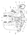
本発明の実施形態を図1ないし図7を参照しつつ説明する。図1に示すハーネス1は、刈払機等の動力工具を支持するために作業者が装着するもので、バックプレート2と、肩掛けパッド3、3と、腰当てパッド4と、肩掛けベルト5、5と、第1ベルト長さ調整具6、6と、バックル7と、脇当てパッド8と、支持部材9と、引掛けリング10とを備えている。
An embodiment of the present invention will be described with reference to FIGS. A
図2及び図3に示すように作業者がハーネス1を装着したときは、バックプレート2は作業者の背部に配置される。このバックプレート2は、上下方向に延びる板状であって合成樹脂製で可撓性を有する。バックプレート2には、左右の上端から上方へ突出してバックプレート2の下方よりも幅寸法が小さい幅狭部12(図1及び図2参照。)が一対形成されている。さらに図1及び図2に示すようにバックプレート2の上方には、作業者の指が挿入可能な大きさで手提げ可能な穴13が開設されている。この穴13は、ハーネス1の上下方向(図1の上下方向)で、肩掛けパッド3、3がハーネス1に固定された位置P1(図1参照。)よりも上方に配置されている。作業者は、穴13に挿入した指でバックプレート2を保持した状態で、ハーネス1を手に提げて持ち運ぶことができる。
When the worker wears the
図2ないし図4に示すように作業者がハーネス1を装着したときは、肩掛けパッド3、3は作業者の両肩部に当接する。各肩掛けパッド3の上方は、バックプレート2の内表面に異なる位置で固定されている。その結果図1及び図4に示すように、肩掛けパッド3、3は、バックプレート2から分岐するように該バックプレート2に固定されている。図1及び図5に示すように肩掛けパッド3は、合成繊維製の生地14の内部に、緩衝部材としてのポリエチレンフォーム15とポリウレタンフォーム16とを内在させた帯状とされている。加えて本実施形態では、例えば活性炭等の消臭剤が封入された短冊状の消臭シート17が、ポリエチレンフォーム15とポリウレタンフォーム16との間に挟持されている。この消臭シート17によって、肩掛けパッド3、3には防臭機能が付与される。なお消臭シート17は本発明の防臭シートの一例である。
As shown in FIGS. 2 to 4, when the worker wears the
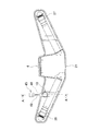
図2及び図3に示すように作業者がハーネス1を装着したときは、腰当てパッド4は作業者の腰回りに当接する。腰当てパッド4は、バックプレート2の下方の外表面に固定されている。この腰当てパッド4は、肩掛けパッド3と同様に合成繊維製の生地の内部にポリエチレンフォームとポリウレタンフォームとを内材させて、左右方向に延びる帯状とされている。図1及び図6に示すように腰当てパッド4は、左右方向の中心部の下面に水平部分21を設けて、この水平部分21を最下部として左方及び右方に向けて斜め上方へ傾斜した形状とされている。なお図1及び図6では、左右方向を腰当てパッド4の左右方向とした。
When the worker wears the
図3及び図4に示すように作業者がハーネス1を装着したときは、一対の肩掛けベルト5、5は、それぞれ肩掛けパッド3の上側で作業者の肩部に掛けられる。各肩掛けベルト5の下方は肩掛けパッド3に縫い付けられている。一方、肩掛けベルト5の上方は、調整部材としての第1ベルト長さ調整具6に移動可能に係止されて、肩掛けベルト5の長さは第1ベルト長さ調整具6で調整可能とされている。図2及び図3に示すように、この第1ベルト長さ調整具6は、バックプレート2の幅狭部12に接続されたベルト22に取り付けられている。
As shown in FIGS. 3 and 4, when the worker wears the
図1及び図4に示すように、各肩掛けベルト5の下端には第2ベルト長さ調整具23が取り付けられている。そして、一方の第2ベルト長さ調整具23には、バックル7の雄部材24に接続されて雄部材24の位置を調整可能な位置調整ベルト25が移動可能に係止されている。さらに雄部材24には、ベルトを挿入保持するスリットを設けた合成樹脂製の第1プレート26が固定されている。また図1、4、6に示すように腰当てパッド4には、第3ベルト長さ調整具27が取り付けられている。そして、第1プレート位置調整ベルト28は、第1プレート26のスリットに挿通保持された状態で、第3ベルト長さ調整具27によって長さ調整可能とされている。
As shown in FIGS. 1 and 4, a second
図2ないし図4に示すように作業者がハーネス1を装着したときは、脇当てパッド8を作業者の左脇腹に当接させることができる。なお以下では、図2の左側を作業者の左側、右側を作業者の右側とし、図4の左側を作業者の右側、右側を作業者の左側とする。また図1に示すように脇当てパッド8の上側には、締め付けベルト31の一部が縫い付けられており、この締め付けベルト31はバックル7の雌部材32のスリットに挿通保持されている。図1及び図2に示すように、締め付けベルト31の一方はバックプレート2に固定され、締め付けベルト31の他方は、他方の第2ベルト長さ調整具23に移動可能に係止されている。この第2ベルト長さ調整具23によって締め付けベルト31の長さを調整可能とすることで、脇当てパッド8が作業者の左脇腹へ近づく方向へ移動可能となる。
When the worker wears the
さらに上記の雌部材32(図1参照。)にも、第1プレート26(同図参照。)と同様の第2プレート33が固定されている。加えて第2プレート位置調整ベルト34(図1及び図4参照。)が、第2プレート32のスリットに挿通保持された状態で、腰当てパッド4に取り付けた第4ベルト長さ調整具35(図1参照。)によって長さ調整可能とされている。
Further, a
図1、2、4に示すように支持部材9は、合成樹脂で形成された上下方向に延びる板状であって、作業者の右横で刈払機36(図4参照。)を係止するために用いられる。この支持部材9は、刈払機36のフック(図示せず。)を係止する係止金具37と、係止金具37に係止したフックの抜け止めを行うストッパ38とを備えている。支持部材9に設けたスリットには、支持部材位置調整ベルト39が挿通保持されて、支持部材位置調整ベルト39の一方はバックプレート2(図2参照。)に取り付けられて、他方は、雄部材24に接続されたベルト41に取り付けた第5ベルト長さ調整具42(図4参照。)に移動可能に係止されている。なお、作業者の右横は本発明の作業者の他方の横側の一例である。
As shown in FIGS. 1, 2, and 4, the
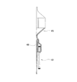
また図1及び図2に示すようにバックプレート2には、作業者の左横で腰当てパッド4を支持する支持ベルト45が取り付けられている。支持ベルト4の上方は、バックプレート2に接続されたベルト46に取り付けた第6ベルト長さ調整具47に移動可能に係止されている。一方図6及び図7に示すように、支持ベルト45の下方は、腰当てパッド4の左右方向の中心部よりも左側に縫い付けられて、腰当てパッド4にループ部48を形成する。支持ベルト45の上下方向の一部では、支持ベルト45の幅方向の両端部を幅方向の中心側へ折り返して重ね合わせた部分(重ね合わせ部49)が縫い付けられている。これにより図1及び図6に示すように、支持ベルト45は重ね合わせ部49で細くなることで動き易くなる。
As shown in FIGS. 1 and 2, a
図6及び図7に示すようにループ部48には、金属製の引掛けリング10が取り付けられている。図2に示すように作業者がハーネス1を装着すると、引掛けリング10は作業者の左横に位置する。この引掛けリング10は、物品を引っ掛け可能なものである。一例として、図示しない燃料を入れた缶のホルダにカラビナを取り付けた上で、このカラビナを引掛けリング10に引っ掛けることで、作業者は簡単に燃料を入れた缶を持ち歩くことができる。なお、引掛けリング10は本発明の引掛部の一例であり、作業者の左横は本発明の作業者の一方の横側の一例である。
As shown in FIGS. 6 and 7, a
次に、作業者がハーネス1を装着して草刈り作業を行う場合を説明する。以下では図1の左側をハーネス1の左側、図1の右側をハーネス1の右側として説明する。作業者は、図1に示すバックプレート2を背部に配置した状態で肩掛けパッド3、3を後方から両肩部に当接させるために、左腕を左側の肩掛けパッド3と脇当てパッド8との間、右腕を右側の肩掛けパッド3と腰当てパッド4との間にそれぞれ挿入する。その後、腰当てパッド4を後方から作業者の腰部に巻きながら、作業者の前側でバックル7の雄部材24をバックル7の雌部材32に差し込んで連結する。すると、図4に示すように各プレート26、33が作業者の前側に当接した状態になる。図4に示した状態では、肩掛けパッド3、3は、ハーネス1の上方から下方へ対角線状に延びて、作業者の前側でバックル7と両ベルト25、31とを用いて互いに接続可能である。さらに図示するように支持部材9は、支持部材位置調整ベルト39によって、肩掛けパッド3、3の接続部となるバックル7に繋いだ状態になる。
Next, a case where the worker performs the mowing work while wearing the
加えて図4に示した状態では、バックル7と両ベルト25、31、両プレート位置調整ベルト28、34を用いることで、肩掛けパッド3、3と腰当てパッド4とを作業者の前側の一箇所で連結可能としている。さらに図3から理解できるように腰当てパッド4は、肩掛けパッド3、3と腰当てパッド4とを連結した位置Pよりも、ハーネス1の上下方向で下方に配置されている。その結果図2及び図3に示すように、腰当てパッド4が、作業者の腰回りに密着しながら作業者の前側に向けて斜め上方へ傾斜した状態を保つことが可能になる。これにより刈払機36を用いた草刈り作業中に、力が支持部材9に加わっても、腰当てパッド4は作業者の腰部から下がり難くなる。図2に示すように、腰当てパッド4の水平部分21によって腰当てパッド4の最下部が作業者の腰部に密着し易くなる。これに加えて本実施形態の腰当てパッド4では、左右方向の中心部に最下部となる水平部分21を設けたことで、腰当てパッド4の前記中心部が作業者の腰部に密着し易くなる。なお、バックル7と両ベルト25、31、両プレート位置調整ベルト28、34は、本発明の着脱部材の一例である。
In addition, in the state shown in FIG. 4, by using the
また本実施形態では図4に示すように脇当てパッド8の締め付けベルト31が、左側の肩掛けパッド3の肩掛けベルト5に取り付けた第2ベルト長さ調整具23に移動可能に係止されており、締め付けベルト31を引っ張ると、左側の肩掛けパッド3は作業者の左肩部に接近する方向へ引き締められると共に、脇当てパッド8は作業者の左脇腹を締め付ける方向へ移動する。なお、左側の肩掛けパッド3は、本発明の一対の肩掛けパッドの少なくとも一方の一例であり、作業者の左肩部は、本発明の両肩部の少なくとも一方の一例である。
In this embodiment, as shown in FIG. 4, the
さらに肩掛けベルト5、5を、ベルト22、22を介してバックプレート2の幅狭部12、12に取り付けられた第1ベルト長さ調整具6、6(図3及び図4参照。)から引き出すように引っ張って、幅狭部12、12を作業者の背部側へ引き寄せると、バックプレート2の位置を前記背部側へ引き寄せるように調整できる。特に幅狭部12、12は、バックプレート2の下方よりも断面二次モーメントが小さいため、幅狭部12、12を設けたバックプレート2の上方が、バックプレート2の下方よりもたわみ易くなって前記背部側へ引き寄せられ易くなる。加えてバックプレート2に穴13を開設したことで、バックプレート2では、位置P1(図1参照。)よりも上方の剛性が位置P1よりも下方の剛性に比べて低下する。よって、前記上方が前記下方に比べてたわみ易くなる。これらのことから図3に示すように作業者がハーネス1を装着したときに、バックプレート2を作業者の背部に沿って湾曲させて密着させることができる。なお、肩掛けベルト5、5及びベルト22、22は本発明のベルトの一例である。
Further, the
作業者は上記の要領でハーネス1を装着した後に、刈払機36(図4参照。)のフックを支持部材9の係止金具37(図4参照。)に係止すると、刈払機36の重量がハーネス1を介して作業者に加わることになる。このときバックプレート2を作業者の背部に密着させたことで、刈払機36の重量をバックプレート2全体に分散できる。さらには、肩掛けパッド3、3と腰当てパッド4とを作業者の前側の一箇所で連結したことで、刈払機36の重量を、連結した肩掛けパッド3、3と腰当てパッド4とに分散可能となる。この他にも、支持部材9を一対の肩掛けパッド3、3の接続部となるバックル7に繋いだことで、刈払機36の重量を、肩掛けパッド3、3が当接する作業者の両肩部に分散可能となる。その上刈払機36の重量を、作業者の左脇腹に当接する脇当てパッド8にも分散可能となる。これらの結果、作業者の体にかかる負担を軽減できる。
When the operator attaches the
作業者は、ハーネス1によって刈払機36を安定して支持して左右に振りながら刈刃で草を刈る。草刈り作業時に作業者がかいた汗は肩掛けパッド3、3に吸収される。この場合でも肩掛けパッド3、3に収容した消臭シート17で、汗の臭いを除去できる。そこでハーネス1を複数の作業者で共用する場合でも、他人の汗に起因する不快な臭いを気にすることなく作業者は快適にハーネス1を使用できる。
The operator stably supports the
また図2に示すように本実施形態のハーネス1では草刈り作業時に、作業者の右横で刈払機36を支持部材9に係止したままで、作業者の左横で、例えば燃料を入れた缶のホルダをカラビナを介して引掛けリング10に引っ掛けることができる。引掛けリング10を取り付けた腰当てパッド4は、支持ベルト45によってバックプレート2に支持されているため、引掛けリング10に引っ掛けた燃料を入れた缶等の重量で、腰当てパッド4が作業者の腰部から下がることを防止できる。そして支持ベルト45は、重ね合わせ部49(図1及び図6参照。)で細くなることで動き易くなるため、燃料を入れた缶等の重量が支持ベルト45の一部に集中することを回避できる。よって、支持ベルト45が腰当てパッド4からちぎれることを防止できる。
Further, as shown in FIG. 2, in the
<本実施形態の効果>
本実施形態のハーネス1では、肩掛けパッド3、3に防臭機能を付与したことで、肩掛けパッド3、3に吸収された作業者の汗に起因する不快な臭いを除去することが可能になる。このため、臭いを気にすることなく作業者は快適にハーネスを使用できる。
<Effect of this embodiment>
In the
また、ハーネス1における作業者の鼻に近い部分である肩掛けパッド3、3が防臭機能を有することで、肩掛けパッド3、3から不快な臭いが発せられることを軽減して、最適な防臭機能が得られる。
In addition, the
さらに消臭シート17を用いるだけで、簡単にハーネス1に対して防臭機能を持たせることができる。
Furthermore, the
加えて消臭シート17は折り曲げたりする等が簡単で取り扱いが容易になることから、消臭シート17を肩掛けパッド3、3内に収容することが容易になる。
In addition, since the
本実施形態のハーネス1では、第1ベルト長さ調整具6、6を用い、肩掛けベルト5、5の長さを調整して、バックプレート2を作業者の背部へ引き寄せる簡単な構造で、バックプレート2を作業者の背部に密着させることができる。これにより、刈払機36の重量をバックプレート2に分散させる結果、作業者にかかる負担を軽減できる。
In the
また、支持部材9を一対の肩掛けパッド3、3の接続部となるバックル7に繋いだことで、刈払機36の重量を、肩掛けパッド3、3を介して作業者の両肩部に分散可能となる。よって、作業者の一方の肩部に荷重が集中することがなくなって、作業者の肩部にかかる負担を軽減できる。
In addition, the weight of the
さらにバックプレート2の上方に設けた幅狭部12、12は、バックプレート2の下方よりも断面二次モーメントが小さくなるため、バックプレート2の上方が下方よりもたわみ易くなる。よって、第1ベルト長さ調整具6、6を用いて肩掛けベルト5、5の長さを調整することで、バックプレート2の上方を作業者の背部へ引き寄せ易くなる。
Further, the
加えてバックプレート2では、肩掛けパッド3、3が固定された位置P1よりも上方の剛性が位置P1よりも下方の剛性に比べて低下する。よって、前記上方が前記下方に比べてたわみ易くなる。さらに加えて、バックプレート2に開設した穴13に挿入した指で、バックプレート2を保持した状態で、作業者はハーネス1を手に提げて持ち運ぶことが可能になる。したがって、穴13を、ハーネス1を持ち運ぶために利用できる。
In addition, in the
本実施形態のハーネス1では、バックル7と両ベルト25、31、両プレート位置調整ベルト28、34を用いて、作業者の前側の一箇所で肩掛けパッド3、3と腰当てパッド4とを連結したため、刈払機36の重量を、連結した肩掛けパッド3、3と腰当てパッド4とに分散可能となる。その結果、作業者にかかる負担を軽減できる。さらに、バックル7の雌部材32にバックル7の雄部材24を差し込んだり、雌部材32から雄部材24を外すことにより、作業者の前側の一箇所で、肩掛けパッド3、3と腰当てパッド4とを着脱可能にした。このため、肩掛けパッド3、3と腰当てパッド4との着脱操作が容易になる。その結果作業者は、簡単にハーネス1を着脱できる。
In the
また、バックル7と両ベルト25、31、両プレート位置調整ベルト28、34を介して、肩掛けパッド3、3と腰当てパッド4とを連結したときは、腰当てパッド4が、作業者の腰回りに密着しながら作業者の前側に向けて斜め上方へ傾斜した状態を保つことが可能になる。したがって、腰当てパッド4は作業者の腰部から下がり難くなる。
Further, when the
さらに腰当てパッド4の最下部に水平部分21を設けたため、作業者がハーネス1を装着したときに、腰当てパッド4の最下部が、水平部分21によって作業者の腰部に密着し易くなる。また、水平部分21を地面に接触させた状態で、腰当てパッド4を安定した姿勢で地面に置くことができる。その上、腰当てパッド4を地面に置いたときは、水平部分21に土等が付着するだけで、腰当てパッド4の下面全体に土等が付着することがない。よって、前記下面全体が汚れることを防止できる。
Further, since the
加えて腰当てパッド4の左右方向の中心部の下面に、最下部となる水平部分21を設けたため、作業者がハーネス1を装着したときに、最下部となる腰当てパッド4の前記中心部が、作業者の腰部に密着し易い状態を作り出すことができる。
In addition, since the lowermost
さらに加えて、作業者がハーネス1を装着した状態で、刈払機36の重量を脇当てパッド8にも分散させて、作業者にかかる負担をより軽減できる。
In addition, the weight of the
これに加えて、締め付けベルト31を引っ張って該ベルト31の長さを調整することにより、作業者の左側の肩掛けパッド3を、作業者の左肩部に接近する方向へ引き締め可能にしたため、左側の肩掛けパッド3を左肩部に接近する方向へ引き締める動作と、脇当てパッド8を左脇腹に締め付ける動作とを同時に行うことが可能になる。加えて刈払機36の重量を、左側の肩掛けパッド3と脇当てパッド8とに分散できる。
In addition to this, by adjusting the length of the
本実施形態のハーネス1では、腰当てパッド4の引掛けリング10に、燃料を入れた缶等の物品を引っ掛けるだけで、物品を簡単に持ち歩くことができる。
In the
また作業者は、右横で刈払機36を支持部材9に係止した状態で、左横に位置する引掛けリング10に、物品を引っ掛けることができる。したがって、刈払機36を用いた草刈り作業を邪魔することなく、物品を持ち運ぶことができる。
In addition, the operator can hook the article on the
さらに支持ベルト45によって、腰当てパッド4をバックプレート2に支持し、引掛けリング10に引っ掛けた物品の重量で、腰当てパッド4が作業者の腰部から下がることを防止できる。
Further, the
加えて支持ベルト45は、重ね合わせ部49で細くなることで動き易くなるため、物品の重量が支持ベルト45の一部に集中することを回避できる。よって、支持ベルト45が腰当てパッド4からちぎれることを防止できる。
In addition, since the
本発明は、上述した実施形態に限定されるものではなく、発明の趣旨を逸脱しない範囲内において構成の一部を適宜変更して実施できる。例えば肩掛けパット3、3に加えて腰当てパッド4や脇当てパッド8にも、消臭シート17を収容してもよい。一方、消臭シート17に代えて、芳香成分を含浸等した芳香シートを肩掛けパッドに収容し、肩掛けパッドから放たれる芳香で防臭機能を発揮させてもよい。また消臭シートや芳香シートに代えて、粒状の消臭剤や芳香剤を肩掛けパッドに収容してもよい。
The present invention is not limited to the above-described embodiment, and can be implemented by appropriately changing a part of the configuration without departing from the spirit of the invention. For example, the
さらに上述した実施形態とは異なり、腰当てパッド4の下面であって左右方向の中心部から左又は右へずれた位置に、水平部分を設けてもよい。また上述した実施形態とは異なり腰当てパッド4を、前記中心部の下面を頂部として下面が左方及び右方に向けて斜め上方へ傾斜する形状にしてもよい。加えて上述した実施形態ではハーネスに、作業者の左脇腹に当接させる脇当てパッドを設けたが、これとは異なりハーネスに、右脇腹に当接させる脇当てパッドを設けたり、左右の脇腹にそれぞれ当接させる複数の脇当てパッドを設けてもよい。また上述した実施形態では、脇当てパッド8の上側に、締め付けベルト31の一部を縫い付けた例を示したが、これとは異なり、締め付けベルトを脇当てパッド8に挿通保持させて、この締め付けベルトの長さを調整することに伴って、脇当てパッド8を作業者の左脇腹に当接させるようにしてもよい。この場合には、脇当てパッド8の上側に、締め付けベルトの一部を縫い付けた例とは異なり、締め付けベルトが、脇当てパッド8に係止されながら、脇当てパッド8に対して抜き差し可能となることで、締め付けベルトの長さを調整するために該締め付けベルトを引っ張る力が低減可能になる。
Further, unlike the above-described embodiment, a horizontal portion may be provided on the lower surface of the
その他にも上述した実施形態とは異なり例えば、引掛けリング10に代えて面状ファスナやスナップボタンを腰当てパッド4に取り付けて、この面ファスナに、物品の面ファスナを圧着したり、前記スナップボタンに、物品のスナップボタンを止めるようにしてもよい。
Other than the above-described embodiment, for example, instead of the
1・・ハーネス、2・・バックプレート、3・・肩掛けパッド、4・・腰当てパッド、5・・肩掛けベルト、6・・第1ベルト長さ調整具、7・・バックル、8・・脇当てパッド、9・・支持部材、10・・引掛けリング、12・・幅狭部、13・・穴、15・・ポリエチレンフォーム、16・・ポリウレタンフォーム、17・・消臭シート、21・・腰当てパッドの水平部分、22・・ベルト、25・・位置調整ベルト、28・・第1プレート位置調整ベルト、31・・締め付けベルト、34・・第2プレート位置調整ベルト、36・・刈払機、45・・支持ベルト、49・・支持ベルトの重ね合わせ部、P・・肩掛けパッドと腰当てパッドとの連結位置、P1・・一対の肩掛けパッドがハーネスに固定された位置。 1 .... Harness, 2 .... Back plate, 3 .... Shoulder pad, 4 .... Lumbar pad, 5 .... Shoulder belt, 6 .... First belt length adjuster, 7 .... Buckle, 8 .... Side Contact pad, 9 ... Support member, 10 ... Hook ring, 12 ... Narrow part, 13 ... Hole, 15 ... Polyethylene foam, 16 ... Polyurethane foam, 17 ... Deodorant sheet, 21 ... Horizontal part of waist pad, 22 .... belt, 25 ... position adjustment belt, 28 ... first plate position adjustment belt, 31 ... tightening belt, 34 ... second plate position adjustment belt, 36 ... brush cutter , 45 .. Support belt, 49 .. Overlapping portion of support belt, P .. Connection position of shoulder pad and waist pad, P1 .. Position where a pair of shoulder pads are fixed to the harness.
Claims (6)
前記一対の前記肩掛けパッドと前記腰当てパッドとを、前記作業者の前側の一箇所で着脱可能な着脱部材を備えることを特徴とするハーネス。 A pair of shoulder pads that are worn by an operator to support the power tool and are detachably held on both shoulders of the operator; and a waist pad that is detachably held on the waist of the operator; A harness having
A harness comprising: a detachable member capable of detaching the pair of shoulder pads and the waist pad at one place on the front side of the operator.
前記腰当てパッドは、前記着脱部材を介して前記肩掛けパッドと前記腰当てパッドとを連結した位置よりも、前記ハーネスの上下方向で下方に配置されることを特徴とする請求項1に記載のハーネス。 The waist pad extends in the left-right direction,
The said waist pad is arrange | positioned below in the up-down direction of the said harness rather than the position which connected the said shoulder pad and the said waist pad via the said attachment / detachment member. Harness.
前記締め付けベルトは、前記着脱部材に挿通保持されて、前記肩掛けパッドに、長さ調整可能に取り付けられていることを特徴とする請求項5に記載のハーネス。 A tightening belt capable of tightening the armpit pad to the flank,
The harness according to claim 5, wherein the fastening belt is inserted and held in the detachable member and is attached to the shoulder pad so as to be adjustable in length.
Priority Applications (5)
| Application Number | Priority Date | Filing Date | Title |
|---|---|---|---|
| JP2011247808A JP5788768B2 (en) | 2011-11-11 | 2011-11-11 | Harness |
| RU2012145674/13A RU2012145674A (en) | 2011-11-11 | 2012-10-25 | EQUIPMENT |
| US13/667,584 US20130119100A1 (en) | 2011-11-11 | 2012-11-02 | Harness |
| EP12007532.0A EP2594125B1 (en) | 2011-11-11 | 2012-11-06 | Harness |
| CN201210448546.4A CN103099341B (en) | 2011-11-11 | 2012-11-09 | Harness |
Applications Claiming Priority (1)
| Application Number | Priority Date | Filing Date | Title |
|---|---|---|---|
| JP2011247808A JP5788768B2 (en) | 2011-11-11 | 2011-11-11 | Harness |
Publications (2)
| Publication Number | Publication Date |
|---|---|
| JP2013102720A true JP2013102720A (en) | 2013-05-30 |
| JP5788768B2 JP5788768B2 (en) | 2015-10-07 |
Family
ID=47227409
Family Applications (1)
| Application Number | Title | Priority Date | Filing Date |
|---|---|---|---|
| JP2011247808A Active JP5788768B2 (en) | 2011-11-11 | 2011-11-11 | Harness |
Country Status (5)
| Country | Link |
|---|---|
| US (1) | US20130119100A1 (en) |
| EP (1) | EP2594125B1 (en) |
| JP (1) | JP5788768B2 (en) |
| CN (1) | CN103099341B (en) |
| RU (1) | RU2012145674A (en) |
Families Citing this family (18)
| Publication number | Priority date | Publication date | Assignee | Title |
|---|---|---|---|---|
| JP6250978B2 (en) * | 2013-08-21 | 2017-12-20 | 株式会社やまびこ | Shoulder harness for portable work machines |
| US9808074B2 (en) | 2014-02-21 | 2017-11-07 | L.F. Centennial Ltd. | Air gun holster pouch and method of using the same |
| US9844257B2 (en) | 2014-02-21 | 2017-12-19 | L.F. Centennial Ltd. | Clip-on air gun holster |
| USD779818S1 (en) | 2015-02-23 | 2017-02-28 | L.F. Centennial Ltd. | Drill holster pouch |
| USD779196S1 (en) | 2015-02-23 | 2017-02-21 | L.F. Centennial Ltd. | Three pocket framer pouch |
| USD771937S1 (en) | 2015-02-23 | 2016-11-22 | L.F. Centennial Ltd. | Triple snap pouch |
| USD771938S1 (en) | 2015-02-23 | 2016-11-22 | L.F. Centennial Ltd. | Two pocket small framer pouch |
| USD779194S1 (en) | 2015-02-23 | 2017-02-21 | L.F. Centennial Ltd. | Hand tool pouch |
| USD771939S1 (en) | 2015-02-23 | 2016-11-22 | L.F. Centennial Ltd. | Full apron tool belt |
| USD779195S1 (en) | 2015-02-23 | 2017-02-21 | L.F. Centennial Ltd. | Two pocket framer pouch |
| USD773818S1 (en) | 2015-02-23 | 2016-12-13 | L.F. Centennial Ltd. | Backing for tool pouch |
| DE102017008754A1 (en) | 2017-09-15 | 2019-03-21 | Andreas Stihl Ag & Co. Kg | Carrying device for carrying a hand-held implement by a user |
| US11246397B2 (en) | 2018-08-23 | 2022-02-15 | Phuong Nguyen | Harness for golf bag |
| EP3685655B1 (en) * | 2018-11-30 | 2022-01-19 | Honda Motor Co., Ltd. | Work machine pad |
| WO2020110303A1 (en) * | 2018-11-30 | 2020-06-04 | 本田技研工業株式会社 | Support structure for work machine pad |
| EP3679782B1 (en) * | 2018-11-30 | 2021-06-23 | Honda Motor Co., Ltd. | Support belt for work tool |
| CN110367625B (en) * | 2019-06-12 | 2021-04-02 | 美盛文化创意股份有限公司 | Dustproof collet that role play dress was used |
| WO2024079174A1 (en) * | 2022-10-12 | 2024-04-18 | Husqvarna Ab | Tool carrying harness and strap assembly for adjusting the same |
Citations (6)
| Publication number | Priority date | Publication date | Assignee | Title |
|---|---|---|---|---|
| JPS51127429U (en) * | 1975-04-11 | 1976-10-15 | ||
| JPS5520842U (en) * | 1978-07-31 | 1980-02-09 | ||
| JPS5923925U (en) * | 1982-08-04 | 1984-02-14 | 小松ゼノア株式会社 | brush cutter shoulder band |
| US6247624B1 (en) * | 1998-06-03 | 2001-06-19 | Aktiebolaget Electrolux | Carrier device for a power-driven work tool |
| US20030121942A1 (en) * | 2001-12-28 | 2003-07-03 | I-Teh Chang | Shoulder-borne carrying straps, carrying strap assemblies and golf bags incorporating the same |
| JP2005143453A (en) * | 2003-11-19 | 2005-06-09 | Komatsu Zenoah Co | Tool for supporting portable work machine |
Family Cites Families (17)
| Publication number | Priority date | Publication date | Assignee | Title |
|---|---|---|---|---|
| US2553275A (en) * | 1948-02-23 | 1951-05-15 | Quilter John Raymond Cuthbert | Parachute harness |
| US4298149A (en) * | 1978-01-17 | 1981-11-03 | Panavision, Incorporated | Body harness for cinematographer |
| JPH0198930A (en) | 1987-10-12 | 1989-04-17 | Yokogawa Electric Corp | Radiation thermometer replaced with equivalent black body |
| US5131576A (en) * | 1990-09-17 | 1992-07-21 | Kent Turnipseed | Backpack support device |
| SE500322C2 (en) * | 1992-10-29 | 1994-06-06 | Panth Produkter Ab | Device for cleaning saw harness |
| DE19634670C2 (en) * | 1996-08-28 | 1998-12-03 | Stihl Maschf Andreas | Belt arrangement for carrying a hand-held implement |
| US6283350B1 (en) * | 2000-03-07 | 2001-09-04 | Mario Gottmeier | Backpack |
| SE519076C2 (en) * | 2001-05-31 | 2003-01-07 | Electrolux Ab | Device by a hand harness for hand tools |
| USD503276S1 (en) * | 2003-10-16 | 2005-03-29 | Aktiebolaget Electrolux | Harness for portable tools |
| DE102005001843B4 (en) * | 2005-01-14 | 2020-12-17 | Andreas Stihl Ag & Co. Kg | Carrying system for an implement and method for pruning trees |
| CN2922963Y (en) * | 2006-06-02 | 2007-07-18 | 谭复兴 | Structure-improved golf ball-bag braces |
| EP2152119B1 (en) * | 2007-06-01 | 2015-08-05 | Husqvarna AB | Harness and chest plate therein |
| EP2155014A4 (en) * | 2007-06-01 | 2015-05-27 | Husqvarna Ab | Harness for power tool having a pole |
| CN201337080Y (en) * | 2008-12-19 | 2009-11-04 | 中山百诺精密工业有限公司 | Backpacking structure of camera bag |
| ATE539601T1 (en) * | 2009-04-24 | 2012-01-15 | Makita Corp | BELT SYSTEM FOR PORTABLE DRIVE DEVICE |
| USD641975S1 (en) * | 2010-03-04 | 2011-07-26 | Andreas Stihl Ag & Co. Kg | Shoulder belt forestry advance |
| USD641155S1 (en) * | 2010-03-04 | 2011-07-12 | Andreas Stihl Ag & Co. Kg | Shoulder belt universal advance |
-
2011
- 2011-11-11 JP JP2011247808A patent/JP5788768B2/en active Active
-
2012
- 2012-10-25 RU RU2012145674/13A patent/RU2012145674A/en not_active Application Discontinuation
- 2012-11-02 US US13/667,584 patent/US20130119100A1/en not_active Abandoned
- 2012-11-06 EP EP12007532.0A patent/EP2594125B1/en active Active
- 2012-11-09 CN CN201210448546.4A patent/CN103099341B/en active Active
Patent Citations (6)
| Publication number | Priority date | Publication date | Assignee | Title |
|---|---|---|---|---|
| JPS51127429U (en) * | 1975-04-11 | 1976-10-15 | ||
| JPS5520842U (en) * | 1978-07-31 | 1980-02-09 | ||
| JPS5923925U (en) * | 1982-08-04 | 1984-02-14 | 小松ゼノア株式会社 | brush cutter shoulder band |
| US6247624B1 (en) * | 1998-06-03 | 2001-06-19 | Aktiebolaget Electrolux | Carrier device for a power-driven work tool |
| US20030121942A1 (en) * | 2001-12-28 | 2003-07-03 | I-Teh Chang | Shoulder-borne carrying straps, carrying strap assemblies and golf bags incorporating the same |
| JP2005143453A (en) * | 2003-11-19 | 2005-06-09 | Komatsu Zenoah Co | Tool for supporting portable work machine |
Non-Patent Citations (1)
| Title |
|---|
| "日工タナカ 肩掛けベルト ラークベルト", AMAZON, JPN6015007668, 20 February 2015 (2015-02-20), ISSN: 0003016563 * |
Also Published As
| Publication number | Publication date |
|---|---|
| RU2012145674A (en) | 2014-04-27 |
| CN103099341B (en) | 2014-12-10 |
| US20130119100A1 (en) | 2013-05-16 |
| CN103099341A (en) | 2013-05-15 |
| EP2594125A1 (en) | 2013-05-22 |
| EP2594125B1 (en) | 2015-01-21 |
| JP5788768B2 (en) | 2015-10-07 |
Similar Documents
| Publication | Publication Date | Title |
|---|---|---|
| JP5788768B2 (en) | Harness | |
| JP5722750B2 (en) | Harness | |
| US4467945A (en) | Baby carrier | |
| JP5792579B2 (en) | Harness type safety belt | |
| US8418897B1 (en) | Body worn child carrier | |
| US20140231472A1 (en) | Strap-on child carrier with support seating element | |
| US8523028B1 (en) | Body worn child carrier | |
| US20170065066A1 (en) | Tool retaining apparatus | |
| US20130009445A1 (en) | Traction apparatus for use with seats | |
| CN111601528B (en) | Working chair | |
| US8584622B2 (en) | Safety belt for riding double on two-wheeled vehicle | |
| JP7388823B2 (en) | Clothes, safety belts and garments themselves | |
| JP2005131146A (en) | Baby carrier | |
| JP2013102721A (en) | Harness | |
| JP3211093U (en) | Harness type safety belt work belt | |
| JP2013102718A (en) | Harness | |
| KR101445301B1 (en) | Cervical vertebral supporting apparatus for working | |
| JP2022034433A (en) | Pad for harness type safety belt | |
| KR200473921Y1 (en) | Carrier for baby | |
| JP2004275581A (en) | Full-body harness | |
| WO2007089718B1 (en) | Urine collection suspension and safety system | |
| JP6465267B2 (en) | Horizontal baby carrier | |
| JP5467902B2 (en) | Lullaby | |
| WO2009126086A1 (en) | Belt | |
| JP3077509U (en) | Safety belt for fall prevention |
Legal Events
| Date | Code | Title | Description |
|---|---|---|---|
| A621 | Written request for application examination |
Free format text: JAPANESE INTERMEDIATE CODE: A621 Effective date: 20140526 |
|
| A977 | Report on retrieval |
Free format text: JAPANESE INTERMEDIATE CODE: A971007 Effective date: 20150205 |
|
| A131 | Notification of reasons for refusal |
Free format text: JAPANESE INTERMEDIATE CODE: A131 Effective date: 20150303 |
|
| A521 | Request for written amendment filed |
Free format text: JAPANESE INTERMEDIATE CODE: A523 Effective date: 20150313 |
|
| TRDD | Decision of grant or rejection written | ||
| A01 | Written decision to grant a patent or to grant a registration (utility model) |
Free format text: JAPANESE INTERMEDIATE CODE: A01 Effective date: 20150707 |
|
| A61 | First payment of annual fees (during grant procedure) |
Free format text: JAPANESE INTERMEDIATE CODE: A61 Effective date: 20150730 |
|
| R150 | Certificate of patent or registration of utility model |
Ref document number: 5788768 Country of ref document: JP Free format text: JAPANESE INTERMEDIATE CODE: R150 |
|
| R250 | Receipt of annual fees |
Free format text: JAPANESE INTERMEDIATE CODE: R250 |
|
| R250 | Receipt of annual fees |
Free format text: JAPANESE INTERMEDIATE CODE: R250 |
|
| R250 | Receipt of annual fees |
Free format text: JAPANESE INTERMEDIATE CODE: R250 |
|
| R250 | Receipt of annual fees |
Free format text: JAPANESE INTERMEDIATE CODE: R250 |
|
| R250 | Receipt of annual fees |
Free format text: JAPANESE INTERMEDIATE CODE: R250 |
|
| R250 | Receipt of annual fees |
Free format text: JAPANESE INTERMEDIATE CODE: R250 |