JP2013094792A - Current control method in detecting constriction in consumable electrode arc welding - Google Patents
Current control method in detecting constriction in consumable electrode arc welding Download PDFInfo
- Publication number
- JP2013094792A JP2013094792A JP2011237481A JP2011237481A JP2013094792A JP 2013094792 A JP2013094792 A JP 2013094792A JP 2011237481 A JP2011237481 A JP 2011237481A JP 2011237481 A JP2011237481 A JP 2011237481A JP 2013094792 A JP2013094792 A JP 2013094792A
- Authority
- JP
- Japan
- Prior art keywords
- welding
- speed
- current
- arc
- value
- Prior art date
- Legal status (The legal status is an assumption and is not a legal conclusion. Google has not performed a legal analysis and makes no representation as to the accuracy of the status listed.)
- Granted
Links
- 238000003466 welding Methods 0.000 title claims abstract description 181
- 238000000034 method Methods 0.000 title claims abstract description 23
- 238000001514 detection method Methods 0.000 claims abstract description 47
- 239000000463 material Substances 0.000 claims description 17
- 239000002243 precursor Substances 0.000 claims description 3
- 230000001172 regenerating effect Effects 0.000 abstract 1
- 230000008929 regeneration Effects 0.000 abstract 1
- 238000011069 regeneration method Methods 0.000 abstract 1
- 230000003321 amplification Effects 0.000 description 12
- 238000003199 nucleic acid amplification method Methods 0.000 description 12
- 238000010586 diagram Methods 0.000 description 10
- 230000007423 decrease Effects 0.000 description 7
- CURLTUGMZLYLDI-UHFFFAOYSA-N Carbon dioxide Chemical compound O=C=O CURLTUGMZLYLDI-UHFFFAOYSA-N 0.000 description 6
- 230000000694 effects Effects 0.000 description 4
- 230000000630 rising effect Effects 0.000 description 4
- 239000011324 bead Substances 0.000 description 3
- 229910002092 carbon dioxide Inorganic materials 0.000 description 3
- 239000001569 carbon dioxide Substances 0.000 description 3
- 239000007921 spray Substances 0.000 description 3
- 238000002474 experimental method Methods 0.000 description 2
- 229910000831 Steel Inorganic materials 0.000 description 1
- 230000002411 adverse Effects 0.000 description 1
- 239000010953 base metal Substances 0.000 description 1
- 239000003990 capacitor Substances 0.000 description 1
- 238000006243 chemical reaction Methods 0.000 description 1
- 238000007796 conventional method Methods 0.000 description 1
- 230000007547 defect Effects 0.000 description 1
- 238000009499 grossing Methods 0.000 description 1
- 239000010959 steel Substances 0.000 description 1
- 230000007704 transition Effects 0.000 description 1
Images


Abstract
Description
本発明は、短絡期間中に溶滴のくびれを検出してアーク再発生直前に溶接電流を減少させてスパッタの発生を低減する消耗電極アーク溶接のくびれ検出時電流制御方法に関するものである。 The present invention relates to a current control method for detecting the constriction of consumable electrode arc welding that detects the constriction of droplets during a short circuit and reduces the welding current immediately before the reoccurrence of arc to reduce the generation of spatter.
図4は、短絡期間Tsとアーク期間Taとを繰り返す消耗電極アーク溶接における電流・電圧波形図及び溶滴移行図である。同図(A)は消耗電極(以下、溶接ワイヤ1という)を通電する溶接電流Iwの時間変化を示し、同図(B)は溶接ワイヤ1と母材2との間に印加する溶接電圧Vwの時間変化を示し、同図(C)〜(E)は溶滴1aの移行の様子を示す。以下、同図を参照して説明する。
FIG. 4 is a current / voltage waveform diagram and a droplet transfer diagram in consumable electrode arc welding in which the short-circuit period Ts and the arc period Ta are repeated. FIG. 4A shows the change over time of the welding current Iw for energizing the consumable electrode (hereinafter referred to as welding wire 1), and FIG. 4B shows the welding voltage Vw applied between the
時刻t1〜t3の短絡期間Ts中は溶接ワイヤ1先端の溶滴1aが母材2と短絡した状態にあり、同図(A)に示すように、溶接電流Iwは次第に増加し、同図(B)に示すように、溶接電圧Vwは短絡状態にあるために数V程度の低い値となる。また、同図(C)に示すように、時刻t1において溶滴1aが母材2と接触して短絡状態に入る。その後、同図(D)に示すように、溶滴1aを通電する溶接電流Iwによる電磁的ピンチ力によって溶滴1a上部にくびれ1bが発生する。そしてこのくびれ1bが急速に進行して、時刻t3において同図(E)に示すように、溶滴1aは溶接ワイヤ1から溶融池2aへと離脱しアーク3が再発生する。
During the short-circuit period Ts from time t1 to t3, the droplet 1a at the tip of the
溶滴1aにくびれ1bが発生すると、数百μs程度の短い時間後に短絡が開放されてアーク3が再発生する。すなわち、このくびれ1bは短絡開放の前兆現象となる。くびれ1bが発生すると、溶接電流Iwの通電路がくびれ部分で狭くなるために、くびれ部分の抵抗値が増大する。この抵抗値の増大は、くびれ1bが進行してくびれ部分がより狭くなるほど大きくなる。したがって、短絡期間Ts中において溶接ワイヤ1・母材2間の抵抗値の変化を検出することでくびれ1bの発生を検出することができる。この抵抗値の変化は、溶接電圧Vwを溶接電流Iwで除算することによって算出することができる。また、くびれ発生期間中の溶接電流Iwの変化は、溶接電圧Vwの変化に比べて小さい。このために、抵抗値の変化に代えて溶接電圧Vwの変化によってもくびれ1bの発生を検出することができる。具体的なくびれ検出方法としては、短絡期間Ts中の抵抗値又は溶接電圧値Vwの変化率(微分値)を算出し、この変化率がそれに対応する予め定めたくびれ検出基準値に達したことを判別することによってくびれ検出を行う。また、第2の方法としては、同図(B)に示すように、短絡期間Ts中のくびれ発生前の安定した短絡電圧値Vsからの電圧上昇値ΔVを算出し、時刻t2においてこの電圧上昇値ΔVが予め定めたくびれ検出基準値Vtnに達したことを判別することによってくびれ検出を行う。以下の説明では、くびれ検出方法がこの第2の方法の場合について説明するが、第1の方法、その他の方法であっても良い。時刻t3のアーク再発生の検出は、溶接電圧Vwがアーク判別値Vta以上になったことを判別して簡単に行うことができる。すなわち、Vw<Vtaの期間が短絡期間Tsとなり、Vw≧Vtaの期間がアーク期間Taとなる。時刻t2〜t3のくびれ発生を検出してからアーク再発生までの期間を、以下くびれ検出期間Tnと呼ぶことにする。
When the constriction 1b is generated in the droplet 1a, the short circuit is opened after a short time of about several hundred μs, and the
次に、時刻t3においてアークが再発生すると、同図(A)に示すように、溶接電流Iwは次第に減少し、同図(B)に示すように、溶接電圧Vwは数十V程度のアーク電圧値に変化する。このアーク期間Ta中は、アーク熱等によって溶接ワイヤ1の先端を溶融して溶滴1aを形成すると共に、母材2を溶融する。一般的に、消耗電極アーク溶接には、定電圧特性の溶接電源が使用される。短絡を伴う消耗電極アーク溶接では、溶接電流平均値(送給速度)が低いときには溶滴移行形態は短絡移行形態となり、高いときはグロビュール移行形態又はスプレー移行形態となる。
Next, when the arc is regenerated at time t3, the welding current Iw gradually decreases as shown in FIG. 5A, and the welding voltage Vw is about several tens of volts arc as shown in FIG. Changes to voltage value. During the arc period Ta, the tip of the
短絡を伴う消耗電極アーク溶接では、時刻t3においてアーク3が再発生したときの電流値Iaが大きいときは、アーク3から溶融池2aへの圧力(アーク力)が非常に大きくなり、大量のスパッタが発生する。すなわち、アーク再発生時の溶接電流値Iaに略比例してスパッタ発生量が増加する。したがって、スパッタの発生を抑制するためには、アーク再発生時の溶接電流値Iaを小さくする必要がある。このための方法として、上記のくびれの発生を検出して溶接電流Iwを減少させてアーク再発生時の溶接電流値Iaを小さくするくびれ検出時電流制御方法が従来から種々提案されている。以下、これら従来技術について説明する。
In consumable electrode arc welding with a short circuit, when the current value Ia when the
図5は、従来技術のくびれ検出時電流制御方法を搭載した溶接電源のブロック図である。以下、同図を参照して各ブロックについて説明する。 FIG. 5 is a block diagram of a welding power source equipped with a current control method for squeezing detection according to the prior art. Hereinafter, each block will be described with reference to FIG.
電源主回路PMは、3相200V等の商用電源(図示は省略)を入力として、後述する誤差増幅信号Eaに従ってインバータ制御等の出力制御を行い、出力電圧Vo及び溶接電流Iwを出力する。この電源主回路PMは、図示は省略するが、商用電源を整流する1次整流回路、整流された直流を平滑するコンデンサ、平滑された直流を高周波交流に変換するインバータ回路、高周波交流をアーク溶接に適した電圧値に降圧する変圧器、降圧された高周波交流を整流する2次整流回路、整流された直流を平滑するリアクトル、上記の誤差増幅信号Eaに基づいてインバータ回路をPWM変調制御する変調回路、を備えている。トランジスタTR及び抵抗器Rの並列回路は通電路に挿入されて、後述するように、くびれ検出時にトランジスタTRがオフ状態になり抵抗器Rを通って通電することによって溶接電流Iwを急減させる。溶接ワイヤ1は送給モータWMに結合された送給ロール5の回転によって溶接トーチ4内を送給されて、母材2との間にアーク3が発生する。溶接ワイヤ1と母材2との間には溶接電圧Vwが印加し、溶接電流Iwが通電する。
The power supply main circuit PM receives a commercial power supply (not shown) such as three-phase 200V as input, performs output control such as inverter control according to an error amplification signal Ea described later, and outputs an output voltage Vo and a welding current Iw. The power supply main circuit PM is not shown, but a primary rectifier circuit that rectifies commercial power, a capacitor that smoothes the rectified direct current, an inverter circuit that converts the smoothed direct current into high frequency alternating current, and arc welding of the high frequency alternating current A transformer for stepping down the voltage to a voltage suitable for the above, a secondary rectifying circuit for rectifying the stepped down high frequency alternating current, a reactor for smoothing the rectified direct current, and a modulation for controlling the PWM modulation of the inverter circuit based on the error amplification signal Ea. Circuit. The parallel circuit of the transistor TR and the resistor R is inserted into the energization path, and as will be described later, when the constriction is detected, the transistor TR is turned off and energized through the resistor R to rapidly reduce the welding current Iw. The
くびれ検出回路NDは、溶接電圧Vwを入力として、上述したくびれ検出方法によってくびれを検出しくびれ検出期間Tn中Lowレベルになるくびれ検出信号Ndを出力する。駆動回路DRは、このくびれ検出信号NdがLowレベルのときにのみトランジスタTRをオフ状態にする駆動信号Drを出力する。すなわち、くびれ検出期間Tn中は抵抗器Rが通電路に挿入されるために通電路抵抗値が十倍以上となり、溶接電流Iwは急減する。くびれ検出期間Tn以外の期間中はトランジスタTRはオン状態になるために、抵抗器Rは短絡されて通常の溶接電源と同一の構成となる。 The squeezing detection circuit ND receives the welding voltage Vw and detects a squeezing by the above-described squeezing detection method, and outputs a squeezing detection signal Nd that is at a low level during the squeezing detection period Tn. The drive circuit DR outputs a drive signal Dr that turns off the transistor TR only when the squeezing detection signal Nd is at a low level. That is, during the squeezing detection period Tn, the resistor R is inserted into the energization path, so that the energization path resistance value becomes ten times or more and the welding current Iw rapidly decreases. Since the transistor TR is in an on state during a period other than the constriction detection period Tn, the resistor R is short-circuited to have the same configuration as that of a normal welding power source.
遅延期間設定回路TDRは、予め定めた遅延期間設定信号Tdrを出力する。上昇期間設定回路TURは、予め定めた上昇期間設定信号Turを出力する。低くびれ電流設定回路IMRは、予め定めた低くびれ電流設定信号Imrを出力する。高アーク電流設定回路IHRは、予め定めた高アーク電流設定信号Ihrを出力する。くびれ検出時電流制御回路NICは、上記の各設定信号Tdr、Tur、Imr、Ihr及び上記のくびれ検出信号Ndを入力として、図6で後述する電源特性切換信号Sw及び電流設定信号Irを出力する。 The delay period setting circuit TDR outputs a predetermined delay period setting signal Tdr. The rising period setting circuit TUR outputs a predetermined rising period setting signal Tur. The low current setting circuit IMR outputs a predetermined low current setting signal Imr. The high arc current setting circuit IHR outputs a predetermined high arc current setting signal Ihr. The squeezing detection current control circuit NIC receives the setting signals Tdr, Tur, Imr, Ihr and the squeezing detection signal Nd, and outputs a power supply characteristic switching signal Sw and a current setting signal Ir, which will be described later with reference to FIG. .
電圧設定回路VRは、予め定めた電圧設定信号Vrを出力する。電流検出回路IDは、溶接電流Iwを検出して、電流検出信号Idを出力する。電圧検出回路VDは、出力電圧Voを検出して、電圧検出信号Vdを出力する。電圧誤差増幅回路EVは、上記の電圧設定信号Vrと上記の電圧検出信号Vdとの誤差を増幅して、電圧誤差増幅信号Evを出力する。電流誤差増幅回路EIは、上記の電流設定信号Irと上記の電流検出信号Idとの誤差を増幅して、電流誤差増幅信号Eiを出力する。電源特性切換回路SWは、上記の電源特性切換信号Swを入力として、図6で後述するくびれ検出期間Tn+遅延期間Td+上昇期間Tu中はb側に切り換わり上記の電流誤差増幅信号Eiを誤差増幅信号Eaとして出力し、それ以外の期間中はa側に切り換わり上記の電圧誤差増幅信号Evを誤差増幅信号Eaとして出力する。したがって、a側に切り換わっている期間は定電流特性期間となり、b側に切り換わっている期間は定電圧特性期間となる。 The voltage setting circuit VR outputs a predetermined voltage setting signal Vr. The current detection circuit ID detects the welding current Iw and outputs a current detection signal Id. The voltage detection circuit VD detects the output voltage Vo and outputs a voltage detection signal Vd. The voltage error amplification circuit EV amplifies an error between the voltage setting signal Vr and the voltage detection signal Vd, and outputs a voltage error amplification signal Ev. The current error amplification circuit EI amplifies an error between the current setting signal Ir and the current detection signal Id, and outputs a current error amplification signal Ei. The power supply characteristic switching circuit SW receives the power supply characteristic switching signal Sw as an input, and switches to the b side during the squeezing detection period Tn + delay period Td + rise period Tu described later with reference to FIG. 6 and error-amplifies the current error amplification signal Ei. The signal Ea is output, and during the other periods, the voltage is switched to the a side and the voltage error amplified signal Ev is output as the error amplified signal Ea. Therefore, the period switched to the a side is a constant current characteristic period, and the period switched to the b side is a constant voltage characteristic period.
送給速度設定回路FRは、予め定めた送給速度設定信号Frを出力する。送給制御回路FCは、この送給速度設定信号Frを入力として、この値に相当する送給速度で溶接ワイヤ1を送給するための送給制御信号Fcを上記の送給モータWMに出力する。
The feeding speed setting circuit FR outputs a predetermined feeding speed setting signal Fr. The feed control circuit FC inputs the feed speed setting signal Fr and outputs a feed control signal Fc for feeding the
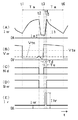
図6は、上述した溶接電源における各信号のタイミングチャートである。同図(A)は溶接電流Iwの、同図(B)は溶接電圧Vwの、同図(C)はくびれ検出信号Ndの、同図(D)は電源特性切換信号Swの、同図(E)は電流設定信号Irの時間変化を示す。以下、同図を参照して説明する。 FIG. 6 is a timing chart of each signal in the above-described welding power source. (A) is the welding current Iw, (B) is the welding voltage Vw, (C) is the squeezing detection signal Nd, (D) is the power supply characteristic switching signal Sw (FIG. E) shows the time change of the current setting signal Ir. Hereinafter, a description will be given with reference to FIG.
同図において、時刻t2〜t5の定電流特性期間以外の期間は、上述したように、定電圧特性となり、またトランジスタTRはオン状態になるので、図4で上述した通常の電流・電圧波形と同一になる。 In the same figure, the periods other than the constant current characteristic period from time t2 to t5 have constant voltage characteristics as described above, and the transistor TR is turned on, so that the normal current / voltage waveform described above with reference to FIG. Be the same.
時刻t2において、同図(B)に示すように、電圧上昇値ΔVがくびれ検出基準値Vtnに達すると、同図(C)に示すように、くびれ検出信号NdはLowレベルに変化する。これに応動して、同図(D)に示すように、電源特性切換信号SwはLowレベルに変化し電源特性は定電流特性に切り換わる。同時に、トランジスタTRはオフ状態になるために、同図(A)に示すように、溶接電流Iwは急減して低くびれ電流値Imに維持される。時刻t3においてアークが再発生すると、同図(B)に示すように、溶接電圧Vwがアーク判別値Vtaに達するので、同図(C)に示すように、くびれ検出信号NdがHighレベルに変化する。この時刻t3の時点から時刻t4までの予め定めた遅延期間Td中は9、同図(E)に示すように、電流設定信号Irは低くびれ電流設定信号Imrによって定まる値を維持する。このために、同図(A)に示すように、溶接電流Iwは低くびれ電流値Imを維持する。時刻t3においてアークが再発生したときに、溶接電流値は低くびれ電流値Imであるために溶滴離脱時のアーク力が弱くなり、スパッタの発生が抑制される。さらに、時刻t3でアークが再発生した時点から時刻t4までの予め定めた遅延期間Tdを設け、この遅延期間Td中は同図(E)に示すように電流設定信号Ir=Imrに維持する。これによって溶滴が溶融池に移行した影響による溶融池の振動が収まるのを待つことになる。溶融池の振動が収まってから溶接電流Iwを上昇するので、電流変化によるアーク力の変化と溶融池の振動とが共振してスパッタを発生させることもない。この遅延期間Tdは、母材の材質、送給速度等に応じて適正値に設定され、0.1〜2ms程度に設定される。 At time t2, when the voltage increase value ΔV reaches the squeezing detection reference value Vtn as shown in FIG. 5B, the squeezing detection signal Nd changes to the low level as shown in FIG. In response to this, as shown in FIG. 4D, the power supply characteristic switching signal Sw is changed to the low level, and the power supply characteristic is switched to the constant current characteristic. At the same time, since the transistor TR is turned off, the welding current Iw rapidly decreases and is kept at the low current value Im as shown in FIG. When the arc is regenerated at time t3, the welding voltage Vw reaches the arc discriminating value Vta as shown in FIG. 5B, so that the squeezing detection signal Nd changes to the high level as shown in FIG. To do. During a predetermined delay period Td from time t3 to time t4, as shown in FIG. 9E, the current setting signal Ir is low and maintains a value determined by the current setting signal Imr. For this reason, the welding current Iw is low and the current value Im is maintained as shown in FIG. When the arc is regenerated at time t3, the welding current value is low and the current value Im, so that the arc force at the time of droplet detachment becomes weak and the occurrence of spatter is suppressed. Further, a predetermined delay period Td from the time when the arc is regenerated at time t3 to time t4 is provided, and during this delay period Td, the current setting signal Ir = Imr is maintained as shown in FIG. This waits for the vibration of the molten pool to settle due to the influence of the droplets transferred to the molten pool. Since the welding current Iw is increased after the weld pool vibration has subsided, the change in the arc force due to the current change and the vibration of the weld pool do not resonate and spatter does not occur. This delay period Td is set to an appropriate value according to the material of the base material, the feeding speed, etc., and is set to about 0.1 to 2 ms.
時刻t4において遅延期間Tdが終了すると、同図(E)に示すように、電流設定信号Irは予め定めた上昇期間Tu中高アーク電流設定信号Ihrによって定まる値に変化する。同図(D)に示すように、時刻t5までは電源特性切換信号SwがLowレベルであるので電源特性は定電流特性となる。このために、同図(A)に示すように、溶接電流Iwは急激に上昇して高アーク電流値Ihに到達する。時刻t5において、同図(D)に示すように、電源特性切換信号SwがHighレベルに変化すると、電源特性は定電圧特性に切り換わる。これ以降の動作は上述した図5と同一であるので説明は省略する。(上述した従来技術については、特許文献1参照)
When the delay period Td ends at time t4, the current setting signal Ir changes to a value determined by the predetermined high arc current setting signal Ihr during the rising period Tu as shown in FIG. As shown in FIG. 4D, since the power supply characteristic switching signal Sw is at the low level until time t5, the power supply characteristic is a constant current characteristic. For this reason, as shown in FIG. 5A, the welding current Iw rapidly increases and reaches a high arc current value Ih. At time t5, as shown in FIG. 4D, when the power supply characteristic switching signal Sw changes to the high level, the power supply characteristic is switched to the constant voltage characteristic. The subsequent operations are the same as those in FIG. (See
上述した従来技術においては、アークが再発生した時点からの遅延期間Td中は、溶接電流Iwを小電流値である低くびれ電流値Imに維持している。これは、溶滴移行に伴う溶融池の振動が収まるのを待つためである。溶滴移行に伴う溶融池の振動が収まる前に、溶接電流Iwを増加させると、アーク力の増大によって振動が激しくなり、スパッタの発生を招くことになる。他方、この遅延期間Tdが必要以上に長くなると、アークから母材への入熱量が減少することになり、溶接状態が不安定になりやすくなる。 In the prior art described above, the welding current Iw is maintained at the low current value Im, which is a small current value, during the delay period Td from the time when the arc is regenerated. This is for waiting for the vibration of the molten pool accompanying the droplet transfer to settle. If the welding current Iw is increased before the molten pool vibration accompanying the droplet transfer is settled, the vibration becomes intense due to the increase of the arc force, and spatter is generated. On the other hand, when this delay period Td becomes longer than necessary, the amount of heat input from the arc to the base metal decreases, and the welding state tends to become unstable.
溶接速度が50cm/min程度未満の比較的遅い場合には、遅延期間Tdが長くなっても溶接状態への悪影響は少ない。このために、溶滴移行に伴う溶融池の振動が充分に収まるように、遅延期間Tdを設定すれば良い。溶接速度が50cm/min以上となり、特に80cm/min程度以上と比較的早くなった場合には、遅延期間Tdが必要以上に長くなると溶接状態が不安定になりやすくなる。この場合には、溶滴移行に伴う溶融池の振動が収まる最小限の遅延期間Tdに設定する必要がある。このように遅延期間Tdを設定しないと、スパッタの発生を抑制し、かつ、溶接状態が不安定になることを抑制することができない。 When the welding speed is relatively slow, less than about 50 cm / min, there is little adverse effect on the welding state even if the delay period Td is increased. For this reason, the delay period Td may be set so that the vibration of the molten pool accompanying the droplet transfer is sufficiently contained. When the welding speed is 50 cm / min or more, particularly about 80 cm / min or more, the welding state tends to become unstable if the delay period Td becomes longer than necessary. In this case, it is necessary to set to the minimum delay period Td in which the vibration of the molten pool accompanying the droplet transfer is settled. Thus, unless the delay period Td is set, it is not possible to suppress the generation of spatter and to prevent the welding state from becoming unstable.
そこで、本発明では、溶接速度が速くなっても、アーク再発生時のスパッタの発生を抑制し、かつ、溶接状態が不安定になることを抑制することができる消耗電極アーク溶接のくびれ検出時電流制御方法を提供することを目的とする。 Therefore, in the present invention, even when the welding speed is increased, it is possible to suppress the occurrence of spatter at the time of arc re-occurrence and to detect the constriction of consumable electrode arc welding that can prevent the welding state from becoming unstable. An object is to provide a current control method.
上述した課題を解決するために、請求項1の発明は、消耗電極を予め定めた送給速度で送給すると共に、前記消耗電極と母材との間でアーク発生状態と短絡状態とを繰り返す消耗電極アーク溶接にあって、前記短絡状態からアークが再発生する前兆現象である溶滴のくびれを検出し、このくびれを検出すると短絡負荷に通電する溶接電流を減少させ、前記アークが再発生した時点から予め定めた遅延期間が経過した時点で前記溶接電流を増加させてアーク負荷に通電する消耗電極アーク溶接のくびれ検出時電流制御方法において、
溶接速度が予め定めた基準速度未満のときは前記遅延期間を前記溶接速度の値によらず一定とし、前記溶接速度が前記基準速度以上のときは前記遅延期間を前記溶接速度の値に応じて変化させる、
ことを特徴とする消耗電極アーク溶接のくびれ検出時電流制御方法である。
In order to solve the above-described problem, the invention of
When the welding speed is less than a predetermined reference speed, the delay period is constant regardless of the value of the welding speed, and when the welding speed is equal to or higher than the reference speed, the delay period is set according to the value of the welding speed. Change,
This is a current control method for detecting constriction in consumable electrode arc welding.
請求項2の発明は、前記送給速度が予め定めた基準送給速度未満のときは、前記溶接速度の値によらず前記遅延期間を一定とする、
ことを特徴とする請求項1記載の消耗電極アーク溶接のくびれ検出時電流制御方法である。
The invention of
2. The current control method according to
本発明によれば、遅延期間が溶接速度に応じて自動的に適正化されるので、溶接速度が速くなっても、アーク再発生時のスパッタの発生を抑制し、かつ、溶接状態が不安定になることを抑制することができる。 According to the present invention, since the delay period is automatically optimized according to the welding speed, even if the welding speed is increased, the occurrence of spatter during arc re-generation is suppressed, and the welding state is unstable. Can be suppressed.
以下、図面を参照して本発明の実施の形態について説明する。 Embodiments of the present invention will be described below with reference to the drawings.
[実施の形態1]
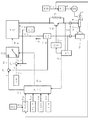
図1は、本発明の実施の形態1に係る消耗電極アーク溶接のくびれ検出時電流制御方法を実施するための溶接電源のブロック図である。同図は、上述した図5に、溶接速度設定回路WSを追加し、図5の遅延期間設定回路TDRを第2遅延期間設定回路TDR2に置換したものである。同図において、図5と同一のブロックについては、同一符号を付してそれらの説明は省略する。以下、同図を参照して、この異なるブロックについて説明する。
[Embodiment 1]
FIG. 1 is a block diagram of a welding power source for carrying out a current control method during constriction detection in consumable electrode arc welding according to
溶接速度設定回路WSは、予め定めた溶接速度設定信号Wsを出力する。ロボットを使用した溶接装置においては、溶接速度はロボット制御装置(図示は省略)に設定されるので、ロボット制御装置からこの溶接速度設定回路WSに溶接速度に関する情報が送られることになる。そして、この溶接速度設定回路WSは、送られてきた溶接速度に関する情報に基づいて溶接速度設定信号Wsを出力することになる。 The welding speed setting circuit WS outputs a predetermined welding speed setting signal Ws. In a welding apparatus using a robot, since the welding speed is set in a robot control device (not shown), information on the welding speed is sent from the robot control device to the welding speed setting circuit WS. And this welding speed setting circuit WS will output the welding speed setting signal Ws based on the sent information regarding the welding speed.
第2遅延期間設定回路TDR2は、上記の溶接速度設定信号Wsを入力として、予め定めた遅延期間設定関数によって遅延期間を算出して、遅延期間設定信号Tdrを出力する。この遅延期間設定関数については、図2で後述するが、この回路によって遅延期間設定信号Tdrは以下のように変化する値となる。
1) 溶接速度設定信号Wsの値が予め定めた基準速度Wt未満のときは、遅延期間設定信号Tdrの値を溶接速度設定信号Wsの値によらず一定とする。
2) 溶接速度設定信号Wsの値が上記の基準速度Wt以上のときは、遅延期間設定信号Tdrの値を溶接速度設定信号Wsの値に応じて変化させる。変化は、溶接速度設定信号Wsの値が大きくなるのに伴い、遅延期間設定信号Tdrの値は小さくなるようにする。すなわち、溶接速度が速くなるほど、遅延期間が短くなるように変化する。このときに遅延期間に下限値を設けても良い。もちろん、遅延期間は0未満にはならない。
The second delay period setting circuit TDR2 receives the welding speed setting signal Ws as described above, calculates a delay period using a predetermined delay period setting function, and outputs a delay period setting signal Tdr. The delay period setting function will be described later with reference to FIG. 2, but the delay period setting signal Tdr becomes a value that changes as follows by this circuit.
1) When the value of the welding speed setting signal Ws is less than the predetermined reference speed Wt, the value of the delay period setting signal Tdr is made constant regardless of the value of the welding speed setting signal Ws.
2) When the value of the welding speed setting signal Ws is equal to or higher than the reference speed Wt, the value of the delay period setting signal Tdr is changed according to the value of the welding speed setting signal Ws. The change is made so that the value of the delay period setting signal Tdr decreases as the value of the welding speed setting signal Ws increases. That is, the delay period changes so as to increase as the welding speed increases. At this time, a lower limit value may be provided for the delay period. Of course, the delay period will not be less than zero.
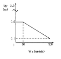
図2は、上述した第2遅延期間設定回路TDR2に内蔵されている遅延期間設定関数の一例を示す図である。同図の横軸は溶接速度設定信号Ws(cm/min)を示し、その範囲は0〜300cm/minである。縦軸は遅延期間設定信号Tdr(ms)を示し、その範囲は0〜3msである。同図は、シールドガスが炭酸ガス100%であり、母材の材質が鉄鋼であり、溶接ワイヤの直径が1.2mmであり、送給速度が850cm/min(溶接電流平均値250A)の場合である。以下同図を参照して説明する。 FIG. 2 is a diagram illustrating an example of a delay period setting function built in the above-described second delay period setting circuit TDR2. The horizontal axis of the figure shows the welding speed setting signal Ws (cm / min), and its range is 0 to 300 cm / min. The vertical axis represents the delay period setting signal Tdr (ms), and its range is 0 to 3 ms. The figure shows the case where the shielding gas is 100% carbon dioxide, the base material is steel, the welding wire diameter is 1.2 mm, and the feeding speed is 850 cm / min (welding current average value 250 A). It is. This will be described below with reference to FIG.
同図においては、基準速度Wt=50cm/minに設定されている。同図に示す関数では、溶接速度設定信号Wsの値がこの基準速度未満のときは、遅延期間設定信号Tdrは予め定めた遅延期間初期値Tdi=0.6msと一定値となっている。溶接速度設定信号Wsの値が基準速度以上のときは、その値に反比例して遅延期間設定信号Tdrの値は右肩下がりの直線状に変化している。そして、溶接速度設定信号Ws=300cm/minのときに、Tdr=0.1msとなっている。この溶接条件においては、溶接速度が300cm/min程度が溶接可能範囲の上限速度となる。 In the figure, the reference speed Wt is set to 50 cm / min. In the function shown in the figure, when the value of the welding speed setting signal Ws is less than the reference speed, the delay period setting signal Tdr is a constant value that is a predetermined delay period initial value Tdi = 0.6 ms. When the value of the welding speed setting signal Ws is equal to or higher than the reference speed, the value of the delay period setting signal Tdr changes in a straight line descending to the right in inverse proportion to the value. When the welding speed setting signal Ws = 300 cm / min, Tdr = 0.1 ms. Under these welding conditions, a welding speed of about 300 cm / min is the upper limit speed of the weldable range.
同図では、Ws≧Wtであるときの変化を直線としたが、曲線状であっても良い。その場合には、例えば下式のように関数を定義すれば良い。
Ws≧WtのときはTdr=(Tdi・Wt)/Ws
この式によれば、Ws=Wt=50cm/minのときはTdr=0.6msとなり、Ws=300cm/minのときはTdr=0.1msとなり、この両値は同図と同一となる。
In the figure, the change when Ws ≧ Wt is a straight line, but it may be curved. In that case, what is necessary is just to define a function like the following Formula, for example.
When Ws ≧ Wt, Tdr = (Tdi · Wt) / Ws
According to this equation, when Ws = Wt = 50 cm / min, Tdr = 0.6 ms, and when Ws = 300 cm / min, Tdr = 0.1 ms, both of which are the same as in FIG.
上記の基準速度Wt、遅延期間初期値Tdi及びWs≧Wtのときの遅延期間設定信号Tdrの変化パターンは、シールドガスの種類、母材の材質、溶接ワイヤの直径、送給速度等に応じて、実験によって適正値に設定される。 The change pattern of the delay period setting signal Tdr when the reference speed Wt, the delay period initial value Tdi, and Ws ≧ Wt are in accordance with the type of shielding gas, the material of the base material, the diameter of the welding wire, the feeding speed, and the like. It is set to an appropriate value by experiment.
同図における各信号のタイミングチャートは、上述した図6と同一であるので、説明は省略する。但し、図6の遅延期間Tdが、溶接速度によって変化することになる。 The timing chart of each signal in the figure is the same as that in FIG. However, the delay period Td in FIG. 6 varies depending on the welding speed.
次に、上述した実施の形態1の作用効果について説明する。溶接速度が基準速度Wt未満である比較的遅い速度のときは、従来技術と同様に、溶滴移行に伴う溶融池の振動が充分に収まる時間長さに遅延期間を設定すれば良い。溶接速度がこの範囲で変化するときには、遅延期間が一定値(遅延期間初期値Tdi)であっても溶接状態は不安定になることはない。この範囲において、溶接速度が遅くなるのに伴い遅延期間を長くなるように変化させると、ビード外観が悪くなる問題が生じる。したがって、この範囲では、遅延期間は一定値である方が良い。溶接速度が基準速度Wt以上になると、溶接速度に反比例して遅延期間が短くなる。これにより、溶接状態が不安定になることを抑制した上で、溶滴移行に伴う溶融池の振動がほぼ収まるように遅延期間を設定することができるので、スパッタの発生も抑制することができる。この理由は、溶接速度が速くなると、単位長さ当たりの溶融池の体積が小さくなるために、振動が収まる時間が短くなるからである。したがって、実施の形態1によれば、遅延期間が溶接速度に応じて自動的に適正化されるので、溶接速度が速くなっても、アーク再発生時のスパッタの発生を抑制し、かつ、溶接状態が不安定になることを抑制することができる。 Next, the function and effect of the first embodiment will be described. When the welding speed is a relatively slow speed that is less than the reference speed Wt, the delay period may be set to a length of time in which the vibration of the molten pool accompanying the droplet transfer is sufficiently contained, as in the prior art. When the welding speed changes within this range, the welding state does not become unstable even if the delay period is a constant value (delay period initial value Tdi). In this range, if the delay period is changed to become longer as the welding speed becomes slower, there is a problem that the bead appearance is deteriorated. Therefore, in this range, the delay period should be a constant value. When the welding speed is equal to or higher than the reference speed Wt, the delay period is shortened in inverse proportion to the welding speed. Thereby, after suppressing that the welding state becomes unstable, the delay period can be set so that the vibration of the molten pool accompanying the droplet transfer can be almost settled, so that the occurrence of spatter can also be suppressed. . The reason for this is that as the welding speed increases, the volume of the molten pool per unit length decreases, so the time for the vibration to settle is shortened. Therefore, according to the first embodiment, since the delay period is automatically optimized according to the welding speed, even when the welding speed is increased, the occurrence of spatter during arc re-generation is suppressed, and welding is performed. It can suppress that a state becomes unstable.
[実施の形態2]
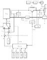
図3は、本発明の実施の形態2に係る消耗電極アーク溶接のくびれ検出時電流制御方法を実施するための溶接電源のブロック図である。同図は、上述した図1と対応しており、同一のブロックには同一符号を付して、それらの説明は省略する。同図は、図1の第2遅延期間設定回路TDR2を第3遅延期間設定回路TDR3に置換したものである。以下、同図を参照して、この異なるブロックについて説明する。
[Embodiment 2]
FIG. 3 is a block diagram of a welding power source for carrying out the current control method during constriction detection in consumable electrode arc welding according to
第3遅延期間設定回路TDR3は、送給速度設定信号Fr及び溶接速度設定信号Wsを入力として、送給速度設定信号Frの値が予め定めた基準送給速度Ft未満のときは予め定めた低送給速度時遅延期間LTdを遅延期間設定信号Tdrとして出力し、送給速度設定信号Frの値が上記の基準送給速度Ft以上のときは予め定めた遅延期間設定関数によって遅延期間を算出して、遅延期間設定信号Tdrを出力する。この遅延期間設定関数は、実施の形態1と同様である。この回路によって遅延期間設定信号Tdrは以下のように変化する値となる。
1) 送給速度設定信号Frの値が予め定めた基準送給速度Ft未満のときは、予め定めた低送給速度時遅延期間LTdを遅延期間設定信号Tdrとして出力する。
2) Fr≧Ftのときは、以下のようになる。
21) 溶接速度設定信号Wsの値が予め定めた基準速度Wt未満のときは、遅延期間設定信号Tdrの値を溶接速度設定信号Wsの値によらず一定とする。
22) 溶接速度設定信号Wsの値が上記の基準速度Wt以上のときは、遅延期間設定信号Tdrの値を溶接速度設定信号Wsの値に応じて変化させる。変化は、溶接速度設定信号Wsの値が大きくなるのに伴い、遅延期間設定信号Tdrの値は小さくなるようにする。すなわち、溶接速度が速くなるほど、遅延期間が短くなるように変化する。
The third delay period setting circuit TDR3 receives the feed speed setting signal Fr and the welding speed setting signal Ws as input, and when the value of the feed speed setting signal Fr is less than a predetermined reference feed speed Ft, a predetermined low speed is set. The delay period LTd at the feeding speed is output as the delay period setting signal Tdr, and when the value of the feeding speed setting signal Fr is equal to or higher than the reference feeding speed Ft, the delay period is calculated by a predetermined delay period setting function. The delay period setting signal Tdr is output. This delay period setting function is the same as in the first embodiment. With this circuit, the delay period setting signal Tdr has a value that varies as follows.
1) When the value of the feeding speed setting signal Fr is less than a predetermined reference feeding speed Ft, a predetermined low feeding speed delay period LTd is output as the delay period setting signal Tdr.
2) When Fr ≧ Ft:
21) When the value of the welding speed setting signal Ws is less than the predetermined reference speed Wt, the value of the delay period setting signal Tdr is made constant regardless of the value of the welding speed setting signal Ws.
22) When the value of the welding speed setting signal Ws is equal to or higher than the reference speed Wt, the value of the delay period setting signal Tdr is changed according to the value of the welding speed setting signal Ws. The change is made so that the value of the delay period setting signal Tdr decreases as the value of the welding speed setting signal Ws increases. That is, the delay period changes so as to increase as the welding speed increases.
実施の形態2と実施の形態1との相違点は、送給速度が基準送給速度Ft未満のときの遅延期間を一定値(低送給速度時遅延期間LTd)としたことである。炭酸ガスアーク溶接、マグ溶接、ミグ溶接等の代表的な消耗電極アーク溶接においては、送給速度が遅いときは溶滴移行形態が短絡移行形態となり、送給速度が速くなるとグロビュール移行形態又はスプレー移行形態となる。グロビュール移行形態又はスプレー移行形態であっても、溶接欠陥の発生を防止するために、短絡を伴うようにアーク長(溶接電圧)を設定する。上記の基準送給速度Ftは、溶滴移行形態がこの短絡移行形態である送給速度の略上限値になるように設定される。例えば、炭酸ガスアーク溶接において、溶接ワイヤの直径が1.2mmであるときは、基準送給速度Ft=5m/min(溶接電流平均値180A程度)に設定される。上記の低送給速度時遅延期間LTdは、送給速度が基準送給速度Ftよりも少し速いときの、上述した遅延期間設定関数における遅延期間初期値Tdiと同一値又はそれよりも大きな値に設定される。基準送給速度Ft及び低送給速度時遅延期間LTdは、シールドガスの種類(溶接法)、母材の材質、溶接ワイヤの直径等に応じて、実験によって適正値に設定される。 The difference between the second embodiment and the first embodiment is that the delay period when the feed speed is less than the reference feed speed Ft is set to a constant value (delay period at low feed speed LTd). In typical consumable electrode arc welding such as carbon dioxide arc welding, mag welding, and MIG welding, when the feed rate is slow, the droplet transfer mode becomes the short-circuit transfer mode, and when the feed rate increases, the globule transfer mode or spray transfer It becomes a form. Even in the globule transfer mode or spray transfer mode, the arc length (welding voltage) is set so as to be accompanied by a short circuit in order to prevent the occurrence of welding defects. The reference feed speed Ft is set so that the droplet transfer form is a substantially upper limit value of the feed speed that is the short-circuit transfer form. For example, in carbon dioxide arc welding, when the diameter of the welding wire is 1.2 mm, the reference feed speed Ft is set to 5 m / min (welding current average value of about 180 A). The low feed speed delay period LTd is the same value as the delay period initial value Tdi in the delay period setting function or a value larger than that when the feed speed is slightly faster than the reference feed speed Ft. Is set. The reference feed speed Ft and the low feed speed delay period LTd are set to appropriate values by experiments according to the type of shield gas (welding method), the material of the base material, the diameter of the welding wire, and the like.
同図における各信号のタイミングチャートは、上述した図6と同一であるので、説明は省略する。但し、図6の遅延期間Tdが、送給速度及び溶接速度によって変化することになる。 The timing chart of each signal in the figure is the same as that in FIG. However, the delay period Td in FIG. 6 varies depending on the feeding speed and the welding speed.
次に、上述した実施の形態2の作用効果について説明する。送給速度が基準送給速度Ft以上のときの作用効果については、上述した実施の形態1と同様であるので、説明は省略する。送給速度が基準送給速度Ft未満のときは、上述したように、溶滴移行形態は短絡移行形態となる。短絡移行形態では、アーク期間と短絡期間とが規則正しく繰り返されており、溶滴移行も安定している。このために、溶接速度が変化したときの遅延期間が一定値であっても、溶接状態が不安定になることはない。短絡移行形態においては、遅延期間を変化させない方が、ビード外観がさらに良好になる。したがって、送給速度が基準送給速度Ft未満のときは溶接速度が変化しても遅延期間を一定値に維持することによって、スパッタの発生及び溶接状態の不安定を抑制した上で、ビード外観がさらに良好になる。 Next, the function and effect of the second embodiment will be described. Since the operation and effect when the feeding speed is equal to or higher than the reference feeding speed Ft are the same as those in the first embodiment, the description thereof is omitted. When the feed rate is less than the reference feed rate Ft, as described above, the droplet transfer mode is a short-circuit transfer mode. In the short circuit transfer mode, the arc period and the short circuit period are regularly repeated, and the droplet transfer is also stable. For this reason, even if the delay period when the welding speed changes is a constant value, the welding state does not become unstable. In the short-circuit transition mode, the bead appearance is further improved when the delay period is not changed. Therefore, when the feed rate is less than the reference feed rate Ft, the delay period is maintained at a constant value even if the welding rate is changed, thereby suppressing the occurrence of spatter and the instability of the weld state, and the bead appearance. Becomes even better.
1 溶接ワイヤ
1a 溶滴
1b くびれ
2 母材
2a 溶融池
3 アーク
4 溶接トーチ
5 送給ロール
Dr 駆動信号
Ea 誤差増幅信号
EI 電流誤差増幅回路
Ei 電流誤差増幅信号
EV 電圧誤差増幅回路
Ev 電圧誤差増幅信号
FC 送給制御回路
Fc 送給制御信号
FR 送給速度設定回路
Fr 送給速度設定信号
Ft 基準送給速度
Ia アーク再発生時の電流値
ID 電流検出回路
Id 電流検出信号
Ih 高アーク電流値
IHR 高アーク電流設定回路
Ihr 高アーク電流設定信号
Im 低くびれ電流値
IMR 低くびれ電流設定回路
Imr 低くびれ電流設定信号
Ir 電流設定信号
Iw 溶接電流
LTd 低送給速度時遅延期間
ND くびれ検出回路
Nd くびれ検出信号
NIC くびれ検出時電流制御回路
PM 電源主回路
R 抵抗器
SW 電源特性切換回路
Sw 電源特性切換信号
Ta アーク期間
Td 遅延期間
Tdi 遅延期間初期値
TDR 遅延期間設定回路
Tdr 遅延期間設定信号
TDR2 第2遅延期間設定回路
TDR3 第3遅延期間設定回路
Tn くびれ検出期間
TR トランジスタ
Ts 短絡期間
Tu 上昇期間
TUR 上昇期間設定回路
Tur 上昇期間設定信号
VD 電圧検出回路
Vd 電圧検出信号
Vo 出力電圧
VR 電圧設定回路
Vr 電圧設定信号
Vs 短絡電圧値
Vta アーク判別値
Vtn くびれ検出基準値
Vw 溶接電圧
WM 送給モータ
WS 溶接速度設定回路
Ws 溶接速度設定信号
Wt 基準速度
ΔV 電圧上昇値
DESCRIPTION OF SYMBOLS 1 Welding wire 1a Droplet 1b Constriction 2 Base material 2a Weld pool 3 Arc 4 Welding torch 5 Feed roll Dr Drive signal Ea Error amplification signal EI Current error amplification circuit Ei Current error amplification signal EV Voltage error amplification circuit Ev Voltage error amplification signal FC feed control circuit Fc feed control signal FR feed speed setting circuit Fr feed speed setting signal Ft reference feed speed Ia current value ID when arc is regenerated current detection circuit Id current detection signal Ih high arc current value IHR high Arc current setting circuit Ihr High arc current setting signal Im Low constriction current value IMR Low constriction current setting circuit Imr Low constriction current setting signal Ir Current setting signal Iw Welding current LTd Low feed rate delay period ND Constriction detection circuit Nd Constriction detection signal NIC Constriction detection current control circuit PM Power supply main circuit R Resistor SW Power supply characteristic switching circuit Sw Power supply characteristic Conversion signal Ta Arc period Td Delay period Tdi Delay period initial value TDR Delay period setting circuit Tdr Delay period setting signal TDR2 Second delay period setting circuit TDR3 Third delay period setting circuit Tn Neck detection period TR Transistor Ts Short circuit period Tu Rising period TUR Rising period setting circuit Tur Rising period setting signal VD Voltage detection circuit Vd Voltage detection signal Vo Output voltage VR Voltage setting circuit Vr Voltage setting signal Vs Short-circuit voltage value Vta Arc discrimination value Vtn Necking detection reference value Vw Welding voltage WM Feeding motor WS Welding Speed setting circuit Ws Welding speed setting signal Wt Reference speed ΔV Voltage rise value
Claims (2)
溶接速度が予め定めた基準速度未満のときは前記遅延期間を前記溶接速度の値によらず一定とし、前記溶接速度が前記基準速度以上のときは前記遅延期間を前記溶接速度の値に応じて変化させる、
ことを特徴とする消耗電極アーク溶接のくびれ検出時電流制御方法。 In consumable electrode arc welding in which the consumable electrode is fed at a predetermined feeding speed and the arc generation state and the short circuit state are repeated between the consumable electrode and the base material, and the arc is regenerated from the short circuit state. When the necking of the droplet, which is a precursor phenomenon, is detected, and the necking is detected, the welding current applied to the short-circuit load is reduced, and the welding current is detected when a predetermined delay period elapses after the arc is regenerated. In the current control method at the time of constriction detection of consumable electrode arc welding that increases the current to the arc load,
When the welding speed is less than a predetermined reference speed, the delay period is constant regardless of the value of the welding speed, and when the welding speed is equal to or higher than the reference speed, the delay period is set according to the value of the welding speed. Change,
A current control method for detecting a constriction in consumable electrode arc welding.
ことを特徴とする請求項1記載の消耗電極アーク溶接のくびれ検出時電流制御方法。 When the feed speed is less than a predetermined reference feed speed, the delay period is constant regardless of the welding speed value.
The current control method for detecting constriction in consumable electrode arc welding according to claim 1.
Priority Applications (2)
| Application Number | Priority Date | Filing Date | Title |
|---|---|---|---|
| JP2011237481A JP5851798B2 (en) | 2011-10-28 | 2011-10-28 | Current control method for constriction detection in consumable electrode arc welding |
| CN201210400698.7A CN103084705B (en) | 2011-10-28 | 2012-10-19 | The current control method when necking down of consumable electrode arc welding detects |
Applications Claiming Priority (1)
| Application Number | Priority Date | Filing Date | Title |
|---|---|---|---|
| JP2011237481A JP5851798B2 (en) | 2011-10-28 | 2011-10-28 | Current control method for constriction detection in consumable electrode arc welding |
Publications (2)
| Publication Number | Publication Date |
|---|---|
| JP2013094792A true JP2013094792A (en) | 2013-05-20 |
| JP5851798B2 JP5851798B2 (en) | 2016-02-03 |
Family
ID=48198107
Family Applications (1)
| Application Number | Title | Priority Date | Filing Date |
|---|---|---|---|
| JP2011237481A Active JP5851798B2 (en) | 2011-10-28 | 2011-10-28 | Current control method for constriction detection in consumable electrode arc welding |
Country Status (2)
| Country | Link |
|---|---|
| JP (1) | JP5851798B2 (en) |
| CN (1) | CN103084705B (en) |
Families Citing this family (3)
| Publication number | Priority date | Publication date | Assignee | Title |
|---|---|---|---|---|
| JP6144137B2 (en) * | 2013-07-18 | 2017-06-07 | 株式会社ダイヘン | 2-wire welding control method |
| JP6134601B2 (en) * | 2013-07-23 | 2017-05-24 | 株式会社ダイヘン | Necking detection control method for welding power source |
| CN110076415B (en) * | 2018-01-26 | 2021-11-19 | 株式会社达谊恒 | Arc welding control method |
Citations (4)
| Publication number | Priority date | Publication date | Assignee | Title |
|---|---|---|---|---|
| JPH0366473A (en) * | 1987-12-21 | 1991-03-22 | Lincoln Electric Co:The | Device and method for short circuiting arc welding |
| JP2006247710A (en) * | 2005-03-11 | 2006-09-21 | Daihen Corp | Electric current control method in detecting constriction in consumable electrode arc welding |
| JP2006334601A (en) * | 2005-05-31 | 2006-12-14 | Matsushita Electric Ind Co Ltd | Pulse arc welding control method and pulse arc welding equipment |
| JP2007253232A (en) * | 2006-03-27 | 2007-10-04 | Daihen Corp | Method for detecting/controlling constriction in consumable electrode arc welding |
Family Cites Families (7)
| Publication number | Priority date | Publication date | Assignee | Title |
|---|---|---|---|---|
| JP4739641B2 (en) * | 2002-09-26 | 2011-08-03 | 株式会社ダイヘン | Power supply device for short-circuit arc welding and robot welding device |
| JP4907892B2 (en) * | 2005-03-31 | 2012-04-04 | 株式会社ダイヘン | Constriction detection control method for consumable electrode arc welding |
| JP4739874B2 (en) * | 2005-09-12 | 2011-08-03 | 株式会社ダイヘン | Constriction detection control method for consumable electrode arc welding |
| JP4965311B2 (en) * | 2007-03-12 | 2012-07-04 | 株式会社ダイヘン | Constriction detection control method for consumable electrode AC arc welding |
| JP4062361B2 (en) * | 2007-05-07 | 2008-03-19 | 松下電器産業株式会社 | Control method of arc welding apparatus and arc welding apparatus |
| JP5038206B2 (en) * | 2007-11-26 | 2012-10-03 | 株式会社ダイヘン | Constriction detection control method for consumable electrode arc welding |
| JP5199910B2 (en) * | 2009-02-12 | 2013-05-15 | 株式会社神戸製鋼所 | Welding control apparatus for consumable electrode type pulse arc welding, arc length control method thereof, and welding system equipped with the welding control apparatus |
-
2011
- 2011-10-28 JP JP2011237481A patent/JP5851798B2/en active Active
-
2012
- 2012-10-19 CN CN201210400698.7A patent/CN103084705B/en active Active
Patent Citations (4)
| Publication number | Priority date | Publication date | Assignee | Title |
|---|---|---|---|---|
| JPH0366473A (en) * | 1987-12-21 | 1991-03-22 | Lincoln Electric Co:The | Device and method for short circuiting arc welding |
| JP2006247710A (en) * | 2005-03-11 | 2006-09-21 | Daihen Corp | Electric current control method in detecting constriction in consumable electrode arc welding |
| JP2006334601A (en) * | 2005-05-31 | 2006-12-14 | Matsushita Electric Ind Co Ltd | Pulse arc welding control method and pulse arc welding equipment |
| JP2007253232A (en) * | 2006-03-27 | 2007-10-04 | Daihen Corp | Method for detecting/controlling constriction in consumable electrode arc welding |
Also Published As
| Publication number | Publication date |
|---|---|
| CN103084705A (en) | 2013-05-08 |
| CN103084705B (en) | 2016-03-16 |
| JP5851798B2 (en) | 2016-02-03 |
Similar Documents
| Publication | Publication Date | Title |
|---|---|---|
| JP4965311B2 (en) | Constriction detection control method for consumable electrode AC arc welding | |
| JP2012006020A (en) | Arc welding control method | |
| JP5801058B2 (en) | Welding apparatus and carbon dioxide arc welding method | |
| JP5840921B2 (en) | Constriction detection control method for consumable electrode arc welding | |
| JP2007283393A (en) | Method of controlling polarity change of consumable electrode ac pulsed arc welding | |
| JP2011073022A (en) | Carbon dioxide pulsed arc welding method | |
| JP5038206B2 (en) | Constriction detection control method for consumable electrode arc welding | |
| JP5822539B2 (en) | Welding equipment | |
| JP5770047B2 (en) | Welding equipment | |
| JP2009195952A (en) | Method for discriminating short circuit in consumable electrode arc welding | |
| JP5557249B2 (en) | Feed control method for arc welding with short circuit | |
| JP5622230B2 (en) | AC pulse arc welding control method | |
| JP5851798B2 (en) | Current control method for constriction detection in consumable electrode arc welding | |
| JP2014083571A (en) | Welding current control method during short-circuit period | |
| JP6245734B2 (en) | Welding current control method during short circuit period | |
| JP6144143B2 (en) | Welding current control method during short circuit period | |
| JP2012232312A (en) | Welding current control method during short circuit period | |
| JP5026289B2 (en) | Short-circuit detection method for consumable electrode arc welding | |
| JP5871360B2 (en) | Constriction detection control method for consumable electrode arc welding | |
| JP2013013920A (en) | Welding equipment | |
| JP2012110951A (en) | Method of controlling pulsed arc welding | |
| JP2010167489A (en) | Two-wire welding control method | |
| JP5706710B2 (en) | 2-wire welding control method | |
| JP2022143142A (en) | Arc-welding device | |
| JP2022134272A (en) | arc welding equipment |
Legal Events
| Date | Code | Title | Description |
|---|---|---|---|
| A621 | Written request for application examination |
Free format text: JAPANESE INTERMEDIATE CODE: A621 Effective date: 20140925 |
|
| A977 | Report on retrieval |
Free format text: JAPANESE INTERMEDIATE CODE: A971007 Effective date: 20151022 |
|
| TRDD | Decision of grant or rejection written | ||
| A01 | Written decision to grant a patent or to grant a registration (utility model) |
Free format text: JAPANESE INTERMEDIATE CODE: A01 Effective date: 20151126 |
|
| A61 | First payment of annual fees (during grant procedure) |
Free format text: JAPANESE INTERMEDIATE CODE: A61 Effective date: 20151203 |
|
| R150 | Certificate of patent or registration of utility model |
Ref document number: 5851798 Country of ref document: JP Free format text: JAPANESE INTERMEDIATE CODE: R150 |
|
| R250 | Receipt of annual fees |
Free format text: JAPANESE INTERMEDIATE CODE: R250 |
|
| R250 | Receipt of annual fees |
Free format text: JAPANESE INTERMEDIATE CODE: R250 |
|
| R250 | Receipt of annual fees |
Free format text: JAPANESE INTERMEDIATE CODE: R250 |
|
| R250 | Receipt of annual fees |
Free format text: JAPANESE INTERMEDIATE CODE: R250 |
|
| R250 | Receipt of annual fees |
Free format text: JAPANESE INTERMEDIATE CODE: R250 |
|
| R250 | Receipt of annual fees |
Free format text: JAPANESE INTERMEDIATE CODE: R250 |