JP2013083371A - Screw compressor - Google Patents
Screw compressor Download PDFInfo
- Publication number
- JP2013083371A JP2013083371A JP2011221659A JP2011221659A JP2013083371A JP 2013083371 A JP2013083371 A JP 2013083371A JP 2011221659 A JP2011221659 A JP 2011221659A JP 2011221659 A JP2011221659 A JP 2011221659A JP 2013083371 A JP2013083371 A JP 2013083371A
- Authority
- JP
- Japan
- Prior art keywords
- tube
- shell
- heat exchanger
- screw compressor
- leaf
- Prior art date
- Legal status (The legal status is an assumption and is not a legal conclusion. Google has not performed a legal analysis and makes no representation as to the accuracy of the status listed.)
- Pending
Links
Images

Classifications
-
- F—MECHANICAL ENGINEERING; LIGHTING; HEATING; WEAPONS; BLASTING
- F28—HEAT EXCHANGE IN GENERAL
- F28F—DETAILS OF HEAT-EXCHANGE AND HEAT-TRANSFER APPARATUS, OF GENERAL APPLICATION
- F28F1/00—Tubular elements; Assemblies of tubular elements
- F28F1/02—Tubular elements of cross-section which is non-circular
- F28F1/06—Tubular elements of cross-section which is non-circular crimped or corrugated in cross-section
-
- F—MECHANICAL ENGINEERING; LIGHTING; HEATING; WEAPONS; BLASTING
- F04—POSITIVE - DISPLACEMENT MACHINES FOR LIQUIDS; PUMPS FOR LIQUIDS OR ELASTIC FLUIDS
- F04C—ROTARY-PISTON, OR OSCILLATING-PISTON, POSITIVE-DISPLACEMENT MACHINES FOR LIQUIDS; ROTARY-PISTON, OR OSCILLATING-PISTON, POSITIVE-DISPLACEMENT PUMPS
- F04C18/00—Rotary-piston pumps specially adapted for elastic fluids
- F04C18/08—Rotary-piston pumps specially adapted for elastic fluids of intermeshing-engagement type, i.e. with engagement of co-operating members similar to that of toothed gearing
- F04C18/12—Rotary-piston pumps specially adapted for elastic fluids of intermeshing-engagement type, i.e. with engagement of co-operating members similar to that of toothed gearing of other than internal-axis type
- F04C18/14—Rotary-piston pumps specially adapted for elastic fluids of intermeshing-engagement type, i.e. with engagement of co-operating members similar to that of toothed gearing of other than internal-axis type with toothed rotary pistons
- F04C18/16—Rotary-piston pumps specially adapted for elastic fluids of intermeshing-engagement type, i.e. with engagement of co-operating members similar to that of toothed gearing of other than internal-axis type with toothed rotary pistons with helical teeth, e.g. chevron-shaped, screw type
-
- F—MECHANICAL ENGINEERING; LIGHTING; HEATING; WEAPONS; BLASTING
- F04—POSITIVE - DISPLACEMENT MACHINES FOR LIQUIDS; PUMPS FOR LIQUIDS OR ELASTIC FLUIDS
- F04C—ROTARY-PISTON, OR OSCILLATING-PISTON, POSITIVE-DISPLACEMENT MACHINES FOR LIQUIDS; ROTARY-PISTON, OR OSCILLATING-PISTON, POSITIVE-DISPLACEMENT PUMPS
- F04C23/00—Combinations of two or more pumps, each being of rotary-piston or oscillating-piston type, specially adapted for elastic fluids; Pumping installations specially adapted for elastic fluids; Multi-stage pumps specially adapted for elastic fluids
- F04C23/001—Combinations of two or more pumps, each being of rotary-piston or oscillating-piston type, specially adapted for elastic fluids; Pumping installations specially adapted for elastic fluids; Multi-stage pumps specially adapted for elastic fluids of similar working principle
-
- F—MECHANICAL ENGINEERING; LIGHTING; HEATING; WEAPONS; BLASTING
- F04—POSITIVE - DISPLACEMENT MACHINES FOR LIQUIDS; PUMPS FOR LIQUIDS OR ELASTIC FLUIDS
- F04C—ROTARY-PISTON, OR OSCILLATING-PISTON, POSITIVE-DISPLACEMENT MACHINES FOR LIQUIDS; ROTARY-PISTON, OR OSCILLATING-PISTON, POSITIVE-DISPLACEMENT PUMPS
- F04C29/00—Component parts, details or accessories of pumps or pumping installations, not provided for in groups F04C18/00 - F04C28/00
- F04C29/04—Heating; Cooling; Heat insulation
-
- F—MECHANICAL ENGINEERING; LIGHTING; HEATING; WEAPONS; BLASTING
- F28—HEAT EXCHANGE IN GENERAL
- F28D—HEAT-EXCHANGE APPARATUS, NOT PROVIDED FOR IN ANOTHER SUBCLASS, IN WHICH THE HEAT-EXCHANGE MEDIA DO NOT COME INTO DIRECT CONTACT
- F28D7/00—Heat-exchange apparatus having stationary tubular conduit assemblies for both heat-exchange media, the media being in contact with different sides of a conduit wall
- F28D7/16—Heat-exchange apparatus having stationary tubular conduit assemblies for both heat-exchange media, the media being in contact with different sides of a conduit wall the conduits being arranged in parallel spaced relation
-
- F—MECHANICAL ENGINEERING; LIGHTING; HEATING; WEAPONS; BLASTING
- F28—HEAT EXCHANGE IN GENERAL
- F28F—DETAILS OF HEAT-EXCHANGE AND HEAT-TRANSFER APPARATUS, OF GENERAL APPLICATION
- F28F9/00—Casings; Header boxes; Auxiliary supports for elements; Auxiliary members within casings
- F28F9/22—Arrangements for directing heat-exchange media into successive compartments, e.g. arrangements of guide plates
Landscapes
- Engineering & Computer Science (AREA)
- Mechanical Engineering (AREA)
- General Engineering & Computer Science (AREA)
- Physics & Mathematics (AREA)
- Thermal Sciences (AREA)
- Geometry (AREA)
- Heat-Exchange Devices With Radiators And Conduit Assemblies (AREA)
- Applications Or Details Of Rotary Compressors (AREA)
Abstract
【課題】シェルアンドチューブ式熱交換器を小形化することにより全体として小形化できるスクリュー圧縮機を得る。
【解決手段】
スクリュー圧縮機は、圧縮機本体と、該圧縮機本体から吐出された圧縮空気を冷却するためのシェルアンドチューブ式熱交換器を備えている。シェルアンドチューブ式熱交換器内に設けられているチューブ11は、両端側が円筒11a,11bで、且つ中央側が周方向に山部と谷部を交互に有した波形形状となるよう形成された多葉管11cで構成されている。また、前記チューブの中央側に設けられている多葉管の部分は捩じりを加えられた多葉スパイラル形状に構成されている。
【選択図】図5A screw compressor that can be reduced in size as a whole by downsizing a shell-and-tube heat exchanger.
[Solution]
The screw compressor includes a compressor body and a shell-and-tube heat exchanger for cooling the compressed air discharged from the compressor body. The tube 11 provided in the shell-and-tube heat exchanger is formed so as to have a corrugated shape in which both end sides are cylinders 11a and 11b, and the central side has alternately crests and troughs in the circumferential direction. It consists of a leaf tube 11c. Further, the multi-leaf tube portion provided on the center side of the tube is formed in a multi-leaf spiral shape to which twisting is applied.
[Selection] Figure 5
Description
本発明は、圧縮ガスを冷却するためのシェルアンドチューブ熱交換器を備えているスクリュー圧縮機に関する。 The present invention relates to a screw compressor including a shell and tube heat exchanger for cooling a compressed gas.
シェルアンドチューブ熱交換器を備えたスクリュー圧縮機の従来技術としては、特開2001−153080号公報(特許文献1)に記載のものがある。この特許文献1のものには、水冷式の2段オイルフリースクリュー圧縮機が記載され、そのインタークーラとアフタークーラに水冷式のシェルアンドチューブ式熱交換器が用いられており、一段側圧縮機本体や二段側圧縮機本体で圧縮されて高温となった圧縮空気(圧縮ガス)を冷却水で冷却するように構成している。
As a prior art of the screw compressor provided with the shell and tube heat exchanger, there is one described in JP 2001-153080 A (Patent Document 1). In this
前記特許文献1には、シェルアンドチューブ式熱交換器で構成されているインタークーラやアフタークーラの小形化を図ることに関しては十分な配慮が為されておらず、シェルアンドチューブ式熱交換器が大きいために、これを搭載したスクリュー圧縮機全体が大きなものとなってしまう課題があった。特に、1つのパッケージ内に圧縮機本体などと共にシェルアンドチューブ式熱交換器のインタークーラやアフタークーラを収容したスクリュー圧縮機においては、そのパッケージが大きくなり、容積占有率が大きくなってしまう課題がある。
In
本発明の目的は、シェルアンドチューブ式熱交換器を小形化することにより全体として小形化できるスクリュー圧縮機を得ることにある。 An object of the present invention is to obtain a screw compressor that can be downsized as a whole by downsizing a shell and tube heat exchanger.
上記課題を解決するために、本発明は、圧縮機本体と、該圧縮機本体から吐出された圧縮空気を冷却するためのシェルアンドチューブ式熱交換器を備えたスクリュー圧縮機において、前記シェルアンドチューブ式熱交換器内に設けられているチューブは、両端側が円筒で、且つ中央側が周方向に山部と谷部を交互に有した波形形状となるよう形成された多葉管で構成されていることを特徴とする。 In order to solve the above problems, the present invention provides a screw compressor including a compressor body and a shell-and-tube heat exchanger for cooling the compressed air discharged from the compressor body. The tube provided in the tube heat exchanger is composed of a multi-leaf tube formed so that both ends are cylindrical and the center side has a corrugated shape alternately having crests and troughs in the circumferential direction. It is characterized by being.
前記シェルアンドチューブ式熱交換器は、円筒状のシェルと、このシェルの両側に設けられたヘッダと、前記シェルの一端側に設けられ、シェル内と前記ヘッダの一方側とを水密に仕切るフランジと、前記シェルの他端側に設けられ、シェル内と前記ヘッダの他方側とを水密に仕切る管板と、前記前記シェルの両側に設けられたヘッダを連通するように前記フランジと前記管板に取り付けられた複数の前記チューブと、前記シェル内の長手方向に複数枚間隔を空けて配置され前記チューブが貫通する貫通孔を有すると共にシェル内に導入された流体を一方側から他方側に蛇行しながら導くためのバッフルプレートとを備える構成にすると良い。 The shell-and-tube heat exchanger includes a cylindrical shell, headers provided on both sides of the shell, and a flange provided on one end side of the shell to partition the inside of the shell and one side of the header in a watertight manner. A tube plate that is provided on the other end side of the shell and that tightly partitions the inside of the shell and the other side of the header, and the flange and the tube plate so that the headers provided on both sides of the shell communicate with each other. A plurality of tubes attached to the shell, and a plurality of tubes arranged at intervals in the longitudinal direction in the shell and having a through-hole through which the tube passes, and the fluid introduced into the shell meanders from one side to the other side A baffle plate for guiding while guiding is preferable.
ここで、前記バッフルプレートに形成された貫通孔の内径は、圧縮機運転により前記チューブ内に内圧が作用した状態における前記多葉管の部分の外径より大きく形成されていることが好ましい。 Here, it is preferable that the inner diameter of the through-hole formed in the baffle plate is larger than the outer diameter of the multi-leaf tube portion in a state where an internal pressure is applied to the tube by the compressor operation.
前記チューブの中央側に設けられている多葉管の部分は、捩じりを加えられた多葉スパイラル形状に構成すると良い。
また、前記チューブの多葉管の部分の外径を、該チューブ両端側の円筒の部分の外径より小さく構成すると良い。
The portion of the multileaf tube provided on the center side of the tube may be formed into a twisted multileaf spiral shape.
Further, the outer diameter of the multi-leaf tube portion of the tube may be smaller than the outer diameter of the cylindrical portion on both ends of the tube.
本発明によれば、シェルアンドチューブ式熱交換器の熱交換効率を向上することができるからその小形化を図ることができ、その結果全体として小形化可能なスクリュー圧縮機を得ることができる効果がある。 According to the present invention, the heat exchange efficiency of the shell-and-tube heat exchanger can be improved, so that the miniaturization thereof can be achieved, and as a result, a screw compressor that can be miniaturized as a whole can be obtained. There is.
以下、本発明のスクリュー圧縮機の実施例を図面に基づき説明する。なお、各図において、同一符号を付した部分は同一部分を示している。 Hereinafter, embodiments of the screw compressor of the present invention will be described with reference to the drawings. In addition, in each figure, the part which attached | subjected the same code | symbol has shown the same part.
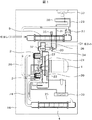
図1は、本発明のスクリュー圧縮機の実施例1を示す全体構成図で、本実施例におけるスクリュー圧縮機は水冷式2段オイルフリースクリュー圧縮機となっており、主モータ1により回転駆動される低段側(一段側)圧縮機本体2と高段側(二段側)圧縮機本体3が設けられ、低段側圧縮機本体2で圧縮され高温となった圧縮空気はインタークーラ(低圧段熱交換器)4で冷却される。冷却後の圧縮空気は高段側圧縮機本体3に送られ更に圧縮され、高段側圧縮本体3での圧縮により再び高温となった圧縮空気は、アフタークーラ(高圧段熱交換器)5で冷却され、その後、これらの機器を収納しているパッケージ16外へ排出されるように構成されている。
FIG. 1 is an overall configuration diagram showing a screw compressor according to a first embodiment of the present invention. The screw compressor in this embodiment is a water-cooled two-stage oil-free screw compressor, and is rotated by a
前記圧縮機本体2,3はギヤボックス20を介して前記主モータ1に連結されている。ギヤボックス20内には、主モータ1の回転駆動軸先端に取り付けられた大歯車21と、圧縮機本体2,3の回転従動軸先端にそれぞれ取り付けられ且つ前記大歯車21に噛み合う小歯車22,23が設けられている。主モータ1が回転することにより、その回転力が大歯車21及び小歯車22,23を介して圧縮機本体2,3に伝達され、圧縮機本体2,3を回転させて圧縮用空気を圧縮する。
The
前記低段側圧縮機本体2の吐出側には空気通路24を介して前記インタークーラ4が接続され、更にインタークーラ4には空気通路25を介して高段側圧縮機本体3の吸入側が接続されている。また、高段側圧縮機本体3の吐出側には空気通路26及び逆止弁27を介して前記アフタークーラ5が接続されている。前記インタークーラ4及びアフタークーラ5には冷却水(冷媒)が供給されており、低段側圧縮本体2や高段側圧縮機本体3で圧縮されて高温となった圧縮空気を冷却するように構成されている。
The
29は前記逆止弁27の手前で空気通路26から分岐された放気配管、30は前記放気配管30に接続された銅製のU字管からなる放風クーラ、31は前記放風クーラ30の下流側の放気配管で、この放気配管31の下流側は、吸込絞り弁32と連動して動作する放気弁33に接続されている。これら吸込絞り弁32や放気弁33によりアンローダ34が構成されている。なお、35は放風サイレンサ、36はサクションフィルタ、37は冷却ファンである。
また、38はギヤボックス20内のオイルを循環させるオイルポンプ、39はそのオイルを冷却するためのオイルクーラである。
29 is an air discharge pipe branched from the
上記構成の水冷式2段オイルフリー型のスクリュー圧縮機において、モータ1により低段側圧縮機本体2および高段側圧縮機本体3を回転駆動させると、圧縮用空気が外部から吸込絞り弁32を経由して低段側圧縮機本体2に吸入されて圧縮される。圧縮されて高温となった圧縮空気は低段側圧縮機本体2から吐出され、空気通路24を通ってインタークーラ4に流入し、ここで冷却される。冷却後の圧縮空気は空気通路25を通って高段側圧縮機本体3に吸入され、高段側圧縮機本体3で更に圧縮される。高段側圧縮機本体3から吐出された圧縮空気は、空気通路26および逆止弁27を経由してアフタークーラ5に流入する。高段側圧縮機本体3で更に圧縮された圧縮空気は再び高温となっているので、アフタークーラ5で実使用温度(例えば大気からの吸込温度に近い温度)まで冷却されてからパッケージ16外へ吐出される。
In the water-cooled two-stage oil-free screw compressor having the above-described configuration, when the low-
2段オイルフリースクリュー圧縮機では、上述したように、一般にインタークーラ4が用いられるが、これは高段側圧縮機へ流入する空気温度を下げることで、高段側圧縮機本体3から吐出される圧縮空気の温度が非常に高くなってしまうのを防止すると共に、高段側圧縮機本体3の圧縮効率を向上させるためである。
In the two-stage oil-free screw compressor, as described above, the
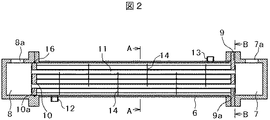
吐出される圧縮空気の温度を実使用温度まで冷却するために、上記インタークーラ4やアフタークーラ5はシェルアンドチューブ式熱交換器で構成されており、これらの熱交換器を圧縮機本体と共に1つの筐体内に収納してパッケージ化すると、パッケージ16内の熱交換器の容積占有率は大きなものとなっていた。このシェルアンドチューブ式熱交換器の構成を図2により説明する。
前記シェルアンドチューブ式熱交換器は、円筒状のシェル6、このシェル6の両側に設けられたヘッダ7,8、前記シェル6の一端側に設けられ、シェル6内と前記ヘッダ7,8の一方側とを水密に仕切るフランジ9、前記シェル6の他端側に設けられ、シェル6内と前記ヘッダ7,8の他方側とを水密に仕切る管板10、前記前記シェル6の両側に設けられた前記7,8ヘッダを連通するように前記フランジ9と前記管板10に取り付けられた複数本のチューブ11、前記シェル6内の長手方向に複数枚間隔を空けて配置され前記チューブ11が貫通する貫通孔(図示せず)を有するバッフルプレート14、前記シェル6の前記他端側に設けられシェル内に流体を導入するための入口12、前記シェル6における前記入口12側とは反対側に設けられ前記シェル6内に導入された流体を排出するための出口13などから構成されている。前記バッフルプレート14は、前記入口12からシェル6内に導入された流体を、一方側(本実施例では管板10側)から他方側(本実施例ではフランジ9側)に蛇行しながら導くためのものである。
In order to cool the temperature of the compressed air discharged to the actual use temperature, the
The shell and tube heat exchanger includes a
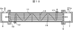
図2に示すシェルアンドチューブ式熱交換器が、例えば図1に示すアフタークーラ5として用いられている場合について、圧縮空気と冷却水の流れを図10により説明する。
高段側圧縮機本体3から吐出され、空気通路26及び逆止弁27を介して、シェルアンドチューブ式熱交換器の一端側のヘッダ7に入口部7aから導入された圧縮空気は、フランジ9の部分から複数本の各チューブ11内に流入し、他端側のヘッダ8へ流れて集合し、出口部8aから吐出される。一方、冷却水(冷媒としての流体)はシェル6に設けられた入口12からシェル6内に導入され、シェル6内の管板10側からバッフルプレート14により蛇行しながらフランジ9側に流れ、出口13から排出される。前記冷却水は、前記バッフルプレート14により、水平に設置されたチューブ11に対し垂直方向に流路を形成しながら流れる。
For example, when the shell and tube heat exchanger shown in FIG. 2 is used as the aftercooler 5 shown in FIG. 1, the flow of compressed air and cooling water will be described with reference to FIG.
The compressed air discharged from the high-
これにより、前記圧縮空気と前記冷却水とは対向流となり、前記チューブ11の管壁を介して高温の圧縮空気と低温の冷却水とが熱交換され、圧縮空気は外部に放出しても問題ない実使用温度まで冷却されてヘッダ8の出口部8aから吐出され、パッケージ外に供給される。
なお、前記シェルアンドチューブ式熱交換器がインタークーラ4として用いられている場合でもほぼ同様である。
As a result, the compressed air and the cooling water are opposed to each other, and the high-temperature compressed air and the low-temperature cooling water are heat-exchanged via the tube wall of the
In addition, even when the shell and tube heat exchanger is used as the
図2に戻り、シェルアンドチューブ式熱交換器に用いられている前記チューブ11としては、従来から、単純な円筒形状の単管(ベアチューブ)が用いられている。しかし、単純な円筒形状の単管を用いた場合、単管の伝熱面積は小さく、シェルアンドチューブ式熱交換器が大形化するため、圧縮機本体2,3などと共に、シェルアンドチューブ式熱交換器で構成されたインタークーラ4やアフタークーラ5などを1つの筐体内に収納してパッケージ化すると、スクリュー圧縮機が大形化してしまう。
Returning to FIG. 2, a simple cylindrical single tube (bare tube) is conventionally used as the
そこで、前記チューブ11の熱交換性能を向上させるため、前記チューブ11として、特開2008−232449号公報(以下特許文献2という)に記載されているような二重管式のチューブを採用することを検討した。前記特許文献2に記載されたている二重管式のチューブは、外管(外チューブ)と内管(内チューブ)で構成され、外管はベアチューブ(円筒管)で、内チューブは断面が多葉状の多葉管で構成されている二重管式の熱交換器である。前記内管と外管との間の間隙には第1の流体を流通させる一方、内管内には第2の流体を流通させ、内管として多葉管を採用することにより熱交換効率を向上させるようにしている。
Therefore, in order to improve the heat exchange performance of the
この特許文献2に記載された二重管式のチューブ(熱交換器)を、シェルアンドチューブ式熱交換器の前記チューブとして応用し、内管内通路だけでなく、内管と外管との間の通路にも圧縮機本体2または3からの圧縮空気を流すと共に、前記外管の外側には冷却水を流すように構成することを考えた。このようにすれば、同径の単管をシェルアンドチューブ式熱交換器のチューブ11として用いている従来のものに対して、前記チューブ11が二重管式のチューブとなっていることにより、伝熱面積を大きく取れ、熱交換効率を向上できると考えられる。
The double-pipe type tube (heat exchanger) described in
しかし、シェルアンドチューブ式熱交換器のチューブ11を、単管のチューブから二重管式のチューブに変えても、チューブ11に対する管外流体(冷却水)との接触面積は同径の単管で構成されたチューブと変わらないため、シェルアンドチューブ式熱交換器の熱交換効率は、複雑な構造の二重管式チューブを採用した割には十分な効果が期待できないことがわかった。
However, even if the
そこで、本実施例では、シェルアンドチューブ式熱交換器のチューブ11として図3〜図9に示すように、両端側が円筒で、且つ中央側が周方向に山部と谷部を交互に有した波形形状となるよう形成された多葉管で構成するようにした。本実施例のチューブ11としての多葉管は、二重管式のチューブではなく、単管のチューブ(一重チューブ)で構成されている。
Therefore, in this embodiment, as shown in FIGS. 3 to 9 as the
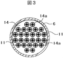
図3は図2のA−A線矢視断面図である。この図に示すように、チューブ11は多葉管で構成されている。また、図3に示すように、チューブ11はバッフルプレート14に形成されている貫通孔14aを貫通するように設けられており、前記貫通孔14aの内径は、ここを貫通する多葉管形状のチューブ11の外形よりも大きく構成されている。特に、圧縮機運転により、前記チューブ11内を圧縮空気が流通すると多葉管部分は内圧(例えば0.7MPaの内圧)が作用してその外径が大きくなるが、本実施例では、圧縮機運転によりチューブ内に内圧が作用した状態における前記多葉管の部分における外径よりも、前記貫通孔14aの内径の方が大きくなるように構成されている。
3 is a cross-sectional view taken along line AA in FIG. As shown in this figure, the
これにより、組立時にチューブ11をバッフルプレート14の貫通孔14aに挿入する作業を容易に行えるだけでなく、圧縮機運転時にチューブ11に内圧が作用してチューブ外径が大きくなった場合でも、バッフルプレート14に応力が発生するのを防止できるから、バッフルプレート14の破損を防止でき、より薄いバッフルプレートを使用することも可能となる。
Thereby, not only can the operation of inserting the
なお、前記バッフルプレート14は冷却水を蛇行させて流通させるものであるため、円板形状ではなく、その下部或いは上部などに切欠きを形成した形状となっている。また、バッフルプレート14は、前記フランジ9や管板10に固定されたタイロッド(図示せず)などにより位置決め固定されている。
Since the
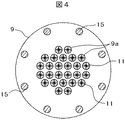
図4は図2のB−B線矢視断面図で、フランジ9の部分の側面図である。前記フランジ9は前記シェル6を構成する部材と前記ヘッダ7を構成する部材との間に挟まれてボルト15などにより締結されている。また、前記フランジ9には前記チューブ11を挿入して固定するための貫通孔9aが多数形成されており、前記チューブ11の一端部が挿入されて拡管機を用いて拡管されることで、チューブ11の端部を前記フランジ9の貫通孔9aに圧着して固定している。なお、ロー付等により固定しても良い。
4 is a cross-sectional view taken along line B-B in FIG. 2, and is a side view of the
前記チューブ11の詳細構成を図5〜図9により説明する。
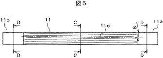
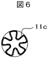
図5は図2に示すシェルアンドチューブ式熱交換器に用いられているチューブ11の全体構成を示す正面図である。この図に示すように、チューブ11はその両端側が円筒11a,11bで構成され、中央側は多葉管11cで構成されている。即ち、チューブ11の中央側の構成は、図5のC−C線矢視断面図である図6に示すように、周方向に山部と谷部を交互に有した波形形状となるように形成された多葉管11cで構成されている。本実施例では、前記多葉管11cは5葉に構成されている。また、前記チューブ11の両端側は図5のD−D線矢視断面図である図7に示すように、単純な円筒11a,11bで構成されている。
A detailed configuration of the
FIG. 5 is a front view showing the entire configuration of the
前記チューブ11の円筒11aの部分、即ち右端側は前記フランジ9の貫通孔9aに挿入されて固定されている。また、前記チューブ11の円筒11bの部分、即ち左端側は、図2に示すように、前記管板10に形成されている貫通孔10aに挿入されて、フランジ9側と同様に、拡管やロー付等により固定されている。なお、チューブ11の多葉管11cの部分の外径は、前記円筒11a,11bの部分の外径よりも小さく構成されており、チューブ11をフランジ9や管板10の貫通孔9a,10aに挿入して組み立てる作業を容易に行えるようにしている。
The portion of the
なお、前記管板10は前記シェル6内またはヘッダ8を構成する部材内を軸方向にスライドできるように構成されており、前記チューブが軸方向に熱膨張してもこれを吸収することが可能な構成となっている。16は、前記管板10の外周面と前記シェル6内面またはヘッダ8の構成部材内面との間に設けられてこれらの間を水密にシールするシール部材である。
The
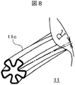
図8は、前記チューブ11の多葉管11cの部分の拡大斜視図である。この図8及び前記図5に示すように、本実施例においては、前記多葉管11cの部分が、図中のRで示すように、軸方向に向かうに従って周方向に一定角度で捩じりを加えられたスパイラル形状となっている。多葉管11cの部分をスパイラル形状に製作するには、円筒状の単管(ベアチューブ)に多葉管11cを形成するためのダイスをセットし、このダイスを軸方向に固定すると共に周方向には自由に回転できるようにする。この状態から前記円筒状の単管を引き抜くと、前記単管には前記ダイスがセットされた部分から単管を引き抜いた分だけ多葉管形状の部分が成形される。また、前記ダイスは周方向には自由に回転できるように軸方向にのみ位置決めされ、単管を引き抜く動作に連動するように前記ダイスは周方向に回転するように構成されているので、前記多葉管はスパイラル状に形成される。このスパイラル状多葉管の捩じり量(捩じり角R)は前記単管の引き抜き速度を変えることで、調整できるように構成されている。
FIG. 8 is an enlarged perspective view of the
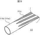
図9は、前記チューブ11の端部側部分の拡大斜視図である。この図9はチューブ11の左端側のみを示しているが、右端側についても同様に構成されている。この図に示すように、チューブ11の端部側は円筒11b(11a)のまま、即ちベアチューブのままの形状となっており、ダイスがセットされた部分から引き抜き動作を終了した部分までは図に示すように、多葉管11に形成されている。
FIG. 9 is an enlarged perspective view of an end side portion of the
チューブ11の両端側は円筒11a,11bに形成されていることにより、フランジ9や管板10に形成されている貫通孔9a,10aに挿入されて、拡管やロー付等により前記フランジ9や管板10に固定することが可能となる。また、チューブ11の中央側は多葉管11cとなっているので、チューブ11の伝熱面積を大きくすることができるから熱伝達効率を向上させることができる。従って、チューブ11の外側を流れる冷却水(冷媒)によりチューブ11の内側を流れる高温の圧縮空気を効率良く冷却することができ、シェルアンドチューブ式熱交換器を小形化することが可能となる。
Since both ends of the
また、多葉管11cの溝(図6に示す谷の部分)の部分は、チューブ11の両端側が円筒のままであるため、その両端部が堰となっている。このため、多葉管11cの溝に水が溜まった状態で圧縮機が停止し、冷却水の供給も停止した場合、水が前記溝に溜まったままとなり、腐食を発生させる虞がある。しかし、本実施例によれば、多葉管11cの部分は捩じられてスパイラル状となっているので、多葉管の溝の部分に溜まった水は、自重によりスパイラル状の溝に沿って下方に流れて落下し、前記溝に水は溜まらないから多葉管部の腐食も防止できる。
Moreover, since the both ends of the
更に、圧縮機運転中は多葉管11cの外側を冷却水が流れるが、前記多葉管11cはスパイラル状に形成されているため、チューブ11の外側を流れる冷却水の流れ、及びチューブ11の内側を流れる圧縮空気の流れが乱流化され、この結果、伝熱効率を更に向上することも可能となる。
Further, while the compressor is in operation, the cooling water flows outside the
なお、本実施例では、前記多葉管11cの部分をスパイラル状に形成するようにしているが、前記捩じり角Rを大きくするほど、伝熱面積を大きくできる。また、多葉管11cの部分は必ずしもスパイラル状に構成する必要はなく、捩じり角Rが0度のストレート形状としても良い。ストレート形状の多葉管とするには、前記ダイスの周方向回転を阻止するようにして単管を引き抜き加工すれば良い。ストレート形状とすることにより、伝熱面積は小さくなるが、多葉管11cの外側を流れる冷却水の圧力損失を低減することが可能となる。
In this embodiment, the portion of the
シェルアンドチューブ式熱交換器のチューブ11として、特許文献2に記載された多葉二重チューブを用いた場合と、上述した本実施例のシェルアンドチューブ式熱交換器とした場合について、熱交換性能を比較実験した結果を表1に示す。
As the
本実施例の場合、チューブ11を一重チューブとしているので、二重チューブに対して伝熱面積は少なくなるものの、多葉管としていることから冷却水との接触面積を大幅に増加することができる。このため、単位伝熱面積あたりの熱交換量を向上することができる。
In the case of the present embodiment, since the
従って、本実施例によれば、多葉二重チューブを用いた場合と同等にシェルアンドチューブ式熱交換器を小形化できる。しかも本実施例によれば、一重チューブであるため、構造が簡素化されて製作が容易になるだけでなく、チューブ11を製作するための材料費も大幅に低減することが可能となる。
Therefore, according to the present Example, a shell and tube type heat exchanger can be reduced in size similarly to the case where a multileaf double tube is used. Moreover, according to the present embodiment, since it is a single tube, not only the structure is simplified and the manufacture becomes easy, but also the material cost for manufacturing the

なお、上述した実施例では、水冷式2段オイルフリースクリュー圧縮機の場合について説明したが、単段オイルフリースクリュー圧縮機や油冷式のスクリュー圧縮機であっても、シェルアンドチューブ式熱交換器を用いて圧縮空気を冷却するものであれば、同様に本発明を実施することが可能である。 In the above-described embodiment, the case of the water-cooled two-stage oil-free screw compressor has been described. However, even in the case of a single-stage oil-free screw compressor or an oil-cooled screw compressor, shell-and-tube heat exchange is performed. The present invention can be similarly implemented as long as the compressed air is cooled using a vessel.
以上説明したように、本実施例によれば、圧縮機本体と、該圧縮機本体から吐出された圧縮空気を水冷式で冷却するシェルアンドチューブ式熱交換器を備えたスクリュー圧縮機において、前記シェルアンドチューブ式熱交換器内に設けられているチューブは、両端側が円筒で、中央側が周方向に山部と谷部を交互に有した波形形状となるよう形成された多葉管で構成されているので、シェルアンドチューブ式熱交換器の熱交換効率を向上することができるからその小形化を図ることができ、その結果全体として小形化可能なスクリュー圧縮機を得ることができる。 As described above, according to the present embodiment, in the screw compressor including the compressor body and the shell-and-tube heat exchanger that cools the compressed air discharged from the compressor body by a water cooling method, The tube provided in the shell-and-tube heat exchanger is composed of a multi-leaf tube formed in a corrugated shape in which both ends are cylindrical and the central side has alternating peaks and valleys in the circumferential direction. Therefore, since the heat exchange efficiency of the shell and tube heat exchanger can be improved, it is possible to reduce the size thereof, and as a result, it is possible to obtain a screw compressor that can be reduced in size as a whole.
また、シェルアンドチューブ式熱交換器内に設けられているチューブは、多葉管部を有する一重チューブにより構成されているから、二重チューブを用いた場合に比べ、構造を大幅に簡略化して冷却能力も向上できる小形化されたシェルアンドチューブ式熱交換器を搭載したスクリュー圧縮機が得られる。 In addition, the tube provided in the shell-and-tube heat exchanger is composed of a single tube with a multi-leaf tube part, so the structure is greatly simplified compared to the case of using a double tube. A screw compressor equipped with a miniaturized shell and tube heat exchanger capable of improving the cooling capacity can be obtained.
更に、前記チューブの中央側を、捩じりを加えた多葉スパイラル形状とすることにより、チューブ内外の伝熱面積を更に大きくすることができると共に、チューブ内外を流れる両流体を乱流状態とすることもできるから、熱交換性能を向上させて冷却能力を更に向上できる。しかも、管外を流れる流体が水などの液体の場合には、圧縮機停止時や圧縮機未使用時に多葉管の葉状溝部に液体流体が溜まる虞があるが、本実施例では、前記多葉管部をスパイラル形状としたことにより、前記葉状溝部に液体流体が溜まるのも防止でき、チューブに錆や腐食が発生するのも防止できる。 Furthermore, by making the central side of the tube into a multi-leaf spiral shape with twisting, the heat transfer area inside and outside the tube can be further increased, and both fluids flowing inside and outside the tube are in a turbulent state. Therefore, the heat exchange performance can be improved and the cooling capacity can be further improved. In addition, when the fluid flowing outside the tube is a liquid such as water, the liquid fluid may accumulate in the leaf-like groove of the multi-leaf tube when the compressor is stopped or when the compressor is not used. By making the leaf tube portion into a spiral shape, it is possible to prevent liquid fluid from accumulating in the leaf groove portion and to prevent rust and corrosion from occurring in the tube.
このように、本実施例によれば、小形で信頼性が高く構造を簡略化して安価に製作可能なシェルアンドチューブ式熱交換器を搭載したスクリュー圧縮機を得ることができる。 As described above, according to the present embodiment, it is possible to obtain a screw compressor equipped with a shell-and-tube heat exchanger that is small, reliable, simplified in structure, and can be manufactured at low cost.
1:主モータ、
2:低段側圧縮機本体、
3:高段側圧縮機本体、
4:インタークーラ(低圧段熱交換器)、5:アフタークーラ(高圧段熱交換器)、
6:シェル、
7,8:ヘッダ(7a:入口部、8a:出口部)、
9:フランジ(9a:貫通孔)、
10:管板(10a:貫通孔)、
11:チューブ(11a,11b:円筒、11c:多葉管)、
12:入口、13:出口、
14:バッフルプレート、
15:ボルト、
16:パッケージ、
20:ギヤボックス、21:大歯車、22,23:小歯車、
24,25,26:空気通路、27:逆止弁、
29,31:放気配管、30:放風クーラ、
32:吸込絞り弁、33:放気弁、34:アンローダ、
35:放風サイレンサ、36:サクションフィルタ、37:冷却ファン、
38:オイルポンプ、39:オイルクーラ。
1: main motor,
2: Low-stage compressor body,
3: High-stage compressor body,
4: Intercooler (low pressure stage heat exchanger), 5: After cooler (high pressure stage heat exchanger),
6: Shell,
7, 8: header (7a: inlet part, 8a: outlet part),
9: flange (9a: through hole),
10: Tube sheet (10a: Through hole),
11: Tube (11a, 11b: cylinder, 11c: multileaf tube),
12: Entrance, 13: Exit,
14: baffle plate,
15: Bolt,
16: Package,
20: Gear box, 21: Large gear, 22, 23: Small gear,
24, 25, 26: air passage, 27: check valve,
29, 31: Air discharge pipe, 30: Air discharge cooler,
32: Suction throttle valve, 33: Air release valve, 34: Unloader,
35: Ventilation silencer, 36: Suction filter, 37: Cooling fan,
38: Oil pump, 39: Oil cooler.
Claims (5)
前記シェルアンドチューブ式熱交換器内に設けられているチューブは、両端側が円筒で、且つ中央側が周方向に山部と谷部を交互に有した波形形状となるよう形成された多葉管で構成されている
ことを特徴とするスクリュー圧縮機。 In a screw compressor provided with a compressor body and a shell-and-tube heat exchanger for cooling the compressed air discharged from the compressor body,
The tube provided in the shell-and-tube heat exchanger is a multi-leaf tube formed so as to have a corrugated shape in which both ends are cylindrical and the center side has alternating peaks and valleys in the circumferential direction. It is comprised, The screw compressor characterized by the above-mentioned.
Priority Applications (3)
| Application Number | Priority Date | Filing Date | Title |
|---|---|---|---|
| JP2011221659A JP2013083371A (en) | 2011-10-06 | 2011-10-06 | Screw compressor |
| US13/591,707 US20130089413A1 (en) | 2011-10-06 | 2012-08-22 | Screw Compressor |
| CN2012103060448A CN103032334A (en) | 2011-10-06 | 2012-08-24 | Screw compressor |
Applications Claiming Priority (1)
| Application Number | Priority Date | Filing Date | Title |
|---|---|---|---|
| JP2011221659A JP2013083371A (en) | 2011-10-06 | 2011-10-06 | Screw compressor |
Publications (1)
| Publication Number | Publication Date |
|---|---|
| JP2013083371A true JP2013083371A (en) | 2013-05-09 |
Family
ID=48019597
Family Applications (1)
| Application Number | Title | Priority Date | Filing Date |
|---|---|---|---|
| JP2011221659A Pending JP2013083371A (en) | 2011-10-06 | 2011-10-06 | Screw compressor |
Country Status (3)
| Country | Link |
|---|---|
| US (1) | US20130089413A1 (en) |
| JP (1) | JP2013083371A (en) |
| CN (1) | CN103032334A (en) |
Cited By (7)
| Publication number | Priority date | Publication date | Assignee | Title |
|---|---|---|---|---|
| JP2015012889A (en) * | 2013-07-03 | 2015-01-22 | タニコー株式会社 | Noodle boiling machine |
| TWI726667B (en) * | 2019-04-23 | 2021-05-01 | 比利時商亞特拉斯可波克氣動股份有限公司 | A compressor or vacuum pump device, a liquid return system for such a compressor or vacuum pump device and a method for draining liquid from a gearbox of such a compressor or vacuum pump device |
| CN113027766A (en) * | 2021-03-10 | 2021-06-25 | 重庆奇螺流体设备有限公司 | Oil gas cooler of variable-frequency oil injection screw air compressor and system thereof |
| JP2022081037A (en) * | 2020-11-19 | 2022-05-31 | 株式会社スギノマシン | Multi-tube heat exchanger and wet atomizer |
| US11767847B2 (en) | 2019-04-23 | 2023-09-26 | Atlas Copco Airpower, Naamloze Vennootschap | Compressor or vacuum pump device, a liquid return system for such a compressor or vacuum pump device and a method for draining liquid from a gearbox of such a compressor or vacuum pump device |
| JP2024538030A (en) * | 2021-10-12 | 2024-10-18 | トレヴィ システムズ インコーポレイテッド | Polymeric tube-in-shell heat exchanger with twisted tubes |
| JP7836390B2 (en) | 2021-10-12 | 2026-03-26 | トレヴィ システムズ インコーポレイテッド | Polymer tube-in-shell heat exchanger with twisted tubes |
Families Citing this family (16)
| Publication number | Priority date | Publication date | Assignee | Title |
|---|---|---|---|---|
| WO2013049438A2 (en) | 2011-09-30 | 2013-04-04 | Eaton Corporation | Supercharger assembly with independent superchargers and motor/generator |
| US9534531B2 (en) | 2011-09-30 | 2017-01-03 | Eaton Corporation | Supercharger assembly for regeneration of throttling losses and method of control |
| US9534532B2 (en) * | 2011-09-30 | 2017-01-03 | Eaton Corporation | Supercharger assembly with two rotor sets |
| EP3239488A3 (en) | 2012-03-29 | 2017-11-22 | Eaton Corporation | Electric energy generation using variable speed hybrid electric supercharger assembly |
| CN105209731A (en) | 2013-03-12 | 2015-12-30 | 伊顿公司 | Adaptive state of charge regulation and control of variable speed hybrid electric supercharger assembly for efficient vehicle operation |
| US10375901B2 (en) | 2014-12-09 | 2019-08-13 | Mtd Products Inc | Blower/vacuum |
| US10746177B2 (en) | 2014-12-31 | 2020-08-18 | Ingersoll-Rand Industrial U.S., Inc. | Compressor with a closed loop water cooling system |
| US20160370120A1 (en) * | 2015-06-19 | 2016-12-22 | Ingersoll-Rand Company | Modular bonnet for variable-pass heat exchanger |
| GB201513415D0 (en) | 2015-07-30 | 2015-09-16 | Senior Uk Ltd | Finned coaxial cooler |
| US10995998B2 (en) | 2015-07-30 | 2021-05-04 | Senior Uk Limited | Finned coaxial cooler |
| GB2559182B (en) * | 2017-01-30 | 2021-01-06 | Senior Uk Ltd | Finned heat exchangers |
| GB2571637B (en) * | 2017-01-30 | 2021-01-13 | Senior Uk Ltd | Finned heat exchangers |
| GB2587567B (en) * | 2017-01-30 | 2021-09-22 | Senior Uk Ltd | Finned coaxial cooler |
| US10809008B2 (en) * | 2018-05-03 | 2020-10-20 | Ingersoll-Rand Industrial U.S., Inc. | Compressor systems and heat exchangers |
| CN113431779B (en) * | 2021-07-29 | 2023-04-25 | 广东温博节能环保科技有限公司 | Two-stage compression screw air compressor |
| CN118391938B (en) * | 2024-04-12 | 2025-10-03 | 武汉理工大学三亚科教创新园 | Heat exchanger with controllable heat transfer coefficient and use method thereof |
Citations (16)
| Publication number | Priority date | Publication date | Assignee | Title |
|---|---|---|---|---|
| JPS5421966A (en) * | 1977-07-20 | 1979-02-19 | Nippon Shokubai Kagaku Kogyo Co Ltd | Vapor-phase catalytic oxidizing method |
| US4256783A (en) * | 1977-07-13 | 1981-03-17 | Nippon Skokubei Kagaku Kogyo Co., Ltd. | Catalytic vapor phase oxidation reactor apparatus |
| JPS5944585A (en) * | 1982-09-06 | 1984-03-13 | Toshiba Corp | Heat exchanger |
| JPS61154464U (en) * | 1985-03-19 | 1986-09-25 | ||
| JPS61285390A (en) * | 1985-06-13 | 1986-12-16 | Toshiba Corp | Heat exchanger |
| JPH09152289A (en) * | 1995-11-29 | 1997-06-10 | Sanyo Electric Co Ltd | Absorption refrigerating machine |
| JPH09158870A (en) * | 1995-12-07 | 1997-06-17 | Hitachi Ltd | Water-cooled two-stage oil-free screw compressor |
| JPH10314837A (en) * | 1997-03-12 | 1998-12-02 | Nisshin Steel Co Ltd | Helical deformed tube, method for forming and device therefor |
| JP2004060465A (en) * | 2002-07-25 | 2004-02-26 | Hino Motors Ltd | EGR cooler |
| JP2005520673A (en) * | 2002-03-15 | 2005-07-14 | エイチ2ジーイーエヌ・イノベーションズ・インコーポレイテッド | Method and apparatus for minimizing deleterious effects of thermal expansion in heat exchange reactors |
| JP2005349419A (en) * | 2004-06-08 | 2005-12-22 | T Rad Co Ltd | Manufacturing method of heat exchanger tube and the tube |
| JP2006090641A (en) * | 2004-09-24 | 2006-04-06 | Mitsutomi Enji:Kk | Heat exchanger and carbon black production system |
| US20060144585A1 (en) * | 2004-12-10 | 2006-07-06 | Lg Electronics Inc. | Exhaust gas heat exchanger for cogeneration system |
| JP2007100990A (en) * | 2005-09-30 | 2007-04-19 | Matsumoto Jukogyo Kk | Heat exchanger |
| US20090008074A1 (en) * | 2007-07-02 | 2009-01-08 | Vamvakitis Dimitri L | Tubular heat exchanger |
| JP2010270931A (en) * | 2009-05-19 | 2010-12-02 | Nekken Sangyo Kk | Multitubular heat exchanger |
Family Cites Families (13)
| Publication number | Priority date | Publication date | Assignee | Title |
|---|---|---|---|---|
| US2365688A (en) * | 1943-06-23 | 1944-12-26 | Clarence L Dewey | Heat exchanger assembly |
| EP0112366A1 (en) * | 1982-06-29 | 1984-07-04 | AB Zander & Ingestrom | Tube heat exchanger |
| US4699211A (en) * | 1983-02-28 | 1987-10-13 | Baltimore Aircoil Company, Inc. | Segmental baffle high performance shell and tube heat exchanger |
| JPH02290495A (en) * | 1990-04-09 | 1990-11-30 | Kobe Steel Ltd | Air cooler of oil-free type screw air compressor |
| US5251693A (en) * | 1992-10-19 | 1993-10-12 | Zifferer Lothar R | Tube-in-shell heat exchanger with linearly corrugated tubing |
| US6488079B2 (en) * | 2000-12-15 | 2002-12-03 | Packless Metal Hose, Inc. | Corrugated heat exchanger element having grooved inner and outer surfaces |
| JP4440574B2 (en) * | 2003-08-04 | 2010-03-24 | 株式会社ティラド | Double tube heat exchanger and manufacturing method thereof |
| JP2006046846A (en) * | 2004-08-06 | 2006-02-16 | Matsumoto Jukogyo Kk | Double pipe heat exchanger |
| JP5110882B2 (en) * | 2007-01-05 | 2012-12-26 | 株式会社日立産機システム | Oil-free screw compressor |
| JP2008232449A (en) * | 2007-03-16 | 2008-10-02 | Sumitomo Light Metal Ind Ltd | Double tube heat exchanger and method for manufacturing the same |
| ITMI20080408A1 (en) * | 2008-03-10 | 2009-09-11 | Ferroli Spa | HEAT EXCHANGER, PARTICULARLY FOR THERMAL GENERATORS. |
| IT1393847B1 (en) * | 2009-03-31 | 2012-05-11 | R I Stampi Articoli Ind Di Zen Bortolo Sa | TUBULAR DEVICE FOR THE TRANSIT OF A HEAT EXCHANGE FLUID PARTICULARLY FOR HEAT EXCHANGERS, AND LIQUID / AERIFORM HEAT EXCHANGER, PARTICULARLY FOR BOILERS, INCLUDING A SERIES OF SUCH TUBULAR DEVICES |
| JP2010275939A (en) * | 2009-05-29 | 2010-12-09 | Hitachi Industrial Equipment Systems Co Ltd | Water-cooled oil-free air compressor |
-
2011
- 2011-10-06 JP JP2011221659A patent/JP2013083371A/en active Pending
-
2012
- 2012-08-22 US US13/591,707 patent/US20130089413A1/en not_active Abandoned
- 2012-08-24 CN CN2012103060448A patent/CN103032334A/en active Pending
Patent Citations (16)
| Publication number | Priority date | Publication date | Assignee | Title |
|---|---|---|---|---|
| US4256783A (en) * | 1977-07-13 | 1981-03-17 | Nippon Skokubei Kagaku Kogyo Co., Ltd. | Catalytic vapor phase oxidation reactor apparatus |
| JPS5421966A (en) * | 1977-07-20 | 1979-02-19 | Nippon Shokubai Kagaku Kogyo Co Ltd | Vapor-phase catalytic oxidizing method |
| JPS5944585A (en) * | 1982-09-06 | 1984-03-13 | Toshiba Corp | Heat exchanger |
| JPS61154464U (en) * | 1985-03-19 | 1986-09-25 | ||
| JPS61285390A (en) * | 1985-06-13 | 1986-12-16 | Toshiba Corp | Heat exchanger |
| JPH09152289A (en) * | 1995-11-29 | 1997-06-10 | Sanyo Electric Co Ltd | Absorption refrigerating machine |
| JPH09158870A (en) * | 1995-12-07 | 1997-06-17 | Hitachi Ltd | Water-cooled two-stage oil-free screw compressor |
| JPH10314837A (en) * | 1997-03-12 | 1998-12-02 | Nisshin Steel Co Ltd | Helical deformed tube, method for forming and device therefor |
| JP2005520673A (en) * | 2002-03-15 | 2005-07-14 | エイチ2ジーイーエヌ・イノベーションズ・インコーポレイテッド | Method and apparatus for minimizing deleterious effects of thermal expansion in heat exchange reactors |
| JP2004060465A (en) * | 2002-07-25 | 2004-02-26 | Hino Motors Ltd | EGR cooler |
| JP2005349419A (en) * | 2004-06-08 | 2005-12-22 | T Rad Co Ltd | Manufacturing method of heat exchanger tube and the tube |
| JP2006090641A (en) * | 2004-09-24 | 2006-04-06 | Mitsutomi Enji:Kk | Heat exchanger and carbon black production system |
| US20060144585A1 (en) * | 2004-12-10 | 2006-07-06 | Lg Electronics Inc. | Exhaust gas heat exchanger for cogeneration system |
| JP2007100990A (en) * | 2005-09-30 | 2007-04-19 | Matsumoto Jukogyo Kk | Heat exchanger |
| US20090008074A1 (en) * | 2007-07-02 | 2009-01-08 | Vamvakitis Dimitri L | Tubular heat exchanger |
| JP2010270931A (en) * | 2009-05-19 | 2010-12-02 | Nekken Sangyo Kk | Multitubular heat exchanger |
Cited By (7)
| Publication number | Priority date | Publication date | Assignee | Title |
|---|---|---|---|---|
| JP2015012889A (en) * | 2013-07-03 | 2015-01-22 | タニコー株式会社 | Noodle boiling machine |
| TWI726667B (en) * | 2019-04-23 | 2021-05-01 | 比利時商亞特拉斯可波克氣動股份有限公司 | A compressor or vacuum pump device, a liquid return system for such a compressor or vacuum pump device and a method for draining liquid from a gearbox of such a compressor or vacuum pump device |
| US11767847B2 (en) | 2019-04-23 | 2023-09-26 | Atlas Copco Airpower, Naamloze Vennootschap | Compressor or vacuum pump device, a liquid return system for such a compressor or vacuum pump device and a method for draining liquid from a gearbox of such a compressor or vacuum pump device |
| JP2022081037A (en) * | 2020-11-19 | 2022-05-31 | 株式会社スギノマシン | Multi-tube heat exchanger and wet atomizer |
| CN113027766A (en) * | 2021-03-10 | 2021-06-25 | 重庆奇螺流体设备有限公司 | Oil gas cooler of variable-frequency oil injection screw air compressor and system thereof |
| JP2024538030A (en) * | 2021-10-12 | 2024-10-18 | トレヴィ システムズ インコーポレイテッド | Polymeric tube-in-shell heat exchanger with twisted tubes |
| JP7836390B2 (en) | 2021-10-12 | 2026-03-26 | トレヴィ システムズ インコーポレイテッド | Polymer tube-in-shell heat exchanger with twisted tubes |
Also Published As
| Publication number | Publication date |
|---|---|
| US20130089413A1 (en) | 2013-04-11 |
| CN103032334A (en) | 2013-04-10 |
Similar Documents
| Publication | Publication Date | Title |
|---|---|---|
| JP2013083371A (en) | Screw compressor | |
| KR101091063B1 (en) | Internal heat exchanger assembly | |
| US10001325B2 (en) | Formed microchannel heat exchanger with multiple layers | |
| JP5743051B2 (en) | Heat exchanger and boiler water supply system | |
| US8192186B2 (en) | Rotor having a cooling channel and compressor element provided with such rotor | |
| US20100303658A1 (en) | Water-Cooled Oil-Free Air Compressor | |
| JP2007278688A (en) | Internal heat exchanger having spiral standardized fin tube | |
| US20080185130A1 (en) | Heat exchanger with extruded cooling tubes | |
| CN102331048B (en) | A composite air-water dual heat source heat pump type electric vehicle air conditioning system | |
| CN101900116B (en) | Scroll compressor | |
| US20130136626A1 (en) | Screw compressor with muffle structure and rotor seat thereof | |
| JP2013060882A (en) | Turbo compressor | |
| JP6607960B2 (en) | Gas compressor | |
| US10738786B2 (en) | Geared turbo machine | |
| JP6125375B2 (en) | Screw compressor | |
| CN115031423B (en) | Water chilling unit with vortex disc type micro-channel heat exchanger | |
| JP4685474B2 (en) | Oil-free screw air compressor | |
| JP2005106329A (en) | Subcool type condenser | |
| JP4038330B2 (en) | Water-cooled oil-free screw compressor | |
| JP7267798B2 (en) | Compressor and shell-and-tube heat exchanger | |
| JP2008157506A (en) | Heat exchanger | |
| US20060029510A1 (en) | Motor-driven Roots compressor | |
| CN219101597U (en) | Hidden water-cooling heat exchange device of oil-free vortex air compressor | |
| JP2008309434A (en) | Accumulator | |
| JP2007263491A (en) | Refrigerant cycle device |
Legal Events
| Date | Code | Title | Description |
|---|---|---|---|
| A621 | Written request for application examination |
Free format text: JAPANESE INTERMEDIATE CODE: A621 Effective date: 20140305 |
|
| A977 | Report on retrieval |
Free format text: JAPANESE INTERMEDIATE CODE: A971007 Effective date: 20141022 |
|
| RD02 | Notification of acceptance of power of attorney |
Free format text: JAPANESE INTERMEDIATE CODE: A7422 Effective date: 20141027 |
|
| A131 | Notification of reasons for refusal |
Free format text: JAPANESE INTERMEDIATE CODE: A131 Effective date: 20141028 |
|
| A521 | Written amendment |
Free format text: JAPANESE INTERMEDIATE CODE: A821 Effective date: 20141027 |
|
| A521 | Written amendment |
Free format text: JAPANESE INTERMEDIATE CODE: A523 Effective date: 20141225 |
|
| A02 | Decision of refusal |
Free format text: JAPANESE INTERMEDIATE CODE: A02 Effective date: 20150526 |