JP4876868B2 - Turbo compressor - Google Patents
Turbo compressor Download PDFInfo
- Publication number
- JP4876868B2 JP4876868B2 JP2006318823A JP2006318823A JP4876868B2 JP 4876868 B2 JP4876868 B2 JP 4876868B2 JP 2006318823 A JP2006318823 A JP 2006318823A JP 2006318823 A JP2006318823 A JP 2006318823A JP 4876868 B2 JP4876868 B2 JP 4876868B2
- Authority
- JP
- Japan
- Prior art keywords
- impeller
- cooling
- rotating shaft
- gear
- turbo compressor
- Prior art date
- Legal status (The legal status is an assumption and is not a legal conclusion. Google has not performed a legal analysis and makes no representation as to the accuracy of the status listed.)
- Expired - Fee Related
Links
- 238000001816 cooling Methods 0.000 claims description 128
- 239000003921 oil Substances 0.000 claims description 55
- 238000009434 installation Methods 0.000 claims description 12
- 238000005266 casting Methods 0.000 claims description 8
- 239000010687 lubricating oil Substances 0.000 claims description 5
- 230000001050 lubricating effect Effects 0.000 claims description 3
- 239000002826 coolant Substances 0.000 claims description 2
- 238000004891 communication Methods 0.000 description 33
- 239000000498 cooling water Substances 0.000 description 18
- 238000010586 diagram Methods 0.000 description 8
- 238000005452 bending Methods 0.000 description 3
- 238000007906 compression Methods 0.000 description 2
- 238000005461 lubrication Methods 0.000 description 2
- 238000012423 maintenance Methods 0.000 description 2
- XLYOFNOQVPJJNP-UHFFFAOYSA-N water Substances O XLYOFNOQVPJJNP-UHFFFAOYSA-N 0.000 description 2
- 230000015572 biosynthetic process Effects 0.000 description 1
- 230000006835 compression Effects 0.000 description 1
- 239000000470 constituent Substances 0.000 description 1
- 238000013461 design Methods 0.000 description 1
- 238000007599 discharging Methods 0.000 description 1
- 230000000694 effects Effects 0.000 description 1
- 239000012530 fluid Substances 0.000 description 1
- 238000007689 inspection Methods 0.000 description 1
- 238000012986 modification Methods 0.000 description 1
- 230000004048 modification Effects 0.000 description 1
- 230000003068 static effect Effects 0.000 description 1
Images


Classifications
-
- F—MECHANICAL ENGINEERING; LIGHTING; HEATING; WEAPONS; BLASTING
- F04—POSITIVE - DISPLACEMENT MACHINES FOR LIQUIDS; PUMPS FOR LIQUIDS OR ELASTIC FLUIDS
- F04D—NON-POSITIVE-DISPLACEMENT PUMPS
- F04D25/00—Pumping installations or systems
- F04D25/16—Combinations of two or more pumps ; Producing two or more separate gas flows
- F04D25/163—Combinations of two or more pumps ; Producing two or more separate gas flows driven by a common gearing arrangement
Landscapes
- Engineering & Computer Science (AREA)
- Mechanical Engineering (AREA)
- General Engineering & Computer Science (AREA)
- Structures Of Non-Positive Displacement Pumps (AREA)
Description
本発明は、ターボ圧縮機に関する。
に関する。
The present invention relates to a turbo compressor.
About.
産業用のターボ圧縮機として、第一段圧縮機で圧縮した流体をさらに第二段圧縮機で圧縮したのち排出する二段式のターボ圧縮機が知られている。このターボ圧縮機は、第一段圧縮機のインペラ(羽根車)と第二段圧縮機のインペラとを回転軸で連結し、その回転軸を歯車列を介して駆動モータによって回転させるようにしている。
産業用のターボ圧縮機は、消費電力の低減や、設置面積の縮小が要請されている。
いわゆる一軸二段式のターボ圧縮機においては、第一段圧縮機のインペラと第二段圧縮機のインペラとが同一の回転軸に連結されているので、各インペラを最適な回転数で駆動することができない。したがって、各インペラの最高効率点での効率的な運転の実現は困難である。
また、高効率のターボ圧縮機として、いわゆる二軸三段式や二軸四段式等のターボ圧縮機も提案されているが、部品点数増加による装置コストの上昇や装置の大型化を伴ってしまう。
Industrial turbo compressors are required to reduce power consumption and installation area.
In a so-called single-shaft two-stage turbo compressor, the impeller of the first-stage compressor and the impeller of the second-stage compressor are connected to the same rotating shaft, so that each impeller is driven at an optimum rotational speed. I can't. Therefore, it is difficult to achieve efficient operation at the highest efficiency point of each impeller.
Also, as high-efficiency turbo compressors, so-called two-shaft three-stage and two-shaft four-stage turbo compressors have been proposed, but with increased equipment costs and larger equipment due to the increased number of parts. End up.
そこで、第一段圧縮機のインペラと第二段圧縮機のインペラとを異なる回転軸に設けた二軸二段式のターボ圧縮機が提案されている。この二軸二段式のターボ圧縮機は、装置コストの上昇を抑えつつ、効率の向上(消費電力の低減等)を図ることができる。
しかしながら、二軸二段式のターボ圧縮機においては、一軸二段式に比べて回転軸の数が増える等の事情から、設置面積が大きくならざるを得なかった。
Therefore, a two-shaft two-stage turbo compressor in which the impeller of the first stage compressor and the impeller of the second stage compressor are provided on different rotating shafts has been proposed. This two-shaft two-stage turbo compressor can improve efficiency (reduction of power consumption, etc.) while suppressing an increase in apparatus cost.
However, in the two-shaft two-stage turbo compressor, the installation area has to be increased due to the fact that the number of rotating shafts is increased compared to the single-shaft two-stage type.
本発明は、上述した事情に鑑みてなされたもので、高効率であると共に、各構成要素の配置を工夫することによりコンパクト化を図ったターボ圧縮機を提案することを目的とする。 The present invention has been made in view of the above-described circumstances, and an object thereof is to propose a turbo compressor that is highly efficient and has been made compact by devising the arrangement of each component.
本発明に係るターボ圧縮機では、上記課題を解決するために以下の手段を採用した。
第一の発明は、駆動モータの出力軸に接続されると共に第一歯車を有する第一回転軸と、前記第一歯車に噛み合う第二歯車を有する第二回転軸と、前記第二回転軸に取付けられた第一羽根車と、前記第一歯車に噛み合う第三歯車を有すると共に前記第二回転軸に対して略平行に配置される第三回転軸と、前記第三回転軸に取付けられた第二羽根車と、前記第一羽根車で圧縮された作動ガスを冷却する第一冷却部と、前記第二羽根車で圧縮された作動ガスを冷却する第二冷却部と、前記第一乃至第三回転軸並びに前記第一及び第二冷却部を収容すると共に作動ガスを前記第一羽根車から前記第一冷却部及び前記第二羽根車を介して前記第二冷却部へと導くガス流路を有するケーシングと、を備えるターボ圧縮機において、前記第一及び第二羽根車を前記第一歯車に対して反駆動モータ側に配置し、且つ、前記第一及び第二冷却部を前記第一回転軸に対して略直交する方向に沿って配置したことを特徴とする。
The turbo compressor according to the present invention employs the following means in order to solve the above problems.
According to a first aspect of the present invention, a first rotating shaft connected to the output shaft of the drive motor and having a first gear, a second rotating shaft having a second gear meshing with the first gear, and the second rotating shaft A first impeller mounted, a third gear meshing with the first gear and a third rotating shaft disposed substantially parallel to the second rotating shaft; and attached to the third rotating shaft A second impeller, a first cooling part for cooling the working gas compressed by the first impeller, a second cooling part for cooling the working gas compressed by the second impeller, and the first to A gas flow that houses the third rotating shaft and the first and second cooling units and guides the working gas from the first impeller to the second cooling unit through the first cooling unit and the second impeller. And a casing having a passage, wherein the first and second blades Place the non-drive motor side relative to the first gear, and characterized in that it is arranged along a direction substantially perpendicular to said first and second cooling portion relative to the first rotation axis.
第二の発明は、駆動モータの出力軸に接続されると共に第一歯車を有する第一回転軸と、前記第一歯車に噛み合う第二歯車を有する第二回転軸と、前記第二回転軸に取付けられた第一羽根車と、前記第一歯車に噛み合う第三歯車を有すると共に前記第二回転軸に対して略平行に配置される第三回転軸と、前記第三回転軸に取付けられた第二羽根車と、前記第一羽根車で圧縮された作動ガスを冷却する第一冷却部と、前記第二羽根車で圧縮された作動ガスを冷却する第二冷却部と、前記第一乃至第三回転軸並びに前記第一及び第二冷却部を収容すると共に作動ガスを前記第一羽根車から前記第一冷却部及び前記第二羽根車を介して前記第二冷却部へと導くガス流路を有するケーシングと、を備えるターボ圧縮機において、前記第一及び第二羽根車を前記第一歯車に対して駆動モータ側に配置し、且つ、前記第一及び第二冷却部を前記第一回転軸に対して略直交する方向に沿って配置したことを特徴とする。 According to a second aspect of the present invention, a first rotating shaft connected to the output shaft of the drive motor and having a first gear, a second rotating shaft having a second gear meshing with the first gear, and the second rotating shaft A first impeller mounted, a third gear meshing with the first gear and a third rotating shaft disposed substantially parallel to the second rotating shaft; and attached to the third rotating shaft A second impeller, a first cooling part for cooling the working gas compressed by the first impeller, a second cooling part for cooling the working gas compressed by the second impeller, and the first to A gas flow that houses the third rotating shaft and the first and second cooling units and guides the working gas from the first impeller to the second cooling unit through the first cooling unit and the second impeller. And a casing having a passage, wherein the first and second blades Was placed on the drive motor side relative to the first gear, and characterized in that it is arranged along a direction substantially perpendicular to said first and second cooling portion relative to the first rotation axis.
第三の発明は、駆動モータの出力軸に接続されると共に第一歯車を有する第一回転軸と、前記第一歯車に噛み合う第二歯車を有する第二回転軸と、前記第二回転軸に取付けられた第一羽根車と、前記第一歯車に噛み合う第三歯車を有すると共に前記第二回転軸に対して略平行に配置される第三回転軸と、前記第三回転軸に取付けられた第二羽根車と、前記第一羽根車で圧縮された作動ガスを冷却する第一冷却部と、前記第二羽根車で圧縮された作動ガスを冷却する第二冷却部と、前記第一乃至第三回転軸並びに前記第一及び第二冷却部を収容すると共に作動ガスを前記第一羽根車から前記第一冷却部及び前記第二羽根車を介して前記第二冷却部へと導くガス流路を有するケーシングと、を備えるターボ圧縮機において、前記第一羽根車を前記第一歯車に対して反駆動モータ側に、前記第二羽根車を駆動モータ側に配置し、且つ、前記第一及び第二冷却部を前記第一回転軸に対して略平行する方向に沿って配置したことを特徴とする。 According to a third aspect of the invention, there is provided a first rotary shaft connected to the output shaft of the drive motor and having a first gear, a second rotary shaft having a second gear meshing with the first gear, and the second rotary shaft. A first impeller mounted, a third gear meshing with the first gear and a third rotating shaft disposed substantially parallel to the second rotating shaft; and attached to the third rotating shaft A second impeller, a first cooling part for cooling the working gas compressed by the first impeller, a second cooling part for cooling the working gas compressed by the second impeller, and the first to A gas flow that houses the third rotating shaft and the first and second cooling units and guides the working gas from the first impeller to the second cooling unit through the first cooling unit and the second impeller. And a casing having a path, wherein the first impeller is The second impeller is disposed on the drive motor side on the side opposite to the drive motor with respect to one gear, and the first and second cooling units are arranged in a direction substantially parallel to the first rotation shaft. It is arranged.
第四の発明は、駆動モータの出力軸に接続されると共に第一歯車を有する第一回転軸と、前記第一歯車に噛み合う第二歯車を有する第二回転軸と、前記第二回転軸に取付けられた第一羽根車と、前記第一歯車に噛み合う第三歯車を有すると共に前記第二回転軸に対して略平行に配置される第三回転軸と、前記第三回転軸に取付けられた第二羽根車と、前記第一羽根車で圧縮された作動ガスを冷却する第一冷却部と、前記第二羽根車で圧縮された作動ガスを冷却する第二冷却部と、前記第一乃至第三回転軸並びに前記第一及び第二冷却部を収容すると共に作動ガスを前記第一羽根車から前記第一冷却部及び前記第二羽根車を介して前記第二冷却部へと導くガス流路を有するケーシングと、を備えるターボ圧縮機において、前記第一羽根車を前記第一歯車に対して駆動モータ側に、前記第二羽根車を反駆動モータ側に配置し、且つ、前記第一及び第二冷却部を前記第一回転軸に対して略平行する方向に沿って配置したことを特徴とする。 According to a fourth aspect of the invention, there is provided a first rotating shaft connected to the output shaft of the drive motor and having a first gear, a second rotating shaft having a second gear meshing with the first gear, and the second rotating shaft. A first impeller mounted, a third gear meshing with the first gear and a third rotating shaft disposed substantially parallel to the second rotating shaft; and attached to the third rotating shaft A second impeller, a first cooling part for cooling the working gas compressed by the first impeller, a second cooling part for cooling the working gas compressed by the second impeller, and the first to A gas flow that houses the third rotating shaft and the first and second cooling units and guides the working gas from the first impeller to the second cooling unit through the first cooling unit and the second impeller. And a casing having a path, wherein the first impeller is The second impeller is arranged on the drive motor side with respect to one gear, and the first and second cooling parts are arranged in a direction substantially parallel to the first rotation shaft. It is arranged.
また、前記第一及び第二冷却部は、前記第一及び第二羽根車の下方に配置されることを特徴とする。
また、前記第一冷却部及び第二冷却部は、同一端面側にクーラント出入口を有することを特徴とする。
In addition, the first and second cooling units are disposed below the first and second impellers.
Further, the first cooling part and the second cooling part have a coolant inlet / outlet on the same end face side.
また、前記ケーシングは、前記第一及び第二冷却部に対して略平行に配置されると共に前記第一乃至第三歯車を潤滑させるオイルを収容するオイル貯溜室を有することを特徴とする。
また、前記オイル貯溜室は、前記第一又は第二冷却部の低温部側に配置されることを特徴とする。
The casing includes an oil storage chamber that is disposed substantially parallel to the first and second cooling sections and that contains oil for lubricating the first to third gears.
The oil storage chamber may be disposed on the low temperature side of the first or second cooling unit.
また、前記ケーシングを鋳物で一体成型したことを特徴とする。
また、前記オイル貯蔵室の上に潤滑油装置を配置することを特徴とする。
また、前記駆動モータは、前記ケーシングに対して、前記ケーシングの設置領域内に位置するように取り付けられることを特徴とする。
Further, the casing is integrally formed of a casting.
Further, a lubricating oil device is disposed on the oil storage chamber.
Further, the drive motor is attached to the casing so as to be positioned in an installation area of the casing.
本発明によれば以下の効果を得ることができる。
第一〜第四の発明に係るターボ圧縮機によれば、第一段圧縮機の第一羽根車と第二段圧縮機の第二羽根車とを異なる回転軸(第二回転軸,第三回転軸)に設置したので、第一羽根車と第二羽根車をそれぞれ最適な回転数で駆動でき、高い効率で作動ガスの圧縮処理を行うことができる。
According to the present invention, the following effects can be obtained.
According to the turbo compressor according to the first to fourth inventions, the first impeller of the first stage compressor and the second impeller of the second stage compressor are different from each other in the rotation shaft (second rotation shaft, third Therefore, the first impeller and the second impeller can be driven at optimum rotational speeds, respectively, and the working gas can be compressed with high efficiency.
また、第一〜第四の発明に係るターボ圧縮機によれば、第一羽根車,第二羽根車の配置に応じて、第一冷却部,第二冷却部の配置を上方から見て、第一〜第三回転軸の軸方向に対して略直交する方向に沿って配置したり、略平行する方向に沿って配置したりすることで、最適なガス流路を形成することができる。ガス流路は、流路長さが短い、流路に大きな曲がり部分がない、また、鋳物として形成しやすい等の特徴を有する。 Moreover, according to the turbo compressor which concerns on 1st-4th invention, according to arrangement | positioning of a 1st impeller and a 2nd impeller, seeing arrangement | positioning of a 1st cooling part and a 2nd cooling part from upper direction, An optimal gas flow path can be formed by arranging along a direction substantially orthogonal to the axial direction of the first to third rotating shafts or arranging along a direction substantially parallel to the first to third rotating shafts. The gas flow path has characteristics such as a short flow path length, no large bending portion in the flow path, and easy formation as a casting.
また、オイル貯溜室を第一冷却部又は第二冷却部の低温部側に配置したので、オイルが加熱されてしまう虞がなく、良好な潤滑を実現できる。
また、第一冷却部,第二冷却部,オイル貯溜室を並べて配置したので、ターボ圧縮機の設置面積が略四角形状として、コンパクト化することができる。しかも、これらを鋳物で一体成型したので、装置の低コスト化が図ることができる。
Moreover, since the oil storage chamber is arranged on the low temperature part side of the first cooling part or the second cooling part, there is no possibility that the oil is heated, and good lubrication can be realized.
In addition, since the first cooling unit, the second cooling unit, and the oil storage chamber are arranged side by side, the installation area of the turbo compressor can be reduced to a substantially square shape and can be made compact. And since these were integrally molded with the casting, the cost reduction of an apparatus can be achieved.
以下、本発明に係るターボ圧縮機の実施形態について図面を参照して説明する。
〔第一実施形態〕
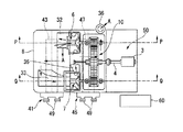
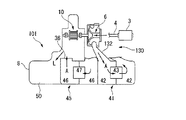
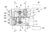
図1は、第一実施形態に係るターボ圧縮機1の概略構成を模式的に示す上面図(一部断面図)である。
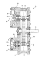
図2は、歯車装置10の構成を示す断面図である。
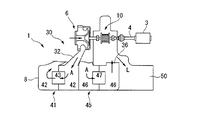
図3は、第一段圧縮機6を含む断面模式図(図1のP−P断面図)である。図4は、第二段圧縮機7を含む断面模式図(図1のQ−Q断面図)である。
Embodiments of a turbo compressor according to the present invention will be described below with reference to the drawings.
[First embodiment]
FIG. 1 is a top view (partially sectional view) schematically showing a schematic configuration of a turbo compressor 1 according to the first embodiment.
FIG. 2 is a cross-sectional view showing the configuration of the
FIG. 3 is a schematic cross-sectional view including the first stage compressor 6 (PP cross-sectional view in FIG. 1). FIG. 4 is a schematic cross-sectional view including the second stage compressor 7 (QQ cross-sectional view of FIG. 1).
ターボ圧縮機1は、駆動モータ3と、駆動モータ3の出力軸4に接続される歯車装置10と、歯車装置10により増速回転される第一羽根車21を有する第一段圧縮機6と、歯車装置10により増速回転される第二羽根車22を有する第二段圧縮機7と、これらの各構成要素を収容するケーシング8等を備えている。
The turbo compressor 1 includes a drive motor 3, a
ケーシング8には、外部から吸引した空気Aを第一段圧縮機6から第二段圧縮機7へと導き、更に第二段圧縮機7から外部へと導いて吐出すためのガス流路30が形成される。このガス流路30には、第一段圧縮機6で圧縮された空気Aを冷却するインタクーラ41と第二段圧縮機7で圧縮された空気Aを冷却するアフタクーラ45等が設けられている。
また、ケーシング8には、歯車装置10の潤滑させるオイルLを収容するオイル貯溜室50も設けられている。
In the
The
駆動モータ3は、歯車装置10を収容するギアケース9に不図示のフランジ等を介して取り付けられる。その出力軸4が歯車装置10の第一回転軸11に継手を介して接続されている。なお、ギアケース9は、ケーシング8に一体成型される。
なお、駆動モータ3は、ケーシング8に対して、ケーシング8の設置領域内に位置するように取り付けられる。つまり、ターボ圧縮機1を上面視すると、駆動モータ3がケーシング8から側方に突出させないようにしている。これにより、ターボ圧縮機1の設置面積がケーシング8の設置面積と略等しくなり、ターボ圧縮機装置1全体のコンパクト化が図られる。
The drive motor 3 is attached to a gear case 9 that houses the
The drive motor 3 is attached to the
図2に示すように、第一回転軸11は、ギアケース9に回転自在に支持されており、一端に軸受を介して駆動モータ3の出力軸4が連結され、他端側に大径の第一歯車14が取り付けられている。
第一歯車14は、第二回転軸12の一端に設けられた小径の第二歯車15と、第三回転軸13の一端に設けられた小径の第三歯車16と、にそれぞれ噛合されている。
そして、この歯車装置10により、駆動モータ3の出力軸4の回転が増速されて、第二回転軸12及び第三回転軸13にそれぞれ伝達されるようになっている。
As shown in FIG. 2, the first rotating
The
The
第二回転軸12及び第三回転軸13は、第一回転軸11に対して平行であり、且つ、第一回転軸11を挟んだ略対称な位置に、それぞれギアケース9に回転自在に軸支される。そして、第二回転軸12及び第三回転軸13の他端には、それぞれ第一羽根車21,第二羽根車22が設けられる。
第一羽根車21,第二羽根車22は、歯車装置10を挟んで駆動モータ3の反対側に配置される。つまり、第二回転軸12,第三回転軸13は、歯車装置10から駆動モータ3とは反対側延びるように支持されており、その一端(反駆動モータ側)に、第一羽根車21,第二羽根車22が配置されている。
The second
The
第一羽根車21は、ギアケース9の側部に形成された円柱状の窪部23に収容される。第二羽根車22は、ギアケース9の第一回転軸11を挟んだ反対側の側部に形成された円柱状の窪部24に収容される。
これら窪部23,24には、渦巻室および吸気通路31,34を有するブロック25,26がそれぞれ挿入され、ブロック25,26と窪部23,24との間にそれぞれディフューザが形成される。
なお、ギアケース9は、水平断面で上下に分割可能となっており、上部蓋を取り外すことで、第一〜第三回転軸11〜13、第一〜第三歯車14〜16の点検等が可能となっている。
The
In addition, the gear case 9 can be divided | segmented up and down in a horizontal cross section, and inspection of the 1st-3rd rotating shafts 11-13, the 1st-3rd gearwheels 14-16 is carried out by removing an upper cover. It is possible.
第一段圧縮機6、第二段圧縮機7及び歯車装置10の下方には、ギアケース9と一体的に鋳造された略直方体状の2つの空間(冷却室42,46)が形成されている。
一方の冷却室42には、第一段圧縮機6から吐出された空気Aを冷却して第二段圧縮機7へ導くインタクーラ41用の熱交換器43が設けられている。他方の冷却室46には、第二段圧縮機7から吐出された空気Aを冷却して排気するアフタクーラ45用の熱交換器47が設けられている。
Below the
One
熱交換器43,47は、各冷却室42,46の長手方向に沿って細長く形成され、冷却室42,46内の中央部に配置されて、冷却室42,46内をそれぞれ入口側と出口側とに仕切っている。
冷却室42,46には、入口側の長手方向の一端に導入口が、出口側の長手方向の他端に排出口が、それぞれ設けられている。
インタクーラ41の冷却室42の導入口は第一連絡通路32を介して第一段圧縮機6の渦巻室に接続され、排出口は第二連絡通路33を介して第二段圧縮機7の吸気通路34に接続される。
アフタクーラ45の冷却室46の導入口は第三連絡通路35を介して第二段圧縮機7の渦巻室に接続され、排出口はそれ自体が空気Aを外部に吐き出すための排気口36となっている。
なお、第一連絡通路32は、第一段圧縮機6の渦巻室から、第二回転軸12と略同一方向で斜め下方に向けて、冷却室42まで延設される。第二連絡通路33は、冷却室42から、第三回転軸13と略同一方向で斜め上方に向けて、第二段圧縮機7の吸気通路34まで延設される。第三連絡通路33は、第二段圧縮機6の渦巻室から、略下方に向けて、冷却室46まで延設される。
The
The cooling
The inlet of the cooling
The inlet of the cooling
The
熱交換器43,47は、その長手方向と直交して配置された複数のフィンプレート、これらフィンプレートを挿通して設けられた複数の水管と、フィンプレートの上下に設けられたシールバッフルと、シールバッフルに設けられたシール部材とを備えている(いずれも不図示)。
シールバッフルは、熱交換器43,47の一側面から他側面に空気Aを導くものであり、シール部材は、シールバッフルと冷却室42,46の内面との間をシールし、冷却室42,46内をそれぞれ入口側と出口側とに分けるものである。
また、熱交換器43,47は、上述した水管に冷却水を導入し、排出する冷却水出入口49をそれぞれ備える。冷却水出入口49は、熱交換器43,47の長手方向に一端に設けられる。
The
The seal baffle guides air A from one side of the
The
インタクーラ41,アフタクーラ45は、上方から見ると、歯車装置10の第一〜第三回転軸11〜13の軸方向に対して略直交する方向に沿って配置されている。また、駆動モータ3から離間する方向に向けて、アフタクーラ45、インタクーラ41の順に並んで配置されている。
そして、インタクーラ41,アフタクーラ45の熱交換器43,47のそれぞれの冷却水出入口49は、ターボ圧縮機1のケーシング8の同一側面に露出するように配置される。
When viewed from above, the
The cooling water inlet /
冷却室42,46の側方には、オイル貯溜室50が略平行に設けられている。オイル貯溜室50は、冷却室46の出口側(低温側)に隣接する。つまり、駆動モータ3から離間する方向に向けて、オイル貯溜室50、冷却室46(アフタクーラ45)、冷却室42(インタクーラ41)の順に並んで配置されている。
オイル貯溜室50には、歯車装置10の第一〜第三回転軸11〜13を支持する軸受や第一〜第三歯車14〜16を潤滑するためのオイルが貯溜されている。
オイル貯溜室50内には、不図示の潤滑油装置(オイルポンプ、オイル管、オイルクーラ等)が設けられており、オイルポンプにより汲み上げられ、オイルクーラにより冷却されたオイルが、オイル管を介して第一〜第三歯車14〜16に給油される。そして、給油されたオイルは、オイル貯溜室50に回収されるようになっている。
なお、オイル貯蔵室50の上部に、上述した潤滑油装置を設置してもよい。
On the side of the cooling
The
A lubricating oil device (not shown) (oil pump, oil pipe, oil cooler, etc.) is provided in the
Note that the above-described lubricating oil device may be installed in the upper part of the
2つの冷却室42,46、オイル貯溜室50は、ギアケース9と一体的に鋳造されて、ケーシング8を構成している。
そして、ケーシング8は、上方から見て略四角形状となって、ターボ圧縮機1の投影面積と一致する大きさに成形されている。
The two cooling
The
以上の構成からなるターボ圧縮機1では、第一段圧縮機6の第一羽根車21は、吸気通路31から空気Aを吸い込み、それを径方向外方に昇圧する。昇圧された空気Aは、ディフューザおよび渦巻室を通って減速されて速度が圧力に変換されることでさらに静圧が上昇して、第一連絡通路32を介してインタクーラ41に導かれる。そして、インタクーラ41で冷却された空気Aは、第二連絡通路33を介して第二段圧縮機7の吸気通路34に導かれる。
In the turbo compressor 1 having the above configuration, the
更に、第二段圧縮機7の第二羽根車22は、吸気通路34から空気Aを吸い込み、それを径方向外方に加速する。加速された空気Aは、ディフューザおよび渦巻室を通って減速されて速度が圧力に変換されて、第三連絡通路35を介してアフタクーラ45に導かれる。そして、アフタクーラ45で冷却された空気Aは、ケーシング8に形成された排気口36から外部(不図示の外部接続管)に吐き出される。
このようにして、ターボ圧縮機1では、所望量、所望圧力の空気Aを効率よく得られる。
Further, the
In this manner, the turbo compressor 1 can efficiently obtain air A having a desired amount and a desired pressure.
以上、説明したように、第一実施形態のターボ圧縮機1によれば、第一段圧縮機6の第一羽根車21と第二段圧縮機7の第二羽根車22とを異なる回転軸(第二回転軸12,第三回転軸13)に設けたので、第一羽根車21と第二羽根車22をそれぞれ最適な回転数で駆動できるので、高い効率で空気の圧縮処理を行うことができる。
As described above, according to the turbo compressor 1 of the first embodiment, the
また、インタクーラ41,アフタクーラ45は、上方から見ると、歯車装置10の第一〜第三回転軸11〜13の軸方向に対して略直交する方向に沿って配置されている。このため、最適なガス流路30が形成できる。つまり、ガス流路30(特に、第一連絡通路32、第二連絡通路33、第三連絡通路35)は、流路長さが短い、流路に大きな曲がり部分がない、また、鋳物として形成しやすい等の特徴を有している。
また、オイル貯溜室50を冷却室46の出口側(低温側)に隣接するように配置したので、オイルLが圧縮機で昇温された空気によって加熱されてしまう虞がない。
Further, the
Further, since the
また、インタクーラ41、アフタクーラ45、オイル貯溜室50を並べて配置したので、ターボ圧縮機1の設置面積が略四角形状となってコンパクトになっている。
また、インタクーラ41とアフタクーラ45は、それぞれのガス入口側(高温側)が隣接するように配置されているので、インタクーラ41により冷却されたガスがアフタクーラ45により加熱されたり、或いはアフタクーラ45により冷却されたガスがインタクーラ41により加熱されたりすることを防ぐことができる。
Further, since the
Further, since the
また、ターボ圧縮機1では、インタクーラ41,アフタクーラ45の熱交換器43,47のそれぞれの冷却水出入口49がケーシング8の同一側面に露出するように配置されているので、配管作業等が効率化できる。
なお、冷却水出入口49を第二圧縮機7側のケーシング8の側面に設けたが、第一圧縮機6側のケーシング8の側面に設けても良い。
また、ターボ圧縮機1の制御盤60を冷却水出入口49と同一の側面側に配置することで、メンテナンススペースを確保しやすくなる。
Further, in the turbo compressor 1, the cooling water inlets /
Although the cooling water inlet /
In addition, by arranging the
〔第二実施形態〕
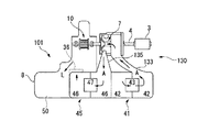
図5は、第二実施形態に係るターボ圧縮機101の概略構成を模式的に示す上面図(一部断面図)である。
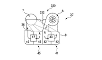
図6は、第一段圧縮機6を含む断面模式図(図5のP−P断面図)である。図7は、第二段圧縮機7を含む断面模式図(図5のQ−Q断面図)である。
[Second Embodiment]
FIG. 5 is a top view (partially sectional view) schematically showing a schematic configuration of the
FIG. 6 is a schematic cross-sectional view including the first stage compressor 6 (PP cross-sectional view in FIG. 5). FIG. 7 is a schematic cross-sectional view including the second stage compressor 7 (QQ cross-sectional view of FIG. 5).
ターボ圧縮機101は、第一実施形態に係るターボ圧縮機1と同一構成であるが、主要な構成要素の配置が異なっている。
以下の説明では、ターボ圧縮機1と異なる部分について説明し、同一の部分については同一の符号を付してその説明を省略する。
The
In the following description, parts different from the turbo compressor 1 will be described, and the same parts will be denoted by the same reference numerals and description thereof will be omitted.
ターボ圧縮機101は、ターボ圧縮機1と同様に、第一〜第三回転軸11〜13を備えている。第二回転軸12及び第三回転軸13は、第一回転軸11に対して平行であり、且つ、第一回転軸11を挟んだ対称な位置に、それぞれギアケース9に回転自在に軸支される。
そして、第二回転軸12及び第三回転軸13の他端には、それぞれ第一羽根車21,第二羽根車22が設けられる。第一羽根車21,第二羽根車22は、歯車装置10に対して駆動モータ3と同一側に配置される。つまり、第二回転軸12,第三回転軸13は、歯車装置10から駆動モータ3に向けて延びるように支持されており、その一端(駆動モータ側)に、第一羽根車21,第二羽根車22が配置されている。
As with the turbo compressor 1, the
And the
また、ターボ圧縮機101は、ターボ圧縮機1と同様に、インタクーラ41,アフタクーラ45は、上方から見ると、歯車装置10の第一〜第三回転軸11〜13の軸方向に対して略直交する方向に沿って配置されている。なお、駆動モータ3から離間する方向に向けて、インタクーラ41、アフタクーラ45の順に並んで配置されている。
そして、インタクーラ41,アフタクーラ45の熱交換器43,47のそれぞれの冷却水出入口49は、ターボ圧縮機1のケーシング8の同一側面に露出するように配置される。
Further, similarly to the turbo compressor 1, the
The cooling water inlet /
オイル貯溜室50は、冷却室42,46の側方に略平行に設けられている。オイル貯溜室50は、冷却室46の出口側(低温側)に隣接する。つまり、駆動モータ3から離間する方向に向けて、冷却室42(インタクーラ41)、冷却室46(アフタクーラ45)、オイル貯溜室50の順に並んで配置されている。
そして、2つの冷却室42,46、オイル貯溜室50は、ギアケース9と一体的に鋳造されて、ケーシング8を構成している。また、ケーシング8は、上方から見て略四角形状となって、ターボ圧縮機1の投影面積と一致する大きさに成形されている。
The
The two cooling
第二実施形態のターボ圧縮機101においても、第一段圧縮機6の第一羽根車21と第二段圧縮機7の第二羽根車22とを異なる回転軸(第二回転軸12,第三回転軸13)に設けたので、第一羽根車21と第二羽根車22をそれぞれ最適な回転数で駆動できるので、高い効率で空気の圧縮処理を行うことができる。
Also in the
また、ターボ圧縮機101においても、インタクーラ41,アフタクーラ45は、上方から見ると、歯車装置10の第一〜第三回転軸11〜13の軸方向に対して略直交する方向に沿って配置されているので、最適なガス流路130が形成できる。つまり、ガス流路130(特に、第一連絡通路132、第二連絡通路133、第三連絡通路135)は、流路長さが短い、流路に大きな曲がり部分がない、また、鋳物として形成しやすい等の特徴を有している。
なお、第一連絡通路132は、第一段圧縮機6の渦巻室から、第二回転軸12と略同一方向で斜め下方に向けて、冷却室42まで延設される。第二連絡通路133は、冷却室42から、第三回転軸13と略同一方向で斜め上方に向けて、第二段圧縮機7の吸気通路34まで延設される。第三連絡通路133は、第二段圧縮機6の渦巻室から、略下方に向けて、冷却室46まで延設される。
Also in the
The
また、オイル貯溜室50を冷却室46の出口側(低温側)に隣接するように配置したので、オイルLが圧縮機で昇温された空気によって加熱されてしまう虞がない。
また、インタクーラ41、アフタクーラ45、オイル貯溜室50を並べて配置したので、ターボ圧縮機1の設置面積が略四角形状となってコンパクトになっている。なお、オイル貯溜室50の上部に、第一段圧縮機6,第二段圧縮機7等が配置されないので、各種潤滑関連装置を設置することが可能となる。
また、インタクーラ41とアフタクーラ45は、それぞれのガス入口側(高温側)が隣接するように配置されているので、インタクーラ41により冷却されたガスがアフタクーラ45により加熱されたり、或いはアフタクーラ45により冷却されたガスがインタクーラ41により加熱されたりすることを防ぐことができる。
Further, since the
Further, since the
Further, since the
また、ターボ圧縮機101では、インタクーラ41,アフタクーラ45の熱交換器43,47のそれぞれの冷却水出入口49がケーシング8の同一側面に露出するように配置されているので、配管作業等が効率化できる。
なお、冷却水出入口を第二圧縮機側のケーシング側面に設けたが、第一圧縮機側のケーシング側面に設けても良い。
また、ターボ圧縮機101の制御盤60を冷却水出入口49と同一の側面側に配置することで、メンテナンススペースを確保しやすくなる。
また、オイル貯蔵室50の上部には関連部品が無いので、潤滑油装置を設置でき、ターボ圧縮機装置1の全体をコンパクトにすることができる。
Further, in the
In addition, although the cooling water inlet / outlet was provided in the casing side surface of the 2nd compressor side, you may provide it in the casing side surface of the 1st compressor side.
Further, by arranging the
Moreover, since there are no related parts in the upper part of the
〔第三実施形態〕
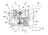
図8は、第三実施形態に係るターボ圧縮機201の概略構成を模式的に示す上面図(一部断面図)である。
図9は、第一段圧縮機6を含む断面模式図(図8のP−P断面図)である。図10は、第二段圧縮機7を含む断面模式図(図8のQ−Q断面図)である。
[Third embodiment]
FIG. 8 is a top view (partially sectional view) schematically showing a schematic configuration of the
FIG. 9 is a schematic cross-sectional view including the first-stage compressor 6 (PP cross-sectional view in FIG. 8). FIG. 10 is a schematic cross-sectional view including the second stage compressor 7 (QQ cross-sectional view of FIG. 8).
ターボ圧縮機201は、第一,第二実施形態に係るターボ圧縮機1,101と同一構成であるが、主要な構成要素の配置が異なっている。
以下の説明では、ターボ圧縮機1,101と異なる部分について説明し、同一の部分については同一の符号を付してその説明を省略する。
The
In the following description, portions different from the
ターボ圧縮機201は、ターボ圧縮機1,101と同様に、第一〜第三回転軸11〜13を備えている。第二回転軸12及び第三回転軸13は、第一回転軸11に対して平行であり、且つ、第一回転軸11を挟んだ対称な位置に、それぞれギアケース9に回転自在に軸支される。
そして、第二回転軸12及び第三回転軸13の他端には、それぞれ第一羽根車21,第二羽根車22が設けられる。第一羽根車21は、歯車装置10を挟んで駆動モータ3の反対側に配置される。一方、第二羽根車22は、歯車装置10に対して駆動モータ3と同一側に配置される。
つまり、第二回転軸12は、歯車装置10から駆動モータ3とは反対側延びるように支持されており、その一端(反駆動モータ側)に、第一羽根車21が配置されている。また、第三回転軸13は、歯車装置10から駆動モータ3に向けて延びるように支持されており、その一端(駆動モータ側)に、第二羽根車22が配置されている。
The
And the
In other words, the second
また、ターボ圧縮機201は、ターボ圧縮機1,101とは異なり、インタクーラ41,アフタクーラ45は、上方から見ると、歯車装置10の第一〜第三回転軸11〜13の軸方向に対して略平行する方向に沿って配置されている。なお、第二回転軸12(第一羽根車21)から離間する方向に向けて、インタクーラ41、アフタクーラ45の順に並んで配置されている。
そして、インタクーラ41,アフタクーラ45の熱交換器43,47のそれぞれの冷却水出入口49は、ターボ圧縮機1のケーシング8の同一側面(駆動モータ3の反対側)に露出するように配置される。
Further, the
The cooling water inlets /
オイル貯溜室50は、冷却室42,46の側方に設けられている。オイル貯溜室50は、冷却室42,46のそれぞれの冷却水出入口49とは反対側の側方に隣接する。つまり、駆動モータ3から離間する方向に向けて、オイル貯溜室50、冷却室42及び冷却室46(インタクーラ41及びアフタクーラ45)の順に並んで配置されている。
そして、2つの冷却室42,46、オイル貯溜室50は、ギアケース9と一体的に鋳造されて、ケーシング8を構成している。また、ケーシング8は、上方から見て略四角形状となって、ターボ圧縮機1の投影面積と一致する大きさに成形されている。
The
The two cooling
第三実施形態のターボ圧縮機201においても、第一段圧縮機6の第一羽根車21と第二段圧縮機7の第二羽根車22とを異なる回転軸(第二回転軸12,第三回転軸13)に設けたので、第一羽根車21と第二羽根車22をそれぞれ最適な回転数で駆動できるので、高い効率で空気の圧縮処理を行うことができる。
Also in the
また、ターボ圧縮機201においては、インタクーラ41,アフタクーラ45は、上方から見ると、歯車装置10の第一〜第三回転軸11〜13の軸方向に対して略平行する方向に沿って配置されているので、最適なガス流路230が形成できる。つまり、ガス流路230(特に、第一連絡通路232、第二連絡通路233、第三連絡通路235)は、流路長さが短い、流路に大きな曲がり部分がない、また、鋳物として形成しやすい等の特徴を有している。
なお、第一連絡通路232は、第一段圧縮機6の渦巻室から、略下方に向けて、冷却室42まで延設される。第二連絡通路233は、冷却室42から、第三回転軸13と略直交する方向で斜め上方に向けて、第二段圧縮機7の吸気通路34まで延設される。第三連絡通路233は、第二段圧縮機6の渦巻室から、略下方に向けて、冷却室46まで延設される。
In the
The
また、インタクーラ41、アフタクーラ45、オイル貯溜室50を最適に配置したので、ターボ圧縮機1の設置面積が略四角形状となってコンパクトになっている。
また、ターボ圧縮機201では、インタクーラ41,アフタクーラ45の熱交換器43,47のそれぞれの冷却水出入口49がケーシング8の同一側面に露出するように配置されているので、配管作業等が効率化できる。
また、インタクーラ41とアフタクーラ45は、それぞれのガス入口側(高温側)が隣接するように配置されているので、インタクーラ41により冷却されたガスがアフタクーラ45により加熱されたり、或いはアフタクーラ45により冷却されたガスがインタクーラ41により加熱されたりすることを防ぐことができる。
また、ターボ圧縮機201の制御盤60を、第一回転軸11を挟んだケーシング8の両側面のいずれにも配置することができるので、レイアウトの柔軟性が高くなっている。
In addition, since the
Further, in the
Further, since the
Further, since the
〔第四実施形態〕
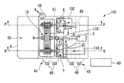
図11は、第四実施形態に係るターボ圧縮機301の概略構成を模式的に示す上面図(一部断面図)である。
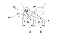
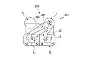
図12は、第一段圧縮機6を含む断面模式図(図11のP−P断面図)である。図13は、第二段圧縮機7を含む断面模式図(図11のQ−Q断面図)である。
[Fourth embodiment]
FIG. 11 is a top view (partially sectional view) schematically showing a schematic configuration of a
FIG. 12 is a schematic sectional view including the first stage compressor 6 (PP sectional view of FIG. 11). FIG. 13 is a schematic cross-sectional view including the second stage compressor 7 (QQ cross-sectional view of FIG. 11).
ターボ圧縮機301は、第一〜第三実施形態に係るターボ圧縮機1,101,201と同一構成であるが、主要な構成要素の配置が異なっている。
以下の説明では、ターボ圧縮機1,101,201と異なる部分について説明し、同一の部分については同一の符号を付してその説明を省略する。
The
In the following description, parts different from the
ターボ圧縮機301は、ターボ圧縮機1,101,201と同様に、第一〜第三回転軸11〜13を備えている。第二回転軸12及び第三回転軸13は、第一回転軸11に対して平行であり、且つ、第一回転軸11を挟んだ対称な位置に、それぞれギアケース9に回転自在に軸支される。
そして、第二回転軸12及び第三回転軸13の他端には、それぞれ第一羽根車21,第二羽根車22が設けられる。第一羽根車21は、歯車装置10に対して駆動モータ3と同一側に配置される。一方、第二羽根車22は、歯車装置10を挟んで駆動モータ3の反対側に配置される。
つまり、第二回転軸12は、歯車装置10から駆動モータ3に向けて延びるように支持されており、その一端(駆動モータ側)に、第一羽根車21が配置されている。また、第三回転軸13は、歯車装置10から駆動モータ3とは反対側延びるように支持されており、その一端(反駆動モータ側)に、第二羽根車22が配置されている。
The
And the
That is, the second
また、ターボ圧縮機301は、ターボ圧縮機201と同様に(ターボ圧縮機1,101とは異なり)、インタクーラ41,アフタクーラ45は、上方から見ると、歯車装置10の第一〜第三回転軸11〜13の軸方向に対して略平行する方向に沿って配置されている。なお、第二回転軸12(第一羽根車21)から離間する方向に向けて、インタクーラ41、アフタクーラ45の順に並んで配置されている。
そして、インタクーラ41,アフタクーラ45の熱交換器43,47のそれぞれの冷却水出入口49は、ターボ圧縮機1のケーシング8の同一側面(駆動モータ3の反対側)に露出するように配置される。
Further, the
The cooling water inlets /
オイル貯溜室50は、冷却室42,46の側方に設けられている。オイル貯溜室50は、冷却室42,46のそれぞれの冷却水出入口49とは反対側の側方に隣接する。つまり、駆動モータ3から離間する方向に向けて、オイル貯溜室50、冷却室42及び冷却室46(インタクーラ41及びアフタクーラ45)の順に並んで配置されている。
そして、2つの冷却室42,46、オイル貯溜室50は、ギアケース9と一体的に鋳造されて、ケーシング8を構成している。また、ケーシング8は、上方から見て略四角形状となって、ターボ圧縮機1の投影面積と一致する大きさに成形されている。
The
The two cooling
第四実施形態のターボ圧縮機301においても、第一段圧縮機6の第一羽根車21と第二段圧縮機7の第二羽根車22とを異なる回転軸(第二回転軸12,第三回転軸13)に設けたので、第一羽根車21と第二羽根車22をそれぞれ最適な回転数で駆動できるので、高い効率で空気の圧縮処理を行うことができる。
Also in the
また、ターボ圧縮機301においては、インタクーラ41,アフタクーラ45は、上方から見ると、歯車装置10の第一〜第三回転軸11〜13の軸方向に対して略平行する方向に沿って配置されているので、最適なガス流路330が形成できる。つまり、ガス流路330(特に、第一連絡通路332、第二連絡通路333、第三連絡通路335)は、流路長さが短い、流路に大きな曲がり部分がない、また、鋳物として形成しやすい等の特徴を有している。
なお、第一連絡通路232は、第一段圧縮機6の渦巻室から、略下方に向けて、冷却室42まで延設される。第二連絡通路233は、冷却室42から、第三回転軸13と略直交する方向で斜め上方に向けて、第二段圧縮機7の吸気通路34まで延設される。第三連絡通路233は、第二段圧縮機6の渦巻室から、略下方に向けて、冷却室46まで延設される。
Further, in the
The
また、インタクーラ41、アフタクーラ45、オイル貯溜室50を最適に配置したので、ターボ圧縮機1の設置面積が略四角形状となってコンパクトになっている。
また、ターボ圧縮機301では、インタクーラ41,アフタクーラ45の熱交換器43,47のそれぞれの冷却水出入口49がケーシング8の同一側面に露出するように配置されているので、配管作業等が効率化できる。
また、インタクーラ41とアフタクーラ45は、それぞれのガス入口側(高温側)が隣接するように配置されているので、インタクーラ41により冷却されたガスがアフタクーラ45により加熱されたり、或いはアフタクーラ45により冷却されたガスがインタクーラ41により加熱されたりすることを防ぐことができる。
また、ターボ圧縮機301の制御盤60を、第一回転軸11を挟んだケーシング8の両側面のいずれにも配置することができるので、レイアウトの柔軟性が高くなっている。
In addition, since the
Further, in the
Further, since the
Further, since the
なお、上述した実施の形態において示した各構成部材の諸形状や組み合わせ等は一例であって、本発明の主旨から逸脱しない範囲において設計要求等に基づき種々変更可能である。 The various shapes and combinations of the constituent members shown in the above-described embodiments are merely examples, and various modifications can be made based on design requirements and the like without departing from the gist of the present invention.
1,101,201,301…ターボ圧縮機
3…駆動モータ
6…第一段圧縮機
7…第二段圧縮機
8…ケーシング
10…歯車装置
11…第一回転軸
12…第二回転軸
13…第三回転軸
14…第一歯車
15…第二歯車
16…第三歯車
21…第一羽根車
22…第二羽根車
30,130,230,330…ガス流路
31…吸気通路
32,132,232,332…第一連絡通路
33,133,233,333…第二連絡通路
34…吸気通路
35,135,235,335…第三連絡通路
36…排気口
41…インタクーラ(第一冷却部)
42…冷却室
43…熱交換器
45…アフタクーラ(第二冷却部)
46…冷却室
47…熱交換器
49…冷却水出入口
50…オイル貯溜室
60…制御盤
A…空気(作動ガス)
L…オイル
DESCRIPTION OF SYMBOLS 1,101,201,301 ... Turbo compressor 3 ... Drive
42 ... Cooling
46 ... Cooling
L ... oil
Claims (11)
前記第一歯車に噛み合う第二歯車を有する第二回転軸と、
前記第二回転軸に取付けられた第一羽根車と、
前記第一歯車に噛み合う第三歯車を有すると共に前記第二回転軸に対して略平行に配置される第三回転軸と、
前記第三回転軸に取付けられた第二羽根車と、
前記第一羽根車で圧縮された作動ガスを冷却する第一冷却部と、
前記第二羽根車で圧縮された作動ガスを冷却する第二冷却部と、
前記第一乃至第三回転軸並びに前記第一及び第二冷却部を収容すると共に作動ガスを前記第一羽根車から前記第一冷却部及び前記第二羽根車を介して前記第二冷却部へと導くガス流路を有するケーシングと、
を備えるターボ圧縮機において、
前記第一及び第二羽根車を前記第一歯車に対して反駆動モータ側に配置し、且つ、前記第一及び第二冷却部を前記第一回転軸に対して略直交する方向に沿って配置したことを特徴とするターボ圧縮機。 A first rotating shaft connected to the output shaft of the drive motor and having a first gear;
A second rotating shaft having a second gear meshing with the first gear;
A first impeller attached to the second rotating shaft;
A third rotating shaft having a third gear meshing with the first gear and disposed substantially parallel to the second rotating shaft;
A second impeller attached to the third rotating shaft;
A first cooling section for cooling the working gas compressed by the first impeller;
A second cooling section for cooling the working gas compressed by the second impeller;
The first to third rotating shafts and the first and second cooling units are accommodated and working gas is transferred from the first impeller to the second cooling unit through the first cooling unit and the second impeller. A casing having a gas flow path leading to
In a turbo compressor comprising:
The first and second impellers are disposed on the side opposite to the driving motor with respect to the first gear, and the first and second cooling parts are along a direction substantially orthogonal to the first rotation axis. A turbo compressor characterized by being arranged.
前記第一歯車に噛み合う第二歯車を有する第二回転軸と、
前記第二回転軸に取付けられた第一羽根車と、
前記第一歯車に噛み合う第三歯車を有すると共に前記第二回転軸に対して略平行に配置される第三回転軸と、
前記第三回転軸に取付けられた第二羽根車と、
前記第一羽根車で圧縮された作動ガスを冷却する第一冷却部と、
前記第二羽根車で圧縮された作動ガスを冷却する第二冷却部と、
前記第一乃至第三回転軸並びに前記第一及び第二冷却部を収容すると共に作動ガスを前記第一羽根車から前記第一冷却部及び前記第二羽根車を介して前記第二冷却部へと導くガス流路を有するケーシングと、
を備えるターボ圧縮機において、
前記第一及び第二羽根車を前記第一歯車に対して駆動モータ側に配置し、且つ、前記第一及び第二冷却部を前記第一回転軸に対して略直交する方向に沿って配置したことを特徴とするターボ圧縮機。 A first rotating shaft connected to the output shaft of the drive motor and having a first gear;
A second rotating shaft having a second gear meshing with the first gear;
A first impeller attached to the second rotating shaft;
A third rotating shaft having a third gear meshing with the first gear and disposed substantially parallel to the second rotating shaft;
A second impeller attached to the third rotating shaft;
A first cooling section for cooling the working gas compressed by the first impeller;
A second cooling section for cooling the working gas compressed by the second impeller;
The first to third rotating shafts and the first and second cooling units are accommodated and working gas is transferred from the first impeller to the second cooling unit through the first cooling unit and the second impeller. A casing having a gas flow path leading to
In a turbo compressor comprising:
The first and second impellers are arranged on the drive motor side with respect to the first gear, and the first and second cooling parts are arranged along a direction substantially orthogonal to the first rotation axis. A turbo compressor characterized by that.
前記第一歯車に噛み合う第二歯車を有する第二回転軸と、
前記第二回転軸に取付けられた第一羽根車と、
前記第一歯車に噛み合う第三歯車を有すると共に前記第二回転軸に対して略平行に配置される第三回転軸と、
前記第三回転軸に取付けられた第二羽根車と、
前記第一羽根車で圧縮された作動ガスを冷却する第一冷却部と、
前記第二羽根車で圧縮された作動ガスを冷却する第二冷却部と、
前記第一乃至第三回転軸並びに前記第一及び第二冷却部を収容すると共に作動ガスを前記第一羽根車から前記第一冷却部及び前記第二羽根車を介して前記第二冷却部へと導くガス流路を有するケーシングと、
を備えるターボ圧縮機において、
前記第一羽根車を前記第一歯車に対して反駆動モータ側に、前記第二羽根車を駆動モータ側に配置し、且つ、前記第一及び第二冷却部を前記第一回転軸に対して略平行する方向に沿って配置したことを特徴とするターボ圧縮機。 A first rotating shaft connected to the output shaft of the drive motor and having a first gear;
A second rotating shaft having a second gear meshing with the first gear;
A first impeller attached to the second rotating shaft;
A third rotating shaft having a third gear meshing with the first gear and disposed substantially parallel to the second rotating shaft;
A second impeller attached to the third rotating shaft;
A first cooling section for cooling the working gas compressed by the first impeller;
A second cooling section for cooling the working gas compressed by the second impeller;
The first to third rotating shafts and the first and second cooling units are accommodated and working gas is transferred from the first impeller to the second cooling unit through the first cooling unit and the second impeller. A casing having a gas flow path leading to
In a turbo compressor comprising:
The first impeller is disposed on the side opposite to the drive motor with respect to the first gear, the second impeller is disposed on the drive motor side, and the first and second cooling portions are disposed on the first rotation shaft. The turbo compressor is arranged along a substantially parallel direction.
前記第一歯車に噛み合う第二歯車を有する第二回転軸と、
前記第二回転軸に取付けられた第一羽根車と、
前記第一歯車に噛み合う第三歯車を有すると共に前記第二回転軸に対して略平行に配置される第三回転軸と、
前記第三回転軸に取付けられた第二羽根車と、
前記第一羽根車で圧縮された作動ガスを冷却する第一冷却部と、
前記第二羽根車で圧縮された作動ガスを冷却する第二冷却部と、
前記第一乃至第三回転軸並びに前記第一及び第二冷却部を収容すると共に作動ガスを前記第一羽根車から前記第一冷却部及び前記第二羽根車を介して前記第二冷却部へと導くガス流路を有するケーシングと、
を備えるターボ圧縮機において、
前記第一羽根車を前記第一歯車に対して駆動モータ側に、前記第二羽根車を反駆動モータ側に配置し、且つ、前記第一及び第二冷却部を前記第一回転軸に対して略平行する方向に沿って配置したことを特徴とするターボ圧縮機。 A first rotating shaft connected to the output shaft of the drive motor and having a first gear;
A second rotating shaft having a second gear meshing with the first gear;
A first impeller attached to the second rotating shaft;
A third rotating shaft having a third gear meshing with the first gear and disposed substantially parallel to the second rotating shaft;
A second impeller attached to the third rotating shaft;
A first cooling section for cooling the working gas compressed by the first impeller;
A second cooling section for cooling the working gas compressed by the second impeller;
The first to third rotating shafts and the first and second cooling units are accommodated and working gas is transferred from the first impeller to the second cooling unit through the first cooling unit and the second impeller. A casing having a gas flow path leading to
In a turbo compressor comprising:
The first impeller is disposed on the drive motor side with respect to the first gear, the second impeller is disposed on the counter drive motor side, and the first and second cooling units are disposed on the first rotation shaft. The turbo compressor is arranged along a substantially parallel direction.
Priority Applications (1)
| Application Number | Priority Date | Filing Date | Title |
|---|---|---|---|
| JP2006318823A JP4876868B2 (en) | 2006-11-27 | 2006-11-27 | Turbo compressor |
Applications Claiming Priority (1)
| Application Number | Priority Date | Filing Date | Title |
|---|---|---|---|
| JP2006318823A JP4876868B2 (en) | 2006-11-27 | 2006-11-27 | Turbo compressor |
Publications (2)
| Publication Number | Publication Date |
|---|---|
| JP2008133746A JP2008133746A (en) | 2008-06-12 |
| JP4876868B2 true JP4876868B2 (en) | 2012-02-15 |
Family
ID=39558768
Family Applications (1)
| Application Number | Title | Priority Date | Filing Date |
|---|---|---|---|
| JP2006318823A Expired - Fee Related JP4876868B2 (en) | 2006-11-27 | 2006-11-27 | Turbo compressor |
Country Status (1)
| Country | Link |
|---|---|
| JP (1) | JP4876868B2 (en) |
Cited By (2)
| Publication number | Priority date | Publication date | Assignee | Title |
|---|---|---|---|---|
| WO2018137019A1 (en) * | 2017-01-27 | 2018-08-02 | S. A. Armstrong Limited | Dual body variable duty performance optimizing pump unit |
| US20180283389A1 (en) * | 2015-09-02 | 2018-10-04 | Kabushiki Kaisha Kobe Seiko Sho (Kobe Steel, Ltd.) | Compressor |
Families Citing this family (5)
| Publication number | Priority date | Publication date | Assignee | Title |
|---|---|---|---|---|
| JP2010275939A (en) * | 2009-05-29 | 2010-12-09 | Hitachi Industrial Equipment Systems Co Ltd | Water-cooled oil-free air compressor |
| JP5616866B2 (en) * | 2011-09-13 | 2014-10-29 | 株式会社神戸製鋼所 | Turbo compressor |
| JP6002485B2 (en) * | 2012-07-13 | 2016-10-05 | 株式会社日立製作所 | Multistage centrifugal compressor |
| JP6079144B2 (en) * | 2012-11-01 | 2017-02-15 | 株式会社Ihi | Carbon dioxide recovery device |
| JP6472373B2 (en) | 2015-12-22 | 2019-02-20 | 株式会社神戸製鋼所 | Screw compressor |
Family Cites Families (8)
| Publication number | Priority date | Publication date | Assignee | Title |
|---|---|---|---|---|
| JPS5523428A (en) * | 1978-08-08 | 1980-02-19 | Kogaku Kogyo Gijutsu Kenkyu Kumiai | Mtf measuring instrument for lens |
| JP3480009B2 (en) * | 1993-10-04 | 2003-12-15 | 石川島播磨重工業株式会社 | Centrifugal compressor |
| JP3470410B2 (en) * | 1994-09-28 | 2003-11-25 | 石川島播磨重工業株式会社 | Turbo compressor |
| JP2000104698A (en) * | 1998-09-28 | 2000-04-11 | Kobe Steel Ltd | Compressor |
| JP2001289199A (en) * | 2000-04-10 | 2001-10-19 | Kobe Steel Ltd | Turbo compressor |
| JP4082009B2 (en) * | 2001-09-25 | 2008-04-30 | 株式会社日立プラントテクノロジー | Turbo compressor |
| JP4048078B2 (en) * | 2002-05-17 | 2008-02-13 | 株式会社神戸製鋼所 | Turbo compressor |
| JP2007332826A (en) * | 2006-06-13 | 2007-12-27 | Kobe Steel Ltd | Centrifugal compressor |
-
2006
- 2006-11-27 JP JP2006318823A patent/JP4876868B2/en not_active Expired - Fee Related
Cited By (3)
| Publication number | Priority date | Publication date | Assignee | Title |
|---|---|---|---|---|
| US20180283389A1 (en) * | 2015-09-02 | 2018-10-04 | Kabushiki Kaisha Kobe Seiko Sho (Kobe Steel, Ltd.) | Compressor |
| US10641275B2 (en) * | 2015-09-02 | 2020-05-05 | Kobe Steel, Ltd. | Compressor |
| WO2018137019A1 (en) * | 2017-01-27 | 2018-08-02 | S. A. Armstrong Limited | Dual body variable duty performance optimizing pump unit |
Also Published As
| Publication number | Publication date |
|---|---|
| JP2008133746A (en) | 2008-06-12 |
Similar Documents
| Publication | Publication Date | Title |
|---|---|---|
| KR100487591B1 (en) | Turbo compressor | |
| CN1232733C (en) | Helical-lobe compressor | |
| CN100520071C (en) | Screw compressor | |
| US7832992B2 (en) | Air cooled packaged multi-stage centrifugal compressor system | |
| JP5616866B2 (en) | Turbo compressor | |
| JP5774455B2 (en) | Oil-free compressor | |
| JP2007332826A (en) | Centrifugal compressor | |
| WO2013021664A1 (en) | Centrifugal compressor | |
| KR101316975B1 (en) | Multi-stage centrifugal compressor | |
| JP4876868B2 (en) | Turbo compressor | |
| JP6607960B2 (en) | Gas compressor | |
| JP3470410B2 (en) | Turbo compressor | |
| KR102036201B1 (en) | Turbo Compressor | |
| JP6002485B2 (en) | Multistage centrifugal compressor | |
| US20110171015A1 (en) | Centrifugal compressor and fabricating method thereof | |
| JP7267798B2 (en) | Compressor and shell-and-tube heat exchanger | |
| JP5160609B2 (en) | Compressor unit | |
| JP2013011174A (en) | Turbocompressor | |
| CN221144790U (en) | Centrifugal air compressor | |
| JP2004308477A (en) | Turbo compressor and packaging method thereof | |
| CN114754002A (en) | Multipurpose screw rod unit |
Legal Events
| Date | Code | Title | Description |
|---|---|---|---|
| A621 | Written request for application examination |
Free format text: JAPANESE INTERMEDIATE CODE: A621 Effective date: 20090928 |
|
| A977 | Report on retrieval |
Free format text: JAPANESE INTERMEDIATE CODE: A971007 Effective date: 20111026 |
|
| TRDD | Decision of grant or rejection written | ||
| A01 | Written decision to grant a patent or to grant a registration (utility model) |
Free format text: JAPANESE INTERMEDIATE CODE: A01 Effective date: 20111101 |
|
| A01 | Written decision to grant a patent or to grant a registration (utility model) |
Free format text: JAPANESE INTERMEDIATE CODE: A01 |
|
| A61 | First payment of annual fees (during grant procedure) |
Free format text: JAPANESE INTERMEDIATE CODE: A61 Effective date: 20111114 |
|
| R151 | Written notification of patent or utility model registration |
Ref document number: 4876868 Country of ref document: JP Free format text: JAPANESE INTERMEDIATE CODE: R151 |
|
| FPAY | Renewal fee payment (event date is renewal date of database) |
Free format text: PAYMENT UNTIL: 20141209 Year of fee payment: 3 |
|
| S111 | Request for change of ownership or part of ownership |
Free format text: JAPANESE INTERMEDIATE CODE: R313111 |
|
| R350 | Written notification of registration of transfer |
Free format text: JAPANESE INTERMEDIATE CODE: R350 |
|
| R250 | Receipt of annual fees |
Free format text: JAPANESE INTERMEDIATE CODE: R250 |
|
| LAPS | Cancellation because of no payment of annual fees |