JP2013080144A5 - - Google Patents
Download PDFInfo
- Publication number
- JP2013080144A5 JP2013080144A5 JP2011220773A JP2011220773A JP2013080144A5 JP 2013080144 A5 JP2013080144 A5 JP 2013080144A5 JP 2011220773 A JP2011220773 A JP 2011220773A JP 2011220773 A JP2011220773 A JP 2011220773A JP 2013080144 A5 JP2013080144 A5 JP 2013080144A5
- Authority
- JP
- Japan
- Prior art keywords
- image
- acquisition device
- image acquisition
- multiple exposure
- range
- Prior art date
- Legal status (The legal status is an assumption and is not a legal conclusion. Google has not performed a legal analysis and makes no representation as to the accuracy of the status listed.)
- Granted
Links
Images
Description
ステージ11は、撮像対象である例えば組織切片、細胞又は染色体等の生体サンプルSPLを配置可能な面を有する。ステージ11は、その面に対して平行方向(xy軸方向)及び直交方向(z軸方向)に移動自在に構成される。
なお、生体サンプルSPLは、この実施形態ではスライドガラスSGに対して所定の固定手法により固定され、必要に応じて染色が施される。この染色には、HE(Hematoxylin-Eosin)染色、ギムザ染色又はパパニコロウ染色等に代表される一般染色のみならず、FISH(Fluorescence In-Situ Hybridization)や酵素抗体法等の蛍光染色が含まれる。
The stage 11 has a surface on which a biological sample SPL such as a tissue section, a cell, or a chromosome to be imaged can be placed. The stage 11 is configured to be movable in a parallel direction (xy axis direction ) and an orthogonal direction (z axis direction) with respect to the surface.
In this embodiment, the biological sample SPL is fixed to the slide glass SG by a predetermined fixing method, and is stained as necessary. This staining includes not only general staining represented by HE (Hematoxylin-Eosin) staining, Giemsa staining or Papanicolaou staining, but also fluorescence staining such as FISH (Fluorescence In-Situ Hybridization) and enzyme antibody method.
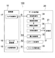
データ処理部20は、顕微鏡10のカメラ制御部17より供給されるRAWデータの現像処理、現像データのスティッチング処理などを行って生体サンプル画像を生成し、これをJPEG(Joint Photographic Experts Group)など所定の圧縮形式のデータに符号化して保存する。また、データ処理部20は、所定のプログラムに基づいて光源駆動部15、ステージ駆動部16及びカメラ制御部17をそれぞれ制御するための演算処理を実行する。
The
CPU21は、生体サンプルSPLの画像の取得命令に対応するプログラムに従って、図5に示すように、ステージ制御部31(移動制御部)、露光制御部32(多重露光処理部)、ストロボ制御部33(多重露光処理部)、画像取得部34、現像処理部35、画像圧縮部36及び画像記録部37として機能する。
As shown in FIG. 5, the CPU 21 follows a program corresponding to an image acquisition command for the biological sample SPL, as shown in FIG. 5, a stage control unit 31 (movement control unit), an exposure control unit 32 (multiple exposure processing unit), and a strobe control unit 33 ( Multiple exposure processing unit),
図12は4μmの範囲の平均画像のデフォーカス特性を示すグラフである。点線で示す線は固定焦点画像のデフォーカス特性であり、その他の複数の実線はそれぞれ4μmの範囲の平均画像のデフォーカス特性である。すなわち、平均画像Aは合焦位置からこの合焦位置より下に4μmまでの範囲の平均画像、平均画像Bは合焦位置からこの合焦位置より上に4μmまでの範囲の平均画像、平均画像Cは合焦位置より下に3μmの位置から合焦位置より上に1μmまでの範囲の平均画像、平均画像Dは合焦位置より下に1μmの位置から合焦位置より上に3μmまでの範囲の平均画像、平均画像Eは合焦位置より上に2μmの位置から合焦位置より下に2μmまでの範囲の平均画像Eである。平均画像Aと平均画像Bのデフォーカス特性はほぼ同じであるため、これらは1つの実線で示した。同様に平均画像Cと平均画像Dのデフォーカス特性はほぼ同じであるため、これらも1つの実線で示した。 FIG. 12 is a graph showing the defocus characteristics of an average image in the range of 4 μm. A line indicated by a dotted line is a defocus characteristic of the fixed focus image, and a plurality of other solid lines are defocus characteristics of an average image in a range of 4 μm. That is, the average image A is an average image in the range from the in-focus position to 4 μm below the in-focus position, and the average image B is the average image and average image in the range from the in-focus position to 4 μm above the in-focus position. C is an average image in a range from 3 μm below the in-focus position to 1 μm above the in- focus position, and average image D is in a range from 1 μm below the in-focus position to 3 μm above the in-focus position. The average image E and the average image E are average images E ranging from a position 2 μm above the in-focus position to 2 μm below the in-focus position. Since the defocus characteristics of the average image A and the average image B are almost the same, they are shown by one solid line. Similarly, since the defocus characteristics of the average image C and the average image D are almost the same, these are also shown by one solid line.
<変形例3>
図15はZスタックの撮像時の動作の変形例3を示すタイミングチャートである。
変形例3の画像取得装置は、連続する複数の焦点位置に跨って撮像素子14を連続的に露光させる間、光源ユニット13の光照射のオンとオフを焦点位置の間隔よりも短い一定の周期で繰り返し切り替えるようにしたものである。この変形例3によっても、上記の実施形態の画像処理装置100および変形例2の画像取得装置の効果を同様に得ることができる。また、本変形例3によれば、光照射のオンデューティ比の選択により露光時間を調整することが可能である。
<Modification 3>
FIG. 15 is a timing chart showing a third modification example of the operation during imaging of the Z stack.
In the image acquisition device of the third modification, while the image sensor 14 is continuously exposed across a plurality of continuous focal positions, the light irradiation of the light source unit 13 is turned on and off at a constant cycle shorter than the focal position interval. It is made to switch repeatedly. Also in the third modification, the effects of the
Claims (7)
前記光学系により拡大される前記部位を結像する全画素同時露光が可能な撮像素子と、
前記撮像対象の部位の厚さ方向に前記対物レンズの焦点を移動させる移動制御部と、
前記焦点を移動させることが可能な方向の位置によって区分される範囲毎に、当該範囲を網羅する平均画像が得られるように撮像素子を複数の位置で多重露光させる多重露光処理部と
を具備する画像取得装置。 An optical system including an objective lens for enlarging a region to be imaged;
An image pickup device capable of simultaneous exposure of all pixels for forming an image of the portion enlarged by the optical system;
A movement control unit that moves the focal point of the objective lens in the thickness direction of the region to be imaged; and
A multiple exposure processing unit that performs multiple exposure of the image sensor at a plurality of positions so that an average image covering the range is obtained for each range divided by positions in a direction in which the focus can be moved. Image acquisition device.
前記範囲の長さは、前記光学系の焦点深度に前記露光の多重数を乗じた値以下である
画像取得装置。 The image acquisition device according to claim 1,
The length of the range is an image acquisition device that is not more than a value obtained by multiplying the depth of focus of the optical system by the number of multiple exposures.
前記多重露光処理部は、前記対物レンズの焦点位置を移動させながら前記撮像素子を多重露光させる
画像取得装置。 The image acquisition device according to claim 1 or 2,
The multiple exposure processing unit is an image acquisition device that performs multiple exposure of the image sensor while moving a focal position of the objective lens.
前記多重露光処理部は、前記複数の位置に跨って前記撮像素子を連続的に露光させる
画像取得装置。 The image acquisition device according to claim 1 or 2 ,
The multiple exposure processing unit is an image acquisition device that continuously exposes the image sensor across the plurality of positions.
前記範囲毎の前記連続的に露光させる位置が、それぞれの前記範囲間で連続する
画像取得装置。 The image acquisition device according to claim 4,
The image acquisition device in which the continuously exposed positions for each of the ranges are continuous between the ranges.
多重露光処理部が、前記焦点を移動させることが可能な方向の位置によって区分される範囲毎に、当該範囲を網羅する平均画像が得られるように撮像素子を複数の位置で多重露光させる
画像取得方法。 The movement control unit moves the focal point of the objective lens in the thickness direction of the site to be observed,
Image acquisition is performed by the multiple exposure processing unit for each range divided by the position in the direction in which the focal point can be moved, and the image sensor is subjected to multiple exposure so that an average image covering the range is obtained. Method.
前記光学系により拡大される前記部位を結像する全画素同時露光が可能な撮像素子とを具備する顕微鏡を制御するコンピュータを動作させるプログラムであって、
前記撮像対象の部位の厚さ方向に前記対物レンズの焦点を移動させる移動制御部と、
前記焦点を移動させることが可能な方向の位置によって区分される範囲毎に、当該範囲を網羅する平均画像が得られるように撮像素子を複数の位置で多重露光させる多重露光処理部として前記コンピュータを動作させるプログラム。 An optical system including an objective lens for enlarging a region to be imaged;
A program for operating a computer that controls a microscope having an image pickup device capable of simultaneous exposure of all pixels that forms an image of the portion magnified by the optical system,
A movement control unit that moves the focal point of the objective lens in the thickness direction of the region to be imaged; and
The computer is used as a multiple exposure processing unit for performing multiple exposure of the image sensor at a plurality of positions so that an average image covering the range is obtained for each range divided by the position in the direction in which the focus can be moved. The program to be run.
Priority Applications (3)
| Application Number | Priority Date | Filing Date | Title |
|---|---|---|---|
| JP2011220773A JP6136085B2 (en) | 2011-10-05 | 2011-10-05 | Image acquisition apparatus, image acquisition method, and computer program |
| US13/617,418 US9386233B2 (en) | 2011-10-05 | 2012-09-14 | Image acquisition apparatus, image acquisition method, and computer program |
| CN201210362291XA CN103033921A (en) | 2011-10-05 | 2012-09-25 | Image acquisition apparatus, image acquisition method, and computer program |
Applications Claiming Priority (1)
| Application Number | Priority Date | Filing Date | Title |
|---|---|---|---|
| JP2011220773A JP6136085B2 (en) | 2011-10-05 | 2011-10-05 | Image acquisition apparatus, image acquisition method, and computer program |
Related Child Applications (1)
| Application Number | Title | Priority Date | Filing Date |
|---|---|---|---|
| JP2017000182A Division JP2017058704A (en) | 2017-01-04 | 2017-01-04 | Image acquisition device, image acquisition method, and computer program |
Publications (3)
| Publication Number | Publication Date |
|---|---|
| JP2013080144A JP2013080144A (en) | 2013-05-02 |
| JP2013080144A5 true JP2013080144A5 (en) | 2014-11-06 |
| JP6136085B2 JP6136085B2 (en) | 2017-05-31 |
Family
ID=48020970
Family Applications (1)
| Application Number | Title | Priority Date | Filing Date |
|---|---|---|---|
| JP2011220773A Expired - Fee Related JP6136085B2 (en) | 2011-10-05 | 2011-10-05 | Image acquisition apparatus, image acquisition method, and computer program |
Country Status (3)
| Country | Link |
|---|---|
| US (1) | US9386233B2 (en) |
| JP (1) | JP6136085B2 (en) |
| CN (1) | CN103033921A (en) |
Families Citing this family (10)
| Publication number | Priority date | Publication date | Assignee | Title |
|---|---|---|---|---|
| US20150301328A1 (en) * | 2012-11-16 | 2015-10-22 | Molecular Devices, Llc | System and method of acquiring images with a rolling shutter camera while asynchronously sequencing microscope devices |
| JP6134249B2 (en) * | 2013-11-01 | 2017-05-24 | 浜松ホトニクス株式会社 | Image acquisition device and image acquisition method of image acquisition device |
| WO2017098587A1 (en) * | 2015-12-08 | 2017-06-15 | オリンパス株式会社 | Microscopic observation system, microscopic observation method, and microscopic observation program |
| WO2018042629A1 (en) * | 2016-09-02 | 2018-03-08 | オリンパス株式会社 | Image observation device and microscope system |
| JP6715463B2 (en) * | 2016-09-30 | 2020-07-01 | パナソニックIpマネジメント株式会社 | Image generating apparatus, image generating method, program and recording medium |
| DE102017108016A1 (en) * | 2017-04-13 | 2018-10-18 | Carl Zeiss Microscopy Gmbh | Microscope system and method for operating a microscope system |
| DE102017123510A1 (en) * | 2017-10-10 | 2019-04-11 | Carl Zeiss Microscopy Gmbh | Digital microscope and method for picking up a stack of microscopic images of a sample |
| US10812701B2 (en) | 2018-12-13 | 2020-10-20 | Mitutoyo Corporation | High-speed tag lens assisted 3D metrology and extended depth-of-field imaging |
| CN110076989B (en) * | 2019-05-22 | 2024-04-05 | 华南理工大学 | Printing method of 3D printing device based on nonlinear focusing multi-partition exposure |
| CN115629505B (en) * | 2022-12-06 | 2023-03-28 | 开拓导航控制技术股份有限公司 | Liquid crystal regulation-based real-time inhibition method and system for overexposure in imaging process |
Family Cites Families (18)
| Publication number | Priority date | Publication date | Assignee | Title |
|---|---|---|---|---|
| JP3191928B2 (en) * | 1988-02-23 | 2001-07-23 | オリンパス光学工業株式会社 | Image input / output device |
| DE3905619C2 (en) * | 1988-02-23 | 2000-04-13 | Olympus Optical Co | Image input / output device |
| JPH04308975A (en) * | 1991-04-05 | 1992-10-30 | Taiyo Densan Kk | Method and device for image recording by camera |
| GB2383487B (en) * | 2001-12-18 | 2006-09-27 | Fairfield Imaging Ltd | Method and apparatus for acquiring digital microscope images |
| JP5134365B2 (en) | 2004-05-27 | 2013-01-30 | アペリオ・テクノロジーズ・インコーポレイテッド | System and method for generating and visualizing a three-dimensional virtual slide |
| JP4311668B2 (en) * | 2004-11-15 | 2009-08-12 | オリンパス株式会社 | Imaging apparatus, imaging system, and image capturing method |
| US8422127B2 (en) * | 2005-03-17 | 2013-04-16 | Hamamatsu Photonics K.K. | Microscopic image capturing device |
| JP2008011298A (en) * | 2006-06-30 | 2008-01-17 | Fujitsu Ltd | Solid-state imaging apparatus and control method therefor |
| WO2008076191A2 (en) * | 2006-12-15 | 2008-06-26 | Exxonmobil Upstream Research Company | Identification and suppression of multiples in ocean bottom seismic data |
| WO2008137746A1 (en) * | 2007-05-04 | 2008-11-13 | Aperio Technologies, Inc. | Rapid microscope scanner for volume image acquisition |
| US8724013B2 (en) * | 2007-12-27 | 2014-05-13 | Qualcomm Incorporated | Method and apparatus with fast camera auto focus |
| JP5090188B2 (en) * | 2008-01-10 | 2012-12-05 | オリンパス株式会社 | Microscope equipment |
| JP5257375B2 (en) * | 2009-03-13 | 2013-08-07 | オムロン株式会社 | Image processing apparatus and image processing method |
| JP5499732B2 (en) * | 2009-06-23 | 2014-05-21 | ソニー株式会社 | Biological sample image acquisition apparatus, biological sample image acquisition method, and biological sample image acquisition program |
| US8310531B2 (en) * | 2009-08-03 | 2012-11-13 | Genetix Corporation | Methods and apparatuses for processing fluorescence images |
| JP5497386B2 (en) * | 2009-09-11 | 2014-05-21 | 浜松ホトニクス株式会社 | Image acquisition device |
| US8581162B2 (en) * | 2009-12-08 | 2013-11-12 | Mitutoyo Corporation | Weighting surface fit points based on focus peak uncertainty |
| JP2011180442A (en) * | 2010-03-02 | 2011-09-15 | Sony Corp | Device, method and program for acquisition of sample image |
-
2011
- 2011-10-05 JP JP2011220773A patent/JP6136085B2/en not_active Expired - Fee Related
-
2012
- 2012-09-14 US US13/617,418 patent/US9386233B2/en active Active
- 2012-09-25 CN CN201210362291XA patent/CN103033921A/en active Pending
Similar Documents
| Publication | Publication Date | Title |
|---|---|---|
| JP2013080144A5 (en) | ||
| JP5212122B2 (en) | Biological sample image acquisition apparatus, biological sample image acquisition method, and program | |
| JP6136085B2 (en) | Image acquisition apparatus, image acquisition method, and computer program | |
| JP6143098B2 (en) | Objective lens drive control method and fluorescence microscope system | |
| JP2007233098A (en) | Image acquisition device, image acquisition method, and image acquisition program | |
| JP2011059515A (en) | Image acquisition device | |
| US20180275389A1 (en) | Remote Focusing All-Optical Digital Scanning Light Sheet Microscopy for Optically Cleared Tissue Sections | |
| TWI811758B (en) | Deep learning model for auto-focusing microscope systems, method of automatically focusing a microscope system, and non-transitory computer readable medium | |
| JP6940696B2 (en) | Two-dimensional and three-dimensional fixed Z-scan | |
| JP6327829B2 (en) | Microscope control apparatus, microscope system, control method, and program | |
| JP6157155B2 (en) | Microscope system, driving method and program | |
| WO2018042786A1 (en) | Image processing method, image processing device, and imaging device | |
| WO2014087713A1 (en) | Image capture device and microscope system | |
| US20210149170A1 (en) | Method and apparatus for z-stack acquisition for microscopic slide scanner | |
| US20170278259A1 (en) | Microscope system and specimen observation method | |
| TWI677706B (en) | Microscopic device and autofocus method | |
| JP2014178403A (en) | Digital microscope system, information processing method and information processing program | |
| JP2014085599A (en) | Microscope | |
| WO2015004968A1 (en) | Image acquisition device and image acquisition method | |
| JP2017058704A (en) | Image acquisition device, image acquisition method, and computer program | |
| JP6378869B2 (en) | Microscope, microscope system, control method and program | |
| JP2010091739A (en) | Image pickup device including automatic focusing device | |
| JP2018116309A (en) | Image acquisition device, image acquisition method, and microscope | |
| JP5581785B2 (en) | Microscope, position control method, and position control program | |
| JP2023078801A (en) | Microscope system and microscope control device |