JP2013061530A - Catadioptric system and imaging apparatus having the same - Google Patents
Catadioptric system and imaging apparatus having the same Download PDFInfo
- Publication number
- JP2013061530A JP2013061530A JP2011200546A JP2011200546A JP2013061530A JP 2013061530 A JP2013061530 A JP 2013061530A JP 2011200546 A JP2011200546 A JP 2011200546A JP 2011200546 A JP2011200546 A JP 2011200546A JP 2013061530 A JP2013061530 A JP 2013061530A
- Authority
- JP
- Japan
- Prior art keywords
- optical element
- image
- catadioptric
- optical system
- light
- Prior art date
- Legal status (The legal status is an assumption and is not a legal conclusion. Google has not performed a legal analysis and makes no representation as to the accuracy of the status listed.)
- Withdrawn
Links
Images


Classifications
-
- G—PHYSICS
- G02—OPTICS
- G02B—OPTICAL ELEMENTS, SYSTEMS OR APPARATUS
- G02B17/00—Systems with reflecting surfaces, with or without refracting elements
- G02B17/08—Catadioptric systems
- G02B17/0884—Catadioptric systems having a pupil corrector
- G02B17/0888—Catadioptric systems having a pupil corrector the corrector having at least one aspheric surface, e.g. Schmidt plates
-
- G—PHYSICS
- G02—OPTICS
- G02B—OPTICAL ELEMENTS, SYSTEMS OR APPARATUS
- G02B13/00—Optical objectives specially designed for the purposes specified below
- G02B13/18—Optical objectives specially designed for the purposes specified below with lenses having one or more non-spherical faces, e.g. for reducing geometrical aberration
-
- G—PHYSICS
- G02—OPTICS
- G02B—OPTICAL ELEMENTS, SYSTEMS OR APPARATUS
- G02B13/00—Optical objectives specially designed for the purposes specified below
- G02B13/22—Telecentric objectives or lens systems
-
- G—PHYSICS
- G02—OPTICS
- G02B—OPTICAL ELEMENTS, SYSTEMS OR APPARATUS
- G02B17/00—Systems with reflecting surfaces, with or without refracting elements
- G02B17/08—Catadioptric systems
- G02B17/0804—Catadioptric systems using two curved mirrors
- G02B17/0808—Catadioptric systems using two curved mirrors on-axis systems with at least one of the mirrors having a central aperture
-
- G—PHYSICS
- G02—OPTICS
- G02B—OPTICAL ELEMENTS, SYSTEMS OR APPARATUS
- G02B17/00—Systems with reflecting surfaces, with or without refracting elements
- G02B17/08—Catadioptric systems
- G02B17/0856—Catadioptric systems comprising a refractive element with a reflective surface, the reflection taking place inside the element, e.g. Mangin mirrors
-
- G—PHYSICS
- G02—OPTICS
- G02B—OPTICAL ELEMENTS, SYSTEMS OR APPARATUS
- G02B21/00—Microscopes
- G02B21/02—Objectives
- G02B21/04—Objectives involving mirrors
Abstract
Description
本発明は物体を拡大し、観察する際に好適な反射屈折光学系及びそれを有する撮像装置に関するものである。 The present invention relates to a catadioptric optical system suitable for enlarging and observing an object, and an imaging apparatus having the same.
現在の病理検査では、光学顕微鏡を用いて病理標本(試料)を直接、人の目で観察している。近年、病理標本を画像データとして取り込み、ディスプレイ上で観察するバーチャル顕微鏡と呼ばれるものが利用されている。バーチャル顕微鏡では、病理標本の画像データをディスプレイ上で観察できるため、複数人で同時に観察することができる。また、このバーチャル顕微鏡を用いると、画像データを遠方の病理医と共有して診断を仰ぐこともできるなど多くの利点がある。しかし、この方法は、病理標本を撮像して画像データとしてすべて取り込むまでに時間がかかるという問題があった。 In the current pathological examination, a pathological specimen (sample) is directly observed with the human eye using an optical microscope. In recent years, a so-called virtual microscope that takes a pathological specimen as image data and observes it on a display has been used. In the virtual microscope, the image data of the pathological specimen can be observed on the display, so that a plurality of persons can observe it simultaneously. In addition, the use of this virtual microscope has many advantages such as sharing image data with a distant pathologist and seeking diagnosis. However, this method has a problem that it takes time to capture a pathological specimen and capture all of it as image data.
時間がかかる原因の1つとして、大きな病理標本を顕微鏡の狭い撮像領域を用いて画像データとして取り込まねばならないことが挙げられる。顕微鏡の撮像領域が狭い場合、病理標本を複数の領域に分けて複数回撮像して複数の画像を取得し、それらを繋げることで一枚の画像とする必要がある。そこで、撮像回数を少なくして画像データを取り込む時間を短縮するために、顕微鏡には広い撮像領域を有する光学系を使うことが求められている。さらに、この光学系には可視領域での高い解像力を有することが求められている。 One of the causes of time consuming is that a large pathological specimen must be taken in as image data using a narrow imaging region of a microscope. When the imaging region of the microscope is narrow, it is necessary to divide the pathological specimen into a plurality of regions, capture a plurality of times, acquire a plurality of images, and connect them to form a single image. Therefore, in order to reduce the number of times of imaging and reduce the time for capturing image data, it is required to use an optical system having a wide imaging area in the microscope. Furthermore, this optical system is required to have a high resolving power in the visible region.
特許文献1は、可視光全域に渡って収差を良好に低減した生体細胞などの観察に好適な屈折光学系を開示している。特許文献2は、集積回路やフォトマスクに存在する欠陥を検査するために可視光全域に渡って高い解像力を有した反射屈折光学系を開示している。また、特許文献3は、広い領域に微細なパターンを紫外線波長域の光を用いて露光し、半導体素子を製造するのに好適な反射屈折光学系を開示している。 Patent Document 1 discloses a refractive optical system suitable for observing a living cell or the like in which aberration is satisfactorily reduced over the entire visible light region. Patent Document 2 discloses a catadioptric optical system having a high resolving power over the entire visible light region in order to inspect defects existing in an integrated circuit or a photomask. Patent Document 3 discloses a catadioptric optical system suitable for manufacturing a semiconductor element by exposing a fine pattern over a wide area using light in the ultraviolet wavelength region.
しかしながら、特許文献1の光学系は、可視光全域に渡って諸収差を良好に低減しているが、撮像領域の大きさが必ずしも十分でない。また、特許文献2の光学系は可視光全域に渡って諸収差を良好に低減し、高い解像力を有しているものの撮像領域の大きさが必ずしも十分でない。また、特許文献3の光学系は広い領域に渡って高い解像力を有するものの、諸収差を良好に補正している波長領域が可視光全域に渡っておらず、十分でない。 However, although the optical system of Patent Document 1 satisfactorily reduces various aberrations over the entire visible light range, the size of the imaging region is not always sufficient. Moreover, although the optical system of Patent Document 2 satisfactorily reduces various aberrations over the entire visible light range and has a high resolving power, the size of the imaging region is not necessarily sufficient. Moreover, although the optical system of Patent Document 3 has a high resolving power over a wide region, the wavelength region that favorably corrects various aberrations does not cover the entire visible light region, and is not sufficient.
そこで、本発明は、可視光全域に渡って諸収差を良好に補正した広い撮像領域に渡って高い解像力を有する反射屈折光学系及びそれを有する撮像装置の提供を目的とする。 SUMMARY OF THE INVENTION An object of the present invention is to provide a catadioptric optical system having a high resolving power over a wide imaging region in which various aberrations are favorably corrected over the entire visible light region, and an imaging apparatus having the same.
本発明の反射屈折光学系は、物体からの光束を集光して該物体の中間像を形成する反射屈折部と、該中間像が形成される位置に配置されたフィールドレンズ部と、該中間像を像面に結像させる屈折部を有し、該反射屈折部は、該物体側から順に、該物体側の面が凸形状で光軸周辺に設けられた正の屈折力の光透過部と該光透過部より外周側に設けられた該物体側の面が反射面である裏面反射部とを有する第1の光学素子と、該物体側に凹面を向けたメニスカス形状で光軸周辺に設けられた負の屈折力の光透過部と該光透過部より外周側に設けられた該像面側の面が反射面である裏面反射部とを有する第2の光学素子とを有し、該第1の光学素子の裏面反射部の反射面と該第2の光学素子の裏面反射部の反射面とが向き合うように配置されており、該物体からの光束は、順に該第1の光学素子の光透過部、該第2の光学素子の裏面反射部、該第1の光学素子の裏面反射部、該第2の光学素子の光透過部を介して、該フィールドレンズ部側へ出射しており、該第2の光学素子の該物体側と該像面側の面の曲率半径を各々RM2a、RM2b、該第2の光学素子の光軸上の厚さをt、該第2の光学素子の材料の波長587.6nmでの屈折率をNdとし、 The catadioptric optical system of the present invention includes a catadioptric unit that collects a light beam from an object to form an intermediate image of the object, a field lens unit disposed at a position where the intermediate image is formed, and the intermediate A light refracting portion having a positive refractive power provided in the vicinity of the optical axis and having a convex surface on the object side in order from the object side; A first optical element having a back surface reflecting portion provided on the outer peripheral side of the light transmitting portion, the object side surface being a reflecting surface, and a meniscus shape with a concave surface facing the object side around the optical axis A second optical element having a light refracting portion having a negative refractive power provided and a back surface reflecting portion provided on the outer peripheral side of the light transmissive portion and the image side surface being a reflecting surface; The reflection surface of the back surface reflection portion of the first optical element and the reflection surface of the back surface reflection portion of the second optical element are arranged to face each other. The light beam from the object is, in order, the light transmitting portion of the first optical element, the back reflecting portion of the second optical element, the back reflecting portion of the first optical element, and the light of the second optical element. The light is emitted to the field lens portion side through the transmission portion, and the curvature radii of the object side surface and the image surface side surface of the second optical element are set to RM2a, RM2b, and the second optical element, respectively. The thickness on the optical axis is t, and the refractive index of the material of the second optical element at a wavelength of 587.6 nm is Nd,

とおいたとき、
Rapl×0.8<|RM2a|<Rapl×1.2
なる条件を満足することを特徴とする。
When
Rapl × 0.8 <| RM2a | <Rapl × 1.2
It satisfies the following condition.
本発明によれば、可視光全域に渡って諸収差を良好に補正し、広い撮像領域に渡って高い解像力を有する持つ反射屈折光学系及びそれを有する撮像装置が得られる。 According to the present invention, it is possible to obtain a catadioptric optical system having a high resolving power over a wide imaging region and an imaging apparatus having the same, by properly correcting various aberrations over the entire visible light region.
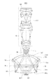
図1に示す通り、本発明の反射屈折光学系104は、物体103からの光束を集光して物体の中間像IMを形成する反射屈折部CATと、中間像IMが形成される位置に配置されたフィールドレンズ部FLとを有する。更に中間像IMを像面(撮像素子105)に結像させる屈折部DIOを有する。また、本発明の撮像装置1000は光源手段101と、光源手段101からの光束で物体103を照明する照明光学系102と、物体103を結像する反射屈折光学系104を有する。更に反射屈折光学系104によって結像された物体像を光電変換する撮像素子105と、撮像素子105からのデータより画像情報を生成する画像処理系106とを有する。
As shown in FIG. 1, the catadioptric
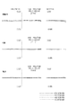
図1は本発明の撮像装置の要部概略図である。図2は本発明の反射屈折光学系の実施例1の要部概略図である。図3は本発明の反射屈折光学系の実施例1の横収差図である。図4は本発明の反射屈折光学系の実施例2の要部概略図である。図5は本発明の反射屈折光学系の実施例2の横収差図である。図6は本発明の反射屈折光学系の実施例3の要部概略図である。図7は本発明の反射屈折光学系の実施例3の横収差図である。図8は本発明の反射屈折光学系の実施例4の要部概略図である。図9は本発明の反射屈折光学系の実施例4の横収差図である。 FIG. 1 is a schematic diagram of a main part of an imaging apparatus according to the present invention. FIG. 2 is a schematic view of the essential portions of Embodiment 1 of the catadioptric optical system of the present invention. FIG. 3 is a transverse aberration diagram for Example 1 of the catadioptric optical system of the present invention. FIG. 4 is a schematic view of the essential portions of Embodiment 2 of the catadioptric optical system of the present invention. FIG. 5 is a transverse aberration diagram for Example 2 of the catadioptric optical system of the present invention. FIG. 6 is a schematic view of the essential portions of Embodiment 3 of the catadioptric optical system of the present invention. FIG. 7 is a transverse aberration diagram for Example 3 of the catadioptric optical system of the present invention. FIG. 8 is a schematic view of the essential portions of Embodiment 4 of the catadioptric optical system of the present invention. FIG. 9 is a transverse aberration diagram for Example 4 of the catadioptric optical system of the present invention.
横収差図は、試料103上で収差を計算した結果を、ミリメートル単位で、中心波長587.6nm、波長656.3nm、波長486.1nm、波長435.8nmに関して示した。
The lateral aberration diagram shows the result of calculating the aberration on the
以下、図1を参照して、本発明の反射屈折光学系104を有する撮像装置1000の構成について説明する。撮像装置1000は、光源(光源手段)101からの光を照明光学系102によって集光して試料(物体)103を均一に照明する。このとき使用する光は可視光(例えば、波長400nm〜波長700nm)が用いられる。結像光学系104は、試料(物体)103の像を撮像素子105上に結像する反射屈折光学系より成っている。撮像素子105で取得した信号(画像情報)から画像処理系106によって画像データを生成し、生成した画像データをディスプレイ(表示手段)107などに表示する。画像処理系106では結像光学系104で補正しきれなかった収差を補正する、または撮像位置の異なった画像データを繋げて一枚の画像データに合成するなど用途に応じた処理が行われる。
Hereinafter, with reference to FIG. 1, the structure of the
図2、4、6、8に示すように、各実施例の反射屈折光学系104は、試料(物体)103の光束を集光し、所定面に中間像IMを形成する反射面と屈折面を含む反射屈折部CATを有する。更に、中間像IMからの光束を集光し、後述する屈折部DIO方向へ導光するフィールドレンズ部FLを有し、中間像IMを撮像素子(像面)105に結像する屈折部DIOを有する。
As shown in FIGS. 2, 4, 6, and 8, the catadioptric
反射屈折光学系104を構成する反射屈折部CATは、物体側から順に、第1の光学素子M1と第2の光学素子M2を少なくとも有する。第1の光学素子M1は、試料103側(物体側)の面M1aが凸形状で光軸周辺が正の屈折力の光透過部M1Tと、その外周側に試料103側の面M1aに反射面(例えばアルミや銀等の反射膜)が施された裏面反射部を有する。第2の光学素子M2は、試料103側に凹面を向け、メニスカス形状で光軸周辺が負の屈折力の光透過部M2Tと、その外周側に撮像素子105側(像面側)の面M2bに反射面(例えばアルミや銀等の反射膜)が施された裏面反射部を有する。第1の光学素子M1の裏面反射部の反射面と第2の光学素子M2の裏面反射部の反射面が向き合うように配置されている。
The catadioptric unit CAT constituting the catadioptric
屈折部DIOは、試料103からの光束のうち面M1aや面M2bで反射されずに直接光透過部を通過してきた光軸近傍の光束を遮光し、撮像素子105に入射するのを防止する遮光板SHを有する。このとき遮光する領域を大きくすると結像性を悪化させてしまうため、なるべく遮光する割合(以後この割合を遮光率とする)を低くすることが重要である。
The refracting unit DIO shields the light beam near the optical axis that has directly passed through the light transmitting part without being reflected by the surface M1a and the surface M2b from the
各実施例の反射屈折光学系104では、照明光学系102からの光束で照明され、試料103から出射した光束は第1の光学素子M1の光透過部M1Tを通過する。その後、第2の光学素子M2の屈折面M2aに入射し、その後裏面M2bで反射し、反射面M2aを通過して第1の光学素子M1の屈折面M1bに入射する。その後、第1の光学素子M1の裏面M1aで反射する。そして屈折面M1bを通過し、第2の光学素子M2の光透過部M2Tを通過して通過してフィールドレンズ部FL側へ出射し、試料103の中間像IMを形成する。中間像IMは、フィールドレンズ部FLを構成するレンズ内部に形成される。中間像IMは、複数の屈折光学素子を含む屈折部DIOによって撮像素子105上に拡大結像される。撮像素子105に結像された試料103の像は画像処理系106によって処理されて、表示手段107に表示される。
In the catadioptric
各実施例において、第2の光学素子M2の物体側と像側の面M2a、M2bの曲率半径を各々RM2a、RM2bとする。第2の光学素子M2の光軸上の厚さをtとする。第2の光学素子M2の材料の波長587.6nmでの屈折率をNdとする。そして In each embodiment, the radii of curvature of the object-side and image-side surfaces M2a and M2b of the second optical element M2 are RM2a and RM2b, respectively. Let t be the thickness of the second optical element M2 on the optical axis. Let Nd be the refractive index of the material of the second optical element M2 at a wavelength of 587.6 nm. And
とおいたとき、
Rapl×0.8<|RM2a|<Rapl×1.2 ・・・(1)
なる条件を満足するのが良い。
When
Rapl × 0.8 <| RM2a | <Rapl × 1.2 (1)
It is good to satisfy the condition.
また第2の光学素子M2の硝材のアッベ数をνM2とする。このとき
νM2>40 ・・・(2)
なる条件を満足している。
Further, the Abbe number of the glass material of the second optical element M2 is νM2. At this time, νM2> 40 (2)
Is satisfied.
条件式(1)は、第2の光学素子M2の物体側の面M2aに強い負の屈折力を持たせても収差の発生を抑制し、広い波長領域に渡って収差を低減するためのものである。第2の光学素子M2の屈折面M2aの強い負の屈折力により強い発散作用を持たせることは、以下に示すような光学効果を得るためにも重要である。
・正レンズ作用の第1の光学素子M1の中心付近の光透過部を有効径と比較して相対的に小さくすることができ、遮光率を低く抑えることができる。
・反射屈折部CATと屈折部DIOの軸上色収差を相殺することができるため、屈折部DIOの凸レンズパワー(正レンズの屈折力)を強くすることができ、全長の短縮が容易になる。
Conditional expression (1) is for suppressing the occurrence of aberrations and reducing aberrations over a wide wavelength region even if the object-side surface M2a of the second optical element M2 has a strong negative refractive power. It is. Providing a strong diverging action by the strong negative refractive power of the refracting surface M2a of the second optical element M2 is important in order to obtain the following optical effect.
The light transmission part near the center of the first optical element M1 having a positive lens action can be made relatively smaller than the effective diameter, and the light shielding rate can be kept low.
Since the axial chromatic aberration of the catadioptric unit CAT and the refractive unit DIO can be canceled, the convex lens power (refractive power of the positive lens) of the refractive unit DIO can be increased, and the overall length can be easily shortened.
ここで(a1)式は、反射面M2bに対する結像関係の式であり、物点が屈折面M2aの曲率中心にあり、像点が反射面M2bから距離S’の位置にあることを表している。(a2)式は、反射面M2bから距離S’の位置にある虚像の物点に対し、屈折面M2aがアプラナティックな条件となるための曲率半径Raplを示している。 Here, the expression (a1) is an expression of the image formation relationship with respect to the reflecting surface M2b, and represents that the object point is at the center of curvature of the refracting surface M2a and the image point is at a distance S ′ from the reflecting surface M2b. Yes. Expression (a2) represents a radius of curvature Rapl for the refractive surface M2a to be an aplanatic condition with respect to the object point of the virtual image located at a distance S ′ from the reflecting surface M2b.
条件式(1)は、屈折面M2aがアプラナティックな条件となるための曲率半径Raplからどの程度外れて良いかを示している。条件式(1)である程度幅があるのは、他の面で発生する収差とのバランスを取るためであり、第1の光学素子M1とバランスを取るためにも条件式(1)を満たすことが好ましい。条件式(1)を満たさないと第2の光学素子M2の屈折面M2aで大きな収差が発生し、広い波長領域に渡って収差を抑制することが困難となる。 Conditional expression (1) indicates how far the refracting surface M2a can deviate from the radius of curvature Rapl for the aplanatic condition. Conditional expression (1) has a certain range in order to balance aberrations generated on other surfaces, and also satisfies conditional expression (1) in order to balance with first optical element M1. Is preferred. If the conditional expression (1) is not satisfied, a large aberration occurs on the refractive surface M2a of the second optical element M2, and it is difficult to suppress the aberration over a wide wavelength region.
条件式(2)は、第2の光学素子M2の硝材を低分散にすることで、2次の軸上色収差を低減するためのものである。通常の屈折光学系では、物体を結像させるために正レンズのパワーを負レンズのパワーより強くしなければならない。そのため、正レンズに低分散の硝材、負レンズに高分散の硝材を用いることによって色収差の補正を行っている。このとき、低分散の硝材と高分散の硝材で波長に対する屈折率変化の割合が違うため、2次の色収差となって現れる。一方、本実施例に係る反射屈折光学系では、第2の光学素子M2の負の屈折面M2aのパワー(屈折力)を大きくしても、色収差の生じない反射面M2bのパワーを強くすることで結像させることができる。このため、第2の光学素子M2の硝材に低分散の(アッベ数の大きな)硝材を用いることで、2次の軸上色収差を低減することができる。条件式(2)を満たさないと2次の軸上色収差を低減することができず、広い波長領域に渡って収差を抑制することが困難となる。 Conditional expression (2) is for reducing secondary axial chromatic aberration by reducing the dispersion of the glass material of the second optical element M2. In a normal refractive optical system, the power of the positive lens must be stronger than the power of the negative lens in order to form an object. Therefore, chromatic aberration is corrected by using a low dispersion glass material for the positive lens and a high dispersion glass material for the negative lens. At this time, since the rate of change in the refractive index with respect to the wavelength is different between the low-dispersion glass material and the high-dispersion glass material, secondary chromatic aberration appears. On the other hand, in the catadioptric optical system according to the present embodiment, even if the power (refractive power) of the negative refracting surface M2a of the second optical element M2 is increased, the power of the reflecting surface M2b that does not cause chromatic aberration is increased. Can be imaged. For this reason, the secondary axial chromatic aberration can be reduced by using a low dispersion (large Abbe number) glass material for the glass material of the second optical element M2. If the conditional expression (2) is not satisfied, the secondary axial chromatic aberration cannot be reduced, and it becomes difficult to suppress the aberration over a wide wavelength region.
各実施例では(a1)、(a2)、条件式(1)の3つの式を満たすことによって、以下に示すような屈折面M2aでの収差が抑えられた構成とすることができる。
・最初に屈折面M2aに入射する光線がほぼ0度で入射する。
・反射面M2bによって反射された光線が屈折面M2aから射出する際、屈折面M2aの曲率半径がアプラナティックな条件となっている。
In each embodiment, by satisfying the three expressions (a1), (a2), and conditional expression (1), it is possible to obtain a configuration in which the aberration on the refractive surface M2a as shown below is suppressed.
A light beam incident on the refractive surface M2a first enters at approximately 0 degrees.
When the light beam reflected by the reflecting surface M2b exits from the refracting surface M2a, the radius of curvature of the refracting surface M2a is an aplanatic condition.
各実施例において最も有効径の大きな屈折面M2aで収差を低減することにより、広い波長領域に渡って収差を低減するのを容易にしている。 In each embodiment, the aberration is reduced over the wide wavelength region by reducing the aberration with the refractive surface M2a having the largest effective diameter.
更に好ましくは条件式(1)、(2)の数値を次の如く設定するのが良い。
Rapl×0.9<|RM2a|<Rapl×1.1 ・・・(1a)
νM2>50 ・・・(2a)
また、第2の光学素子M2の反射面は非球面形状を有し、光透過部M2T側から外周側にかけて曲率が緩やかになっていくことが好ましい。このように設定することで、色収差の発生を低減し、球面収差を良好に補正している。
More preferably, the numerical values of conditional expressions (1) and (2) are set as follows.
Rapl × 0.9 <| RM2a | <Rapl × 1.1 (1a)
νM2> 50 (2a)
Further, it is preferable that the reflecting surface of the second optical element M2 has an aspherical shape, and the curvature becomes gentle from the light transmitting portion M2T side to the outer peripheral side. By setting in this way, the occurrence of chromatic aberration is reduced and spherical aberration is corrected well.
[実施例1]
図2は、本発明の実施例1における反射屈折光学系104Aの要部断面図である。実施例1の反射屈折光学系において、物体側の開口数NAは0.7であって、結像倍率は10倍、試料103の物体高はφ14mmであり、反射屈折部CATに開口絞りASが配置されている。反射屈折部CATに開口絞りASを配置することによって、屈折部に配置する場合と比べて絞り径が大きくなってしまう半面、瞳の歪みを低減することができる。
[Example 1]
FIG. 2 is a cross-sectional view of a main part of the catadioptric
光学系104Aは、物体側、像面側ともテレセントリックに構成されており、遮光率が面積比で2割以下と抑えられている。また白色光での波面収差の最悪値が50mλ(rms)以下に抑えられている。
The
[実施例2]
図4は、本発明の実施例2における反射屈折光学系104Bの要部断面図である。図4において図2と同じ部材には同符号を付している。実施例2の構成は実施例1と略同じである。
[Example 2]
FIG. 4 is a cross-sectional view of a main part of the catadioptric optical system 104B according to the second embodiment of the present invention. 4, the same members as those in FIG. 2 are denoted by the same reference numerals. The configuration of Example 2 is substantially the same as that of Example 1.
実施例2の光学系において、物体側の開口数NAは0.7であって、結像倍率は4倍、試料103の物体高はφ20mmであり、実施例1と違い屈折部DIOに開口絞りASが配置されている。物体側、像面側ともテレセントリックに構成されており、遮光率が面積比で2割以下と抑えられている。また白色光での波面収差最悪値が50mλrms以下に抑えられている。
In the optical system of the second embodiment, the numerical aperture NA on the object side is 0.7, the imaging magnification is 4 times, and the object height of the
[実施例3]
図6は、本発明の実施例3における反射屈折光学系104Cの要部断面図である。図6において、図2と同じ部材には同符号を付している。実施例3の構成は実施例1と略同じである。
[Example 3]
FIG. 6 is a cross-sectional view of a main part of the catadioptric
実施例3の光学系において、物体側の開口数NAは0.7であって、結像倍率は6倍、試料103の物体高はφ17.5mmであり、実施例1と違い屈折部DIOに開口絞りASが配置されている。物体側、像面側ともテレセントリックに構成されており、遮光率が面積比で2割以下と抑えられている。また白色光での波面収差最悪値が100mλ(rms)以下に抑えられている。
In the optical system of Example 3, the numerical aperture NA on the object side is 0.7, the imaging magnification is 6 times, and the object height of the
[実施例4]
図8は、本発明の実施例4における反射屈折光学系104Dの要部断面図である。図8において、図2と同じ部材には同符号を付している。実施例4は実施例1に比べて反射屈折部CATの構成が異なっている。実施例4は反射屈折部CATを構成する第1、第2の光学素子M1、M2との間に平行平板PLを設けている。
試料103からの光束は、平行平板PLを2回通過してフィールドレンズ部FL側へ出射する。
[Example 4]
FIG. 8 is a cross-sectional view of a main part of a catadioptric optical system 104D in Embodiment 4 of the present invention. In FIG. 8, the same members as those in FIG. The fourth embodiment is different from the first embodiment in the configuration of the catadioptric unit CAT. In Example 4, a parallel plate PL is provided between the first and second optical elements M1 and M2 constituting the catadioptric unit CAT.
The light beam from the
本実施例では、平行平板PLの中心に遮光板SHを配置することによって、光軸近傍の光束を屈折部DIOに到達する前に遮光している。このことによって、屈折部DIO内で発生する不要光を減らすことができる。 In the present embodiment, the light shielding plate SH is arranged at the center of the parallel plate PL to shield the light flux near the optical axis before reaching the refracting portion DIO. Thereby, unnecessary light generated in the refracting portion DIO can be reduced.
また、平行平板PLを傾ける機構を備えることによって、組み立て時に発生するレンズの偏心によるコマ収差を調整することができる。 Further, by providing a mechanism for inclining the parallel plate PL, it is possible to adjust coma aberration caused by lens decentering that occurs during assembly.
実施例4の光学系において、物体側の開口数NAは0.7であって、倍率は4倍、資料103の物体高はφ20mmであり、実施例1と違い屈折部DIOに開口絞りASが配置されている。物体側、像面側ともテレセントリックに構成されており、遮光率が面積比で2割以下と抑えられている。また白色光での波面収差最悪値が50mλ(rms)以下に抑えられている。
In the optical system of the fourth embodiment, the numerical aperture NA on the object side is 0.7, the magnification is four times, the object height of the
以上、本発明の好ましい実施例について説明したが、本発明はこれらの実施例に限定されないことはいうまでもなく、その要旨の範囲内で種々の変形及び変更が可能である。例えば、本発明はスキャンすることで大きな試料を撮像する撮像装置にも、スキャンせずに試料を撮像する撮像装置にも適用可能である。 The preferred embodiments of the present invention have been described above, but the present invention is not limited to these embodiments, and various modifications and changes can be made within the scope of the gist. For example, the present invention can be applied to an imaging apparatus that images a large sample by scanning or an imaging apparatus that images a sample without scanning.
以下、各実施例の数値実施例を示す。面番号は、物体面(試料面)から像面まで数えた光学面の順番である。rは第i番目の光学面の曲率半径である。dは第i番目と第i+1番目の間隔である(符号は物体側から像面側へ測ったときを(光が近行するときを)正、逆方向を負としている)。 Hereinafter, numerical examples of the respective examples will be shown. The surface number is the order of the optical surfaces counted from the object surface (sample surface) to the image surface. r is the radius of curvature of the i-th optical surface. d is the i-th and i + 1-th interval (the sign is positive when measured from the object side to the image plane side (when light approaches) and negative in the reverse direction).
Nd、νdは波長587.6nmに対する材料の屈折率とアッベ数をそれぞれ示している。 Nd and νd indicate the refractive index and Abbe number of the material for a wavelength of 587.6 nm, respectively.
非球面の形状は、以下の式に示す一般的な非球面の式で表される。以下の式において、Zは光軸方向の座標、cは曲率(曲率半径rの逆数)、hは光軸からの高さ、kは円錐係数、a、b、c、d、e、f、g、h、i・・・は各々、4次、6次、8次、10次、12次、14次、16次、18次、20次、・・・の非球面係数である。 The shape of the aspheric surface is represented by a general aspherical expression shown in the following expression. In the following equation, Z is the coordinate in the optical axis direction, c is the curvature (the reciprocal of the radius of curvature r), h is the height from the optical axis, k is the cone coefficient, a, b, c, d, e, f, g, h, i... are aspherical coefficients of 4th order, 6th order, 8th order, 10th order, 12th order, 14th order, 16th order, 18th order, 20th order,.
![]()
![]()
「E−X」は「10−X」を意味する。前述した各条件式と数値実施例との関係を表−1に示す。 “ EX ” means “10 −X ”. Table 1 shows the relationship between the above-described conditional expressions and numerical examples.
(数値実施例1)
Rapl=87.52
RM2a=-87.05
νM2=40.75
面番号 r d Nd νd
物体面 5.31
1 572.96 11.74 1.52 64.14
2 -3971.93 70.93
3 -87.05 7.37 1.58 40.75
4 -115.96 -7.37 1.58 40.75
5 -87.05 -60.93
6 絞り -10.00
7 -3971.93 -11.74 1.52 64.14
8 572.96 11.74 1.52 64.14
9 -3971.93 70.93
10 -87.05 7.37 1.58 40.75
11 -115.96 4.40
12 -280.62 7.55 1.73 45.75
13 -24.25 5.00 1.76 27.58
14 -63.13 0.50
15 44.30 8.03 1.62 60.32
16 -134.04 15.13
17 64.29 14.17 1.56 58.80
18 -57.90 20.93
19 -26.52 5.00 1.70 33.94
20 -60.24 3.37
21 2035.38 15.68 1.63 35.46
22 -70.44 0.89
23 117.93 21.53 1.68 39.58
24 -74.17 0.50
25 56.79 12.02 1.74 30.97
26 177.00 3.06
27 165.39 5.00 1.76 27.58
28 53.42 40.67
29 -38.60 5.00 1.76 27.58
30 -229.85 13.99
31 -35.70 5.00 1.76 27.58
32 -181.79 11.22
33 -143.30 22.66 1.52 53.64
34 -56.43 23.57
35 -219.04 17.88 1.75 34.24
36 -110.37 1.09
37 -4269.61 17.81 1.63 57.69
38 -282.70 3.00
像面
(Numerical example 1)
Rapl = 87.52
RM2a = -87.05
νM2 = 40.75
Surface number rd Nd νd
Object surface 5.31
1 572.96 11.74 1.52 64.14
2 -3971.93 70.93
3 -87.05 7.37 1.58 40.75
4 -115.96 -7.37 1.58 40.75
5 -87.05 -60.93
6 Aperture -10.00
7 -3971.93 -11.74 1.52 64.14
8 572.96 11.74 1.52 64.14
9 -3971.93 70.93
10 -87.05 7.37 1.58 40.75
11 -115.96 4.40
12 -280.62 7.55 1.73 45.75
13 -24.25 5.00 1.76 27.58
14 -63.13 0.50
15 44.30 8.03 1.62 60.32
16 -134.04 15.13
17 64.29 14.17 1.56 58.80
18 -57.90 20.93
19 -26.52 5.00 1.70 33.94
20 -60.24 3.37
21 2035.38 15.68 1.63 35.46
22 -70.44 0.89
23 117.93 21.53 1.68 39.58
24 -74.17 0.50
25 56.79 12.02 1.74 30.97
26 177.00 3.06
27 165.39 5.00 1.76 27.58
28 53.42 40.67
29 -38.60 5.00 1.76 27.58
30 -229.85 13.99
31 -35.70 5.00 1.76 27.58
32 -181.79 11.22
33 -143.30 22.66 1.52 53.64
34 -56.43 23.57
35 -219.04 17.88 1.75 34.24
36 -110.37 1.09
37 -4269.61 17.81 1.63 57.69
38 -282.70 3.00
Image plane
(数値実施例2)
Rapl=147.19
RM2a=-118.31
νM2=70.24
面番号 r d Nd νd
物体面 13.39
1 736.61 24.08 1.49 70.24
2 -9661.75 97.67
3 -118.31 9.38 1.49 70.24
4 -170.29 -9.38 1.49 70.24
5 -118.31 -97.67
6 -9661.75 -24.08 1.49 70.24
7 736.61 24.08 1.49 70.24
8 -9661.75 97.67
9 -118.31 9.38 1.49 70.24
10 -170.29 10.00
11 -458.41 5.89 1.64 58.37
12 -119.83 3.29
13 -54.79 5.00 1.65 33.79
14 -998.82 11.55 1.62 60.25
15 -54.52 0.73
16 79.77 7.04 1.62 60.29
17 483.74 34.05
18 59.02 11.53 1.76 40.10
19 109.31 0.50
20 65.70 20.52 1.49 70.35
21 -118.81 26.00
22 絞り 18.84
23 -49.26 33.31 1.81 25.43
24 -79.27 0.50
25 122.53 26.67 1.64 55.38
26 -86.46 0.50
27 57.90 15.51 1.49 70.35
28 78.67 17.39
29 -124.44 5.74 1.57 42.86
30 58.49 15.64
31 -147.56 8.96 1.76 47.82
32 -75.81 11.90
33 -59.72 8.10 1.60 38.03
34 272.55 9.12
35 -178.62 19.27 1.72 34.72
36 -68.40 0.50
37 1362.89 16.90 1.51 60.49
38 -142.77 10.50
像面
(Numerical example 2)
Rapl = 147.19
RM2a = -118.31
νM2 = 70.24
Surface number rd Nd νd
Object plane 13.39
1 736.61 24.08 1.49 70.24
2 -9661.75 97.67
3 -118.31 9.38 1.49 70.24
4 -170.29 -9.38 1.49 70.24
5 -118.31 -97.67
6 -9661.75 -24.08 1.49 70.24
7 736.61 24.08 1.49 70.24
8 -9661.75 97.67
9 -118.31 9.38 1.49 70.24
10 -170.29 10.00
11 -458.41 5.89 1.64 58.37
12 -119.83 3.29
13 -54.79 5.00 1.65 33.79
14 -998.82 11.55 1.62 60.25
15 -54.52 0.73
16 79.77 7.04 1.62 60.29
17 483.74 34.05
18 59.02 11.53 1.76 40.10
19 109.31 0.50
20 65.70 20.52 1.49 70.35
21 -118.81 26.00
22 Aperture 18.84
23 -49.26 33.31 1.81 25.43
24 -79.27 0.50
25 122.53 26.67 1.64 55.38
26 -86.46 0.50
27 57.90 15.51 1.49 70.35
28 78.67 17.39
29 -124.44 5.74 1.57 42.86
30 58.49 15.64
31 -147.56 8.96 1.76 47.82
32 -75.81 11.90
33 -59.72 8.10 1.60 38.03
34 272.55 9.12
35 -178.62 19.27 1.72 34.72
36 -68.40 0.50
37 1362.89 16.90 1.51 60.49
38 -142.77 10.50
Image plane
(数値実施例3)
Rapl=142.21
RM2a=-167.82
νM2=52.43
面番号 r d Nd νd
物体面 13.72
1 770.39 22.33 1.52 58.90
2 2378.98 111.82
3 -167.82 11.37 1.52 52.43
4 -207.81 -11.37 1.52 52.43
5 -167.82 -111.82
6 2378.98 -22.33 1.52 58.90
7 770.39 22.33 1.52 58.90
8 2378.98 111.82
9 -167.82 11.37 1.52 52.43
10 -207.81 5.32
11 -93.86 16.27 1.74 44.85
12 -69.67 8.31
13 -61.43 9.19 1.76 27.58
14 144.61 9.27 1.63 57.85
15 -53.51 0.50
16 47.71 14.72 1.62 60.32
17 140.40 11.60
18 57.13 21.31 1.70 48.31
19 -40.24 6.48 1.67 32.07
20 -89.71 16.86
21 絞り 13.99
22 -32.96 5.71 1.51 60.74
23 -270.01 8.97
24 -379.49 14.34 1.75 28.15
25 -67.23 1.24
26 211.55 19.56 1.58 57.81
27 -76.67 0.52
28 59.11 17.64 1.62 60.34
29 1974.65 6.99
30 -254.08 5.06 1.76 27.58
31 66.65 17.14
32 -70.16 8.91 1.74 37.46
33 -47.20 4.82
34 -41.79 5.00 1.51 63.55
35 327.69 20.12
36 -38.88 6.83 1.76 27.58
37 -156.16 4.60
38 -158.31 22.61 1.74 42.70
39 -61.08 0.76
40 353.15 19.11 1.69 49.27
41 -226.39 17.00
像面
(Numerical Example 3)
Rapl = 142.21
RM2a = -167.82
νM2 = 52.43
Surface number rd Nd νd
Object plane 13.72
1 770.39 22.33 1.52 58.90
2 2378.98 111.82
3 -167.82 11.37 1.52 52.43
4 -207.81 -11.37 1.52 52.43
5 -167.82 -111.82
6 2378.98 -22.33 1.52 58.90
7 770.39 22.33 1.52 58.90
8 2378.98 111.82
9 -167.82 11.37 1.52 52.43
10 -207.81 5.32
11 -93.86 16.27 1.74 44.85
12 -69.67 8.31
13 -61.43 9.19 1.76 27.58
14 144.61 9.27 1.63 57.85
15 -53.51 0.50
16 47.71 14.72 1.62 60.32
17 140.40 11.60
18 57.13 21.31 1.70 48.31
19 -40.24 6.48 1.67 32.07
20 -89.71 16.86
21 Aperture 13.99
22 -32.96 5.71 1.51 60.74
23 -270.01 8.97
24 -379.49 14.34 1.75 28.15
25 -67.23 1.24
26 211.55 19.56 1.58 57.81
27 -76.67 0.52
28 59.11 17.64 1.62 60.34
29 1974.65 6.99
30 -254.08 5.06 1.76 27.58
31 66.65 17.14
32 -70.16 8.91 1.74 37.46
33 -47.20 4.82
34 -41.79 5.00 1.51 63.55
35 327.69 20.12
36 -38.88 6.83 1.76 27.58
37 -156.16 4.60
38 -158.31 22.61 1.74 42.70
39 -61.08 0.76
40 353.15 19.11 1.69 49.27
41 -226.39 17.00
Image plane
(数値実施例4)
Rapl=145.96
RM2a=-122.05
νM2=52.43
面番号 r d Nd νd
物体面 13.39
1 819.00 16.40 1.49 70.24
2 -3201.41 28.35
3 ∞ 13.97 1.49 70.24
4 ∞ 68.55
5 -122.05 9.54 1.52 52.43
6 -172.82 -9.54 1.52 52.43
7 -122.05 -68.55
8 ∞ -13.97 1.49 70.24
9 ∞ -28.35
10 -3201.41 -16.40 1.49 70.24
11 819.00 16.40 1.49 70.24
12 -3201.41 28.35
13 ∞ 13.97 1.49 70.24
14 ∞ 68.55
15 -122.05 9.54 1.52 52.43
16 -172.82 10.00
17 126.58 6.22 1.74 44.85
18 -950.12 9.32
19 -64.86 5.00 1.68 31.36
20 537.54 8.74 1.62 60.32
21 -56.79 0.50
22 82.22 7.50 1.49 70.41
23 635.34 23.00
24 64.84 14.27 1.69 49.87
25 618.89 5.01 1.76 27.58
26 709.49 10.48
27 -96.82 8.38 1.75 34.46
28 -68.50 28.14
29 絞り 48.00
30 -577.36 14.75 1.74 44.85
31 -104.66 0.50
32 116.63 19.70 1.74 44.85
33 -222.26 0.50
34 65.69 7.94 1.76 27.58
35 70.78 13.16
36 -483.66 5.00 1.74 28.39
37 53.97 51.45
38 -43.90 5.00 1.62 36.83
39 -429.14 6.13
40 -138.53 17.04 1.74 44.50
41 -58.87 0.50
42 357.86 13.06 1.74 44.85
43 -313.15 10.50
像面
(Numerical example 4)
Rapl = 145.96
RM2a = -122.05
νM2 = 52.43
Surface number rd Nd νd
Object plane 13.39
1 819.00 16.40 1.49 70.24
2 -3201.41 28.35
3 ∞ 13.97 1.49 70.24
4 ∞ 68.55
5 -122.05 9.54 1.52 52.43
6 -172.82 -9.54 1.52 52.43
7 -122.05 -68.55
8 ∞ -13.97 1.49 70.24
9 ∞ -28.35
10 -3201.41 -16.40 1.49 70.24
11 819.00 16.40 1.49 70.24
12 -3201.41 28.35
13 ∞ 13.97 1.49 70.24
14 ∞ 68.55
15 -122.05 9.54 1.52 52.43
16 -172.82 10.00
17 126.58 6.22 1.74 44.85
18 -950.12 9.32
19 -64.86 5.00 1.68 31.36
20 537.54 8.74 1.62 60.32
21 -56.79 0.50
22 82.22 7.50 1.49 70.41
23 635.34 23.00
24 64.84 14.27 1.69 49.87
25 618.89 5.01 1.76 27.58
26 709.49 10.48
27 -96.82 8.38 1.75 34.46
28 -68.50 28.14
29 Aperture 48.00
30 -577.36 14.75 1.74 44.85
31 -104.66 0.50
32 116.63 19.70 1.74 44.85
33 -222.26 0.50
34 65.69 7.94 1.76 27.58
35 70.78 13.16
36 -483.66 5.00 1.74 28.39
37 53.97 51.45
38 -43.90 5.00 1.62 36.83
39 -429.14 6.13
40 -138.53 17.04 1.74 44.50
41 -58.87 0.50
42 357.86 13.06 1.74 44.85
43 -313.15 10.50
Image plane
101 光源
102 照明光学系
103 試料
104 反射屈折光学系
105 撮像素子
IM 中間像
CAT 反射屈折部
FL フィールドレンズ部
DIO 屈折部
M1 第1の光学素子
M2 第2の光学素子
DESCRIPTION OF
Claims (6)
該反射屈折部は、該物体側から順に、該物体側の面が凸形状で光軸周辺に設けられた正の屈折力の光透過部と該光透過部より外周側に設けられた該物体側の面が反射面である裏面反射部とを有する第1の光学素子と、該物体側に凹面を向けたメニスカス形状で光軸周辺に設けられた負の屈折力の光透過部と該光透過部より外周側に設けられた該像面側の面が反射面である裏面反射部とを有する第2の光学素子とを有し、該第1の光学素子の裏面反射部の反射面と該第2の光学素子の裏面反射部の反射面とが向き合うように配置されており、
該物体からの光束は、順に該第1の光学素子の光透過部、該第2の光学素子の裏面反射部、該第1の光学素子の裏面反射部、該第2の光学素子の光透過部を介して、該フィールドレンズ部側へ出射しており、
該第2の光学素子の該物体側と該像面側の面の曲率半径を各々RM2a、RM2b、該第2の光学素子の光軸上の厚さをt、該第2の光学素子の材料の波長587.6nmでの屈折率をNdとし、
とおいたとき、
Rapl×0.8<|RM2a|<Rapl×1.2
なる条件を満足することを特徴とする反射屈折光学系。 A catadioptric unit that collects a light beam from an object to form an intermediate image of the object, a field lens unit disposed at a position where the intermediate image is formed, and a refraction that forms the intermediate image on the image plane A catadioptric optical system having a portion,
The catadioptric unit, in order from the object side, has a convex surface on the object side and has a positive refracting light transmitting part provided around the optical axis and the object provided on the outer peripheral side from the light transmitting part. A first optical element having a back surface reflecting portion whose side surface is a reflecting surface, a light transmitting portion having a negative refractive power provided around the optical axis in a meniscus shape with a concave surface facing the object side, and the light A second optical element having a back surface reflecting portion whose surface on the image side provided on the outer peripheral side from the transmitting portion is a reflecting surface, and a reflecting surface of the back surface reflecting portion of the first optical element; The second optical element is disposed so that the reflection surface of the back surface reflection portion faces each other,
The light beam from the object is sequentially transmitted through the light transmission part of the first optical element, the back surface reflection part of the second optical element, the back surface reflection part of the first optical element, and the light transmission of the second optical element. Exits to the field lens part side through the part,
RM2a and RM2b are the curvature radii of the object-side surface and the image-side surface of the second optical element, respectively, the thickness on the optical axis of the second optical element is t, and the material of the second optical element The refractive index at a wavelength of 587.6 nm is Nd,
When
Rapl × 0.8 <| RM2a | <Rapl × 1.2
A catadioptric optical system characterized by satisfying the following conditions:
νM2>40
なる条件を満足することを特徴とする請求項1に記載の反射屈折光学系。 When the Abbe number of the glass material of the second optical element is νM2,
νM2> 40
The catadioptric optical system according to claim 1, wherein the following condition is satisfied.
Priority Applications (2)
| Application Number | Priority Date | Filing Date | Title |
|---|---|---|---|
| JP2011200546A JP2013061530A (en) | 2011-09-14 | 2011-09-14 | Catadioptric system and imaging apparatus having the same |
| US13/609,677 US20130063650A1 (en) | 2011-09-14 | 2012-09-11 | Catadioptric system and image pickup apparatus equipped with same |
Applications Claiming Priority (1)
| Application Number | Priority Date | Filing Date | Title |
|---|---|---|---|
| JP2011200546A JP2013061530A (en) | 2011-09-14 | 2011-09-14 | Catadioptric system and imaging apparatus having the same |
Publications (2)
| Publication Number | Publication Date |
|---|---|
| JP2013061530A true JP2013061530A (en) | 2013-04-04 |
| JP2013061530A5 JP2013061530A5 (en) | 2014-10-23 |
Family
ID=47829555
Family Applications (1)
| Application Number | Title | Priority Date | Filing Date |
|---|---|---|---|
| JP2011200546A Withdrawn JP2013061530A (en) | 2011-09-14 | 2011-09-14 | Catadioptric system and imaging apparatus having the same |
Country Status (2)
| Country | Link |
|---|---|
| US (1) | US20130063650A1 (en) |
| JP (1) | JP2013061530A (en) |
Cited By (2)
| Publication number | Priority date | Publication date | Assignee | Title |
|---|---|---|---|---|
| JP2015036706A (en) * | 2013-08-12 | 2015-02-23 | キヤノン株式会社 | Imaging device |
| CN111352224A (en) * | 2019-11-22 | 2020-06-30 | 莆田学院 | Catadioptric panoramic imaging system and imaging method thereof |
Families Citing this family (2)
| Publication number | Priority date | Publication date | Assignee | Title |
|---|---|---|---|---|
| KR20150141820A (en) * | 2014-06-10 | 2015-12-21 | 삼성전자주식회사 | Objective lens assembly having catadioptric group |
| CN110927940B (en) * | 2019-12-19 | 2022-02-08 | 浙江舜宇光学有限公司 | Image pickup apparatus |
Family Cites Families (4)
| Publication number | Priority date | Publication date | Assignee | Title |
|---|---|---|---|---|
| US6483638B1 (en) * | 1996-07-22 | 2002-11-19 | Kla-Tencor Corporation | Ultra-broadband UV microscope imaging system with wide range zoom capability |
| US6631036B2 (en) * | 1996-09-26 | 2003-10-07 | Carl-Zeiss-Stiftung | Catadioptric objective |
| US6842298B1 (en) * | 2000-09-12 | 2005-01-11 | Kla-Tencor Technologies Corporation | Broad band DUV, VUV long-working distance catadioptric imaging system |
| US7884998B2 (en) * | 2003-02-21 | 2011-02-08 | Kla - Tencor Corporation | Catadioptric microscope objective employing immersion liquid for use in broad band microscopy |
-
2011
- 2011-09-14 JP JP2011200546A patent/JP2013061530A/en not_active Withdrawn
-
2012
- 2012-09-11 US US13/609,677 patent/US20130063650A1/en not_active Abandoned
Cited By (2)
| Publication number | Priority date | Publication date | Assignee | Title |
|---|---|---|---|---|
| JP2015036706A (en) * | 2013-08-12 | 2015-02-23 | キヤノン株式会社 | Imaging device |
| CN111352224A (en) * | 2019-11-22 | 2020-06-30 | 莆田学院 | Catadioptric panoramic imaging system and imaging method thereof |
Also Published As
| Publication number | Publication date |
|---|---|
| US20130063650A1 (en) | 2013-03-14 |
Similar Documents
| Publication | Publication Date | Title |
|---|---|---|
| EP3306369A1 (en) | Endoscope objective optical system | |
| TW201232082A (en) | Optical lens assembly | |
| JP5479206B2 (en) | Catadioptric optical system and imaging apparatus having the same | |
| EP3514596A1 (en) | Optical system, and head-mounted display apparatus employing same | |
| JP6416070B2 (en) | Imaging lens and imaging device provided with imaging lens | |
| US20090310230A1 (en) | Transmitting optical element and optical system using the same | |
| JP5836686B2 (en) | Catadioptric optical system and imaging apparatus having the same | |
| JP2013061530A (en) | Catadioptric system and imaging apparatus having the same | |
| JP5479224B2 (en) | Catadioptric optical system and imaging apparatus having the same | |
| JP5868063B2 (en) | Imaging device | |
| JPH07318797A (en) | Lens for infrared ray | |
| JP5506535B2 (en) | Imaging lens and inspection apparatus equipped with the imaging lens | |
| JP5656682B2 (en) | Catadioptric optical system and imaging apparatus having the same | |
| US20150043063A1 (en) | Catadioptric system and image pickup apparatus including the system | |
| JP2013015718A (en) | Catadioptric system and imaging device having the same | |
| JP2015176134A (en) | imaging device | |
| RU2386156C1 (en) | Optical system with remote apertures for infrared spectrum | |
| JP2015036706A5 (en) | ||
| JPH10260350A (en) | Infrared-ray image pickup device | |
| JP3655689B2 (en) | Endoscopic eyepiece system | |
| JP2015184544A (en) | Catadioptric optical system and imaging device having the same | |
| JP5627476B2 (en) | Catadioptric optical system and imaging apparatus having the same | |
| JP2014081511A (en) | Reflective/refractive optical system and imaging apparatus having the same | |
| JP2017003639A (en) | Radiographic image detection lens device | |
| JP2016212149A (en) | Imaging optical system and reading device having the same |
Legal Events
| Date | Code | Title | Description |
|---|---|---|---|
| A521 | Request for written amendment filed |
Free format text: JAPANESE INTERMEDIATE CODE: A523 Effective date: 20140909 |
|
| A621 | Written request for application examination |
Free format text: JAPANESE INTERMEDIATE CODE: A621 Effective date: 20140909 |
|
| A761 | Written withdrawal of application |
Free format text: JAPANESE INTERMEDIATE CODE: A761 Effective date: 20150501 |
|
| A977 | Report on retrieval |
Free format text: JAPANESE INTERMEDIATE CODE: A971007 Effective date: 20150513 |