JP2013060330A - Method of producing calcium fluoride - Google Patents
Method of producing calcium fluoride Download PDFInfo
- Publication number
- JP2013060330A JP2013060330A JP2011200109A JP2011200109A JP2013060330A JP 2013060330 A JP2013060330 A JP 2013060330A JP 2011200109 A JP2011200109 A JP 2011200109A JP 2011200109 A JP2011200109 A JP 2011200109A JP 2013060330 A JP2013060330 A JP 2013060330A
- Authority
- JP
- Japan
- Prior art keywords
- calcium fluoride
- hydrofluoric acid
- calcium
- calcium carbonate
- reaction
- Prior art date
- Legal status (The legal status is an assumption and is not a legal conclusion. Google has not performed a legal analysis and makes no representation as to the accuracy of the status listed.)
- Granted
Links
Images


Landscapes
- Compounds Of Alkaline-Earth Elements, Aluminum Or Rare-Earth Metals (AREA)
- Removal Of Specific Substances (AREA)
Abstract
Description
本発明は、フッ酸を含有する原水と炭酸カルシウムを反応させることにより、フッ化水素酸製造用の原料として好適なフッ化カルシウムを製造する方法に関する。 The present invention relates to a method for producing calcium fluoride suitable as a raw material for producing hydrofluoric acid by reacting raw water containing hydrofluoric acid with calcium carbonate.
従来、半導体産業や化学産業等において排出されるフッ素やリン酸を含有する原水に、水酸化カルシウム、酸化カルシウム、炭酸カルシウム、塩化カルシウムなどのカルシウム化合物を添加し、フッ化カルシウムやリン酸カルシウムなどの難溶性塩を晶析させ、回収して再利用する技術が知られている。 Conventionally, calcium compounds such as calcium hydroxide, calcium oxide, calcium carbonate, and calcium chloride are added to raw water containing fluorine and phosphoric acid discharged in the semiconductor industry, chemical industry, etc., and difficulties such as calcium fluoride and calcium phosphate occur. A technique for crystallizing, recovering, and reusing a soluble salt is known.
この種の晶析技術を利用して、フッ化カルシウムを回収し、下記の反応式(1)に示すように、フッ化カルシウムと硫酸を反応させて、フッ化水素酸の製造が一般的に行われている。
また、ロータリーキルンでフッ化水素酸を製造する際、原料として使用するフッ化カルシウムは、キルン内で流動可能な大きさにする必要がある。原料のフッ化カルシウムとしては、一般的に天然に存在するアシッドグレードの蛍石が用いられ、この天然の蛍石を、キルン内で流動可能なように、例えば、15〜300μm程度の粒径まで粉砕し、使用される。 Moreover, when manufacturing hydrofluoric acid with a rotary kiln, it is necessary to make the calcium fluoride used as a raw material into the magnitude | size which can flow in a kiln. As the raw material calcium fluoride, naturally occurring acid grade fluorite is used, so that the natural fluorite can flow in the kiln, for example, to a particle size of about 15 to 300 μm. Crushed and used.
このような背景のもと、晶析技術を利用して、フッ化カルシウムを回収し、この回収したフッ化カルシウムを用いて、フッ化水素酸の製造を行うには、フッ化カルシウムの粒子径を適度に揃えること、および、不純物を含まない高い純度をもつフッ化カルシウムを用いることが重要な要素となる。 Against this background, calcium fluoride is recovered using crystallization technology, and hydrofluoric acid is produced using the recovered calcium fluoride. It is an important factor to arrange them appropriately and to use calcium fluoride having a high purity not containing impurities.
フッ化カルシウムを回収し再利用する技術として、例えば、特許文献1には、下記の反応式4のように、適度に粒径を揃えた炭酸カルシウムとフッ化水素を反応させて、炭酸カルシウムの骨格をほぼ保ったままフッ化カルシウムを製造する技術が開示されている。
特許文献1に記載の技術は、適度に粒径を揃え、大部分の炭酸カルシウムの粒径を保持したままフッ化カルシウムとして回収することができるが、例えば、フッ化水素酸製造に使用するロータリーキルンに投入可能な粒径(15〜300μm程度)の場合、炭酸カルシウムの中心部が未反応で残り、純度が70%程度となり不十分である問題点があった。 The technique described in Patent Document 1 can be recovered as calcium fluoride while keeping the particle size of most calcium carbonates moderately, and for example, a rotary kiln used for hydrofluoric acid production. In the case of a particle size (about 15 to 300 μm) that can be charged into the material, there is a problem that the central portion of calcium carbonate remains unreacted and the purity becomes insufficient at about 70%.
また、特許文献2に記載のような晶析技術を用いる場合、反応原料を溶解しておく必要があるため、フッ化カルシウムの原料は、塩化カルシウムが用いられる。フッ化カルシウムの合成原料として、塩化カルシウムを使用した場合、回収したフッ化カルシウム中に微量の塩素成分が混入することを避けることが難しい。 Moreover, when using the crystallization technique as described in Patent Document 2, it is necessary to dissolve the reaction raw material, and therefore calcium chloride is used as the raw material for calcium fluoride. When calcium chloride is used as a synthetic raw material for calcium fluoride, it is difficult to avoid a trace amount of chlorine components from being mixed into the recovered calcium fluoride.
そのため、特許文献2の晶析技術にてフッ化カルシウムを得て、この微量の塩素成分が混入したフッ化カルシウムを使用してフッ化水素酸を製造した場合、製造したフッ化水素酸中に塩酸成分が混入してしまい品質の悪化が懸念されるため、できるだけ塩素成分を含有したカルシウム化合物の使用は避けることが望ましい。 Therefore, when calcium fluoride is obtained by the crystallization technique of Patent Document 2 and hydrofluoric acid is produced using calcium fluoride mixed with a small amount of chlorine component, It is desirable to avoid the use of a calcium compound containing a chlorine component as much as possible since the hydrochloric acid component is mixed in and there is a concern about deterioration of quality.
このように、従来の晶析技術によりフッ化カルシウムを回収し再利用する種々の技術について開示されているが、回収したフッ化カルシウムの粒径や純度などの問題点があり、回収物の再利用技術が未だ確立されていないのが現状である。 As described above, various techniques for recovering and reusing calcium fluoride by a conventional crystallization technique have been disclosed, but there are problems such as the particle size and purity of the recovered calcium fluoride, so The present situation is that the utilization technology has not been established yet.
本発明は、上記の問題点に鑑みてなされたものであり、フッ化水素酸の製造時に塩酸成分混入の懸念がなく、フッ化水素酸製造用の原料として好適なフッ化カルシウムの製造方法を提供することを目的とする。 The present invention has been made in view of the above-described problems, and there is no concern of mixing hydrochloric acid components during the production of hydrofluoric acid, and a method for producing calcium fluoride suitable as a raw material for hydrofluoric acid production is provided. The purpose is to provide.
本発明者らは、上記問題点を解決するために、鋭意検討した結果、実質的に塩素成分を含有しない炭酸カルシウムに着目し、フッ酸含有水と炭酸カルシウムを反応させる際、フッ酸と炭酸カルシウムのモル比(反応当量)において、フッ酸が過剰な状態で反応させ、さらに、炭酸カルシウムの中心部まで完全に反応が進行するように十分な熟成時間を確保することによって、フッ化水素酸製造用の原料として好適なフッ化カルシウムを得ることができること、を見出し、本発明に至った。 As a result of intensive studies to solve the above problems, the present inventors have focused on calcium carbonate that does not substantially contain a chlorine component, and when reacting hydrofluoric acid-containing water and calcium carbonate, hydrofluoric acid and carbonic acid are reacted. Hydrofluoric acid is obtained by reacting in an excess amount of hydrofluoric acid at a molar ratio of calcium (reaction equivalent), and ensuring sufficient aging time so that the reaction proceeds completely to the center of calcium carbonate. The inventors have found that calcium fluoride suitable as a raw material for production can be obtained, and have reached the present invention.
すなわち、本発明は、フッ酸含有水と炭酸カルシウムの反応によるフッ化カルシウムの製造方法であって、フッ素濃度が50000mg/L以上であるフッ酸含有水において、炭酸カルシウムの反応を進行させる熟成時間を有する合成反応工程[1]、を含むことを特徴とするフッ化カルシウムの製造方法である。 That is, the present invention relates to a method for producing calcium fluoride by a reaction between hydrofluoric acid-containing water and calcium carbonate, and the aging time for allowing the calcium carbonate reaction to proceed in hydrofluoric acid-containing water having a fluorine concentration of 50000 mg / L or more. A method for producing calcium fluoride, comprising a synthesis reaction step [1] having
また、本発明において、さらに、前記工程[1]にて得られた、フッ化カルシウムを含むスラリー液のpHを調整する中和工程[2]と、前記中和工程[2]にて得られた中和後のスラリー液を脱水する脱水工程[3]と、前記脱水工程[3]にて脱水したフッ化カルシウムを洗浄する洗浄工程[4]と、含むようにしてもよい。 Further, in the present invention, the neutralization step [2] for adjusting the pH of the slurry liquid containing calcium fluoride obtained in the step [1] and the neutralization step [2] are further obtained. Further, a dehydration step [3] for dehydrating the neutralized slurry liquid and a washing step [4] for washing the calcium fluoride dehydrated in the dehydration step [3] may be included.
この構成によれば、工程[1]にて合成したフッ化カルシウムを、効率よく中和、洗浄することができ、より不純物の低減させることができる。 According to this configuration, the calcium fluoride synthesized in step [1] can be efficiently neutralized and washed, and impurities can be further reduced.
また、本発明において、前記工程[1]において、前記フッ酸含有水に、粒状の炭酸カルシウムを直接投入することが好ましい。 In the present invention, in the step [1], it is preferable to directly add granular calcium carbonate to the hydrofluoric acid-containing water.
この構成によれば、合成反応工程[1]におけるスラリー液のフッ酸濃度を高い状態に保つことができるため、炭酸カルシウムからフッ化カルシウムへの転化を効率的に行うことができる。さらに、粒状の炭酸カルシウムを直接フッ酸含有水に直接投入すればよいため、炭酸カルシウムのスラリー液を調整して、フッ酸含有水にスラリー液を投入するためのスラリー調整槽を設ける必要がなく、工程および製造装置の簡素化ができる。 According to this configuration, since the hydrofluoric acid concentration of the slurry liquid in the synthesis reaction step [1] can be kept high, conversion from calcium carbonate to calcium fluoride can be performed efficiently. Furthermore, since it is only necessary to directly add granular calcium carbonate to hydrofluoric acid-containing water, there is no need to prepare a slurry adjusting tank for adjusting the calcium carbonate slurry liquid and introducing the slurry liquid into the hydrofluoric acid-containing water. The process and the manufacturing apparatus can be simplified.
また、本発明において、前記工程[1]にて使用する炭酸カルシウムの量が、前記フッ酸含有水のフッ素濃度の0.7当量以上、0.98当量以下、とすることが好ましい。 Moreover, in this invention, it is preferable that the quantity of the calcium carbonate used at the said process [1] shall be 0.7 equivalent or more and 0.98 equivalent or less of the fluorine concentration of the said hydrofluoric acid containing water.
この構成によれば、フッ酸含有水中において、炭酸カルシウムの濃度に対して、フッ酸が十分に過剰に残留した状態で熟成させることができ、さらに、効率よく、炭酸カルシウムの中心部まで反応を進行させることが可能となる。 According to this configuration, the hydrofluoric acid-containing water can be aged in a state where hydrofluoric acid remains sufficiently excessive with respect to the concentration of calcium carbonate, and the reaction can be efficiently performed to the center of calcium carbonate. It is possible to proceed.
また、本発明において、前記工程[1]にて使用する炭酸カルシウムの平均粒径が、15μm以上、300μm以下、とすることが好ましい。さらには、30μm以上、150μm以下とすることが特に好ましい。なお、本明細書において、「平均粒径」とは、レーザー回折・散乱法によって求めた粒度分布における積算値50%(メジアン径)での粒子径を意味する。 Moreover, in this invention, it is preferable that the average particle diameter of the calcium carbonate used at the said process [1] shall be 15 micrometers or more and 300 micrometers or less. Furthermore, it is particularly preferably 30 μm or more and 150 μm or less. In the present specification, the “average particle diameter” means a particle diameter at an integrated value of 50% (median diameter) in a particle size distribution obtained by a laser diffraction / scattering method.
この構成によれば、一般的にフッ化水素製造に使用されるロータリーキルンに投入可能かつ好適な粒径のフッ化カルシウムを得ることが可能となり、ロータリーキルンに投入する前工程において、フッ化カルシウムを粉砕するなどの別途工程を設ける必要がなく、工程および製造装置を簡素化することが可能となる。 According to this configuration, it is possible to obtain calcium fluoride having a suitable particle diameter that can be charged into a rotary kiln that is generally used for hydrogen fluoride production, and the calcium fluoride is pulverized in the previous step of charging into the rotary kiln. It is not necessary to provide a separate process such as, and the process and the manufacturing apparatus can be simplified.
本発明によれば、フッ酸含有水と実質的に塩素成分を含有しない炭酸カルシウムを反応させる際に、反応場のフッ酸が過剰な状態で十分な熟成時間を確保し、炭酸カルシウムの中心部まで完全に反応を進行させることができる。そのため、フッ化水素酸の製造時に塩酸成分混入の懸念がなく、フッ化水素酸製造用の原料として好適なフッ化カルシウムを提供することが可能となる。 According to the present invention, when reacting hydrofluoric acid-containing water and calcium carbonate containing substantially no chlorine component, a sufficient aging time is ensured in a state where the hydrofluoric acid in the reaction field is excessive, and the central portion of the calcium carbonate. Until the reaction can proceed completely. Therefore, there is no concern of mixing hydrochloric acid components during the production of hydrofluoric acid, and calcium fluoride suitable as a raw material for producing hydrofluoric acid can be provided.
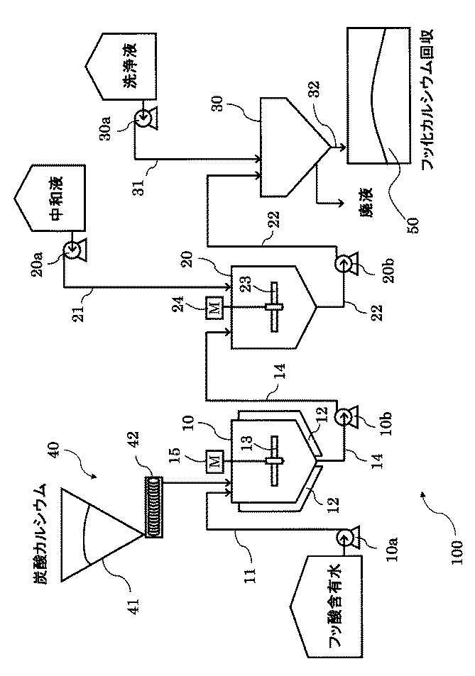
以下、図面を参照して、本発明の実施形態について説明する。まず、図1を参照して、本発明の実施の形態に適用可能なフッ化カルシウムの製造回収装置100の一例について説明する。
Embodiments of the present invention will be described below with reference to the drawings. First, an example of a calcium fluoride production and
本発明のフッ化カルシウムの製造回収装置100は、フッ酸含有水と炭酸カルシウムとを反応させフッ化カルシウムを合成するフッ化カルシウム合成槽10と、フッ化カルシウム合成槽10で合成したフッ化カルシウムの中心部まで、反応を十分に進行させる熟成槽20と、合成したフッ化カルシウムを含むスラリー液を固液分離操作によって脱水する脱水装置30と、を備える。
The calcium fluoride production and
フッ化カルシウム合成槽10には、供給ポンプ10aを介して、フッ酸含有水をフッ化カルシウム合成槽10に導入するフッ酸含有水供給配管11と、炭酸カルシウムをフッ化カルシウム合成槽10に導入する炭酸カルシウム導入手段40と、合成フッ化カルシウムを含むスラリー液を排出する第1スラリー液排出配管14が排出ポンプ10bを介して接続されている。なお、フッ化カルシウム合成槽10内には、モーター15を介して攪拌機13が設置される。
The hydrofluoric acid-containing
第1スラリー液排出配管14の下流には、排出ポンプ10bを介して熟成槽20が接続されており、熟成槽20には、貯留されたスラリー液の中和を行う中和液を供給するための中和液供給配管21が供給ポンプ20aを介して接続されている。また、熟成槽20には、スラリー液を排出して脱水装置30に送液するための第2スラリー液排出管22が設けられている。なお、熟成槽20内には、モーター24を介して攪拌機23が設置されている。
An
第2スラリー液排出管22の下流には、排出ポンプ20bを介して脱水装置30が接続されており、脱水装置30には、第2スラリー液排出管22を介して送液されたスラリー液を洗浄するための洗浄液を供給する洗浄液供給配管31が供給ポンプ30aを介して接続される。なお、洗浄液としては、水やエタノールなどの有機溶媒を使用することができ、例えば、残留塩素成分の観点から、塩素成分が10mg/L以下の純水を用いるとよい。また、脱水装置30には、フッ化カルシウムの回収配管32が設けられ、この配管32によって、脱水、洗浄後の合成フッ化カルシウム5が回収される。脱水装置30としては、通常、遠心分離機をすればよいが、その他の方式として、例えば、フィルタプレス脱水装置、ろ過式脱水装置(不織布フィルター型)を使用してもよい。
A
フッ化カルシウム合成槽10の外周には、冷却ジャケット12が周設されており、合成槽10内のスラリー液(フッ酸含有水と炭酸カルシウムの混合液)の温度が調整される。冷却ジャケット12の方式は特に限定されないが、例えば、フッ酸と炭酸カルシウムの反応においては、発熱を抑えるために好適なものとして、簡便な方式である冷水循環方式を用いて温度を調整するとよい。
A cooling
フッ化カルシウム合成槽10と熟成槽20において、槽の材質としては特に限定されないが、例えば、PFA、PTFEなどのフッ素樹脂やゴム製のライニング槽を使用することができる。
In the calcium
炭酸カルシウム導入手段40は、粒状の炭酸カルシウムの受入ポッパー41と、炭酸カルシウムを供給するためのスクリューフィーダ42と、を備えており、スクリューフィーダ42によって炭酸カルシウムの供給量(供給速度)が調整される。なお、炭酸カルシウムの供給速度は、反応による急速な発熱が起こらないように適宜調整される。
The calcium
次に、本発明の実施形態に係るフッ化カルシウムの製造回収工程について説明する。 Next, a process for producing and recovering calcium fluoride according to the embodiment of the present invention will be described.
本発明は、フッ酸含有水と炭酸カルシウムの反応によるフッ化カルシウムの製造方法であって、高濃度のフッ酸含有水、すなわち、フッ素濃度が50000mg/L以上であるフッ酸含有水において、炭酸カルシウムの反応を進行させる熟成時間を有する合成反応工程[1]、を含むことを特徴としている。 The present invention relates to a method for producing calcium fluoride by the reaction of hydrofluoric acid-containing water and calcium carbonate, in a high concentration hydrofluoric acid-containing water, that is, in a hydrofluoric acid-containing water having a fluorine concentration of 50000 mg / L or more. It includes a synthetic reaction step [1] having a ripening time for allowing the calcium reaction to proceed.
さらに、本発明において、上記の工程[1]に加えて、工程[1]にて得られた合成フッ化カルシウムを含むスラリー液のpHを調整する中和工程[2]と、工程[2]にて得られた中和後のスラリー液を脱水する脱水工程[3]と、工程[3]にて脱水した合成フッ化カルシウムを洗浄する洗浄工程[4]を、含むようにするとよい。 Furthermore, in this invention, in addition to said process [1], neutralization process [2] which adjusts the pH of the slurry liquid containing the synthetic calcium fluoride obtained by process [1], and process [2] It is preferable to include the dehydration step [3] for dehydrating the slurry liquid after neutralization obtained in step 1 and the washing step [4] for washing the synthetic calcium fluoride dehydrated in step [3].
以下、図1を参照して、それぞれの各工程について詳細説明する。 Hereinafter, each step will be described in detail with reference to FIG.
まず、本発明の合成反応工程[1]について説明する。工程[1]は、炭酸カルシウムをフッ酸含有水のフッ酸(HF)と反応させ、フッ化カルシウムを合成する工程である。まず、フッ酸廃液などのフッ酸含有水を貯留したタンクから、フッ酸含有水がフッ酸含有水供給配管11を介してフッ化カルシウム合成槽10に供給される。次いで、受入ホッパー41に収容された粒状の炭酸カルシウムが、スクリューフィーダ42を介して供給量を調整しながらフッ化カルシウム合成槽10に投入される。また、工程[1]は、炭酸カルシウムからフッ化カルシウムの転化反応を完全に進行させるために、十分な熟成時間を確保しやすいバッチプロセスが好適に用いられる。
First, the synthesis reaction step [1] of the present invention will be described. Step [1] is a step of reacting calcium carbonate with hydrofluoric acid (HF) containing hydrofluoric acid to synthesize calcium fluoride. First, hydrofluoric acid-containing water is supplied to a calcium
なお、炭酸カルシウム導入手段40としては、粒状の炭酸カルシウムを直接投入する方式以外に、別途調整槽を設け、炭酸カルシウムのスラリー溶液を調整し、フッ化カルシウム合成槽10に炭酸カルシウムスラリー溶液を投入する方式も採用可能であるが、本発明においては、粒状の炭酸カルシウムを直接投入方式がより好ましい。
As the calcium carbonate introduction means 40, in addition to the method of directly charging granular calcium carbonate, a separate adjustment tank is provided to adjust the calcium carbonate slurry solution, and the calcium carbonate slurry solution is charged to the calcium
その理由としては、炭酸カルシウムのスラリー溶液を投入する場合、別途、スラリー溶液を調整する調整槽を設けたり、フッ化カルシウム合成槽10の容積を大きくする必要があり装置が煩雑になる。加えて、スラリー液を供給する配管の液詰まりが懸念されるため10wt%程度のスラリー液にする必要がある。また、10wt%程度の濃度の薄いスラリー液を用いた場合、フッ化カルシウム合成槽10のフッ酸含有水のフッ素濃度が低くなってしまう、その結果、反応溶液のフッ素濃度を十分に高くすることができなくなり、本発明の特徴である、反応場のフッ素の高濃度によって炭酸カルシウムの中心部まで十分にフッ化カルシウム化する効果が得られにくくなるため、本発明においては、粒状の炭酸カルシウムを直接投入することが特に好ましい。
The reason for this is that when a slurry solution of calcium carbonate is added, an adjustment tank for adjusting the slurry solution needs to be provided separately, or the volume of the calcium
フッ化カルシウム合成槽10に導入されたフッ酸含有水と炭酸カルシウムの混合物であるスラリー液は、上述の反応式(4)に示すように、二酸化炭素(CO2)ガスの発泡を伴う発熱反応であるため、フッ化カルシウム合成槽10の外周に周設された冷却ジャケット12によって、スラリー液の温度が一定に保たれる。温度設定条件としては、使用する炭酸カルシウムの投入量、粒子径、フッ化カルシウム合成槽1の反応容器の容積量などによって適宜設定されるべきである。例えば、15μm以上、300μm以下の粒子径の炭酸カルシウムを使用する場合、設定温度は、5℃〜95℃、特には20〜50℃の範囲にて調整するとよい。
The slurry liquid, which is a mixture of hydrofluoric acid-containing water and calcium carbonate introduced into the calcium
炭酸カルシウムの粒子径は、15μm以上、300μm以下、とすることが好ましい。さらには、30μm以上、150μm以下とすることが特に好ましい。その理由としては、300μmより大きくなると、炭酸カルシウムからフッ化カルシウムへの転化率が減少し、本発明における熟成時間が長くなってしまい効率的でない。また、合成後のフッ化カルシウムの粒径が、15μmより小さくなると、ローターリーキルンを使用してフッ化水素製造の原料として投入した場合、流動性に問題点が生じやすいため好ましくない。ロータリーキルンによるフッ化水素製造用原料として使用するには、30μm以上、150μm以下の炭酸カルシウムの粒径が特に好適である。この範囲にすることによって、好適な大きさのフッ化カルシウムを合成することができる。 The particle size of calcium carbonate is preferably 15 μm or more and 300 μm or less. Furthermore, it is particularly preferably 30 μm or more and 150 μm or less. The reason is that if it exceeds 300 μm, the conversion rate from calcium carbonate to calcium fluoride decreases, and the aging time in the present invention becomes longer, which is not efficient. Further, if the particle size of the synthesized calcium fluoride is smaller than 15 μm, it is not preferable because a problem is caused in the fluidity when a rotary kiln is used as a raw material for producing hydrogen fluoride. For use as a raw material for producing hydrogen fluoride by a rotary kiln, a particle size of calcium carbonate of 30 μm or more and 150 μm or less is particularly suitable. By setting this range, it is possible to synthesize calcium fluoride having a suitable size.
フッ化カルシウム合成槽10において、上述の反応式(4)に示されるように、フッ酸含有水に含まれるフッ酸と粒状の炭酸カルシウムが反応して、フッ化カルシウムの結晶が合成される。粒状の炭酸カルシウムの中心部まで完全に反応させるために、反応場に酸が過剰な状態で反応させることが好ましい。具体的には、フッ酸含有水中のフッ素濃度を、50000mg/L以上、530000mg/L以下、とし、さらには、100000mg/L以上、530000mg/L以下とすることが特に好ましい。
In the calcium
フッ素濃度が、530000mg/Lより大きい場合、フッ酸含有水中のフッ酸蒸気圧が高くなるため、炭酸カルシウムと反応させる際に生じる二酸化炭素(CO2)のガス発生に同伴して、フッ化水素蒸気が発生するため、撹拌機や炭酸カルシウム粉体投入機などの装置の腐食に繋がってしまうため、好ましくない。また、フッ素濃度が、50000mg/Lより小さい場合、反応場の酸の濃度が十分でなく、炭酸カルシウムのフッ化カルシウム化の反応を効率的に行うことができなくなるため、好ましくない。 When the fluorine concentration is greater than 530000 mg / L, the hydrofluoric acid vapor pressure in the hydrofluoric acid-containing water increases, so that the hydrogen fluoride is accompanied by the generation of carbon dioxide (CO 2 ) gas generated when reacting with calcium carbonate. Since steam is generated, it leads to corrosion of devices such as a stirrer and a calcium carbonate powder charging machine, which is not preferable. Moreover, when the fluorine concentration is smaller than 50000 mg / L, the concentration of the acid in the reaction field is not sufficient, and the reaction of calcium carbonate to calcium fluoride cannot be efficiently performed, which is not preferable.
上記反応式(4)をもとに、粒状の炭酸カルシウムの中心部まで完全に反応させるために、反応場に酸が過剰な状態で反応させる。酸の濃度を過剰にするために、フッ酸が、反応式(4)における化学当量より多くなるように反応液を調整する。具体的には、投入する炭酸カルシウムの量が、フッ酸との反応に必要な量の0.7当量以上、0.98当量以下、に調整することが好ましい。0.7当量より小さい場合は、中和工程[2]におけるpH調整において、pH調整剤が多量に必要となってしまうため、コスト高に繋がることや、フッ化カルシウムの収量が少なくなってしまうため、好ましくない。 Based on the above reaction formula (4), in order to completely react to the center of the granular calcium carbonate, the reaction field is reacted in an excess of acid. In order to make the acid concentration excessive, the reaction solution is adjusted so that the hydrofluoric acid is larger than the chemical equivalent in the reaction formula (4). Specifically, it is preferable to adjust the amount of calcium carbonate added to 0.7 equivalents or more and 0.98 equivalents or less of the amount necessary for the reaction with hydrofluoric acid. If it is less than 0.7 equivalent, a large amount of pH adjuster is required in the pH adjustment in the neutralization step [2], leading to high costs and a decrease in the yield of calcium fluoride. Therefore, it is not preferable.
炭酸カルシウムを投入して、スラリー液からの二酸化炭素(CO2)ガスの発泡がおさまった後、このスラリー液は、排出ポンプ10bによって、フッ化カルシウム合成槽10に接続された第1スラリー液排出配管14を介して引き抜かれて熟成槽20に送液される。
After the introduction of calcium carbonate and the bubbling of carbon dioxide (CO 2 ) gas from the slurry liquid is stopped, this slurry liquid is discharged from the first slurry liquid connected to the calcium
熟成槽2に送液されたスラリー液は、フッ化カルシウム合成槽10におけるフッ酸含有水と炭酸カルシウムの混合仕込み時において、フッ酸の量が、炭酸カルシウムとの反応に必要な当量に対して過剰な量にて調整されている。すなわち、フッ酸濃度が過剰な状態にある。この状態にて、スラリー液を放置して熟成させることによって、合成フッ化カルシウムの原料となる炭酸カルシウムの中心部まで反応を完全に進行させ、純度の高めたフッ化カルシウムを合成する。
The slurry liquid sent to the aging tank 2 is a mixture of hydrofluoric acid-containing water and calcium carbonate in the calcium
熟成条件としては、少なくとも30分保持することが好適であり、さらには、1時間以上、熟成時間を設けることが特に好ましい。また、熟成においては、常温で行うことができるが、必要に応じて適宜、フッ化カルシウム合成槽10と同様に、熟成槽2にジャケットなどの温度調節手段を設けて温度調整してもよい。なお、ここで言う「熟成時間」とは、フッ酸含有水に必要量の炭酸カルシウムを投入終了した時点を開始点として、炭酸カルシウムを混合したフッ酸含有水に、中和液を供給開始(中和液をフッ酸含有水に投入)した熟成終了時点までの時間を意味する。
As aging conditions, it is preferable to hold for at least 30 minutes, and it is particularly preferable to provide an aging time of 1 hour or more. Further, the aging can be performed at normal temperature, but the temperature may be adjusted by providing a temperature adjusting means such as a jacket in the aging tank 2 as necessary as in the calcium
次に、本発明における中和工程[2]について説明する。工程[2]は、合成フッ化カルシウムを含むスラリー液のpHを調整する工程であり、工程[1]にて得られたスラリー液はフッ素濃度が高い状態であるため、アルカリなどpH調整剤を添加して中和する(pHを6〜7程度)。なお、pH調整剤は、回収する合成フッ化カルシウム5の純度への影響を低減でき、特に、塩素成分が含有されていない調整剤という観点から、水酸化カルシウム、水酸化ナトリウム、水酸化カリウム、アンモニアの水溶液などを用いるとよい。スラリー液のpHをモリタリングする方法は特に限定されないが、例えば、市販のpH試験紙を用いる方法、pHメーターなどの測定手段によってモニタリングするとよい。 Next, the neutralization step [2] in the present invention will be described. Step [2] is a step of adjusting the pH of the slurry liquid containing synthetic calcium fluoride. Since the slurry liquid obtained in Step [1] has a high fluorine concentration, a pH adjusting agent such as alkali is used. Add to neutralize (pH about 6-7). In addition, the pH adjuster can reduce the influence on the purity of the synthetic calcium fluoride 5 to be recovered. In particular, from the viewpoint of the adjuster containing no chlorine component, calcium hydroxide, sodium hydroxide, potassium hydroxide, An aqueous ammonia solution or the like may be used. A method for monitoring the pH of the slurry is not particularly limited. For example, monitoring may be performed by a method using a commercially available pH test paper or a measuring means such as a pH meter.
さらに、本発明における脱水工程[3]および洗浄工程[4]について説明する。工程[3]および工程[4]は、工程[2]で得られた中和後の合成フッ化カルシウムを含むスラリー液の脱水を行い(工程[3])、さらに分離した合成フッ化カルシウムに含まれる不純物(Naイオンなど)を取り除く工程(工程[4])である。 Furthermore, the dehydration step [3] and the washing step [4] in the present invention will be described. In Step [3] and Step [4], the slurry liquid containing the neutralized synthetic calcium fluoride obtained in Step [2] is dehydrated (Step [3]), and the separated synthetic calcium fluoride is further separated. This is a step (step [4]) for removing impurities (Na ions and the like) contained therein.
具体的には、工程[2]で得られた中和後の合成フッ化カルシウムを含むスラリー液が、排出ポンプ20bによって、第2スラリー液排出配管22を介して、脱水装置30に送液され、遠心分離機などの固液分離操作によって脱水される。さらに、脱水された合成フッ化カルシウム50は、水やエタノールなどの洗浄液によって洗浄されて合成フッ化カルシウムは回収される。なお、脱水工程[3]と洗浄工程[4]は、必要に応じて適宜繰り返し行うようにしてもよい。例えば、スラリー液を脱水して大部分の脱水を行い、次いで、水やエタノールなどの洗浄液で洗浄し、さらに、脱水操作を行い、完全に脱水処理を施すようにしてもよい。
Specifically, the slurry liquid containing the neutralized synthetic calcium fluoride obtained in the step [2] is sent to the
上記工程[1]〜[4]にて、フッ化カルシウムの製造および回収を行うと、フッ化水素酸製造用の原料として好適な、平均粒径が、15μm以上、300μm以下、であって、純度が95%以上の高品質なフッ化カルシウムを得ることができる。さらに、得られたフッ化カルシウムは、特に、塩素成分の不純物の懸念が少ないため、本発明によるフッ化カルシウムは、フッ化水素酸製造用の原料として使用すると、塩酸成分の混入がない高品質なフッ化水素を製造することが可能である。 When calcium fluoride is produced and recovered in the above steps [1] to [4], the average particle size suitable as a raw material for producing hydrofluoric acid is 15 μm or more and 300 μm or less, High quality calcium fluoride having a purity of 95% or more can be obtained. Furthermore, since the obtained calcium fluoride is less concerned about impurities of the chlorine component in particular, the calcium fluoride according to the present invention is a high quality product that does not contain a hydrochloric acid component when used as a raw material for hydrofluoric acid production. Hydrogen fluoride can be produced.
また、上記の説明では、図1に示すように、フッ化カルシウム製造の生産効率を向上させるのに好適なフッ化カルシウム合成槽10と熟成槽20をそれぞれ個別の槽にする場合について述べたが、本発明のフッ化カルシウムの製造回収装置100の変形例として、図2のフッ化カルシウムの製造回収装置200に示すように、生産設備のコストを下げるために、フッ化カルシウム合成槽10と熟成槽20は一つの反応槽にしてもよい。つまり、フッ化カルシウム合成槽10にて、フッ化カルシウムの合成、熟成反応、中和反応を行うようにしてもよい。なお、図2において、図1のフッ化カルシウムの製造回収装置100と同じ構成、作用を有する部分については同一の符号を付した。
In the above description, as shown in FIG. 1, the calcium
本発明によれば、フッ化カルシウムの製造し回収する方法に適用でき、得られたフッ化カルシウムは、フッ化水素酸製造用の原料として好適に使用することができる。 According to the present invention, it can be applied to a method for producing and recovering calcium fluoride, and the obtained calcium fluoride can be suitably used as a raw material for producing hydrofluoric acid.
なお、製造されるフッ化水素酸または無水フッ化水素酸は、さまざまなフッ素化合物の出発原料として使用される。 The hydrofluoric acid or anhydrous hydrofluoric acid produced is used as a starting material for various fluorine compounds.
以下、実施例によって本発明を詳細に説明するが、本発明は係る実施例に限定されるものではない。 EXAMPLES Hereinafter, although an Example demonstrates this invention in detail, this invention is not limited to the Example which concerns.
図1に示すような本発明の実施の形態に適用可能なフッ化カルシウムの製造回収装置100を用いてフッ化カルシウムの製造回収を行った。製造したフッ化カルシウムの評価として、フッ化カルシウムの純度とフッ化カルシウムの含有不純物濃度の測定を行った。
Production and recovery of calcium fluoride was performed using a calcium fluoride production and
[実施例1]
図3に示すような小型実験装置300として、PTFE攪拌機(攪拌機13)を内部に設置した容積1LのPFAビーカー60を用い、上部から単位時間当たり一定量供給が可能な粉体フィーダー(スクリューフィーダ42)を設置して炭酸カルシウムを投入できるようにした。PFAビーカー60にはフッ酸濃度151000mg/Lのフッ酸含有水を500g仕込み、PTFE攪拌機を回転速度150rpmで回転させた。
[Example 1]
As a small
次いで、平均粒径が60μmである備北粉化工業製の炭酸カルシウムを粉体フィーダーに186g仕込み、8g/minの速度でPFAビーカーに投入を行った。フッ酸に対する炭酸カルシウムの当量としては、0.94当量である。粉体フィーダーで186gを全量投入した後は、5分後、15分後、30分後、60分後、120分後(実施例1−1〜実施例1〜5参照)にそれぞれPFAビーカー内からサンプル(合成フッ化カルシウム)を採取した。採取したサンプルは、桐山ロートを用い、吸引ろ過および純水洗浄を実施した後、100℃で乾燥処理を施し、X線回折測定および粒度分布測定を実施した。 Next, 186 g of calcium carbonate manufactured by Bihoku Flour Industry Co., Ltd. having an average particle size of 60 μm was charged into a powder feeder and charged into a PFA beaker at a rate of 8 g / min. The equivalent of calcium carbonate to hydrofluoric acid is 0.94 equivalent. After all the amount of 186 g has been charged with the powder feeder, the inside of the PFA beaker is 5 minutes, 15 minutes, 30 minutes, 60 minutes and 120 minutes later (see Examples 1-1 to 1-5). A sample (synthetic calcium fluoride) was taken from. The collected sample was subjected to suction filtration and pure water washing using a Kiriyama funnel, then dried at 100 ° C., and subjected to X-ray diffraction measurement and particle size distribution measurement.
なお、粉体の平均粒径の測定は、島津製作所製レーザー回折式粒度分布測定装置SALD2200を用いて測定を実施した。レーザー回折式粒度分布測定装置では、センサで検出した粒子による回折/散乱光の光強度分布のデータから粒度分布を計算する。平均粒子径は測定される粒子径の値に相対粒子量(差分%)を掛けて、相対粒子量の合計(100%)で割って求められる。なお、平均粒子径は粒子の平均直径である。本実施例において、「平均粒子径」とは、レーザー回折・散乱法によって求めた粒度分布における積算値50%(メジアン径)での粒径を意味する。 The average particle diameter of the powder was measured using a laser diffraction particle size distribution analyzer SALD2200 manufactured by Shimadzu Corporation. In the laser diffraction type particle size distribution measuring device, the particle size distribution is calculated from the data of the light intensity distribution of the diffracted / scattered light by the particles detected by the sensor. The average particle size is obtained by multiplying the value of the measured particle size by the relative particle amount (difference%) and dividing by the total relative particle amount (100%). The average particle diameter is the average diameter of the particles. In this example, “average particle diameter” means a particle diameter at an integrated value of 50% (median diameter) in a particle size distribution obtained by a laser diffraction / scattering method.
X線回折測定の際には、粉体サンプルを十分に乳鉢で磨り潰し、結晶内部の炭酸カルシウムについても検出できるようにした。また、合成したフッ化カルシウムの純度および不純物として含まれる炭酸カルシウムの濃度の分析については、予め、フッ化カルシウムおよび炭酸カルシウムの標準試薬を所定濃度で混合し、すり鉢上十分に混合し、X線回折測定を行うことで検量線を作成した。この作成した検量線によって、合成したフッ化カルシウムの純度および不純物として含まれる炭酸カルシウムの濃度について算出した。 In the X-ray diffraction measurement, the powder sample was sufficiently ground in a mortar so that calcium carbonate inside the crystal could be detected. For the analysis of the purity of the synthesized calcium fluoride and the concentration of calcium carbonate contained as impurities, the standard reagents of calcium fluoride and calcium carbonate are mixed in advance at a predetermined concentration, thoroughly mixed on a mortar, and X-ray A calibration curve was prepared by performing diffraction measurement. Using the prepared calibration curve, the purity of the synthesized calcium fluoride and the concentration of calcium carbonate contained as impurities were calculated.
粒度分布の測定結果およびフッ化カルシウム純度の分析結果は表1に示した通りであり、粉体フィーダーにて粉体を投入完了後、30分経過(熟成時間30分)することで、純度95%以上のフッ化カルシウムが得られていることが確認できた。さらには、60分経過することで、純度99%以上のフッ化カルシウムが得られていることが確認できた。また、平均粒径も50〜60μmであり、フッ化水素製造用の原料として用いるのに適していることがわかった。
The measurement result of the particle size distribution and the analysis result of the calcium fluoride purity are as shown in Table 1. After completion of charging the powder with a powder feeder, 30 minutes passed (ripening
[実施例2]
使用する炭酸カルシウムが、平均粒径19μmの薬仙石灰製に変更となった以外は、全て実施例1と同条件で実施した。粒度分布の測定結果およびフッ化カルシウム中の炭酸カルシウムの分析結果は表1に示した通りであり、粉体フィーダーにて粉体を投入完了後、30分経過時には、純度99%以上のフッ化カルシウムが得られていることが確認できた(実施例2−1〜実施例2−4参照)。
[Example 2]
The same conditions as in Example 1 were followed except that the calcium carbonate used was changed to Yakusen lime having an average particle size of 19 μm. The particle size distribution measurement results and the analysis results of calcium carbonate in calcium fluoride are as shown in Table 1, and after 30 minutes have elapsed after the powder has been charged in the powder feeder, the fluoride having a purity of 99% or more It was confirmed that calcium was obtained (see Example 2-1 to Example 2-4).
[実施例3]
使用した実験装置は実施例1と同じものを用い、PFAビーカーにはフッ酸濃度51000mg/Lのフッ酸含有水を500g仕込み、粉体フィーダーには、平均粒径が60μmである備北粉化工業製の炭酸カルシウムを64g仕込んで反応を行った。熟成時間60分経過時にサンプリングを行い、分析したところ、平均粒径は52μm、フッ化カルシウムの純度は99%以上であった。
[Example 3]
The same experimental apparatus as used in Example 1 was used, 500 g of hydrofluoric acid-containing water having a hydrofluoric acid concentration of 51000 mg / L was charged in the PFA beaker, and the average particle size was 60 μm in the powder feeder. The reaction was carried out by adding 64 g of calcium carbonate. Sampling was performed after 60 minutes of aging, and analysis revealed that the average particle size was 52 μm and the purity of calcium fluoride was 99% or more.
また、実施例1−1〜1−5、実施例2−1〜2−5、および実施例3で合成したフッ化カルシウムサンプルの塩素含有量を、蛍光X線分析装置(型番:SYSTEM3270、株式会社リガク製)を用いて測定したところ、いずれのサンプルにおいても、100ppm未満であり痕跡量しか含有していないことを確認した。 In addition, the chlorine content of the calcium fluoride samples synthesized in Examples 1-1 to 1-5, Examples 2-1 to 2-5, and Example 3 was measured using a fluorescent X-ray analyzer (model number: SYSTEM3270, stocks). As a result, it was confirmed that any sample contained less than 100 ppm and contained only a trace amount.
[比較例1]
実施例1で実施した条件中の炭酸カルシウムの充填量を186gから200gに変更したこと以外は、実施例1と同条件で試験を実施した。フッ酸に対する炭酸カルシウムの当量としては、1.00当量である。結果、熟成時間を120分にした場合でも、フッ化カルシウムの純度は88%であり、不純物として炭酸カルシウムが12%混入していた。
[Comparative Example 1]
The test was carried out under the same conditions as in Example 1 except that the filling amount of calcium carbonate in the conditions carried out in Example 1 was changed from 186 g to 200 g. The equivalent of calcium carbonate to hydrofluoric acid is 1.00 equivalent. As a result, even when the aging time was 120 minutes, the purity of calcium fluoride was 88%, and 12% of calcium carbonate was mixed as an impurity.
[比較例2]
使用した実験装置は実施例1と同じものを用い、PFAビーカーにはフッ酸濃度4000mg/Lのフッ酸含有水を500g仕込み、粉体フィーダーには、平均粒径が60μmである備北粉化工業製の炭酸カルシウムを5g仕込んで反応を行った。熟成時間60分経過時にサンプリングを行い、分析したところ、平均粒径は52μm、フッ化カルシウムの純度は70%であった。
[Comparative Example 2]
The same experimental apparatus as used in Example 1 was used. A PFA beaker was charged with 500 g of hydrofluoric acid-containing water having a hydrofluoric acid concentration of 4000 mg / L, and the powder feeder had a mean particle size of 60 μm. The reaction was carried out by charging 5 g of calcium carbonate. When the aging time was 60 minutes and sampling was performed, the analysis revealed that the average particle size was 52 μm and the purity of calcium fluoride was 70%.
[実施例4]
次に、大型の実験装置にて本発明の有効性の検討を行った。図1に示すような製造回収装置100として、PFAライニングを施した攪拌機を内部に設置し、さらに、水冷式の冷却ジャケットを外周に周設したPFAライニング合成反応容器(フッ化カルシウム合成槽10)に、ダイヤフラムタイプの供給ポンプを用いて、フッ酸濃度を147000mg/Lに調製したフッ酸含有水を484kg供給した。なお、合成反応容器は容積が1m3のものを使用した。次いで、炭酸カルシウム導入装置を用いて、平均粒子径60μmの粒状の炭酸カルシウムを受入ホッパーに導入し、スクリューフィーダにて供給量を調整しながら、4時間かけて合計180kg投入した。この際、フッ酸と炭酸カルシウムの反応による発熱を抑えるために、冷却ジャケットを用いて、反応容器内のスラリー溶液が40℃以下になるように調整しながら粒状の炭酸カルシウムの投入を行った。なお、スラリー溶液の混合仕込み量は、炭酸カルシウムの量が、フッ酸との反応に必要な量の0.96当量になるように調整した。
[Example 4]
Next, the effectiveness of the present invention was examined using a large experimental apparatus. As a
粒状の炭酸カルシウム投入後、攪拌を止め、合成反応容器に接続された排出配管(第1スラリー液排出配管14)より、スラリー溶液を引き抜き、熟成反応器(熟成槽2)に送液し、常温にて保持し、スラリー溶液を2時間熟成させた。2時間熟成後、熟成反応器に接続された中和液供給配管から、pH調整剤として、水酸化ナトリウムを供給し、スラリー液のpHが6〜7になるように中和した。なお、pHの測定は市販のpH試験紙を用いて測定した。次いで、中和が完了したスラリー液を、熟成反応器に接続された排出配管(第2スラリー液排出配管22)より、引き抜き、遠心分離機(脱水装置30)に送液し、脱水を行い、さらに、純水で合成フッ化カルシウムを洗浄し不純物を除去した。 After adding the granular calcium carbonate, stirring is stopped, the slurry solution is drawn from the discharge pipe (first slurry liquid discharge pipe 14) connected to the synthesis reaction vessel, and sent to the aging reactor (aging tank 2). And the slurry solution was aged for 2 hours. After aging for 2 hours, sodium hydroxide was supplied as a pH adjuster from a neutralization liquid supply pipe connected to the aging reactor, and neutralized so that the pH of the slurry liquid was 6-7. The pH was measured using a commercially available pH test paper. Next, the slurry liquid that has been neutralized is extracted from the discharge pipe (second slurry liquid discharge pipe 22) connected to the aging reactor, and sent to the centrifuge (dehydration apparatus 30) for dehydration, Furthermore, the synthetic calcium fluoride was washed with pure water to remove impurities.
以上の方法で合成したフッ化カルシウムの純度および平均粒子径を測定したところ、フッ化カルシウムの純度は99%以上であり、平均粒子径を58μmであった。またフッ化カルシウム中の塩素含有量を、蛍光X線分析装置(型番:SYSTEM3270、株式会社リガク製)を用いて、分析したところ100ppm未満と十分に低い値であった。 When the purity and average particle diameter of calcium fluoride synthesized by the above method were measured, the purity of calcium fluoride was 99% or more and the average particle diameter was 58 μm. Moreover, when the chlorine content in calcium fluoride was analyzed using a fluorescent X-ray analyzer (model number: SYSTEM 3270, manufactured by Rigaku Corporation), it was a sufficiently low value of less than 100 ppm.
[比較例3]
実施例4と、熟成時間以外は全て同条件で試験を実施した。熟成時間は、0分として試験を実施した。結果は、フッ化カルシウムの純度が84%であり、炭酸カルシウムが残存してしまう形となった。なお、ここで言う熟成時間0分とは、フッ酸含有水に必要量の炭酸カルシウムを投入し終わったと同時に中和液を投入開始した場合を意味する。
[Comparative Example 3]
The test was conducted under the same conditions as in Example 4 except for the aging time. The test was conducted with an aging time of 0 minutes. As a result, the purity of calcium fluoride was 84%, and calcium carbonate remained. The aging time of 0 minutes here means the case where the neutralization solution is started to be added at the same time as the addition of the necessary amount of calcium carbonate to the hydrofluoric acid-containing water.
さらに、実施例4で合成したフッ化カルシウムを用いて、実際にフッ化水素の合成を実施した。フッ化水素の合成には、キルン型リアクターを用い、天然のフッ化カルシウム(蛍石)に、実施例4で製造した合成フッ化カルシウムを5%混合する形で試験を実施した。得られたフッ化水素の純度は高く、塩酸の濃度は0.5ppm以下であった。 Further, hydrogen fluoride was actually synthesized using the calcium fluoride synthesized in Example 4. For the synthesis of hydrogen fluoride, a kiln-type reactor was used, and the test was conducted in the form of mixing 5% of the synthetic calcium fluoride produced in Example 4 with natural calcium fluoride (fluorite). The purity of the obtained hydrogen fluoride was high, and the concentration of hydrochloric acid was 0.5 ppm or less.
表1の結果より、本発明の範疇内である実施例においては、フッ化カルシウムの純度が高く、さらに、含有不純物濃度は十分に低いことが分かった。一方、本発明の範疇外である比較例においては、炭酸カルシウムが完全にフッ化カルシウムに転化されておらず、フッ化カルシウムの純度が低く、フッ化水素製造用の原料として用いるには不十分であることが分かった。
100、200 フッ化カルシウムの製造回収装置
10 フッ化カルシウム合成槽
10a 供給ポンプ
10b 排出ポンプ
11 フッ酸含有水供給配管
12 冷却ジャケット
13 攪拌機
14 第1スラリー液排出管
15 モーター
20 熟成槽
20a 供給ポンプ
20b 排出ポンプ
21 中和液供給配管
22 第2スラリー液排出管
23 攪拌機
24 モーター
30 脱水装置
30a 供給ポンプ
31 洗浄液供給配管
32 フッ化カルシウム回収配管
40 炭酸カルシウム導入手段
50 合成フッ化カルシウム
100, 200 Calcium fluoride production and
Claims (9)
Priority Applications (1)
| Application Number | Priority Date | Filing Date | Title |
|---|---|---|---|
| JP2011200109A JP5772426B2 (en) | 2011-09-14 | 2011-09-14 | Method for producing calcium fluoride |
Applications Claiming Priority (1)
| Application Number | Priority Date | Filing Date | Title |
|---|---|---|---|
| JP2011200109A JP5772426B2 (en) | 2011-09-14 | 2011-09-14 | Method for producing calcium fluoride |
Publications (2)
| Publication Number | Publication Date |
|---|---|
| JP2013060330A true JP2013060330A (en) | 2013-04-04 |
| JP5772426B2 JP5772426B2 (en) | 2015-09-02 |
Family
ID=48185366
Family Applications (1)
| Application Number | Title | Priority Date | Filing Date |
|---|---|---|---|
| JP2011200109A Active JP5772426B2 (en) | 2011-09-14 | 2011-09-14 | Method for producing calcium fluoride |
Country Status (1)
| Country | Link |
|---|---|
| JP (1) | JP5772426B2 (en) |
Cited By (1)
| Publication number | Priority date | Publication date | Assignee | Title |
|---|---|---|---|---|
| JP2015054809A (en) * | 2013-09-13 | 2015-03-23 | 旭硝子株式会社 | Method for producing regenerated calcium fluoride |
Citations (4)
| Publication number | Priority date | Publication date | Assignee | Title |
|---|---|---|---|---|
| JPH09174063A (en) * | 1995-12-28 | 1997-07-08 | Nikko Kinzoku Kk | Treatment of highly concentrated fluoric acid waste solution |
| JPH10330113A (en) * | 1997-05-30 | 1998-12-15 | Mitsubishi Materials Corp | Recovery of granular calcium fluoride and device therefor |
| JP2007196177A (en) * | 2006-01-30 | 2007-08-09 | Nippon Steel & Sumikin Stainless Steel Corp | Method for treating fluorine-containing liquid waste |
| JP2008043923A (en) * | 2006-08-21 | 2008-02-28 | Toyo Denka Kogyo Co Ltd | Reaction apparatus and method of producing reaction product |
-
2011
- 2011-09-14 JP JP2011200109A patent/JP5772426B2/en active Active
Patent Citations (4)
| Publication number | Priority date | Publication date | Assignee | Title |
|---|---|---|---|---|
| JPH09174063A (en) * | 1995-12-28 | 1997-07-08 | Nikko Kinzoku Kk | Treatment of highly concentrated fluoric acid waste solution |
| JPH10330113A (en) * | 1997-05-30 | 1998-12-15 | Mitsubishi Materials Corp | Recovery of granular calcium fluoride and device therefor |
| JP2007196177A (en) * | 2006-01-30 | 2007-08-09 | Nippon Steel & Sumikin Stainless Steel Corp | Method for treating fluorine-containing liquid waste |
| JP2008043923A (en) * | 2006-08-21 | 2008-02-28 | Toyo Denka Kogyo Co Ltd | Reaction apparatus and method of producing reaction product |
Cited By (1)
| Publication number | Priority date | Publication date | Assignee | Title |
|---|---|---|---|---|
| JP2015054809A (en) * | 2013-09-13 | 2015-03-23 | 旭硝子株式会社 | Method for producing regenerated calcium fluoride |
Also Published As
| Publication number | Publication date |
|---|---|
| JP5772426B2 (en) | 2015-09-02 |
Similar Documents
| Publication | Publication Date | Title |
|---|---|---|
| JP5520610B2 (en) | Inorganic iodide, its production method and its production system | |
| EP2396278A1 (en) | Preparation of purified calcium chloride | |
| WO2013153846A1 (en) | Method and device for manufacturing calcium fluoride | |
| JP5772426B2 (en) | Method for producing calcium fluoride | |
| JP6728731B2 (en) | Method for recovering hydrofluoric acid and nitric acid | |
| CS212744B2 (en) | Method of preparing calcium hypochlorite | |
| JP5894299B2 (en) | Low chloride LiPF6 | |
| KR20160119058A (en) | Production method for purified material containing crystalline l-carnosine zinc complex | |
| WO2013153847A1 (en) | Method and device for manufacturing calcium fluoride | |
| CN103626219A (en) | Nano barium sulfate and preparation method thereof | |
| BR112017020846B1 (en) | PROCESS FOR PREPARING ACID GRADE SYNTHETIC FLUORITE, ACID GRADE SYNTHETIC FLUORITE AND APPARATUS FOR PREPARING SAID ACID GRADE SYNTHETIC FLUORITE | |
| AU2020401568B2 (en) | Process and method for refining lithium carbonate starting from an impure lithium chloride solution | |
| WO2019012859A1 (en) | Sodium hypochlorite aqueous solution, sodium hypochlorite pentahydrate crystal for obtaining same, and sodium hypochlorite aqueous solution production method | |
| JP2015040163A (en) | Method of producing lithium hexafluorophosphate | |
| CZ137296A3 (en) | Process for preparing a solution of cesium and rubidium salts | |
| JP2005200233A (en) | Method for producing hydrogen fluoride | |
| JP4273069B2 (en) | Method for producing normal magnesium carbonate particles and basic magnesium carbonate particles | |
| JP2008110908A (en) | Method for producing slaked lime slurry | |
| JP2952726B2 (en) | Method for producing aqueous manganese bromide solution | |
| JP5529045B2 (en) | Improved process for producing triphenylboron-pyridine compounds | |
| EP3725770B1 (en) | Method for producing methionine | |
| EP4273096A1 (en) | Method for recovering lithium bis(fluorosulfonyl)imide | |
| JP6983256B2 (en) | Method for producing purified methionine | |
| JP2021519742A (en) | Method for producing highly concentrated bleach slurry | |
| JP2020121310A (en) | Recovery method of hydrofluoric acid and nitric acid |
Legal Events
| Date | Code | Title | Description |
|---|---|---|---|
| A621 | Written request for application examination |
Free format text: JAPANESE INTERMEDIATE CODE: A621 Effective date: 20140623 |
|
| A977 | Report on retrieval |
Free format text: JAPANESE INTERMEDIATE CODE: A971007 Effective date: 20150219 |
|
| A131 | Notification of reasons for refusal |
Free format text: JAPANESE INTERMEDIATE CODE: A131 Effective date: 20150224 |
|
| A521 | Request for written amendment filed |
Free format text: JAPANESE INTERMEDIATE CODE: A523 Effective date: 20150305 |
|
| TRDD | Decision of grant or rejection written | ||
| A01 | Written decision to grant a patent or to grant a registration (utility model) |
Free format text: JAPANESE INTERMEDIATE CODE: A01 Effective date: 20150602 |
|
| A61 | First payment of annual fees (during grant procedure) |
Free format text: JAPANESE INTERMEDIATE CODE: A61 Effective date: 20150615 |
|
| R150 | Certificate of patent or registration of utility model |
Ref document number: 5772426 Country of ref document: JP Free format text: JAPANESE INTERMEDIATE CODE: R150 |
|
| R250 | Receipt of annual fees |
Free format text: JAPANESE INTERMEDIATE CODE: R250 |
|
| R250 | Receipt of annual fees |
Free format text: JAPANESE INTERMEDIATE CODE: R250 |
|
| R250 | Receipt of annual fees |
Free format text: JAPANESE INTERMEDIATE CODE: R250 |
|
| R250 | Receipt of annual fees |
Free format text: JAPANESE INTERMEDIATE CODE: R250 |
|
| R250 | Receipt of annual fees |
Free format text: JAPANESE INTERMEDIATE CODE: R250 |
|
| R250 | Receipt of annual fees |
Free format text: JAPANESE INTERMEDIATE CODE: R250 |