JP2013034883A - Ultrasound diagnostic apparatus - Google Patents
Ultrasound diagnostic apparatus Download PDFInfo
- Publication number
- JP2013034883A JP2013034883A JP2012223371A JP2012223371A JP2013034883A JP 2013034883 A JP2013034883 A JP 2013034883A JP 2012223371 A JP2012223371 A JP 2012223371A JP 2012223371 A JP2012223371 A JP 2012223371A JP 2013034883 A JP2013034883 A JP 2013034883A
- Authority
- JP
- Japan
- Prior art keywords
- displacement
- tissue
- ultrasonic
- interest
- search
- Prior art date
- Legal status (The legal status is an assumption and is not a legal conclusion. Google has not performed a legal analysis and makes no representation as to the accuracy of the status listed.)
- Granted
Links
Images


Classifications
-
- A—HUMAN NECESSITIES
- A61—MEDICAL OR VETERINARY SCIENCE; HYGIENE
- A61B—DIAGNOSIS; SURGERY; IDENTIFICATION
- A61B8/00—Diagnosis using ultrasonic, sonic or infrasonic waves
- A61B8/13—Tomography
- A61B8/14—Echo-tomography
-
- A—HUMAN NECESSITIES
- A61—MEDICAL OR VETERINARY SCIENCE; HYGIENE
- A61B—DIAGNOSIS; SURGERY; IDENTIFICATION
- A61B5/00—Measuring for diagnostic purposes; Identification of persons
- A61B5/02—Detecting, measuring or recording pulse, heart rate, blood pressure or blood flow; Combined pulse/heart-rate/blood pressure determination; Evaluating a cardiovascular condition not otherwise provided for, e.g. using combinations of techniques provided for in this group with electrocardiography or electroauscultation; Heart catheters for measuring blood pressure
- A61B5/02007—Evaluating blood vessel condition, e.g. elasticity, compliance
-
- A—HUMAN NECESSITIES
- A61—MEDICAL OR VETERINARY SCIENCE; HYGIENE
- A61B—DIAGNOSIS; SURGERY; IDENTIFICATION
- A61B8/00—Diagnosis using ultrasonic, sonic or infrasonic waves
- A61B8/08—Detecting organic movements or changes, e.g. tumours, cysts, swellings
- A61B8/0858—Detecting organic movements or changes, e.g. tumours, cysts, swellings involving measuring tissue layers, e.g. skin, interfaces
-
- A—HUMAN NECESSITIES
- A61—MEDICAL OR VETERINARY SCIENCE; HYGIENE
- A61B—DIAGNOSIS; SURGERY; IDENTIFICATION
- A61B8/00—Diagnosis using ultrasonic, sonic or infrasonic waves
- A61B8/46—Ultrasonic, sonic or infrasonic diagnostic devices with special arrangements for interfacing with the operator or the patient
- A61B8/461—Displaying means of special interest
- A61B8/463—Displaying means of special interest characterised by displaying multiple images or images and diagnostic data on one display
-
- A—HUMAN NECESSITIES
- A61—MEDICAL OR VETERINARY SCIENCE; HYGIENE
- A61B—DIAGNOSIS; SURGERY; IDENTIFICATION
- A61B8/00—Diagnosis using ultrasonic, sonic or infrasonic waves
- A61B8/46—Ultrasonic, sonic or infrasonic diagnostic devices with special arrangements for interfacing with the operator or the patient
- A61B8/467—Ultrasonic, sonic or infrasonic diagnostic devices with special arrangements for interfacing with the operator or the patient characterised by special input means
- A61B8/469—Ultrasonic, sonic or infrasonic diagnostic devices with special arrangements for interfacing with the operator or the patient characterised by special input means for selection of a region of interest
-
- A—HUMAN NECESSITIES
- A61—MEDICAL OR VETERINARY SCIENCE; HYGIENE
- A61B—DIAGNOSIS; SURGERY; IDENTIFICATION
- A61B8/00—Diagnosis using ultrasonic, sonic or infrasonic waves
- A61B8/48—Diagnostic techniques
- A61B8/485—Diagnostic techniques involving measuring strain or elastic properties
-
- A—HUMAN NECESSITIES
- A61—MEDICAL OR VETERINARY SCIENCE; HYGIENE
- A61B—DIAGNOSIS; SURGERY; IDENTIFICATION
- A61B8/00—Diagnosis using ultrasonic, sonic or infrasonic waves
- A61B8/48—Diagnostic techniques
- A61B8/488—Diagnostic techniques involving Doppler signals
-
- G—PHYSICS
- G01—MEASURING; TESTING
- G01S—RADIO DIRECTION-FINDING; RADIO NAVIGATION; DETERMINING DISTANCE OR VELOCITY BY USE OF RADIO WAVES; LOCATING OR PRESENCE-DETECTING BY USE OF THE REFLECTION OR RERADIATION OF RADIO WAVES; ANALOGOUS ARRANGEMENTS USING OTHER WAVES
- G01S15/00—Systems using the reflection or reradiation of acoustic waves, e.g. sonar systems
- G01S15/88—Sonar systems specially adapted for specific applications
- G01S15/89—Sonar systems specially adapted for specific applications for mapping or imaging
- G01S15/8906—Short-range imaging systems; Acoustic microscope systems using pulse-echo techniques
- G01S15/8977—Short-range imaging systems; Acoustic microscope systems using pulse-echo techniques using special techniques for image reconstruction, e.g. FFT, geometrical transformations, spatial deconvolution, time deconvolution
-
- G—PHYSICS
- G01—MEASURING; TESTING
- G01S—RADIO DIRECTION-FINDING; RADIO NAVIGATION; DETERMINING DISTANCE OR VELOCITY BY USE OF RADIO WAVES; LOCATING OR PRESENCE-DETECTING BY USE OF THE REFLECTION OR RERADIATION OF RADIO WAVES; ANALOGOUS ARRANGEMENTS USING OTHER WAVES
- G01S7/00—Details of systems according to groups G01S13/00, G01S15/00, G01S17/00
- G01S7/52—Details of systems according to groups G01S13/00, G01S15/00, G01S17/00 of systems according to group G01S15/00
- G01S7/52017—Details of systems according to groups G01S13/00, G01S15/00, G01S17/00 of systems according to group G01S15/00 particularly adapted to short-range imaging
- G01S7/52023—Details of receivers
- G01S7/52036—Details of receivers using analysis of echo signal for target characterisation
- G01S7/52042—Details of receivers using analysis of echo signal for target characterisation determining elastic properties of the propagation medium or of the reflective target
-
- G—PHYSICS
- G01—MEASURING; TESTING
- G01S—RADIO DIRECTION-FINDING; RADIO NAVIGATION; DETERMINING DISTANCE OR VELOCITY BY USE OF RADIO WAVES; LOCATING OR PRESENCE-DETECTING BY USE OF THE REFLECTION OR RERADIATION OF RADIO WAVES; ANALOGOUS ARRANGEMENTS USING OTHER WAVES
- G01S7/00—Details of systems according to groups G01S13/00, G01S15/00, G01S17/00
- G01S7/52—Details of systems according to groups G01S13/00, G01S15/00, G01S17/00 of systems according to group G01S15/00
- G01S7/52017—Details of systems according to groups G01S13/00, G01S15/00, G01S17/00 of systems according to group G01S15/00 particularly adapted to short-range imaging
- G01S7/52053—Display arrangements
- G01S7/52057—Cathode ray tube displays
- G01S7/5206—Two-dimensional coordinated display of distance and direction; B-scan display
- G01S7/52063—Sector scan display
Abstract
Description
本発明は、被検体の生体組織の歪みや硬さなどの性状が現わされた弾性画像を撮像する超音波撮像技術に関する。 The present invention relates to an ultrasonic imaging technique that captures an elastic image in which properties such as strain and hardness of a living tissue of a subject appear.
超音波像を撮像する超音波診断装置は、超音波探触子に送波用の駆動信号を供給することによって被検体に超音波を射出し、被検体から発生した反射エコーを超音波探触子で受波し、超音波探触子から出力される受信信号に基づき超音波像を再構成して表示する。 An ultrasound diagnostic apparatus that captures an ultrasound image emits ultrasound to a subject by supplying a driving signal for transmission to the ultrasound probe, and the reflected echo generated from the subject is probed by ultrasound. An ultrasonic image is reconstructed and displayed based on a reception signal received by the child and output from the ultrasonic probe.
このような超音波診断装置として、被検体の生体組織の歪みや硬さなどの性状が現わされた弾性画像を撮像するものが知られている。例えば、超音波診断装置は、被検体に圧力が加えられた際の生体組織に関する時系列画像を取得し、取得した時系列画像の相関を取って生体組織の変位を計測し、計測した変位に基づき弾性データ(例えば、歪み、弾性率)を求めて弾性画像を構成する。 As such an ultrasonic diagnostic apparatus, an apparatus that captures an elastic image in which properties such as distortion and hardness of a biological tissue of a subject appear is known. For example, the ultrasonic diagnostic apparatus acquires a time-series image related to the biological tissue when pressure is applied to the subject, measures the displacement of the biological tissue by correlating the acquired time-series image, and determines the measured displacement. Based on this, elasticity data (for example, strain, elastic modulus) is obtained to constitute an elasticity image.
生体組織の変位を計測するに際し、被検体に圧力を加える手法としては、例えば、組織を周期的に圧迫する体動(例えば、脈管の拍動)を圧力源として利用する方法や、被検体に超音波探触子を手動で押付けて圧迫する方法や、バイブレータなどで被検体を圧迫する方法(例えば特許文献1)がある。 As a method of applying pressure to the subject when measuring the displacement of the living tissue, for example, a method of using body motion (for example, pulsation of a vascular vessel) that periodically compresses the tissue as a pressure source, In addition, there are a method of manually pressing an ultrasonic probe to compress it, and a method of pressing an object with a vibrator or the like (for example, Patent Document 1).
ところで、特許文献を含めた従前の方式は、被検体に圧力を与えた際に生体組織が実際に変位する方向(以下、組織変位方向という)と、生体組織の変位を計測する弾性演算方向(以下、変位探索方向という)との関係については十分に考慮されていない。すなわち、従前の変位探索方向は、例えば超音波送受面に対して垂直方向に固定的に設定されるのに対し、組織変位方向は、生体組織に対する圧迫方向や圧迫面の形状に由来して流動的に変化する。したがって、生体組織の変位を計測するに際し、変位探索方向と組織変位方向との間にずれが生じることがある。その場合、前記ずれに起因した誤差が計測値に含まれるおそれがある。このような計測値に基づいて弾性画像を構成すると、その弾性画像は、生体組織の性状を忠実に現わされたものにならない場合がある。 By the way, the conventional methods including patent documents are based on a direction in which a living tissue is actually displaced when pressure is applied to the subject (hereinafter referred to as a tissue displacement direction) and an elastic calculation direction in which the displacement of the living tissue is measured ( Hereinafter, the relationship with the displacement search direction) is not sufficiently considered. In other words, the conventional displacement search direction is fixedly set in a direction perpendicular to the ultrasonic transmission / reception surface, for example, while the tissue displacement direction is derived from the compression direction of the living tissue and the shape of the compression surface. Changes. Therefore, when measuring the displacement of the biological tissue, a deviation may occur between the displacement search direction and the tissue displacement direction. In that case, there is a possibility that an error caused by the deviation is included in the measurement value. If an elastic image is constructed based on such measurement values, the elastic image may not be a faithful representation of the properties of the living tissue.
本発明の目的は、生体組織の変位の計測精度を向上して生体組織の性状をより忠実に現わした弾性画像を撮像するのに好適な超音波診断装置、超音波撮像プログラム及び超音波撮像方法を実現することにある。 An object of the present invention is to provide an ultrasound diagnostic apparatus, an ultrasound imaging program, and an ultrasound imaging suitable for capturing an elastic image that improves the measurement accuracy of the displacement of the living tissue and more accurately represents the properties of the living tissue. To realize the method.
上記目的を実現するために、本発明の超音波診断装置は、被検体との間で超音波を送受する超音波探触子と、該超音波探触子に送波用の駆動信号を供給する送信手段と、前記超音波探触子から出力される受信信号を処理する受信手段と、該受信手段の出力信号から計測される生体組織の変位に基づき弾性画像を構成する弾性像構成手段と、前記弾性画像を表示する表示手段とを備え、前記生体組織が変位する組織変位方向に合わせて前記変位の探索方向を設定する変位探索方向設定手段を有し、前記弾性像構成手段は前記探索方向の変位を計測して前記弾性画像を構成することを特徴とする。 In order to achieve the above object, an ultrasonic diagnostic apparatus of the present invention supplies an ultrasonic probe that transmits and receives ultrasonic waves to and from a subject, and a drive signal for transmission to the ultrasonic probe. Transmitting means for receiving, receiving means for processing a reception signal output from the ultrasonic probe, and elastic image forming means for forming an elastic image based on a displacement of a living tissue measured from an output signal of the receiving means; Display means for displaying the elastic image; and displacement search direction setting means for setting a search direction for the displacement in accordance with a tissue displacement direction in which the living tissue is displaced. The elastic image is constructed by measuring a displacement in a direction.
本発明の望ましい一態様によれば、変位探索方向が組織変位方向に対してずれている場合でも、変位探索方向を組織変位方向に一致させることができる。そして、変位探索方向に沿って生体組織の変位を計測すると、生体組織が実際に変位した方向に沿って変位を計測することになるから、計測値の精度が向上する。このような計測値に基づいて弾性画像を構成することにより、弾性画像に生じるアーチファクトが低減される。その結果、生体組織の性状を忠実に現わした高品質の弾性画像が取得される。 According to a desirable aspect of the present invention, even when the displacement search direction is deviated from the tissue displacement direction, the displacement search direction can be matched with the tissue displacement direction. When the displacement of the living tissue is measured along the displacement search direction, the displacement is measured along the direction in which the living tissue is actually displaced, so that the accuracy of the measurement value is improved. By constructing an elastic image based on such measurement values, artifacts generated in the elastic image are reduced. As a result, a high-quality elastic image that faithfully shows the properties of the living tissue is acquired.
また、本発明の超音波撮像プログラムは、被検体の生体組織が変位する組織変位方向に合わせて前記変位の探索方向を設定する設定手順と、前記被検体との間で超音波を送受する超音波探触子に送波用の駆動信号を供給する手順と、前記超音波探触子から出力される受信信号を処理する手順と、前記受信処理後の信号から前記探索方向の変位を計測する手順と、前記変位の計測値に基づき弾性画像を構成する手順と、前記弾性画像を表示する手順とを制御用コンピュータに実行させることを特徴とする。 Further, the ultrasound imaging program of the present invention includes a setting procedure for setting the search direction of the displacement in accordance with the tissue displacement direction in which the living tissue of the subject is displaced, and an ultrasound that is transmitted and received between the subject and the ultrasound. A procedure for supplying a driving signal for transmission to the acoustic probe, a procedure for processing a reception signal output from the ultrasonic probe, and a displacement in the search direction from the signal after the reception processing A control computer is caused to execute a procedure, a procedure for configuring an elasticity image based on the measured value of the displacement, and a procedure for displaying the elasticity image.
また、本発明の超音波撮像方法は、被検体の生体組織が変位する組織変位方向に合わせて前記変位の探索方向を設定する設定工程と、前記被検体との間で超音波を送受する超音波探触子に送波用の駆動信号を供給する工程と、前記超音波探触子から出力される受信信号を処理する工程と、前記受信処理後の信号から前記探索方向の変位を計測する工程と、前記変位の計測値に基づき弾性画像を構成する工程と、前記弾性画像を表示する工程とを備えたことを特徴とする。 Further, the ultrasonic imaging method of the present invention includes a setting step of setting the search direction of the displacement in accordance with a tissue displacement direction in which the living tissue of the subject is displaced, and an ultrasonic wave that is transmitted and received between the subject and the ultrasound. A step of supplying a driving signal for transmission to the acoustic probe, a step of processing a reception signal output from the ultrasonic probe, and measuring a displacement in the search direction from the signal after the reception processing The method includes a step, a step of forming an elastic image based on the measured value of the displacement, and a step of displaying the elastic image.
本発明によれば、生体組織の変位の計測精度を向上して生体組織の性状をより忠実に現わした弾性画像を撮像することができる。 ADVANTAGE OF THE INVENTION According to this invention, the measurement precision of the displacement of a biological tissue can be improved, and the elastic image which showed the property of the biological tissue more faithfully can be imaged.
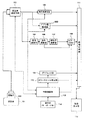
本発明を適用した超音波診断装置及び超音波撮像方法の実施形態について図面を参照して説明する。図1は、本実施形態の超音波診断装置のブロック図である。図2は、図1の制御演算部の構成を示す図である。 Embodiments of an ultrasonic diagnostic apparatus and an ultrasonic imaging method to which the present invention is applied will be described with reference to the drawings. FIG. 1 is a block diagram of the ultrasonic diagnostic apparatus of the present embodiment. FIG. 2 is a diagram illustrating a configuration of the control calculation unit of FIG.
図1及び図2に示すように、超音波診断装置は、被検体101との間で超音波を送受する超音波探触子(以下、探触子102という)と、探触子102に送波用の駆動信号を供給すると共に探触子102から出力される受信信号を処理する超音波送受信部103と、超音波送受信部103の出力信号から計測される生体組織の変位に基づき弾性画像を構成する弾性画像構成手段と、弾性画像を表示する表示手段としての画像表示器112などを備えている。ここでの弾性画像構成手段は、変位演算部105、歪み演算部106、弾性率演算部107、カラーディジタルスキャンコンバータ108(以下、カラーDSC108)などから構成されている。また、超音波送受信部103や弾性画像構成手段などに制御指令を出力する制御演算部113が設けられている。
As shown in FIGS. 1 and 2, the ultrasonic diagnostic apparatus transmits an ultrasonic probe (hereinafter referred to as a probe 102) that transmits / receives ultrasonic waves to / from a
そして、本実施形態の超音波診断装置に適用する制御演算部113は、図2に示すように、変位探索方向の設定手段113Bが実装されている。変位探索方向の設定手段113Bは、弾性画像を撮像するに際し、被検体101の生体組織の変位を計測する弾性演算方向(以下、変位探索方向という)を生体組織が実際に変位した方向(以下、組織変位方向という)に合わせて設定する。次いで、変位探索方向の設定手段113Bは、設定後の変位探索方向における生体組織の変位を弾性画像構成手段に計測させる。
And the
これにより、変位探索方向が組織変位方向に対してずれている場合でも、変位探索方向を組織変位方向に一致させることができる。したがって、生体組織が実際に変位した方向に沿って変位を計測することになるから、計測値の精度が向上する。このような計測値に基づいて弾性画像を構成することにより、生体組織の性状を忠実に弾性画像に現すことができる。 Thereby, even when the displacement search direction is deviated from the tissue displacement direction, the displacement search direction can be matched with the tissue displacement direction. Accordingly, since the displacement is measured along the direction in which the living tissue is actually displaced, the accuracy of the measurement value is improved. By constructing an elastic image based on such measurement values, the properties of the living tissue can be faithfully shown in the elastic image.
より詳細に本実施形態の超音波診断装置について説明する。超音波診断装置は、超音波送受系、断層像撮像系、弾性画像撮像系、表示系、制御系に大別される。 The ultrasonic diagnostic apparatus according to this embodiment will be described in more detail. Ultrasonic diagnostic apparatuses are roughly classified into an ultrasonic transmission / reception system, a tomographic imaging system, an elastic imaging system, a display system, and a control system.
超音波送受系は、探触子102と超音波送受信部103を備えている。探触子102は、機械的又は電子的にビーム走査を行うことによって被検体101との間で超音波を送受する超音波送受面を有する。超音波送受面は、複数の振動子が並べて配設されている。各振動子は、電気信号と超音波とを相互に変換する。また、探触子102は、超音波送受面に圧力センサが配設されている。圧力センサは、超音波送受面に加えられた圧力を検出して圧力計測部に出力する。圧力計測部は、歪み演算部106や弾性率演算部107に圧力データを出力する。
The ultrasonic transmission / reception system includes a
超音波送受信部103は、図2に示すように、探触子102に送受信手段121を介して送波用の駆動信号(パルス)を供給する送信手段120と、探触子102から送受信手段121を介して出力される受信信号を処理する受信手段122とを有する。
As shown in FIG. 2, the ultrasonic transmission /
超音波送受信部103の送信手段120は、探触子102の振動子を駆動して超音波を発生させる駆動信号としての送波パルスを設定間隔で送信する回路や、探触子102から射出される超音波送波ビームの収束点の深度を設定する回路を有する。ここで本実施形態の送信手段120は、送受信手段121を介してパルスを供給する振動子群を選択すると共に、探触子102から送信される超音波ビームが組織変位方向に走査するように、送波パルスの発生タイミングを制御する。すなわち、送信手段120は、該パルス信号の遅延時間を制御することにより、超音波ビームの走査方向を制御するようになっている。
The transmission means 120 of the ultrasonic transmission /
超音波送受信部103の受信手段122は、探触子102から送受信手段121を介して出力される信号に対して所定のゲインで増幅してRF信号すなわち受エコー信号を生成する回路や、RF信号の位相を整相加算してRF信号データを時系列に生成する回路を有する。このような受信手段122は、送受信手段121を介して探触子102から送信された超音波ビームによって取得した受信エコー信号に所定の遅延時間を与え位相を揃えて整相加算する。
The
断層像撮像系は、断層像構成部104を備えている。断層像構成部104は、信号処理部や白黒スキャンコンバータを有する。信号処理部は、超音波送受信部103から出力されたRF信号に対し画像処理を施すことによって、被検体101に関する濃淡断層像データ(例えば、白黒断層像データ)を構成する。ここでの画像処理は、ゲイン補正、ログ圧縮、検波、輪郭強調、フィルタ処理などである。白黒スキャンコンバータは、フレームメモリに格納された被検体101に関する断層像データをフレーム単位で読出し、読み出した断層像データをテレビ同期で出力する。ここでの白黒スキャンコンバータは、信号処理部から出力された断層像データをディジタル信号に変換するA/D変換器と、ディジタル化された複数の断層像データを時系列に記憶するフレームメモリと、フレームメモリから断層像データを読み出す指令を出力する制御コントローラを有する。
The tomographic image capturing system includes a tomographic
弾性画像撮像系は、超音波送受信部103の出力側から分岐して設けられた変位演算部105と、歪み演算部106と、弾性率演算部107と、カラーDSC108とを備えている。
The elastic image capturing system includes a
変位演算部105は、超音波送受信部103から出力されるRF信号データに基づき被検体101の生体組織の変位を計測する。この変位演算部105は、RF信号選択部と、計算部と、フィルタ部とを有する。
The
変位演算部105のRF信号選択部は、フレームメモリと選択部とを有する。このRF信号選択部は、超音波送受信部103から出力された時系列のRF信号データをフレームメモリに格納し、格納後のRF信号フレームデータ群から1組すなわち2つのRF信号フレームデータを選択部により選択する。より具体的には、RF信号選択部は、画像フレームレートに従って超音波送受信部103から出力される時系列のRF信号データをフレームメモリに順次確保する。そしてRF信号選択部は、制御演算部113から出力された指令に応じ、フレームメモリに格納されたRF信号データ群の中から第1のデータとしてのRF信号フレームデータ(N)を選択する。次いで、RF信号選択部は、制御演算部113から出力された指令に応じ、フレームメモリに格納されたRF信号データ群の中から第2のデータとしてのRF信号フレームデータ(X)を選択する。ここでのRF信号フレームデータ(X)は、RF信号フレームデータ(N)よりも時間的に過去にフレームメモリに格納されたRF信号フレームデータ群(N−1,N−2,N−3,…N−M)の中から選択されたものである。なお、N、M、Xは、RF信号フレームデータに関連付けられたインデックス番号としての自然数である。
The RF signal selection unit of the
変位演算部105の計算部は、1組のRF信号フレームデータから生体組織の変位探索方向における変位を求める。より具体的には、その計算部は、RF信号選択部により選択された第1のRF信号フレームデータ(N)と第2のRF信号フレームデータ(X)との間で一次元又は二次元の相関処理を実行する。例えば、計算部は、相関処理としてブロックマッチング法を適用することによって、断層像の各ピクセルに対応する生体組織の変位探索方向における変位や移動ベクトル(以下、変位と総称する)を求める。ここでの移動ベクトルとは、変位の方向と大きさに関する一次元又は二次元変位分布である。ブロックマッチング法とは、画像を例えばN×N画素からなるブロックに分け、関心領域内のブロックに着目し、着目後のブロックに近似するブロックを時間的に過去のフレームから探し、これを参照して予測符号化すなわち差分により標本値を決定する処理である。
The calculation unit of the
なお、変位演算部105のフィルタ部は、変位計算部から出力された生体組織の変位のばらつきを平準化するフィルタ回路を有し、後段の信号処理をスムースに実行するための前処理を施す。
The filter unit of the
歪み演算部106は、変位演算部105から出力された生体組織の移動量例えば変位ΔLを空間微分して生体組織の歪みデータ(S=ΔL/ΔX)を算出する。また、弾性率演算部107は、圧力変化を変位の変化で除することによって生体組織の弾性率データを算出する。例えば、弾性率演算部107は、探触子102の超音波送受面に加えられた圧力ΔPを圧力計測部から取得する。次いで、弾性率演算部107は、圧力ΔPと変位ΔLに基づき弾性率データとして例えばヤング率Ym(Ym=(ΔP)/(ΔL/L)を求める。このように弾性率演算部107は、断層像の各点に対応して弾性率データをそれぞれ求めることによって二次元の弾性画像データを取得する。なお、ヤング率とは、物体に加えられた単純引張り応力と、引張りに平行に生じるひずみに対する比である。また、歪みデータと弾性率データを含めて弾性データと適宜総称し、フレーム単位の弾性データを弾性フレームデータと適宜称する。
The
カラーDSC108は、歪み演算部106又は弾性率演算部107から出力された弾性データに基づき、被検体101の生体組織に関するカラー弾性画像を構成する。例えば、カラーDSC108は、弾性データ処理部と、カラースキャンコンバータと、フレームメモリを有する。弾性データ処理部は、歪み演算部106又は弾性率演算部107から出力される弾性フレームデータをフレームメモリに格納する。弾性データ処理部は、制御演算部113から出力された指令に応じ、フレームメモリから読み出した弾性フレームデータに対して画像処理を施す。
The
カラーDSC108のカラースキャンコンバータは、弾性データ処理部から出力された弾性フレームデータに対し、カラーマップに基づき色調変換処理を実行する色調変換部である。ここでのカラーマップは、弾性データの大きさに対し、光の3原色つまり赤(R)、緑(G)、青(B)で定まる色相情報を関連付けたものである。なお、赤(R)、緑(G)、青(B)のそれぞれは256階調を有し、255の階調に近づくにつれて大輝度に表示されるし、ゼロの階調に近づくにつれて低輝度に表示される。
The color scan converter of the
例えば、カラーDSC108のカラースキャンコンバータは、弾性データ処理部から出力された歪みデータが小さいときに赤色コードに変換するとともに、歪みデータが大きいときは青色コードに変換してフレームメモリに格納する。そして、カラースキャンコンバータは、制御指令に応じ、フレームメモリから弾性フレームデータをテレビ同期で読み出して画像表示器112に表示させる。ここでの色調変換後の弾性フレームデータに基づいた弾性画像は、生体組織の硬い部位(例えば、腫瘍)が赤色系に描画されるとともに、硬い部位の周辺部位が青色系に描画されたものになる。そのような弾性画像を視認することにより、例えば腫瘍の広がりや大きさを視覚的に把握できる。なお、カラーDSC108は、制御演算部113を介してキーボードなどの操作部114が接続されている。操作部114を介して入力された指令に応じ、カラーDSC108は、カラーマップの色合いなどを変更できる。
For example, the color scan converter of the
表示系は、グラフィック部109と、カラースケール発生部110と、画像合成部111と、画像表示器112などを備えている。グラフィック部109は、断層像や弾性画像以外の画像(例えば、画面のフレームワークやグラフィカルユーザインターフェース)を生成する。カラースケール発生部110は、色相の変化が段階を追って表示されたカラースケールを生成する。ここでのカラースケールは、カラーDSC108のカラーマップに対応させることができる。
The display system includes a
画像合成部111は、断層像構成部104から出力された断層像と、カラーDSC108から出力された弾性画像と、グラフィック部109から出力された画像と、カラースケール発生部110から出力されたカラースケールとを合成して1つの超音波像を生成する。例えば、画像合成部111は、フレームメモリと、画像処理部と、画像選択部とを有する。ここでのフレームメモリは、断層像構成部104から出力された断層像や、カラーDSC108から出力された弾性画像や、グラフィック部109から出力されたフレームワーク画像や、カラースケール発生部110から出力されたカラースケールを格納する。画像処理部は、制御指令に応じ、フレームメモリから断層像や弾性画像を読出し、断層像や弾性画像の同一座標系で相互に対応する画素に対し、その各画素の輝度情報や色相情報を設定割合で加算して合成する。すなわち、画像処理部は、断層像上に弾性画像を同一座標系で相対的に重畳させる。画像選択部は、制御指令に応じ、フレームメモリに格納された画像群のうちから画像表示器112に表示させる画像を選択する。画像表示器112は、画像合成部111から出力された画像データを表示するモニタなどを有する。
The
制御系は、図2に示すように、制御演算部113と操作部114などを備えている。制御演算部113は、基本制御手段113Aと、変位探索方向の設定手段113Bと、組織変位方向の検出手段113Cと、関心領域の設定手段113Dと、関心領域の角度補正手段113Eと、ガイド情報の生成手段113Fとを有する。
As shown in FIG. 2, the control system includes a
基本制御手段113Aは、超音波送受系、断層像撮像系、弾性画像撮像系、表示系に各種の制御指令を出力する。変位探索方向の設定手段113Bは、変位探索方向が組織変位方向に対してずれているときに、変位探索方向を組織変位方向に合わせて再設定する。ここでの変位探索方向は、被検体101の生体組織の変位を計測する際の基準とすべき弾性データ演算方向である。組織変位方向の検出手段113Cは、被検体101の生体組織に圧力が加えられた際に生体組織が実際に変位した組織変位方向を検出する。関心領域の設定手段113Dは、操作部114を介して入力された指令に応じ、画像表示器112に表示された断層像に関心領域(ROI: Region Of Interest)を設定する。関心領域の角度補正手段113Eは、設定手段113Dによって設定された関心領域を回転させることにより、関心領域の設定角度を補正する。ガイド情報の生成手段113Fは、変位探索方向が組織変位方向に一致するときの探触子102の傾きを示す誘導情報などを生成して画像表示器112に表示させる。なお、操作部114は、各種設定用のインターフェースとしてのキーボードやポインティングデバイスなどを有している。
The basic control means 113A outputs various control commands to the ultrasonic transmission / reception system, tomographic imaging system, elastic imaging system, and display system. The displacement search direction setting unit 113B resets the displacement search direction according to the tissue displacement direction when the displacement search direction is deviated from the tissue displacement direction. The displacement search direction here is an elasticity data calculation direction that should be used as a reference when measuring the displacement of the living tissue of the subject 101. The tissue displacement direction detection means 113C detects the tissue displacement direction in which the living tissue is actually displaced when pressure is applied to the living tissue of the subject 101. The region-of-interest setting unit 113D sets a region of interest (ROI) in the tomographic image displayed on the
ここで本実施形態の制御演算部113について図面を参照してより詳細に説明する。
Here, the
<実施例1>
本実施例は、組織変位方向を半自動で指定し、その組織変位方向に合わせて設定した変位探索方向に超音波ビームを偏向する例である。図3は、変位探索方向と組織変位方向との間にずれが生じている形態を示す模式図である。図4は、変位探索方向を組織変位方向に合わせた形態を示す模式図である。
<Example 1>
In this embodiment, the tissue displacement direction is specified semi-automatically, and the ultrasonic beam is deflected in the displacement search direction set in accordance with the tissue displacement direction. FIG. 3 is a schematic diagram illustrating a form in which a deviation occurs between the displacement search direction and the tissue displacement direction. FIG. 4 is a schematic diagram showing a form in which the displacement search direction is matched to the tissue displacement direction.
図3に示すように、被検体101の例えば体表に、探触子102の超音波送受面201aが接触している。ここでの変位探索方向206a〜206hは、探触子102で送受される超音波ビーム方向、すなわち超音波送受面201aに対してほぼ垂直方向に初期設定されている。また、被検体101内の脈管(血管)204は、超音波送受面201aに対して傾斜して直線状に存在するものとしている。そして、弾性画像を取得すべき生体組織の関心領域203は、図の点線で示すように、超音波送受面201aに対して長辺部がほぼ平行な矩形つまり長方形に設定されている。なお、ここでの関心領域203は、操作部114を介して入力された指令に応じ、画像表示器112に表示された断層像上に設定されたものである。
As shown in FIG. 3, the ultrasonic transmission /
図3に示す形態においては、脈管204の周期的な拍動によって、脈管204の周辺組織が圧迫される。その周辺組織のうち関心領域203内の生体組織の変位が、変位演算部105により計測される。変位の計測値に基づいて、弾性データが歪み演算部106や弾性率演算部107により算出される。そして、弾性データの算出値に基づいて、弾性画像がカラーDSC108により構成される。
In the form shown in FIG. 3, the tissue around the
しかし、図3に示す例では、関心領域203内の生体組織の変位を計測するに際し、変位探索方向206a〜206hは、超音波ビーム方向つまり関心領域203の短手方向であるのに対し、脈管204の拍動に由来する組織変位方向205a〜205jは、脈管204の径方向である。したがって、変位探索方向206a〜206hと組織変位方向205a〜205jが所定の角度で交差している。すなわち、変位探索方向206a〜206hと組織変位方向205a〜205jとの間にずれが生じている。このような状態で生体組織の変位を計測すると、例えば前記ずれを補正する演算精度の制限に起因して、変位の計測値に誤差が含まれるおそれがある。
However, in the example shown in FIG. 3, when measuring the displacement of the living tissue in the region of
そこで、本実施例は、関心領域203の角度を半自動で補正することによって組織変位方向に合わせて変位探索方向を指定する。より具体的には、図3に示すように、操作者は、画像表示器112に表示された断層像を視認しながら、操作部114を介して、脈管204の上側縁部と関心領域203の短辺部が交わる二箇所のそれぞれに基準点(以下、交差点207、208という)を指定する。なお、脈管204の上側縁部に代えて、下側縁部における短辺部との交差点を指定してもよい。また、交差点207、208は、断層像の輝度を利用して設定してもよい。すなわち、画像表示器112の画面中で脈管204の壁面は、その輝度が高く表示される。制御演算部113は、この輝度特性を利用し、脈管204の壁面に形成される高輝度ラインと関心領域203との交点を交差点207、208として設定する。
Thus, in this embodiment, the displacement search direction is designated in accordance with the tissue displacement direction by correcting the angle of the region of
交差点207、208が指定されると、図4に示すように、組織変位方向の検出手段113Cは、交差点207、208間を結ぶ線分に直交する方向を組織変位方向と判定する。すなわち、本実施例は、交差点207、208を指定することによって組織変位方向を半自動的に検出する。
When the
そして、関心領域の角度補正手段113Eは、交差点207、208間を結ぶ線分に直交する方向と関心領域203の短手方向とのずれがゼロになるように、関心領域203を回転補正する。すなわち、関心領域の角度補正手段113Eは、交差点207、208間を結ぶ線分に直交する方向に短手方向が合致する関心領域308を再設定する。次いで、変位探索方向の設定手段113Bは、変位探索方向206a〜206hを関心領域308の短手方向に合わせて補正することによって、新たな変位探索方向306a〜306fを指定する。超音波送受信部103は、変位探索方向306a〜306fに合わせて超音波ビームを偏向する。そして、変位演算部105は、変位探索方向306a〜306fに沿って羅列された受信信号に基づき、変位探索方向306a〜306fにおける生体組織の変位を計測する。
Then, the region of interest angle correction unit 113E rotationally corrects the region of
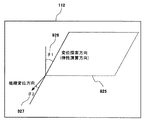
図5は、変位探索方向を組織変位方向に合わせた際の生体組織の変位を計測する例を示す図である。図5に示す関心領域501は、関心領域の角度補正手段113Eにより元の関心領域を角度補正した平行四辺形のものである。ここでの組織変位方向は、関心領域501の傾斜側辺に沿った方向、つまり関心領域501に矢印で図示した方向である。変位探索方向は、変位探索方向の設定手段113Bにより関心領域501の傾斜側辺に沿った方向に再設定される。要するに、ここでの関心領域501においては、変位探索方向が組織変位方向に一致している。
FIG. 5 is a diagram illustrating an example of measuring the displacement of the biological tissue when the displacement search direction is matched with the tissue displacement direction. The region of
まず、超音波送受信部103は、探触子102を介して変位探索方向に合わせて超音波ビームを送受することによって時系列に受信信号を取得する。次いで、変位演算部105は、現在取得されたRF信号フレームデータ(N)502を第1のデータとして選択する。ここでのRF信号フレームデータ(N)502は、関心領域501の側辺の傾斜方向、つまり変位探索方向に従って羅列された信号群である。変位演算部105は、時間的に過去に取得されたRF信号フレームデータ(X)503も選択する。ここでのRF信号フレームデータ(X)503も、関心領域501の側辺の傾斜方向、つまり変位探索方向に従って羅列された信号群である。そして、変位演算部105は、RF信号フレームデータ(N)502とRF信号フレームデータ(X)503に対して相関処理を実行することによって、変位探索方向における生体組織の移動分すなわち変位量を計測する。
First, the ultrasonic transmission /
本実施例によれば、図2及び図3に代表されるように、変位探索方向206a〜206hが組織変位方向205a〜205jに対してずれている場合、組織変位方向205a〜205jに合わせた変位探索方向306a〜306fが再設定される。したがって、変位探索方向306a〜306fに沿って生体組織の変位を計測すると、生体組織が実際に変位した方向に沿って変位を計測することになるから、変位の計測値の精度が向上する。このような計測値に基づいて弾性画像を構成することにより、弾性画像に生じるアーチファクトが低減される。その結果、生体組織を圧迫する方向や生体組織を圧迫する面の形状などに左右されずに、生体組織の歪みや硬さなどの性状を忠実に現わした高品質の弾性画像を取得できる。
According to the present embodiment, as typified by FIGS. 2 and 3, when the
例えば、甲状腺部位は、頸動脈の拍動に由来して周辺組織が歪みことは知られている。したがって、甲状腺部位に関する弾性像を撮像する際は、頸動脈の拍動によって歪んだ周辺組織の変位を計測し、変位の計測値に基づいて弾性像を構成できることになる。しかし、探触子102の超音波送受面に対して頸動脈が傾斜して存在するなど、変位探索方向と組織変位方向との間にずれが生じる場合がある。この点、本実施例によれば、変位探索方向を組織変位方向に一致させることにより、生体組織の変位の計測精度を向上させることができるため、有用な臨床データを取得できる。
For example, it is known that the surrounding tissue is distorted in the thyroid region due to the pulsation of the carotid artery. Therefore, when an elastic image related to the thyroid region is captured, the displacement of the surrounding tissue distorted by the pulsation of the carotid artery can be measured, and the elastic image can be constructed based on the measured value of the displacement. However, there may be a deviation between the displacement search direction and the tissue displacement direction, for example, the carotid artery is inclined with respect to the ultrasonic transmission / reception surface of the
図6は、種々の脈管に対する関心領域の設定状態の例を示す図である。図6(A)及び図6(C)は、超音波送受面に対して脈管が傾斜して存在する形態を示す。この場合の関心領域(ROI)は、その短手方向が脈管の長手方向に対して垂直になるように設定されている。そして、関心領域の短手方向つまり組織変位方向に合致させて変位探索方向が設定されている。すなわち、変位探索方向と組織変位方向が一致している。なお、図6(C)に示す場合は、脈管が図6(A)に示す脈管に対して逆方向に傾いているので、図6(A)の場合に対して逆方向に関心領域を回転補正することによって、変位探索方向を組織変位方向に合わせることになる。図6(B)は、超音波送受面に対して脈管が平行に存在する形態を示す。この場合は、関心領域の短手方向つまり変位探索方向が組織変位方向と一致するので、関心領域の角度補正は不要である。 FIG. 6 is a diagram illustrating an example of a state of interest setting for various vessels. 6 (A) and 6 (C) show a form in which the vasculature is inclined with respect to the ultrasonic transmission / reception surface. In this case, the region of interest (ROI) is set so that its short direction is perpendicular to the longitudinal direction of the vessel. The displacement search direction is set in accordance with the short direction of the region of interest, that is, the tissue displacement direction. That is, the displacement search direction matches the tissue displacement direction. In the case shown in FIG. 6C, the region of interest is opposite to the case shown in FIG. 6A because the vessel is inclined in the opposite direction to the vessel shown in FIG. , The displacement search direction is matched with the tissue displacement direction. FIG. 6B shows a form in which the vasculature is parallel to the ultrasonic transmission / reception surface. In this case, since the short direction of the region of interest, that is, the displacement search direction coincides with the tissue displacement direction, angle correction of the region of interest is unnecessary.
また、図6(D)は、超音波送受面に対して脈管が湾曲して存在する形態を示す。この場合、関心領域は、脈管の曲部の曲率に対応した弧を有する扇形に設定される。変位探索方向の設定手段113Bは、関心領域の弧の接線に垂直になる方向を変位探索方向として再設定する。超音波送受信部103は、関心領域の弧に応じて超音波ビーム方向を徐々に変更しながら超音波ビームを送受させる。これによって、超音波送受面に対して脈管が湾曲して存在する場合でも、脈管の湾曲に由来する組織変位方向の変化に追従して変位探索方向を合わせることができる。
FIG. 6D shows a form in which a vascular curve is present with respect to the ultrasonic transmission / reception surface. In this case, the region of interest is set in a sector shape having an arc corresponding to the curvature of the curved portion of the vessel. The displacement search direction setting means 113B resets the direction perpendicular to the arc tangent of the region of interest as the displacement search direction. The ultrasonic transmission /
この扇状の関心領域は、複数の微小矩形関心領域を繋いで生成される。例えば、図6(D)右図に示すように、図2,図3,図6(A)〜図6(C)と同様な手法を用いることにより、3つの微小矩形関心領域ROI1〜ROI3等の短手方向と脈管の接線方向とを一致させるとともに、長手方向と脈管の接線に垂直になる方向とを一致させて、脈管に沿って微小矩形関心領域ROI1〜ROI3が分割して複数設定される。このようにして扇状の関心領域全体に亘って複数の微小矩形関心領域が設定される。なお、この微小矩形関心領域は、脈管の曲率形状が無視できる範囲で設定されている。 This fan-shaped region of interest is generated by connecting a plurality of minute rectangular regions of interest. For example, as shown in the right diagram of FIG. 6D, three small rectangular regions of interest ROI1 to ROI3, etc. are obtained by using the same method as in FIGS. 2, 3, 6A to 6C. The rectangular directions of interest ROI1 to ROI3 are divided along the vessel by matching the short direction of the vessel and the tangential direction of the vessel, and the longitudinal direction and the direction perpendicular to the tangent of the vessel. Multiple settings are made. In this way, a plurality of minute rectangular regions of interest are set over the entire fan-shaped region of interest. Note that the minute rectangular region of interest is set in a range where the curvature shape of the vessel can be ignored.
そして、それぞれの微小矩形関心領域ROI1,ROI2,ROI3等の長手方向つまり組織変位方向に合致させて変位探索方向が設定される。これによって各微小矩形関心領域において変位探索方向と組織変位方向を一致させることができる。つまり、扇状の関心領域全体に亘って変位探索方向と組織変位方向を一致させることができる。このような関心領域の設定手法によれば、脈管の形状は扇状に限らず、複雑な形状でも対応できる。 Then, the displacement search direction is set in accordance with the longitudinal direction of each small rectangular region of interest ROI1, ROI2, ROI3, etc., that is, the tissue displacement direction. Accordingly, the displacement search direction and the tissue displacement direction can be matched in each minute rectangular region of interest. That is, the displacement search direction and the tissue displacement direction can be matched over the entire fan-shaped region of interest. According to such a region-of-interest setting method, the shape of a vascular vessel is not limited to a fan shape, and a complex shape can be handled.
なお、本例では、脈管204の拍動を圧力源とし、脈管204の拍動によって圧迫された際の生体組織の弾性画像を取得しているが、このような形態に限れたものではない。例えば、被検体101の体表に接触させた探触子102を手動で押付けて圧迫する形態や、被検体101の体表に接触させたバイブレータで圧迫する形態でも本発明を適用できる。要するに、変位探索方向と組織変位方向との間にずれが生じる場合に本発明を適用すればよい。
In this example, the pulsation of the vascular 204 is used as a pressure source, and an elastic image of the living tissue when compressed by the pulsation of the vascular 204 is acquired. However, the present invention is not limited to such a form. Absent. For example, the present invention can be applied to a form in which the
<実施例2>
本実施例は、変位探索方向を組織変位方向に合わせるに際し、関心領域内に予め定められた弾性演算方向つまり関心領域内の変位探索方向だけを組織変位方向に合わせる点で、超音波ビーム自体を偏向させた実施例1と相違する。したがって、その相違点を中心に説明する。
<Example 2>
In this embodiment, when the displacement search direction is adjusted to the tissue displacement direction, the ultrasonic beam itself is adjusted in that only the elastic calculation direction predetermined in the region of interest, that is, the displacement search direction in the region of interest is adjusted to the tissue displacement direction. This is different from the deflected
図7は、本実施例の変位探索方向の設定手段113Bの動作を説明するための図である。図7に示す形態は、超音波ビームの射出方向が超音波送受面201aに対して垂直なままである点で、図4に示す形態と異なる。
FIG. 7 is a diagram for explaining the operation of the displacement search direction setting means 113B of the present embodiment. The form shown in FIG. 7 differs from the form shown in FIG. 4 in that the emission direction of the ultrasonic beam remains perpendicular to the ultrasonic transmission /
被検体101の生体組織の弾性画像を撮像するに際しては、まず、超音波送受信部103は、超音波送受面201aに対して垂直に超音波ビームを送受することによって被検体101に関する信号を取得する。ここで、本実施例の変位探索方向の設定手段113Bは、関心領域303に予め設定された変位探索方向を組織変位方向205a〜205jに合わせて設定する。そして、変位探索方向の設定手段113Bは、超音波送受信部103から出力される信号のうち前記補正後の変位探索方向に対応して羅列した信号を選択させる指令と、選択後の信号に基づき生体組織の変位探索方向における変位を計測させる指令を変位演算部105に出力する。
In capturing an elastic image of the biological tissue of the subject 101, first, the ultrasonic transmission /
すなわち、超音波送受信部103の出力信号から組織変位方向205a〜205jに対応した信号を選択して弾性演算を実行すると、関心領域303内の変位探索方向だけを組織変位方向に合わせたことになる。したがって、本実施例によれば、変位探索方向を組織変位方向に合わせるに際し、超音波ビームを偏向させずとも、関心領域303における変位探索方向を組織変位方向に合わせることができる。その結果、実施例1と同様な効果に加え、生体組織の複雑な動きに応じて変位探索方向を組織変位方向に合わせることが簡単になる。
That is, when the elasticity calculation is performed by selecting signals corresponding to the
<実施例3>
本実施例は、組織変位方向を自動に検出する点で、組織変位方向を半自動で指定する実施例1と相違する。したがって、その相違点を中心に説明する。
<Example 3>
The present embodiment is different from the first embodiment in which the tissue displacement direction is semi-automatically specified in that the tissue displacement direction is automatically detected. Therefore, the difference will be mainly described.
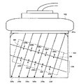
図8は、図2の組織変位方向の検出手段113Cの動作の例を示す概念図である。図8の横軸は、超音波送受面201aに対してほぼ平行な方向の被検体座標軸を示している。縦軸は、超音波送受面201aに対してほぼ垂直な方向の被検体座標軸を示している。横軸及び縦軸のそれぞれの単位はミリメートル(mm)である。
FIG. 8 is a conceptual diagram showing an example of the operation of the tissue displacement direction detection means 113C of FIG. The horizontal axis in FIG. 8 indicates the subject coordinate axis in a direction substantially parallel to the ultrasonic transmission /
図8に示すように、組織変位方向の検出手段113Cは、生体組織に圧力を加える前と後の断層像に対し、各ピクセルに対応する信号に基づき広範囲にわたって相関演算を実行する。より具体的には、検出手段113Cは、生体組織に圧力を加える前の信号601を取得する。ここでの信号601は、縦方向に1[mm]で横方向に1[mm]の位置にあるものとする。そして、検出手段113Cは、生体組織に圧力が加えられた際の信号601の移動先を相関処理によって検出し、検出結果に基づき組織変位方向を判定する。 As shown in FIG. 8, the tissue displacement direction detection means 113C performs a correlation calculation over a wide range on the tomographic images before and after applying pressure to the living tissue based on signals corresponding to each pixel. More specifically, the detection unit 113C acquires the signal 601 before applying pressure to the living tissue. The signal 601 here is assumed to be at a position of 1 [mm] in the vertical direction and 1 [mm] in the horizontal direction. The detection unit 113C detects the movement destination of the signal 601 when pressure is applied to the living tissue by correlation processing, and determines the tissue displacement direction based on the detection result.
例えば、検出手段113Cは、信号601の移動先を信号602の位置(縦方向8[mm]、横方向1[mm])に検出したときは、組織変位方向は縦方向(例えば0度)であると判定する。また、検出手段113Cは、信号601の移動先を信号603の位置(縦方向1[mm]、横方向8[mm])に検出したときは、組織変位方向は横方向(例えば90度)であると判定する。また、検出手段113Cは、信号601の移動先を信号604の位置(縦方向8[mm]、横方向8[mm])に検出したときは、組織変位方向は斜め方向(例えば45度)であると判定する。検出手段113Cは、組織変位方向の検出処理を座標ごとに実行し、各座標の検出値を平均した値を組織変位方向として検出する。その組織変位方向は、関心領域の角度補正手段113Eや変位探索方向の設定手段113Bに出力される。なお、変位探索方向を組織変位方向に合わせて生体組織の変位を計測する処理は、実施例1と同様である。 For example, when the detection unit 113C detects the movement destination of the signal 601 at the position of the signal 602 (vertical direction 8 [mm], horizontal direction 1 [mm]), the tissue displacement direction is the vertical direction (for example, 0 degrees). Judge that there is. When the detection unit 113C detects the movement destination of the signal 601 at the position of the signal 603 (vertical direction 1 [mm], horizontal direction 8 [mm]), the tissue displacement direction is the horizontal direction (for example, 90 degrees). Judge that there is. When the detection unit 113C detects the destination of the signal 601 at the position of the signal 604 (vertical direction 8 [mm], horizontal direction 8 [mm]), the tissue displacement direction is an oblique direction (for example, 45 degrees). Judge that there is. The detection unit 113C executes a tissue displacement direction detection process for each coordinate, and detects a value obtained by averaging the detected values of each coordinate as the tissue displacement direction. The tissue displacement direction is output to the region of interest angle correction unit 113E and the displacement search direction setting unit 113B. The process of measuring the displacement of the living tissue by matching the displacement search direction to the tissue displacement direction is the same as that of the first embodiment.
すなわち、甲状腺などの弾性画像を撮像する際、甲状腺の組織に対して縦方向に圧力を加えても組織が横方向に変位することがあるなど、組織変位方向の把握が困難な場合がある。この点、本実施例によれば、組織変位方向を客観的かつ定量的に自動検出できるため、生体組織の変位の計測精度をより一層高めることができる。 That is, when an elastic image of the thyroid gland is taken, it may be difficult to grasp the tissue displacement direction, for example, the tissue may be displaced laterally even when pressure is applied to the thyroid tissue in the longitudinal direction. In this respect, according to the present embodiment, the tissue displacement direction can be automatically detected objectively and quantitatively, and therefore the measurement accuracy of the displacement of the living tissue can be further enhanced.
<実施例4>
本実施例は、組織変位方向を自動検出するに際し、血管の血流方向を利用する点で実施例3と相違する。したがって、相違点を中心に説明する。
<Example 4>
The present embodiment is different from the third embodiment in that the blood flow direction of the blood vessel is used when the tissue displacement direction is automatically detected. Therefore, the difference will be mainly described.
本実施例の超音波診断装置は、図1に示すように、ドプラ像構成部900が設けられている。ドプラ像構成部900は、超音波送受信部103から取り込んだ時系列の受信信号に基づきドプラ偏位を演算し、そのドプラ偏位からドプラ像(例えば、カラー血流像)を構成する。そして、本実施例の変位探索方向の設定手段113Bは、ドプラ像構成部900によって判定可能な血流方向に基づき、組織変位方向に一致する変位探索方向を決定する。
As shown in FIG. 1, the ultrasonic diagnostic apparatus of this embodiment is provided with a Doppler
図9は、本実施例の変位探索方向の設定手段113Bの動作を説明するための図である。まず、図9Aは、カラー血流像が図3の脈管204に重畳して表示された図である。ここでのカラー血流像は、ドプラ像構成部900から画像合成部111を介して画像表示器112に出力されたものである。
FIG. 9 is a diagram for explaining the operation of the displacement search direction setting means 113B of this embodiment. First, FIG. 9A is a diagram in which a color blood flow image is displayed superimposed on the
図9Bは、血流方向に基づき組織変位方向に合わせて変位探索方向を設定する形態を示す模式図である。組織変位方向の検出手段113Cは、図9Aに示すカラー血流像に基づき血流方向を検出し、その血流方向に直交する方向を組織変位方向と判定する。変位探索方向の設定手段113Bは、検出手段113Cにより判定された組織変位方向に合わせて変位探索方向を決定する。なお、関心領域303の設定処理又は回転補正処理や、変位探索方向に従って超音波ビーム方向を偏向する処理などは実施例1と同様である。また実施例2で説明したように、組織変位方向に合わせて関心領域303の変位探索方向を合わせる処理を適用してもよい。
FIG. 9B is a schematic diagram illustrating a form in which the displacement search direction is set in accordance with the tissue displacement direction based on the blood flow direction. The tissue displacement direction detection means 113C detects the blood flow direction based on the color blood flow image shown in FIG. 9A, and determines the direction orthogonal to the blood flow direction as the tissue displacement direction. The displacement search direction setting means 113B determines the displacement search direction in accordance with the tissue displacement direction determined by the detection means 113C. The processing for setting the region of
本実施例によれば、ドプラ血流像から検出可能な血流方向に基づき組織変位方向を自動判定できるため、組織変位方向に変位探索方向を合わせる作業が簡単になる。例えば、被検体101に血管が湾曲した複雑な形態で存在する場合でも、その血管に係るドプラ血流像に基づき変位探索方向を簡単に決めることができる。 According to the present embodiment, the tissue displacement direction can be automatically determined based on the blood flow direction that can be detected from the Doppler blood flow image, and therefore, the operation of matching the displacement search direction with the tissue displacement direction is simplified. For example, even when the subject 101 exists in a complicated shape with curved blood vessels, the displacement search direction can be easily determined based on the Doppler blood flow image relating to the blood vessels.
<実施例5>
本実施例は、変位探索方向を組織変位方向に合わせるに際し、探触子102の傾きを手動で調整する点で、探触子102で送受する超音波ビームを偏向させる実施例1と相違する。したがって、相違点を中心に説明する。
<Example 5>
The present embodiment is different from the first embodiment in which the ultrasonic beam transmitted and received by the
探触子102の傾きを変更すると、探触子102の超音波送受面201aの傾斜角度が変わるため、超音波送受面201aで送受される超音波ビームの方向を調整できることになる。すなわち、超音波ビーム方向に変位探索方向が設定されている場合、探触子102の傾きを調整することにより、変位探索方向を組織変位方向に合わせることができる。
When the inclination of the
ただし、探触子102の傾きを経験則や直感に頼って調整すると、変位探索方向を組織変位方向に合わせる作業が煩雑になる。そこで、図2のガイド情報の生成手段113Fは、変位探索方向が組織変位方向に一致するときの探触子102の傾斜方向や傾斜角度を示す誘導情報を生成して画像表示器112に表示させる。
However, when the inclination of the
図10は、探触子102の傾斜方向と傾斜角度を示すガイド情報の表示例である。なお、探触子102の位置や傾きをリアルタイムに検出する位置センサが配設されているものとする。ガイド情報の生成手段113Fは、例えば、図10に示すように、被検体101の体表に接触した探触子102の模式画像920と、探触子102の超音波ビーム方向に合致して設定された変位探索方向を示す矢印画像921と、被検体101の生体組織の組織変位方向を示す矢印画像922と、変位探索方向が組織変位方向に一致するときの探触子102の傾斜方向を示す誘導画像923とを生成して表示する。また、変位探索方向と組織変位方向とのずれに対応した補正角θを示す角度情報924を表示してもよい。ここでの補正角θも、探触子102の傾斜角度を示すガイド情報である。
FIG. 10 is a display example of guide information indicating the tilt direction and tilt angle of the
本実施例によれば、誘導画像923や角度情報924などのガイド情報は、探触子102の傾きを調整して変位探索方向と組織変位方向を合わせる作業を支援する客観的かつ定量的な指標になる。したがって、操作者は、探触子102の目標傾斜方向を視覚的に把握できるので、変位探索方向を組織変位方向に合わせる作業が的確かつ簡単に実施できる。その結果、生体組織の変位の計測精度が向上するとともに、装置の使い勝手が高まる。
According to the present embodiment, the guide information such as the
また、図11に示すように、ガイド情報の生成手段113Fは、変位探索方向と垂直方向(例えば、被検体101の深度方向)との間に形成される角度θ1を示す角度情報926と、変位探索方向と組織変位方向との間に形成される角度θ2を示す角度情報927などを関心領域925に並べて表示してもよい。これにより、操作者は、被検体101の関心領域925に対する変位探索方向と組織変位方向を相対的かつ視覚的に把握できる。
Further, as shown in FIG. 11, the generation unit 113F of the guide information, the displacement search direction and the vertical direction (e.g., the depth direction of the subject 101) and
以上、本実施形態によれば、生体組織を圧迫する方向や生体組織を圧迫する面の形状などに左右されずに、生体組織の歪みや硬さなどの性状を忠実に現わした高品質の弾性画像を簡単に取得できる。 As described above, according to the present embodiment, the high quality that faithfully displays the properties such as strain and hardness of the living tissue without depending on the direction of pressing the living tissue or the shape of the surface pressing the living tissue. Elastic images can be easily acquired.
なお、図1又は図2などに示すように、本実施形態の超音波撮像に必要な制御機能をブロック単位で説明したが、各制御機能を超音波撮像プログラムとして集約し、その超音波撮像プログラムを制御用コンピュータに実行させることもできる。例えば、超音波撮像プログラムは、被検体101の生体組織が変位する組織変位方向に合わせて変位の探索方向を設定する設定手順と、被検体101との間で超音波を送受する探触子102に送波用の駆動信号を供給する手順と、探触子102から出力される受信信号を処理する手順と、受信処理後の信号から前記探索方向の変位を計測する手順と、その変位の計測値に基づき弾性画像を構成する手順と、その弾性画像を表示する手順とを制御用コンピュータに実行させる。
In addition, as shown in FIG. 1 or FIG. 2 and the like, the control functions necessary for the ultrasonic imaging of the present embodiment have been described in units of blocks. However, the control functions are aggregated as an ultrasonic imaging program, and the ultrasonic imaging program Can be executed by the control computer. For example, the ultrasound imaging program sets a procedure for setting a search direction for displacement in accordance with a tissue displacement direction in which a living tissue of the subject 101 is displaced, and a
上述のとおり、本発明を適用した一実施形態の超音波診断装置を説明したが、本発明を適用した超音波診断装置は、その精神または主要な特徴から逸脱することなく、他の様々な形態で実施できる。そのため、前述の実施形態はあらゆる点で単なる例示に過ぎず、限定的に解釈されるものではない。すなわち、本発明の範囲は、均等範囲に属する変形や変更を含むものとする。
As described above, the ultrasonic diagnostic apparatus according to an embodiment to which the present invention is applied has been described. However, the ultrasonic diagnostic apparatus to which the present invention is applied may be various other forms without departing from the spirit or main features thereof. Can be implemented. Therefore, the above-mentioned embodiment is only a mere illustration in all points, and is not interpreted limitedly. That is, the scope of the present invention includes modifications and changes belonging to the equivalent range.
本発明の目的は、生体組織の変位の計測精度を向上して生体組織の性状をより忠実に現わした弾性画像を撮像することにある。 An object of the present invention is a more faithfully elastic image with Genwa improved by properties of biological tissues the measurement accuracy of the displacement of the biological tissue in the image pickup to Turkey.
上記目的を実現するために、本発明の超音波診断装置は、被検体との間で超音波を送受する超音波探触子と、該超音波探触子に送波用の駆動信号を供給する送信手段と、前記超音波探触子から出力される受信信号を処理する受信手段と、該受信手段の出力信号から計測される生体組織の変位に基づき弾性画像を構成する弾性像構成手段と、前記弾性画像を表示する表示手段とを備え、前記変位の探索方向が予め定められた関心領域を前記被検体の生体組織に対応して設定する関心領域設定手段と、前記関心領域の前記変位の探索方向に合わせて超音波ビームが偏向され、前記弾性像構成手段は前記探索方向の変位を前記関心領域における各点で計測して前記弾性画像を構成することを特徴とする。 In order to achieve the above object, an ultrasonic diagnostic apparatus of the present invention supplies an ultrasonic probe that transmits and receives ultrasonic waves to and from a subject, and a drive signal for transmission to the ultrasonic probe. Transmitting means for receiving, receiving means for processing a reception signal output from the ultrasonic probe, and elastic image forming means for forming an elastic image based on a displacement of a living tissue measured from an output signal of the receiving means; Display means for displaying the elasticity image, a region of interest setting means for setting a region of interest in which the search direction of the displacement is predetermined corresponding to the biological tissue of the subject, and the displacement of the region of interest The elastic beam is deflected in accordance with the search direction, and the elastic image forming means measures the displacement in the search direction at each point in the region of interest to form the elastic image.
本発明によれば、変位探索方向が予め定められた関心領域を設定し、その変位の探索方向に合わせて超音波ビームが偏向されるので、変位探索方向に沿って生体組織の変位を計測することにより、生体組織が実際に変位した方向に沿って変位を計測することになるから、計測値の精度が向上する。このような計測値に基づいて弾性画像を構成することにより、弾性画像に生じるアーチファクトが低減される。その結果、生体組織の性状を忠実に現わした高品質の弾性画像が取得される。 According to the present invention, the displacement search direction set a region of interest predetermined since the ultrasonic beam is deflected in accordance with the search direction of the displacement, measured displacement of the living tissue along the displacement of the search direction By doing so , since the displacement is measured along the direction in which the living tissue is actually displaced, the accuracy of the measurement value is improved. By constructing an elastic image based on such measurement values, artifacts generated in the elastic image are reduced. As a result, a high-quality elastic image that faithfully shows the properties of the living tissue is acquired.
本実施例によれば、図3及び図4に代表されるように、変位探索方向206a〜206hが組織変位方向205a〜205jに対してずれている場合、組織変位方向205a〜205jに合わせた変位探索方向306a〜306fが再設定される。したがって、変位探索方向306a〜306fに沿って生体組織の変位を計測すると、生体組織が実際に変位した方向に沿って変位を計測することになるから、変位の計測値の精度が向上する。このような計測値に基づいて弾性画像を構成することにより、弾性画像に生じるアーチファクトが低減される。その結果、生体組織を圧迫する方向や生体組織を圧迫する面の形状などに左右されずに、生体組織の歪みや硬さなどの性状を忠実に現わした高品質の弾性画像を取得できる。
According to the present embodiment, as represented by FIG. 3 and FIG. 4 , when the
例えば、甲状腺部位は、頸動脈の拍動に由来して周辺組織が歪むことは知られている。したがって、甲状腺部位に関する弾性像を撮像する際は、頸動脈の拍動によって歪んだ周辺組織の変位を計測し、変位の計測値に基づいて弾性像を構成できることになる。しかし、探触子102の超音波送受面に対して頸動脈が傾斜して存在するなど、変位探索方向と組織変位方向との間にずれが生じる場合がある。この点、本実施例によれば、変位探索方向を組織変位方向に一致させることにより、生体組織の変位の計測精度を向上させることができるため、有用な臨床データを取得できる。
For example, it is known that the surrounding tissue is distorted in the thyroid region due to the pulsation of the carotid artery. Therefore, when an elastic image related to the thyroid region is captured, the displacement of the surrounding tissue distorted by the pulsation of the carotid artery can be measured, and the elastic image can be constructed based on the measured value of the displacement. However, there may be a deviation between the displacement search direction and the tissue displacement direction, for example, the carotid artery is inclined with respect to the ultrasonic transmission / reception surface of the
この扇状の関心領域は、複数の微小矩形関心領域を繋いで生成される。例えば、図6(D)右図に示すように、図3,図4,図6(A)〜図6(C)と同様な手法を用いることにより、3つの微小矩形関心領域ROI1〜ROI3等の短手方向と脈管の接線方向とを一致させるとともに、長手方向と脈管の接線に垂直になる方向とを一致させて、脈管に沿って微小矩形関心領域ROI1〜ROI3が分割して複数設定される。このようにして扇状の関心領域全体に亘って複数の微小矩形関心領域が設定される。なお、この微小矩形関心領域は、脈管の曲率形状が無視できる範囲で設定されている。 This fan-shaped region of interest is generated by connecting a plurality of minute rectangular regions of interest. For example, as shown in the right diagram of FIG. 6D, three small rectangular regions of interest ROI1 to ROI3 etc. are obtained by using the same method as in FIGS . 3 , 4 , and 6A to 6C. The rectangular directions of interest ROI1 to ROI3 are divided along the vessel by matching the short direction of the vessel and the tangential direction of the vessel, and the longitudinal direction and the direction perpendicular to the tangent of the vessel. Multiple settings are made. In this way, a plurality of minute rectangular regions of interest are set over the entire fan-shaped region of interest. Note that the minute rectangular region of interest is set in a range where the curvature shape of the vessel can be ignored.
Claims (25)
前記生体組織が変位する組織変位方向に合わせて前記変位の探索方向を設定する変位探索方向設定手段を有し、前記弾性像構成手段は前記探索方向の変位を計測して前記弾性画像を構成することを特徴とする超音波診断装置。 Ultrasonic probe for transmitting / receiving ultrasonic waves to / from a subject, transmission means for supplying a driving signal for transmission to the ultrasonic probe, and a reception signal output from the ultrasonic probe An ultrasonic diagnostic apparatus comprising: a receiving unit that processes the elastic image; an elastic image forming unit that forms an elastic image based on a displacement of a living tissue measured from an output signal of the receiving unit; and a display unit that displays the elastic image In
Displacement search direction setting means for setting the search direction of the displacement according to the tissue displacement direction in which the living tissue is displaced, and the elastic image forming means measures the displacement in the search direction to form the elastic image. An ultrasonic diagnostic apparatus.
前記変位探索方向設定手段は、前記回転補正後の関心領域の前記探索方向に合わせて前記超音波ビームを偏向させる指令を前記送信手段又は前記受信手段に出力する請求項1に記載の超音波診断装置。 A region-of-interest setting means for setting a region of interest in which the search direction of the displacement is predetermined corresponding to the living tissue of the subject, and rotation correction of the region of interest to match the search direction with the tissue displacement direction An angle correction means for the region of interest;
2. The ultrasonic diagnosis according to claim 1, wherein the displacement search direction setting unit outputs a command to deflect the ultrasonic beam in accordance with the search direction of the region of interest after the rotation correction to the transmission unit or the reception unit. apparatus.
前記変位探索方向設定手段は、前記受信手段から出力される信号のうち前記回転補正後の関心領域の前記探索方向に対応して羅列した信号を選択させる指令と、該選択後の信号に基づき前記探索方向の変位を計算させる指令を前記弾性像構成手段に出力する請求項1に記載の超音波診断装置。 A region of interest setting means for setting a region of interest in which the search direction of the displacement is predetermined corresponding to the biological tissue of the subject, and rotation correction of the region of interest to match the search direction with the tissue displacement direction An angle correction means for the region of interest to be
The displacement search direction setting means is configured to select a signal enumerated corresponding to the search direction of the region of interest after the rotation correction from signals output from the receiving means, and based on the signal after the selection The ultrasonic diagnostic apparatus according to claim 1, wherein a command for calculating a displacement in a search direction is output to the elastic image forming unit.
前記組織変位方向の検出手段は、前記生体組織に関する断層像上に指定された二つの基準点間の線分に直交する方向を前記組織変位方向と判定する請求項1に記載の超音波診断装置。 A tissue displacement direction detecting means for detecting the tissue displacement direction;
The ultrasonic diagnostic apparatus according to claim 1, wherein the tissue displacement direction detection unit determines a direction orthogonal to a line segment between two reference points designated on a tomographic image related to the living tissue as the tissue displacement direction. .
前記組織変位方向の検出手段は、前記生体組織の圧迫前の断層像と前記生体組織の圧迫中の断層像との相関処理を実行して前記断層像上の部位の移動方向を求め、該移動方向を前記組織変位方向と判定する請求項1に記載の超音波診断装置。 A tissue displacement direction detecting means for detecting the tissue displacement direction;
The tissue displacement direction detecting means performs a correlation process between the tomographic image before compression of the biological tissue and the tomographic image during compression of the biological tissue to obtain a moving direction of a part on the tomographic image, The ultrasonic diagnostic apparatus according to claim 1, wherein a direction is determined as the tissue displacement direction.
前記組織変位方向の検出手段は、前記受信手段の出力信号からドプラ演算処理によって血流方向を求めさせ、前記血流方向に直交する方向を前記組織変位方向と判定する請求項1に記載の超音波診断装置。 A tissue displacement direction detecting means for detecting the tissue displacement direction;
2. The superstructure according to claim 1, wherein the tissue displacement direction detection unit causes the blood flow direction to be obtained from the output signal of the reception unit by Doppler calculation processing, and determines a direction orthogonal to the blood flow direction as the tissue displacement direction. Ultrasonic diagnostic equipment.
前記被検体との間で超音波を送受する超音波探触子に送波用の駆動信号を供給する手順と、前記超音波探触子から出力される受信信号を処理する手順と、前記受信処理後の信号から前記探索方向の変位を計測する手順と、前記変位の計測値に基づき弾性画像を構成する手順と、前記弾性画像を表示する手順とを制御用コンピュータに実行させることを特徴とする超音波撮像プログラム。 A setting procedure for setting the search direction of the displacement according to the tissue displacement direction in which the living tissue of the subject is displaced;
A procedure for supplying a driving signal for transmission to an ultrasound probe that transmits and receives ultrasound to and from the subject, a procedure for processing a reception signal output from the ultrasound probe, and the reception A control computer is caused to execute a procedure for measuring a displacement in the search direction from a signal after processing, a procedure for forming an elasticity image based on a measured value of the displacement, and a procedure for displaying the elasticity image. An ultrasound imaging program.
前記被検体との間で超音波を送受する超音波探触子に送波用の駆動信号を供給する工程と、前記超音波探触子から出力される受信信号を処理する工程と、前記受信処理後の信号から前記探索方向の変位を計測する工程と、前記変位の計測値に基づき弾性画像を構成する工程と、前記弾性画像を表示する工程とを備えたことを特徴とする超音波撮像方法。 A setting step for setting the search direction of the displacement according to the tissue displacement direction in which the living tissue of the subject is displaced;
Supplying a driving signal for transmission to an ultrasonic probe that transmits and receives ultrasonic waves to and from the subject, processing a reception signal output from the ultrasonic probe, and the reception An ultrasonic imaging method comprising: a step of measuring a displacement in the search direction from a signal after processing; a step of forming an elastic image based on a measured value of the displacement; and a step of displaying the elastic image Method.
前記組織変位方向の検出工程は、前記生体組織に関する断層像上に指定された二つの基準点間の線分に直交する方向を前記組織変位方向と判定する工程を含む請求項16に記載の超音波撮像方法。 A tissue displacement direction detecting step for detecting the tissue displacement direction when setting the displacement search direction according to the tissue displacement direction;
The superposition according to claim 16, wherein the detecting step of the tissue displacement direction includes a step of determining, as the tissue displacement direction, a direction orthogonal to a line segment between two reference points designated on a tomographic image related to the living tissue. Sound imaging method.
前記組織変位方向の検出工程は、前記生体組織の圧迫前の断層像と、前記生体組織の圧迫中の断層像との相関処理を実行して前記断層像上の部位の移動方向を求め、該移動方向を前記組織変位方向と判定する工程を含む請求項16に記載の超音波撮像方法。 A tissue displacement direction detecting step for detecting the tissue displacement direction when setting the displacement search direction according to the tissue displacement direction;
The tissue displacement direction detecting step performs a correlation process between the tomographic image before compression of the biological tissue and the tomographic image during compression of the biological tissue to obtain a moving direction of a part on the tomographic image, The ultrasonic imaging method according to claim 16, comprising a step of determining a moving direction as the tissue displacement direction.
前記組織変位方向の検出工程は、前記受信手段の出力信号からドプラ演算処理によって血流方向を求めさせ、前記血流方向に直交する方向を前記組織変位方向と判定する工程を含む請求項16に記載の超音波撮像方法。 A tissue displacement direction detecting step for detecting the tissue displacement direction when setting the displacement search direction according to the tissue displacement direction;
The step of detecting the tissue displacement direction includes a step of obtaining a blood flow direction from the output signal of the receiving means by Doppler calculation processing, and determining a direction orthogonal to the blood flow direction as the tissue displacement direction. The ultrasonic imaging method described.
Priority Applications (1)
| Application Number | Priority Date | Filing Date | Title |
|---|---|---|---|
| JP2012223371A JP5496302B2 (en) | 2005-01-04 | 2012-10-05 | Ultrasonic diagnostic equipment |
Applications Claiming Priority (3)
| Application Number | Priority Date | Filing Date | Title |
|---|---|---|---|
| JP2005000257 | 2005-01-04 | ||
| JP2005000257 | 2005-01-04 | ||
| JP2012223371A JP5496302B2 (en) | 2005-01-04 | 2012-10-05 | Ultrasonic diagnostic equipment |
Related Parent Applications (1)
| Application Number | Title | Priority Date | Filing Date |
|---|---|---|---|
| JP2006550791A Division JPWO2006073088A1 (en) | 2005-01-04 | 2005-12-27 | Ultrasonic diagnostic apparatus, ultrasonic imaging program, and ultrasonic imaging method |
Publications (2)
| Publication Number | Publication Date |
|---|---|
| JP2013034883A true JP2013034883A (en) | 2013-02-21 |
| JP5496302B2 JP5496302B2 (en) | 2014-05-21 |
Family
ID=36647570
Family Applications (2)
| Application Number | Title | Priority Date | Filing Date |
|---|---|---|---|
| JP2006550791A Pending JPWO2006073088A1 (en) | 2005-01-04 | 2005-12-27 | Ultrasonic diagnostic apparatus, ultrasonic imaging program, and ultrasonic imaging method |
| JP2012223371A Expired - Fee Related JP5496302B2 (en) | 2005-01-04 | 2012-10-05 | Ultrasonic diagnostic equipment |
Family Applications Before (1)
| Application Number | Title | Priority Date | Filing Date |
|---|---|---|---|
| JP2006550791A Pending JPWO2006073088A1 (en) | 2005-01-04 | 2005-12-27 | Ultrasonic diagnostic apparatus, ultrasonic imaging program, and ultrasonic imaging method |
Country Status (5)
| Country | Link |
|---|---|
| US (1) | US7766836B2 (en) |
| EP (1) | EP1834588B1 (en) |
| JP (2) | JPWO2006073088A1 (en) |
| CN (1) | CN101094611B (en) |
| WO (1) | WO2006073088A1 (en) |
Cited By (3)
| Publication number | Priority date | Publication date | Assignee | Title |
|---|---|---|---|---|
| JP2009183705A (en) * | 2008-02-07 | 2009-08-20 | Siemens Medical Solutions Usa Inc | Ultrasonic base displacement imaging method and computer-readable memory medium |
| JP2016047134A (en) * | 2014-08-27 | 2016-04-07 | ジーイー・メディカル・システムズ・グローバル・テクノロジー・カンパニー・エルエルシー | Ultrasonic diagnostic device and control program thereof |
| JP7407939B2 (en) | 2019-12-13 | 2024-01-04 | スーパー ソニック イマジン | Ultrasonic method for quantifying nonlinear shear wave elasticity of a medium, and apparatus for implementing this method |
Families Citing this family (52)
| Publication number | Priority date | Publication date | Assignee | Title |
|---|---|---|---|---|
| JP5490979B2 (en) * | 2006-05-25 | 2014-05-14 | 株式会社日立メディコ | Ultrasonic diagnostic equipment |
| FR2913875B1 (en) * | 2007-03-21 | 2009-08-07 | Echosens Sa | DEVICE FOR MEASURING VISCOELASTIC PROPERTIES OF BIOLOGICAL TISSUES AND METHOD USING THE DEVICE |
| JP4889540B2 (en) * | 2007-03-28 | 2012-03-07 | 株式会社日立メディコ | Ultrasonic diagnostic equipment |
| JP5127371B2 (en) * | 2007-08-31 | 2013-01-23 | キヤノン株式会社 | Ultrasound image diagnostic system and control method thereof |
| EP2189118A4 (en) | 2007-09-06 | 2013-10-23 | Hitachi Medical Corp | Ultrasonograph |
| JP4903271B2 (en) * | 2007-11-16 | 2012-03-28 | 株式会社日立メディコ | Ultrasound imaging system |
| US8403850B2 (en) * | 2008-03-25 | 2013-03-26 | Wisconsin Alumni Research Foundation | Rapid two/three-dimensional sector strain imaging |
| US8989837B2 (en) | 2009-12-01 | 2015-03-24 | Kyma Medical Technologies Ltd. | Methods and systems for determining fluid content of tissue |
| WO2011067623A1 (en) * | 2009-12-01 | 2011-06-09 | Kyma Medical Technologies Ltd | Locating features in the heart using radio frequency imaging |
| US8550999B2 (en) * | 2008-07-01 | 2013-10-08 | Panasonic Corporation | Ultrasound diagnostic apparatus |
| US8172753B2 (en) * | 2008-07-11 | 2012-05-08 | General Electric Company | Systems and methods for visualization of an ultrasound probe relative to an object |
| CN102131465B (en) * | 2008-08-29 | 2012-11-28 | 株式会社日立医疗器械 | Ultrasonic diagnosing device |
| US8696573B2 (en) * | 2008-11-10 | 2014-04-15 | Canon Kabushiki Kaisha | Ultrasonographic diagnostic system and ultrasonic diagnostic device |
| JP2010124946A (en) * | 2008-11-26 | 2010-06-10 | Ge Medical Systems Global Technology Co Llc | Ultrasonic diagnosing apparatus, and program |
| US8734353B2 (en) | 2009-02-24 | 2014-05-27 | Hitachi Medical Corporation | Ultrasonic diagnostic apparatus and elastic image display method |
| KR101107392B1 (en) * | 2009-04-10 | 2012-01-19 | 삼성메디슨 주식회사 | Ultrasound system and method of providing guide information |
| JP5356140B2 (en) * | 2009-07-22 | 2013-12-04 | ジーイー・メディカル・システムズ・グローバル・テクノロジー・カンパニー・エルエルシー | Ultrasonic diagnostic apparatus and control program therefor |
| CN102481145B (en) * | 2009-09-10 | 2014-12-10 | 株式会社日立医疗器械 | Ultrasonic diagnostic device and elasticity image display method |
| JP5665040B2 (en) * | 2009-09-10 | 2015-02-04 | 学校法人上智学院 | Displacement measuring method and apparatus, and ultrasonic diagnostic apparatus |
| US20120203108A1 (en) * | 2009-10-28 | 2012-08-09 | Hitachi Medical Corporation | Ultrasonic diagnostic apparatus and image construction method |
| JP5509437B2 (en) * | 2010-03-01 | 2014-06-04 | 国立大学法人山口大学 | Ultrasonic diagnostic equipment |
| JP5945700B2 (en) * | 2010-03-19 | 2016-07-05 | 株式会社日立製作所 | Ultrasonic diagnostic apparatus and ultrasonic image display method |
| JP5770175B2 (en) * | 2010-06-04 | 2015-08-26 | 株式会社日立メディコ | Ultrasonic diagnostic apparatus and ultrasonic transmission / reception method |
| TWI444210B (en) * | 2010-06-09 | 2014-07-11 | Univ Chang Gung | The ultrasonic system having the real-time monitored apparatus |
| WO2012011065A1 (en) | 2010-07-21 | 2012-01-26 | Kyma Medical Technologies Ltd. | Implantable radio-frequency sensor |
| JP5528935B2 (en) * | 2010-07-28 | 2014-06-25 | 日立アロカメディカル株式会社 | Ultrasonic diagnostic equipment |
| JP5882217B2 (en) * | 2010-09-21 | 2016-03-09 | 株式会社日立メディコ | Ultrasonic diagnostic apparatus and ultrasonic image display method |
| JP5209026B2 (en) * | 2010-10-27 | 2013-06-12 | ジーイー・メディカル・システムズ・グローバル・テクノロジー・カンパニー・エルエルシー | Ultrasonic diagnostic equipment |
| JP5501999B2 (en) * | 2011-03-08 | 2014-05-28 | 富士フイルム株式会社 | Ultrasonic diagnostic apparatus and elasticity index reliability determination method |
| US20120259224A1 (en) * | 2011-04-08 | 2012-10-11 | Mon-Ju Wu | Ultrasound Machine for Improved Longitudinal Tissue Analysis |
| CN102423264B (en) * | 2011-09-01 | 2014-05-21 | 中国科学院深圳先进技术研究院 | Image-based biological tissue elasticity measuring method and device |
| KR101495526B1 (en) | 2011-12-29 | 2015-02-26 | 삼성메디슨 주식회사 | Method and apparatus for providing acoustic radiation force impulse imaging |
| WO2013116783A1 (en) | 2012-02-03 | 2013-08-08 | Los Alamos National Security, Llc | Windowed time-reversal music technique for super-resolution ultrasound imaging |
| WO2013116807A1 (en) * | 2012-02-03 | 2013-08-08 | Los Alamos National Security, Llc | Systems and methods for synthetic aperture ultrasound tomography |
| CN104244839B (en) * | 2012-04-13 | 2016-12-14 | 株式会社日立制作所 | Ultrasonic equipment for medical diagnosis and track display method |
| KR101501519B1 (en) | 2012-09-18 | 2015-03-18 | 삼성메디슨 주식회사 | Method and apparatus for guiding scan line using color doppler images |
| JP6084424B2 (en) | 2012-10-04 | 2017-02-22 | 東芝メディカルシステムズ株式会社 | Ultrasonic diagnostic equipment |
| WO2014058238A1 (en) * | 2012-10-12 | 2014-04-17 | 삼성메디슨 주식회사 | Method for displaying ultrasonic image and ultrasonic medical device using doppler data |
| KR102070262B1 (en) * | 2012-11-29 | 2020-03-02 | 삼성전자주식회사 | Ultrasonic Probe apparatus and Method for controlling Ultrasonic Probe apparatus thereof |
| JP5908852B2 (en) * | 2013-02-06 | 2016-04-26 | ジーイー・メディカル・システムズ・グローバル・テクノロジー・カンパニー・エルエルシー | Ultrasonic diagnostic apparatus and control program therefor |
| JP2014176544A (en) * | 2013-03-15 | 2014-09-25 | Seiko Epson Corp | Ultrasonic measuring device and ultrasonic imaging device |
| KR101512291B1 (en) | 2013-05-06 | 2015-04-15 | 삼성메디슨 주식회사 | Medical imaging apparatus and method of providing medical images |
| EP3063832B1 (en) | 2013-10-29 | 2022-07-06 | Zoll Medical Israel Ltd. | Antenna systems and devices and methods of manufacture thereof |
| WO2015118544A1 (en) | 2014-02-05 | 2015-08-13 | Kyma Medical Technologies Ltd. | Systems, apparatuses and methods for determining blood pressure |
| JP6333608B2 (en) * | 2014-04-16 | 2018-05-30 | キヤノンメディカルシステムズ株式会社 | Ultrasonic diagnostic apparatus and control program |
| US11259715B2 (en) | 2014-09-08 | 2022-03-01 | Zoll Medical Israel Ltd. | Monitoring and diagnostics systems and methods |
| EP3220828B1 (en) | 2014-11-18 | 2021-12-22 | C.R. Bard, Inc. | Ultrasound imaging system having automatic image presentation |
| WO2016081321A2 (en) | 2014-11-18 | 2016-05-26 | C.R. Bard, Inc. | Ultrasound imaging system having automatic image presentation |
| WO2016115175A1 (en) | 2015-01-12 | 2016-07-21 | KYMA Medical Technologies, Inc. | Systems, apparatuses and methods for radio frequency-based attachment sensing |
| WO2019030746A1 (en) | 2017-08-10 | 2019-02-14 | Zoll Medical Israel Ltd. | Systems, devices and methods for physiological monitoring of patients |
| JP7334486B2 (en) * | 2019-06-07 | 2023-08-29 | コニカミノルタ株式会社 | ULTRASOUND DIAGNOSTIC APPARATUS, ULTRASOUND DIAGNOSTIC SYSTEM CONTROL METHOD, AND ULTRASOUND DIAGNOSTIC SYSTEM CONTROL PROGRAM |
| US11810224B2 (en) * | 2021-02-18 | 2023-11-07 | GE Precision Healthcare LLC | Method and system for transposing markers added to a first ultrasound imaging mode dataset to a second ultrasound imaging mode dataset |
Citations (6)
| Publication number | Priority date | Publication date | Assignee | Title |
|---|---|---|---|---|
| JPH0630936A (en) * | 1992-07-15 | 1994-02-08 | Fujitsu Ltd | Ultrasonic diagnosing apparatus |
| JPH0755775A (en) * | 1993-08-12 | 1995-03-03 | Kiyoshi Nakayama | Method and apparatus for measuring elasticity |
| JP2000271117A (en) * | 1999-03-25 | 2000-10-03 | Aloka Co Ltd | Ultrasonic blood vessel measuring device |
| JP2001218768A (en) * | 2000-02-10 | 2001-08-14 | Aloka Co Ltd | Ultrasonograph |
| JP2001299752A (en) * | 2000-04-25 | 2001-10-30 | Aloka Co Ltd | Ultrasonographic instrument |
| JP2004351062A (en) * | 2003-05-30 | 2004-12-16 | Hitachi Medical Corp | Ultrasonic diagnostic equipment |
Family Cites Families (6)
| Publication number | Priority date | Publication date | Assignee | Title |
|---|---|---|---|---|
| NO975111L (en) * | 1996-11-08 | 1998-05-11 | Atl Ultrasound Inc | Imaging ultrasound diagnostic system with real-time volume flow calculation |
| JP4201396B2 (en) | 1998-08-20 | 2008-12-24 | 株式会社日立メディコ | Ultrasonic diagnostic equipment |
| US6048317A (en) * | 1998-09-18 | 2000-04-11 | Hewlett-Packard Company | Method and apparatus for assisting a user in positioning an ultrasonic transducer |
| EP1123687A3 (en) * | 2000-02-10 | 2004-02-04 | Aloka Co., Ltd. | Ultrasonic diagnostic apparatus |
| US6508768B1 (en) * | 2000-11-22 | 2003-01-21 | University Of Kansas Medical Center | Ultrasonic elasticity imaging |
| US20040034304A1 (en) * | 2001-12-21 | 2004-02-19 | Chikayoshi Sumi | Displacement measurement method and apparatus, strain measurement method and apparatus elasticity and visco-elasticity constants measurement apparatus, and the elasticity and visco-elasticity constants measurement apparatus-based treatment apparatus |
-
2005
- 2005-12-27 EP EP05822712A patent/EP1834588B1/en not_active Not-in-force
- 2005-12-27 CN CN2005800458659A patent/CN101094611B/en not_active Expired - Fee Related
- 2005-12-27 JP JP2006550791A patent/JPWO2006073088A1/en active Pending
- 2005-12-27 WO PCT/JP2005/023886 patent/WO2006073088A1/en active Application Filing
- 2005-12-27 US US11/813,291 patent/US7766836B2/en not_active Expired - Fee Related
-
2012
- 2012-10-05 JP JP2012223371A patent/JP5496302B2/en not_active Expired - Fee Related
Patent Citations (6)
| Publication number | Priority date | Publication date | Assignee | Title |
|---|---|---|---|---|
| JPH0630936A (en) * | 1992-07-15 | 1994-02-08 | Fujitsu Ltd | Ultrasonic diagnosing apparatus |
| JPH0755775A (en) * | 1993-08-12 | 1995-03-03 | Kiyoshi Nakayama | Method and apparatus for measuring elasticity |
| JP2000271117A (en) * | 1999-03-25 | 2000-10-03 | Aloka Co Ltd | Ultrasonic blood vessel measuring device |
| JP2001218768A (en) * | 2000-02-10 | 2001-08-14 | Aloka Co Ltd | Ultrasonograph |
| JP2001299752A (en) * | 2000-04-25 | 2001-10-30 | Aloka Co Ltd | Ultrasonographic instrument |
| JP2004351062A (en) * | 2003-05-30 | 2004-12-16 | Hitachi Medical Corp | Ultrasonic diagnostic equipment |
Cited By (3)
| Publication number | Priority date | Publication date | Assignee | Title |
|---|---|---|---|---|
| JP2009183705A (en) * | 2008-02-07 | 2009-08-20 | Siemens Medical Solutions Usa Inc | Ultrasonic base displacement imaging method and computer-readable memory medium |
| JP2016047134A (en) * | 2014-08-27 | 2016-04-07 | ジーイー・メディカル・システムズ・グローバル・テクノロジー・カンパニー・エルエルシー | Ultrasonic diagnostic device and control program thereof |
| JP7407939B2 (en) | 2019-12-13 | 2024-01-04 | スーパー ソニック イマジン | Ultrasonic method for quantifying nonlinear shear wave elasticity of a medium, and apparatus for implementing this method |
Also Published As
| Publication number | Publication date |
|---|---|
| US20080081993A1 (en) | 2008-04-03 |
| EP1834588A1 (en) | 2007-09-19 |
| JP5496302B2 (en) | 2014-05-21 |
| US7766836B2 (en) | 2010-08-03 |
| WO2006073088A1 (en) | 2006-07-13 |
| JPWO2006073088A1 (en) | 2008-06-12 |
| CN101094611A (en) | 2007-12-26 |
| CN101094611B (en) | 2010-08-18 |
| EP1834588B1 (en) | 2011-07-13 |
| EP1834588A4 (en) | 2009-03-11 |
Similar Documents
| Publication | Publication Date | Title |
|---|---|---|
| JP5496302B2 (en) | Ultrasonic diagnostic equipment | |
| JP6367425B2 (en) | Ultrasonic diagnostic equipment | |
| JP5559788B2 (en) | Ultrasonic diagnostic equipment | |
| JP4314035B2 (en) | Ultrasonic diagnostic equipment | |
| US8491475B2 (en) | Ultrasonic diagnostic apparatus, ultrasonic diagnostic method, and imaging processing program for ultrasonic diagnostic apparatus | |
| US8233687B2 (en) | Ultrasonic imaging apparatus and a method of obtaining ultrasonic images | |
| JP5371199B2 (en) | Ultrasonic diagnostic equipment | |
| JP5436533B2 (en) | Ultrasonic diagnostic apparatus and elastic image display method | |
| JP5438012B2 (en) | Ultrasonic diagnostic equipment | |
| JPWO2009063691A1 (en) | Ultrasound imaging system | |
| JPWO2010024023A1 (en) | Ultrasonic diagnostic apparatus and ultrasonic image display method | |
| US9223011B2 (en) | Ultrasonic signal processing device and ultrasonic signal processing method | |
| JP4713862B2 (en) | Ultrasonic diagnostic equipment | |
| WO2011001776A1 (en) | Ultrasonic diagnostic equipment, and shear wave propagation image generating method | |
| JP5225158B2 (en) | Ultrasonic diagnostic equipment | |
| JP5823184B2 (en) | Ultrasonic diagnostic apparatus, medical image processing apparatus, and medical image processing program | |
| JP5209184B2 (en) | Ultrasonic diagnostic equipment | |
| JP4601413B2 (en) | Ultrasonic diagnostic equipment | |
| WO2013073514A1 (en) | Ultrasonic diagnosis device and method | |
| JP2007167291A (en) | Ultrasonograph and ultrasonic measuring method | |
| US11051789B2 (en) | Ultrasound image diagnostic apparatus | |
| JPH07178095A (en) | Ultrasonic diagnostic system | |
| JP2013255598A (en) | Apparatus and method for ultrasonic diagnosis |
Legal Events
| Date | Code | Title | Description |
|---|---|---|---|
| A131 | Notification of reasons for refusal |
Free format text: JAPANESE INTERMEDIATE CODE: A131 Effective date: 20130226 |
|
| A521 | Request for written amendment filed |
Free format text: JAPANESE INTERMEDIATE CODE: A523 Effective date: 20130430 |
|
| A02 | Decision of refusal |
Free format text: JAPANESE INTERMEDIATE CODE: A02 Effective date: 20131008 |
|
| A521 | Request for written amendment filed |
Free format text: JAPANESE INTERMEDIATE CODE: A523 Effective date: 20131213 |
|
| A911 | Transfer to examiner for re-examination before appeal (zenchi) |
Free format text: JAPANESE INTERMEDIATE CODE: A911 Effective date: 20131220 |
|
| TRDD | Decision of grant or rejection written | ||
| A01 | Written decision to grant a patent or to grant a registration (utility model) |
Free format text: JAPANESE INTERMEDIATE CODE: A01 Effective date: 20140218 |
|
| A61 | First payment of annual fees (during grant procedure) |
Free format text: JAPANESE INTERMEDIATE CODE: A61 Effective date: 20140304 |
|
| R150 | Certificate of patent or registration of utility model |
Ref document number: 5496302 Country of ref document: JP Free format text: JAPANESE INTERMEDIATE CODE: R150 |
|
| S111 | Request for change of ownership or part of ownership |
Free format text: JAPANESE INTERMEDIATE CODE: R313111 |
|
| S533 | Written request for registration of change of name |
Free format text: JAPANESE INTERMEDIATE CODE: R313533 |
|
| R350 | Written notification of registration of transfer |
Free format text: JAPANESE INTERMEDIATE CODE: R350 |
|
| LAPS | Cancellation because of no payment of annual fees |