EP1834588A1 - Ultrasonographic device, ultrasonographic program, and ultrasonographic method - Google Patents
Ultrasonographic device, ultrasonographic program, and ultrasonographic method Download PDFInfo
- Publication number
- EP1834588A1 EP1834588A1 EP05822712A EP05822712A EP1834588A1 EP 1834588 A1 EP1834588 A1 EP 1834588A1 EP 05822712 A EP05822712 A EP 05822712A EP 05822712 A EP05822712 A EP 05822712A EP 1834588 A1 EP1834588 A1 EP 1834588A1
- Authority
- EP
- European Patent Office
- Prior art keywords
- displacement
- tissue
- ultrasound
- search
- setting
- Prior art date
- Legal status (The legal status is an assumption and is not a legal conclusion. Google has not performed a legal analysis and makes no representation as to the accuracy of the status listed.)
- Granted
Links
Images


Classifications
-
- A—HUMAN NECESSITIES
- A61—MEDICAL OR VETERINARY SCIENCE; HYGIENE
- A61B—DIAGNOSIS; SURGERY; IDENTIFICATION
- A61B8/00—Diagnosis using ultrasonic, sonic or infrasonic waves
- A61B8/13—Tomography
- A61B8/14—Echo-tomography
-
- A—HUMAN NECESSITIES
- A61—MEDICAL OR VETERINARY SCIENCE; HYGIENE
- A61B—DIAGNOSIS; SURGERY; IDENTIFICATION
- A61B5/00—Measuring for diagnostic purposes; Identification of persons
- A61B5/02—Detecting, measuring or recording pulse, heart rate, blood pressure or blood flow; Combined pulse/heart-rate/blood pressure determination; Evaluating a cardiovascular condition not otherwise provided for, e.g. using combinations of techniques provided for in this group with electrocardiography or electroauscultation; Heart catheters for measuring blood pressure
- A61B5/02007—Evaluating blood vessel condition, e.g. elasticity, compliance
-
- A—HUMAN NECESSITIES
- A61—MEDICAL OR VETERINARY SCIENCE; HYGIENE
- A61B—DIAGNOSIS; SURGERY; IDENTIFICATION
- A61B8/00—Diagnosis using ultrasonic, sonic or infrasonic waves
- A61B8/08—Detecting organic movements or changes, e.g. tumours, cysts, swellings
- A61B8/0858—Detecting organic movements or changes, e.g. tumours, cysts, swellings involving measuring tissue layers, e.g. skin, interfaces
-
- A—HUMAN NECESSITIES
- A61—MEDICAL OR VETERINARY SCIENCE; HYGIENE
- A61B—DIAGNOSIS; SURGERY; IDENTIFICATION
- A61B8/00—Diagnosis using ultrasonic, sonic or infrasonic waves
- A61B8/46—Ultrasonic, sonic or infrasonic diagnostic devices with special arrangements for interfacing with the operator or the patient
- A61B8/461—Displaying means of special interest
- A61B8/463—Displaying means of special interest characterised by displaying multiple images or images and diagnostic data on one display
-
- A—HUMAN NECESSITIES
- A61—MEDICAL OR VETERINARY SCIENCE; HYGIENE
- A61B—DIAGNOSIS; SURGERY; IDENTIFICATION
- A61B8/00—Diagnosis using ultrasonic, sonic or infrasonic waves
- A61B8/46—Ultrasonic, sonic or infrasonic diagnostic devices with special arrangements for interfacing with the operator or the patient
- A61B8/467—Ultrasonic, sonic or infrasonic diagnostic devices with special arrangements for interfacing with the operator or the patient characterised by special input means
- A61B8/469—Ultrasonic, sonic or infrasonic diagnostic devices with special arrangements for interfacing with the operator or the patient characterised by special input means for selection of a region of interest
-
- A—HUMAN NECESSITIES
- A61—MEDICAL OR VETERINARY SCIENCE; HYGIENE
- A61B—DIAGNOSIS; SURGERY; IDENTIFICATION
- A61B8/00—Diagnosis using ultrasonic, sonic or infrasonic waves
- A61B8/48—Diagnostic techniques
- A61B8/485—Diagnostic techniques involving measuring strain or elastic properties
-
- A—HUMAN NECESSITIES
- A61—MEDICAL OR VETERINARY SCIENCE; HYGIENE
- A61B—DIAGNOSIS; SURGERY; IDENTIFICATION
- A61B8/00—Diagnosis using ultrasonic, sonic or infrasonic waves
- A61B8/48—Diagnostic techniques
- A61B8/488—Diagnostic techniques involving Doppler signals
-
- G—PHYSICS
- G01—MEASURING; TESTING
- G01S—RADIO DIRECTION-FINDING; RADIO NAVIGATION; DETERMINING DISTANCE OR VELOCITY BY USE OF RADIO WAVES; LOCATING OR PRESENCE-DETECTING BY USE OF THE REFLECTION OR RERADIATION OF RADIO WAVES; ANALOGOUS ARRANGEMENTS USING OTHER WAVES
- G01S15/00—Systems using the reflection or reradiation of acoustic waves, e.g. sonar systems
- G01S15/88—Sonar systems specially adapted for specific applications
- G01S15/89—Sonar systems specially adapted for specific applications for mapping or imaging
- G01S15/8906—Short-range imaging systems; Acoustic microscope systems using pulse-echo techniques
- G01S15/8977—Short-range imaging systems; Acoustic microscope systems using pulse-echo techniques using special techniques for image reconstruction, e.g. FFT, geometrical transformations, spatial deconvolution, time deconvolution
-
- G—PHYSICS
- G01—MEASURING; TESTING
- G01S—RADIO DIRECTION-FINDING; RADIO NAVIGATION; DETERMINING DISTANCE OR VELOCITY BY USE OF RADIO WAVES; LOCATING OR PRESENCE-DETECTING BY USE OF THE REFLECTION OR RERADIATION OF RADIO WAVES; ANALOGOUS ARRANGEMENTS USING OTHER WAVES
- G01S7/00—Details of systems according to groups G01S13/00, G01S15/00, G01S17/00
- G01S7/52—Details of systems according to groups G01S13/00, G01S15/00, G01S17/00 of systems according to group G01S15/00
- G01S7/52017—Details of systems according to groups G01S13/00, G01S15/00, G01S17/00 of systems according to group G01S15/00 particularly adapted to short-range imaging
- G01S7/52023—Details of receivers
- G01S7/52036—Details of receivers using analysis of echo signal for target characterisation
- G01S7/52042—Details of receivers using analysis of echo signal for target characterisation determining elastic properties of the propagation medium or of the reflective target
-
- G—PHYSICS
- G01—MEASURING; TESTING
- G01S—RADIO DIRECTION-FINDING; RADIO NAVIGATION; DETERMINING DISTANCE OR VELOCITY BY USE OF RADIO WAVES; LOCATING OR PRESENCE-DETECTING BY USE OF THE REFLECTION OR RERADIATION OF RADIO WAVES; ANALOGOUS ARRANGEMENTS USING OTHER WAVES
- G01S7/00—Details of systems according to groups G01S13/00, G01S15/00, G01S17/00
- G01S7/52—Details of systems according to groups G01S13/00, G01S15/00, G01S17/00 of systems according to group G01S15/00
- G01S7/52017—Details of systems according to groups G01S13/00, G01S15/00, G01S17/00 of systems according to group G01S15/00 particularly adapted to short-range imaging
- G01S7/52053—Display arrangements
- G01S7/52057—Cathode ray tube displays
- G01S7/5206—Two-dimensional coordinated display of distance and direction; B-scan display
- G01S7/52063—Sector scan display
Abstract
Description
- The present invention relates to a technology for imaging an ultrasonogram that is an elasticity image indicating characteristics such as strain or hardness of the living tissue of a subject.
- An ultrasound diagnostic apparatus for imaging an ultrasonogram comprises that supplying a drive signal to an ultrasound probe for transmitting ultrasound waves to a subject, receiving a reflection echo generated from the subject to the ultrasound probe, and reconstructuring and displaying the ultrasonogram on the basis of the reflection echo output from the ultrasound probe.
- One of the ultrasound diagnostic apparatuses is well known to take an elasticity image indicating characteristics such as strain or hardness of a living tissue of the subject. For example, the ultrasound diagnostic apparatus captures images on time series on the living tissue upon applying pressure to the subject, measures the displacement of the living tissue with the correlation with the captured images on time series, obtains elasticity data (e.g., strain and modulus of elasticity) on the basis of the measured displacement, and reconstructs an elasticity image.
- As methods for applying pressure to the subject upon measuring the displacement of the living body, there are a method for using a body motion, as a pressure source, for periodically pressurizing the organ (e.g., vasculitic pulsation), a method for pressurizing an ultrasound probe to the subject by manually pressing the ultrasound probe to the subject, and a method for pressurizing the subject by using a transducer (e.g., Patent Document
JP 2000-60853 A1 - The prior arts including those disclosed in the Patent Document do not substantially consider a relationship between the direction (hereinafter, referred to as a tissue displacement direction) for actually displacing the living tissue upon applying pressure to the subject and an elasticity calculating direction (hereinafter, referred to as displacement search direction) for measuring the displacement of the living tissue. That is, the conventional displacement-search direction is fixedly set to an ultrasound transmitting and receiving surface in the vertical direction. On the other hand, the tissue displacement direction fluidly changes due to the pressurizing direction and the shape of a pressuring surface to the living tissue. Therefore, upon measuring the displacement of the living tissue, the displacement search direction does not match the tissue displacement direction. In this case, there is concern that a measurement value includes an error due to the displacement. When an elasticity image is reconstructed on the basis of the measurement value, the elasticity image cannot precisely indicate characteristics of the living tissue.
- It is an object of the present invention to provide an ultrasound diagnostic apparatus, program for imaging an ultrasonogram, and method for imaging an ultrasonogram that are suitable to take an elasticity image precisely indicating characteristics of the living tissue by improving measurement precision of the displacement of the living tissue.
- In order to acheive the object, an ultrasound diagnostic apparatus according to the present invention comprises: an ultrasound probe for transmitting and receiving ultrasound waves to/from a subject; means for supplying a drive signal to the ultrasound probe transmitting the ultrasound waves to the subject; means for receiving and processing a signal output from the ultrasound probe; means for reconstructing an elasticity-image on the basis of displacement of the tissue measured from an output signal from the receiving means; and means for displaying the elasticity image; wherein further comprising: means for setting displacement search direction to match a tissue displacement direction of the displacement of the tissue; whrein the means for reconstructing the elasticity-image measures the displacement of the search direction and constructures the elasticity image.
- According to a preferable aspect of the present invention, even if the displacement search direction does not match the tissue displacement direction, the displacement search direction can match the tissue displacement direction. The displacement of the tissue is measured in the displacement search direction, thereby measuring the displacement in the direction for actually displacing the tissue. As a consequence, the precision of a measurement value is improved. The elasticity image is constructured on the basis of the measurement value, thereby reducing artifact caused in the elasticity image. Thus, the elasticity image is obtained with high quality for precisely indicating the characteristics such as the strain or hardness of the tissue.
- Further, program for imaging an ultrasonogram according to the present invention enables a control computer to execute: a setting process of a displacement search direction to match a tissue displacement direction for displacing the tissue of a subject; a supplying process for supplying a drive signal to the ultrasound probe that transmits the ultrasound waves to the subject; a receiving process for receiving and processing a signal output from the ultrasound probe; a measuring process for measuring a displacement of the search direction from the receieved signal processed by the receiving procedure; a reconstructing process for reconstructing an elasticity image on the basis of the measurement value of the displacement; and a displaying process for displaying the elasticity image.
- Furthermore, a method for imaging an ultrasound imaging comprises: a setting step for setting a displacement search direction to match a tissue displacement direction of a living tissue of a subject; a supplying step for supplying a drive signal to an ultrasound probe that transmits and receives ultrasound waves to/from the subject; a receiving step for receiving and processing a signal output from the ultrasound probe; a measuring step for measuring the displacement along the set search direction of the living tissue from a signal processed by the processing step; a reconstructing step for reconstructing an elasticity image on the basis of the measurement value of the displacement; and a displaying step for displaying the elasticity image.
-
- Fig. 1 is a block diagram showing the structure of an ultrasound diagnostic apparatus according to one embodiment of the present invention.
- Fig. 2 is a diagram showing the structure of a control calculating unit shown in Fig. 1.
- Fig. 3 is a diagram showing a form of an elasticity image when a displacement search direction is different from a tissue displacement direction.
- Fig. 4 is a diagram showing a form of an elasticity image when the displacement search direction matches the tissue displacement direction.
- Fig. 5 is a diagram showing processing for calculating the displacement of a search direction.
- Fig. 6 is a diagram showing a setting example of a region of interest in various vascular channels.
- Fig. 7 is a diagram showing one processing for automatically detecting the tissue displacement direction.
- Fig. 8 is a diagram showing a form for imaging an elasticity image when the displacement search direction set to the region of interest matches the tissue displacement direction.
- Fig. 9 is a diagram showing another processing for automatically detecting the tissue displacement direction.
- Fig. 10 is a diagram showing a display example of guide information indicating an inclination direction and an inclination angle of an ultrasound probe.
- Fig. 11 is a diagram showing a form of displaying guide information indicating angle information arranged at the region of interest.
- Hereinbelow, a description will be given of an ultrasound diagnostic apparatus and a method for imaging an ultrasonogram according to embodiments of the present invention with reference to the drawings. Fig. 1 is a block diagram showing the structure of the ultrasound diagnostic apparatus according to one embodiment of the present invention. Fig. 2 is a diagram showing the structure of a control calculating unit shown in Fig. 1.
- Referring to Figs. 1 and 2, the ultrasound diagnostic apparatus comprises: an ultrasound probe (hereinafter, referred to as a probe 102) that transmits and receives ultrasound waves to / from a
subject 101; an ultrasound transmitting and receivingunit 103 that supplies a transmitting drive signal to theprobe 102 and processes a received signal output from theprobe 102; elasticity-image reconstructing means that constructures an elasticity image on the basis of the displacement of the living tissue measured from the output signal from the ultrasound transmitting and receivingunit 103; and animage display 112, as display means, which displays the elasticity image. Herein, the elasticity-image reconstructing means comprises: adisplacement calculating unit 105; astrain calculating unit 106; a modulus-of-elasticity calculating unit 107; and a color digital scanning converter 108 (hereinafter, color DSC 108). Further, the elasticity-image reconstructing means comprises acontrol calculating unit 113 that outputs a control command to the ultrasound transmitting and receivingunit 103 and the elasticity-image reconstructing means. - Further, referring to Fig. 2, setting means 113B in a displacement search direction is mounted on the
control calculating unit 113 applied to the ultrasound diagnostic apparatus according to the embodiment. The setting means 113B of the displacement search direction sets, upon imaging an elasticity image, an elasticity calculating direction (hereinafter, referred to as a displacement search direction) for measuring the displacement of the living tissue of thesubject 101 to match a direction (hereinafter, referred to as a tissue displacement direction) for actually displacing the living tissue. Subsequently, the setting means 113B of the displacement search direction allows the elasticity-image reconstructing means to measure the displacement of the living tissue in the set displacement search direction. - As a consequence, even if the displacement search direction does not match the tissue displacement direction, the displacement search direction can match the tissue displacement direction. Therefore, the displacement along the direction for actually displacing the living tissue is measured, thereby improving the precision of a measurement value. The elasticity image is constructured on the basis of the measurement value, thereby precisely indicating the characteristics of the living tissue on the elasticity image.
- More specifically, the ultrasound diagnostic apparatus according to the embodiment will be described. The ultrasound diagnostic apparatus mainly comprises an ultrasound transmitting and receiving system, a tomographic image imaging system, an elasticity-image imaging system, a display system, and a control system.
- The ultrasound transmitting and receiving system comprises the
probe 102 and the ultrasound transmitting and receivingunit 103. Theprobe 102 has an ultrasound transmitting and receiving surface that transmits and receives ultrasound waves to/from thesubject 101 by mechanical or electrical beam scanning. On the ultrasound transmitting and receiving surface, a plurality of transducers are arranged. The transducers mutually convert electrical signals and ultrasound waves. Further, theprobe 102 has a pressure sensor on the ultrasound transmitting and receiving surface. The pressure sensor detects pressure applied to the ultrasound transmitting and receiving surface and outputs the detected pressure to a pressure measuring unit. The pressure measuring unit outputs pressure data to thestrain calculating unit 106 and the modulus-of-elasticity calculating unit 107. - Referring to Fig. 2, the ultrasound transmitting and receiving
unit 103 comprises transmitting means 120 that supplies a drive signal (pulse) via transmitting andreceiving means 121 to theprobe 102; and receivingmeans 122 that processes a receied signal from theprobe 102 via the transmitting and receivingmeans 121. - The transmitting means 120 in the ultrasound transmitting and receiving
unit 103 has a circuit for transmitting pulses as drive signals that drive transducers of theprobe 102 and generate ultrasound waves, and a circuit for setting the depth of a convergence point of ultrasound beams emitted from theprobe 102. Herein, the transmitting means 120 according to the embodiment selects the transducer for supplying the pulses via the transmitting and receivingmeans 121, and controls a generation timing of the transmitting pulses so as to perform the scanning in the tissue displacement direction with ultrasound beams sent from theprobe 102. That is, the transmitting means 120 controls a delay time of the pulse signals, thereby controlling the scanning direction of ultrasound beams. - The receiving means 122 in the ultrasound transmitting and receiving
unit 103 has a circuit that amplifies signals output from theprobe 102 via the transmitting and receivingmeans 121 and generates an RF signal, i.e., receieved echo signal, and a circuit that shapes and adds the phase of the RF signal and generates RF signal data on times series. The receiving means 122 supplies a predetermined delay time to the reception echo signal obtained by the ultrasound beams transmitted from theprobe 102 via the transmitting andreceiving means 121, and shapes and adds the matching phases. - The tomographic image imaging system comprises a tomographic
image reconstructing unit 104. The tomographicimage reconstructing unit 104 has a signal processing section and a monochrome scanning converter. The signal processing section constructures grayscale tomographic data (e.g., monochrome tomographic image data) of the subject 101 by performing image processing of the RF signal output from the ultrasound transmitting and receivingunit 103. Herein, the image processing includes gain correction, log compression, detection, contour emphasis, and filter processing. The monochrome scanning converter reads the tomographic data of the subject 101 stored in a frame memory on the unit basis of frame, and outputs the read tomographic data synchronously with TV. Herein, the monochrome scanning converter comprises an A/D converter that converts the tomographic data output from the signal processing section into a digital signal, a frame memory that stores a plurality of pieces of tomographic image data digitized on time series, and a controller that outputs a read command for reading the tomographic data from the frame memory. - The elasticity-image imaging system comprises the
displacement calculating unit 105 that is arranged to be branched from the output terminal of the ultrasound transmitting and receivingunit 103, thestrain calculating unit 106, the modulus-of-elasticity calculating unit 107, and thecolor DSC 108. - The
displacement calculating unit 105 measures the displacement of the living tissue of the subject 101 on the basis of the RF signal data output from the ultrasound transmitting and receivingunit 103. Thedisplacement calculating unit 105 comprises an RF signal selecting section, a calculating section, and a filter section. - The RF signal selecting section in the
displacement calculating unit 105 comprises a frame memory and a selecting portion. The RF signal selecting section stores, to the frame memory, the RF signal data on time series output from the ultrasound transmitting and receivingunit 103, and the selecting portion selects one set, i.e., two pieces of RF signal frame data from among the RF signal frame data after the storage. More specifically, the RF signal selecting section sequentially ensures, to the frame memory, the RF signal data on time series output from the ultrasound transmitting and receivingunit 103 in accordance with an image frame rate. Further, the RF signal selecting section selects RF signal frame data (N) as first data from among the RF signal data stored in the frame memory in accordance with the command output from thecontrol calculating unit 113. Subsequently, the RF signal selecting section selects RF signal frame data (X) as second data from among the RF signal data stored in the frame data in accordance with a command output from thecontrol calculating unit 113. Herein, the RF signal frame data (X) is selected from among RF signal frame data (N-1, N-2, N-3, ..., N-M) that was stored in the frame memory before the RF signal frame data (N). Incidentally, N, M, and X are natural numbers as index Nos. related to the RF signal frame data. - The calculating section in the
displacement calculating unit 105 obtains the displacement of the living tissue along the displacement search direction on the basis of one set of the RF signal frame data. Specifically, the calculating section executes one-dimensional or two-dimensional correlation processing between the first RF signal frame data (N) and the second RF signal frame data (X) selected by the RF signal selecting section. For example, the calculating section obtains the displacement or moving vector (hereinafter, generically referred to as displacement) of the living issue in the displacement search direction corresponding to pixels of the tomographic image by applying a block matching method as the correlation processing. Herein, the moving vector means the one-dimensional or two-dimensional displacement distribution on the direction and size of the displacement. According to the block matching method, an image is divided into a block containing, e.g., N×N pixels, the block within the region of interest is focused, a block approximate to the focused block is searched from among the past frames, the search result is referred to, and prediction coding, i.e., processing for determining a sample value with the difference is performed. - Incidentally, the filter section of the
displacement calculating unit 105 has a filter circuit that equalizes the displacement of the variation of the living tissue, output from the displacement calculating section, and performs preprocessing for smoothly executing the post signal-processing. - The
strain calculating unit 106 calculates strain data (S=ΔL/X) of the tissue by spatially differentiating the amount of movement of the tissue, e.g., displacement ΔL of the tissue, output from thedisplacement calculating unit 105. Further, the modulus-of-elasticity calculating unit 107 calculates data on the modulus of elastic of the tissue by dividing the change in pressure by the change in displacement. For example, the modulus-of-elasticity calculating unit 107 obtains pressure ΔP applied to the ultrasound transmitting and receiving surface of theprobe 102 from the pressure measuring section. Subsequently, the modulus-of-elasticity calculating unit 107 obtains the Young's modulus Ym (Ym=(ΔP)/(ΔL/L) as data on the modulus of elasticity on the basis of the pressure ΔP and the displacement ΔL. As mentioned above, the modulus-of-elasticity calculating unit 107 obtains the data on the modulus of elasticity corresponding to points of the tomographic image, thereby obtaining the two-dimensional elasticity image data. Incidentally, the Young's modulus means a ratio of simple tensile stress applied to a subject to strain caused in parallel with the stress. Further, the strain data and the data on the modulus of elasticity are generically referred to as elasticity data, and the elasticity data on the unit basis of frame is properly referred to as elasticity frame data. - The
color DSC 108 constructs a color elasticity image of the body issue of the subject 101 on the basis of the elasticity data output from thestrain calculating unit 106 or the modulus-of-elasticity calculating unit 107. For example, thecolor DSC 108 has an elasticity data processing portion, a color scanning converter, and a frame memory. The elasticity data processing portion stores the elasticity frame data output from thestrain calculating unit 106 or the modulus-of-elasticity calculating unit 107 to the frame memory. The elasticity data processing portion performs image processing of the elasticity frame data read from the frame memory in accordance with the command output from thecontrol calculating unit 113. - The color scanning converter in the
color DSC 108 is a color tone converting unit that executes color tone converting processing of the elasticity frame data output from the elasticity data processing portion on the basis of a color map. Herein, the color map correlates the size of elasticity data with hue information determined by light's three primary colors, that is, red (R), green (G), and blue (B). Incidentally, red (R), green (G), and blue (B) have 256 tones, and as the color is closer to the 255-th tone, the image is displayed with higher luminance, and as the color is closer to the zero-th tone, the image is displayed with lower luminance. - For example, the color scanning converter in the
color DSC 108 converts the color into red code when the strain data output from the elasticity data processing portion is low, and into blue code when the strain data is high, thereby storing the data to the frame memory. Further, the color scanning converter reads the elasticity frame data from the frame memory synchronously with TV in accordance with the control command, and allows theimage display 112 to display the read data. Herein, in the elasticity image based on the elasticity frame data after converting the tone, a hard portion (e.g., tumor) of the tissue is drawn to a red-color system, and a peripheral portion of the hard portion is drawn to a blue-color system. This elasticity image is viewed, thereby visually grasping the wideness and size of the tumor. Incidentally, anoperation unit 114 such as a keyboard is connected to thecolor DSC 108 via thecontrol calculating unit 113. Thecolor DSC 108 can change the tone of a color map in accordance with a command input via theoperation unit 114. - The display system comprises a
graphic unit 109, a colorscale creating unit 110, animage combining unit 111, and theimage display 112. Thegraphic unit 109 creates an image except for the tomographic image and for the elasticity image (e.g., frame work of the screen and graphical user interface). The colorscale creating unit 110 creates a color scale indicating stepwise change in hue. Herein, the color scale can correspond to a color map of thecolor DSC 108. - The
image combining unit 111 creates one ultrasonogram by combining a tomographic image output from the tomographicimage reconstructing unit 104, an elasticity image output from thecolor DSC 108, an image output from thegraphic unit 109, and a color scale output from the colorscale creating unit 110. For example, theimage combining unit 111 includes a frame memory, an image processing section, and an image selecting section. Herein, the frame memory stores the tomographic image output from the tomographicimage reconstructing unit 104, the elasticity image output from thecolor DSC 108, the frame work image output from thegraphic unit 109, and the color scale output from the colorscale creating unit 110. The image processing section reads the tomographic image and the elasticity image from the frame memory in accordance with the control command, and adds and combines luminance information and hue information of pixels corresponding on the same coordinate system of the tomographic image and the elasticity image with a setting ratio. That is, the image processing section relatively superimposes the elasticity image on the tomographic image on the same coordinate system. The image selecting section selects the image displayed on theimage display 112 from among the images stored in the frame memory in accordance with the control command. Theimage display 112 has a monitor that displays the image data output from theimage combining unit 111. - Referring to Fig. 2, the control system comprises the
control calculating unit 113 and theoperation unit 114. Thecontrol calculating unit 113 comprises basic control means 113A, setting means 113B of the displacement search direction, detecting means 113C of the tissue displacement direction, setting means 113D of the region of interest, angle correcting means 113E of the region of interest, and guide information creating means 113F. - The basic control means 113A outputs various control commands to an ultrasound transmitting and receiving system, a tomographic image imaging system, an elasticity-image imaging system, and a display system. The setting means 113B of the displacement search direction resets the displacement search direction to match the tissue displacement direction when the displacement search direction does not match the tissue displacement direction. Herein, the displacement search direction is an elasticity data calculating direction as the reference upon measuring the displacement of the tissue of the subject 101. The detecting means 113C of the tissue displacement direction detects the tissue displacement direction of the tissue that is actually displaced upon applying pressure to the tissue of the subject 101. The setting means 113D of the region of interest sets the region of interest (ROI: Region Of Interest) to the tomographic image displayed on the
image display 112 in accordance with the command input via theoperation unit 114. The angle correcting means 113E of the region of interest corrects the setting angle of the region of interest set by the setting means 113D. The guideinformation creating means 113F creates guide information indicating the inclination of theprobe 102 when the displacement search direction matches the tissue displacement direction and allows theimage display 112 to display the created information. Incidentally, theoperation unit 114 has a keyboard or point device as various setting interface. - Herein, a specific description will be given of the
control calculating unit 113 according to the embodiment with reference to the drawings. - The first embodiment shows an example in which the tissue displacement direction is semi-automatically determined and ultrasound beams are deflected in the displacement search direction set to match the tissue displacement direction. Fig. 3 is a schematic diagram showing a form in which the displacement search direction does not match the tissue displacement direction. Fig. 4 is a schematic diagram showing a form in which the displacement search direction matches the tissue displacement direction.
- Referring to Fig. 3, an ultrasound transmitting and receiving
surface 201a of theprobe 102 comes into contact with, e.g., the body surface of the subject 101. Herein,displacement search directions 206a to 206h are initialized in the ultrasound beam direction sent and received from/to theprobe 102, that is, substantially in the vertical direction of the ultrasound transmitting and receivingsurface 201a. Further, a vascular vessel (blood vessel) 204 in the subject 101 linearly exists with inclination to the ultrasound transmitting and receivingsurface 201a. Furthermore, theregion 203 of interest of the tissue for obtaining the elasticity image is set to be rectangle with parallel long portions to the ultrasound transmitting and receivingsurface 201a, that is, to be oblong, as shown by a dotted line in the drawing. Incidentally, theregion 203 of interest is set on the tomographic image displayed on theimage display 112 in accordance with a command input via theoperation unit 114. - In the form shown in Fig. 3, the peripheral tissue of the
vascular vessel 204 is pressurized due to periodical pulsation ofvascular vessel 204. The displacement of the tissue within theregion 203 of interest from among the peripheral tissue is measured by thedisplacement calculating unit 105. Based on the measurement value of the displacement, the elasticity data is calculated by thestrain calculating unit 106 and the modulus-of-elasticity calculating unit 107. Further, based on the calculation value of the elasticity data, the elasticity image is constructured by thecolor DSC 108. - However, in the example shown in Fig. 3, upon measuring the displacement of the tissue within the
region 203 of interest, thedisplacement search directions 206a to 206h are ultrasound beam directions, i.e., short-side directions of theregion 203 of interest. On the other hand,tissue displacement directions 205a to 205j due to the pulsation of thevascular vessel 204 are diameter directions of thevascular vessel 204. Therefore, thedisplacement search directions 206a to 206h intersects with thetissue displacement directions 205a to 205j with predetermined angles. That is, thedisplacement search direction 206a to 206h do not match thetissue displacement directions 205a to 205j. Upon measuring the displacement of the tissue in this state, there is a concern that the measurement value of the displacement includes an error due to the limit of calculating precision for correcting the displacement. - Then, according to the first embodiment, the angle of the
region 203 of interest is semi-automatically corrected, thereby determining the displacement search direction to match the tissue displacement direction. Specifically, referring to Fig. 3, an operator determines reference points (hereinafter, referred to as intersection points 207 and 208) to two points at which short-side portions of theregion 203 of interest intersects with the top end of thevascular vessel 204 via theoperation unit 114 while viewing the tomographic image displayed on theimage display 112. Incidentally, in place of the top end of thevascular vessel 204, the intersection point with the bottom end and the short-side portion may be determined. Further, the intersection points 207 and 208 may be set with the luminance of the tomographic image. In other words, the wall surface of thevascular vessel 204 on the screen of theimage display 112 is displayed with high luminance. Thecontrol calculating unit 113 sets the intersection point of a high-luminance line formed on the wall surface of thevascular vessel 204 and theregion 203 of interest as the intersection points 207 and 208 to use the luminance characteristics. - Referring to Fig. 4, after determining the intersection points 207 and 208, the detecting means 113C of the tissue displacement direction determines a direction orthogonal to a line section connecting the intersection points 207 and 208 as the tissue displacement direction. That is, according to the first embodiment, the intersection points 207 and 208 are determined, thereby semi-automatically detecting the tissue displacement direction.
- Further, the angle correcting means 113E of the region of interest rotates and corrects the
region 203 of interest so that the displacement between the direction orthogonal to the line connecting the intersection points 207 and 208 and the short-side direction of theregion 203 of interest. In other words, the angle correcting means 113E of the region of interest resets aregion 308 of interest so that the short-side direction matches the direction orthogonal to the line connecting the intersection points 207 and 208. Subsequently, the setting means 113B of the displacement search direction corrects thedisplacement search directions 206a to 206h to match the short-side direction of theregion 308 of interest, thereby determining newdisplacement search direction 306a to 306f. The ultrasound transmitting and receivingunit 103 deflects the ultrasound beams along thedisplacement search directions 306a to 306f. Further, thedisplacement calculating unit 105 measures the displacement of the tissue in thedisplacement search directions 306a to 306f on the basis of received signals aligned in thedisplacement search directions 306a to 306f. - Fig. 5 is a diagram showing an example for measuring the displacement of the tissue when the displacement search direction matches the tissue displacement direction. A
region 501 of interest shown in Fig. 5 is a parallelogram obtained by correcting an angle of the original region of interest by the angle correcting means 113E of the region of interest. Herein, the tissue displacement direction is a direction along the inclination side of theregion 501 of interest, i.e., a direction shown within theregion 501 of interest by an arrow in the drawing. The setting means 113B of the displacement search direction resets the displacement search direction to a direction along the inclination side of theregion 501 of interest. In brief, herein, within theregion 501 of interest, the displacement search direction matches the tissue displacement direction. - First, the ultrasound transmitting and receiving
unit 103 transmits and receives ultrasound beams via theprobe 102 in the displacement search direction, thereby obtaining the received signals on time series. Subsequently, thedisplacement calculating unit 105 selects, as the first data, the currently-obtained RF signal frame data (N) 502. Herein, the RF signal frame data (N) 502 corresponds to signals aligned in the inclination direction of the side of theregion 501 of interest, i.e., in the displacement search direction. Thedisplacement calculating unit 105 also selects RF signal frame data (X) 503 that was obtained. Herein, the RF signal frame data (X) 503 also corresponds to signals in the inclination direction of the side of theregion 501 of interest, i.e., in the displacement search direction. Further, thedisplacement calculating unit 105 executes correlation processing of the RF signal frame data (N) 502 and the RF signal frame data (X) 503, thereby measuring the amount of movement, i.e., the amount of displacement of the tissue in the displacement search direction. - According to the first embodiment, representatively shown in Figs. 2 and 3, when the
displacement search directions 206a to 206h do not match thetissue displacement directions 205a to 205j, thedisplacement search directions 306a to 306f are reset to match thetissue displacement directions 205a to 205j. Therefore, the displacement of the tissue in each of thedisplacement search directions 306a to 306f is measured, thereby measuring the displacement in the direction for actually displacing the tissue. Therefore, the precision of the measurement value of the displacement is improved. The elasticity image is constructured on the basis of the measurement value, thereby reducing artifact caused in the elasticity image. As a consequence, irrespective of the direction for pressurizing the tissue and the shape of the surface for pressurizing the tissue, the elasticity image is obtained with high quality for precisely indicating the characteristics such as the strain and hardness of the tissue. - For example, it is well known that the peripheral tissue is strained due to the pulsation of carotid artery at the thyroid portion. Therefore, upon imaging the elasticity image of the thyroid portion, the displacement of the peripheral tissue having the strain due to the pulsation of the carotid artery is measured and the elasticity image is constructured on the basis of the measurement value of the displacement. However, for example, the carotid artery is inclined to the ultrasound transmitting and receiving surface of the
probe 102, the displacement search direction cannot match the tissue displacement direction. In this view point, according to the first embodiment, the displacement search direction matches the tissue displacement direction, thereby improving the measurement precision of the displacement of the tissue. Therefore, advantageous clinical data can be obtained. - Fig. 6 is a diagram showing examples of a setting state of the region of interest in various vascular vessels. Figs. 6(A) and 6(C) show forms in which the vascular vessel is inclined to the ultrasound transmitting and receiving surface. The region of interest (ROI) in this case is set so that the short-side direction thereof is set to be vertical to the long direction of the vascular vessel. Further, the short-side direction of the region of interest, i.e., the displacement search direction is set to match the tissue displacement direction. That is, the displacement search direction matches the tissue displacement direction. Incidentally, in the example shown in Fig. 6(C), the vascular vessel is inclined in the direction inverse to the vascular vessel shown in Fig. 6(A). Therefore, the region of interest is rotated and corrected in the direction inverse to the case shown in Fig. 6(A) and, as a consequence, the displacement search direction matches the tissue displacement direction. Fig. 6(B) shows a form in which the vascular vessel exists in parallel with the ultrasound transmitting and receiving surface. In this case, the short-side direction of the region of interest, i.e., the displacement search direction matches the tissue displacement direction and the angle correction of the region of interest is not necessary.
- Further, Fig. 6(D) shows a form in which the vascular vessel exists to be bent to the ultrasound transmitting and receiving surface. In this case, the region of interest is set to be fan-shaped with an arc corresponding to the curvature of the bent portion of the vascular vessel. The setting means 113B of the displacement search direction resets a direction vertical to a tangent line of arc of the region of interest as the displacement search direction. The ultrasound transmitting and receiving
unit 103 transmits and receives ultrasound beams while gradually changing the ultrasound beam direction in accordance with the arc of the region of interest. Thus, even when the vascular vessel exists to be bent to the ultrasound transmitting and receiving surface, the displacement search direction can match the change in tissue displacement direction due to the bending of vascular vessel. - The fan-shaped region of interest is created by connecting a plurality of minute rectangular regions of interest. For example, as shown on the right side drawing in Fig. 6(D), with the same method as those shown in Figs. 2, 3, and 6(A) to 6(C), the short-side directions of three minute rectangular regions of
interest ROI 1 toROI 3 match the tangent lines of the vascular vessel and the long-side direction matches a direction vertical to the tangent line of the vascular vessel, thereby dividing minute rectangular regions ofinterest ROI 1 toROI 3 along the vascular vessel and a plurality of regions of interest. As mentioned above, a plurality of minute rectangular regions of interest are set throughout the whole the fan-shaped region of interest. Incidentally, the minute rectangular regions of interest are set within a range for ignoring the shape of the curvature of the vascular vessel. - Then, the displacement search direction is set to match the long-side directions of the minute rectangular regions of
interest ROI 1,ROI 2, andROI 3, i.e., the tissue displacement direction. As a consequence, at the minute rectangular region of interest, the displacement search direction can match the tissue displacement direction. In other words, the displacement search direction can match the tissue displacement direction throughout the whole fan-shaped region of interest. With the setting method of the region of interest, the shape of the vascular vessel is not limited to be fan-shaped and can be complicated-shaped. - In the examples, the pulsation of the
vascular vessel 204 is a pressure source and the elasticity image of the tissue with pressurization of the pulsation of thevascular vessel 204 is obtained. However, the present invention is not limited to this. For example, the present invention can be also applied to a form for manually pressing and pressurizing theprobe 102 that comes into contact with the body surface of the subject 101 and a form for pressurizing theprobe 102 by the transducer that comes into contact with the body surface of the subject 101. In brief, when the displacement search direction does not match the tissue displacement direction, the present invention may be applied. - The second embodiment is different from the first embodiment in which the ultrasound beams are deflected in that the elasticity calculating direction predetermined within the region of interest, i.e., only the displacement search direction within the region of interest matches the tissue displacement direction when the displacement search direction matches the tissue displacement direction. Therefore, the different points will be mainly described.
- Fig. 7 is a diagram for illustrating the operation of the setting means 113B of the displacement search direction according to the second embodiment. An example shown in Fig. 7 is different from that shown in Fig. 4 in that the emission direction of ultrasound beams is vertical to an ultrasound transmitting and receiving
surface 201a. - Upon imaging the elasticity image of the tissue of the subject 101, the ultrasound transmitting and receiving
unit 103 first transmits and receives the ultrasound beams in the vertical direction of the ultrasound transmitting and receivingsurface 201a, thereby obtaining the signal of the subject 101. Herein, the setting means 113B of the displacement search direction according to the second embodiment sets the displacement search direction that is preset to theregion 303 of interest to thetissue displacement directions 205a to 205j. Further, the setting means 113B of the displacement search direction outputs a command for selecting signals aligned in the displacement search direction after the correction from among the signals output from the ultrasound transmitting and receivingunit 103 and a command for measuring the displacement of the tissue in the displacement search direction on the basis of the selected signals to thedisplacement calculating unit 105. - That is, signals corresponding to the
tissue displacement directions 205a to 205j are selected from the output signals from the ultrasound transmitting and receivingunit 103 and the elasticity calculation is executed. As a consequence, only the displacement search direction within theregion 303 of interest matches the tissue displacement direction. Therefore, according to the second embodiment, when the displacement search direction matches the tissue displacement direction, the displacement search direction can match the tissue displacement direction within theregion 303 of interest without deflecting the ultrasound beams. Thus, in addition to the first embodiment, it is easy that the displacement search direction matches the tissue displacement direction in accordance with the complicated movement of the tissue. - The third embodiment is different from the first embodiment with the structure for automatically detecting the tissue displacement direction in that the tissue displacement direction is automatically detected. Therefore, the different points will be mainly described.
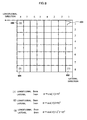
- Fig. 8 is a conceptual diagram showing an example of the operation of the detecting means 113C of the tissue displacement direction shown in Fig. 2. The abscissa in Fig. 8 denotes the coordinate of the subject substantially in parallel with the ultrasound transmitting and receiving
surface 201a, and the ordinate denotes the coordinate of the subject substantially in the vertical direction of the ultrasound transmitting and receivingsurface 201a. The units of the abscissa and the ordinate are millimeter (mm). - Referring to Fig. 8, the detecting means 113C of the tissue displacement direction executes the correlation calculation of the tomographic images after/before applying pressure to the tissue within a wide range on the basis of signals corresponding to pixels. Specifically, the detecting means 113C obtains a
signal 601 before applying pressure to the tissue. Herein, thesignal 601 is at the position of 1 [mm] in the longitudinal direction and of 1 [mm] in the lateral direction. Further, the detecting means 113C detects the moving destination of thesignal 601 upon applying the pressure to the tissue with the correlation processing, and determines the tissue displacement direction on the basis of the detection result. - For example, upon detecting the moving destination of the
signal 601 as the position of a signal 602 (8 [mm] in the longitudinal direction and 1 [mm] in the lateral direction), upon detecting the moving destination of thesignal 601 at the position of thesignal 602, the detecting means 113C determines that the tissue displacement direction is in the longitudinal direction (e.g., 0 degree). Further, upon detecting the moving destination of thesignal 601 at the position of a signal 603 (1 [mm] in the longitudinal direction and 8 [mm] in the lateral direction), the detecting means 113C determines that the tissue displacement direction is in the lateral direction (e.g., 90 degrees). Furthermore, upon detecting the moving destination of thesignal 601 at the position of a signal 604 (8 [mm] in the long-side direction and 8 [mm] in the lateral direction), the detecting means 113C determines that the tissue displacement direction is in the oblique direction (e.g., 45 degrees). The detecting means 113C executes detecting processing of the tissue displacement direction every coordinate and detects an average of the detection values of the coordinates as the tissue displacement direction. The tissue displacement direction is output to the setting means 113B of the displacement search direction and the angle correcting means 113E of the region of interest. Incidentally, processing for measuring the displacement of the tissue so that the displacement search direction matches the tissue displacement direction is similar to that according to the first embodiment. - That is, upon imaging the elasticity image of the thyroid, even if pressure is applied to the tissue such as the thyroid, the tissue can be displaced in the lateral direction. Then, the tissue displacement direction cannot be grasped. On the other hand, according to the third embodiment, since the tissue displacement direction is automatically, objectively, and quantitatively detected, the measurement precision of the displacement of the tissue can be improved.
- The fourth embodiment is different from the third embodiment in that the direction of the blood vessel is used upon automatically detecting the tissue displacement direction. Therefore, different points will be mainly described.
- An ultrasound diagnostic apparatus according to the fourth embodiment has a Doppler
image reconstructing unit 900, as shown in Fig. 1. TheDoppler reconstructing unit 900 calculates the Doppler deviation on the basis of received signals on time series, captured from the ultrasound transmitting and receivingunit 103, and constructures a Doppler image (e.g., color blood flow image) from the Doppler deviation. Further, the setting means 113B of the displacement search direction according to the fourth embodiment determines the displacement search direction that matches the tissue displacement direction, on the basis of the direction of blood flow that can be determined by the Dopplerimage reconstructing unit 900. - Fig. 9 is a diagram for illustrating the operation of the setting means 113B of the displacement search direction according to the fourth embodiment. First, Fig. 9A is a diagram showing a color blood flow image that is superimposed to the
vascular vessel 204 shown in Fig. 3 and the resultant image is displayed. Herein, the color blood flow image is output to theimage display 112 via theimage combining unit 111 from the Dopplerimage reconstructing unit 900. - Fig. 9B is a schematic diagram showing an example for setting the displacement search direction to match the tissue displacement direction on the basis of the blood vessel direction. The detecting means 113C of tissue displacement direction detects the direction of blood flow on the basis of the color blood vessel image shown in Fig. 9A, and determines the direction orthogonal to the direction of blood flow as the tissue displacement direction. The setting means 113B of the displacement search direction determines the displacement search direction to match the tissue displacement direction determined by the detecting means 113C. Incidentally, the setting processing or rotating and correcting processing of the region of
interest 303 and the processing for deflecting the ultrasound beam direction in accordance with the displacement search direction are similar to those according to the first embodiment. As described according to the second embodiment, processing for the displacement search direction of the region ofinterest 303 to match the tissue displacement direction may be applied. - According to the fourth embodiment, since the tissue displacement direction is automatically determined on the basis of the direction of blood flow that can be detected from the Doppler blood flow image, operation for matching the tissue displacement direction to the displacement search direction becomes easy. For example, even if the subject 101 has the blood vessel that is bent, the displacement search direction can be easily determined on the basis of the Doppler blood flow image of the blood vessel.
- The fifth embodiment is different from the first embodiment having the structure for deflecting the ultrasound beams received/sent by the
probe 102 in that the inclination of theprobe 102 is manually adjusted upon matching the displacement search direction to the tissue displacement direction. Therefore, different points will be mainly described. - The inclination of the
probe 102 is changed, thereby changing the inclination angle of the ultrasound transmitting and receivingsurface 201a of theprobe 102. Therefore, it is possible to adjust the direction of the ultrasound beams received/sent by the ultrasound transmitting and receivingsurface 201a. That is, upon the displacement search direction as the direction of the ultrasound beams, the inclination of theprobe 102 is adjusted, thereby matching the displacement search direction to the tissue displacement direction. - However, the inclination of the
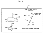
probe 102 is adjusted on the basis of the experience and instinct and operation for matching the displacement search direction to the tissue displacement direction is thus complicated. Then, the guideinformation creating means 113F shown in Fig. 2 creates guide information indicating the inclination direction and the inclination angle of theprobe 102 when the displacement search direction matches the tissue displacement direction and allows theimage display 112 to display the created information. - Fig. 10 is a display example of the guide information indicating the inclination direction and the inclination angle of the
probe 102. Incidentally, a positional sensor for detecting the position and the inclination of theprobe 102 in real time is arranged. Referring to Fig. 10, the guideinformation creating means 113F creates and displays amodel image 920 of theprobe 102 that comes into contact with the body surface of the subject 101, anarrow image 921 indicating the displacement search direction set to match the ultrasound beam direction of theprobe 102, anarrow image 922 indicating the tissue displacement direction of the tissue of the subject 101, and aguide image 923 indicating the inclination direction of theprobe 102 indicating the inclination direction when the displacement search direction matches the tissue displacement direction. Further, the guide information creating means 113F mayangle information 924 indicating a correction angle θ corresponding to the deviation between the displacement search direction and the tissue displacement direction. Herein, the correction angle θ is guide information indicating the inclination angle of theprobe 102. - According to the fifth embodiment, the guide information such as the
guide image 923 andangle information 924 becomes an objective and quantitative index for supporting the operation for matching the displacement search direction to the tissue displacement direction by adjusting the inclination of theprobe 102. Therefore, the operator can visually grasp an inclination direction of the target of theprobe 102, thereby precisely and simply performing the operation for matching the displacement search direction to the tissue displacement direction. As a consequence, the measurement precision of the displacement of the tissue is improved and the convenience of the apparatus can be improved. - Referring to Fig. 11, the guide information creating means 113F may align and display, on the region of
interest 925,angle information 926 indicating an angle θ1 formed between the displacement search direction and the vertical direction (e.g., depth direction of the subject 101), andangle information 927 indicating an angle θ2 formed between the displacement search direction and the tissue displacement direction. As a consequence, the operator can relatively and visually grasp the displacement search direction and the tissue displacement direction of the region ofinterest 925 of the subject 101. - As mentioned above, according to the embodiments, irrespectively of the direction for pressurizing the tissue and the shape of a surface for pressurizing the tissue, it is possible to easily obtain the elasticity image with high quality, precisely indicating the characteristics such as the strain and hardness of the tissue.
- As shown in Figs. 1 and 2, the control functions necessary for ultrasonogram imaging according to the embodiments are described on the unit basis of block. The control functions can be collected as an ultrasonogram imaging program and the ultrasonogram imaging program can be executed by a control computer. For example, the ultrasonogram imaging program enables a control computer to execute: a setting sequence of setting a displacement search direction to match the tissue displacement direction of the tissue of the subject 101; a sequence of supplying a transmitting drive signal to the
probe 102 that receives and transmits ultrasound waves to/from the subject 101; a sequence of processing a received signal output from theprobe 102; a sequence of measuring the displacement of the search direction from signals after the receiving processing; a sequence of reconstructing the elasticity image on the basis of the measurement value of the displacement; and a sequence of displaying the elasticity image. - As mentioned above, the ultrasound diagnostic apparatus according to the embodiments of the present invention is described. The ultrasound diagnostic apparatus according to the present invention can be variously embodied without departing the essentials and main features of the present invention. Therefore, the embodiment is an example and is not limited to this. That is, the range of the present invention includes the modification and change of the equivalent range.
Claims (25)
- An ultrasound diagnostic apparatus comprising:an ultrasound probe for transmitting and receiving ultrasound waves to/from a subject; transmitting means for suppling a drive signal to the ultrasound probe transmitting ultrasound waves to the subject; receiving means for receiving and processing a received signal output from the ultrasound probe; reconstructing means for reconstructing an elasticity-image on the basis of displacement of a tissue measured from an output signal from the receiving means; and displaying means for displaying the elasticity image; wherein further comprising;displacement search direction setting means for setting a displacement search direction to match a tissue displacement direction of the displacement of the tissue;
wherein
the reconstructing means measures the displacement of the search direction and reconstructs the elasticity image. - The ultrasound diagnostic apparatus according to Claim 1, wherein
the displacement search direction setting means outputs a command for deflecting the ultrasound beam to match the tissue displacement direction to the transmitting means or the receiving means, upon setting the search direction to a direction of ultrasound beams of the ultrasound probe. - The ultrasound diagnostic apparatus according to Claim 1, further comprising:region setting means for setting a region of interest predetermined the displacement search direction corresponding to the tissue of the subject; and correcting means for correcting a rotation angle of the region of interest so that the search direction matches to the tissue displacement direction, whereinthe displacement search direction setting means outputs, to the transmitting means or the receiving means, a command for deflecting the ultrasound beam to match the search direction of the region of interest after the rotation and correction.
- The ultrasound diagnostic apparatus according to Claim 3, wherein
the region setting means sets a rectangular- or fan-shaped region of interest corresponding to the tissue of the subject. - The ultrasound diagnostic apparatus according to Claim 1, wherein
the displacement search direction setting means outputs, to the elasticity-image reconstructing means, a command for selecting signals aligned in the search direction and a command for calculating the displacement of the search direction on the basis of the selected signals, from among signals output from the receiving means. - The ultrasound diagnostic apparatus according to Claim 1, further comprising:region setting means for setting a region of interest predetermined the displacement search direction corresponding to the tissue of the subject; and correcting means for correcting a rotation angle of the region of interest so that the search direction matches to the tissue displacement direction, whereinthe displacement search direction setting means outputs, to the elasticity-image reconstructing means, a command for selecting signals aligned corresponding to the search direction of the region of interest from among signals output from the receiving means and corrected by the correcting means, and a command for calculating the displacement of the search direction on the basis of the selected signals.
- The ultrasound diagnostic apparatus according to Claim 6, wherein
the region setting means sets a rectangular- or fan-shaped region of interest corresponding to the tissue of the subject. - The ultrasound diagnostic apparatus according to Claim 1, wherein
the displacement search direction setting means divides the region of interest set to the tissue into a plurality of minute rectangular regions of interest, specifies the tissue displacement direction of the minute rectangular regions of interest, and sets the search direction to match the tissue displacement direction. - The ultrasound diagnostic apparatus according to Claim 1, further comprising:a tissue displacement direction detecting means for detecting the tissue displacement direction, whereinthe tissue displacement direction detecting means determines, as the tissue displacement direction, a direction orthogonal to a line segment between two reference points determined on a tomographic image of the tissue.
- The ultrasound diagnostic apparatus according to Claim 1, further comprising:a tissue displacement direction detecting means for detecting the tissue displacement direction, whereinthe tissue displacement direction detecting means executes correlation process of a tomographic image before applying pressure to a tissue and a tomographic image during applying pressure to the tissue, obtains a moving direction of a portion on the tomographic image, and determines the moving direction as the tissue displacement direction.
- The ultrasound diagnostic apparatus according to Claim 1, further comprising;
a tissue displacement direction detecting means for detecting a tissue displacement direction, wherein
the tissue displacement direction detecting means obtains a direction of blood flow from the output signal from the receiving means with Doppler calculating processing, and determines a direction orthogonal to the direction of blood flow as the tissue displacement direction. - The ultrasound diagnostic apparatus according to Claim 1, wherein
the displaying means displays guide information indicating an inclination direction or an inclination angle of the ultrasound probe when the direction of the ultrasound beams matches the tissue displacement direction, upon setting the search direction to the direction of ultrasound beam of the ultrasound probe. - The ultrasound diagnostic apparatus according to Claim 1, wherein
the displaying means displays at least one of an arrow image indicating the tissue displacement direction, an arrow image indicating the displacement search direction, and an arrow image of the ultrasound probe in the direction of the ultrasound beam. - The ultrasound diagnostic apparatus according to Claim 1, wherein
the displaying means displays an angle formed between the tissue displacement direction and the displacement search direction. - A program for enabling a control computer to take an ultrasonogram comprising:a setting process of a displacement search direction to match a tissue displacement direction for displacing the tissue of a subject;a supplying process for supplying a drive signal to the ultrasound probe that transmits the ultrasound waves to the subject;a receiving process for receiving and processing a signal output from the ultrasound probe;a measuring process for measuring a displacement of the search direction from the receieved signal processed by the receiving procedure;a reconstructing process for reconstructing an elasticity image on the basis of the measurement value of the displacement; anda displaying process for displaying the elasticity image.
- A method for imaging an ultrasonogram comprising:a setting step of setting a displacement search direction to match a tissue displacement direction for displacing the tissue of a subject;a transmitting step for supplying a drive signal to an ultrasound probe that transmits and receives ultrasound waves to/from the subject;a receiving step for receiveing and processing a signal output from the ultrasound probe;a measuring step for measuring the displacement of the search direction from a signal after the receiving processing;a reconstructing step for reconstructing an elasticity image on the basis of the measurement value of the displacement; anda displaying step for displaying the elasticity image.
- A method for imaging an ultrasonogram according to Claim 16, wherein
the setting step comprises a step of deflecting the ultrasound beam to match the tissue displacement direction, upon setting the search direction to an ultrasound beam direction of the ultrasound probe. - A method for imaging an ultrasonogram according to Claim 16, wherein
the setting step of the displacement search direction comprises: a step of selecting signals aligned corresponding to the search direction from among signal output from the receiving means; and
a step of calculating the displacement of the search direction on the basis of the selected signal. - A method for imaging an ultrasonogram according to Claim 16, wherein
the setting step of the displacement search direction comprises:a step of dividing the region of interest set to the tissue into a plurality of fine and rectangular regions of interest, specifying the tissue displacement direction of the fine and rectangular region of interest, and setting the search direction to match the tissue displacement direction. - A method for imaging an ultrasonogram according to Claim 16, further comprising:a detecting step of the tissue displacement direction of detecting the tissue displacement direction, upon setting the displacement search direction to match the tissue displacement direction,wherein the detecting step of the tissue displacement direction comprises a step of determining, as the tissue displacement direction, a direction orthogonal to a line segment between two reference points determined on a tomographic image of the tissue.
- A method for imaging an ultrasonogram according to Claim 16, further comprising:a detecting step of the tissue displacement direction of detecting the tissue displacement direction upon setting the displacement search direction to match the tissue displacement direction,wherein the detecting step of the tissue displacement direction comprises a step of executing correlation processing of a tomographic image before applying pressure to the tissue and a tomographic image during applying pressure to the tissue, obtaining a moving direction of a portion on the tomographic image, and determining the moving direction as the tissue displacement direction.
- A method for imaging an ultrasonogram according to Claim 16, further comprising:a detecting step of a tissue displacement direction of detecting the tissue displacement direction, upon setting the displacement search direction to match the tissue displacement direction,wherein the detecting step of the tissue displacement direction comprises a step of allowing a direction of blood flow to be obtained from the output signal from the receiving means with Doppler calculating processing, and determining a direction orthogonal to the direction of blood flow as the tissue displacement direction.
- A method for imaging an ultrasonogram according to Claim 16, wherein
the display step comprises a step of displaying guide information indicating an inclination direction or an inclination angle of the ultrasound probe when the direction of the ultrasound beams matches the tissue displacement direction, upon setting the search direction to the direction of ultrasound beam of the ultrasound probe. - A method for imaging an ultrasonogram according to Claim 16, wherein
the display step includes a step of displaying at least one of an arrow image indicating the tissue displacement direction, an arrow image indicating the displacement search direction, and an arrow image of the ultrasound probe in the direction of the ultrasound beam. - A method for imaging an ultrasonogram according to Claim 16, wherein
the displaying step comprises a step of displaying an angle formed between the tissue displacement direction and the displacement search direction.
Applications Claiming Priority (2)
| Application Number | Priority Date | Filing Date | Title |
|---|---|---|---|
| JP2005000257 | 2005-01-04 | ||
| PCT/JP2005/023886 WO2006073088A1 (en) | 2005-01-04 | 2005-12-27 | Ultrasonographic device, ultrasonographic program, and ultrasonographic method |
Publications (3)
| Publication Number | Publication Date |
|---|---|
| EP1834588A1 true EP1834588A1 (en) | 2007-09-19 |
| EP1834588A4 EP1834588A4 (en) | 2009-03-11 |
| EP1834588B1 EP1834588B1 (en) | 2011-07-13 |
Family
ID=36647570
Family Applications (1)
| Application Number | Title | Priority Date | Filing Date |
|---|---|---|---|
| EP05822712A Not-in-force EP1834588B1 (en) | 2005-01-04 | 2005-12-27 | Ultrasonographic device, ultrasonographic program, and ultrasonographic method |
Country Status (5)
| Country | Link |
|---|---|
| US (1) | US7766836B2 (en) |
| EP (1) | EP1834588B1 (en) |
| JP (2) | JPWO2006073088A1 (en) |
| CN (1) | CN101094611B (en) |
| WO (1) | WO2006073088A1 (en) |
Cited By (9)
| Publication number | Priority date | Publication date | Assignee | Title |
|---|---|---|---|---|
| EP2506762A1 (en) * | 2009-12-01 | 2012-10-10 | Kyma Medical Technologies Ltd | Locating features in the heart using radio frequency imaging |
| EP2476376A4 (en) * | 2009-09-10 | 2016-03-30 | Hitachi Medical Corp | Ultrasonic diagnostic device and elasticity image display method |
| US9788752B2 (en) | 2010-07-21 | 2017-10-17 | Zoll Medical Israel Ltd. | Implantable dielectrometer |
| US10548485B2 (en) | 2015-01-12 | 2020-02-04 | Zoll Medical Israel Ltd. | Systems, apparatuses and methods for radio frequency-based attachment sensing |
| US10588599B2 (en) | 2008-05-27 | 2020-03-17 | Zoll Medical Israel Ltd. | Methods and systems for determining fluid content of tissue |
| US10680324B2 (en) | 2013-10-29 | 2020-06-09 | Zoll Medical Israel Ltd. | Antenna systems and devices and methods of manufacture thereof |
| US11013420B2 (en) | 2014-02-05 | 2021-05-25 | Zoll Medical Israel Ltd. | Systems, apparatuses and methods for determining blood pressure |
| US11020002B2 (en) | 2017-08-10 | 2021-06-01 | Zoll Medical Israel Ltd. | Systems, devices and methods for physiological monitoring of patients |
| US11259715B2 (en) | 2014-09-08 | 2022-03-01 | Zoll Medical Israel Ltd. | Monitoring and diagnostics systems and methods |
Families Citing this family (46)
| Publication number | Priority date | Publication date | Assignee | Title |
|---|---|---|---|---|
| JP5490979B2 (en) * | 2006-05-25 | 2014-05-14 | 株式会社日立メディコ | Ultrasonic diagnostic equipment |
| FR2913875B1 (en) * | 2007-03-21 | 2009-08-07 | Echosens Sa | DEVICE FOR MEASURING VISCOELASTIC PROPERTIES OF BIOLOGICAL TISSUES AND METHOD USING THE DEVICE |
| JP4889540B2 (en) * | 2007-03-28 | 2012-03-07 | 株式会社日立メディコ | Ultrasonic diagnostic equipment |
| JP5127371B2 (en) * | 2007-08-31 | 2013-01-23 | キヤノン株式会社 | Ultrasound image diagnostic system and control method thereof |
| EP2189118A4 (en) * | 2007-09-06 | 2013-10-23 | Hitachi Medical Corp | Ultrasonograph |
| WO2009063691A1 (en) * | 2007-11-16 | 2009-05-22 | Hitachi Medical Corporation | Ultrasonic imaging system |
| US20090203997A1 (en) * | 2008-02-07 | 2009-08-13 | Kutay Ustuner | Ultrasound displacement imaging with spatial compounding |
| US8403850B2 (en) * | 2008-03-25 | 2013-03-26 | Wisconsin Alumni Research Foundation | Rapid two/three-dimensional sector strain imaging |
| JP5249327B2 (en) * | 2008-07-01 | 2013-07-31 | パナソニック株式会社 | Ultrasonic diagnostic equipment |
| US8172753B2 (en) * | 2008-07-11 | 2012-05-08 | General Electric Company | Systems and methods for visualization of an ultrasound probe relative to an object |
| WO2010024168A1 (en) * | 2008-08-29 | 2010-03-04 | 株式会社 日立メディコ | Ultrasonic diagnosing device |
| US8696573B2 (en) * | 2008-11-10 | 2014-04-15 | Canon Kabushiki Kaisha | Ultrasonographic diagnostic system and ultrasonic diagnostic device |
| JP2010124946A (en) * | 2008-11-26 | 2010-06-10 | Ge Medical Systems Global Technology Co Llc | Ultrasonic diagnosing apparatus, and program |
| WO2010098233A1 (en) * | 2009-02-24 | 2010-09-02 | 株式会社 日立メディコ | Ultrasonic diagnostic device and elasticity image display method |
| KR101107392B1 (en) * | 2009-04-10 | 2012-01-19 | 삼성메디슨 주식회사 | Ultrasound system and method of providing guide information |
| JP5356140B2 (en) * | 2009-07-22 | 2013-12-04 | ジーイー・メディカル・システムズ・グローバル・テクノロジー・カンパニー・エルエルシー | Ultrasonic diagnostic apparatus and control program therefor |
| JP5665040B2 (en) * | 2009-09-10 | 2015-02-04 | 学校法人上智学院 | Displacement measuring method and apparatus, and ultrasonic diagnostic apparatus |
| US20120203108A1 (en) * | 2009-10-28 | 2012-08-09 | Hitachi Medical Corporation | Ultrasonic diagnostic apparatus and image construction method |
| JP5509437B2 (en) * | 2010-03-01 | 2014-06-04 | 国立大学法人山口大学 | Ultrasonic diagnostic equipment |
| US20120330158A1 (en) * | 2010-03-19 | 2012-12-27 | Hitachi Medical Corporation | Ultrasonic diagnostic apparatus and ultrasonic image display method |
| US20130072794A1 (en) * | 2010-06-04 | 2013-03-21 | Hitachi Medical Corporation | Ultrasonic diagnostic apparatus and ultrasonic transmission/reception method |
| TWI444210B (en) * | 2010-06-09 | 2014-07-11 | Univ Chang Gung | The ultrasonic system having the real-time monitored apparatus |
| JP5528935B2 (en) * | 2010-07-28 | 2014-06-25 | 日立アロカメディカル株式会社 | Ultrasonic diagnostic equipment |
| CN103108593B (en) * | 2010-09-21 | 2015-11-25 | 株式会社日立医疗器械 | The display packing of diagnostic ultrasound equipment and ultrasonography |
| JP5209026B2 (en) * | 2010-10-27 | 2013-06-12 | ジーイー・メディカル・システムズ・グローバル・テクノロジー・カンパニー・エルエルシー | Ultrasonic diagnostic equipment |
| JP5501999B2 (en) * | 2011-03-08 | 2014-05-28 | 富士フイルム株式会社 | Ultrasonic diagnostic apparatus and elasticity index reliability determination method |
| US20120259224A1 (en) * | 2011-04-08 | 2012-10-11 | Mon-Ju Wu | Ultrasound Machine for Improved Longitudinal Tissue Analysis |
| CN102423264B (en) * | 2011-09-01 | 2014-05-21 | 中国科学院深圳先进技术研究院 | Image-based biological tissue elasticity measuring method and device |
| KR101495526B1 (en) | 2011-12-29 | 2015-02-26 | 삼성메디슨 주식회사 | Method and apparatus for providing acoustic radiation force impulse imaging |
| WO2013116783A1 (en) | 2012-02-03 | 2013-08-08 | Los Alamos National Security, Llc | Windowed time-reversal music technique for super-resolution ultrasound imaging |
| WO2013116809A1 (en) | 2012-02-03 | 2013-08-08 | Los Alamos National Security, Llc | Ultrasound waveform tomography with tv regularization |
| JP6063454B2 (en) * | 2012-04-13 | 2017-01-18 | 株式会社日立製作所 | Ultrasonic diagnostic apparatus and locus display method |
| KR101501519B1 (en) | 2012-09-18 | 2015-03-18 | 삼성메디슨 주식회사 | Method and apparatus for guiding scan line using color doppler images |
| JP6084424B2 (en) * | 2012-10-04 | 2017-02-22 | 東芝メディカルシステムズ株式会社 | Ultrasonic diagnostic equipment |
| WO2014058238A1 (en) * | 2012-10-12 | 2014-04-17 | 삼성메디슨 주식회사 | Method for displaying ultrasonic image and ultrasonic medical device using doppler data |
| KR102070262B1 (en) * | 2012-11-29 | 2020-03-02 | 삼성전자주식회사 | Ultrasonic Probe apparatus and Method for controlling Ultrasonic Probe apparatus thereof |
| JP5908852B2 (en) | 2013-02-06 | 2016-04-26 | ジーイー・メディカル・システムズ・グローバル・テクノロジー・カンパニー・エルエルシー | Ultrasonic diagnostic apparatus and control program therefor |
| JP2014176544A (en) * | 2013-03-15 | 2014-09-25 | Seiko Epson Corp | Ultrasonic measuring device and ultrasonic imaging device |
| KR101512291B1 (en) | 2013-05-06 | 2015-04-15 | 삼성메디슨 주식회사 | Medical imaging apparatus and method of providing medical images |
| JP6333608B2 (en) * | 2014-04-16 | 2018-05-30 | キヤノンメディカルシステムズ株式会社 | Ultrasonic diagnostic apparatus and control program |
| JP6246098B2 (en) * | 2014-08-27 | 2017-12-13 | ジーイー・メディカル・システムズ・グローバル・テクノロジー・カンパニー・エルエルシー | Ultrasonic diagnostic apparatus and control program therefor |
| US10646201B2 (en) | 2014-11-18 | 2020-05-12 | C. R. Bard, Inc. | Ultrasound imaging system having automatic image presentation |
| EP3220828B1 (en) | 2014-11-18 | 2021-12-22 | C.R. Bard, Inc. | Ultrasound imaging system having automatic image presentation |
| JP7334486B2 (en) * | 2019-06-07 | 2023-08-29 | コニカミノルタ株式会社 | ULTRASOUND DIAGNOSTIC APPARATUS, ULTRASOUND DIAGNOSTIC SYSTEM CONTROL METHOD, AND ULTRASOUND DIAGNOSTIC SYSTEM CONTROL PROGRAM |
| FR3104736B1 (en) | 2019-12-13 | 2022-12-09 | Supersonic Imagine | Ultrasonic method for quantifying the nonlinear elasticity by shear waves of a medium, and device for carrying out this method |
| US11810224B2 (en) * | 2021-02-18 | 2023-11-07 | GE Precision Healthcare LLC | Method and system for transposing markers added to a first ultrasound imaging mode dataset to a second ultrasound imaging mode dataset |
Citations (5)
| Publication number | Priority date | Publication date | Assignee | Title |
|---|---|---|---|---|
| US5495771A (en) * | 1993-08-12 | 1996-03-05 | Kiyoshi Nakayama | Elasticity measuring method and elasticity measuring apparatus |
| EP0842638A2 (en) * | 1996-11-08 | 1998-05-20 | ATL Ultrasound, Inc. | Ultrasonic diagnostic imaging system with real time volume flow calculation |
| US6048317A (en) * | 1998-09-18 | 2000-04-11 | Hewlett-Packard Company | Method and apparatus for assisting a user in positioning an ultrasonic transducer |
| EP1123687A2 (en) * | 2000-02-10 | 2001-08-16 | Aloka Co., Ltd. | Ultrasonic diagnostic apparatus |
| US20040034304A1 (en) * | 2001-12-21 | 2004-02-19 | Chikayoshi Sumi | Displacement measurement method and apparatus, strain measurement method and apparatus elasticity and visco-elasticity constants measurement apparatus, and the elasticity and visco-elasticity constants measurement apparatus-based treatment apparatus |
Family Cites Families (7)
| Publication number | Priority date | Publication date | Assignee | Title |
|---|---|---|---|---|
| JP3195056B2 (en) * | 1992-07-15 | 2001-08-06 | フクダ電子株式会社 | Ultrasound diagnostic equipment |
| JP4201396B2 (en) | 1998-08-20 | 2008-12-24 | 株式会社日立メディコ | Ultrasonic diagnostic equipment |
| JP2000271117A (en) * | 1999-03-25 | 2000-10-03 | Aloka Co Ltd | Ultrasonic blood vessel measuring device |
| JP3464185B2 (en) * | 2000-02-10 | 2003-11-05 | アロカ株式会社 | Ultrasound diagnostic equipment |
| JP4768100B2 (en) * | 2000-04-25 | 2011-09-07 | 日立アロカメディカル株式会社 | Ultrasonic diagnostic equipment |
| US6508768B1 (en) * | 2000-11-22 | 2003-01-21 | University Of Kansas Medical Center | Ultrasonic elasticity imaging |
| JP3932485B2 (en) * | 2003-05-30 | 2007-06-20 | 株式会社日立メディコ | Ultrasonic diagnostic equipment |
-
2005
- 2005-12-27 CN CN2005800458659A patent/CN101094611B/en not_active Expired - Fee Related
- 2005-12-27 EP EP05822712A patent/EP1834588B1/en not_active Not-in-force
- 2005-12-27 WO PCT/JP2005/023886 patent/WO2006073088A1/en active Application Filing
- 2005-12-27 US US11/813,291 patent/US7766836B2/en not_active Expired - Fee Related
- 2005-12-27 JP JP2006550791A patent/JPWO2006073088A1/en active Pending
-
2012
- 2012-10-05 JP JP2012223371A patent/JP5496302B2/en not_active Expired - Fee Related
Patent Citations (5)
| Publication number | Priority date | Publication date | Assignee | Title |
|---|---|---|---|---|
| US5495771A (en) * | 1993-08-12 | 1996-03-05 | Kiyoshi Nakayama | Elasticity measuring method and elasticity measuring apparatus |
| EP0842638A2 (en) * | 1996-11-08 | 1998-05-20 | ATL Ultrasound, Inc. | Ultrasonic diagnostic imaging system with real time volume flow calculation |
| US6048317A (en) * | 1998-09-18 | 2000-04-11 | Hewlett-Packard Company | Method and apparatus for assisting a user in positioning an ultrasonic transducer |
| EP1123687A2 (en) * | 2000-02-10 | 2001-08-16 | Aloka Co., Ltd. | Ultrasonic diagnostic apparatus |
| US20040034304A1 (en) * | 2001-12-21 | 2004-02-19 | Chikayoshi Sumi | Displacement measurement method and apparatus, strain measurement method and apparatus elasticity and visco-elasticity constants measurement apparatus, and the elasticity and visco-elasticity constants measurement apparatus-based treatment apparatus |
Non-Patent Citations (1)
| Title |
|---|
| See also references of WO2006073088A1 * |
Cited By (19)
| Publication number | Priority date | Publication date | Assignee | Title |
|---|---|---|---|---|
| US10588599B2 (en) | 2008-05-27 | 2020-03-17 | Zoll Medical Israel Ltd. | Methods and systems for determining fluid content of tissue |
| US9265438B2 (en) | 2008-05-27 | 2016-02-23 | Kyma Medical Technologies Ltd. | Locating features in the heart using radio frequency imaging |
| EP2476376A4 (en) * | 2009-09-10 | 2016-03-30 | Hitachi Medical Corp | Ultrasonic diagnostic device and elasticity image display method |
| EP2506762A4 (en) * | 2009-12-01 | 2013-07-24 | Kyma Medical Technologies Ltd | Locating features in the heart using radio frequency imaging |
| EP2506762A1 (en) * | 2009-12-01 | 2012-10-10 | Kyma Medical Technologies Ltd | Locating features in the heart using radio frequency imaging |
| US11471127B2 (en) | 2009-12-01 | 2022-10-18 | Zoll Medical Israel Ltd. | Methods and systems for determining fluid content of tissue |
| US10660609B2 (en) | 2009-12-01 | 2020-05-26 | Zoll Medical Israel Ltd. | Methods and systems for determining fluid content of tissue |
| US9788752B2 (en) | 2010-07-21 | 2017-10-17 | Zoll Medical Israel Ltd. | Implantable dielectrometer |
| US10136833B2 (en) | 2010-07-21 | 2018-11-27 | Zoll Medical Israel, Ltd. | Implantable radio-frequency sensor |
| US10680324B2 (en) | 2013-10-29 | 2020-06-09 | Zoll Medical Israel Ltd. | Antenna systems and devices and methods of manufacture thereof |
| US11108153B2 (en) | 2013-10-29 | 2021-08-31 | Zoll Medical Israel Ltd. | Antenna systems and devices and methods of manufacture thereof |
| US11539125B2 (en) | 2013-10-29 | 2022-12-27 | Zoll Medical Israel Ltd. | Antenna systems and devices, and methods of manufacture thereof |
| US11013420B2 (en) | 2014-02-05 | 2021-05-25 | Zoll Medical Israel Ltd. | Systems, apparatuses and methods for determining blood pressure |
| US11883136B2 (en) | 2014-02-05 | 2024-01-30 | Zoll Medical Israel Ltd. | Systems, apparatuses and methods for determining blood pressure |
| US11259715B2 (en) | 2014-09-08 | 2022-03-01 | Zoll Medical Israel Ltd. | Monitoring and diagnostics systems and methods |
| US10548485B2 (en) | 2015-01-12 | 2020-02-04 | Zoll Medical Israel Ltd. | Systems, apparatuses and methods for radio frequency-based attachment sensing |
| US11241158B2 (en) | 2015-01-12 | 2022-02-08 | Zoll Medical Israel Ltd. | Systems, apparatuses and methods for radio frequency-based attachment sensing |
| US11020002B2 (en) | 2017-08-10 | 2021-06-01 | Zoll Medical Israel Ltd. | Systems, devices and methods for physiological monitoring of patients |
| US11872012B2 (en) | 2017-08-10 | 2024-01-16 | Zoll Medical Israel Ltd. | Systems, devices and methods for physiological monitoring of patients |
Also Published As
| Publication number | Publication date |
|---|---|
| US7766836B2 (en) | 2010-08-03 |
| EP1834588B1 (en) | 2011-07-13 |
| JP5496302B2 (en) | 2014-05-21 |
| JP2013034883A (en) | 2013-02-21 |
| EP1834588A4 (en) | 2009-03-11 |
| WO2006073088A1 (en) | 2006-07-13 |
| CN101094611A (en) | 2007-12-26 |
| JPWO2006073088A1 (en) | 2008-06-12 |
| US20080081993A1 (en) | 2008-04-03 |
| CN101094611B (en) | 2010-08-18 |
Similar Documents
| Publication | Publication Date | Title |
|---|---|---|
| EP1834588B1 (en) | Ultrasonographic device, ultrasonographic program, and ultrasonographic method | |
| EP1800603B1 (en) | Method and apparatus for displaying elastic image and ultrasonograph | |
| US20120123263A1 (en) | Ultrasonic diagnostic apparatus and ultrasonic measurement method | |
| US6558324B1 (en) | System and method for strain image display | |
| US8491475B2 (en) | Ultrasonic diagnostic apparatus, ultrasonic diagnostic method, and imaging processing program for ultrasonic diagnostic apparatus | |
| JP4898809B2 (en) | Ultrasonic diagnostic equipment | |
| US8382669B2 (en) | Ultrasonic diagnostic apparatus and ultrasonic diagnostic apparatus control method | |
| JP4314035B2 (en) | Ultrasonic diagnostic equipment | |
| US7766832B2 (en) | Ultrasonic diagnostic device and image processing device | |
| JP5436533B2 (en) | Ultrasonic diagnostic apparatus and elastic image display method | |
| JP4903271B2 (en) | Ultrasound imaging system | |
| JP5411699B2 (en) | Ultrasonic imaging device | |
| WO2006022238A1 (en) | Ultrasonographic device | |
| US20150094580A1 (en) | Ultrasonic diagnostic device and locus display method | |
| JP3645347B2 (en) | Ultrasonic diagnostic apparatus and delay time optimization method | |
| JP4889540B2 (en) | Ultrasonic diagnostic equipment | |
| JP4368185B2 (en) | Ultrasonic diagnostic equipment | |
| JP4601413B2 (en) | Ultrasonic diagnostic equipment | |
| US20140180090A1 (en) | Ultrasound diagnostic apparatus, tissue elasticity measurement method, and recording medium | |
| JP2007159945A (en) | Ultrasonic diagnostic apparatus |
Legal Events
| Date | Code | Title | Description |
|---|---|---|---|
| PUAI | Public reference made under article 153(3) epc to a published international application that has entered the european phase |
Free format text: ORIGINAL CODE: 0009012 |
|
| 17P | Request for examination filed |
Effective date: 20070731 |
|
| AK | Designated contracting states |
Kind code of ref document: A1 Designated state(s): DE FR GB IT NL |
|
| RBV | Designated contracting states (corrected) |
Designated state(s): DE FR GB IT NL |
|
| DAX | Request for extension of the european patent (deleted) | ||
| A4 | Supplementary search report drawn up and despatched |
Effective date: 20090209 |
|
| 17Q | First examination report despatched |
Effective date: 20090716 |
|
| GRAP | Despatch of communication of intention to grant a patent |
Free format text: ORIGINAL CODE: EPIDOSNIGR1 |
|
| GRAS | Grant fee paid |
Free format text: ORIGINAL CODE: EPIDOSNIGR3 |
|
| RAP1 | Party data changed (applicant data changed or rights of an application transferred) |
Owner name: HITACHI MEDICAL CORPORATION |
|
| GRAA | (expected) grant |
Free format text: ORIGINAL CODE: 0009210 |
|
| AK | Designated contracting states |
Kind code of ref document: B1 Designated state(s): DE FR GB IT NL |
|
| REG | Reference to a national code |
Ref country code: GB Ref legal event code: FG4D |
|
| REG | Reference to a national code |
Ref country code: DE Ref legal event code: R096 Ref document number: 602005029024 Country of ref document: DE Effective date: 20110901 |
|
| REG | Reference to a national code |
Ref country code: NL Ref legal event code: VDEP Effective date: 20110713 |
|
| PG25 | Lapsed in a contracting state [announced via postgrant information from national office to epo] |
Ref country code: NL Free format text: LAPSE BECAUSE OF FAILURE TO SUBMIT A TRANSLATION OF THE DESCRIPTION OR TO PAY THE FEE WITHIN THE PRESCRIBED TIME-LIMIT Effective date: 20110713 |
|
| PLBE | No opposition filed within time limit |
Free format text: ORIGINAL CODE: 0009261 |
|
| STAA | Information on the status of an ep patent application or granted ep patent |
Free format text: STATUS: NO OPPOSITION FILED WITHIN TIME LIMIT |
|
| 26N | No opposition filed |
Effective date: 20120416 |
|
| REG | Reference to a national code |
Ref country code: DE Ref legal event code: R097 Ref document number: 602005029024 Country of ref document: DE Effective date: 20120416 |
|
| GBPC | Gb: european patent ceased through non-payment of renewal fee |
Effective date: 20111227 |
|
| PG25 | Lapsed in a contracting state [announced via postgrant information from national office to epo] |
Ref country code: GB Free format text: LAPSE BECAUSE OF NON-PAYMENT OF DUE FEES Effective date: 20111227 |
|
| PGFP | Annual fee paid to national office [announced via postgrant information from national office to epo] |
Ref country code: IT Payment date: 20141218 Year of fee payment: 10 |
|
| REG | Reference to a national code |
Ref country code: FR Ref legal event code: PLFP Year of fee payment: 11 |
|
| PGFP | Annual fee paid to national office [announced via postgrant information from national office to epo] |
Ref country code: FR Payment date: 20151124 Year of fee payment: 11 |
|
| PGFP | Annual fee paid to national office [announced via postgrant information from national office to epo] |
Ref country code: DE Payment date: 20151230 Year of fee payment: 11 |
|
| PG25 | Lapsed in a contracting state [announced via postgrant information from national office to epo] |
Ref country code: IT Free format text: LAPSE BECAUSE OF NON-PAYMENT OF DUE FEES Effective date: 20151227 |
|
| REG | Reference to a national code |
Ref country code: DE Ref legal event code: R119 Ref document number: 602005029024 Country of ref document: DE |
|
| REG | Reference to a national code |
Ref country code: FR Ref legal event code: ST Effective date: 20170831 |
|
| PG25 | Lapsed in a contracting state [announced via postgrant information from national office to epo] |
Ref country code: FR Free format text: LAPSE BECAUSE OF NON-PAYMENT OF DUE FEES Effective date: 20170102 |
|
| PG25 | Lapsed in a contracting state [announced via postgrant information from national office to epo] |
Ref country code: DE Free format text: LAPSE BECAUSE OF NON-PAYMENT OF DUE FEES Effective date: 20170701 |