JP3645347B2 - Ultrasonic diagnostic apparatus and delay time optimization method - Google Patents
Ultrasonic diagnostic apparatus and delay time optimization method Download PDFInfo
- Publication number
- JP3645347B2 JP3645347B2 JP03689696A JP3689696A JP3645347B2 JP 3645347 B2 JP3645347 B2 JP 3645347B2 JP 03689696 A JP03689696 A JP 03689696A JP 3689696 A JP3689696 A JP 3689696A JP 3645347 B2 JP3645347 B2 JP 3645347B2
- Authority
- JP
- Japan
- Prior art keywords
- ultrasonic
- correlation
- delay time
- signal
- scanning
- Prior art date
- Legal status (The legal status is an assumption and is not a legal conclusion. Google has not performed a legal analysis and makes no representation as to the accuracy of the status listed.)
- Expired - Fee Related
Links
Images


Description
【0001】
【発明の属する技術分野】
本発明は、超音波信号を用いて体内の断層像を表示する、いわゆる超音波診断装置及び超音波信号に与える遅延時間を最適化する遅延時間最適化方法に係わり、特に、生体内の音速値の不確定さによって生ずる超音波ビームパターン劣化を自動的に補正し、高分解能化を図った超音波診断装置及び遅延時間最適化方法に関する。
【0002】
【従来の技術】
超音波信号(超音波ビーム、超音波パルスともいう)を被検体の体内に放射し、当該被検体内の各組織からの反射波により生体情報を得る超音波診断法は、超音波断層法と超音波ドップラ法の2つの技術開発により近年急速な進歩を遂げている。今日最も普及している電子走査型の装置は、配列型(アレイ型)の超音波トランスデューサ(超音波振動子)を用い、これを電子的に高速度に制御し走査することによって、リアルタイム表示を可能とした。
【0003】
例えばセクタ電子走査型超音波診断装置の従来例をブロック図を用いて図19に示す。超音波プローブにおいて配列されている振動子の素子数をMとする(振動子4(1)〜4(M))。超音波パルスを生体内(あるいは媒質内)へ送信する場合には、まず送信レート信号発生器1から、超音波パルスの繰り返し周波数を決定するレートパルスが出力される。このレートパルスは、Mチャンネルから構成される送信用遅延回路2(1)〜2(M)に送られ、送信時の超音波ビームの収束距離(F0 )を決定する遅延時間τf と、所定方向(θ0 )に超音波ビームを偏向するための遅延時間τs とが与えられてMチャンネルの振動子駆動回路(パルサ)3(1)〜3(M)に供給される。
【0004】
すなわち、m番目の遅延回路2(m)において設定される遅延時間τ(m)は、τf (m)+τs (m)であり、τf 及びτs は次のように設定される(τf (m)については図3参照)。
【0005】
【数1】

【0006】
このパルサ3(1)〜3(M)では、前記超音波振動子4(1)〜4(M)を駆動し超音波を発生するための駆動パルスが生成され、その駆動パルスの送信タイミングは送信用遅延回路2(1)〜2(M)の出力によって決定される。このパルサ(駆動回路)3(1)〜3(M)の出力は、超音波振動子4(1)〜4(M)に供給され、当該超音波振動子4(1)〜4(M)を駆動し、超音波を発生する。
【0007】
超音波振動子4(1)〜4(M)から発生し、生体内に放射された超音波の一部は、生体内の臓器の境界面あるいは生体組織の音響散乱体にて反射され、再び超音波振動子4(1)〜4(M)によって受信され、電気信号に変換される。この受信信号は、プリアンプ5(1)〜5(M)を介して増幅された後、送信時同様、受信時の超音波ビームの収束距離を決定する遅延時間と超音波ビームの偏向角度を決定するための遅延時間と与えるためのMチャンネルの受信用遅延回路6(1)〜6(M)を経て加算器7に送られる。この加算器7でMチャンネルの受信用遅延回路6の出力信号は加算合成される。そして、その加算器7の出力信号は、対数増幅器8、包絡線検波回路9にて対数圧縮、検波され、A/D変換器10によりA/D変換された後、図示しない書き込み・読み出し制御器により画像メモリ11に一旦ストアされる。
【0008】
画像メモリ11にストアされた信号は、書き込み・読み出し制御器によりテレビフォーマットで読み出されてテレビモニタ13に送られ、そのモニタ13にて超音波断層像として表示される。
【0009】
一方、加算器7の出力は、2つの直交位相検波回路に送られる。すなわち、加算器7の出力は、まずミキサ回路14−1,14−2に送られる。また、基準信号発生器20からは、所定の周波数(一般には超音波周波数f0 に略等しい周波数が用いられる)を有する連続波(基準信号)が出力される。この基準信号発生器20の出力は分岐し、その一方は、移相器15にて位相が90度SHIFTしてミキサ回路14−1に入力され、他方は、直接ミキサ回路14−2に入力される。このミキサ回路14−1,14−2の出力は、ローパスフィルタ16−1,16−2に送られ、そのローパスフィルタ16−1,16−2により和の周波数成分が除去され差の周波数成分のみが抽出される。この差の周波数を有した信号は、A/D変換器17−1,17−2にてディジタル信号に変換された後一旦メモリ回路にストアされる。
【0010】
一方、ドップラ信号を算出するためには、同一部位を連続的に走査し、そのときの複数の信号を用いる必要がある。この複数回走査により得られた複数の信号をメモリ(図示せず)にて一旦記憶し、所定のデータ数が揃った時点でFFT回路18にてドップラ信号の周波数分析が行なわれ、ドップラ周波数(流速)が求められる。FFT回路18で求められた流速は、演算器19に送られる。
【0011】
超音波血流イメージング法(超音波ドップラ法)において表示される物理量は、スペクトルの中心(すなわち流速の平均値)とスペクトルの分散値(すなわち流速の乱れの状態)である。これらの計算は演算器19にて実施される。演算器19にて算出された値は、画像メモリ11にて一旦記憶されテレビモニタ13にて表示される。ここで前記演算器19の出力は前記断層像上にてカラーにて表示される場合が一般的である。
【0012】
以上述べたように、従来の超音波診断装置では、方位分解能を高めるために送信及び受信の少なくとも一方において超音波ビームを集束させる方法がとられている。特に、電子走査型の配列型振動子では、送受信信号の遅延時間制御による電子集束法が用いられるのが一般的である。遅延時間を制御するための制御回路として、超音波診断装置は、遅延制御回路21を有している。この遅延制御回路21により、前掲式(1)の如く送受信信号に与える遅延時間を制御している。
【0013】
ただし、超音波ビームを集束させる電子集束法の問題点は、集束点から離れた場所(深さ)ではビームが拡散し、分解能が低下することである。この問題点を解決する方法として、従来よりダイナミック集束法が用いられている。ダイナミック集束法は、受信時において、時間とともに集束点が連続的に深さ方向に移動するような遅延時間制御を行なう方法であり、反射信号は常に受信超音波ビームが集束された領域から得られる。図21にてその原理を説明する。
【0014】
振動子からの距離が0からr1 までの反射信号が得られる範囲では(すなわち時間0から2r1 /Vまでの範囲)、焦点距離がf1 になるように受信遅延時間は設定される。次に、振動子からの距離がr1 からr2 までの反射信号が得られる範囲では(すなわち時間2r1 /Vから2r2 /Vまでの範囲)、焦点距離がf2 になるように受信遅延時間は設定される。さらに、振動子からの距離がr2 以上の範囲から反射信号が得られる場合は(すなわち時間2r2 /V以上の範囲)、焦点距離がf3 になるように受信遅延時間は設定される。ただし、0≦f1 ≦r1 ,r1 ≦f2 ≦r2 ,r2 ≦f3 である。
【0015】
【発明が解決しようとする課題】
上述したダイナミック集束法の説明では、そのダイナミック集束時の集束点がf1 〜f3 の3段階に変化する場合について述べたが、最近の装置では、受信遅延回路のディジタル化の実現等の影響もあり、画像メモリの画素単位での連続的な集束点の設定が可能となってきている。
【0016】
ダイナミック集束法を用いて連続的に集束点を設定する際には、上述した(1)式を用いて受信遅延時間を設定することになるが、その(1)式に示した遅延時間決定パラメータの中で生体内音速値Vは臓器によって異なることは従来より知られており、例えば筋肉では「V=1560m/sec 」に対して脂肪では「V=1480m/sec 」という報告もあり、また、被検体の間でもかなりの差がある。
【0017】
このように生体内音速値は実際には普遍的に定めることが不可能な量であるため、集束点も確定することができず、ダイナミック集束法を行なう上で支障となっていた。
【0018】
すなわち、与えられた遅延時間τf (m)に対して常にF0 V=一定であるから、上記の脂肪・筋肉のように音速値に約5%の差異があると、集束点100mmにおける集束点の移動は、5mmとなり、無視できない量である。したがって、このような場合には、必ずしも集束点からの受信をとらえ、それを表示しているとは言い難く、その結果画質劣化が生じてしまった。
【0019】
また、装置の設定音速値と実際の音速値が等しい時については、図22(B)に示したように、振動子からの距離が0からr1 までの反射信号が得られる範囲(すなわち時間0から2r1 /Vまでの範囲)、実際の焦点距離f1'は0−r1 の略中点になるように定められる。同様にして距離がr1 からr2 までの反射信号が得られる範囲では(すなわち時間2r1 /Vから2r2 /Vまでの範囲)、実際の焦点距離f2'はr1 −r2 の略中点に、また、距離r2 以上の範囲から反射信号が得られる場合は(すなわち時間2r2 /V以上の範囲)、実際の焦点距離f3'はr3 以降になるように定められる。
【0020】
これに対して、例えば実際の生体内音速値が装置内の設定音速値より大きな場合には、図22(A)に示すように、実際の集束点f1'〜f3'は設定集束点f1 〜f3 (一般にf1 =r1 /2,f2 =(r1 +r2 )/2,f3 >r3 )に対してf1'<f1 ,f2'<f2 ,f3'<f3 となり、特に各々の音速値の差が大きい場合にはf2'<r1 のような場合も発生し、ダイナミック集束法の効果が生かされなかった。
【0021】
本発明は上述した問題点を解決するためになされたもので、その目的は、設定集束点と実際の集束点を絶えず一致させることにより、ダイナミック集束法の効果を最大限に生かして超音波断層像の画質をさらに向上させることをその目的とする。
【0022】
【課題を解決するための手段】
上述した問題点を解決するために、本発明では、例えば隣接した走査線上の受信信号の内、例えば断層像上で指定された領域(任意の深さ)内の信号間の相関関係を示す量(相関量)を演算する。そして、演算された相関量に基づいて受信信号の集束度合(受信フォーカスの深さ位置等)を制御するようになっている。
【0023】
すなわち、受信信号の集束度合を支配する例えば生体内音速値等のパラメータ値を順次変化させながら、その都度演算された相関量を比較する。そして、相関量が最小になるパラメータ値(最適値)を探し、そのパラメータ値に基づいて集束度合を決定するパラメータ(例えば遅延時間や受信フォーカスの深さ位置の変化度合等)を最適化するように構成されている。
【0024】
このように構成すれば、診断部位別、あるいは被検体別等、必要に応じて例えば一定周期毎に隣接する走査線上の受信信号間の相関量が最小になるパラメータ値(生体内音速値)に基づいて集束パラメータ(遅延時間や受信フォーカスの深さ位置の変化度合等)を設定することができるため、超音波ビームの受信フォーカス度合(深さ位置等)は、生体内音速値の変化等に関係なく常に一定となる。したがって、例えばピクセル単位で行なう高精細な受信ダイナミックフォーカスにおいても常に集束点からの受信信号のみを収集し、それらの受信信号に基づいて、より一層の高分解能、高画質の超音波断層像を得ることができる。
【0025】
また、本発明では、超音波信号を同一の走査線に対して複数回繰り返し走査し、その複数回の繰り返し走査毎に得られた複数の走査線上の受信信号に基づいて当該繰り返し走査毎の相関量を演算する。そして、演算された繰り返し走査毎の相関量を加算平均することにより、誤差の少ない正確な相関量を求めることができる。
【0026】
さらに、本発明では、断面上の異なる部位の走査線上の受信信号に基づいて当該異なる部位毎の相関量を演算し、演算された繰り返し走査毎の相関量を加算平均することにより、誤差の少ない正確な相関量を求めることが可能になる。
【0027】
一方、上述した問題点を解決するために、本発明では、例えばセクタ走査等の超音波信号を偏向させて走査する場合において、隣接した走査線上の受信信号の内、例えば断層像上で指定された領域(任意の深さ)の信号間の相関関係を示す量(相関量)を演算する。そして、演算された相関量に基づいて超音波信号の偏向角を制御するようになっている。
【0028】
すなわち、超音波信号の偏向角を支配する例えば生体内音速値等のパラメータ値を順次変化させながら、その都度演算された相関量を比較する。そして、相関量が最小になるパラメータ値(最適値)を探し、そのパラメータ値に基づいて偏向角を決定するパラメータ(例えば遅延時間)や受信フォーカス深さ位置を決定するパラメータ(当該深さ位置の変化度合等)を制御するようになっている。
【0029】
このように構成すれば、例えばセクタ走査を行なう場合、診断部位別、あるいは被検体別等、必要に応じて例えば一定周期毎に隣接する走査線上の受信信号間の相関量が最小になるパラメータ値(生体内音速値)に基づいてパラメータ(遅延時間や深さ位置の変化度合等)を設定することができるため、超音波ビームの偏向角は、生体内音速値の変化等に関係なく常に一定となり、また、受信フォーカス深さ位置を最適化できる。したがって、高分解能、高画質の超音波断層像を得ることができる。
【0030】
さらに、偏向角制御手段として、走査変換用のメモリへの当該超音波走査信号の書き込みを制御することもできる。すなわち、相関量が最小になるパラメータ値に基づいて当該パラメータ値に対応する偏向角データを求めて、その偏向角データに応じてメモリへの受信信号の書き込みアドレスを変更することにより、生体内音速値の変化に起因した偏向角の誤差を補正することができる。
【0031】
【発明の実施の形態】
最初に本発明の共通の概念を図1乃至図4を用いて説明する。なお、図1及び図2は、セクタ電子走査を行なう超音波診断装置の超音波送受信部分を示す概略図(一部断面図)であり、送信器50、受信器51、表示器52、遅延回路53…53、振動子54…54、遅延時間制御回路55がそれぞれ示されている。
【0032】
今、セクタ電子走査を行なう超音波診断装置において、その超音波ビーム送受信方向(走査方向、走査角度ともいう)がθ及びθ+Δθの略隣接する走査において得られた受信信号(それぞれe1(t),e2(t)とする)の内、「A」集束点付近のビーム幅が広い場合(集束が予定通りに行なわれていない場合;図1(A)及び(B)参照)、「B」当該ビーム幅が狭い場合(集束がより正確に行なわれている場合;図2(A)及び(B)参照)について、ビーム幅と相関関数の関係を述べる。
【0033】
一般に超音波ビーム幅に対して隣接する走査線の間隔(走査間隔;ここではΔθ)は小さく設定されている。このため、隣接する2つの超音波ビームBa ,Bb は、図1に示すように一部の領域を共通に有しており、この共通部分は集束が不十分でビーム幅が広いほど大きい。すなわち、ビーム幅が広い(ビームの広がり状態が大きい、ビームのサイドロープレベルの広がりが大きい)ほど、それぞれの走査によって得られた受信信号内には、同一散乱体からの情報が共通に多く含まれているため、各々の受信信号間の相関強度(相関係数)はより大きくなる。
【0034】
これに対して、集束が完全に行なわれている場合ほど、図2に示すように、隣接する超音波ビームBa',Bb'の共通部分は狭くなり、それぞれの走査により得られた各信号間の相関係数は小さくなる。すなわち、ビーム幅と相関強度C(0) は定性的には図3に示したようになる。
【0035】
なお、θ方向の受信信号e1(t)とθ+Δθ方向からの受信信号e2(t)(両者の波形は図4(a)及び図4(b)参照)の相関係数C(0) は次式で示される(図4(c)参照)。
【0036】
【数2】
【0037】
すなわち、隣接した2つ以上の超音波ビームの相関係数C(0) を制御することにより、集束点付近のビーム幅を制御することが可能なことが分かる。
【0038】
本発明は、上述した性質を利用して、例えばダイナミックフォーカスにおける各集束点を得る遅延時間を、その集束点のビーム幅が最小になるように制御して、上述した集束点の誤差を低減するように構成されている。
【0039】
次に、相関処理に基づくオートフォーカス法の処理手順の概要を端的に説明する第1実施形態を図5に示す。
【0040】
この超音波診断装置は、例えばセクタ走査を行なう診断装置であり、M個の振動子を直線状に並べた電気−音響トランスデューサである配列型超音波振動子60(1)〜60(M)を有している。この配列型振動子60には、その各振動子60(1)〜60(M)を駆動させて超音波信号を例えば生体内に放射するための送信系と、生体内から反射され、各振動子60(1)〜60(M)により受信されたエコー信号を処理するための受信系とがそれぞれ接続されている。
【0041】
送信系は、各配列型振動子60(1)〜60(M)をそれぞれ駆動させる駆動パルスを出力するMチャンネルのパルサ(振動子駆動回路)61(1)〜61(M)と、各パルサ61(1)〜61(M)に接続され、当該パルサ61(1)〜61(M)の駆動パルス出力タイミングを遅延制御する送信遅延回路62(1)〜62(M)と、各送信遅延回路62(1)〜62(M)に遅延制御用のレートパルスを送る送信レート信号発生器63と、各送信遅延回路62(1)〜62(M)が与える遅延時間を個別に制御する遅延時間制御回路64とを備えている。
【0042】
送信遅延回路62(1)〜62(M)は、送信レート信号発生器63から送られたレートパルスに対し、遅延時間制御回路64により制御された送信時の超音波ビームの集束距離(F0 )を決定する遅延時間τf と、所定方向(θ0 )に超音波ビームを偏向するための遅延時間τs とを与えて各パルサ61(1)〜61(M)に出力し、当該パルサ61(1)〜61(M)は、送られたレートパルスに応じてそれぞれ個別に駆動し、各振動子60(1)〜60(M)を駆動するようになっている。
【0043】
すなわち、m(m<M)番目の遅延回路62(m)において設定される遅延時間τ(m)は、τf (m)+τs (m)であり、τf (m)及びτs (m)は次のように設定される(τf (m)については図20参照)。
【0044】
【数3】
【0045】
受信系は、各配列型振動子60(1)〜60(M)により受信され電気信号に変換された受信信号をそれぞれ増幅するプリアンプ65(1)〜65(M)と、各プリアンプ65(1)〜65(M)により増幅された受信信号に対し、異なる遅延時間を与えながら受信処理する受信するMチャンネルの受信遅延回路66(1)〜66(M)と、各受信遅延回路66(1)〜66(M)が与える遅延時間を個別に制御する遅延時間制御回路64とを備えている。
【0046】
受信遅延回路66(1)〜66(M)は、遅延時間制御回路64の制御に応じて、送信時同様、受信時の超音波ビームの集束距離を決定する遅延時間τf と超音波ビームの偏向角度を決定する遅延時間τs とを受信信号に与えるようになっている。このとき、遅延時間制御回路64は、異なる深さ(焦点距離F0 ,F1 ,F2 ,F3 ,…)に応じてほぼ連続的に集束された受信信号が生成されるように、遅延時間τf を変化させることもできる(受信ダイナミックフォーカス)。
【0047】
また、受信系は、受信遅延回路66(1)〜66(M)からそれぞれ出力された受信信号を加算合成する加算器70と、この加算器70により加算合成された受信信号を対数増幅(圧縮)する対数増幅器71と、対数圧縮された受信信号を包絡線検波して検波信号(Aモード信号)を生成する検波回路72と、この検波信号をディジタル信号に変換するA/D変換器73と、このA/D変換器73によりA/D変換されたディジタル画像信号をストアする画像メモリ74と、この画像メモリ64に対するディジタル画像信号の書き込み/読み出し制御を行なう書き込み・読み出し制御器75と、画像メモリ74から読み出されたディジタル画像信号をアナログ画像信号に変換するD/A変換器76と、D/A変換器76により変換されたアナログ画像信号を超音波断層像として表示するテレビモニタ77とを備えている。
【0048】
一方、超音波診断装置は、送信遅延時間及び受信遅延時間の少なくとも一方を隣接受信信号間の相関強度に応じて制御するユニットを備えている。すなわち、この遅延時間制御ユニットは、上述した遅延時間制御回路64と、加算器70の分岐出力側に接続され、受信信号の一部をサンプリングするゲート回路80と、このゲート回路80のサンプリング領域をモニタ77上で指定可能なトラックボールあるいはジョイスティック等を有し診断装置のパネル上等に設置された指定器81と、ゲート回路80の出力側に接続されたA/D変換器82と、このA/D変換器82からの分岐出力にそれぞれ接続されたバッファメモリ83,83と、各バッファメモリ83,83の読み出し側に接続された相関処理回路84と、この相関処理回路84の出力側に接続された最適音速値検出回路85とを有している。相関処理回路84は、バッファメモリ83,83から出力された信号を相関演算して相関係数を求める演算回路と、この演算回路で求められた相関係数を記憶するメモリとを備えている。最適音速値検出回路85は、相関処理回路84のメモリに記憶された複数の相関係数の中から最小の相関係数及びその相関係数に対応する設定音速値を求めるようになっている。この最適音速値検出回路85の出力側は、遅延時間制御回路64に接続されている。
【0049】
次に、本実施形態の超音波診断装置の全体動作について、特に隣接受信信号間の相関強度に応じた遅延時間制御によるオートフォーカスの処理動作を中心に説明する。
【0050】
超音波パルスを生体内へ送信する場合において、送信レート信号発生器63から出力されたレートパルスは、送信遅延回路62(1)〜62(M)に送られる。そして、レートパルスは、送信遅延回路62(1)〜62(M)において、予め設定された暫定値としての音速値Vx1(例えば1530m/sec )に基づいて遅延時間制御回路64により算出、決定された遅延時間τf 及び遅延時間τs が与えられてMチャンネルの振動子駆動回路(パルサ)61(1)〜61(M)に供給される。
【0051】
各パルサ61(1)〜61(M)は、送信遅延回路62(1)〜62(M)の出力に応じて決定された送信タイミングにより駆動パルスを各超音波振動子60(1)〜60(M)に供給し、その結果、各超音波振動子60(1)〜60(M)が駆動されて超音波ビームが生体内に放射される。
【0052】
生体内に放射された超音波ビームの一部は、生体内の臓器の境界面あるいは生体組織の音響散乱体にて反射され、再び超音波振動子60(1)〜60(M)によって受信され、電気信号に変換される。この受信信号は、プリアンプ65(1)〜65(M)を介して増幅された後、送信時同様、設定音速値VX1に基づいて決定された受信時の遅延時間τf 及び遅延時間τs が受信遅延回路66(1)〜66(M)により与えられて加算器70に送られる(図6、ステップS1)。
【0053】
加算器70の出力は、対数増幅器71、検波回路72を介して対数圧縮、検波され、A/D変換器73を介してディジタル画像信号として書き込み・読み出し制御器75の制御により画像メモリ74にストアされる。そして、書き込み・読み出し制御器75によりテレビフォーマットで読み出され、D/A変換器76を介してモニタ77に送られ、超音波断層像として表示される。
【0054】
続いて、暫定的な遅延時間Vx1に基づいて得られた超音波断層像(図7参照)上において、おおよその測定する深度及び関心領域(以下、測定領域という)を設定する。この場合、トラックボールあるいはジョイスティック等の指定器81によって測定領域を設定することができる(ステップS2)。
【0055】
加算器70の出力の内、上記測定領域内からのエコー信号の一部がゲート回路80に抽出される。本実施形態では、図7に示すように、測定領域内の例えば中央付近の隣接する2つの走査(走査方向(走査角度)θ及びθ+Δθ(Δθは走査間隔))で得られたエコー信号の内の前記深度及び関心領域の部分)が、ゲート回路80により抽出(サンプリング)されてA/D変換器82に送られる。なお、走査方向(走査角度)とは、走査線の振動子60の配列方向に直交する方向からの偏向角度をいう(図7参照)。
【0056】
A/D変換器82によりA/D変換された走査方向θの受信信号e1(t)及び走査方向θ+Δθの受信信号e2(t)は、それぞれバッファメモリ83,83に記憶される(ステップS3)。
【0057】
そして、バッファメモリ83,83に記憶された受信信号e1(t)及びe2(t)は、それぞれ相関処理回路84の演算回路に入力され、その演算回路にて上記(2)式に基づく演算が実行され、相関係数C(0)が算出される(ステップS4)。この受信信号に関する設定音速値(暫定値)Vx1と算出された相関係数C1(0)は、相関処理回路84のメモリに一旦記憶される(ステップS5)。
【0058】
次に、前記設定音速値Vx1に対して所定分増加(あるいは減少)させた新たな設定音速値Vx2に対して、遅延時間制御回路64により上記(3)式に基づいて遅延時間が算出される。そして、上述した最初の設定音速値Vx1の場合と同様に算出された遅延時間が各受信遅延回路66(1)〜66(M)にて受信信号に与えられ(ステップS6)、以下、最初の設定音速値Vx1の場合と同様の処理(ステップS3〜ステップS5)が行なわれる。
【0059】
すなわち、上記指定領域と略同一の領域からのエコー信号のうち隣接する2つの走査(走査方向(θ),(θ+Δθ))によって得られた受信信号e1(t)' 及びe2(t)' は、バッファメモリ83,83に記憶された後、相関処理回路84の演算回路に入力されて相関係数C2(0)が算出される。この受信信号に関する設定音速値Vx2と算出された相関係数C2(0)は、最初の設定音速値Vx1と相関係数C1(0)と同様に、メモリに記憶される。
【0060】
この様に、設定音速値Vx1、Vx2、…、Vxnを予め定められた範囲で順次変化させて上述した処理(ステップS3〜ステップS5)が行なわれることにより、その音速値Vx1、Vx2、…、Vxnに対応した相関係数C1(0)、C2(0)、…、Cn(0)が相関処理回路84の演算回路により算出され、メモリに記憶される。
【0061】
そして、最適設定音速検出回路85により、メモリに記憶された相関係数C1(0)、C2(0)、…、Cn(0)の中で最も小さな相関係数Cmin(0)及びその最小相関係数Cmin(0)に対応する最適設定音速値Vxsが求められる(ステップS7;図8参照)。
【0062】
求められた最適設定音速値Vxsに基づいて遅延時間制御回路64により最適な集束用遅延時間τfrが求められ、最終的な最適遅延時間τ(=τfr+τs )が設定され、その最適遅延時間は、受信遅延回路66(1)〜66Mにて、新しい受信信号に与えられる(ステップS8)。この結果、最適遅延時間に基づいて、深さ方向全領域での集束用遅延時間の最適化を行なうことができ、音速値に依存せずに最適に受信フォーカスされた超音波画像を表示することができる。
【0063】
以上述べたように、本実施形態によれば、生体内の音速が変化しても、常に受信信号の相関係数が最小になる最適な音速値を設定することができ、この最適音速値に基づいて受信信号の集束遅延時間を定めることができるため、生体内の音速の変化に係わらず常に所定の焦点に超音波ビームを集束することができる。この結果、超音波断層像の画質、分解能が向上する。
【0064】
特に、異なる深さに応じて連続的に(特にピクセル単位で)遅延時間を制御する高精細なダイナミック集束法を用いた場合に、その各集束点は生体内音速値に係わらずデータ取得部位と一致するため、非常に高分解能高画質の超音波断層像を得ることができる。
【0065】
なお、上述した実施形態では、最適設定音速値に応じた遅延時間を受信信号に与える場合について説明したが、本発明はこれに限定されるものではなく、送信信号にも同様な遅延時間を与えることができる。
【0066】
また、各設定音速値において1回のみの相関係数演算では値が不安定である場合は、ステップS5の処理後、同一測定領域においてステップS3〜ステップS5の処理を所定数繰り返し行なって所定数の相関係数を算出し(図9;ステップS10)、所定数の相関係数が算出された時点でステップS11の処理において算出された所定数の相関係数の加算平均を求め、ステップS6以下の処理を行なうこともできる。
【0067】
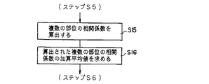
さらに、同一の測定領域で複数の相関係数を算出するのではなく、ある測定領域において相関係数を求めたら、複数の部位へ測定領域を順次移動させ、その部位の測定領域においてステップS3〜ステップS5の処理をそれぞれ行なって当該複数の部位の相関係数を算出し(ステップS15)、複数の部位の相関係数が全て算出された時点で、ステップS16の処理において算出された複数の部位の相関係数の加算平均値を求めて、ステップS6以下の処理を行なうこともできる。
【0068】
このように、同一の測定領域あるいは複数の部位からそれぞれ求められた相関係数を加算平均することにより、より正確な相関係数を求めることが可能になる。
【0069】
また、ステップS2において測定する深度及び測定する関心領域(測定領域)を設定したが、この測定領域を予め所定の領域に設定しておいてもよい(図11、ステップS2A)。
【0070】
さらに、本実施形態では、設定音速の変化に伴って遅延時間を変え、隣接走査による信号から相関係数を算出する方法について述べたが、この時新たに設定された遅延時間にて超音波画像を同時に表示してもよい。このようにすれば、超音波画像の画質(分解能)が改善されていく様子をモニタリングすることが可能になる。
【0071】
なお、上述した第1実施形態では、ゲート回路80及び指定器81を用いて所定の測定領域の受信信号のみを抽出したが、本発明はこれに限定されるものではなく、例えば、図12に第1実施形態の変形例を示す。
【0072】
この変形例は、加算器70から出力された隣接する2つ以上の受信信号を直接遅延時間制御ユニットのA/D変換器82′に送り、相関強度C(0) を求めるようになっている。
【0073】
すなわち、本変形例の遅延時間制御ユニットにおいては、加算器70の分岐出力側にA/D変換器82′が接続されている。A/D変換器82′の出力側は、第1実施形態と略同等の構成であり、また、その他の構成要素も第1実施形態と略同等であるため、その説明は省略する。
【0074】
本実施形態では、第1実施形態の図6におけるステップS1の終了後、すなわち、加算器70から出力された、隣接する2つの走査による反射信号(受信信号)e1(t)′及びe2(t)′は、直接A/D変換器82′に送られ、そのA/D変換器82′によりA/D変換された後、それぞれバッファメモリ83,83に記憶される(図13;ステップS3A)。以下、ステップS4〜ステップS8の処理が第1実施形態ど同様に行なわれ、最小の相関係数Cmin(0)及びその最小相関係数Cmin(0)に対応する最適設定音速値Vxsが求められる。そして、その最適設定音速値Vxsに基づいて最適な集束用遅延時間τfr及び最終的な最適遅延時間τが受信遅延回路66(1)〜66(M)にて新しい受信信号に与えられる。
【0075】
この変形例においても、上述した第1実施形態と同様に、生体内の音速の変化に係わらず、所定の焦点に超音波ビームを集束することができるため、超音波断層像の画質、分解能が向上する。
【0076】
(第2実施形態)
本発明の隣接する2方向からの受信信号に対して相関処理を行ない最適な遅延時間を求める遅延時間制御ユニットのその他の構成(より具体的な構成)を第2実施形態として図14に示す。
【0077】
本実施形態の遅延時間制御ユニットは、加算器70の出力側が分岐し、その分岐出力それぞれに接続されたミキサ90a,90bと、このミキサ90a,90bの出力側にそれぞれ接続されたローパスフィルタ91a,91bと、このローパスフィルタ91a,91bの出力側にそれぞれ接続されたA/D変換器92a,92bと、各A/D変換器92a,92bに2個2個ずつ接続されたバッファメモリ93…93と、各バッファメモリ93の読み出し側に接続された相関処理回路94と、相関処理回路94の出力側に接続された最適音速値検出回路95と、この最適音速値検出回路95の出力側に接続された遅延時間制御回路64とを備えている。また、遅延時間制御ユニットは、基準信号発生器96と、この基準信号発生器96の分岐出力の一方に接続されたπ/2移相器97とを有し、このπ/2移相器97の出力は一方のミキサ90aに接続され、また、基準信号発生器96の他方の出力は直接ミキサ90bに接続されている。なお、その他の構成は、第1実施形態の構成(図5)と同等であるため、その説明は省略する。
【0078】
次に、本実施形態の超音波診断装置の全体動作について、特に隣接受信信号間の相関強度に応じた遅延時間制御によるオートフォーカスの処理動作を中心に説明する。なお、第1実施形態と略同等の動作については、一部その説明を省略又は簡略化している。
【0079】
最初に、走査方向θからの受信信号e1(t)、及び走査方向θ+Δθからの受信信号e2(t)は、それぞれ次式により近似的に数式化できる。
【0080】
【数4】
【0081】
図14において、第1実施形態と同様に、図6におけるステップS1の終了後、すなわち、加算器70からの出力(隣接する2つの走査による受信信号)は、上式(4)に示したe1(t)及びe2(t)で表され、これらの受信信号e1(t)及びe2(t)は、それぞれミキサ90a及びミキサ90bに送られる。一方、基準信号発生器96から出力された超音波(角)周波数と略等しい周波数を有する基準信号sin(ω0 t)の内一方は、そのままミキサ90bの一方の入力端子を介して入力され、前記加算器出力e1(t)及びe2(t)と乗算される。
【0082】
ミキサ90bからは直流成分と 2ω0 成分が出力されるが、ローパスフィルタ91bにて 2ω0 成分は除去され、下式で示される信号が得られる。
【0083】
【数5】
【0084】
一方、基準信号発生器96から出力された基準信号sin(ω0 t)の内、他方は、π/2移相器97にて90度(π/2)位相がずれ、cos(ω0 t)としてミキサ90aの一方の入力端子を介して入力され、前記加算器出力e1(t)及びe2(t)と乗算される。さらに、ミキサ90aからの出力は、上述したミキサ90bからの出力と同様に、ローパスフィルタ91aにて高周波数成分が除去され、下式で示される信号が得られる。
【0085】
【数6】
【0086】
直交位相検波された信号は、A/D変換器92a,92bにてディジタル信号に変換された後バッファメモリ93…93に一旦記憶される。そして、バッファメモリ93…93に記憶された信号は、相関処理回路94の演算回路により、下式に示すように複素数として合成される(ステップS21)。
【0087】
【数7】
合成された複素信号E1(t) 及びE2(t) は、演算回路により下式に従って相関処理が行なわれる。
【0089】
【数8】
【数9】
E2(t) * =[ e2(t)]r−j[e2(t)]i
である(ステップS22)。この受信信号に関する設定音速値Vx1と算出された相関係数C1(0)は、相関処理回路94のメモリに一旦記憶される(ステップS23)。
【0090】
以下、第1実施形態と同様に、ステップS6以下の処理が行なわれる。すなわち、設定音速値を変えながら相関係数が順次求められ、最適設定音速値検出回路95により最小の相関係数Cmin(0)及び最適設定音速値Vxsが求められる。そして、求められた最適設定音速値Vxsに基づいて遅延時間制御回路64により最適な集束用遅延時間τfr及び最終的な最適遅延時間τが設定され、その最適遅延時間τが受信遅延回路66(1)〜66(M)にて新しい受信信号に与えられることにより、音速値に依存せずに最適に受信フォーカスされた超音波画像を表示することができる。
【0091】
以上述べたように、本実施形態によれば、第1実施形態と同様に、生体内の音速の変化に係わらず、所定の焦点に超音波ビームを集束することができるため、特に、ピクセル単位に近い高精細なダイナミック集束法を用いた場合に、非常に高分解能画質の超音波断層像を得ることができる。
【0092】
特に、本実施形態によれば、加算器から出力された受信信号をミキサ、ローパスフィルタを介して複素信号に変換してからA/D変換し、メモリに記憶しているため、信号のサンプリングやメモリへの記憶が第1実施形態の構成と比べて容易になる。
【0093】
なお、第1〜2実施形態では、各々の設定音速値に対して前掲式(3)を用い、m番目振動子の送信あるいは受信信号に与える遅延時間をそれぞれ算出する場合について述べたが、本発明はこれに限定されるものではなく、例えば遅延時間設定回路がROM(リードオンリーメモリ)等の記憶部を有し、この記憶部に予め遅延時間データを記憶させておく。そして、遅延時間制御回路のCPUは、記憶部に記憶された遅延時間データを読み出し制御して当該送信あるいは受信信号に与えることもできる。
【0094】
一般に、記憶部には焦点距離F0 (あるいは受信時間)に対してM本(M個)の振動子に与えられる遅延時間が記憶されている。すなわち、暫定的な生体内音速をVx1とすれば、焦点距離F0 に超音波を集束する場合に、m番目の振動子の送信あるいは受信信号に与えられる集束用遅延時間τf (m)は、
【数10】
【0095】
すなわち、設定音速値の順次変化に応じて遅延時間(集束用遅延時間)を制御することは、予めROM内に記憶された遅延時間データの読み出しアドレスの変更に基づく焦点距離の変化によって極めて簡単に実施可能である。
【0096】
また、集束用遅延時間τf と偏向用遅延時間τs は、それぞれに独立なROM(記憶部)を用いて記憶していることは少なく、合成遅延時間(すなわち、τf +τs )としてROMに記憶されていることが多いが、この場合でも、τf の変化に応じて全体の遅延時間τの読み出しアドレスを制御することにより、全体遅延時間の制御が可能になる。
【0097】
さらに、本実施形態においても、第1実施形態と同様に、ゲート回路を用いてある測定領域の信号のみを抽出して上述した相関処理が可能であり、また、第1実施形態で述べた各種の変形(図9〜図11)を行なうことも可能である。
【0098】
(第3実施形態)
上述した第1及び第2実施形態では、設定音速が実際の生体内音速と異なった場合に発生する集束点移動とこの移動に伴う画質劣化の改善策について説明したが、セクタ走査方式の場合には、設定音速と実際の生体内音速の際はセクタ偏向角の誤差となって現れる。すなわち、差異がΔVx1ある場合は、実際の偏向角は増大あるいは減少する。
【0099】
本実施形態における超音波診断装置は、上述した偏向角の増大あるいは減少を補正する手段を有している。
【0100】
この補正手段として、本実施形態における超音波診断装置は、図14に示す構成において、遅延時間制御回路64がROMテーブル等の記憶部を有し、この記憶部には、θ0 に対する走査角用遅延時間データτs (m)が記憶されている。セクタ偏向角θ0 と設定音速は既に示したように下式
【数11】
【0101】
例えば遅延時間制御回路64のROMテーブル等の記憶部には、θ0 に対する遅延時間データτs (m)が記憶されている。ここで、偏向角をθ0 とし、設定音速値Vx1を(ΔVx1)だけ大きくするためには、遅延時間制御回路64のCPUは、偏向角用にROM内に記憶されている走査角用遅延時間データτs (m)を「θ0 +Δθx1」の偏向に対して用いればよい。ただし、「Δθx1=−(ΔVx1/Vx1)tan θ0 」である。
【0102】
すなわち、設定音速値の順次変化に応じて遅延時間を制御することは、予めROM内に記憶された遅延時間データの読み出しアドレスの変更によって極めて簡単に実施可能である。ただし、偏向角については、他の方法も考えられる。一般に集束用遅延時間τf と偏向用遅延時間τs は、それぞれに独立なROM(記憶部)を用いて記憶していることは少なく、合成遅延時間τ(すなわち、τf +τs )としてROMに記憶されていることが多い。このような場合、変更角の補正は以下に示すように表示系にて行なうことも可能であり、ROMからの読み出し制御処理に比べて、容易に遅延時間を制御することが可能である。
【0103】
すなわち、遅延時間τs を用いた場合、設定音速値がVx1+ΔVx1であれば、上述したように、
【数12】
![]()
【0104】
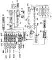
このような表示系による遅延時間制御手段を備えた超音波診断装置の構成を図16に示す。この超音波診断装置は、書き込み・読み出し制御器75aを制御するコンピュータ回路を搭載した画像メモリ制御回路100を備えている。この画像メモリ制御回路100は、最適設定音速値検出回路95′に接続されている。本実施形態の最適設定音速値検出回路95′は、相関処理回路94から送られた相関係数データに基づいて最小の相関係数及びその最小相関関数に対応する最適設定音速値を求め、さらに最適設定音速値に基づいて最適な偏向角度データ(セクタ走査角度データ)を求めて、その最適偏向角度データを画像メモリ制御回路100に送るようになっている。画像メモリ制御回路100は、送られた最適偏向角度データに基づいて、書き込み・読み出し制御器75aを制御して画像メモリ74内に書き込まれる画像信号の書き込みアドレスを制御するようになっている。なお、その他の構成は、第2実施形態の図14に示した構成と略同様であるため、その説明は省略する。
【0105】
本実施形態において、超音波パルスを生体内へ送信する場合には、まず送信レート信号発生器63から出力されたレートパルスは、送信遅延回路62(1)〜62(M)に送られ、予め設定された暫定値としての音速値Vx1に基づいて遅延時間制御回路64により算出、決定された遅延時間τf 及び遅延時間τs が与えられてMチャンネルの振動子駆動回路(パルサ)61(1)〜61(M)に供給される。すなわち、m番目の送信遅延回路62(m)において設定される遅延時間τ(m)は、「τf (m)+τs (m)」であり、τf (m)及びτs (m)は、下式のように設定される。
【0106】
【数13】
【0107】
このパルサ61(1)〜61(M)は、送信遅延回路62(1)〜62(M)の出力に応じて決定された送信タイミングにより駆動パルスを超音波振動子60(1)〜60(M)に供給し、その結果、超音波振動子60(1)〜60(M)が駆動され、超音波が生体内に放射される。
【0108】
生体内に放射された超音波の一部は、生体内の臓器の境界面あるいは生体組織の音響散乱体にて反射され、再び超音波振動子60(1)〜60(M)によって受信され、電気信号に変換される。この受信信号は、プリアンプ65(1)〜65(M)を介して増幅された後、送信時同様、設定音速値Vx1に基づいて決定された受信時の遅延時間τf 及び遅延時間τs が受信遅延回路66(1)〜66(M)により与えられて加算器70に送られる。
【0109】
加算器70からの出力(2つの走査(走査方向θ及びθ+Δθで得られた反射信号))は、前掲式(4)に示したe1(t)及びe2(t)で表され、これらの受信信号e1(t)及びe2(t)は、それぞれミキサ90a及びミキサ90b及びローパスフィルタ91a,91bを介して前掲式(5)及び式(6)に示す信号が得られる(第2実施形態、図15、ステップS20参照)。これらの信号は、A/D変換器92a,92bを介してディジタル信号としてバッファメモリ93…93に記憶された後、相関処理回路94の演算回路により、前掲式(7)に示す複素数として合成され(図15、ステップS21参照)、さらに演算回路により前掲式(8)に従って相関処理が行なわれる(図15、ステップS22〜S23参照)。
【0110】
以下、第1及び第2実施形態と同様に、設定音速値を変えながら相関係数が順次求められ、最適設定音速値検出回路95′により最小の相関係数Cmin(0)′及び最適設定音速値Vxs′が求められる(図17、ステップS30)。
【0111】
そして、最適設定音速値検出回路95′は、図17に示すように、求められた最適設定音速値Vxs′に基づいて、当該最適設定音速値Vxs′に対応する最適偏向角度(セクタ走査角度)データを上式(12)を用いて求め(ステップS31)、その最適偏向角度データを画像メモリ制御回路100に送る(ステップS32)。また同様に、最適集束点(データ取得深さ)についても、前掲式(12)によって求め、画像メモリ制御回路100に送る。
【0112】
画像メモリ制御回路100は、送られた最適偏向角度データ及び最適データ取得(サンプリング)深さデータに基づいて書き込み・読み出し制御器75aを制御して、A/D変換器73を介して送られるディジタル画像信号の画像メモリ74への書き込みアドレスを制御する(ステップS33)。すなわち、画像メモリ74へ書き込まれる(ストアされる)超音波走査信号(ディジタル画像信号)は、最適音速値での最適な走査角度及びデータサンプリング深さに対応した書き込み位置になるため、D/A変換器76を介してモニタ77に表示される超音波断層像の画質が向上する。
【0113】
以上偏向角の増減に伴う補正は、第1及び第2実施形態で説明した集束点の移動に伴う補正と同時に用いることも可能なことは言うまでもない。また、集束点の移動に伴う補正と偏向角増減に伴う補正は必ずしも同時に行なう必要はなく、特に、超音波断層像の分解能改善を目的とするならば、集束点の補正のみを行なってもよい。
【0114】
また、本実施形態においても、第1実施形態と同様に、ゲート回路を用いてある測定領域の信号のみを抽出して上述した相関処理が可能であり、また、第1実施形態で述べた各種の変形(図9〜図11)を行なうことも可能である。
【0115】
さらに、上述した実施形態では、本発明の遅延時間制御を電子セクタ走査型の超音波診断装置を用いて説明したが、本発明はこれに限定されるものではなく、電子リニア走査、電子コンベックス走査型の超音波診断装置等はいうまでもなく、アニュラアレイプローブを用いた機械走査型の超音波診断装置においても適用可能である。
【0116】
さらにまた、上述した実施形態では、遅延時間制御を受信信号に対して行なう例を示したが、送信信号と受信信号の何れにおいて行なってもよい。
【0117】
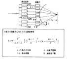
一方、本発明は隣接する2つ以上の走査に基づく受信信号間での相関処理によって超音波ビームの形状を評価するものであるが、本明細書で言う隣接とは、厳密な意味での隣接走査である必要はなく、図18に示すように、例えば順次10回の走査(走査番号1〜走査番号10)が行なわれるセクタ走査において、走査線1と走査線2の選択のみならず、走査線1と走査線3あるいは走査線1と走査線4のように、数走査線分飛び越して選択してもよい。この飛び越しが可能な範囲は、少なくとも走査線1上の受信信号と相関関係が見込める受信信号が得られた走査線までである。
【0118】
上述した走査線の最適な選択法は、ビーム幅と走査密度によって決定されるものである。さらに、複数箇所においてそれぞれ相関係数を算出し、加算平均にてより正確な値を得ようとする場合には、例えば走査1と走査4、走査2と走査5、走査3と走査6、…のような選択方法が考えられる。
【0119】
さらに、上述した実施形態では、隣接する2つの走査による2つの受信信号について相関処理が行なわれたが本発明はこれに限定されるものではなく、例えば、隣接する複数走査による複数の受信号間で相関処理を行なうこともできる。
【0120】
なお、本発明の実施形態において、ドプラ信号の血流ユニット部分の構成については、記載を省略したが、第1〜第3実施形態の各診断装置において、従来例の図19に示した血流ユニット部分を構成要素として加えてもよく、この血流ユニット部分の動作は、従来例と同等である。
【0121】
【発明の効果】
以上述べたように、本発明によれば、例えば生体内音速値が変化しても、常に所定の深さ位置に超音波ビームを集束させることができるため、その生体内音速値の変化に起因して従来の超音波断層像上に発生していた設定集束点と実際の集束点の誤差から生ずる分解能劣化が大幅に低減し、被検体の体格や検査部位等によらず常に最適な条件での診断が可能になる。また特に、本発明は、超音波ビームを所定の深さに誤差なく集束させることが可能になるため、ピクセル単位に近い高精細なダイナミック集束法を行なった場合に特に威力を発揮し、高分解能高画質の超音波断層像を得ることができ、診断精度をさらに向上させることができる。
【図面の簡単な説明】
【図1】(A)は、本発明の共通の概念を説明するための超音波診断装置の超音波送受信部分及びビーム幅の広い超音波ビームを概略的に示す図、(B)は、(A)におけるビーム幅の広い超音波ビームをラインL1 で切断した場合の断面ビーム形状を示す図。
【図2】(A)は、本発明の共通の概念を説明するための超音波診断装置の超音波送受信部分及びビーム幅の狭い超音波ビームを概略的に示す図、(B)は、(A)におけるビーム幅の狭い超音波ビームをラインL2 で切断した場合の断面ビーム形状を示す図。
【図3】ビーム幅と相関強度の関係を示すグラフ。
【図4】(a)は、走査方向θからの受信信号e1(t)の信号波形を示す図、(b)は、走査方向(θ+Δθ)からの受信信号e2(t)の信号波形を示す図、(c)は、相関係数を示す式を表す図。
【図5】第1実施形態に係わる超音波診断装置の全体構成を概略的に示すブロック図。
【図6】第1実施形態における超音波診断装置の遅延時間制御処理の一例を示す概略フローチャート。
【図7】超音波断層像上で指定される測定領域の一例を示す図。
【図8】設定音速と相関強度との関係の一例を示すグラフ。
【図9】第1実施形態における超音波診断装置の相関強度に応じた遅延時間制御処理の一例を示す概略フローチャート。
【図10】第1実施形態における超音波診断装置の遅延時間制御処理の一例を示す概略フローチャート。
【図11】第1実施形態における超音波診断装置の遅延時間制御処理の一例を示す概略フローチャート。
【図12】第1実施形態の変形例における超音波診断装置の全体構成を概略的に示すブロック図。
【図13】第1実施形態の変形例における超音波診断装置の遅延時間制御処理の一例を示す概略フローチャート。
【図14】第2実施形態の変形例における超音波診断装置の全体構成を概略的に示すブロック図。
【図15】第2実施形態における超音波診断装置の遅延時間制御処理の一例を示す概略フローチャート。
【図16】第3実施形態の変形例における超音波診断装置の全体構成を概略的に示すブロック図。
【図17】第3実施形態における超音波診断装置の遅延時間制御処理の一例を示す概略フローチャート。
【図18】隣接走査における走査線の選択例を説明するための図。
【図19】従来の超音波診断装置の全体構成を示すブロック図。
【図20】電子集束法の原理を説明するための図。
【図21】ダイナミック集束法の原理を説明するための図。
【図22】従来のダイナミック集束法の問題点を説明するための図。
【符号の説明】
50 送信器
51 受信機
52 表示器
53 遅延回路
54 振動子
55 遅延時間制御回路
60(1)〜60(M) 超音波振動子
61(1)〜61(M) 振動子駆動回路(パルサ)
62(1)〜62(M) 送信遅延回路
63 送信レート信号発生器
64 遅延時間制御回路
65(1)〜65(M) プリアンプ
66(1)〜66(M) 受信遅延回路
70 加算器
71 対数増幅器
72 検波回路
73 A/D変換器
74 画像メモリ
75、75a 書き込み・読み出し制御回路
76 D/A変換器
77 テレビモニタ
82 A/D変換器
83,83 バッファメモリ
84,94 相関処理回路
85,95 最適設定音速値検出回路
90a,90b ミキサ
91a,91b ローパスフィルタ
92a,92b A/D変換器
93 バッファメモリ
96 基準信号発生器
97 π/2移相器
100 画像メモリ制御回路[0001]
BACKGROUND OF THE INVENTION
The present invention relates to a so-called ultrasonic diagnostic apparatus that displays a tomographic image in the body using an ultrasonic signal and a delay time optimization method that optimizes a delay time given to the ultrasonic signal, and in particular, a sound velocity value in a living body. The present invention relates to an ultrasonic diagnostic apparatus and a delay time optimizing method that automatically corrects ultrasonic beam pattern degradation caused by uncertainty in order to achieve high resolution.
[0002]
[Prior art]
An ultrasonic diagnostic method that radiates an ultrasonic signal (also called an ultrasonic beam or ultrasonic pulse) into the body of a subject and obtains biological information by reflected waves from each tissue in the subject is an ultrasonic tomography method. In recent years, rapid progress has been made by the development of two technologies of the ultrasonic Doppler method. The most widely used electronic scanning device today uses an array type (array type) ultrasonic transducer (ultrasonic transducer), which is electronically controlled at high speed to scan in real time. It was possible.
[0003]
For example, a conventional example of a sector electronic scanning ultrasonic diagnostic apparatus is shown in FIG. 19 using a block diagram. Let M be the number of elements of the transducers arranged in the ultrasonic probe (vibrators 4 (1) to 4 (M)). When transmitting an ultrasonic pulse into a living body (or within a medium), first, a rate pulse for determining a repetition frequency of the ultrasonic pulse is output from the transmission
[0004]
That is, the delay time τ (m) set in the mth delay circuit 2 (m) is τ f (M) + τ s (M) and τ f And τ s Is set as follows (τ f (See FIG. 3 for (m)).
[0005]
[Expression 1]
[0006]
In the pulsers 3 (1) to 3 (M), drive pulses for generating the ultrasonic waves by driving the ultrasonic transducers 4 (1) to 4 (M) are generated, and the transmission timing of the drive pulses is as follows. It is determined by the outputs of the transmission delay circuits 2 (1) to 2 (M). Outputs of the pulsars (driving circuits) 3 (1) to 3 (M) are supplied to the ultrasonic transducers 4 (1) to 4 (M), and the ultrasonic transducers 4 (1) to 4 (M). To generate ultrasonic waves.
[0007]
A part of the ultrasonic wave generated from the ultrasonic transducers 4 (1) to 4 (M) and emitted into the living body is reflected by the boundary surface of the organ in the living body or the acoustic scatterer of the living tissue, and again. The signals are received by the ultrasonic transducers 4 (1) to 4 (M) and converted into electric signals. This received signal is amplified via the preamplifiers 5 (1) to 5 (M), and then, similarly to the transmission, the delay time for determining the convergence distance of the ultrasonic beam at the reception and the deflection angle of the ultrasonic beam are determined. Is sent to the adder 7 via the
[0008]
The signal stored in the
[0009]
On the other hand, the output of the adder 7 is sent to two quadrature detection circuits. That is, the output of the adder 7 is first sent to the mixer circuits 14-1 and 14-2. The
[0010]
On the other hand, in order to calculate the Doppler signal, it is necessary to continuously scan the same part and use a plurality of signals at that time. A plurality of signals obtained by the plurality of scans are temporarily stored in a memory (not shown), and when a predetermined number of data are obtained, the frequency analysis of the Doppler signal is performed by the
[0011]
The physical quantities displayed in the ultrasonic blood flow imaging method (ultrasonic Doppler method) are the center of the spectrum (that is, the average value of the flow velocity) and the dispersion value of the spectrum (that is, the state of disturbance of the flow velocity). These calculations are performed by the
[0012]
As described above, in the conventional ultrasonic diagnostic apparatus, the method of focusing the ultrasonic beam in at least one of transmission and reception is used in order to increase the azimuth resolution. In particular, in an electronic scanning type array type transducer, an electron focusing method based on delay time control of transmission / reception signals is generally used. The ultrasonic diagnostic apparatus has a
[0013]
However, the problem with the electron focusing method that focuses the ultrasonic beam is that the beam diffuses at a location (depth) away from the focusing point and the resolution is lowered. As a method for solving this problem, a dynamic focusing method has been conventionally used. The dynamic focusing method is a method of performing delay time control so that the focusing point continuously moves in the depth direction with time during reception, and the reflected signal is always obtained from the region where the received ultrasonic beam is focused. . The principle will be described with reference to FIG.
[0014]
In a range in which a reflected signal with a distance from the transducer of 0 to r1 is obtained (that is, a range from
[0015]
[Problems to be solved by the invention]
In the description of the dynamic focusing method described above, the case where the focusing point at the time of dynamic focusing changes in three stages of f1 to f3 has been described. It has become possible to set a continuous focusing point for each pixel of the image memory.
[0016]
When continuously setting a focusing point using the dynamic focusing method, the reception delay time is set using the above-described equation (1). The delay time determination parameter shown in the equation (1) is used. It has been conventionally known that the in-vivo sound velocity value V varies depending on organs, for example, there is a report of “V = 1560 m / sec” for muscles and “V = 1480 m / sec” for fats. There are also significant differences among the subjects.
[0017]
In this way, the in-vivo sound speed value is an amount that cannot be universally determined in practice, so that the focusing point cannot be determined, which hinders the dynamic focusing method.
[0018]
That is, given delay time τ f Always F for (m) 0 Since V = constant, if there is a difference of about 5% in the sound speed value as in the case of fat and muscle, the movement of the focusing point at the focusing point of 100 mm is 5 mm, which is an amount that cannot be ignored. Therefore, in such a case, it is difficult to say that the reception from the focusing point is necessarily displayed and displayed, and as a result, the image quality is deteriorated.
[0019]
When the set sound speed value of the apparatus is equal to the actual sound speed value, as shown in FIG. 22B, a range in which a reflected signal having a distance from the transducer of 0 to r1 can be obtained (that is, time 0). The actual focal length f1 ′ is determined to be approximately the midpoint of 0−r1. Similarly, in a range where a reflected signal having a distance from r1 to r2 is obtained (that is, a range from time 2r1 / V to 2r2 / V), the actual focal length f2 'is approximately at the midpoint of r1 -r2, and When a reflected signal is obtained from a range of distance r2 or more (that is, a range of time 2r2 / V or more), the actual focal length f3 'is determined to be after r3.
[0020]
On the other hand, for example, when the actual in-vivo sound speed value is larger than the set sound speed value in the apparatus, the actual focusing points f1 ′ to f3 ′ are set to the set focusing points f1 to f1 as shown in FIG. f1 ′ <f1, f2 ′ <f2, and f3 ′ <f3 with respect to f3 (generally f1 = r1 / 2, f2 = (r1 + r2) / 2, f3> r3), and the difference between the sound speed values is particularly large. In some cases, f2 '<r1 occurred, and the effect of the dynamic focusing method was not utilized.
[0021]
The present invention has been made to solve the above-described problems, and an object of the present invention is to make the ultrasonic tomography to maximize the effects of the dynamic focusing method by constantly matching the set focusing point with the actual focusing point. The object is to further improve the image quality of the image.
[0022]
[Means for Solving the Problems]
In order to solve the above-described problem, in the present invention, for example, an amount indicating a correlation between signals in a region (arbitrary depth) designated on a tomographic image, for example, among received signals on adjacent scanning lines. (Correlation amount) is calculated. Based on the calculated correlation amount, the degree of convergence of the received signal (the depth position of the reception focus, etc.) is controlled.
[0023]
That is, the amount of correlation calculated each time is compared while sequentially changing parameter values such as in-vivo sound velocity values that govern the degree of convergence of the received signal. Then, a parameter value (optimum value) that minimizes the correlation amount is searched, and a parameter that determines the degree of convergence (for example, the degree of change in the delay time or the depth position of the reception focus) is optimized based on the parameter value. It is configured.
[0024]
With this configuration, the parameter value (in-vivo sound speed value) that minimizes the amount of correlation between received signals on adjacent scanning lines, for example, every predetermined period, as necessary, such as by diagnostic site or by subject. Based on this, it is possible to set the focusing parameter (delay time, change degree of reception focus depth position, etc.), so the ultrasonic beam reception focus degree (depth position, etc.) Regardless of whether it is constant or not. Therefore, for example, even in high-definition dynamic reception focusing performed on a pixel-by-pixel basis, only the received signals from the focal point are always collected, and an ultrasonic tomographic image with higher resolution and higher image quality is obtained based on those received signals. be able to.
[0025]
In the present invention, the ultrasonic signal is repeatedly scanned a plurality of times on the same scanning line, and the correlation for each repeated scanning is based on the received signals on the plurality of scanning lines obtained for each of the repeated scanning. Calculate the quantity. An accurate correlation amount with little error can be obtained by averaging the calculated correlation amounts for each repeated scan.
[0026]
Furthermore, in the present invention, the correlation amount for each different part is calculated based on the received signals on the scanning lines of the different parts on the cross section, and the calculated correlation amount for each repeated scanning is added and averaged to reduce errors. An accurate correlation amount can be obtained.
[0027]
On the other hand, in order to solve the above-described problem, in the present invention, when scanning is performed by deflecting an ultrasonic signal such as sector scanning, the received signal on an adjacent scanning line is designated on a tomographic image, for example. An amount (correlation amount) indicating a correlation between signals in the region (arbitrary depth) is calculated. The deflection angle of the ultrasonic signal is controlled based on the calculated correlation amount.
[0028]
That is, the amount of correlation calculated each time is compared while sequentially changing parameter values such as in-vivo sound velocity values that govern the deflection angle of the ultrasonic signal. Then, a parameter value (optimum value) that minimizes the correlation amount is searched, a parameter (for example, delay time) for determining a deflection angle based on the parameter value, and a parameter (for the depth position) for determining a reception focus depth position. The degree of change, etc.) is controlled.
[0029]
With this configuration, for example, when performing sector scanning, the parameter value that minimizes the amount of correlation between received signals on adjacent scanning lines, for example, at regular intervals, as necessary, such as by diagnostic site or by subject. Since parameters (delay time, degree of change in depth position, etc.) can be set based on (in vivo sound speed value), the deflection angle of the ultrasonic beam is always constant regardless of changes in in vivo sound speed value, etc. In addition, the reception focus depth position can be optimized. Therefore, a high-resolution, high-quality ultrasonic tomographic image can be obtained.
[0030]
Furthermore, the writing of the ultrasonic scanning signal to the scan conversion memory can be controlled as the deflection angle control means. That is, by obtaining the deflection angle data corresponding to the parameter value based on the parameter value that minimizes the correlation amount, and changing the write address of the received signal to the memory according to the deflection angle data, It is possible to correct an error in deflection angle caused by a change in value.
[0031]
DETAILED DESCRIPTION OF THE INVENTION
First, the common concept of the present invention will be described with reference to FIGS. 1 and 2 are schematic views (partially sectional views) showing an ultrasonic transmission / reception part of an ultrasonic diagnostic apparatus that performs sector electronic scanning, and includes a
[0032]
Now, in an ultrasonic diagnostic apparatus that performs sector electronic scanning, the received signals (e1 (t), e1 (t), e1 (t), e2 (t)), when the beam width near the focusing point “A” is wide (when focusing is not performed as planned; see FIGS. 1A and 1B), “B” When the beam width is narrow (when focusing is performed more accurately; see FIGS. 2A and 2B), the relationship between the beam width and the correlation function will be described.
[0033]
In general, the interval between scanning lines adjacent to the ultrasonic beam width (scanning interval; here, Δθ) is set small. For this reason, the two adjacent ultrasonic beams Ba and Bb have a part of the area in common as shown in FIG. 1, and this common part is larger as the beam width is wider as the focusing is insufficient. In other words, the wider the beam width (the larger the beam spread state, the greater the beam side rope level spread), the more commonly received information from the same scatterer is included in the received signal obtained by each scan. Therefore, the correlation strength (correlation coefficient) between the respective received signals becomes larger.
[0034]
On the other hand, as the focusing is performed more completely, as shown in FIG. 2, the common part of the adjacent ultrasonic beams Ba ′ and Bb ′ becomes narrower, and the signals obtained by the respective scans become smaller. The correlation coefficient of becomes smaller. That is, the beam width and the correlation strength C (0) are qualitatively as shown in FIG.
[0035]
The correlation coefficient C (0) of the received signal e1 (t) in the θ direction and the received signal e2 (t) from the θ + Δθ direction (both waveforms are shown in FIGS. 4A and 4B) is as follows. It is shown by an equation (see FIG. 4C).
[0036]
[Expression 2]
[0037]
That is, it can be seen that the beam width near the focal point can be controlled by controlling the correlation coefficient C (0) of two or more adjacent ultrasonic beams.
[0038]
The present invention utilizes the above-described properties to reduce the above-described focusing point error by controlling the delay time for obtaining each focusing point in dynamic focusing, for example, so that the beam width of the focusing point is minimized. It is configured as follows.
[0039]
Next, FIG. 5 shows a first embodiment for briefly explaining the outline of the processing procedure of the autofocus method based on the correlation processing.
[0040]
This ultrasonic diagnostic apparatus is a diagnostic apparatus that performs sector scanning, for example, and includes arrayed ultrasonic transducers 60 (1) to 60 (M) that are electro-acoustic transducers in which M transducers are arranged in a straight line. Have. The array-
[0041]
The transmission system includes M-channel pulsers (vibrator drive circuits) 61 (1) to 61 (M) that output drive pulses for driving the array-type transducers 60 (1) to 60 (M), and the pulsers. Transmission delay circuits 62 (1) to 62 (M) connected to 61 (1) to 61 (M) and delay-controlling the drive pulse output timing of the pulsars 61 (1) to 61 (M), and each transmission delay A transmission rate signal generator 63 for sending rate control rate pulses to the circuits 62 (1) to 62 (M), and a delay for individually controlling the delay time given by each of the transmission delay circuits 62 (1) to 62 (M) And a
[0042]
The transmission delay circuits 62 (1) to 62 (M) are focused on the ultrasonic beam during transmission controlled by the delay
[0043]
That is, the delay time τ (m) set in the m (m <M) -th delay circuit 62 (m) is τ f (M) + τ s (M) and τ f (M) and τ s (M) is set as follows (τ f (See FIG. 20 for (m)).
[0044]
[Equation 3]
[0045]
The receiving system includes preamplifiers 65 (1) to 65 (M) that amplify the received signals received by the arrayed transducers 60 (1) to 60 (M) and converted into electrical signals, and the preamplifiers 65 (1). ) To 65 (M), M-channel reception delay circuits 66 (1) to 66 (M) for receiving the received signals amplified with different delay times, and each reception delay circuit 66 (1). ) To 66 (M), the delay
[0046]
The reception delay circuits 66 (1) to 66 (M) are controlled by the delay
[0047]
Further, the reception system adds and synthesizes the reception signals output from the reception delay circuits 66 (1) to 66 (M), and logarithmically amplifies (compresses) the reception signal added and synthesized by the adder 70. ) A
[0048]
On the other hand, the ultrasonic diagnostic apparatus includes a unit that controls at least one of the transmission delay time and the reception delay time according to the correlation strength between adjacent reception signals. That is, the delay time control unit is connected to the delay
[0049]
Next, the overall operation of the ultrasonic diagnostic apparatus according to the present embodiment will be described focusing on the autofocus processing operation based on the delay time control according to the correlation strength between adjacent received signals.
[0050]
When transmitting an ultrasonic pulse into the living body, the rate pulse output from the transmission rate signal generator 63 is sent to the transmission delay circuits 62 (1) to 62 (M). The rate pulse is transmitted from the transmission delay circuit 62 (1) to 62 (M) as a sound speed value V as a preset provisional value. x1 The delay time τ calculated and determined by the delay
[0051]
Each pulsar 61 (1) to 61 (M) transmits a drive pulse to each ultrasonic transducer 60 (1) to 60 (1) to 60 at a transmission timing determined according to the output of the transmission delay circuit 62 (1) to 62 (M). As a result, the ultrasonic transducers 60 (1) to 60 (M) are driven to emit an ultrasonic beam into the living body.
[0052]
A part of the ultrasonic beam radiated into the living body is reflected by the boundary surface of the organ in the living body or the acoustic scatterer of the living tissue, and received again by the ultrasonic transducers 60 (1) to 60 (M). , Converted into an electrical signal. This received signal is amplified via the preamplifiers 65 (1) to 65 (M), and similarly to the transmission, the reception delay time τ determined based on the set sound velocity value VX1. f And delay time τ s Are given by the reception delay circuits 66 (1) to 66 (M) and sent to the adder 70 (FIG. 6, step S1).
[0053]
The output of the
[0054]
Subsequently, an approximate depth to be measured and a region of interest (hereinafter referred to as a measurement region) are set on the ultrasonic tomogram (see FIG. 7) obtained based on the provisional delay time Vx1. In this case, the measurement area can be set by a designator 81 such as a trackball or a joystick (step S2).
[0055]
Of the output of the
[0056]
The reception signal e1 (t) in the scanning direction θ and the reception signal e2 (t) in the scanning direction θ + Δθ, which are A / D converted by the A /
[0057]
Then, the received signals e1 (t) and e2 (t) stored in the
[0058]
Next, the set sound velocity value V x1 A new set sound velocity value V increased (or decreased) by a predetermined amount with respect to x2 On the other hand, the delay
[0059]
That is, the received signals e1 (t) ′ and e2 (t) ′ obtained by two adjacent scans (scanning direction (θ), (θ + Δθ)) among echo signals from substantially the same area as the designated area are After being stored in the
[0060]
In this way, the set sound velocity value V x1 , V x2 ... V xn Are sequentially changed within a predetermined range and the above-described processing (steps S3 to S5) is performed, so that the sound velocity value V is obtained. x1 , V x2 ... V xn Correlation coefficients C1 (0), C2 (0),..., Cn (0) corresponding to are calculated by the arithmetic circuit of the
[0061]
Then, the optimum set sound
[0062]
Obtained optimum sound speed value V xs Based on the delay
[0063]
As described above, according to the present embodiment, even if the sound speed in the living body changes, it is possible to set an optimum sound speed value that always minimizes the correlation coefficient of the received signal, and to this optimum sound speed value, Based on this, it is possible to determine the focusing delay time of the received signal, so that the ultrasonic beam can always be focused at a predetermined focal point regardless of the change in the sound speed in the living body. As a result, the image quality and resolution of the ultrasonic tomographic image are improved.
[0064]
In particular, when using a high-definition dynamic focusing method that continuously controls the delay time according to different depths (especially in units of pixels), each focusing point is defined as a data acquisition site regardless of the in-vivo sound speed value. Since they coincide, an ultrasonic tomographic image with very high resolution and high image quality can be obtained.
[0065]
In the above-described embodiment, the case where the delay time corresponding to the optimum set sound speed value is given to the reception signal has been described. However, the present invention is not limited to this, and the same delay time is given to the transmission signal. be able to.
[0066]
Also, if the value is unstable by only one correlation coefficient calculation for each set sound speed value, after the processing in step S5, the processing in steps S3 to S5 is repeated a predetermined number of times in the same measurement region. (FIG. 9; Step S10), and when the predetermined number of correlation coefficients are calculated, the addition average of the predetermined number of correlation coefficients calculated in the process of Step S11 is obtained, and Step S6 and subsequent steps are calculated. Can also be performed.
[0067]
Furthermore, instead of calculating a plurality of correlation coefficients in the same measurement area, if the correlation coefficient is obtained in a certain measurement area, the measurement area is sequentially moved to a plurality of parts, and steps S3 to S3 are performed in the measurement area of the part. The processing of step S5 is performed to calculate the correlation coefficients of the plurality of parts (step S15), and when all the correlation coefficients of the plurality of parts are calculated, the plurality of parts calculated in the processing of step S16 It is also possible to obtain the addition average value of the correlation coefficients and perform the processing from step S6 onward.
[0068]
In this way, it is possible to obtain a more accurate correlation coefficient by averaging the correlation coefficients respectively obtained from the same measurement region or a plurality of parts.
[0069]
In addition, although the depth to be measured and the region of interest (measurement region) to be measured are set in step S2, this measurement region may be set in advance as a predetermined region (FIG. 11, step S2A).
[0070]
Further, in the present embodiment, the method of calculating the correlation coefficient from the signal by the adjacent scanning by changing the delay time according to the change of the set sound speed has been described. However, at this time, the ultrasonic image is newly set at the delay time set. May be displayed simultaneously. In this way, it is possible to monitor how the image quality (resolution) of the ultrasonic image is improved.
[0071]
In the first embodiment described above, only the received signal in the predetermined measurement region is extracted using the
[0072]
In this modification, two or more adjacent received signals output from the
[0073]
That is, in the delay time control unit of this modification, an A /
[0074]
In the present embodiment, after the end of step S1 in FIG. 6 of the first embodiment, that is, the reflected signals (received signals) e1 (t) ′ and e2 (t) output from the
[0075]
In this modified example as well, as in the first embodiment described above, the ultrasonic beam can be focused at a predetermined focal point regardless of the change in the sound speed in the living body. improves.
[0076]
(Second Embodiment)
FIG. 14 shows another configuration (more specific configuration) of a delay time control unit that performs correlation processing on received signals from two adjacent directions and obtains an optimum delay time according to the present invention.
[0077]
In the delay time control unit of this embodiment, the output side of the
[0078]
Next, the overall operation of the ultrasonic diagnostic apparatus according to the present embodiment will be described focusing on the autofocus processing operation based on the delay time control according to the correlation strength between adjacent received signals. Note that some of the operations that are substantially the same as those in the first embodiment are omitted or simplified.
[0079]
First, the received signal e1 (t) from the scanning direction θ and the received signal e2 (t) from the scanning direction θ + Δθ can be approximated by the following equations, respectively.
[0080]
[Expression 4]
[0081]
In FIG. 14, similarly to the first embodiment, after the end of step S1 in FIG. 6, that is, the output from the adder 70 (received signals by two adjacent scans) is e1 shown in the above equation (4). (t) and e2 (t), and these received signals e1 (t) and e2 (t) are sent to the mixer 90a and the
[0082]
From the
[0083]
[Equation 5]
[0084]
On the other hand, the reference signal sin (ω 0 The other of t) is 90 degrees (π / 2) out of phase by the π / 2
[0085]
[Formula 6]
[0086]
The quadrature phase detected signal is converted into a digital signal by the A /
[0087]
[Expression 7]
The combined complex signals E1 (t) and E2 (t) are subjected to correlation processing according to the following expression by an arithmetic circuit.
[0089]
[Equation 8]
[Equation 9]
E2 (t) * = [E2 (t)] r-j [e2 (t)] i
(Step S22). The set sound velocity value V related to this received signal x1 The calculated correlation coefficient C1 (0) is temporarily stored in the memory of the correlation processing circuit 94 (step S23).
[0090]
Thereafter, similarly to the first embodiment, the processes in and after step S6 are performed. That is, the correlation coefficient is obtained sequentially while changing the set sound speed value, and the optimum correlation value Cmin (0) and the optimum set sound speed value V are detected by the optimum set sound speed
[0091]
As described above, according to the present embodiment, as in the first embodiment, the ultrasonic beam can be focused at a predetermined focal point regardless of the change in the sound speed in the living body. When a high-definition dynamic focusing method close to is used, an ultrasonic tomographic image with very high resolution image quality can be obtained.
[0092]
In particular, according to the present embodiment, the received signal output from the adder is converted into a complex signal via a mixer and a low-pass filter and then A / D converted and stored in the memory. Storage in the memory becomes easier as compared with the configuration of the first embodiment.
[0093]
In the first and second embodiments, the case has been described in which the delay time given to the transmission or reception signal of the mth transducer is calculated using the above equation (3) for each set sound velocity value. The invention is not limited to this. For example, the delay time setting circuit has a storage unit such as a ROM (read only memory), and delay time data is stored in advance in the storage unit. Then, the CPU of the delay time control circuit can read out and control the delay time data stored in the storage unit and give it to the transmission or reception signal.
[0094]
In general, the storage unit has a focal length F. 0 A delay time given to M (M) transducers with respect to (or reception time) is stored. That is, if the provisional in-vivo sound speed is Vx1, the focal length F 0 A focusing delay time τ given to the transmission or reception signal of the mth transducer when focusing the ultrasonic wave on f (M)
[Expression 10]
[0095]
That is, controlling the delay time (focusing delay time) in accordance with the sequential change of the set sound velocity value is very easy by changing the focal length based on the change of the read address of the delay time data stored in the ROM in advance. It can be implemented.
[0096]
Also, focusing delay time τ f And deflection delay time τ s Are rarely stored using independent ROMs (storage units), and the combined delay time (ie, τ f + Τ s ) Is often stored in the ROM, but even in this case, τ f By controlling the read address of the entire delay time τ in accordance with the change in the total delay time, the overall delay time can be controlled.
[0097]
Further, in the present embodiment, as in the first embodiment, it is possible to perform the above-described correlation processing by extracting only a signal in a certain measurement region using a gate circuit. In addition, the various processing described in the first embodiment can be performed. It is also possible to perform the modification (FIGS. 9 to 11).
[0098]
(Third embodiment)
In the first and second embodiments described above, the focus point movement that occurs when the set sound speed is different from the actual in-vivo sound speed and the measures for improving the image quality deterioration due to this movement have been described. Appears as an error in the sector deflection angle between the set sound speed and the actual in-vivo sound speed. That is, the difference is ΔV x1 In some cases, the actual deflection angle increases or decreases.
[0099]
The ultrasonic diagnostic apparatus according to the present embodiment has means for correcting the increase or decrease in the deflection angle described above.
[0100]
As the correction means, in the ultrasonic diagnostic apparatus according to the present embodiment, the delay
[Expression 11]
[0101]
For example, in the storage unit such as the ROM table of the delay
[0102]
That is, it is very easy to control the delay time according to the sequential change of the set sound velocity value by changing the read address of the delay time data stored in the ROM in advance. However, other methods can be considered for the deflection angle. Generally focusing delay time τ f And deflection delay time τ s Are rarely stored using independent ROMs (storage units), and the combined delay time τ (ie, τ f + Τ s ) Is often stored in the ROM. In such a case, the correction of the change angle can be performed by a display system as described below, and the delay time can be easily controlled as compared with the read control process from the ROM.
[0103]
That is, the delay time τ s Is used, the set sound velocity value is V x1 + ΔV x1 Then, as mentioned above,
[Expression 12]
![]()
[0104]
FIG. 16 shows the configuration of an ultrasonic diagnostic apparatus provided with such a display system delay time control means. This ultrasonic diagnostic apparatus includes an image
[0105]
In this embodiment, when transmitting an ultrasonic pulse into the living body, first, the rate pulse output from the transmission rate signal generator 63 is sent to the transmission delay circuits 62 (1) to 62 (M), Sound velocity value V as a provisional value x1 The delay time τ calculated and determined by the delay
[0106]
[Formula 13]
[0107]
The pulsars 61 (1) to 61 (M) send drive pulses to the ultrasonic transducers 60 (1) to 60 () according to the transmission timing determined according to the outputs of the transmission delay circuits 62 (1) to 62 (M). M), as a result, the ultrasonic transducers 60 (1) to 60 (M) are driven, and ultrasonic waves are emitted into the living body.
[0108]
A part of the ultrasonic wave radiated into the living body is reflected by the boundary surface of the organ in the living body or the acoustic scatterer of the living tissue, and received again by the ultrasonic transducers 60 (1) to 60 (M), It is converted into an electrical signal. This received signal is amplified through the preamplifiers 65 (1) to 65 (M) and then the set sound speed value V as in the transmission. x1 Delay time τ at the time of reception determined based on f And delay time τ s Are given by the reception delay circuits 66 (1) to 66 (M) and sent to the
[0109]
Outputs from the adder 70 (two scans (reflected signals obtained in the scanning directions θ and θ + Δθ)) are represented by e1 (t) and e2 (t) shown in the above equation (4), and these receptions are received. As the signals e1 (t) and e2 (t), the signals shown in the above equations (5) and (6) are obtained through the mixer 90a, the
[0110]
Thereafter, as in the first and second embodiments, the correlation coefficient is sequentially obtained while changing the set sound speed value, and the minimum correlation coefficient Cmin (0) ′ and the optimum set sound speed are obtained by the optimum set sound speed
[0111]
Then, as shown in FIG. 17, the optimum set sound speed
[0112]
The image
[0113]
It goes without saying that the correction accompanying the increase / decrease of the deflection angle can be used simultaneously with the correction accompanying the movement of the focusing point described in the first and second embodiments. Further, the correction accompanying the movement of the focusing point and the correction accompanying the increase / decrease of the deflection angle do not necessarily have to be performed at the same time. .
[0114]
Also in the present embodiment, as in the first embodiment, it is possible to extract only signals in a certain measurement region using a gate circuit and perform the above-described correlation processing, and the various types of processing described in the first embodiment. It is also possible to perform the modification (FIGS. 9 to 11).
[0115]
Furthermore, in the above-described embodiment, the delay time control of the present invention has been described using an electronic sector scanning type ultrasonic diagnostic apparatus, but the present invention is not limited to this, and electronic linear scanning, electronic convex scanning. Needless to say, a type of ultrasonic diagnostic apparatus is applicable to a mechanical scanning type ultrasonic diagnostic apparatus using an annular array probe.
[0116]
Furthermore, in the above-described embodiment, an example in which the delay time control is performed on the reception signal has been described. However, the delay time control may be performed on either the transmission signal or the reception signal.
[0117]
On the other hand, according to the present invention, the shape of the ultrasonic beam is evaluated by correlation processing between received signals based on two or more adjacent scans. For example, as shown in FIG. 18, in the sector scan in which 10 scans (scan
[0118]
The optimum scanning line selection method described above is determined by the beam width and scanning density. Further, when calculating correlation coefficients at a plurality of locations and obtaining more accurate values by averaging, for example, scan 1 and scan 4, scan 2 and scan 5, scan 3 and scan 6,... The following selection method can be considered.
[0119]
Further, in the above-described embodiment, the correlation processing is performed on two received signals by two adjacent scans. However, the present invention is not limited to this, and for example, between a plurality of received signals by adjacent plural scans. Correlation processing can also be performed with.
[0120]
In addition, in embodiment of this invention, although description was abbreviate | omitted about the structure of the blood flow unit part of a Doppler signal, in each diagnostic apparatus of 1st-3rd embodiment, the blood flow shown in FIG. 19 of the prior art example A unit portion may be added as a component, and the operation of this blood flow unit portion is equivalent to the conventional example.
[0121]
【The invention's effect】
As described above, according to the present invention, for example, even if the in-vivo sound speed value changes, the ultrasonic beam can always be focused at a predetermined depth position. As a result, the resolution degradation caused by the error between the set focus point and the actual focus point generated on the conventional ultrasonic tomogram is greatly reduced, and the optimal conditions are always maintained regardless of the size of the subject and the examination site. Can be diagnosed. In particular, the present invention makes it possible to focus an ultrasonic beam to a predetermined depth without error, so that it is particularly effective when a high-definition dynamic focusing method close to a pixel unit is performed. A high-quality ultrasonic tomographic image can be obtained, and diagnostic accuracy can be further improved.
[Brief description of the drawings]
FIG. 1A is a diagram schematically showing an ultrasonic transmission / reception part and an ultrasonic beam having a wide beam width of an ultrasonic diagnostic apparatus for explaining a common concept of the present invention, and FIG. The figure which shows the cross-sectional beam shape at the time of cut | disconnecting the ultrasonic beam with a wide beam width in A) by line L1.
FIG. 2A is a diagram schematically showing an ultrasonic transmission / reception part and an ultrasonic beam having a narrow beam width of an ultrasonic diagnostic apparatus for explaining a common concept of the present invention, and FIG. The figure which shows the cross-sectional beam shape at the time of cut | disconnecting the ultrasonic beam with a narrow beam width in A) by the line L2.
FIG. 3 is a graph showing the relationship between beam width and correlation intensity.
4A is a diagram showing a signal waveform of a reception signal e1 (t) from the scanning direction θ, and FIG. 4B is a signal waveform of a reception signal e2 (t) from the scanning direction (θ + Δθ). (C) is a figure showing the formula which shows a correlation coefficient.
FIG. 5 is a block diagram schematically showing the overall configuration of the ultrasonic diagnostic apparatus according to the first embodiment.
FIG. 6 is a schematic flowchart showing an example of a delay time control process of the ultrasonic diagnostic apparatus according to the first embodiment.
FIG. 7 is a diagram showing an example of a measurement region designated on an ultrasonic tomographic image.
FIG. 8 is a graph showing an example of the relationship between the set sound speed and the correlation strength.
FIG. 9 is a schematic flowchart showing an example of a delay time control process according to the correlation strength of the ultrasonic diagnostic apparatus according to the first embodiment.
FIG. 10 is a schematic flowchart illustrating an example of a delay time control process of the ultrasonic diagnostic apparatus according to the first embodiment.
FIG. 11 is a schematic flowchart illustrating an example of a delay time control process of the ultrasonic diagnostic apparatus according to the first embodiment.
FIG. 12 is a block diagram schematically showing an overall configuration of an ultrasonic diagnostic apparatus according to a modification of the first embodiment.
FIG. 13 is a schematic flowchart showing an example of a delay time control process of the ultrasonic diagnostic apparatus according to a modification of the first embodiment.
FIG. 14 is a block diagram schematically showing an overall configuration of an ultrasonic diagnostic apparatus according to a modification of the second embodiment.
FIG. 15 is a schematic flowchart showing an example of a delay time control process of the ultrasonic diagnostic apparatus according to the second embodiment.
FIG. 16 is a block diagram schematically showing an overall configuration of an ultrasonic diagnostic apparatus according to a modification of the third embodiment.
FIG. 17 is a schematic flowchart illustrating an example of a delay time control process of the ultrasonic diagnostic apparatus according to the third embodiment.
FIG. 18 is a diagram for explaining an example of scanning line selection in adjacent scanning.
FIG. 19 is a block diagram showing the overall configuration of a conventional ultrasonic diagnostic apparatus.
FIG. 20 is a diagram for explaining the principle of an electron focusing method;
FIG. 21 is a diagram for explaining the principle of the dynamic focusing method;
FIG. 22 is a diagram for explaining problems of a conventional dynamic focusing method.
[Explanation of symbols]
50 transmitter
51 Receiver
52 Display
53 Delay circuit
54 vibrator
55 Delay time control circuit
60 (1) -60 (M) ultrasonic transducer
61 (1) to 61 (M) vibrator drive circuit (pulsar)
62 (1) to 62 (M) Transmission delay circuit
63 Transmission rate signal generator
64 Delay time control circuit
65 (1) -65 (M) preamplifier
66 (1) to 66 (M) reception delay circuit
70 adder
71 logarithmic amplifier
72 Detection circuit
73 A / D converter
74 Image memory
75, 75a Write / read control circuit
76 D / A converter
77 TV monitor
82 A / D converter
83, 83 Buffer memory
84, 94 Correlation processing circuit
85,95 Optimal sound speed detection circuit
90a, 90b mixer
91a, 91b low pass filter
92a, 92b A / D converter
93 Buffer memory
96 Reference signal generator
97 π / 2 phase shifter
100 Image memory control circuit
Claims (14)
前記受信信号間の相関関係を示す量を複数の走査線上の受信信号に基づいて演算する演算手段と、前記演算された相関量に基づいて前記受信信号の集束度合を制御する集束度合制御手段とを備え、
前記演算手段は、前記受信信号の集束度合を支配する複数のパラメータ値毎に得られた前記複数の走査線上の受信信号に基づいて当該複数のパラメータ値毎の相関量を演算するように構成したことを特徴とする超音波診断装置。A scanning unit that scans an ultrasonic signal for each scanning line on a cross section in a subject, and generates a focused reception signal by giving a delay time to a plurality of ultrasonic echo signals obtained according to the scanning. In the ultrasonic diagnostic apparatus comprising the generating means for
Calculating means for calculating an amount indicating the correlation between the received signals based on the received signals on a plurality of scanning lines; and a focusing degree control means for controlling the focusing degree of the received signals based on the calculated correlation amount ; With
The calculation means is configured to calculate a correlation amount for each of the plurality of parameter values based on the reception signals on the plurality of scanning lines obtained for each of the plurality of parameter values that govern the degree of convergence of the reception signal. An ultrasonic diagnostic apparatus.
前記演算手段は、前記受信信号間の相関量を前記指定領域内の複数の走査線上の受信信号に基づいて演算する手段である請求項1記載の超音波診断装置。Based on the received signal, a tomographic image generating means for generating an ultrasonic tomographic image of the cross section, a display means for displaying the ultrasonic tomographic image on a monitor, and a desired on the ultrasonic tomographic image displayed on the monitor A designation means for designating the area,
The ultrasonic diagnostic apparatus according to claim 1, wherein the calculation unit is a unit that calculates a correlation amount between the reception signals based on reception signals on a plurality of scanning lines in the designated region.
前記演算手段は、前記複数回の繰り返し走査毎に得られた前記複数の走査線上の受信信号に基づいて当該複数の繰り返し走査毎の相関量を演算し、演算された複数の繰り返し走査毎の相関量を加算平均する手段であり、
前記集束度合制御手段は、加算平均された相関量に基づいて前記受信信号の集束度合を制御する手段である請求項1記載の超音波診断装置。The scanning means includes means for repeatedly scanning the ultrasonic signal with respect to the same scanning line a plurality of times,
The calculation means calculates a correlation amount for each of the plurality of repeated scans based on reception signals on the plurality of scan lines obtained for each of the plurality of repeated scans, and calculates the calculated correlation for each of the plurality of repeated scans. A means of averaging the quantities,
The ultrasonic diagnostic apparatus according to claim 1, wherein the focusing degree control means is a means for controlling the focusing degree of the received signal based on the averaged correlation amount.
前記集束度合制御手段は、加算平均された相関量に基づいて前記受信信号の集束度合を制御する手段である請求項1記載の超音波診断装置。The calculation means is a means for calculating a correlation amount for each different part based on a received signal on a scanning line of a different part on the cross section, and averaging the calculated correlation amounts for each of a plurality of repeated scans,
The ultrasonic diagnostic apparatus according to claim 1, wherein the focusing degree control means is a means for controlling the focusing degree of the received signal based on the averaged correlation amount.
前記受信信号間の相関関係を示す量を複数の走査線上の受信信号に基づいて演算する演算手段と、
前記演算された相関量に基づいて前記超音波信号の偏向角を制御する偏向角制御手段と、
前記受信信号が取得される集束位置を制御する集束位置制御手段とを備え、
前記演算手段は、前記超音波信号の偏向角を支配する複数のパラメータ値毎に得られた 前記複数の走査線上の受信信号に基づいて当該複数のパラメータ値毎の相関量を演算する手段であり、
前記偏向角制御手段は、前記複数のパラメータ値毎の相関量の内当該相関量が最小になるパラメータ値に基づいて前記偏向角を制御する手段であることを特徴とする超音波診断装置。 Scanning means for scanning the ultrasonic signal with a deflection angle on a cross section in the subject, and a received signal focused by giving a delay time to a plurality of ultrasonic echo signals obtained according to the scanning. In an ultrasonic diagnostic apparatus comprising a generating means for generating,
A computing means for computing an amount indicating the correlation between the received signals based on the received signals on a plurality of scanning lines;
Deflection angle control means for controlling the deflection angle of the ultrasonic signal based on the calculated correlation amount ;
Focusing position control means for controlling the focusing position from which the received signal is acquired;
The computing means is means for computing a correlation amount for each of the plurality of parameter values based on reception signals on the plurality of scanning lines obtained for each of a plurality of parameter values governing the deflection angle of the ultrasonic signal . ,
The ultrasonic diagnostic apparatus, wherein the deflection angle control means is means for controlling the deflection angle based on a parameter value that minimizes the correlation amount among the correlation amounts for the plurality of parameter values.
前記演算ステップは、前記受信信号の集束度合を支配する複数のパラメータ値毎に得られた前記複数の走査線上の受信信号に基づいて当該複数のパラメータ値毎の相関量を演算するステップであり、
前記遅延時間最適化ステップは、前記複数のパラメータ値毎の相関量の内当該相関量が最小になるパラメータ値に基づいて前記複数のエコー信号に与える遅延時間を最適化するステップであることを特徴とする遅延時間最適化方法。 A step of generating a focused reception signal by giving a delay time to a plurality of ultrasonic echo signals obtained by scanning an ultrasonic signal for each scanning line on a cross section in the subject, and the generated reception signal A step of calculating an amount indicating a correlation between the plurality of echo signals based on the received signals on the plurality of scanning lines, and a delay time given to the plurality of echo signals based on the calculated correlation amount in order to control the degree of convergence Optimizing steps ,
The calculation step is a step of calculating a correlation amount for each of the plurality of parameter values based on the reception signals on the plurality of scanning lines obtained for each of a plurality of parameter values that govern the degree of convergence of the reception signal.
The delay time optimizing step is a step of optimizing a delay time given to the plurality of echo signals based on a parameter value that minimizes the correlation amount among the correlation amounts for the plurality of parameter values. The delay time optimization method.
Priority Applications (1)
| Application Number | Priority Date | Filing Date | Title |
|---|---|---|---|
| JP03689696A JP3645347B2 (en) | 1996-02-23 | 1996-02-23 | Ultrasonic diagnostic apparatus and delay time optimization method |
Applications Claiming Priority (1)
| Application Number | Priority Date | Filing Date | Title |
|---|---|---|---|
| JP03689696A JP3645347B2 (en) | 1996-02-23 | 1996-02-23 | Ultrasonic diagnostic apparatus and delay time optimization method |
Publications (2)
| Publication Number | Publication Date |
|---|---|
| JPH09224938A JPH09224938A (en) | 1997-09-02 |
| JP3645347B2 true JP3645347B2 (en) | 2005-05-11 |
Family
ID=12482547
Family Applications (1)
| Application Number | Title | Priority Date | Filing Date |
|---|---|---|---|
| JP03689696A Expired - Fee Related JP3645347B2 (en) | 1996-02-23 | 1996-02-23 | Ultrasonic diagnostic apparatus and delay time optimization method |
Country Status (1)
| Country | Link |
|---|---|
| JP (1) | JP3645347B2 (en) |
Families Citing this family (19)
| Publication number | Priority date | Publication date | Assignee | Title |
|---|---|---|---|---|
| JP2003521341A (en) * | 2000-01-31 | 2003-07-15 | アー.ヤー. アンゲルセン、ビョルン | Correction of phase plane aberration and pulse reverberation in medical ultrasound imaging |
| JP4416256B2 (en) * | 2000-03-10 | 2010-02-17 | 株式会社日立メディコ | Ultrasonic imaging device |
| JP4632517B2 (en) * | 2000-11-08 | 2011-02-16 | 株式会社日立メディコ | Transmission / reception wave phasing method and ultrasonic diagnostic apparatus |
| JP4503454B2 (en) * | 2005-02-08 | 2010-07-14 | 富士フイルム株式会社 | Ultrasonic imaging device |
| JP4817728B2 (en) * | 2005-06-29 | 2011-11-16 | 株式会社東芝 | Ultrasonic diagnostic equipment |
| KR100936454B1 (en) * | 2006-08-18 | 2010-01-13 | 주식회사 메디슨 | Ultrasound system and method for controlling scanline |
| JP2009061086A (en) * | 2007-09-06 | 2009-03-26 | Fujifilm Corp | Ultrasonic diagnostic system, image processing method, and program |
| US9117439B2 (en) * | 2008-03-13 | 2015-08-25 | Supersonic Imagine | Method and apparatus for ultrasound synthetic imagining |
| JP5205110B2 (en) * | 2008-04-04 | 2013-06-05 | 株式会社日立製作所 | Ultrasonic imaging device |
| JP5132620B2 (en) * | 2009-03-26 | 2013-01-30 | 株式会社日立メディコ | Ultrasonic diagnostic equipment |
| KR101175497B1 (en) * | 2009-11-19 | 2012-08-20 | 삼성메디슨 주식회사 | Ultrasound system and method for providing ultrasound spatial compound iamge |
| JP2012161569A (en) * | 2011-02-09 | 2012-08-30 | Fujifilm Corp | Ultrasound diagnostic apparatus and ultrasound image producing method |
| JP5925599B2 (en) * | 2012-05-25 | 2016-05-25 | 富士フイルム株式会社 | Ultrasonic diagnostic apparatus, sound speed derivation method, and program |
| JP6000196B2 (en) * | 2012-09-27 | 2016-09-28 | 富士フイルム株式会社 | Ultrasonic diagnostic apparatus, sound speed determination method and program |
| JP6000197B2 (en) * | 2012-09-27 | 2016-09-28 | 富士フイルム株式会社 | Ultrasonic diagnostic apparatus, ultrasonic image generation method and program |
| JP5905808B2 (en) * | 2012-09-27 | 2016-04-20 | 富士フイルム株式会社 | Ultrasonic inspection apparatus, ultrasonic image data generation method and program |
| JP5873412B2 (en) * | 2012-09-28 | 2016-03-01 | 富士フイルム株式会社 | Ultrasonic diagnostic apparatus, sound speed determination method and program |
| JP6180850B2 (en) * | 2013-08-30 | 2017-08-16 | 富士フイルム株式会社 | Ultrasonic diagnostic apparatus and ultrasonic image generation method |
| JP6251612B2 (en) * | 2014-03-14 | 2017-12-20 | 公立大学法人大阪府立大学 | Fat diagnostic equipment |
-
1996
- 1996-02-23 JP JP03689696A patent/JP3645347B2/en not_active Expired - Fee Related
Also Published As
| Publication number | Publication date |
|---|---|
| JPH09224938A (en) | 1997-09-02 |
Similar Documents
| Publication | Publication Date | Title |
|---|---|---|
| JP3645347B2 (en) | Ultrasonic diagnostic apparatus and delay time optimization method | |
| JP4416256B2 (en) | Ultrasonic imaging device | |
| US7828731B2 (en) | Ultrasonographic apparatus, ultrasonographic data processing method, and ultrasonographic data processing program | |
| JP5715594B2 (en) | Method and apparatus for flow parameter imaging | |
| US8382669B2 (en) | Ultrasonic diagnostic apparatus and ultrasonic diagnostic apparatus control method | |
| CN103648400B (en) | Diagnostic ultrasound equipment and method | |
| US7713198B2 (en) | Ultrasonic diagnostic equipment and method of controlling ultrasonic diagnostic equipment | |
| CN1196446C (en) | Ultrasonic image coherent filtering method and device | |
| JP5719098B2 (en) | Ultrasonic diagnostic equipment | |
| US20090099451A1 (en) | Ultrasonic imaging apparatus and a method for generating an ultrasonic image | |
| JPH05237117A (en) | Coherent vibration energy beam imaging device and method for correcting aberration in transfer medium | |
| US20120259225A1 (en) | Ultrasound diagnostic apparatus and ultrasound image producing method | |
| KR102011545B1 (en) | Ultrasonic diagnosis apparatus, image processing apparatus, and image processing method | |
| JP2001128976A (en) | Method and device for prf control, and ultrasonographic apparatus | |
| JP2008073422A (en) | Ultrasonic diagnostic apparatus and ultrasonic measuring method | |
| US8905933B2 (en) | Ultrasonic diagnostic apparatus | |
| JP4713862B2 (en) | Ultrasonic diagnostic equipment | |
| JP2005046193A (en) | Ultrasonic diagnostic equipment and ultrasonic image data preparation method | |
| US7371219B2 (en) | Ultrasound diagnosis apparatus operable in doppler mode | |
| JP2006223736A (en) | Ultrasonic diagnostic apparatus | |
| US8303504B2 (en) | Ultrasonic diagnostic apparatus | |
| JP4772338B2 (en) | Ultrasonic diagnostic equipment | |
| JP2013244159A (en) | Ultrasonic diagnostic equipment and method for estimating sound velocity | |
| CN113301854A (en) | Image analysis device | |
| US11051789B2 (en) | Ultrasound image diagnostic apparatus |
Legal Events
| Date | Code | Title | Description |
|---|---|---|---|
| A977 | Report on retrieval |
Free format text: JAPANESE INTERMEDIATE CODE: A971007 Effective date: 20041008 |
|
| A131 | Notification of reasons for refusal |
Free format text: JAPANESE INTERMEDIATE CODE: A131 Effective date: 20041109 |
|
| A521 | Written amendment |
Free format text: JAPANESE INTERMEDIATE CODE: A523 Effective date: 20050111 |
|
| TRDD | Decision of grant or rejection written | ||
| A01 | Written decision to grant a patent or to grant a registration (utility model) |
Free format text: JAPANESE INTERMEDIATE CODE: A01 Effective date: 20050201 |
|
| A61 | First payment of annual fees (during grant procedure) |
Free format text: JAPANESE INTERMEDIATE CODE: A61 Effective date: 20050203 |
|
| FPAY | Renewal fee payment (event date is renewal date of database) |
Free format text: PAYMENT UNTIL: 20080210 Year of fee payment: 3 |
|
| FPAY | Renewal fee payment (event date is renewal date of database) |
Free format text: PAYMENT UNTIL: 20090210 Year of fee payment: 4 |
|
| FPAY | Renewal fee payment (event date is renewal date of database) |
Free format text: PAYMENT UNTIL: 20100210 Year of fee payment: 5 |
|
| FPAY | Renewal fee payment (event date is renewal date of database) |
Free format text: PAYMENT UNTIL: 20100210 Year of fee payment: 5 |
|
| FPAY | Renewal fee payment (event date is renewal date of database) |
Free format text: PAYMENT UNTIL: 20110210 Year of fee payment: 6 |
|
| FPAY | Renewal fee payment (event date is renewal date of database) |
Free format text: PAYMENT UNTIL: 20120210 Year of fee payment: 7 |
|
| FPAY | Renewal fee payment (event date is renewal date of database) |
Free format text: PAYMENT UNTIL: 20130210 Year of fee payment: 8 |
|
| FPAY | Renewal fee payment (event date is renewal date of database) |
Free format text: PAYMENT UNTIL: 20140210 Year of fee payment: 9 |
|
| LAPS | Cancellation because of no payment of annual fees |