JP2013032893A - Hot water supply apparatus - Google Patents
Hot water supply apparatus Download PDFInfo
- Publication number
- JP2013032893A JP2013032893A JP2011169846A JP2011169846A JP2013032893A JP 2013032893 A JP2013032893 A JP 2013032893A JP 2011169846 A JP2011169846 A JP 2011169846A JP 2011169846 A JP2011169846 A JP 2011169846A JP 2013032893 A JP2013032893 A JP 2013032893A
- Authority
- JP
- Japan
- Prior art keywords
- hot water
- heat recovery
- temperature
- heat
- bathtub
- Prior art date
- Legal status (The legal status is an assumption and is not a legal conclusion. Google has not performed a legal analysis and makes no representation as to the accuracy of the status listed.)
- Granted
Links
Images


Abstract
Description
本発明は、熱回収機能を有する給湯装置に関するものである。 The present invention relates to a hot water supply apparatus having a heat recovery function.
従来、この種の給湯装置には、浴槽の湯を加温する追い焚き運転と浴槽の湯から熱を回収する熱回収運転を機能として備えたものがある(例えば、特許文献1参照)。 Conventionally, this type of hot water supply apparatus includes a reheating operation for heating the hot water in the bathtub and a heat recovery operation for recovering heat from the hot water in the bathtub (for example, see Patent Document 1).
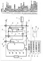
図13は、熱回収運転を機能として有する給湯装置であり、1は貯湯槽、2はヒートポンプユニット、3は浴槽、4は熱交換器、5aは貯湯槽水搬送ポンプ、5bは浴槽水搬送ポンプ、6は熱回収分岐管、7は三方弁、8は高温水供給管、9は低温水供給管、10は給湯管、11は混合弁、12は浴槽水循環配管、13は開閉弁、14は給水管、15は給湯分岐管、16は熱交戻り管である。浴槽水循環配管12は、浴槽3の往き管と戻り管とを環状に接続して構成され、回路上に熱交換器4および浴槽水搬送ポンプ5bを備える。
FIG. 13 shows a hot water supply apparatus having a heat recovery operation as a function. 1 is a hot water storage tank, 2 is a heat pump unit, 3 is a bathtub, 4 is a heat exchanger, 5a is a hot water tank water transport pump, and 5b is a bath water transport pump. , 6 is a heat recovery branch pipe, 7 is a three-way valve, 8 is a high temperature water supply pipe, 9 is a low temperature water supply pipe, 10 is a hot water supply pipe, 11 is a mixing valve, 12 is a bath water circulation pipe, 13 is an on-off valve, 14 is A water supply pipe, 15 is a hot water supply branch pipe, and 16 is a heat exchange return pipe. The bathtub
また、混合弁11は、高温水供給管8と低温水供給管9とを入口側に接続し、給湯管10を出口側に接続するように構成され、開閉弁13を介して浴槽水循環配管12と接続される。さらに浴槽内の水温を検知する浴槽水温検知手段17が、浴槽水循環配管12の途中に設けられている。
The mixing
この給湯装置が風呂自動運転を行う場合は、まず、貯湯槽1に貯えられた湯と給水管14から供給される水とを混合弁11で所望温度の湯に混合して浴槽3へ給湯する。浴槽3へ給湯した後は、一定時間だけ湯の温度を一定に保つために保温動作を行う。保温動作は、浴槽湯温が一定温度以下に降下した場合におこない、貯湯槽水搬送ポンプ5aと浴槽水搬送ポンプ5bとを運転して、熱交換器4において、貯湯槽1内の湯(例えば約80℃)により浴槽3内の湯(例えば約35℃)を加温する。
When this hot water supply apparatus performs bath automatic operation, first, hot water stored in the hot
また、浴槽3の水温が一定温度以下に降下しているかどうかを判断するために、浴槽水搬送ポンプ5bのみを運転させる浴槽水温検知動作を間欠的に行う。浴槽水温検知手段17により浴槽3の水温が一定温度以下に降下していることが検知された場合には保温動作を行い、降下していない場合にはそのまま待機する。一定時間が経過した後には風呂自動運転を自動で終了する。
Moreover, in order to judge whether the water temperature of the
次に、追い焚き運転を行う場合は、貯湯槽水搬送ポンプ5aと浴槽水搬送ポンプ5bとが運転を行って、熱交換器4において、貯湯槽1内の湯(例えば約80℃)が浴槽3内の湯(例えば約35℃)を加温する。その結果、浴槽3内の水温は上昇し、貯湯槽1内に湯として貯えられている熱量(蓄熱量)は減少する。
Next, when the reheating operation is performed, the hot water storage tank
最後に、熱回収運転を行う場合は、同様に貯湯槽水搬送ポンプ5aと浴槽水搬送ポンプ5bとが運転を行うが、熱交換器4において、貯湯槽1内の水(例えば約10℃)が浴槽3内の水(例えば約35℃)を冷却して熱を回収する。その結果、浴槽3内の水温は降下し、貯湯槽1内に湯として貯えられる熱量(蓄熱量)は増加するので、ヒートポンプユニット2により沸き上げる熱量を軽減することができる。
Finally, in the case of performing the heat recovery operation, the hot water tank
また、このような運転を制御する方式のひとつに、風呂自動運転を停止した後、熱回収運転を開始するまでの時間をあらかじめ設定し、この時間を満了すると熱回収運転を行うというものがある(例えば、特許文献2参照)。 In addition, as one of the methods for controlling such operation, there is a method of setting a time until the heat recovery operation is started after stopping the automatic bath operation, and performing the heat recovery operation when this time expires. (For example, refer to Patent Document 2).
図14は、特許文献2に記載された従来の給湯装置の制御ブロックを示すものである。
FIG. 14 shows a control block of a conventional hot water supply apparatus described in
運転制御手段18は、風呂自動運転検出部19が風呂自動運転の停止を検出した後、熱回収運転を開始させるまでの時間を測定するタイマ20を動作させ、あらかじめ設定された時間を満了すれば熱回収運転制御手段21に熱回収運転を開始させる。
The operation control means 18 operates the
しかしながら、前記従来の構成では、風呂自動運転停止後に使用者が入浴のため、浴槽内に湯水が張られた状態で、一定量の湯水を供給する足し湯運転をしている時に、熱回収運転を開始する場合があり、浴槽の水温が低下してしまって入浴できなくなるという課題を有していた。 However, in the above-described conventional configuration, the heat recovery operation is performed when an additional hot water operation for supplying a certain amount of hot water is performed in a state where hot water is stretched in the bathtub for the user to take a bath after the automatic bath operation is stopped. There was a problem that the temperature of the water in the bathtub was lowered and bathing became impossible.
本発明は、前記従来の課題を解決するもので、使用者が入浴のため足し湯運転している際に、熱回収運転によって浴槽の水温が低下することを防止した給湯装置を提供することを目的とする。 The present invention solves the above-described conventional problems, and provides a hot water supply apparatus that prevents a water temperature of a bathtub from being lowered by a heat recovery operation when a user is performing a hot water operation for bathing. Objective.
前記従来の課題を解決するために、本発明の給湯装置は、貯湯槽と、浴槽と、前記貯湯槽内の湯水と前記浴槽内の湯水とを熱交換する熱交換器と、制御手段とを備え、前記浴槽に湯水を供給する足し湯運転モードと、前記熱交換器により前記浴槽の湯水の有する熱を前記貯湯槽の湯水に回収する熱回収運転モードとを有し、熱回収運転よりも足し湯運転を優先させることを特徴とするもので、足し湯運転中である場合には熱回収運転をせず、熱回収機能によって浴槽の水温が低下して入浴ができなくなることを防止できる。 In order to solve the conventional problems, a hot water supply apparatus of the present invention includes a hot water storage tank, a bathtub, a heat exchanger that exchanges heat between the hot water in the hot water tank and the hot water in the bathtub, and a control unit. An additional hot water operation mode for supplying hot water to the bathtub, and a heat recovery operation mode for recovering the heat of the hot water in the bathtub to the hot water in the hot water tank by the heat exchanger, rather than the heat recovery operation It is characterized by giving priority to additional hot water operation. When the hot water operation is in progress, heat recovery operation is not performed, and it is possible to prevent the bath water temperature from being lowered due to the heat recovery function and preventing bathing.
本発明によれば、使用者が入浴のため足し湯運転している際に、熱回収運転によって浴槽の水温が低下することを防止した給湯装置を提供できる。 ADVANTAGE OF THE INVENTION According to this invention, when a user is performing additional hot water operation for bathing, the hot water supply apparatus which prevented the water temperature of the bathtub from falling by heat recovery operation can be provided.
第1の発明は、貯湯槽と、浴槽と、前記貯湯槽内の湯水と前記浴槽内の湯水とを熱交換する熱交換器と、制御手段とを備え、前記浴槽に湯水を供給する足し湯運転モードと、前記熱交換器により前記浴槽の湯水の有する熱を前記貯湯槽の湯水に回収する熱回収運転モードとを有し、熱回収運転よりも足し湯運転を優先させることを特徴とする給湯装置で、足し湯運転中である場合には熱回収運転をせず、熱回収機能によって浴槽内の湯温が低下して入浴ができなくなることを防止できる。 The first invention includes a hot water tank, a bathtub, a heat exchanger for exchanging heat between the hot water in the hot water tank and the hot water in the bathtub, and a control means, and an additional hot water that supplies hot water to the bathtub It has an operation mode and a heat recovery operation mode in which the heat of the hot water in the bathtub is recovered in the hot water of the hot water tank by the heat exchanger, and the hot water operation has priority over the heat recovery operation. In the hot water supply device, when the hot water is being operated, the heat recovery operation is not performed, and the heat recovery function can prevent the hot water temperature in the bathtub from being lowered and preventing bathing.
第2の発明は、前記熱回収運転中に前記足し湯運転を行う場合には、前記熱回収運転を停止することを特徴とするもので、熱回収運転中に入浴する使用者があった場合に、即座に熱回収運転を停止することにより、浴槽内の湯温が低下して入浴ができなくなることを防止できる。 The second invention is characterized in that when the additional hot water operation is performed during the heat recovery operation, the heat recovery operation is stopped, and there is a user who takes a bath during the heat recovery operation. In addition, by immediately stopping the heat recovery operation, it is possible to prevent the temperature of the hot water in the bathtub from lowering and preventing bathing.
第3の発明は、前記足し湯運転中で前記熱回収運転を開始しなかった場合、前記足し湯運転終了後に前記熱回収運転を開始することを特徴とするもので、熱回収運転が開始できなかった場合に、使用者の入浴が終われば熱回収運転を改めて開始することにより、省エネルギー性を損なわない運転ができる。 According to a third aspect of the present invention, when the heat recovery operation is not started during the addition hot water operation, the heat recovery operation is started after the addition hot water operation is completed, and the heat recovery operation can be started. If the user has not taken a bath, the heat recovery operation is started again when the user finishes bathing, so that the operation without impairing the energy saving performance can be performed.
第4の発明は、前記熱回収運転中に前記足し湯運転を行うために前記熱回収運転を停止した場合、前記足し湯運転終了後に前記熱回収運転を再開することを特徴とするもので、熱回収運転を停止した場合に、使用者の入浴が終われば熱回収運転を改めて再開することにより、省エネルギー性を損なわない運転ができる。 The fourth invention is characterized in that when the heat recovery operation is stopped in order to perform the addition hot water operation during the heat recovery operation, the heat recovery operation is restarted after the addition hot water operation ends. When the heat recovery operation is stopped, when the user's bathing is completed, the heat recovery operation is restarted again so that the operation without impairing the energy saving performance can be performed.
第5の発明は、前記貯湯槽内の湯水を加熱する加熱手段を備え、前記熱回収運転停止後の前記加熱手段の加熱運転時における入力が略最小となるように、前記熱回収運転を停止させることを特徴とするものである。 5th invention is equipped with the heating means which heats the hot water in the said hot water tank, and stops the said heat recovery operation so that the input at the time of the heating operation of the said heating means after the said heat recovery operation stop becomes substantially the minimum It is characterized by making it.
これにより、熱回収運転中の貯湯槽の温度分布に基づき、加熱手段によって所定の貯湯量を沸き上げるための消費熱量(消費電力)が最小となる時点を判断して、熱回収運転を停止するので、本来の目的であるシステム全体としての効率向上を実現し、省エネルギー性を高める効果がある。 Thus, based on the temperature distribution of the hot water storage tank during the heat recovery operation, the time point at which the heat consumption (power consumption) for boiling up the predetermined hot water storage amount by the heating means is judged to be minimum, and the heat recovery operation is stopped. Therefore, it is possible to improve the efficiency of the entire system, which is the original purpose, and to improve energy saving.
第6の発明は、前記貯湯槽の水温を検知する複数の貯湯温検知手段を備え、前記複数の貯湯温検知手段のうち少なくともひとつの検知温度に基づいて、前記熱回収運転を停止させることを特徴とするもので、熱回収運転を行う際に、熱回収運転の運転停止を最適化することにより、システム効率を向上させ省エネルギー性を高めた給湯装置を提供できる。 6th invention is provided with the some hot water storage temperature detection means which detects the water temperature of the said hot water storage tank, and stops the said heat | fever collection | recovery driving | operation based on at least 1 detection temperature among these hot water storage temperature detection means. In the heat recovery operation, by optimizing the stop of the heat recovery operation, it is possible to provide a hot water supply device with improved system efficiency and energy saving.
第7の発明は、使用者が、前記熱回収運転を起動するための熱回収運転起動スイッチを設けたことを特徴とするもので、自動で設定されるなどした熱回収運転の起動スケジュールによらず、以降の入浴が発生しないと使用者が判断した時点で熱回収運転を始めることができるので、浴槽からの無駄な放熱が抑えられて省エネルギー性が高まるという効果がある。 The seventh invention is characterized in that a user is provided with a heat recovery operation start switch for starting the heat recovery operation, and according to a heat recovery operation start schedule set automatically or the like. In addition, since the heat recovery operation can be started when the user determines that subsequent bathing does not occur, there is an effect that wasteful heat dissipation from the bathtub is suppressed and energy saving is improved.
第8の発明は、前記貯湯槽に接続された給水管と、前記貯湯槽の高温水を供給するように接続された高温水供給管と、低温水を供給するように、前記貯湯槽下部または前記給水管に接続された低温水供給管と、入口側に前記高温水供給管と前記低温水供給管とを接続して前記高温水と前記低温水とを混合する混合弁と、前記熱交換器と前記浴槽内の湯水が
循環するように接続された浴槽循環配管と、前記浴槽へ所定の温度の湯水を供給するように前記混合弁の出口側と前記浴槽循環配管とに接続された給湯管と、前記給湯管の途中に接続された開閉弁と、前記開閉弁の上流で分岐して前記熱交換器に接続された給湯分岐管と、前記熱交換器で前記浴槽の湯水と熱交換した前記貯湯槽の湯水を再び前記貯湯槽へ戻すように前記熱交換器と前記貯湯槽とに接続された熱交戻り管と、前記貯湯槽と前記熱交換器で湯水を循環させる第1の搬送ポンプと、前記浴槽と前記熱交換器で湯水を循環させる第2の搬送ポンプとを備え、前記開閉弁を閉じ、前記混合弁を前記高温水供給管からの湯水よりも前記低温水供給管からの水を優先して給湯管へ供給する開度に調整し、かつ、前記第1の搬送ポンプと前記第2の搬送ポンプを動作させ、前記熱回収運転を行うことを特徴とするものである。
The eighth invention comprises a water supply pipe connected to the hot water storage tank, a high temperature water supply pipe connected to supply high temperature water in the hot water storage tank, and a lower part of the hot water storage tank to supply low temperature water. A low-temperature water supply pipe connected to the water supply pipe; a mixing valve for connecting the high-temperature water supply pipe and the low-temperature water supply pipe to the inlet side to mix the high-temperature water and the low-temperature water; and the heat exchange A hot water supply connected to the outlet side of the mixing valve and the bathtub circulation pipe so as to supply hot water of a predetermined temperature to the bathtub. A pipe, an on-off valve connected in the middle of the hot water supply pipe, a hot water branch pipe branched upstream of the on-off valve and connected to the heat exchanger, and heat exchange with hot water in the bathtub in the heat exchanger The heat exchanger and the storage so that the hot water in the hot water storage tank is returned to the hot water storage tank again. A heat exchange return pipe connected to the tank, a first transfer pump for circulating hot water in the hot water storage tank and the heat exchanger, and a second transfer pump for circulating hot water in the bathtub and the heat exchanger; The open / close valve is closed, the mixing valve is adjusted to an opening degree for supplying water from the low temperature water supply pipe to the hot water pipe with priority over hot water from the high temperature water supply pipe, and the first One transport pump and the second transport pump are operated to perform the heat recovery operation.
これにより、給湯と追い焚きと熱回収の3つの機能を最小限の配管や弁の構成で実現することができ、前記貯湯槽の筐体内設置空間の省スペース化とそれによる装置の小型化を図ることができる。また、給湯と追い焚きと熱回収の3つの機能を、前記混合弁の開度の制御によって実現できるので、制御が簡素化されて誤動作などの不具合が減少するという効果がある。 As a result, the three functions of hot water supply, reheating, and heat recovery can be realized with the minimum configuration of piping and valves, and the installation space in the casing of the hot water tank can be saved and the apparatus can be downsized. Can be planned. In addition, since the three functions of hot water supply, chasing, and heat recovery can be realized by controlling the opening of the mixing valve, there is an effect that the control is simplified and malfunctions such as malfunctions are reduced.
第9の発明は、前記高温水供給管と連通し、前記貯湯槽の略上部に接続された第1の出湯管と、前記貯湯槽の上下方向において前記第1の出湯管が接続された位置と前記給水管が接続された位置との間に接続された第2の出湯管とを備え、前記熱交戻り管は、前記貯湯槽の上下方向において、前記第2の出湯管の前記貯湯槽の接続位置よりも高い位置で、前記貯湯槽に接続されていることを特徴とするものである。 9th invention is the position where the said 1st tap pipe was connected in the up-down direction of the said hot water storage tank, and the 1st hot water pipe connected to the said hot water supply pipe and connected to the substantially upper part of the said hot water storage tank And a second hot water discharge pipe connected between the water supply pipe and the position where the water supply pipe is connected, and the heat exchange return pipe is located in the vertical direction of the hot water storage tank and the hot water storage tank of the second hot water discharge pipe. It is characterized by being connected to the hot water storage tank at a position higher than the connection position.
これにより、温度成層型の貯湯槽において不可避な貯湯槽上部の高温水と下部の低温水との間にできる中間程度の温度の水(以下、中温水)を有効に利用できる結果として、同じ蓄熱量でも貯湯槽下方に低温の水が多く確保できることから浴槽水からの回収熱量を大きくできる。 As a result, it is possible to effectively use water at a medium temperature (hereinafter referred to as medium hot water) between the hot water at the upper part of the hot water tank and the cold water at the lower part, which is unavoidable in the temperature stratified hot water tank. The amount of heat recovered from the bath water can be increased because a large amount of low-temperature water can be secured below the hot water tank.
また、熱回収により発生した中温水を貯湯槽の比較的上部に流入させることは、増加しながら貯湯槽下方に移動する中温水を、熱回収した湯の流入位置よりも下にある第2の出湯管を通じて給湯に利用できるので、貯湯された湯の熱量を最大限有効に使うことができる。同時に加熱手段がヒートポンプユニットである場合には、沸き上げ効率の低下を招く貯湯槽内の中温水が減少することでシステム全体の効率低下を防ぐことができ、熱量の有効利用による良好な使い勝手と高い省エネルギー性とを実現する。 In addition, flowing the warm water generated by the heat recovery into the relatively upper part of the hot water tank means that the hot water that moves below the hot water tank while increasing the temperature of the hot water that is below the inflow position of the hot water recovered. Since it can be used for hot water supply through the hot water outlet, the amount of heat stored in the hot water can be used to the maximum extent possible. At the same time, when the heating means is a heat pump unit, the medium temperature water in the hot water tank that reduces the boiling efficiency can be reduced, so that the efficiency of the entire system can be prevented from being reduced. Realize high energy savings.
さらに、通常、熱回収運転される時間帯は深夜であるが、熱回収運転中に使用者の入浴を検出した場合を想定すると、その時点から浴槽水の追い焚き運転が必要となる。このとき、それ以前の給湯の際に中温水を有効に利用し、深夜になっても貯湯槽の上部の水は比較的高温に保たれて残っているので、追い焚き性能を確保できるという効果があるとともに、中温水が貯湯槽の比較的上部に戻されることで貯湯槽下部の水温の上昇は小さいので、使用者の入浴完了後に熱回収運転を再開した場合にヒートポンプユニットへの流入水温が低く保たれて効率的な運転がなされ、省エネルギー性を損なわない。 Furthermore, normally, the time period during which the heat recovery operation is performed is midnight, but assuming a case where a user's bathing is detected during the heat recovery operation, a bath water reheating operation is required from that point. At this time, the middle temperature water is effectively used at the time of hot water supply before that, and the water in the upper part of the hot water tank remains relatively high even at midnight, so that the reheating performance can be secured. In addition, the rise in the water temperature at the bottom of the hot water tank is small because the medium temperature water is returned to the relatively upper part of the hot water tank, so when the heat recovery operation is resumed after the user completes bathing, the temperature of the water flowing into the heat pump unit Efficient operation is performed while being kept low, and energy efficiency is not impaired.
以下、本発明の実施の形態について、図面を参照しながら説明する。なお、この実施の形態によって本発明が限定されるものではない。 Hereinafter, embodiments of the present invention will be described with reference to the drawings. Note that the present invention is not limited to the embodiments.
(実施の形態1)
図1は本発明の実施の形態1における給湯装置の構成を示す図である。
(Embodiment 1)
FIG. 1 is a diagram showing a configuration of a hot water supply apparatus according to
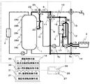
図1において、給湯装置は、貯湯槽1と、この貯湯槽1の水を加熱する加熱手段として
のヒートポンプユニット2と、熱回収を行う対象の浴槽3と、浴槽3の水と貯湯槽1の水とを熱交換するように構成された熱交換器4と、貯湯槽1に接続された給水管14と、貯湯槽1の略上部に接続された第1の出湯管22と、第1の出湯管22と給水管14とが接続された位置の間、すなわち、高さ方向において貯湯槽1の胴部略中央部に接続された第2の出湯管23と、第1の出湯管22と第2の出湯管23とが入口側に接続された高温水混合弁24と、この高温水混合弁24の出口側に接続され、貯湯槽1内の高温水を供給する高温水供給管8と、給水管14から分岐され、貯湯槽1内または給水管14からの低温水を供給する低温水供給管9と、これら高温水供給管8と低温水供給管9とを入口側に接続された混合弁11とを備えている。
In FIG. 1, a hot water supply apparatus includes a
また、この混合弁11の出口側に接続された給湯管10と、給湯管10の途中に接続された開閉弁13と、開閉弁13の上流で分岐して熱交換器4の第1の流路に接続された給湯分岐管15と、熱交換器4で浴槽3の水と熱交換した貯湯槽1の水を再び貯湯槽1へ戻すように熱交換器4の第1の流路と貯湯槽1とに接続された熱交戻り管16と、貯湯槽1と熱交換器4の第1の流路内の水を循環させる第1の搬送ポンプとしての貯湯槽水搬送ポンプ5aと、熱交換器4の第2の流路内へ浴槽3の水が循環するように接続された浴槽水循環配管12と、浴槽3と熱交換器4の第2の流路内の水を循環させる第2の搬送ポンプとしての浴槽水搬送ポンプ5bとを備えている。
Further, a
ここで熱交戻り管16は、貯湯槽1の上下方向において第1の出湯管22と第2の出湯管23の間の位置で貯湯槽1に接続される。また、給湯管10は、浴槽水循環配管12の途中に接続し、浴槽3への給湯の際はこの浴槽水循環配管12を利用する。
Here, the heat
また、浴室内に設置されたリモコン25には、人体検知手段としての赤外線センサ26と、使用者が任意に熱回収運転を起動するための熱回収運転起動スイッチ27を設け、貯湯槽1には、貯湯槽1内の水温を検知するための複数の貯湯温検知手段28a〜28e、浴槽水循環配管12には、浴槽3の水温を検知するための浴槽水温検知手段17を設けている。
The
さらに、これら複数の貯湯温検知手段28a〜28eと赤外線センサ26と浴槽水温検知手段17の出力および熱回収運転起動スイッチ27の操作に基づいて、浴槽3への給湯およびそれ以降あらかじめ設定された時間だけ浴槽水の保温と水量維持を行う風呂自動運転を制御する給湯制御手段としての風呂自動運転制御手段29と、浴槽3内の水を加熱する追い焚き運転を制御する追い焚き運転制御手段30と、浴槽3内に湯水が張られた状態で、比較的少量(たとえば10L)の湯水を浴槽3に供給する足し湯運転を制御する足し湯運転制御手段31と、貯湯槽1に浴槽3の水の熱を回収する熱回収運転を制御する熱回収運転制御手段21とからなる運転制御手段18を設けている。
Further, based on the outputs of the plurality of hot water storage temperature detection means 28a to 28e, the
図2は熱回収運転制御手段21のブロック図を示し、赤外線センサ26の出力および風呂自動運転制御手段29の動作状態あるいは熱回収運転制御手段21であらかじめ設定された熱回収運転の開始時刻、さらには熱回収運転起動スイッチ27などから熱回収運転の開始を判断する熱回収運転開始判断部32と、ヒートポンプユニット2による沸上運転を制御する沸上運転制御手段(図示せず)から貯湯後の給湯利用に必要な貯湯熱量を取得する所要貯湯熱量取得部33と、貯湯温検知手段28a〜28eにより貯湯温度分布を測定する貯湯温度分布測定部34と、これら所要貯湯熱量取得部33と貯湯温度分布測定部34で得られた結果に基づいて必要な沸上熱量を算出する必要沸上熱量算出部35と、貯湯温度分布測定部34による現在の温度分布と必要沸上熱量算出部35から沸上完了時の温度分布を推定する沸上完了時貯湯温度分布推定部36とを有している。
FIG. 2 shows a block diagram of the heat recovery operation control means 21, the output of the
さらに貯湯温度分布測定部34による現在の温度分布から沸上完了時貯湯温度分布推定
部36での沸き上げ完了時の推定温度分布に至る間のヒートポンプユニット2への入力を推定する沸上所要入力推定部37と、この沸上所要入力推定部37による入力推定値の時間変化に基づいて貯湯槽水搬送ポンプ5a、浴槽水搬送ポンプ5bとを制御するポンプ制御部37とを有している。
Further, the boiling required input for estimating the input to the
以上のように構成された給湯装置について、以下その動作、作用を説明する。 About the hot water supply apparatus comprised as mentioned above, the operation | movement and an effect | action are demonstrated below.
一般的な家庭での湯の利用における基本的な動作として、朝には貯湯槽1にその日使う分の湯が貯えられており、活動している時間帯に順次給湯に利用される。給湯利用中に貯湯量が不足する場合には必要に応じてヒートポンプユニット2を運転し、追加で貯湯運転を行うこともある。近年では、浴槽3への給湯から保温までを自動で行う風呂自動運転の機能を備えている給湯装置が多くなっている。
As a basic operation in the use of hot water in a general home, hot water for the day is stored in the
風呂自動運転制御手段29により浴槽3への給湯および保温運転を行う場合は、貯湯槽1内に貯えられている湯を用いて浴槽3へ給湯し、浴槽水温が低下した場合には、貯湯槽1内に貯えられている湯の熱を利用して保温運転をおこない、浴槽水温を予め設定された温度に保つ。また、追い焚き運転制御手段30により追い焚き運転を行って浴槽3内の湯を加温する場合も、貯湯槽1内に貯えられている湯の熱を利用して行う。
When the bath automatic operation control means 29 performs hot water supply to the
これら一日の給湯などの熱利用が終わる時点で貯湯槽1内の湯は大部分が給水と置換され、その後の深夜に再び次の利用のための貯湯運転がおこなわれる。このとき、入浴のために浴槽3に供給された湯は、給湯利用終了時には貯湯槽1内の水温に対して比較的高温で残されていることが多いので、熱回収運転制御手段21が、ヒートポンプユニット2による深夜の沸上運転の前、あるいは運転中に熱回収運転を行って貯湯槽1内に熱を回収する。
Most of the hot water in the hot
次に、風呂自動運転、追い焚き運転、足し湯運転、および熱回収運転の制御方法について説明する。 Next, control methods for bath automatic operation, reheating operation, additional hot water operation, and heat recovery operation will be described.
風呂自動運転制御手段29は、浴槽3へ所定量の湯を所定温度で自動で給湯し、その後、浴槽水温を予め設定された時間だけ予め設定された温度に保つように間欠的に保温動作を行う(風呂自動運転)。風呂自動運転を行っている間は、保温動作を行う必要があるかないかを判断するために、定期的に浴槽湯温を検出するための浴槽湯温検知動作を行う。
The bath automatic operation control means 29 automatically supplies a predetermined amount of hot water to the
浴槽水温の検知は浴槽水温検知手段17でおこない、その結果、浴槽水温が予め設定された温度より所定温度以上(例えば1K以上)低い場合には、保温運転を行って浴槽水温を保ち、所定温度未満の場合には、保温運転をおこなわない。
The bath water temperature is detected by the bath water
この予め設定された時間内は、風呂自動運転を優先とし、熱回収運転制御手段21が自動で、あるいは使用者による熱回収運転起動スイッチ27の操作で熱回収運転開始の指示を受けても熱回収運転を行わず、予め設定された時間が経過した後に、熱回収運転を行うように制御する。
During this preset time, automatic bath operation is prioritized, and the heat recovery operation control means 21 is automatically operated or the heat recovery operation start
逆に、熱回収運転中に風呂自動運転制御手段29が風呂自動運転開始の指示を受けた場合には、風呂自動運転を優先として、熱回収運転制御手段21は熱回収運転を停止し、風呂自動運転制御手段29が風呂自動運転を開始する(図3に概念図を示す)。 On the contrary, when the bath automatic operation control means 29 receives an instruction to start the bath automatic operation during the heat recovery operation, the heat recovery operation control means 21 stops the heat recovery operation, giving priority to the bath automatic operation. The automatic operation control means 29 starts bath automatic operation (conceptual diagram is shown in FIG. 3).
追い焚き運転制御手段30は、浴槽3内の湯を循環加温し、浴槽水温検知手段17が検知する浴槽水温が所定の温度になる、または動作開始から所定の時間経過すると終了する(追い焚き運転)。追い焚き運転制御手段30が追い焚き運転を行っている間は、追い焚
き運転を優先とし、熱回収運転制御手段21は熱回収運転をおこなわず、追い焚き運転が終了した後に、熱回収運転を行うように制御する。
The reheating operation control means 30 circulates and warms the hot water in the
逆に、熱回収運転中に追い焚き運転制御手段30が追い焚き運転の指示を受けた場合にも、追い焚き運転を優先として、熱回収運転制御手段21は熱回収運転を停止し、追い焚き運転制御手段30が追い焚き運転を開始する(図4に概念図を示す)。 Conversely, even when the reheating operation control means 30 receives an instruction for reheating operation during the heat recovery operation, the recuperation operation is given priority, and the heat recovery operation control means 21 stops the heat recovery operation and retreats. The operation control means 30 starts a chasing operation (a conceptual diagram is shown in FIG. 4).
足し湯運転制御手段31は、浴槽3内に湯水が張られた状態で、比較的少量(たとえば10L)の湯水を浴槽3に所定温度で自動で供給する(足し湯運転)。足し湯運転制御手段31が足し湯運転を行っている間は、足し湯運転を優先とし、熱回収運転制御手段21は熱回収運転をおこなわず、足し湯運転が終了した後に、熱回収運転を行うように制御する。
The additional hot water operation control means 31 automatically supplies a relatively small amount (for example, 10 L) of hot water to the
逆に、熱回収運転中に足し湯運転制御手段31が足し湯運転の指示を受けた場合にも、足し湯運転を優先として、熱回収運転制御手段21は熱回収運転を停止し、足し湯運転制御手段31が足し湯運転を開始する。 Conversely, when the additional hot water operation control means 31 receives an instruction for the additional hot water operation during the heat recovery operation, the heat recovery operation control means 21 stops the heat recovery operation with priority given to the additional hot water operation, and the additional hot water operation. The operation control means 31 starts adding hot water operation.
各々の運転を行う場合の弁およびポンプの動作と、それに伴う水および湯の流れについて図5〜図8を用いて説明する。図中、流れのある経路は太線で示してある。 The operation of the valve and the pump when performing each operation and the flow of water and hot water associated therewith will be described with reference to FIGS. In the figure, the flow path is indicated by a bold line.
まず、風呂自動運転制御手段29が風呂自動運転を行うときの動作について説明する。 First, the operation when the bath automatic operation control means 29 performs bath automatic operation will be described.
最初に浴槽3へ給湯を行う場合における回路中の水および湯の流れを図5に示す。貯湯槽1からは、第1の出湯管22と第2の出湯管23からの湯を高温水混合弁24で混合して高温水供給管8へ供給する。この高温水供給管8に供給された湯と給水管14から低温水供給管9へと供給される給水とが混合弁11にて給湯所望温度の湯に混合され、給湯管10へと供給される。
FIG. 5 shows the flow of water and hot water in the circuit when hot water is first supplied to the
ここで、高温水混合弁24から高温水供給管8に供給される湯の温度は、上記の給湯所望温度よりも所定温度以上高い温度(たとえば給湯所望温度が40℃の場合に45℃以上)に調節されている。開閉弁13は開かれ、給湯管10へと供給された所望温度の湯は、浴槽水循環配管12より浴槽3へと給湯される。
Here, the temperature of the hot water supplied from the high-temperature
なお、高温水混合弁24と混合弁11の開度は、それぞれ出口側に接続された高温水供給管8と給湯管10に供給される湯の温度に基づいてフィードバック制御されるのが一般的であり、高温水混合弁24については第1の出湯管22と第2の出湯管からの湯、混合弁11については高温水供給管8からの湯と低温水供給管9からの給水の温度により変化する。
The opening degree of the high temperature
浴槽3内の湯を保温する場合における回路中の水および湯の流れを図6に示す。貯湯槽水搬送ポンプ5aと浴槽水搬送ポンプ5bとが運転を開始し、貯湯槽水搬送ポンプ5aの運転により、貯湯槽1の略上部より第1の出湯管22から高温水混合弁24を経て高温水供給管8へと湯が供給され、さらに混合弁11を経て給湯管10へと供給される。
FIG. 6 shows the flow of water and hot water in the circuit when the hot water in the
このとき、開閉弁13を閉じ、給湯管10へと供給された湯は、給湯分岐管15へと供給され、熱交換器4にて浴槽水循環配管12を循環する浴槽3の湯を加熱して、浴槽水温を上昇させる。一方、熱交換器4を出て比較的低温となった湯は熱交戻り管16を経て貯湯槽1へと還流する。
At this time, the on-off
このとき、高温水混合弁24と混合弁11の開度は、それぞれ第1の出湯管22と高温
水供給管8側が全開となり、貯湯槽1上部の高温の湯が熱交換器4に供給されるように制御されるのが一般的であるが、第2の出湯管23と低温水供給管9より一定量の湯または水が流入して混合するものであってもよい。
At this time, the opening degree of the high temperature
浴槽3内の水温を検知するための浴槽水温検知動作を行う場合における回路中の水および湯の流れを図7に示す。浴槽水搬送ポンプ5bが運転を開始し、浴槽水循環配管12内を浴槽3内の湯が循環する。このとき、開閉弁13を閉じ、貯湯槽水搬送ポンプ5aは運転をおこなわない。浴槽水温検知手段17が浴槽水温を検知し、保温動作をするかしないかを判断する。
FIG. 7 shows the flow of water and hot water in the circuit when the bathtub water temperature detection operation for detecting the water temperature in the
次に、追い焚き運転制御手段30が追い焚き運転を行う場合の動作であるが、追い焚き運転を行う場合における回路中の水および湯の流れは風呂自動運転制御手段29が保温動作を行う場合と同じで図6に示す通りであるので省略する。 Next, the operation when the reheating operation control means 30 performs the reheating operation, the flow of water and hot water in the circuit when the reheating operation is performed, when the bath automatic operation control means 29 performs the heat retaining operation. Since this is the same as shown in FIG.
次に、足し湯運転制御手段31が足し湯運転を行う場合の動作であるが、足し湯運転を行う場合における回路中の水および湯の流れは風呂自動運転制御手段29が浴槽3へ給湯を行う場合と同じで図5に示す通りであるので省略する。
Next, the operation when the additional hot water operation control means 31 performs the additional hot water operation. The flow of water and hot water in the circuit when the additional hot water operation is performed is determined by the automatic bath operation control means 29 for supplying hot water to the
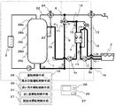
最後に、熱回収運転制御手段21が、浴槽3に残された湯の熱回収運転を行う場合における回路中の水および湯の流れを図8に示す。熱回収運転を開始すると、貯湯槽水搬送ポンプ5aの運転により、貯湯槽1の略下部より低温水供給管9へと水が供給され、混合弁11を経て給湯管10へと供給される。
Finally, FIG. 8 shows the flow of water and hot water in the circuit when the heat recovery operation control means 21 performs the heat recovery operation of the hot water remaining in the
このとき、開閉弁13を閉じ、給湯管10へと供給された水は、給湯分岐管15へと供給され、熱交換器4にて浴槽水循環配管12を循環する浴槽3の湯と熱交換を行って熱を回収する。一方、熱交換器4を出て比較的高温となった水は熱交戻り管16を経て貯湯槽1へと還流する。このとき、混合弁11の開度は、低温水供給管9側が全開となるように制御されるのが一般的であるが、高温水供給管8より一定量の湯が流入し混合するものであってもよい。
At this time, the on-off
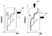
熱回収運転を行った場合の貯湯槽1内の温度分布は図9に示す39、40、41の順に変化する。つまり、浴槽3と熱交換されて熱交戻り管16から貯湯槽1に流入する水42の温度は貯湯槽1の貯湯温よりも低い場合が多く、貯湯槽水搬送ポンプ5aの作用によって貯湯槽1の湯と混合しつつ貯湯槽1の下方に向けて移動する。
When the heat recovery operation is performed, the temperature distribution in the
第2の出湯管23の接続位置は熱交戻り管16の接続位置よりも下部にあるので、給湯が発生すると、下がってきた中温の水43を第2の出湯管23から出湯し、第1の出湯管からの高温水44と混合して利用することができる。
Since the connection position of the second hot
図9に示す45は、熱回収後に給湯が発生した場合の温度分布を示している。このように第2の出湯管23が熱交戻り管16の貯湯槽への接続位置よりも下にあることで、回収した熱を効果的に利用することができる。
給湯の発生が比較的少なく、使い切れないで残った中温の水は、ヒートポンプユニット2で再加熱して利用することになるが、ヒートポンプユニット2の運転効率は、図10に示すように加熱前の水温が高いほど低下する。
The occurrence of hot water supply is relatively small, and the medium-temperature water that remains without being used up is reheated and used by the
図9に示した貯湯槽1の温度分布からわかるように、熱回収運転後のヒートポンプユニット2による必要加熱量は、浴槽3からの回収熱量が増加するほど少なくなるものの、それと同時にヒートポンプユニット2で加熱する前の水温は高くなって、再加熱時の運転効
率は低下するので、できるだけ多くの熱回収を行うことが必ずしも省エネルギーにつながらない。
As can be seen from the temperature distribution of the
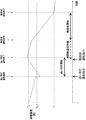
すなわち、ヒートポンプユニット2への入力(消費熱量あるいは消費電力)は、所要貯湯熱量を得るための熱回収前の必要加熱量から熱回収運転によって得られた回収熱量を減じたものを、ヒートポンプユニット2による貯湯運転中の平均効率で除したものとなり、この値は図11に示すように、回収熱量に対して最小値を有する場合がある。
That is, the input (heat consumption or power consumption) to the
したがって、浴槽3からの熱回収運転を、熱回収運転停止後に行われる再加熱運転において、ヒートポンプユニット2への入力が略最小となる時点で停止することが、より高い省エネルギー効果を得るために必要である。
Therefore, in order to obtain a higher energy saving effect, it is necessary to stop the heat recovery operation from the
最小値となる時点を見つける具体的な方法としては、所定の時間間隔で測定される貯湯槽1の温度分布に基づいて予想されるヒートポンプユニット2への入力値の刻々の変化の推移を求めて、その値の減少度合いが小さいか減少しなくなる、あるいは増加に転じることで判断する。
As a specific method for finding the time point at which the minimum value is reached, the change of the input value to the
図10に示したように、貯湯槽1内の湯水をヒートポンプユニット2にて加熱する場合、貯湯槽1からヒートポンプユニット2に水を搬送させる部位の温度(本実施の形態においては、貯湯槽1の下部の温度)が低くなるにつれて、ヒートポンプユニット2の運転効率は高くなるが、浴槽3からの熱回収運転時、浴槽3から熱回収した水が貯湯槽1内に流入してくることで、貯湯槽1からヒートポンプユニット2に水を搬送させる部位の温度が上昇し始める状態が存在する。
As shown in FIG. 10, when the hot water in the
したがって、浴槽3からの熱回収運転時に、貯湯槽1のヒートポンプユニット2に水を搬送させる部位の温度を測定し、その温度の上昇度合いが増加に転じる付近で、浴槽3からの熱回収運転動作を停止させることで、熱回収運転後の加熱運転時におけるヒートポンプユニット2の運転効率の略最大を実現できるのである。
Therefore, at the time of the heat recovery operation from the
上記を勘案して高い省エネルギー効果を得るための熱回収運転制御手段21の制御方法について説明する。 A control method of the heat recovery operation control means 21 for obtaining a high energy saving effect in consideration of the above will be described.
図12は熱回収運転制御手段21の動作のフローチャートである。使用者による熱回収運転起動スイッチ27の操作、あるいは風呂自動運転制御手段29による風呂自動運転終了後の所定時間経過後など、熱回収運転の開始を熱回収運転開始判断部32が判断すると、最初に赤外線センサ26によって入浴者の有無を検知し(ステップ1)、ここで入浴者が検知された場合は、熱回収運転を開始しないで終了する(ステップ2)。
FIG. 12 is a flowchart of the operation of the heat recovery operation control means 21. When the heat recovery operation start
ステップ1で入浴者を検知しなければ、所要貯湯熱量取得部33で取得された所要貯湯熱量と貯湯温検知手段28a〜28eにより測定された現在の貯湯槽1の温度分布、およびヒートポンプユニット2の沸き上げ温度等の運転条件から貯湯運転完了時の貯湯槽1内の温度分布を予測し、それを現在の温度分布と比較して、その時点からヒートポンプユニット2で加熱する場合の残りの加熱量Qrを求める(ステップ3)。
If no bather is detected in
次に、測定された現在の温度分布から、予測された貯湯運転完了時の温度分布に達するまでの間にヒートポンプユニット2で沸き上げる前の平均水温を推定する(ステップ4)。
Next, the average water temperature before boiling in the
さらにステップ4で求めた平均水温と図4で示したヒートポンプユニット2の特性とから貯湯運転時の平均効率を求め、ステップ3で求めた残りの加熱量Qrをこの平均効率で
除して、貯湯運転時の入力Qinを推定する(ステップ5)。
Further, the average efficiency during hot water storage operation is obtained from the average water temperature obtained in step 4 and the characteristics of the
Qinは前回の評価時刻において求めた値であるQin−fとの差を求め、それがあらかじめ定めた偏差qより小さい場合、すなわち推定入力の変化が次第に小さくなって最小値と判断されたら(ステップ6)、ステップ2で貯湯槽水搬送ポンプ5aと浴槽水搬送ポンプ5bとを停止して熱回収運転を終了する。
Qin obtains a difference from Qin−f which is a value obtained at the previous evaluation time, and when it is smaller than a predetermined deviation q, that is, when a change in estimated input gradually becomes smaller and it is determined to be a minimum value (step) 6) In
QinとQin−fとの差がq以上の場合は熱回収運転を継続し、次の評価時刻になれば(ステップ8)、以上の動作を繰り返す。 When the difference between Qin and Qin−f is equal to or greater than q, the heat recovery operation is continued, and when the next evaluation time comes (step 8), the above operation is repeated.
なお、補足として熱回収運転開始後一回目の動作時は、ステップ6での比較はおこなわずにステップ7を実行する。
As a supplement,
ここでは熱回収運転の開始時に入浴者を検知した場合を説明したが、ステップ1では熱回収運転が開始された後で入浴者が検知された場合にも、熱回収運転は停止されることになる(ステップ2)。
Here, the case where the bather is detected at the start of the heat recovery operation has been described. However, in
さらに、このフローチャートには示していないが、入浴が終わって赤外線センサ26が人体を検知しなくなれば、この手順を再度実行することにより熱回収運転を再開し、上記の動作を行う。
Further, although not shown in this flowchart, when the bathing is over and the
以上が動作の説明であるが、人体検知によらない熱回収運転の停止は、ヒートポンプユニット2の入力の最小値の判断を減少度合いが小さくなったことで行っている。この方法以外に、評価時刻間の入力の差qが0となる場合、またはqの符号が前回の評価時刻と逆になる場合、すなわち推定入力が増加に転じるときを最小値として、熱回収運転を停止してもよい。
The above is the explanation of the operation. However, the stop of the heat recovery operation not based on the human body detection is performed by determining the minimum value of the input of the
また、測定される貯湯槽1の温度の値の測定誤差等により、推定入力は最小値に至る間に増減のあることも多い。したがって、最近の数回の評価時刻における推定入力を記憶しておき、その移動平均値を用いて最小値に達したかどうかを判断することによって、最小値に達したかどうかの判定精度をより高められる場合もある。
In addition, the estimated input often increases or decreases while reaching the minimum value due to a measurement error of the temperature value of the
さらには、以上説明したような、その都度温度分布を評価して入力を求める方法は精度が高いものの計算が煩雑となり、熱回収運転制御手段21の負荷が大きい。その場合は、入力に対して最も影響を与える位置の貯湯温の変化をあらかじめ把握しておき、その位置に対応する貯湯温検知手段28a〜28eのうち、いずれかの温度が上昇し始めたときや所定の温度上昇がみられたとき、あるいは、たとえば貯湯温検知手段28dの検知温度が上昇し、かつ貯湯温検知手段28eの検知温度は上昇しない間は熱回収運転を継続するというように、二つ以上の温度の組み合わせに応じて停止の判断をしてもよい。 Furthermore, as described above, the method of evaluating the temperature distribution each time and obtaining the input is highly accurate, but the calculation is complicated and the load on the heat recovery operation control means 21 is large. In that case, when a change in the hot water storage temperature at the position that most affects the input is grasped in advance, and one of the hot water storage temperature detection means 28a to 28e corresponding to that position starts to rise. When the predetermined temperature rise is observed or, for example, while the detection temperature of the hot water storage temperature detection means 28d is increased and the detection temperature of the hot water storage temperature detection means 28e is not increased, the heat recovery operation is continued. The stop may be determined according to a combination of two or more temperatures.
具体的には、比較的貯湯槽1の下部に近い温度が上昇してくることを検出して熱回収運転を停止させることによってもヒートポンプユニット2の効率を損なうことが少なくなって所望の効果を得ることができる。さらに、貯湯槽1のより上部の温度の変化を考慮すれば、熱回収運転による回収熱量の確保を同時に評価でき、精度は向上する。
Specifically, it is possible to reduce the efficiency of the
このように、本発明の実施の形態によれば、足し湯運転中の場合には熱回収運転をせず、熱回収機能によって浴槽内の湯温が低下して入浴ができなくなることを防止できる。このとき、熱回収運転を開始するタイミングで入浴者がいる場合には熱回収運転を開始せず、また熱回収運転中に足し湯運転が行われた場合にも即座に熱回収運転を停止することによって快適性を損ねない。 As described above, according to the embodiment of the present invention, the heat recovery operation is not performed during the operation of the additional hot water, and it is possible to prevent the hot water temperature in the bathtub from being lowered due to the heat recovery function and being unable to bathe. . At this time, if there is a bather at the timing of starting the heat recovery operation, the heat recovery operation is not started, and if the additional hot water operation is performed during the heat recovery operation, the heat recovery operation is immediately stopped. It does not impair comfort.
さらに、入浴が終われば熱回収運転を改めて開始、あるい再開することにより、省エネルギー性を損なわない運転ができる。熱回収運転の再開は、入浴者を検知しなくなってから所定の時間が経過することなどで自動でもおこなわれるが、入浴者が退室する際に熱回収運転起動スイッチ27を操作することによって即座に再開することができるので、時間経過による浴槽3からの無駄な放熱が抑えられ、省エネルギー性が高まる。
Furthermore, when bathing is completed, the heat recovery operation is started or restarted, so that the operation without impairing the energy saving performance can be performed. The heat recovery operation can be automatically resumed when a predetermined time elapses after the bather is no longer detected. However, the heat recovery operation start
また、風呂自動運転と追い焚き運転と足し湯運転と熱回収運転を実現するための配管系の構成において、ひとつの混合弁11の開度調整にてそれらを切り換えているので、機能の向上に対して筐体内に新たな部材の設置スペースを確保する必要がなく、重量や材料の増加、さらには待機電力の増大もなく、省資源、省エネルギーにも寄与する。また、併せて熱交換器4は熱交換効率の高いプレート式とするとともに、貯湯槽1の熱交戻り管16の接続位置近傍に設置することで、熱交換器4自体をコンパクトにした上で最小限の配管長として、同様に省資源となる。
In addition, in the configuration of the piping system for realizing automatic bath operation, reheating operation, additional hot water operation, and heat recovery operation, these are switched by adjusting the opening degree of one mixing
そして、熱回収運転を行う際には、所要貯湯熱量を沸き上げるためのヒートポンプユニット2への入力が最小となる時点で熱回収運転を停止することによって、本来の目的であるシステム全体としての効率向上を実現し、省エネルギー性を高めることができる。
When the heat recovery operation is performed, the heat recovery operation is stopped when the input to the
構成としては、貯湯槽1下部の水を取り出して熱交換器4で加熱し、貯湯槽1の比較的上部へ戻しているが、熱回収運転による貯湯槽1内の温度分布はこの取り出し位置や戻し位置の違いによって変わる。さらに、貯湯槽水搬送ポンプ5aの能力制御によって熱回収の速度なども制御でき、これら構成や制御の違いに応じて運転効率も変化する。
As a configuration, the water in the lower part of the
したがって、この実施例では、使われ方や貯湯槽1の容量などを考慮して適切な取り出し位置や戻り位置を設定したり、貯湯槽水搬送ポンプ5aの能力制御をおこなえるといった最適化設計の自由度が高いために複数の異なる機種に適用しやすく、その結果、多くの使用者に提供することによって大きな省エネルギー効果を得ることができる。
Therefore, in this embodiment, it is possible to set an appropriate take-out position and return position in consideration of usage, the capacity of the
さらに、貯湯槽1からの給湯において、第1の出湯管22と第2の出湯管23とからの湯を高温水混合弁24で適切に混合して貯湯槽1内の中温水を有効に利用するとともに、熱交戻り管16の貯湯槽1への接続位置を第2の出湯管23よりも上にすることによって、温度成層型の貯湯槽において不可避な貯湯槽上部の高温水と下部の低温水との間にできる中温水を有効に利用できる結果、同じ蓄熱量でも貯湯槽下方に低温の水が多く確保できることから浴槽水からの回収熱量を大きくできる。
Furthermore, in hot water supply from the
また、熱回収により発生した中温水を貯湯槽1の比較的上部に流入させることは、増加しながら貯湯槽1下方に移動する中温水を、熱回収した湯の流入位置よりも下にある第2の出湯管23を通じて給湯に利用できるので、貯湯された湯の熱量を最大限有効に使うことができる。同時にヒートポンプユニット2の沸き上げ効率の低下を招く貯湯槽1内の中温水が減少することでシステム全体の効率低下を防ぐことができ、熱量の有効利用による良好な使い勝手と高い省エネルギー性とを実現する。
In addition, the flow of the intermediate warm water generated by the heat recovery into the relatively upper portion of the hot
さらに、足し湯運転中に熱回収運転を行われた場合は、混合して中温水となった水が貯湯槽の下方に移動が発生し、第2の出湯管から出湯される湯温が安定せず足し湯される湯温も安定せず快適性が損なわれるが、熱回収運転より足し湯運転を優先して行うことで、足し湯される湯温は安定し、快適性も損なわれない。 In addition, when heat recovery operation is performed during the additional hot water operation, the water that has been mixed to become hot water moves to the lower side of the hot water tank, and the hot water temperature discharged from the second hot water discharge pipe is stable. The temperature of the hot water added is not stable and comfort is impaired, but by adding priority to the hot water operation over the heat recovery operation, the hot water temperature added is stable and comfort is not impaired. .
また、通常、熱回収運転される時間帯は深夜であるが、熱回収運転中に使用者の入浴を検出した場合を想定すると、その時点から浴槽水の追い焚き運転が必要となる。このとき
、それ以前の給湯の際に中温水を有効に利用し、深夜になっても貯湯槽1の上部の水は比較的高温に保たれて残っているので、追い焚き性能を確保できるという効果があるとともに、中温水が貯湯槽1の比較的上部に戻されることで貯湯槽1下部の水温の上昇は小さく、使用者の入浴完了後に熱回収運転を再開した場合にヒートポンプユニット2への流入水温が低く保たれて効率的な運転がなされ、省エネルギー性を損なわない。
In general, the time period during which the heat recovery operation is performed is midnight. However, assuming that the user's bathing is detected during the heat recovery operation, the bath water reheating operation is required from that point. At this time, the middle temperature water is effectively used at the time of hot water supply before that, and the water in the upper part of the
すなわち、使用者の快適性を損ねることなく、高い省エネルギー性能を実現した給湯装置を提供することができるものである。 That is, it is possible to provide a hot water supply device that realizes high energy saving performance without impairing the comfort of the user.
以上のように、本発明にかかる給湯装置は、浴槽の湯からの熱回収運転に際し、入浴者の行動を考慮して快適性と省エネルギー性を両立するので、前記したような家庭用の給湯装置に適用できるほか、業務用などの規模の大きい用途にも適用し、実用性に優れた給湯装置の制御方式を提供できる。 As described above, the hot water supply apparatus according to the present invention achieves both comfort and energy saving in consideration of the behavior of the bather during the heat recovery operation from the hot water in the bathtub. In addition to being applicable to large-scale applications such as commercial use, it is possible to provide a hot water supply device control system with excellent practicality.
1 貯湯槽
2 加熱手段(ヒートポンプユニット)
3 浴槽
4 熱交換器
5a 第1の搬送ポンプ(貯湯槽水搬送ポンプ)
5b 第2の搬送ポンプ(浴槽水搬送ポンプ)
8 高温水供給管
9 低温水供給管
10 給湯管
11 混合弁
12 浴槽水循環配管
13 開閉弁
14 給水管
15 給湯分岐管
16 熱交戻り管
17 浴槽水温検知手段
18 運転制御手段
21 熱回収運転制御手段
22 第1の出湯管
23 第2の出湯管
24 高温水混合弁
25 リモコン
26 人体検知手段(赤外線センサ)
27 熱回収運転起動スイッチ
28 貯湯温検知手段
29 風呂自動運転制御手段
30 追い焚き運転制御手段
31 足し湯運転制御手段
1
3 Bathtub 4
5b Second transfer pump (tub water transfer pump)
DESCRIPTION OF SYMBOLS 8 High temperature water supply pipe 9 Low temperature
27 Heat recovery operation start
Claims (9)
Priority Applications (1)
| Application Number | Priority Date | Filing Date | Title |
|---|---|---|---|
| JP2011169846A JP5879504B2 (en) | 2011-08-03 | 2011-08-03 | Water heater |
Applications Claiming Priority (1)
| Application Number | Priority Date | Filing Date | Title |
|---|---|---|---|
| JP2011169846A JP5879504B2 (en) | 2011-08-03 | 2011-08-03 | Water heater |
Publications (2)
| Publication Number | Publication Date |
|---|---|
| JP2013032893A true JP2013032893A (en) | 2013-02-14 |
| JP5879504B2 JP5879504B2 (en) | 2016-03-08 |
Family
ID=47788902
Family Applications (1)
| Application Number | Title | Priority Date | Filing Date |
|---|---|---|---|
| JP2011169846A Active JP5879504B2 (en) | 2011-08-03 | 2011-08-03 | Water heater |
Country Status (1)
| Country | Link |
|---|---|
| JP (1) | JP5879504B2 (en) |
Cited By (2)
| Publication number | Priority date | Publication date | Assignee | Title |
|---|---|---|---|---|
| JP2014156987A (en) * | 2013-02-18 | 2014-08-28 | Rinnai Corp | Heat pump system |
| JP2016031227A (en) * | 2014-07-25 | 2016-03-07 | 株式会社デンソー | Hot water storage water heater |
Citations (5)
| Publication number | Priority date | Publication date | Assignee | Title |
|---|---|---|---|---|
| JP2004257692A (en) * | 2003-02-27 | 2004-09-16 | Matsushita Electric Ind Co Ltd | Water heater |
| JP2005133973A (en) * | 2003-10-28 | 2005-05-26 | Matsushita Electric Ind Co Ltd | Heat pump water heater |
| JP2009198115A (en) * | 2008-02-22 | 2009-09-03 | Mitsubishi Electric Corp | Hot water storage type hot water supply system and control method of hot water storage type hot water supply system |
| JP2010014293A (en) * | 2008-07-01 | 2010-01-21 | Denso Corp | Hot water supply device |
| JP2010117054A (en) * | 2008-11-11 | 2010-05-27 | Denso Corp | Water heater |
-
2011
- 2011-08-03 JP JP2011169846A patent/JP5879504B2/en active Active
Patent Citations (5)
| Publication number | Priority date | Publication date | Assignee | Title |
|---|---|---|---|---|
| JP2004257692A (en) * | 2003-02-27 | 2004-09-16 | Matsushita Electric Ind Co Ltd | Water heater |
| JP2005133973A (en) * | 2003-10-28 | 2005-05-26 | Matsushita Electric Ind Co Ltd | Heat pump water heater |
| JP2009198115A (en) * | 2008-02-22 | 2009-09-03 | Mitsubishi Electric Corp | Hot water storage type hot water supply system and control method of hot water storage type hot water supply system |
| JP2010014293A (en) * | 2008-07-01 | 2010-01-21 | Denso Corp | Hot water supply device |
| JP2010117054A (en) * | 2008-11-11 | 2010-05-27 | Denso Corp | Water heater |
Cited By (2)
| Publication number | Priority date | Publication date | Assignee | Title |
|---|---|---|---|---|
| JP2014156987A (en) * | 2013-02-18 | 2014-08-28 | Rinnai Corp | Heat pump system |
| JP2016031227A (en) * | 2014-07-25 | 2016-03-07 | 株式会社デンソー | Hot water storage water heater |
Also Published As
| Publication number | Publication date |
|---|---|
| JP5879504B2 (en) | 2016-03-08 |
Similar Documents
| Publication | Publication Date | Title |
|---|---|---|
| JP5126345B2 (en) | Hot water storage hot water supply system | |
| JP5919475B2 (en) | Water heater | |
| JP2013032863A (en) | Water heater | |
| JP2013036708A (en) | Water heater | |
| JP5879504B2 (en) | Water heater | |
| JP5909637B2 (en) | Water heater | |
| JP6628643B2 (en) | Hot water supply system | |
| JP5163822B1 (en) | Water heater | |
| JP5126433B1 (en) | Water heater | |
| JP5903654B2 (en) | Water heater | |
| JP5948602B2 (en) | Water heater | |
| JP2013032892A (en) | Hot water supply apparatus | |
| JP2013036709A (en) | Water heating apparatus | |
| JP5126431B1 (en) | Water heater | |
| JP5903540B2 (en) | Water heater | |
| JP5942087B2 (en) | Water heater | |
| JP5934907B2 (en) | Water heater | |
| JP2015158362A (en) | Hot water storage type hot water supply system | |
| JP5927495B2 (en) | Water heater | |
| JP6111409B2 (en) | Water heater | |
| JP2013024533A (en) | Water heater | |
| JP5942089B2 (en) | Water heater | |
| JP5942088B2 (en) | Water heater | |
| JP5919492B2 (en) | Water heater | |
| JP5927494B2 (en) | Water heater |
Legal Events
| Date | Code | Title | Description |
|---|---|---|---|
| A621 | Written request for application examination |
Free format text: JAPANESE INTERMEDIATE CODE: A621 Effective date: 20140312 |
|
| RD01 | Notification of change of attorney |
Free format text: JAPANESE INTERMEDIATE CODE: A7421 Effective date: 20140414 |
|
| A711 | Notification of change in applicant |
Free format text: JAPANESE INTERMEDIATE CODE: A711 Effective date: 20141007 |
|
| A977 | Report on retrieval |
Free format text: JAPANESE INTERMEDIATE CODE: A971007 Effective date: 20141120 |
|
| A131 | Notification of reasons for refusal |
Free format text: JAPANESE INTERMEDIATE CODE: A131 Effective date: 20141202 |
|
| A521 | Written amendment |
Free format text: JAPANESE INTERMEDIATE CODE: A523 Effective date: 20150130 |
|
| A131 | Notification of reasons for refusal |
Free format text: JAPANESE INTERMEDIATE CODE: A131 Effective date: 20150519 |
|
| A521 | Written amendment |
Free format text: JAPANESE INTERMEDIATE CODE: A523 Effective date: 20150702 |
|
| TRDD | Decision of grant or rejection written | ||
| A01 | Written decision to grant a patent or to grant a registration (utility model) |
Free format text: JAPANESE INTERMEDIATE CODE: A01 Effective date: 20150908 |
|
| A61 | First payment of annual fees (during grant procedure) |
Free format text: JAPANESE INTERMEDIATE CODE: A61 Effective date: 20150921 |
|
| R151 | Written notification of patent or utility model registration |
Ref document number: 5879504 Country of ref document: JP Free format text: JAPANESE INTERMEDIATE CODE: R151 |