JP2013020278A - Image forming apparatus - Google Patents
Image forming apparatus Download PDFInfo
- Publication number
- JP2013020278A JP2013020278A JP2012240871A JP2012240871A JP2013020278A JP 2013020278 A JP2013020278 A JP 2013020278A JP 2012240871 A JP2012240871 A JP 2012240871A JP 2012240871 A JP2012240871 A JP 2012240871A JP 2013020278 A JP2013020278 A JP 2013020278A
- Authority
- JP
- Japan
- Prior art keywords
- belt
- transfer
- image forming
- transfer member
- image
- Prior art date
- Legal status (The legal status is an assumption and is not a legal conclusion. Google has not performed a legal analysis and makes no representation as to the accuracy of the status listed.)
- Pending
Links
Images


Abstract
Description
本発明は、ベルトを介して像担持体と転写部材によって転写ニップを形成し、像担持体上のトナー像を転写する画像形成装置に関するものである。 The present invention relates to an image forming apparatus that forms a transfer nip with an image carrier and a transfer member via a belt and transfers a toner image on the image carrier.
従来、プリンタ、複写機等のカラー画像形成装置として、各感光体ドラムに形成したトナー像を中間転写ベルト上に順次重ねて転写し、中間転写ベルト上に重ねたトナー像を記録材上に一括転写することでカラー画像を形成する技術が開示されている。あるいは、記録材を静電吸着して搬送する搬送転写ベルトを用いて、各感光体ドラム上に形成したトナー像を前記搬送転写ベルト上の記録材に順次重ねて転写してカラー画像を形成する技術が開示されている。 Conventionally, as a color image forming apparatus such as a printer or a copying machine, the toner images formed on the respective photosensitive drums are sequentially transferred onto the intermediate transfer belt, and the toner images stacked on the intermediate transfer belt are collectively transferred onto the recording material. A technique for forming a color image by transferring is disclosed. Alternatively, using a transfer transfer belt that electrostatically attracts and conveys the recording material, a toner image formed on each photosensitive drum is sequentially transferred onto the recording material on the transfer transfer belt to form a color image. Technology is disclosed.
前記中間転写ベルト又は搬送転写ベルトを介して各感光体ドラムの対向位置には、感光体ドラム上のトナー像を転写する転写部材が配置されている。この転写部材は感光体ドラムに対してバネ等の押圧部材によって押圧されて転写ニップを形成している。この転写部材には、中間転写ベルト又は搬送転写ベルトに従動して回転するローラ等の回転体と、中間転写ベルト又は搬送転写ベルトに摺動して回転しないパッド、ブレード等の非回転体とがある。 A transfer member for transferring a toner image on the photosensitive drum is disposed at a position facing each photosensitive drum via the intermediate transfer belt or the conveyance transfer belt. This transfer member is pressed against the photosensitive drum by a pressing member such as a spring to form a transfer nip. The transfer member includes a rotating body such as a roller that rotates following the intermediate transfer belt or the conveyance transfer belt, and a non-rotating body such as a pad or blade that slides on the intermediate transfer belt or the conveyance transfer belt and does not rotate. is there.
しかしながら、回転体である転写部材は、ベルトの回転方向と直交する軸方向両端部が前記押圧部材によって押圧されているため、軸方向中央部が弓状にへこんだ撓みが発生してしまうことがある。これにより、前記転写ニップは軸方向両端部に比べ中央部のニップ圧が低下してしまい、特に画像形成領域(トナー像を担持する像担持領域)におけるニップ圧が均一にならず、転写不良が発生してしまうおそれがある。この問題に対処するためにローラの外径を軸方向両端部よりも中央部を大きくし、軸が撓んだ状態でも転写ニップのニップ圧が均一になるように構成した技術が開示されている。また非回転体である転写部材においては、ベルトの回転方向と直交する長手方向全域に渡って強固な補強部材を設けた技術が開示されている(特許文献1)。この特許文献1では、補強部材により、前述した転写部材の変形を抑えて転写ニップのニップ圧が均一になるようにしている。 However, since the transfer member, which is a rotating body, is pressed at both ends in the axial direction perpendicular to the rotation direction of the belt by the pressing member, the axial central portion may be bent in a bow shape. is there. As a result, the nip pressure at the central portion of the transfer nip is lower than both ends in the axial direction, and the nip pressure in the image forming region (image carrying region carrying the toner image) is not uniform, resulting in poor transfer. May occur. In order to cope with this problem, a technique is disclosed in which the outer diameter of the roller is made larger at the center than at both ends in the axial direction so that the nip pressure of the transfer nip is uniform even when the shaft is bent. . In addition, for a transfer member that is a non-rotating member, a technique is disclosed in which a strong reinforcing member is provided over the entire longitudinal direction perpendicular to the belt rotation direction (Patent Document 1). In Patent Document 1, a reinforcing member suppresses the above-described deformation of the transfer member so that the nip pressure of the transfer nip is uniform.
しかしながら、回転体である転写部材の場合、転写ニップのニップ圧を均一化するために画像形成領域外からの加圧に加えてローラの外径を軸方向で変化させているため、ローラの研磨コストが増加し装置コストの増加に繋がってしまう。また回転体である転写部材を回転可能に支持するための軸受は、感光体ドラムの画像形成領域外に配置しなければならず、その分のスペースが必要である。一方、非回転体である転写部材においても、画像形成領域外からの加圧による転写部材の弓なり変形を抑えるために変形量が極小となる強固な補強部材が必要なため、部品点数が増加し装置コストの増加に繋がってしまう。 However, in the case of a transfer member that is a rotating body, the outer diameter of the roller is changed in the axial direction in addition to pressurization from the outside of the image forming area in order to make the nip pressure of the transfer nip uniform. The cost increases and the device cost increases. In addition, the bearing for rotatably supporting the transfer member, which is a rotating body, must be disposed outside the image forming area of the photosensitive drum, and requires that much space. On the other hand, a transfer member that is a non-rotating body also requires a strong reinforcing member that minimizes the amount of deformation in order to suppress the bow deformation of the transfer member due to pressurization from the outside of the image forming area. This leads to an increase in device cost.
そこで、本発明の目的は、簡単かつ安価な構成で、転写不良の要因となる転写部材の長手方向中央部が弓状にへこむ撓みを防止し、像担持体に対する転写部材の押圧力を長手方向にわたって均一にすることである。 SUMMARY OF THE INVENTION Accordingly, an object of the present invention is to prevent the bending of the central portion in the longitudinal direction of the transfer member, which causes a transfer failure, with a simple and inexpensive configuration, and to prevent the transfer member from being pressed against the image carrier in the longitudinal direction. It is to make uniform over.
上記目的を達成するための本発明の代表的な構成は、トナー像を担持する像担持体と、前記像担持体と接触して回転移動するベルトと、前記ベルトを介して前記像担持体と対向する非回転の転写部材と、前記像担持体に対して前記転写部材を押圧する押圧部材と、を有する画像形成装置であって、前記押圧部材は、前記像担持体の像担持領域内で、前記転写部材を押圧していることを特徴とする。 In order to achieve the above object, a representative configuration of the present invention includes an image carrier that carries a toner image, a belt that rotates in contact with the image carrier, and the image carrier via the belt. An image forming apparatus having an opposing non-rotating transfer member and a pressing member that presses the transfer member against the image carrier, wherein the pressing member is within an image carrier area of the image carrier. The transfer member is pressed.
本発明によれば、簡単かつ安価な構成で、転写不良の要因となる転写部材の長手方向中央部が弓状にへこむ撓みを防止することができ、像担持体に対する転写部材の押圧力を長手方向にわたって均一にすることができる。 According to the present invention, with a simple and inexpensive configuration, it is possible to prevent the bending of the central portion in the longitudinal direction of the transfer member, which causes a transfer failure, in an arcuate shape. It can be uniform over the direction.
以下、図面を参照して、本発明の好適な実施の形態を例示的に詳しく説明する。ただし、以下の実施形態に記載されている構成部品の寸法、材質、形状、それらの相対配置などは、本発明が適用される装置の構成や各種条件により適宜変更されるべきものである。従って、特に特定的な記載がない限りは、本発明の範囲をそれらのみに限定する趣旨のものではない。 Hereinafter, exemplary embodiments of the present invention will be described in detail with reference to the drawings. However, the dimensions, materials, shapes, and relative arrangements of the components described in the following embodiments should be appropriately changed according to the configuration of the apparatus to which the present invention is applied and various conditions. Therefore, unless specifically stated otherwise, the scope of the present invention is not intended to be limited thereto.
〔第1実施形態〕
第1実施形態に係る画像形成装置について説明する。まず図1を用いて画像形成装置の概略構成について説明する。ここでは、中間転写ベルトを用いた画像形成装置を例示して説明する。図1は中間転写ベルトを用いた画像形成装置の主断面図である。
[First Embodiment]
The image forming apparatus according to the first embodiment will be described. First, a schematic configuration of the image forming apparatus will be described with reference to FIG. Here, an image forming apparatus using an intermediate transfer belt will be described as an example. FIG. 1 is a main sectional view of an image forming apparatus using an intermediate transfer belt.
図1に示す画像形成装置内には、矢印X方向に回転移動する無端状の中間転写ベルト50が配されている。この中間転写ベルト50は、トナー像を担持するベルトであり、半導電処理を施された樹脂などで構成されている。中間転写ベルト50は、表面をゴム等の摩擦係数の高い材質で覆われた駆動ローラ51によって駆動される。駆動ローラ51は装置本体に配されたモータにより駆動力を供給される。中間転写ベルト50は駆動ローラ51の他、従動ローラ52や、バネ等の張力印加手段により張架されたテンションローラ53で張架されている。
In the image forming apparatus shown in FIG. 1, an endless
中間転写ベルト50の上方には4つの画像形成部20Bk,20Y,20M,20Cがベルトの回転移動方向に並べて配置されている。これら画像形成部は、それぞれ色の異なるブラック(以下Bk)、イエロー(以下Y)、マゼンタ(以下M)、シアン(以下C)の4つの画像形成部である。各画像形成部には、像担持体としての感光体ドラム21Bk,21Y,21M,21Cと、この感光体ドラム21に作用するプロセス手段である帯電装置、現像装置、クリーニング装置を有するプロセスカートリッジが着脱可能に配置されている。またプロセスカートリッジにはクリーニング装置により回収された転写残トナーを貯めておく廃トナーボックスが内包され、現像装置内にはBk,Y,M,Cの各色トナーがそれぞれ内包されている。
Above the
回転可能な感光体ドラム21には光学ユニット10から画像信号によるレーザー光がポリゴンミラー(不図示)等を介して照射され、感光体ドラム21上に静電画像を形成する。この静電画像に現像装置からトナーを供給することにより現像しトナー像として可視化される。このトナー像が感光体ドラム21の回転に伴って、感光体ドラム21と中間転写ベルト50が当接する一次転写部に到達すると、転写部材54に印加した一次転写バイアスによって、感光体ドラム21上のトナー画像が中間転写ベルト50上に転写される(一次転写)。
The rotatable
同様に中間転写ベルト50が移動するにつれて第2、第3、第4の画像形成部の各一次転写部において各トナー像が中間転写ベルト50上に順次重ね合わされて転写される。そして、給送カセットから搬送されてきた記録材Pがレジストローラ61を経て二次転写部に達し、二次転写部材55に印加した二次転写バイアスによって中間転写ベルト50上の4色カラートナー像が記録材P上に一括して転写される(二次転写)。
Similarly, as the
二次転写部を通過したベルト50上の残ったトナーは、クリーニング手段56によりクリーニングされる。トナー像が転写された記録材Pは中間転写ベルト50から剥離され、定着器70へと送られる。定着器70では一対のローラ対により記録材Pに熱と圧力が加えられ、トナー像が記録材Pに定着される。
The toner remaining on the
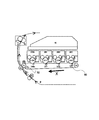
ここで、一次転写部の構成について説明する。図2は図1の一次転写部周辺を拡大した要部断面図である。各一次転写部は、同様の構成である。図2に示すように、転写部材54は非回転状態に支持されており、バネ等の押圧部材62により感光体ドラムに向けて押圧され、図中矢印方向に移動可能な構成となっている。非回転状態に支持された転写部材54は、転写ベルト50の裏面に接する略直方体である。転写部材54は、材質は半導電処理を施された低弾性部材であることが望ましく、例えば発泡ウレタンなどでおおよそ0.8Mpa以下程度が望ましい。転写部材54は主に樹脂製の支持部材58に保持され、押圧部材62により感光体ドラム側へと加圧される。転写部材54は支持部材58に対し接着等により固定されている。また転写部材54は押圧部材62と1ヶ所で接しており、押圧部材62を介して一次転写バイアスを供給されている。押圧部材62は、感光体ドラム21に対して転写部材54を押圧するものである。
Here, the configuration of the primary transfer unit will be described. FIG. 2 is an enlarged cross-sectional view of the main part around the primary transfer part of FIG. Each primary transfer portion has the same configuration. As shown in FIG. 2, the
図3は図2の一次転写部の長手方向(ベルトの回転移動方向と直交する方向)の構成を示す図である。押圧部材62は、感光体ドラム21の画像形成領域L(トナー像を担持する像担持領域)内で、転写部材54を押圧している。ここでは、押圧部材62は、感光体ドラム21の画像形成領域L内であって、転写部材54の前記ベルト50の移動方向と直交する方向の中央1ヶ所を押圧している。また転写部材54は、支持部材58によって形状を保持するように支持されている。ここでは、支持部材58の形状は、図4に示すように転写部材54が挿入される一辺を開放した箱型形状であり、転写部材54の形状を保持するように支持している。また、支持部材58は一般的な樹脂成型部材であり、ヤング率は22〜25Mpa程度である。
FIG. 3 is a diagram showing the configuration of the primary transfer portion in FIG. 2 in the longitudinal direction (direction perpendicular to the rotational movement direction of the belt). The pressing
以上説明したように、上記の構成によれば、一次転写部材54に非回転体を用いることにより、押圧部材62を画像形成領域L内に配置することで長手方向に対する省スペース化が図られることになる。これにより中間転写ベルト50を内包する構造体の長手寸法を小さくすることができる。また非回転体である一次転写部材54の押圧部材62を画像形成領域L内に配置することにより、転写部材54の長手方向の弓なり状の撓み変形を効果的に防止することができる。もしくは撓み変形の程度を極めて小さいものにすることができる。そのため一次転写部材54を支持する支持部材58が極めて強固な剛性を確保していなくとも、転写ニップ部を転写性能を確保するのに必要十分な所定のニップ幅、ニップ圧のものとすることができる。且つそのニップ幅、ニップ圧を転写ニップ部の長手方向に沿って略均一分布にすることができ、押圧力の不均一に起因する転写不良を防止することができる。
As described above, according to the above configuration, by using a non-rotating body for the
また一次転写部材54を略直方体とし、中間転写ベルト50の裏面にその一辺が面接触する構成とすることにより、ニップ幅を任意に設定することができ、性能のよい転写部を構成することができる。
Further, by adopting a configuration in which the
また一次転写部材54を弾性部材で形成し、その形状を保持できる支持部材によって支持することにより、押圧部材62による押圧力を低く設定しても転写ニップ部の長手方向に沿って略均一なニップ幅を形成することができる。このため、転写性能と低負荷を両立させた転写部を構成することができる。
Further, by forming the
〔第2実施形態〕
第2実施形態に係る画像形成装置について説明する。なお、画像形成装置全体の概略構成は前述した実施形態と同様であるため、その説明は援用するものとする。ここでは、構成の異なる一次転写部の構成のみ説明する。図5は図1及び図2の一次転写部の長手方向(ベルトの回転移動方向と直交する方向)の構成を示す図である。前述した実施形態では、押圧部材が、像担持体の像担持領域内で、転写部材を押圧している構成として、長手方向中央1ヶ所を押圧する構成を例示したが、本発明はこれに限定されるものではない。
[Second Embodiment]
An image forming apparatus according to the second embodiment will be described. The overall configuration of the image forming apparatus is the same as that of the above-described embodiment, and the description thereof is incorporated herein. Here, only the configuration of the primary transfer unit having a different configuration will be described. FIG. 5 is a diagram showing the configuration of the primary transfer portion in FIGS. 1 and 2 in the longitudinal direction (direction perpendicular to the rotational movement direction of the belt). In the above-described embodiment, the configuration in which the pressing member presses the transfer member in the image carrying region of the image carrier is exemplified as the configuration in which one central portion in the longitudinal direction is pressed. However, the present invention is not limited to this. Is not to be done.
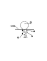
本実施形態では、転写部材54をより均一に感光体ドラム側へと加圧するために、図5に示すように、押圧部材62を転写部材54の端部からEの距離内側に2ヶ所設置させている。
In the present embodiment, in order to press the
本実施形態では、図5に示すように、押圧部材62は、感光体ドラム21の画像形成領域L(トナー像を担持する像担持領域)内であって、転写部材54の前記ベルト50の移動方向と直交する方向端部から等しい距離Eだけ内側の2ヶ所を押圧している。これにより、前述した実施形態に比べて、転写部材54をより均一に感光体ドラム側へ押圧することができる。
In this embodiment, as shown in FIG. 5, the pressing
画像形成領域Lと、押圧部材62を配置する端部からの距離Eと、押圧部材62の押圧力(加重値)による支持部材58の最大変位量(撓み量)は、図6に示す通りである。押圧部材62の配置がE=L/4の位置においての、支持部材58の最大変位量が押圧部材62の配置がE=0の場合に対し、約1/6程度となっている。
The distance E from the image forming region L, the end where the pressing
これに対して、非回転で支持された転写部材54を用いて画像形成領域L外に押圧部材62を設置した場合、支持部材58は転写ニップ内の中央部に弓なり状の撓みを発生させることになり、画像中央部の転写に悪影響を与えることとなる。これを強固な剛性の支持部材(補強部材)を用いることなく回避するために、前述したように、押圧部材62を、画像形成領域L内であって、端部から内側の距離E=L/4近辺の2ヶ所に配置する。これにより、前述した実施形態の効果に加えて更に、強固な補強部材を仕様することなく、より均一なニップ圧を確保することができ、良好な転写を得ることができる。
On the other hand, when the pressing
〔他の実施形態〕
前述した実施形態では、トナー像を担持する中間転写ベルトを用いた画像形成装置を例示し、この画像形成装置における一次転写部に本発明を適用した形態を例示して説明したが、本発明はこれに限定されるものではない。例えば、図7に示すように、記録材を担持する搬送転写ベルトを用いた画像形成装置であっても良い。図7は搬送転写ベルトを用いた画像形成装置の主断面図である。
[Other Embodiments]
In the above-described embodiment, the image forming apparatus using the intermediate transfer belt carrying the toner image is illustrated, and the embodiment in which the present invention is applied to the primary transfer portion in the image forming apparatus has been described as an example. It is not limited to this. For example, as shown in FIG. 7, an image forming apparatus using a transfer transfer belt carrying a recording material may be used. FIG. 7 is a main cross-sectional view of an image forming apparatus using a conveyance transfer belt.
図7に示す画像形成装置内には、矢印X方向に回転移動する無端状の搬送転写ベルト59が配されている。この搬送転写ベルト59は、記録材を担持するベルトであり、半導電処理を施された樹脂などで構成されている。搬送転写ベルト59は、表面をゴム等の摩擦係数の高い材質で覆われた駆動ローラ51によって駆動される。駆動ローラ51は装置本体に配されたモータにより駆動力を供給される。搬送転写ベルト59は駆動ローラ51の他、バネ等の張力印加手段により張架されたテンションローラ53で張架されている。
In the image forming apparatus shown in FIG. 7, an endless
搬送転写ベルト59に接した位置には4つの画像形成部20Bk,20Y,20M,20Cがベルトの回転移動方向に並べて配置されている。これら画像形成部は、それぞれ色の異なるブラック(以下Bk)、イエロー(以下Y)、マゼンタ(以下M)、シアン(以下C)の4つの画像形成部である。各画像形成部には、像担持体としての感光体ドラム21と、この感光体ドラム21に作用するプロセス手段である帯電装置、現像装置、クリーニング装置を有するプロセスカートリッジが着脱可能に配置されている。またプロセスカートリッジにはクリーニング装置により回収された転写残トナーを貯めておく廃トナーボックスが内包され、現像装置内にはBk、Y,M,Cの各色トナーが内包されている。
Four image forming units 20Bk, 20Y, 20M, and 20C are arranged side by side in the rotational movement direction of the belt at a position in contact with the
回転可能な感光体ドラム21には光学ユニット10から画像信号によるレーザー光がポリゴンミラー(不図示)等を介して照射され、感光体ドラム21上に静電画像を形成する。この静電画像に現像装置からトナーを供給することにより現像しトナー像として可視化される。このトナー像が感光体ドラム21の回転に伴って、感光体ドラム21と搬送転写ベルト59が当接する転写部に到達すると、転写部材54に印加した転写バイアスによって、感光体ドラム21上のトナー画像が搬送転写ベルト59に担持された記録材P上に転写される。
The rotatable
同様に搬送転写ベルト59が移動するにつれて第2、第3、第4の画像形成部の各転写部において各トナー像が搬送転写ベルト59に担持された記録材P上に順次重ね合わされて転写される。全てのトナー像が転写された記録材Pは搬送転写ベルト59から剥離され、定着器70へと送られる。定着器70では一対のローラ対により記録材Pに熱と圧力が加えられて、トナー像が記録材Pに定着される。
Similarly, as the
このような搬送転写ベルト59を用いた画像形成装置における各転写部に、前述した実施形態の転写部(図2、図3、図5参照)と同様の構成を適用しても、同様の効果を得ることができる。
Even if the same configuration as that of the transfer unit (see FIGS. 2, 3, and 5) of the above-described embodiment is applied to each transfer unit in the image forming apparatus using such a
また前述した実施形態では、押圧部材が、像担持体の像担持領域内で、転写部材を押圧する構成として、転写部材の長手方向の中央1ヶ所を押圧する構成、転写部材の長手方向端部から等しい距離だけ内側の2ヶ所を押圧する構成を例示した。しかしながら、像担持体に対して転写部材を長手方向にわたって均一に押圧するのであれば、像担持体の像担持領域内における押圧部材の配置、数はこれらに限定されるものではない。 In the above-described embodiment, the pressing member is configured to press the transfer member in the image holding area of the image carrier, and is configured to press one central portion in the longitudinal direction of the transfer member. The structure which presses two places on the inner side by equal distance from the is illustrated. However, the arrangement and the number of pressing members in the image bearing area of the image bearing member are not limited to these as long as the transfer member is uniformly pressed against the image bearing member in the longitudinal direction.
また前述した実施形態では、画像形成部を4つ使用しているが、この使用個数は限定されるものではなく、必要に応じて適宜設定すれば良い。 In the above-described embodiment, four image forming units are used. However, the number of used image forming units is not limited, and may be set as necessary.
また前述した実施形態では、画像形成装置本体に対して着脱自在なプロセスカートリッジとして、感光体ドラムと、該感光体ドラムに作用するプロセス手段としての帯電手段,現像手段,クリーニング手段を一体に有するプロセスカートリッジを例示した。しかしながら、プロセスカートリッジはこれに限定されるものではない。例えば、感光体ドラムの他に、帯電手段、現像手段、クリーニング手段のうち、いずれか1つを一体に有するプロセスカートリッジであっても良い。 In the above-described embodiment, as a process cartridge that is detachable from the main body of the image forming apparatus, a process that integrally includes a photosensitive drum and a charging unit, a developing unit, and a cleaning unit as a process unit that acts on the photosensitive drum. A cartridge was illustrated. However, the process cartridge is not limited to this. For example, in addition to the photosensitive drum, a process cartridge that integrally includes any one of a charging unit, a developing unit, and a cleaning unit may be used.
更に前述した実施形態では、感光体ドラムを含むプロセスカートリッジが画像形成装置本体に対して着脱自在な構成を例示したが、これに限定されるものではない。例えば、各構成部材がそれぞれ組み込まれた画像形成装置、或いは各構成部材がそれぞれ着脱可能な画像形成装置であってもよく、これら画像形成装置における転写部に本発明を適用することにより同様の効果を得ることができる。 Further, in the above-described embodiment, the configuration in which the process cartridge including the photosensitive drum is detachable from the main body of the image forming apparatus is exemplified, but the present invention is not limited to this. For example, it may be an image forming apparatus in which each constituent member is incorporated, or an image forming apparatus in which each constituent member is removable. Similar effects can be obtained by applying the present invention to a transfer portion in these image forming apparatuses. Can be obtained.
また前述した実施形態では、画像形成装置としてプリンタを例示したが、本発明はこれに限定されるものではなく、例えば複写機、ファクシミリ装置等の他の画像形成装置や、或いはこれらの機能を組み合わせた複合機等の他の画像形成装置であっても良い。これら画像形成装置の転写部に本発明を適用することにより同様の効果を得ることができる。 In the above-described embodiments, the printer is exemplified as the image forming apparatus. However, the present invention is not limited to this, and other image forming apparatuses such as a copying machine and a facsimile machine, or a combination of these functions. Other image forming apparatuses such as multifunction peripherals may also be used. The same effect can be obtained by applying the present invention to the transfer portion of these image forming apparatuses.
P …記録材
10 …光学ユニット
20Bk,20Y,20M,20C …画像形成部
21Bk,21Y,21M,21C …感光体ドラム
50 …中間転写ベルト
51 …駆動ローラ
52 …従動ローラ
53 …テンションローラ
54 …転写部材
58 …支持部材
59 …搬送転写ベルト
61 …レジストローラ
62 …押圧部材
70 …定着器
P ... Recording
Claims (7)
前記押圧部材は、前記像担持体の像担持領域内で、前記転写部材を押圧していることを特徴とする画像形成装置。 An image carrier that carries a toner image, a belt that rotates in contact with the image carrier, a non-rotating transfer member that faces the image carrier via the belt, and the image carrier An image forming apparatus having a pressing member that presses the transfer member,
The image forming apparatus according to claim 1, wherein the pressing member presses the transfer member within an image carrying area of the image carrying body.
Priority Applications (1)
| Application Number | Priority Date | Filing Date | Title |
|---|---|---|---|
| JP2012240871A JP2013020278A (en) | 2012-10-31 | 2012-10-31 | Image forming apparatus |
Applications Claiming Priority (1)
| Application Number | Priority Date | Filing Date | Title |
|---|---|---|---|
| JP2012240871A JP2013020278A (en) | 2012-10-31 | 2012-10-31 | Image forming apparatus |
Related Parent Applications (1)
| Application Number | Title | Priority Date | Filing Date |
|---|---|---|---|
| JP2007102519A Division JP5127282B2 (en) | 2007-04-10 | 2007-04-10 | Image forming apparatus |
Publications (2)
| Publication Number | Publication Date |
|---|---|
| JP2013020278A true JP2013020278A (en) | 2013-01-31 |
| JP2013020278A5 JP2013020278A5 (en) | 2013-03-14 |
Family
ID=47691693
Family Applications (1)
| Application Number | Title | Priority Date | Filing Date |
|---|---|---|---|
| JP2012240871A Pending JP2013020278A (en) | 2012-10-31 | 2012-10-31 | Image forming apparatus |
Country Status (1)
| Country | Link |
|---|---|
| JP (1) | JP2013020278A (en) |
Citations (6)
| Publication number | Priority date | Publication date | Assignee | Title |
|---|---|---|---|---|
| JPH08292660A (en) * | 1995-04-20 | 1996-11-05 | Canon Inc | Transfer device |
| JPH09197742A (en) * | 1996-01-19 | 1997-07-31 | Tec Corp | Image forming device |
| JPH10232574A (en) * | 1997-02-20 | 1998-09-02 | Toshiba Corp | Image forming device |
| JP2000214698A (en) * | 1999-01-25 | 2000-08-04 | Canon Inc | Image forming device |
| JP2001083817A (en) * | 1999-09-08 | 2001-03-30 | Canon Inc | Transfer member and image forming device |
| JP5127282B2 (en) * | 2007-04-10 | 2013-01-23 | キヤノン株式会社 | Image forming apparatus |
-
2012
- 2012-10-31 JP JP2012240871A patent/JP2013020278A/en active Pending
Patent Citations (6)
| Publication number | Priority date | Publication date | Assignee | Title |
|---|---|---|---|---|
| JPH08292660A (en) * | 1995-04-20 | 1996-11-05 | Canon Inc | Transfer device |
| JPH09197742A (en) * | 1996-01-19 | 1997-07-31 | Tec Corp | Image forming device |
| JPH10232574A (en) * | 1997-02-20 | 1998-09-02 | Toshiba Corp | Image forming device |
| JP2000214698A (en) * | 1999-01-25 | 2000-08-04 | Canon Inc | Image forming device |
| JP2001083817A (en) * | 1999-09-08 | 2001-03-30 | Canon Inc | Transfer member and image forming device |
| JP5127282B2 (en) * | 2007-04-10 | 2013-01-23 | キヤノン株式会社 | Image forming apparatus |
Similar Documents
| Publication | Publication Date | Title |
|---|---|---|
| JP5127282B2 (en) | Image forming apparatus | |
| JP5835646B2 (en) | Guide device, fixing device, and image forming apparatus | |
| JP4586595B2 (en) | Image forming apparatus and transfer device used therefor | |
| US8204400B2 (en) | Charging device capable of efficiently charging image carrier | |
| JP2013019950A (en) | Belt device, and image forming apparatus | |
| JP5948506B2 (en) | Fixing apparatus and image forming apparatus | |
| JP5613612B2 (en) | Image forming apparatus | |
| US9008564B2 (en) | Image forming apparatus and sheet feeding device | |
| JP2011158495A (en) | Image forming apparatus | |
| JP2013020278A (en) | Image forming apparatus | |
| JP6631143B2 (en) | Image forming device | |
| JP2014191039A (en) | Fixing device and image forming apparatus | |
| JP6182115B2 (en) | Fixing apparatus and image forming apparatus | |
| US9483013B2 (en) | Image forming apparatus having image bearing members | |
| US10429772B2 (en) | Image forming apparatus | |
| JP5274279B2 (en) | Endless belt device and image forming apparatus having the same | |
| JP5990794B2 (en) | Fixing apparatus and image forming apparatus | |
| JP6122797B2 (en) | Fixing apparatus and image forming apparatus | |
| JP4525588B2 (en) | Roller structure, paper conveyance roller structure, belt conveyance roller structure, and image forming apparatus | |
| JP5418841B2 (en) | Fixing apparatus and image forming apparatus | |
| JP6590594B2 (en) | Image forming apparatus | |
| JP6108623B2 (en) | Image forming apparatus | |
| JP6134275B2 (en) | Fixing apparatus and image forming apparatus | |
| JP5492816B2 (en) | Image forming apparatus | |
| JP5364633B2 (en) | Image forming apparatus |
Legal Events
| Date | Code | Title | Description |
|---|---|---|---|
| A621 | Written request for application examination |
Free format text: JAPANESE INTERMEDIATE CODE: A621 Effective date: 20121129 |
|
| A521 | Written amendment |
Free format text: JAPANESE INTERMEDIATE CODE: A523 Effective date: 20121226 |
|
| A131 | Notification of reasons for refusal |
Free format text: JAPANESE INTERMEDIATE CODE: A131 Effective date: 20130402 |
|
| A521 | Written amendment |
Free format text: JAPANESE INTERMEDIATE CODE: A523 Effective date: 20130603 |
|
| A131 | Notification of reasons for refusal |
Free format text: JAPANESE INTERMEDIATE CODE: A131 Effective date: 20130625 |
|
| A521 | Written amendment |
Free format text: JAPANESE INTERMEDIATE CODE: A523 Effective date: 20130826 |
|
| A131 | Notification of reasons for refusal |
Free format text: JAPANESE INTERMEDIATE CODE: A131 Effective date: 20131126 |
|
| A521 | Written amendment |
Free format text: JAPANESE INTERMEDIATE CODE: A523 Effective date: 20140127 |
|
| A02 | Decision of refusal |
Free format text: JAPANESE INTERMEDIATE CODE: A02 Effective date: 20140213 |