JP2013019092A - Method and apparatus for treating textile material - Google Patents
Method and apparatus for treating textile material Download PDFInfo
- Publication number
- JP2013019092A JP2013019092A JP2012152606A JP2012152606A JP2013019092A JP 2013019092 A JP2013019092 A JP 2013019092A JP 2012152606 A JP2012152606 A JP 2012152606A JP 2012152606 A JP2012152606 A JP 2012152606A JP 2013019092 A JP2013019092 A JP 2013019092A
- Authority
- JP
- Japan
- Prior art keywords
- heating cylinder
- fiber material
- air
- air flow
- turning mechanism
- Prior art date
- Legal status (The legal status is an assumption and is not a legal conclusion. Google has not performed a legal analysis and makes no representation as to the accuracy of the status listed.)
- Pending
Links
Images

Classifications
-
- F—MECHANICAL ENGINEERING; LIGHTING; HEATING; WEAPONS; BLASTING
- F26—DRYING
- F26B—DRYING SOLID MATERIALS OR OBJECTS BY REMOVING LIQUID THEREFROM
- F26B13/00—Machines and apparatus for drying fabrics, fibres, yarns, or other materials in long lengths, with progressive movement
- F26B13/06—Machines and apparatus for drying fabrics, fibres, yarns, or other materials in long lengths, with progressive movement with movement in a sinuous or zig-zag path
- F26B13/08—Machines and apparatus for drying fabrics, fibres, yarns, or other materials in long lengths, with progressive movement with movement in a sinuous or zig-zag path using rollers
-
- D—TEXTILES; PAPER
- D06—TREATMENT OF TEXTILES OR THE LIKE; LAUNDERING; FLEXIBLE MATERIALS NOT OTHERWISE PROVIDED FOR
- D06C—FINISHING, DRESSING, TENTERING OR STRETCHING TEXTILE FABRICS
- D06C7/00—Heating or cooling textile fabrics
-
- F—MECHANICAL ENGINEERING; LIGHTING; HEATING; WEAPONS; BLASTING
- F26—DRYING
- F26B—DRYING SOLID MATERIALS OR OBJECTS BY REMOVING LIQUID THEREFROM
- F26B13/00—Machines and apparatus for drying fabrics, fibres, yarns, or other materials in long lengths, with progressive movement
- F26B13/10—Arrangements for feeding, heating or supporting materials; Controlling movement, tension or position of materials
- F26B13/14—Rollers, drums, cylinders; Arrangement of drives, supports, bearings, cleaning
- F26B13/18—Rollers, drums, cylinders; Arrangement of drives, supports, bearings, cleaning heated or cooled, e.g. from inside, the material being dried on the outside surface by conduction
-
- D—TEXTILES; PAPER
- D06—TREATMENT OF TEXTILES OR THE LIKE; LAUNDERING; FLEXIBLE MATERIALS NOT OTHERWISE PROVIDED FOR
- D06F—LAUNDERING, DRYING, IRONING, PRESSING OR FOLDING TEXTILE ARTICLES
- D06F65/00—Ironing machines with rollers rotating against curved surfaces
- D06F65/02—Ironing machines with rollers rotating against curved surfaces with one roller only
-
- D—TEXTILES; PAPER
- D06—TREATMENT OF TEXTILES OR THE LIKE; LAUNDERING; FLEXIBLE MATERIALS NOT OTHERWISE PROVIDED FOR
- D06F—LAUNDERING, DRYING, IRONING, PRESSING OR FOLDING TEXTILE ARTICLES
- D06F67/00—Details of ironing machines provided for in groups D06F61/00, D06F63/00, or D06F65/00
Abstract
Description
本発明は、繊維材料を処理するための方法であって、処理剤が繊維材料に塗布され、繊維材料が少なくとも1つの加熱シリンダ上で乾燥させられるものに関する。
本発明はさらに、繊維材料を処理するための装置であって、処理剤塗布部と乾燥部とを有し、乾燥部が少なくとも1つの加熱シリンダを有し、乾燥時に加熱シリンダの周面に繊維材料が当接するものに関する。
The present invention relates to a method for treating a fiber material, wherein a treating agent is applied to the fiber material and the fiber material is dried on at least one heating cylinder.
The present invention is further an apparatus for treating a fiber material, which has a treatment agent application part and a drying part, the drying part has at least one heating cylinder, and the fiber is provided on the peripheral surface of the heating cylinder during drying It relates to the material that abuts.
本発明は以下で繊維材料を例に述べるが、この繊維材料は経糸の態様、つまり給糸器の態様で存在し、サイジング剤を備えられる。このサイジング剤は乾燥させられねばならない。しかし本発明は別の状況においても、例えば繊維材料に染料を塗布後にまたは繊維材料の洗浄後にも、利用することができる。
繊維糸はしばしば比較的粗い表面を有する。この粗さが他の処理、例えば製織を困難にする。それゆえに繊維材料は、継続処理前に、主成分として例えばデンプンを含むことのあるサイジング剤が備えられる。サイジング剤は表面に一定の平滑さをもたらし、こうして処理時に擦れ合う糸表面間の摩擦を減らす。
The present invention will be described below by taking a fiber material as an example, and this fiber material exists in the form of warp, that is, in the form of a yarn feeder and is provided with a sizing agent. This sizing agent must be dried. However, the invention can also be used in other situations, for example after applying the dye to the fiber material or after washing the fiber material.
Fiber yarns often have a relatively rough surface. This roughness makes other processes such as weaving difficult. Therefore, the fiber material is provided with a sizing agent which may contain, for example, starch as a main component prior to continued processing. Sizing agents provide a level of smoothness to the surface, thus reducing friction between yarn surfaces that rub during processing.
サイジング剤を塗布するために、繊維材料はふつう液体を付加され、この液体にサイジング剤が溶かしてある。例えば繊維材料はサイジング剤液を充填した槽に通されることができる。サイジング剤液の塗布方式にかかわりなく繊維材料はサイジング剤液の塗布後、サイジング剤が糸の表面に留まるだけとなるように乾燥されねばならない
乾燥する1つの可能性は、例えば繊維材料の速度に一致した周速度で動く加熱シリンダの周面の一部にわたって繊維材料を案内することにある。加熱シリンダは高い表面温度を有し、加熱シリンダは繊維材料に熱を供給することができる。この熱はサイジング剤液の揮発成分を蒸発させ、一定の乾燥時間後に繊維材料は乾燥しており、サイジング剤が糸の表面に留まるだけである。
この処理手順は確かにその価値を実証されたが、しかし比較的エネルギー支出を要し、そのことで費用が高くなる。
In order to apply the sizing agent, the fiber material is usually added with a liquid in which the sizing agent is dissolved. For example, the fiber material can be passed through a tank filled with a sizing agent solution. Regardless of the application method of the sizing agent solution, the fiber material must be dried after the sizing agent solution is applied so that the sizing agent only remains on the surface of the yarn.One possibility of drying is, for example, the speed of the fiber material. It is to guide the fiber material over a portion of the peripheral surface of the heating cylinder that moves at a consistent peripheral speed. The heating cylinder has a high surface temperature and the heating cylinder can supply heat to the fiber material. This heat evaporates the volatile components of the sizing agent liquid, and after a certain drying time, the fiber material is dry and the sizing agent only remains on the surface of the yarn.
This processing procedure has indeed proven its value, but it is relatively energy intensive, which makes it expensive.
本発明の課題は、安価な処理を可能とすることである。 An object of the present invention is to enable inexpensive processing.
この課題は、冒頭に指摘した種類の方法において、加熱シリンダに接した繊維材料が空気流を付加され、加熱シリンダの上流側で繊維材料が転向機構を介して案内され、この転向機構が、非接触式に作動し付着防止表面を有し温度調節されているとの条件のうち少なくとも1つを満たすことによって解決される。 The problem is that, in the method of the type pointed out at the beginning, the fiber material in contact with the heating cylinder is added with an air flow, and the fiber material is guided through the turning mechanism upstream of the heating cylinder. The problem is solved by satisfying at least one of the conditions of contact-type operation, anti-adhesion surface and temperature control.
空気流は加熱シリンダ周面の少なくとも一部で繊維材料に対して一定の押付圧力を加え、繊維材料と加熱シリンダ周面との間の接触が改善される。
それとともに加熱シリンダから繊維材料への熱伝達も改善され、それとともにエネルギー収率が改善される。空気流は同時に処理剤、例えばサイジング剤液の揮発成分を搬出することができ、繊維材料の周囲でこれら諸成分の蒸気圧力が低下する。そのことからやはり揮発成分のさらなる蒸発が容易となる。
繊維材料は加熱シリンダの上流側で転向機構を介して案内される。こうして、加熱シリンダ上の繊維材料の載置ゾーンの始端を決定することが可能となる。転向機構の性質によって、処理剤が既に転向機構上に沈降することは防止される。処理剤はむしろ繊維材料上に留まり、次に加熱シリンダで乾燥させることができる。
The air flow applies a constant pressing pressure on the fiber material at least at a portion of the heating cylinder circumferential surface, improving the contact between the fiber material and the heating cylinder circumferential surface.
At the same time, the heat transfer from the heating cylinder to the fiber material is improved, and the energy yield is improved. The air stream can simultaneously carry away the volatile components of the treatment agent, such as the sizing agent liquid, and the vapor pressure of these components decreases around the fiber material. Therefore, further evaporation of volatile components is facilitated.
The fiber material is guided via a turning mechanism upstream of the heating cylinder. In this way, it is possible to determine the starting end of the placement zone of the fiber material on the heating cylinder. The nature of the turning mechanism prevents the treatment agent from already settling on the turning mechanism. Rather, the treatment agent remains on the fiber material and can then be dried in a heated cylinder.
空気流が加熱されているのが好ましい。従って、繊維材料の加熱シリンダに当接しない側にも熱が供給される。そのことの他の利点として加熱シリンダから周囲への熱放射が減らされ、そのことからやはり、加熱シリンダから放出される熱の繊維材料による利用が改善される。そのことからもエネルギー消費量が低下し、従って費用が低下する。
好ましくは、空気流が入口領域において加熱シリンダに対して接線方向に向けられる。このような流れが生じるのは、例えば、空気流が周方向の1つの位置または若干数の位置でのみ加熱シリンダの周面に向けられる場合である。そこでは繊維材料が空気流によって比較的強く加熱ドラムに押し付けられる。しかし、空気流はそこから加熱シリンダ周面の別の諸領域に達することもでき、そこで空気流は次に実質的に接線方向に流れる。そのことは特に入口領域において有利である。なぜならば、空気流は次に、達する繊維材料に付着した空気層をいわば剥離できるからである。こうして、実質的に空気流によって搬送されて繊維材料の乾燥に利用される空気を、所望の如く、状態調節することができる。
It is preferred that the air stream is heated. Accordingly, heat is also supplied to the side of the fiber material that does not contact the heating cylinder. Another advantage of this is that heat radiation from the heating cylinder to the environment is reduced, which again improves the utilization of the heat released from the heating cylinder by the fiber material. This also reduces energy consumption and thus costs.
Preferably, the air flow is directed tangential to the heating cylinder in the inlet region. Such a flow occurs, for example, when the air flow is directed to the circumferential surface of the heating cylinder only at one or a few positions in the circumferential direction. There, the fiber material is pressed relatively strongly against the heating drum by the air flow. However, the air flow can also reach other regions of the heated cylinder surface from which the air flow then flows substantially tangentially. This is particularly advantageous in the inlet region. This is because the air flow can then peel off the air layer attached to the fiber material that reaches it. In this way, the air carried by the air stream and utilized for drying the fiber material can be conditioned as desired.
好ましくは、空気流の空気は、少なくとも一部が循環される。このことは、特に加熱された空気流の場合、エネルギー上の観点の下で有利である。確かにすべての空気が繊維材料の再付加用に回収できるのではない。既に一度繊維材料に付加された空気はしばしば一定の冷却を受けることにもなる。それでもなお循環路内で案内される空気はなお一定の熱含量を有し、熱は新たに供給する必要がなく、この熱含量を再利用することができる。
好ましくは、空気流が加熱シリンダの周面領域で供給され、かつ加熱シリンダの軸線と平行に排出される。それとともに空気流は繊維材料を加熱シリンダの周面に押し付けることができ、この作用が排出される空気によって相殺されることはない。
Preferably, the air stream air is at least partially circulated. This is advantageous from an energy point of view, especially in the case of a heated air stream. Certainly not all air can be recovered for re-addition of fiber material. Air once added to the fiber material often also undergoes constant cooling. Nevertheless, the air guided in the circulation path still has a certain heat content, and no heat needs to be supplied, and this heat content can be reused.
Preferably, an air flow is supplied in the peripheral area of the heating cylinder and discharged parallel to the axis of the heating cylinder. Along with that, the air flow can press the fiber material against the peripheral surface of the heating cylinder, and this action is not offset by the exhausted air.
好ましくは、加熱シリンダをその周面の少なくとも一部にわたって取り囲むハウジング内で空気流は案内される。このハウジングが有する他の利点として、ここで一定の熱遮蔽を達成することができ、周囲に放出される熱エネルギーが少なくなる。そのことから一方でエネルギーがかなり節約される。他方で、周囲もそんなに強く昇温されず、そのことが装置周辺での作業条件に肯定的に作用する。
好ましくは、繊維材料が加熱シリンダの上流側で照射される。使用される処理剤に依存して、照射によって特定の作用を生成することができる。処理剤の揮発成分または水性成分のみを取り除きたい場合、照射でもって例えば既に熱を供給することができる。別の処理剤を使用する場合、例えば‐好適な照射を前提に‐化学変換プロセスを付け加えることができ、その場合この変換プロセスは加熱シリンダ上での乾燥時に進展する。
Preferably, the air flow is guided in a housing surrounding the heating cylinder over at least a part of its peripheral surface. Another advantage of this housing is that a certain thermal shielding can be achieved here and less heat energy is released to the surroundings. On the other hand, it saves a lot of energy. On the other hand, the surroundings are not heated so strongly, which positively affects the working conditions around the apparatus.
Preferably, the fiber material is irradiated upstream of the heating cylinder. Depending on the treatment agent used, specific effects can be produced by irradiation. If it is desired to remove only the volatile or aqueous components of the treatment agent, for example, heat can already be supplied with irradiation. If another treatment agent is used, for example-on the premise of suitable irradiation-a chemical conversion process can be added, in which case the conversion process proceeds upon drying on a heated cylinder.
その際好ましくは、照射のために熱放射が利用される。熱放射、つまり赤外線放射は、比較的簡単に発生することができ、ハンドリングの点で殆ど危険がなく、繊維材料の温度を高めることになる。こうして、付加的に加熱シリンダによって供給される熱でもって比較的迅速な乾燥を達成することができる。
好ましくは、転向のために空気流が利用される。空気流でもって転向は非接触式に行うことができる。すなわち、転向時に処理剤が転向機構で剥ぎ取られまたは処理剤が転向機構に堆積する虞はない。転向のために例えば、空気クッション上で繊維材料を案内するいわゆる「エアターン」を利用することができる。
In this case, preferably, thermal radiation is used for irradiation. Thermal radiation, i.e. infrared radiation, can be generated relatively easily, with little danger in handling and will increase the temperature of the fiber material. Thus, relatively quick drying can be achieved with the heat additionally supplied by the heating cylinder.
Preferably, an air flow is utilized for turning. The turning can be done in a non-contact manner with an air flow. That is, there is no possibility that the processing agent is peeled off by the turning mechanism or deposited on the turning mechanism during turning. For turning, for example, so-called “air turns” can be used which guide the fiber material on an air cushion.
好ましくは、空気流が温度調節されている。温度調節によって同様に処理剤に影響を及ぼすことができる。この温度調節は、例えば処理剤の諸成分を固定化するための冷却とすることができ、またいわば一種の予備乾燥を行うための加熱とすることもできる。
課題は、冒頭に記載した種類の装置において、加熱シリンダに当接した繊維材料に向けた空気流を発生する空気流発生機構が設けられており、加熱シリンダの上流側に転向機構が配置されており、この転向機構が、非接触式に作動し付着防止表面を有し温度調節されているとの条件のうち少なくとも1つを満たすことによって解決される。
Preferably, the air flow is temperature controlled. The treatment agent can be similarly affected by adjusting the temperature. This temperature control can be, for example, cooling for immobilizing various components of the treatment agent, or, in other words, heating for performing a kind of preliminary drying.
The problem is that in the apparatus of the type described at the beginning, an air flow generating mechanism for generating an air flow toward the fiber material in contact with the heating cylinder is provided, and a turning mechanism is disposed upstream of the heating cylinder. This turning mechanism is solved by satisfying at least one of the conditions that the non-contact operation, the anti-adhesion surface, and the temperature are controlled.
方法に関連して上で既に述べたように、空気流は繊維材料を一定の圧力で加熱シリンダの周面に押し付けることができ、こうして加熱シリンダと繊維材料との間の熱伝達が改善される。この熱伝達が良ければ良いほど、エネルギー収率も一層良好となる。その場合、一層多くの処理剤を同じ時間内に蒸発させることができ、または同量の処理剤を蒸発させたい場合に費やす熱エネルギーを一層少なくすることができる。転向機構によって巻付きの始端は規定することができ、処理剤が転向機構を過度に強く汚すことはない。 As already mentioned above in connection with the method, the air stream can press the fiber material against the peripheral surface of the heating cylinder at a constant pressure, thus improving the heat transfer between the heating cylinder and the fiber material. . The better this heat transfer, the better the energy yield. In that case, more processing agent can be evaporated in the same time, or less heat energy can be spent if the same amount of processing agent is desired to evaporate. The turning mechanism can define the winding start, and the treatment agent does not stain the turning mechanism too strongly.
好ましくは、空気流発生機構が加熱機構を有する。この加熱機構は、空気流を加熱するのに利用することができる。空気流が同様に高い温度を有する場合、加熱シリンダの側から熱が繊維材料に放出されるだけでなく、付加的に他の熱源、つまり空気流の加熱された空気も利用可能である。空気流のこの空気は、処理剤の既に蒸発した諸成分を搬出するのにも利用することができる。これにより繊維材料の周囲でこれら諸成分の蒸気圧力が低下するので、繊維材料に付着した処理剤からこれらの諸成分をさらに蒸発させるのに必要な熱エネルギーは少なくなる。
好ましくは、空気流発生機構が空気流を少なくとも入口領域において加熱シリンダに対して接線方向に向ける。次に空気流はこの入口領域において、なお周囲に由来する空気を繊維材料から剥離することができる。この措置でもって、空気流のうち乾燥のために付加的に利用される空気は最適乾燥結果を達成できるように調節することができる。
Preferably, the air flow generation mechanism has a heating mechanism. This heating mechanism can be used to heat the air stream. If the air stream has a similarly high temperature, not only heat is released to the fiber material from the side of the heating cylinder, but also other heat sources, ie heated air of the air stream, are available. This air in the air stream can also be used to carry out the already evaporated components of the treatment agent. This reduces the vapor pressure of these components around the fiber material, so less thermal energy is required to further evaporate these components from the treating agent adhering to the fiber material.
Preferably, the air flow generating mechanism directs the air flow tangential to the heating cylinder at least in the inlet region. The air stream can then release air from the surroundings from the fiber material in this inlet region. With this measure, the air additionally used for drying in the air stream can be adjusted to achieve an optimum drying result.
好ましくは、空気流発生機構は加熱シリンダを少なくとも部分的に取り囲むハウジングを有する。このハウジングは周囲への熱放射を僅かなものに抑えることができる。ハウジングは同時に、繊維材料の乾燥にとって良好な状況が生じるように所望の如く、空気流を案内することを可能とする。
好ましくは、ハウジングは加熱シリンダの軸線方向伸長領域に配置される少なくとも1つの給気口とハウジングの正面壁に配置される少なくとも1つの排気口とを有する。それとともに吸気口は空気流をハウジングの内部に向ける。この空気流は加熱シリンダの方向で繊維材料に対して圧力を生成する。繊維材料に付加された空気は次に横から排気口を通して逃げることができる。排気口はハウジングの正面壁に配置されており、この正面壁は加熱シリンダの軸線に対して略垂直に向いている。こうして、加熱シリンダの軸線と平行な排気方向を生成することができる。
Preferably, the air flow generating mechanism has a housing that at least partially surrounds the heating cylinder. This housing can suppress heat radiation to the surroundings to a slight extent. The housing at the same time allows the air flow to be guided as desired so that a good situation occurs for the drying of the fiber material.
Preferably, the housing has at least one air supply port arranged in the axially extending region of the heating cylinder and at least one exhaust port arranged in the front wall of the housing. At the same time, the air inlet directs the air flow into the housing. This air flow creates pressure on the fiber material in the direction of the heating cylinder. The air added to the fiber material can then escape from the side through the exhaust. The exhaust port is arranged in the front wall of the housing, and this front wall faces substantially perpendicular to the axis of the heating cylinder. In this way, an exhaust direction parallel to the axis of the heating cylinder can be generated.
好ましくは、吸気口と排気口が循環路を介して互いに接続されている。この循環路中に例えばベンチレータ等の移送手段が配置されている。空気流の全ての空気を循環路内で案内できないとしても、これによりエネルギー回収によってかなりの節約が得られる。排気口を通してハウジングから取り出される空気もなお高い温度を有し、従って繊維材料の他の処理用に利用することのできる高い熱含量を有する。
好ましくは、繊維材料に作用する照射機構が加熱シリンダの上流側に配置されている。方法に関連して上で述べたように、処理剤内で特定の諸作用を達成するためにまたは繊維材料を処理剤で簡単に予熱するために、加熱シリンダ上に接する前に繊維材料は照射することができる。
Preferably, the intake port and the exhaust port are connected to each other via a circulation path. Transfer means such as a ventilator is disposed in the circulation path. Even if not all the air in the air flow can be guided in the circuit, this provides a considerable savings by energy recovery. The air drawn from the housing through the exhaust port still has a high temperature and thus has a high heat content that can be utilized for other processing of the fiber material.
Preferably, an irradiation mechanism acting on the fiber material is arranged upstream of the heating cylinder. As mentioned above in connection with the method, the fiber material is irradiated before it is contacted on the heating cylinder in order to achieve certain functions within the treatment agent or to simply preheat the fiber material with the treatment agent. can do.
その際好ましくは、照射機構が赤外線放射器として形成されている。このような赤外線放射器は繊維材料の両側に配置しておくことも十分に可能であり、繊維材料に熱放射を向けて繊維材料を加熱することができる。
好ましくは、転向機構が空気噴流転向機構として形成されている。このような空気噴流転向機構は「エアターン」の名称でも知られており、空気クッションを生成する。転向時に繊維材料はこの空気クッションに載置されまたは空気クッションによって支えられる。空気クッションは当然に持続的に更新されねばならない。換言するなら、空気は持続的に補給されねばならない。
In this case, the irradiation mechanism is preferably formed as an infrared radiator. Such infrared radiators can be sufficiently arranged on both sides of the fiber material, and the fiber material can be heated by directing heat radiation to the fiber material.
Preferably, the turning mechanism is formed as an air jet turning mechanism. Such an air jet turning mechanism is also known by the name “air turn” and produces an air cushion. When turning, the fiber material is placed on or supported by the air cushion. The air cushion must of course be updated continuously. In other words, the air must be replenished continuously.
その際好ましくは、空気噴流転向機構が温度調節機構を有する。この温度調節機構は空気クッションに供給された空気を加温または冷却することができる。冷却すると処理剤の諸成分の一定の固定化を達成することができ、加熱シリンダ上に堆積する虞は軽減される。そうする代わりに空気は加温することもでき、一種の予備乾燥が得られる。
以下、好ましい実施例に基づいて図面と合わせて本発明を説明する。
In that case, preferably, the air jet turning mechanism has a temperature adjusting mechanism. This temperature adjustment mechanism can heat or cool the air supplied to the air cushion. When cooled, the components of the processing agent can be fixed and the possibility of depositing on the heating cylinder is reduced. Instead, the air can be warmed, resulting in a kind of pre-drying.
The present invention will be described below with reference to the drawings based on preferred embodiments.
本発明は以下でサイジング剤の塗布に基づいて述べる。この場合、サイジング剤が処理剤である。しかし本発明は別の事例において、例えば繊維材料を染色または印刷しまたは繊維材料を単純に洗浄するときに、応用することができる。
本発明は以下、給糸器内にある繊維材料に基づいて述べる。しかし本発明は別の態様の繊維材料、例えば事前に製織、製編、製組または別の方法で製造された平面的に形成された繊維材料においても応用することができる。
The invention is described below on the basis of application of a sizing agent. In this case, the sizing agent is a treatment agent. However, the invention can be applied in other cases, for example when dyeing or printing fiber materials or simply washing fiber materials.
The invention will be described below on the basis of the fiber material in the yarn feeder. However, the present invention can also be applied to other forms of fiber material, for example, planarly formed fiber material that has been pre-woven, knitted, braided or otherwise manufactured.
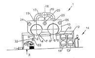
給糸器の形式で繊維材料2をサイジングするための装置1が、サイジング剤塗布部3を有し、この塗布部内で繊維材料2にサイジング剤が付加される。サイジング剤はさまざまな構成とすることができ、例えばサイジング剤を担体液に分散させた分散体とすることができ、直接に液状サイジング剤とすることもできる。サイジング剤は発泡体またはペーストとすることもできる。いずれにしても繊維材料2はサイジング剤の塗布時に湿潤され、または少なくとも加湿される。サイジング剤の態様とサイジング剤を繊維材料2に塗布する方式とにかかわりなく、繊維材料2はサイジング剤の塗布後に乾燥させる必要がある。
乾燥のために繊維材料2は2つの加熱シリンダ4、5を介して誘導される。繊維材料2を極力大きな周面部分にわたって加熱シリンダ4、5で保持するために転向機構6〜9が設けられている。転向機構6〜9が図1ではローラとして示してある。しかし転向機構は、さらに後に詳しく述べるように、別の態様を有することもできる。加熱シリンダは、例えば加熱シリンダ4、5の内部に持ち込まれる蒸気を頼りに加熱されている。加熱シリンダ4、5は高い表面温度を有し、載置された繊維材料2に熱を放出することができる。この熱は繊維材料2に付着したサイジング剤液も加熱して蒸発させ、最終的にサイジング剤が繊維材料2の糸に留まるだけとなる。
The apparatus 1 for sizing the
For drying, the
転向機構6〜9は、繊維材料2が加熱シリンダ4、5にその周面の極力大きな部分にわたって巻き付くように配置されている。転向機構6は加熱シリンダ4の周りでの巻付きの始端を規定し、転向機構7は加熱シリンダ4の周りでの巻付きの終端を規定する。同様に、転向機構8は加熱シリンダ5の周りでの巻付きの始端を規定し、転向機構9は加熱シリンダ5の周りでの巻付きの終端を規定する。加熱シリンダ4、5の周りでの巻付き角度を変更できるように転向機構6〜9は変位可能とすることができる。しかし一般に、繊維材料2が加熱シリンダ4、5にその周面の極力大きな部分にわたって巻き付くと有利となる。
繊維材料の走行方向で加熱シリンダ4、5の下流側に、繊維材料が出口14で装置から進出する前に再乾燥シリンダ10〜13が配置されている。
The turning
加熱シリンダ4、5は少なくとも部分的にハウジング15によって取り囲まれている。ハウジング15は加熱シリンダ4、5をそれぞれその周面の半分以上にわたって包み込む。
ハウジング15は給気通路16と接続されており、この給気通路は2つの分岐17、18を介してハウジング15の給気口19、20と接続されている。装置1の他の構成要素を認めることができるように、給気通路16は図2に中断して図示されている。
両方の給気口19、20は加熱シリンダ4、5の周面を向くように配置されている。その場合、給気通路16内を流れる空気が形成する空気流は給気口19、20を通して加熱シリンダ4、5の周面に向けられている。この空気流によって、繊維材料2は高い圧力で加熱シリンダ4、5の周面に押し付けられることになる。
給気通路16が加熱機構21と接続されており、給気通路16を通してハウジング15に送り込まれる空気は加温することができる。加温された空気は、乾燥が促進されるように繊維材料2に熱を持ち込むのにも寄与する。
The heating cylinders 4, 5 are at least partly surrounded by a
The
Both the
The
同時に、ハウジング15内で空気流は入口領域において、つまり走行方向で第1転向ローラ6の下流側で、加熱シリンダ4に対して接線方向で繊維材料2に衝突するように向けられている。こうして、供給された空気は繊維材料2に付着した空気をいわば剥離することができ、ハウジング15の内部で繊維材料2に付加するために利用される空気が相応に状態調節された空気であることは簡単に確保することができる。同様に、給気口20を通して第2加熱シリンダ5に供給される空気も当然に走行方向で転向ローラ8の下流側の領域を付加し、そこで繊維材料2から空気を剥離することができる。
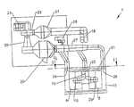
空気流を発生するために給気通路16はモータ23によって駆動される送風機22と接続されている。
At the same time, the air flow in the
The
特に図2から認めることができるように、両方の給気口19、20は加熱シリンダ4、5の軸線方向伸長の中央でハウジング15に注ぐように配置されている。こうして供給される空気の大部分は、排気通路27に接続された排気口24〜26を介してハウジング15から取り出される。このため排気通路27が排気送風機28と接続されており、この排気送風機はハウジング15から排気を吸引して濾過機構29内に移送する。濾過機構29から空気は送風機22に送られる。このため、送風機22を濾過機構29と接続する通路部分30が設けられている。つまり空気はいずれにしても一部が循環路内で案内される。
排気口24、25、26はハウジングの正面壁31に配置されている。この正面壁31は加熱シリンダ4、5の正面と平行に延びている。その際、給気口19、20の軸線と平行に排気口24〜26と加熱シリンダ4、5との間に重なりが生じないかまたはせいぜい僅かな重なりが生じるように排気口24〜26は加熱シリンダ4、5の横に配置されている。
As can be seen in particular from FIG. 2, both
The
塗布部3と第1転向機構6との間に配置されている2つの赤外線放射器32、33がそれぞれに熱放射を発生する。この熱放射は繊維材料2の両側に向けられている。赤外線放射器32、33からの熱放射によって、サイジング剤を被着された繊維材料2はサイジング剤を塗布するのに使用された液体の一部が既に蒸発できるほどに既に高い温度となる。処理剤に依存して、別の放射を使用する別の放射発生器も当然使用することができる。処理剤内で特定の化学過程を引き起こすために例えば紫外線放射を発生することが考えられよう。
Two
図3は、転向機構6の第1構成を示す。残りの転向機構7〜9はまったく同じに形成しておくことができる。しかし転向機構は単純に転向ローラとして形成しておくこともできる。
転向機構6は表面35を備えた転向ローラ34を有する。この表面35に、例えばポリテトラフルオロエチレンから成る付着防止被覆が配置されている。この付着防止被覆によって、サイジング剤または別の処理剤が転向ローラ34に堆積して時間の経過とともに傷害を生じ得ることはない。転向ローラ34の表面35は当然に別の仕方で付着しないように形成することができる。
加熱機構36は表面35に作用し、稼動時に表面35が加温されるようにする。その場合表面35の熱が繊維材料2に伝達され、そのことからやはり、サイジング剤または別の処理剤が転向ローラ34に付着することは防止されることになる。使用される処理剤に依存して、転向ローラ34の冷却がサイジング剤または別の処理剤の付着を防止するとき加熱機構36の代わりに冷却機構を使用することが有意義なこともある。転向ローラ34は別の仕方で、例えば温度調節された液体または温度調節されたガスを内側から送ることによって、温度調節することもできる。
FIG. 3 shows a first configuration of the
The
The
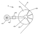
図4は転向機構6の第2構成を示す。転向機構6がここでは、「エアターン」とも称される空気噴流転向機構37を有する。空気噴流転向機構37がハウジング38を有し、このハウジングは繊維材料2に向き合う側がほぼ円筒状に形成されている。この側に注ぐ複数の通路39は供給通路40から供給を受け、この供給通路はハウジング38の長さにわたって(図示平面に垂直に)延びている。通路39は当然に、図示したようにハウジング38の繊維材料2に向き合う側にわたって分布しているだけでなく、ハウジング38の長さにわたっても分布している。
供給通路40は、送風機41によって供給される空気を高圧で供給される。送風機41と供給通路40との間の管路42中に温度調節機構43が配置されており、この温度調節機構は通路39を通して放出される空気流を加熱するかまたは冷却する。温度調節の方式は使用されるサイジング剤または別の処理剤に応じて決まる。
FIG. 4 shows a second configuration of the
The
図示した処理方式によって装置1の能力は著しく高めることができる。時間当り比較的多くの繊維材料2を乾燥させることができるので、繊維材料2は高速でサイジングすることができる。同時に、繊維材料2の面積当り乾燥させるのに必要なエネルギーが少なくなり、エネルギー費用が節約される。装置の長さは比較的短いものに抑えることができる。
The capacity of the device 1 can be significantly increased by the illustrated processing method. Since a relatively large amount of
Claims (20)
前記加熱シリンダ(4、5)に当接した前記繊維材料(2)が空気流を付加される工程と、前記加熱シリンダ(4、5)の上流側で前記繊維材料が転向機構(6)を介して案内される工程とを有し、
前記転向機構は、非接触式に作動すること、付着防止表面を有すること、及び温度調節されているとの条件のうち少なくとも1つを満たすことを特徴とする方法。 A method for treating a fiber material (2), wherein a treating agent is applied to the fiber material (2) and the fiber material (2) is dried on at least one heating cylinder (4, 5) In things,
The fiber material (2) in contact with the heating cylinder (4, 5) is subjected to a process of adding an air flow, and the fiber material has a turning mechanism (6) upstream of the heating cylinder (4, 5). And a process guided through
The method is characterized in that the turning mechanism satisfies at least one of the following conditions: operating in a non-contact manner, having an adhesion preventing surface, and being temperature controlled.
前記加熱シリンダに載った前記繊維材料(2)に向けた空気流を発生する空気流発生機構(15〜22)が設けられており、
前記加熱シリンダ(4、5)の上流側に転向機構(8)が配置されており、
前記転向機構は、非接触式に作動する、付着防止表面を有する、温度調節されているとの条件のうち少なくとも1つを満たすことを特徴とする装置。 An apparatus for treating a fiber material (2), comprising a treatment agent application part (3) and a drying part, wherein the drying part comprises at least one heating cylinder (4, 5) In what the fiber material (2) abuts on the peripheral surface of the heating cylinder,
An air flow generation mechanism (15-22) for generating an air flow toward the fiber material (2) mounted on the heating cylinder is provided;
A turning mechanism (8) is disposed upstream of the heating cylinder (4, 5),
The device is characterized in that the turning mechanism satisfies at least one of the conditions that it operates in a non-contact manner, has an anti-adhesion surface, and is temperature-controlled.
Applications Claiming Priority (2)
| Application Number | Priority Date | Filing Date | Title |
|---|---|---|---|
| DE102011107126.5A DE102011107126B4 (en) | 2011-07-12 | 2011-07-12 | Method and device for treating a textile product |
| DE102011107126.5 | 2011-07-12 |
Publications (1)
| Publication Number | Publication Date |
|---|---|
| JP2013019092A true JP2013019092A (en) | 2013-01-31 |
Family
ID=45999538
Family Applications (1)
| Application Number | Title | Priority Date | Filing Date |
|---|---|---|---|
| JP2012152606A Pending JP2013019092A (en) | 2011-07-12 | 2012-07-06 | Method and apparatus for treating textile material |
Country Status (5)
| Country | Link |
|---|---|
| EP (1) | EP2546406B1 (en) |
| JP (1) | JP2013019092A (en) |
| CN (1) | CN102877245B (en) |
| DE (1) | DE102011107126B4 (en) |
| ES (1) | ES2913333T3 (en) |
Families Citing this family (7)
| Publication number | Priority date | Publication date | Assignee | Title |
|---|---|---|---|---|
| BE1022093B1 (en) * | 2014-04-07 | 2016-02-15 | Werkhuizen Lapauw Nv | MANGEL FAIR FOR A IRONING MACHINE |
| CN106568313B (en) * | 2016-11-08 | 2018-12-14 | 长兴县大伟纺织有限公司 | A kind of textile cloth quick-dehumidifying device |
| CN108534516A (en) * | 2018-04-10 | 2018-09-14 | 湖州练市天龙纺织有限公司 | A kind of weaving loom cloth drying device |
| CN108914460A (en) * | 2018-08-29 | 2018-11-30 | 江苏阳光毛纺服装技术开发有限公司 | A kind of quick blowing-dry apparatus for garment material production |
| CN109539743A (en) * | 2018-12-29 | 2019-03-29 | 无锡启成新能源有限公司 | A kind of novel lithium ion battery diaphragm drying box |
| CN112981821B (en) * | 2021-03-04 | 2022-04-22 | 浙江工业职业技术学院 | Exhaust treatment device for drying fabric |
| CN114432866B (en) * | 2022-02-10 | 2022-12-09 | 绍兴达伽马纺织有限公司 | Knitted fabric shaping waste gas spraying equipment with heat energy recovery function |
Citations (12)
| Publication number | Priority date | Publication date | Assignee | Title |
|---|---|---|---|---|
| JPS61114241A (en) * | 1984-11-08 | 1986-05-31 | Daitoo Kk | Film drying device of automatic developing machine |
| JPH01321994A (en) * | 1988-04-25 | 1989-12-27 | Valmet Paper Mach Inc | Drying of moving web and combined dryer |
| JPH03131855A (en) * | 1989-10-17 | 1991-06-05 | Fuji Photo Film Co Ltd | Photosensitive material drying method |
| JPH03174065A (en) * | 1989-12-01 | 1991-07-29 | Tsudakoma Corp | Drier of sizing machine |
| JPH0749176A (en) * | 1993-08-06 | 1995-02-21 | Kawamoto Seiki Kk | Method band apparatus for accelerating drying of warp |
| JPH09222667A (en) * | 1996-02-16 | 1997-08-26 | Sony Corp | Film running device and film guide roller |
| JPH09512741A (en) * | 1994-05-04 | 1997-12-22 | フォイト・ズルツァー・パピーアマシーネン・ゲゼルシャフト・ミット・ベシュレンクテル・ハフツング | Paper coating device |
| JPH10337848A (en) * | 1997-06-05 | 1998-12-22 | Fuji Kikai Kogyo Kk | Dryer |
| JPH11217764A (en) * | 1990-08-29 | 1999-08-10 | Yagikuma:Kk | Drying of raw yarn in sizing machine and heater unit used therefor |
| JP2000086032A (en) * | 1998-09-10 | 2000-03-28 | Toppan Printing Co Ltd | Film carrier roller |
| JP2002061067A (en) * | 2000-08-18 | 2002-02-28 | Tsudakoma Corp | Warp yarn sizing machine |
| JP2003293297A (en) * | 2002-03-29 | 2003-10-15 | Mitsubishi Heavy Ind Ltd | Web coater |
Family Cites Families (11)
| Publication number | Priority date | Publication date | Assignee | Title |
|---|---|---|---|---|
| DE1968573U (en) | 1963-03-30 | 1967-09-14 | Rigby & Mellor Ltd | DRYING MACHINE FOR DRYING RAIL-SHAPED MATERIAL, IN PARTICULAR TEXTILE MATERIAL. |
| US3736669A (en) * | 1971-09-20 | 1973-06-05 | Gulf & Western Syst Co | Nozzle design for a fabric web treating facility |
| DE2540851C3 (en) * | 1975-09-13 | 1978-08-10 | Hoechst Ag, 6000 Frankfurt | Process and additional device for cylinder drying machines for uniform drying of textile materials |
| US4821429A (en) | 1987-11-30 | 1989-04-18 | J. M. Voith, Gmbh | Air guide box for stabilizing the run of a web, for instance a paper web |
| DE4416399C2 (en) | 1994-05-09 | 1999-04-01 | Voith Gmbh J M | Drying device for a running material web |
| DE19634448C2 (en) * | 1996-08-26 | 1999-06-24 | Voith Sulzer Papiermasch Gmbh | Method and device for applying a liquid or pasty medium to a running material web |
| DE19651191A1 (en) | 1996-12-10 | 1998-06-18 | Voith Sulzer Papiermasch Gmbh | Papermaking machine drying section |
| FR2878536B1 (en) * | 2004-11-30 | 2007-04-06 | Analyses Mesures Pollutions A | METHOD FOR CONTINUOUS TEXTILE ENNOBLICATION AND INSTALLATION USING THE SAME |
| CN201132896Y (en) * | 2007-12-04 | 2008-10-15 | 上海市色织科学技术研究所 | Hot air drying device for sectional warping slasher |
| CN201155041Y (en) * | 2008-01-23 | 2008-11-26 | 杨军 | Dyeing and finishing device for terylene flat mesh belt |
| CN101864659B (en) * | 2010-06-12 | 2011-12-28 | 广东溢达纺织有限公司 | Fabric noniron finishing method, continuous fabric pressing device and press finishing machine |
-
2011
- 2011-07-12 DE DE102011107126.5A patent/DE102011107126B4/en active Active
-
2012
- 2012-04-12 ES ES12002574T patent/ES2913333T3/en active Active
- 2012-04-12 EP EP12002574.7A patent/EP2546406B1/en active Active
- 2012-07-06 JP JP2012152606A patent/JP2013019092A/en active Pending
- 2012-07-12 CN CN201210240535.7A patent/CN102877245B/en active Active
Patent Citations (12)
| Publication number | Priority date | Publication date | Assignee | Title |
|---|---|---|---|---|
| JPS61114241A (en) * | 1984-11-08 | 1986-05-31 | Daitoo Kk | Film drying device of automatic developing machine |
| JPH01321994A (en) * | 1988-04-25 | 1989-12-27 | Valmet Paper Mach Inc | Drying of moving web and combined dryer |
| JPH03131855A (en) * | 1989-10-17 | 1991-06-05 | Fuji Photo Film Co Ltd | Photosensitive material drying method |
| JPH03174065A (en) * | 1989-12-01 | 1991-07-29 | Tsudakoma Corp | Drier of sizing machine |
| JPH11217764A (en) * | 1990-08-29 | 1999-08-10 | Yagikuma:Kk | Drying of raw yarn in sizing machine and heater unit used therefor |
| JPH0749176A (en) * | 1993-08-06 | 1995-02-21 | Kawamoto Seiki Kk | Method band apparatus for accelerating drying of warp |
| JPH09512741A (en) * | 1994-05-04 | 1997-12-22 | フォイト・ズルツァー・パピーアマシーネン・ゲゼルシャフト・ミット・ベシュレンクテル・ハフツング | Paper coating device |
| JPH09222667A (en) * | 1996-02-16 | 1997-08-26 | Sony Corp | Film running device and film guide roller |
| JPH10337848A (en) * | 1997-06-05 | 1998-12-22 | Fuji Kikai Kogyo Kk | Dryer |
| JP2000086032A (en) * | 1998-09-10 | 2000-03-28 | Toppan Printing Co Ltd | Film carrier roller |
| JP2002061067A (en) * | 2000-08-18 | 2002-02-28 | Tsudakoma Corp | Warp yarn sizing machine |
| JP2003293297A (en) * | 2002-03-29 | 2003-10-15 | Mitsubishi Heavy Ind Ltd | Web coater |
Also Published As
| Publication number | Publication date |
|---|---|
| EP2546406A3 (en) | 2017-05-03 |
| CN102877245A (en) | 2013-01-16 |
| EP2546406A2 (en) | 2013-01-16 |
| ES2913333T3 (en) | 2022-06-01 |
| DE102011107126B4 (en) | 2018-03-29 |
| CN102877245B (en) | 2015-08-19 |
| EP2546406B1 (en) | 2022-04-13 |
| DE102011107126A1 (en) | 2013-01-17 |
Similar Documents
| Publication | Publication Date | Title |
|---|---|---|
| JP2013019092A (en) | Method and apparatus for treating textile material | |
| JP6214571B2 (en) | Recording substrate processing apparatus, printing system, and drying method | |
| JP2009092374A (en) | Hot-air drying apparatus and method for drying printed material | |
| US10782068B2 (en) | Apparatus and method for treating fabric | |
| US11472213B2 (en) | Apparatus and method for spray treating fabric | |
| US11376878B2 (en) | Rendering system energy recovery | |
| JP6274661B2 (en) | Drying equipment | |
| EP1182289B1 (en) | Warp sizer | |
| KR100611842B1 (en) | Roller having pores and low temperature drying apparatus provided with the same | |
| WO2019206005A1 (en) | Ultrasonic steam generating device for laundry treatment apparatus | |
| KR101242649B1 (en) | Dryer system of leather automatic painting apparatus | |
| JP5870106B2 (en) | Recording substrate processing apparatus and method | |
| TWI739985B (en) | Surface drying apparatus for sheet-like non-osmotic substrate and printing apparatus and printing method therefor | |
| US20200407909A1 (en) | Method and device for the production and/or processing of a nonwoven glass fabric web | |
| US4860399A (en) | Method of and apparatus for conditioning a traveling textile fabric substrate | |
| EP2723941B1 (en) | Method and arrangement for improving energy efficiency of a drying section of a paper machine or the like | |
| JPH07124388A (en) | Drying machine | |
| JPH0515823B2 (en) | ||
| WO2013084313A1 (en) | Machine and method for producing cigarette rolling paper | |
| JPH08123005A (en) | Photosensitive material processing device | |
| JPS607061B2 (en) | Fabric moist heat treatment method and device | |
| JPS58120855A (en) | Steam high temperature treating apparatus | |
| JP2009114598A (en) | Method for thermally treating tire cord of organic fiber | |
| JPH0282085A (en) | Method and device for continuous drying and moisture-conditioning or fibrous product |
Legal Events
| Date | Code | Title | Description |
|---|---|---|---|
| A977 | Report on retrieval |
Free format text: JAPANESE INTERMEDIATE CODE: A971007 Effective date: 20130612 |
|
| A131 | Notification of reasons for refusal |
Free format text: JAPANESE INTERMEDIATE CODE: A131 Effective date: 20130618 |
|
| A521 | Request for written amendment filed |
Free format text: JAPANESE INTERMEDIATE CODE: A523 Effective date: 20130822 |
|
| A131 | Notification of reasons for refusal |
Free format text: JAPANESE INTERMEDIATE CODE: A131 Effective date: 20130924 |
|
| A521 | Request for written amendment filed |
Free format text: JAPANESE INTERMEDIATE CODE: A523 Effective date: 20131224 |
|
| A02 | Decision of refusal |
Free format text: JAPANESE INTERMEDIATE CODE: A02 Effective date: 20140304 |