JP2013010102A - Multi-well filtration device - Google Patents
Multi-well filtration device Download PDFInfo
- Publication number
- JP2013010102A JP2013010102A JP2012144886A JP2012144886A JP2013010102A JP 2013010102 A JP2013010102 A JP 2013010102A JP 2012144886 A JP2012144886 A JP 2012144886A JP 2012144886 A JP2012144886 A JP 2012144886A JP 2013010102 A JP2013010102 A JP 2013010102A
- Authority
- JP
- Japan
- Prior art keywords
- plate
- filtration
- collection well
- filtration device
- collection
- Prior art date
- Legal status (The legal status is an assumption and is not a legal conclusion. Google has not performed a legal analysis and makes no representation as to the accuracy of the status listed.)
- Pending
Links
Images


Classifications
-
- B—PERFORMING OPERATIONS; TRANSPORTING
- B01—PHYSICAL OR CHEMICAL PROCESSES OR APPARATUS IN GENERAL
- B01L—CHEMICAL OR PHYSICAL LABORATORY APPARATUS FOR GENERAL USE
- B01L3/00—Containers or dishes for laboratory use, e.g. laboratory glassware; Droppers
- B01L3/50—Containers for the purpose of retaining a material to be analysed, e.g. test tubes
- B01L3/502—Containers for the purpose of retaining a material to be analysed, e.g. test tubes with fluid transport, e.g. in multi-compartment structures
- B01L3/5025—Containers for the purpose of retaining a material to be analysed, e.g. test tubes with fluid transport, e.g. in multi-compartment structures for parallel transport of multiple samples
- B01L3/50255—Multi-well filtration
-
- B—PERFORMING OPERATIONS; TRANSPORTING
- B01—PHYSICAL OR CHEMICAL PROCESSES OR APPARATUS IN GENERAL
- B01L—CHEMICAL OR PHYSICAL LABORATORY APPARATUS FOR GENERAL USE
- B01L2300/00—Additional constructional details
- B01L2300/06—Auxiliary integrated devices, integrated components
- B01L2300/0681—Filter
-
- B—PERFORMING OPERATIONS; TRANSPORTING
- B01—PHYSICAL OR CHEMICAL PROCESSES OR APPARATUS IN GENERAL
- B01L—CHEMICAL OR PHYSICAL LABORATORY APPARATUS FOR GENERAL USE
- B01L2300/00—Additional constructional details
- B01L2300/08—Geometry, shape and general structure
- B01L2300/0809—Geometry, shape and general structure rectangular shaped
- B01L2300/0829—Multi-well plates; Microtitration plates
-
- B—PERFORMING OPERATIONS; TRANSPORTING
- B01—PHYSICAL OR CHEMICAL PROCESSES OR APPARATUS IN GENERAL
- B01L—CHEMICAL OR PHYSICAL LABORATORY APPARATUS FOR GENERAL USE
- B01L2300/00—Additional constructional details
- B01L2300/08—Geometry, shape and general structure
- B01L2300/0848—Specific forms of parts of containers
- B01L2300/0851—Bottom walls
-
- Y—GENERAL TAGGING OF NEW TECHNOLOGICAL DEVELOPMENTS; GENERAL TAGGING OF CROSS-SECTIONAL TECHNOLOGIES SPANNING OVER SEVERAL SECTIONS OF THE IPC; TECHNICAL SUBJECTS COVERED BY FORMER USPC CROSS-REFERENCE ART COLLECTIONS [XRACs] AND DIGESTS
- Y10—TECHNICAL SUBJECTS COVERED BY FORMER USPC
- Y10T—TECHNICAL SUBJECTS COVERED BY FORMER US CLASSIFICATION
- Y10T436/00—Chemistry: analytical and immunological testing
- Y10T436/25—Chemistry: analytical and immunological testing including sample preparation
- Y10T436/25375—Liberation or purification of sample or separation of material from a sample [e.g., filtering, centrifuging, etc.]
- Y10T436/255—Liberation or purification of sample or separation of material from a sample [e.g., filtering, centrifuging, etc.] including use of a solid sorbent, semipermeable membrane, or liquid extraction
Landscapes
- Health & Medical Sciences (AREA)
- Chemical & Material Sciences (AREA)
- Chemical Kinetics & Catalysis (AREA)
- General Health & Medical Sciences (AREA)
- Hematology (AREA)
- Clinical Laboratory Science (AREA)
- Analytical Chemistry (AREA)
- Sampling And Sample Adjustment (AREA)
- Filtration Of Liquid (AREA)
- Investigating Or Analysing Biological Materials (AREA)
- Automatic Analysis And Handling Materials Therefor (AREA)
- Devices For Use In Laboratory Experiments (AREA)
- Separation By Low-Temperature Treatments (AREA)
- Electrical Discharge Machining, Electrochemical Machining, And Combined Machining (AREA)
- Water Treatment By Sorption (AREA)
Abstract
Description
本発明は、概しては、懸濁液(suspension)を濾過するためのマルチウェル濾過装置に関し、とりわけ、懸濁液の固相(solid phase)を分析するためのシステムおよび方法に関す
るものである。
The present invention relates generally to multi-well filtration devices for filtering suspensions, and more particularly to systems and methods for analyzing the solid phase of suspensions.
特に、製薬産業においては、ある化学合成物の創出のための様々な産業プロセスおよび研究プロセスには懸濁液が必要である。懸濁液は、基本的に固相と液相とを有し、液相は、例えば、溶媒中に溶解した溶質を有する溶液であってもよい。好適な量の溶質を溶解することを可能にするために、溶液は、しばしば、溶媒の沸点付近まで温度を上昇させたところで平衡とされる。より少ない固相を伴った溶液を得るために、上述したプロセスのあるステージにおいて、懸濁液がしばしば固相(即ち、結晶または他の固体)と液体とに分離されることが、その次のプロセス工程で必要とされる。 In particular, in the pharmaceutical industry, various industrial and research processes for the creation of certain chemical compounds require suspensions. The suspension basically has a solid phase and a liquid phase, and the liquid phase may be, for example, a solution having a solute dissolved in a solvent. In order to be able to dissolve a suitable amount of solute, the solution is often equilibrated where the temperature is raised to near the boiling point of the solvent. In order to obtain a solution with fewer solid phases, at some stage of the process described above, the suspension is often separated into a solid phase (ie crystals or other solids) and a liquid Required in process steps.
そのような懸濁液の分離の一般的なものは、濾過である。公知の濾過装置では、通常、懸濁液には、低圧力(underpressure)を用いてフィルターを通して力が加えられ、該低圧
は、フィルターのうち懸濁液とは反対側を向いた側にかけられる。該低圧は、懸濁液を動かしてフィルターを通過させる。フィルターは、一定の範囲(extent)までの固相を留保し、それによって、濾過ケーク(filter cake)が形成される。このような濾過の副作用によ
って、前記低圧が溶液の結晶形成の原因となりそれゆえ、溶媒中に溶解した溶質の量をより少なくするということになり得る。加えて、溶液の温度は、このような濾過によってしばしば下げられ、重ねて、溶液中での結晶形成および溶媒中に溶解した溶質の量を少なくする原因となる。
A common separation of such suspensions is filtration. In known filtration devices, the suspension is usually forced through the filter using underpressure, and the low pressure is applied to the side of the filter that faces away from the suspension. The low pressure moves the suspension through the filter. The filter retains the solid phase to a certain extent, thereby forming a filter cake. Such side effects of filtration can cause the low pressure to cause crystal formation of the solution and therefore reduce the amount of solute dissolved in the solvent. In addition, the temperature of the solution is often lowered by such filtration, again causing crystal formation in the solution and the amount of solute dissolved in the solvent.
特に、研究過程においては、複数個のウェルを有する標準化されたマイクロプレートの使用は一般的である。例えば、これらのマイクロプレートは、フットプリント寸法、高さ寸法、底面外側フランジ寸法、および、ウェルのポジションに関して標準化されている。一般的に、96個、384個、または、1536個のウェルを有する標準化マイクロプレートが使用されている。 In particular, in the research process, the use of standardized microplates with a plurality of wells is common. For example, these microplates are standardized with respect to footprint dimensions, height dimensions, bottom outer flange dimensions, and well positions. Generally, standardized microplates with 96, 384, or 1536 wells are used.
さらに、重ねて、特に研究過程では、上述の固相(即ち、結晶またはその他の固体)の分析は、例えば、化学的プロセスの、および化学的化合物の多形性形態の、より深い理解とより良い制御を得るために、より重要になってきている。このような分析は、好ましくは、X線粉末回折(XRPD)、または、赤外線およびラマン分光法のような方法によって行われる。前記方法を実行できるようにするために、結晶や固体は、通常、濾過装置から除く必要があり、また、特定の分析機器へと移送させる必要があり、そのことが、極めて細心の注意が必要で煩雑な作業となり得る。 Furthermore, again, particularly in the course of research, the analysis of the solid phase described above (ie, crystals or other solids) can lead to a deeper understanding and better understanding of, for example, chemical processes and polymorphic forms of chemical compounds. It is becoming more important to get good control. Such analysis is preferably performed by methods such as X-ray powder diffraction (XRPD) or infrared and Raman spectroscopy. In order to be able to carry out the method, crystals or solids usually have to be removed from the filtration device and have to be transferred to a specific analytical instrument, which requires great care. Can be cumbersome.
それゆえ、懸濁液の液相から固相を分離することができ、例えば分析のような更なるプロセスへ容易に利用できるような態様にて該固相を提供できる、マイクロプレート標準に準拠した装置を提供することが要求されている。 Therefore, the solid phase can be separated from the liquid phase of the suspension and can be provided in such a way that it can be readily utilized for further processes such as analysis, for example, in accordance with microplate standards. There is a need to provide a device.
本発明によれば、独立請求項1の特徴によって定められているような、懸濁液を濾過するためのマルチウェル濾過装置によって、および、独立請求項11および13によって定められているような、懸濁液の固相を分析するための方法とシステムによって、この要求は解決される。好ましい態様は、従属請求項の主題である。
According to the invention, by a multi-well filtration device for filtering a suspension, as defined by the features of
特に、本発明は、懸濁液を濾過するためのマルチウェル濾過装置に関するものであり、当該装置は、濾過チャンバーを持った濾過プレートと、収集ウェルを持った収集プレートとを有する。濾過チャンバーは、収集ウェルに接続されており、かつ、フィルターエレメントが、該濾過チャンバーと収集ウェルとの間に配置されている。さらに、濾過プレートと収集プレートとの間には、フィルターエレメントの隣に、分離層が配置されている。 In particular, the present invention relates to a multi-well filtration device for filtering a suspension, the device comprising a filtration plate having a filtration chamber and a collection plate having a collection well. The filtration chamber is connected to the collection well, and the filter element is disposed between the filtration chamber and the collection well. In addition, a separation layer is arranged next to the filter element between the filtration plate and the collection plate.
分離層の使用は、収集プレートから濾過プレートの容易な脱離を可能にする。特に、多数の(マルチプル)濾過チャンバーが1つの単一濾過プレートに配列されている場合、該分離層は、各濾過チャンバーの固相が他の濾過チャンバーの固相から分離されたまま保持されているということを確実にする。さらに、脱離された濾過プレートは、容易に分析装置へと移することができ、各濾過チャンバーの固相は、該固相を剥離することなく、独立して、分離層を通して分析することが可能である。本発明による濾過装置を用いれば、濾過プロセスの固相(濾過ケーク)を、該固相のさらなる調整を何らもすること無しに、分析することが可能である。 The use of a separation layer allows easy detachment of the filtration plate from the collection plate. In particular, when multiple (multiple) filtration chambers are arranged in one single filtration plate, the separation layer is held while the solid phase of each filtration chamber is separated from the solid phase of the other filtration chamber. Make sure you are. Furthermore, the desorbed filtration plate can be easily transferred to an analyzer, and the solid phase of each filtration chamber can be analyzed independently through the separation layer without peeling off the solid phase. Is possible. With the filtration device according to the invention it is possible to analyze the solid phase of the filtration process (filter cake) without any further adjustment of the solid phase.
好ましくは、フィルターエレメントの孔のサイズは、約1μmから約2μmである。 Preferably, the pore size of the filter element is from about 1 μm to about 2 μm.
好ましい態様では、分離層は透明であり、その透明度は、懸濁液の固相(即ち、結晶またはその他の固体)の分析のための好ましい方法に関係する。特に、それは、化合物の結晶化した多形性形状の分析のための方法に関係する。好ましくは、そのような方法は、X線粉末回折(XRPD)、または、赤外線およびラマン分光法のような方法である。これらの場合、透明とは、X線に対して、赤外光に対して、または、レーザー光に対して、いずれかに透明であることを意味する。従って、分離層は、好ましくは、アモルファスのフッ素重合体から作られ、特に、テフロン(登録商標)AFとしてこの分野の技術者に知られているようなアモルファスのフッ素重合体から作られる。 In a preferred embodiment, the separation layer is transparent and its transparency relates to a preferred method for analysis of the solid phase (ie, crystals or other solids) of the suspension. In particular, it relates to a method for the analysis of the crystallized polymorphic form of a compound. Preferably, such methods are methods such as X-ray powder diffraction (XRPD) or infrared and Raman spectroscopy. In these cases, transparent means transparent to X-rays, to infrared light, or to laser light. Thus, the separation layer is preferably made from an amorphous fluoropolymer, in particular from an amorphous fluoropolymer as known to those skilled in the art as Teflon AF.
好ましくは、フィルターエレメントは通路を有し、かつ、分離層はフィルターエレメントと接触する領域に孔穴を有している。前記孔穴は、フィルターエレメントの通路の直径より大きな直径を有している。このような配置は、2段(two stage)ステージの濾過構造
を提供する。第一のステージでは、濾過効果は、フィルターエレメントの通路によって安定化され、そこで濾過ケークが濾過の間に形成される。第二のステージでは、濾過ケークは、分離層によって、対応する濾過チャンバーの内部に引き止められており、ここで、孔穴のサイズは、実質的に濾過に作用することなく、濾過ケークを引き止めることができるように適合しているべきである。
Preferably, the filter element has a passage and the separation layer has a hole in the region in contact with the filter element. The hole has a diameter larger than the diameter of the passage of the filter element. Such an arrangement provides a two stage filtration structure. In the first stage, the filtration effect is stabilized by the passage of the filter element, where a filter cake is formed during filtration. In the second stage, the filter cake is retained inside the corresponding filtration chamber by a separation layer, where the size of the pores can retain the filter cake without substantially affecting the filtration. Should be adapted as possible.
当該マルチウェル濾過装置の好ましい態様では、収集ウェルは細長い断面を有し、かつ、その細長い断面の長手方向の一方の端部に、該収集ウェルの最深部が配置されている。本発明でいう細長い断面は、下記に説明されるような使用に対して適しているすべての幾何学的形状を有するものである。特に、それは、楕円形および丸みをつけた長方形を有し、2つのウェルを好ましく集め、96個、384個、または、1536個のウェルを有する標準化マイクロプレート構造になるように配置されている。 In a preferred embodiment of the multiwell filtration device, the collection well has an elongated cross section, and the deepest portion of the collection well is disposed at one longitudinal end of the elongated cross section. The elongate cross section referred to in the present invention has all geometric shapes suitable for use as described below. In particular, it has an oval and rounded rectangle, and is preferably arranged to gather two wells into a standardized microplate structure with 96, 384, or 1536 wells.
細長い断面の1つの利点は、相応の供給手段および抜取り手段による懸濁液の供給と濾液の抜取りとが、各々の単一の収集ウェルにおいて容易に可能になり、コンパクトな配置が可能になるということである。特に、マルチプル収集ウェルが1つの収集プレートに配置され、例えば、96個、384個、または、1536個のウェルを有する標準化されたマイクロプレートに適している場合、そのようなコンパクトな配置は重要となり得る。収集ウェルの濾液のデッドヴォリュームを減らすために、かつ、収集ウェル外への濾液のほとんど完全な抜取りを可能にするために、収集ウェルの底はわずかに傾きをつけられ、十
分に丸みをつけられていてもよく、それによって、収集ウェルの最深部は、細長い断面の長手方向の一方の端部の領域に配置され、抜取り手段にとってアクセスが可能になっている。
One advantage of the elongated cross-section is that the supply of suspension and the extraction of the filtrate by corresponding supply and extraction means can easily be made in each single collection well, allowing a compact arrangement. That is. Such a compact arrangement becomes important especially when multiple collection wells are arranged in one collection plate, eg suitable for standardized microplates with 96, 384 or 1536 wells. obtain. The bottom of the collection well is slightly tilted and sufficiently rounded to reduce the dead volume of the filtrate in the collection well and to allow almost complete withdrawal of the filtrate out of the collection well So that the deepest part of the collection well is located in the region of one longitudinal end of the elongated cross-section and is accessible to the extraction means.
好ましくは、当該マルチウェル濾過装置は、さらに、下部漏斗プレートを有し、該下部漏斗プレートは、濾過プレートと収集プレートとの間に配置されている。該下部漏斗プレートは、濾過チャンバーを収集ウェルに接続する濾液漏斗を有し、かつ、フィルターエレメントは、該濾液漏斗の上部に配置されている、フィルターエレメントは、それによって、分離層の下に配置され、濾過プレートが取り外されかつ移送されたときに、収集プレートに連結されている下部漏斗プレート上に在り続ける。好ましくは、フィルターエレメントは、濾液漏斗の広がった上部内へ挿入され、かつ、対応する濾液漏斗の広がった上部で圧縮された、丸い金属メッシュとして配置されている。また、該金属メッシュは、好ましくは、濾液漏斗の周りで、その横方向端部の区域において裏返されており、結果、該金属メッシュは、下部漏斗プレートに圧入されている。 Preferably, the multiwell filtration device further comprises a lower funnel plate, the lower funnel plate being disposed between the filtration plate and the collection plate. The lower funnel plate has a filtrate funnel connecting a filtration chamber to a collection well, and a filter element is disposed on top of the filtrate funnel, whereby the filter element is disposed below the separation layer And remains on the lower funnel plate connected to the collection plate when the filtration plate is removed and transported. Preferably, the filter element is arranged as a round metal mesh inserted into the widened top of the filtrate funnel and compressed at the widened top of the corresponding filtrate funnel. The metal mesh is also preferably turned over around the filtrate funnel in the area of its lateral end, so that the metal mesh is pressed into the lower funnel plate.
さらに、当該マルチウェル濾過装置は、好ましくは、橋渡しチャンネルを備えた上部漏斗プレートを有し、該濾過プレートは、収集ウェルに接続されている抜取り部のための貫通孔を有する。橋渡しチャンネルは、抜取り部のための貫通孔を通って収集ウェル内まで延びており、それによって、上部漏斗プレートが橋渡しチャンネルを経て収集ウェルと接続されているようになっている。このような橋渡しチャンネルを備えることで、抜取り手段、例えば抜取り針を、濾液を抜取りために、当該マルチウェル濾過装置内へ容易に導くことができる。橋渡しチャンネルは、直接的に収集ウェル内に延びるため、上部漏斗プレートと収集ウェルとの間に配置されなければならない付加的なシール手段は不要である。 In addition, the multi-well filtration device preferably has an upper funnel plate with a bridging channel, the filtration plate having a through hole for a withdrawal connected to a collection well. The bridging channel extends through the through hole for the withdrawal into the collection well so that the upper funnel plate is connected to the collection well via the bridging channel. By providing such a bridging channel, an extraction means, such as an extraction needle, can be easily guided into the multiwell filtration device for extracting the filtrate. Since the bridging channel extends directly into the collection well, there is no need for additional sealing means that must be placed between the upper funnel plate and the collection well.
好ましい態様では、当該マルチウェル濾過装置は、さらに、針状漏斗を備えた最上部プレートを有し、隔壁開口部(21)を備えた貫通可能な隔壁を有する。該隔壁は、最上部プレートと、上部漏斗プレートまたは濾過プレートとの間に、それぞれに配置されており、針状漏斗が濾過チャンバーと接続され、かつ、隔壁開口部が針状漏斗の隣りに配置されているようになっている。使用では、供給手段は、例えば、供給針のようなものは、隔壁の隔壁開口部を通過させて、濾過チャンバーの上方部分に入るまで挿入されることが可能である。懸濁液は、それから、高圧レベルで濾過チャンバーへ充填され、その高圧レベルが、該懸濁液をフィルターエレメントを通過させて収集ウェルへと行かせる。前記高圧レベルをつくるために、供給手段が過圧手段を備えることもできる。隔壁開口部を通して配置されている間、該供給手段は、隔壁へタイトに接続されている。 In a preferred embodiment, the multiwell filtration device further comprises a top plate with a needle funnel and a penetrable septum with a septum opening (21). The septum is disposed between the top plate and the upper funnel plate or filtration plate, respectively, the needle funnel is connected to the filtration chamber, and the septum opening is located next to the needle funnel. It is supposed to be. In use, the supply means, such as a supply needle, can be inserted through the septum opening of the septum until it enters the upper portion of the filtration chamber. The suspension is then filled into the filtration chamber at a high pressure level, which causes the suspension to pass through the filter element to the collection well. In order to create the high pressure level, the supply means may comprise overpressure means. While being arranged through the partition opening, the supply means is tightly connected to the partition.
加えて、最上部プレートは、上部漏斗プレートの橋渡しチャンネルに接続された第二の針状漏斗を有していてもよい。使用では、抜取り手段、例えば、抜取り針のようなものが、さらなる隔壁の隔壁開口部を通過し収集ウェル内へと挿入されることができ、濾液を収集ウェルから抜き取ることを可能にする In addition, the top plate may have a second needle funnel connected to the bridging channel of the upper funnel plate. In use, extraction means, such as an extraction needle, can be inserted through the septum opening of the further septum and into the collection well, allowing the filtrate to be extracted from the collection well.
最上部プレートは、隔壁に面する側に、針状漏斗の周囲に凹部を有していてよく、かつ、上部漏斗プレートまたは濾過プレートが、それぞれに、隔壁に面する側に、対応する尾根状部を有していてもよく、もって、隔壁は、尾根状部によって凹部内へ圧入されるようになっている。凹部と尾根状部の配置が、同様に逆にもなり得ることは当業者には明白であり、即ち、最上部プレートが尾根状部を持ち、かつ、上部漏斗プレートまたは濾過プレートが、それぞれに、凹部を有し得る。このような配置を有すれば、重要な領域、即ち、針状漏斗の周囲で、隔壁とその隣りの層との間をぴったりと接続することが可能であり、濾過チャンバー内に高圧を供給することが可能になる。 The top plate may have a recess around the needle funnel on the side facing the septum, and the upper funnel plate or filtration plate each has a corresponding ridge shape on the side facing the septum The partition may be pressed into the recess by the ridge-shaped portion. It will be apparent to those skilled in the art that the placement of the recesses and ridges can be reversed as well, i.e., the top plate has a ridge and the upper funnel plate or filtration plate is in each case. , May have a recess. With such an arrangement, it is possible to make a close connection between the septum and its adjacent layer around the critical area, i.e. around the needle funnel, to provide high pressure in the filtration chamber. It becomes possible.
好ましい態様では、当該マルチウェル濾過装置は、さらに、収集ウェル内の圧力を均一
にするための圧力等化チャンネルを有し、それによって、濾過チャンバーへの懸濁液の供給が、収集ウェル内で増加する圧力によって妨害されることがない。当該マルチウェル濾過装置が、濾過チャンバーに接続された貫通孔と橋渡しチャンネルとを備えた上部漏斗プレートを有する場合、圧力等化チャンネルは、前記橋渡しチャンネルと前記貫通孔との間に容易に配置することができる。
In a preferred embodiment, the multi-well filtration device further comprises a pressure equalization channel for homogenizing the pressure in the collection well so that the supply of suspension to the filtration chamber is in the collection well. Uninterrupted by increasing pressure. If the multi-well filtration device has an upper funnel plate with a through hole and a bridging channel connected to the filtration chamber, the pressure equalization channel is easily placed between the bridging channel and the through hole. be able to.
好ましくは、シールマットは、2つの隣り合ったプレートの間に配置され、前記シールマットは、2つのプレートの隣り合った開口部の対応して位置する孔穴を有する。前記2つのプレートのうちの1つは、シールマットに面する側にシール尾根状部を有し、該孔穴の縁を、該シール尾根状部の頂部上で受けることが可能となっている。このような配置を持つことで、平坦なシールマットを用いて、孔穴の周りに十分なシール効果を確保することができる。 Preferably, the sealing mat is arranged between two adjacent plates, said sealing mat having hole holes located correspondingly in adjacent openings of the two plates. One of the two plates has a seal ridge on the side facing the seal mat, and the edge of the hole can be received on the top of the seal ridge. By having such an arrangement, a sufficient sealing effect can be secured around the hole using a flat seal mat.
本発明の第2の態様は、懸濁液の固相を分析するためのシステムに関係し、該システムは、上記した当該マルチウェル濾過装置を有する。当該システムは、上昇させた圧力レベルで濾過チャンバーへ懸濁液を供給するための供給針を有し、かつ、収集ウェルの外へ濾液を抜き取るための抜取り針を有する。さらに、該システムは、マルチウェル濾過装置によって濾過された固相を、該固相が濾過チャンバー内に位置している間に、分離層を通して分析するために配置された分析装置を有する。好ましくは、分離層は上記のように透明である。このようなシステムは、当該マルチウェル濾過装置中で濾過されている懸濁液の固相の効率のよい分析手順を可能にする。 The second aspect of the present invention relates to a system for analyzing a solid phase of a suspension, and the system has the multiwell filtration device described above. The system has a supply needle for supplying suspension to the filtration chamber at an elevated pressure level and a withdrawal needle for withdrawing the filtrate out of the collection well. Furthermore, the system has an analytical device arranged to analyze the solid phase filtered by the multiwell filtration device through the separation layer while the solid phase is located in the filtration chamber. Preferably, the separating layer is transparent as described above. Such a system allows for an efficient analytical procedure of the solid phase of the suspension being filtered in the multiwell filtration device.
好ましくは、供給針が懸濁液を濾過チャンバー内へ供給している間に、収集ウェル内の圧力の均等化を行なうための長手方向の溝を、該供給針が有している。そのような溝は、当該マルチウェル濾過装置の圧力等化手段(例えば、圧力等化チャンネル)に接続することができ、収集ウェル内の圧力と、濾過チャンバー内の圧力とを容易に等しくすることができる。 Preferably, the supply needle has a longitudinal groove for equalizing the pressure in the collection well while the supply needle is supplying the suspension into the filtration chamber. Such a groove can be connected to the pressure equalization means (eg pressure equalization channel) of the multi-well filtration device to easily equalize the pressure in the collection well and the pressure in the filtration chamber. Can do.
本発明の第3の態様は、上記のシステムを用いて懸濁液の固相を分析するための方法に関係する。当該方法は、供給針を用いて、高圧レベルで濾過チャンバー内へ懸濁液を供給し、かつ、それによって、該懸濁液をフィルターエレメントを通して収集ウェル内へ行かせるステップを有し、収集ウェル(8)から、濾過プレート(4)を、分離層(5)と共に分離するステップを有し、濾過プレート(4)を、分析装置へと移すステップを有し、かつ、分離層(5)を通して、固相を分析するステップを有する。このような方法は、マルチウェル濾過装置中で濾過されている懸濁液の固相の効率良い分析を可能にする。
本発明によるマルチウェル濾過装置を、実施例および参照の添付の図によって、以下に、より詳しく説明する。
A third aspect of the invention relates to a method for analyzing a solid phase of a suspension using the system described above. The method comprises the steps of supplying a suspension into a filtration chamber at a high pressure level using a supply needle and thereby allowing the suspension to pass through a filter element into a collection well. From (8) having a step of separating the filtration plate (4) together with the separation layer (5), having a step of transferring the filtration plate (4) to the analyzer and through the separation layer (5) Analyzing the solid phase. Such a method allows an efficient analysis of the solid phase of the suspension being filtered in a multiwell filtration device.
The multi-well filtration device according to the present invention will be described in more detail below by means of examples and reference attached figures.
以下の記載では、特定の語句が利便性を理由に用いられており、そして、該語句は限定するものとして解されるべきではない。「右」、「左」、「下(under)」、および「上(above)」という語句は、図における方向を指している。専門用語は、明確に述べられた用語と同様に、それらの派生語、および、類似の意味を持った用語を有している。 In the following description, certain terms are used for convenience and the terms should not be construed as limiting. The terms “right”, “left”, “under”, and “above” refer to directions in the figure. Technical terms have their derivatives and terms with similar meanings as well as clearly stated terms.
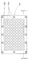
図1は、本発明によるマルチウェル濾過装置の最上部プレート(top plate)1の平面図
を示している。最上部プレート1は、供給部11のための96個の針状漏斗と、抜取り部13のための96個の針状漏斗とを有している。例として、供給部11のための針状漏斗のうちの1つは供給針91を備えており、抜取り部13のための針状漏斗のうちの1つは抜取り針92を備えている。図1では、最上部プレート1の右手側および上部側に、濾過プレート4の上面が見えている。濾過プレート4は、図2および図3中に示されるように
、最上部プレート1の下に配置されている。最上部プレート1、供給部11のための針状漏斗、および、抜取り部13のための針状漏斗は、標準化された96個ウェルマイクロプレートに準拠した構造へと配列されている。
FIG. 1 shows a plan view of a
総じては、標準化されたマイクロプレートに準拠した構造は、標準化された基本的施設(インフラストラクチャー)での当該マルチウェル濾過装置の使用を可能にする。とりわけ、標準化された液体ハンドリングおよび分析機器が使用可能である。 Overall, a standardized microplate compliant structure allows the use of the multiwell filtration device in a standardized infrastructure. In particular, standardized liquid handling and analysis equipment can be used.
次のことは、以降の本記載に適応される。図を明確にするために、図が参照符号を含んでおり、該符号が記載の直接関連する部分に直接されていない場合、それは、それより前の記載部分で言及されている。 The following applies to this description below. For the sake of clarity, if a figure includes a reference number that is not directly directed to a directly related part of the description, it is referred to in the preceding description part.
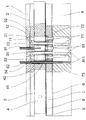
図2および図3は、それぞれ、図1の線A−Aに沿った当該マルチウェル濾過装置の断面図または断面の分解組立図を示している。図1に見られる最上部プレート1に加えて、当該マルチウェル濾過装置は、上部漏斗プレート3と最上部プレート1との間に配置された隔壁2を有する。上部漏斗プレート3に続いて、上部から底部へと、第1のシール(sealing)マット6、濾過プレート4、第2のシールマット6、透明の分離層5、第3のシー
ルマット6、下部漏斗プレート7、第4のシールマット6、および、収集プレート8がある。
2 and 3 respectively show a cross-sectional view or an exploded view of the cross-section of the multiwell filtration device along line AA in FIG. In addition to the
上部漏斗プレート3は、交互に配置された貫通孔を持っており、該貫通孔は、供給部33のためのもの、および、橋渡しチャンネル(bridging channel)31のためのものであり、これらは、圧力等化チャンネル34によって互いに接続されている。上部漏斗プレート3の供給部33のための各貫通孔33は、隔壁2の隔壁開口部21を通って、最上部プレート1の供給部11のための針状漏斗の1つと接続されている。従って、上部漏斗プレート3の各橋渡しチャンネル31は、隔壁2の隔壁開口部21を通って最上部プレート1の抜取りのための針状漏斗13の1つと接続されている。最上部プレート1と、隔壁2と、上部漏斗プレート3との間のピッタリとした接続を提供するために、最上部プレート1は、供給部11のための針状漏斗の周り、および、抜取り13のための針状漏斗の周りに、凹部12を該プレートの下側に有し、かつ、上部漏斗プレート3は、その上側に、供給部33のための貫通孔の周り、および、橋渡しチャンネル31の周りに、尾根状部(ridges)32を有する。接続されるとき、隔壁2は、尾根状部32によって凹部12内へと圧入される。
The
濾過プレート4は、交互に配置された貫通孔を持っており、該貫通孔は、抜取り部42のためのもの、および、濾過チャンバー41のためのものであって、各濾過チャンバー41は、上部漏斗プレート3の供給部33のための貫通孔のうちの1つと接続されている。各橋渡しチャンネル31は、濾過プレート4の抜取り部42のための貫通孔のうちの1つを通って延び、該濾過プレート4の下へと突出している。
The
濾過プレート4は、透明の分離層5に接続され、それがさらにまた下部漏斗プレート7に接続されており、ここで、シールマット6が、透明の分離層5と下部漏斗プレート7との間に配置されている。下部漏斗プレート7は、交互に配置された貫通孔を持っており、該貫通孔は、抜取り部72および濾液漏斗71のためのものであって、各濾液漏斗71は、濾過チャンバーのうちの1つに接続されている。上部漏斗プレート3の各々の橋渡しチャンネル31は、抜取り部72のための貫通孔の1つをさらに通って延びている。
The
各々の濾液漏斗71の上部は、所定の直径の通路を持ったフィルターエレメント73を備えている。該フィルターエレメント73の隣の領域には、透明の分離層5が、孔穴(図には示していない)を有しており、該孔穴は、フィルターエレメント73の通路の直径よ
り大きな直径を有している。好ましくは、各々のフィルターエレメント73は、対応する濾液漏斗71の広がった上部内へ挿入され、かつ、対応する濾液漏斗71の広がった上部で圧縮された、丸い金属メッシュとして配置されている。また、各金属メッシュは、好ましくは、濾液漏斗71の周りで、その横方向端部の区域において裏返されており、結果、該金属メッシュは、下部漏斗プレート7に圧入(press fitted)されている。好ましくは、フィルターエレメントの孔(pore)のサイズは、約1μmから約2μmである。
The upper portion of each
下部漏斗プレート7は、収集プレート8に接続されており、そこでシールマット6が、その間に配置されている。収集プレート8は、丸みをつけた長方形(rounded rectangle)
の形状を有する細長い断面を持った収集ウェル81を有している。前記収集ウェル81の各々は、下部漏斗プレート7の1つの濾液漏斗71に、および、上部漏斗プレート3の1つの橋渡しチャンネルに接続されている。収集ウェル81の底は、わずかに傾斜しており十分に丸みがつけられており、各収集ウェル81は最深部811を有し、該最深部は、前記収集ウェル81に接続されている橋渡しチャンネル31の実質的直下に位置している。
The
The collection well 81 has an elongated cross section having the following shape. Each of the
使用に際しては、濾過チャンバー41のうちの1つに接続されている隔壁開口部21のうちの1つが、供給針91によって貫通されて、該供給針91は前記濾過チャンバー41内へと延びる。図4に最もよく見られるように、供給針91は、隔壁2の隔壁開口部21に適合するためのテーパーになった部分を有する。また使用に際しては、供給針91は、濾過チャンバー41内へ懸濁液を供給し、それによって、該懸濁液をフィルターエレメント73を通過させて収集ウェル81へと運ぶための過圧力(overpressure)を、濾過チャンバー41の内側に作り出す。該過圧力は、供給針91の加圧手段によって提供されることができる。特に、懸濁液が液相としての溶液を有する場合、濾過を行なわせるための過圧の供給は、収集ウェル81内に真空を作ることによって濾過を行なわせることに比べて、懸濁液中の結晶の形成が少ないという利点を有する。それゆえ、同程度の高い濃度の溶質を持ち、邪魔な種(seeds)の無い、濾液を得ることが可能である。
In use, one of the
また、懸濁液中の溶質の高い濃度を得ることを可能にするため、懸濁液と接触する可能性のあるマルチウェル濾過装置の部分は、絶縁材(isolating material)からなるのが好ましく、それによって、高温で濾過された懸濁液の冷却ができる限り低くなる。 Also, in order to be able to obtain a high concentration of solute in the suspension, the part of the multiwell filtration device that may come into contact with the suspension is preferably made of an isolating material, Thereby the cooling of the hot filtered suspension is as low as possible.
濾過チャンバー41への懸濁液の供給を妨げ得る収集ウェル81内側の上昇圧力を防止するために、供給針91は、相応の圧力等化チャンネル92に接続された長手方向の溝を有する。このようにして、収集ウェル81と、当該マルチウェル濾過装置の外側の大気圧との間で、該圧力を等しくすることができる。
In order to prevent the rising pressure inside the collection well 81 which may hinder the supply of suspension to the
フィルターエレメント73は、供給された懸濁液の固体を保持し、該固体は通路を通ることはできない。それによって、濾過ケークが透明の分離層5の上に形成される。透明の分離層5の孔穴の直径は、濾過に実質的に影響しないように十分に大きく、また一方で、濾過ケークを引き止めておくことができるように十分に小さい。
The
収集ウェル81の外へ濾液を抜き取るために、相応の橋渡しチャンネル31に接続されている隔壁開口部21は、抜取り針92によって貫通されており、収集ウェル81の底の最深部811の近傍まで延びている。収集ウェル81の底が少し傾斜しよく丸みを帯びているため、収集ウェル81内の濾液の同様に高いデッドボリューム(無駄な体積)を防止しながら、濾液は効果的に抜き取られる。
In order to withdraw the filtrate out of the collection well 81, the
濾過後、濾過プレート4は、透明の分離層5を用いて、下部漏斗プレート7から容易に分離される。分析すべき結晶または他の固体を含んでいる濾過ケークは、透明の分離層5によって濾過チャンバーの内部にそのまま保持されている。労力を要する準備ステップ無
しに、濾過ケークは、分析機器へ移送されることができ、そして、X線粉末回折、または赤外およびラマン分光法のような適当な分析方法によって、透明の分離層5を通して分析されることができる。
After filtration, the
図5は、シールマット6を受けるための2段(two-step)の階段形態(stair-shaped)とされた高くなった部分(elevation)を示している。2つの層の2つの隣り合った開口部(即
ち、貫通孔、漏斗およびチャンネル)同士の間のシール接続を供給するために、一般的な平らなシールマット6を使用し、2つの開口部のうちの1つの周囲の縁部(border)は、好ましくは、2段の階段形態とされた高くなった部分を有する。シールマット6は、持ち上げられ、シール尾根状部74の頂点に配置され、ガイド尾根状部75に接触している。このようにして、シールマット6は、開口部の周囲で持ち上げられ、そして、2つの層が接続される場合に、該マットは、前記の持ち上げられた領域において圧縮される。
FIG. 5 shows a two-step stair-shaped elevation for receiving the
図6、図7および図8には、移送(transfer)ユニットが、2つの隣り合ったシールマット6と分離層5とを備えた濾過プレート4を有しているのが示されている。上方のシールマット6の上面には、閉鎖層5Aがあり、続いて、最上部プレート1Aが配置されている。それに応じるように、閉鎖層5Bが配置され、続いて、底部プレート1Bが分離層5の下に配置されている。
6, 7 and 8 show that the transfer unit has a
濾過後、2つの隣り合ったシールマット6と分離層5とを一緒に伴った濾過層4は、上記したように、当該マルチウェル濾過装置の残部から容易に分離することができる。濾過プレート4は、閉鎖層5Aおよび5B(それぞれに、最上部プレート1Aまたは底部プレートが続く)によって、上部の表面と同様に、底の表面と同様に、閉鎖することができる。この状態で、最上部プレート1Aは、コンパクトな移送ユニットを形成するために、底部プレート1Bと堅固に接続される。堅固な接続のために、最上部プレート1Aはねじ穴12Aを備え、濾過プレート4はねじ穴43を備え、そして、底部プレート1Bはねじ穴12Bを備え、最上部プレート1Aが、前述のねじ穴12A、43および12Bを貫通するねじを用いて、底部プレート1Bへと堅固に接続され得るようになっている。
After filtration, the
移送ユニットは、濾過プレート4の濾過チャンバー41内に濾過ケークをまだ有しており、それから具合よく移動させ、貯蔵し、相応の分析機器へ移送することができる。好ましくは、上部プレート1Aおよび底部プレート1Bは、貫通孔11Aおよび11Bを備えており、これらは、濾過チャンバー41の隣に配置されており、その上、閉鎖層5Aおよび5Bが透明の材料で作られており、X線粉末回折、または、赤外線およびラマン分光法のような適当な分析方法によって、貫通孔11Aと11Bとを、および、閉鎖層5Aと5Bとを通して、濾過ケークを分析できるようになっている。
The transfer unit still has a filter cake in the
本発明によるマルチウェル濾過装置のその他の代替的な態様が考えられる。これに関して、明確に述べるのは、次のとおりである。
・異なった層の、ウェル、漏斗、および、貫通孔は、他のいかなる適切な構造としても配置することができ、特に、標準化された384個ウェルおよび1536個ウェルのマイクロプレートに準拠した構造として配置することができる。
・移送ユニットは、また、説明した閉鎖層、最上部プレート、および、底部プレートと、その間の濾過プレートの他、他の適当なマルチウェルプレートと共に、形成してよい。
・特に、X線分析に対して好ましくするために、分離層は、アモルファスのフッ素重合体、特に、テフロン(登録商標)AFとしてこの分野の技術者に知られているようなアモルファスのフッ素重合体によって形成してよい。
Other alternative embodiments of the multiwell filtration device according to the invention are conceivable. In this regard, the following is clearly stated.
Different layers of wells, funnels and through-holes can be arranged in any other suitable structure, especially as a structure compliant with standardized 384 well and 1536 well microplates Can be arranged.
The transfer unit may also be formed with other suitable multi-well plates in addition to the described closure layer, top plate, and bottom plate and the filtration plate therebetween.
The separation layer is preferably an amorphous fluoropolymer, in particular an amorphous fluoropolymer as known to those skilled in the art as Teflon AF, in order to be particularly preferred for X-ray analysis. May be formed.
Claims (13)
濾過チャンバー(41)を持った濾過プレート(4)と、
収集ウェル(81)を持った収集プレート(8)とを有し、
濾過チャンバー(41)は、収集ウェル(81)に接続されており、かつ、フィルターエレメント(73)が、濾過チャンバー(41)と収集ウェル(81)との間に配置されており、
濾過プレート(4)と収集プレート(8)との間には、フィルターエレメント(73)の隣に、分離層(5)が配置されていることを特徴とする、
前記マルチウェル濾過装置。 A multiwell filtration device for filtering a suspension,
A filtration plate (4) with a filtration chamber (41);
A collection plate (8) with a collection well (81),
The filtration chamber (41) is connected to the collection well (81), and the filter element (73) is disposed between the filtration chamber (41) and the collection well (81),
Between the filtration plate (4) and the collection plate (8), a separation layer (5) is arranged next to the filter element (73),
The multiwell filtration device.
請求項1〜10のうちの1つのマルチウェル濾過装置を有し、
上昇させた圧力レベルで濾過チャンバー(41)へ懸濁液を供給するための供給針(91)を有し、
収集ウェル(81)の外へ濾液を抜き取るための抜取り針(92)を有し、かつ、
前記マルチウェル濾過装置によって濾過された固相を、該固相が濾過チャンバー(41)内に位置している間に、分離層(5)を通して分析するために配置された、分析装置を有する、
前記システム。 A system for analyzing the solid phase of a suspension,
Having one multiwell filtration device according to claims 1-10,
A supply needle (91) for supplying suspension to the filtration chamber (41) at an elevated pressure level;
Having a withdrawal needle (92) for withdrawing the filtrate out of the collection well (81), and
Having an analytical device arranged to analyze the solid phase filtered by the multiwell filtration device through the separation layer (5) while the solid phase is located in the filtration chamber (41);
Said system.
供給針(91)を用いて、高圧レベルで濾過チャンバー(41)内へ懸濁液を供給し、かつ、それによって、該懸濁液をフィルターエレメント(73)を通して収集ウェル(81)内へ行かせるステップを有し、
収集ウェル(8)から、濾過プレート(4)を、分離層(5)と共に分離するステップを有し、
濾過プレート(4)を、分析装置へと移すステップを有し、かつ、
分離層(5)を通して、固相を分析するステップを有する、
前記方法。 A method for analyzing a solid phase of a suspension using the system according to claim 11 or 12, comprising:
The supply needle (91) is used to supply the suspension into the filtration chamber (41) at a high pressure level, and thereby the suspension is passed through the filter element (73) into the collection well (81). And have a step
Separating the filtration plate (4) together with the separating layer (5) from the collection well (8),
Transferring the filtration plate (4) to the analyzer, and
Analyzing the solid phase through the separation layer (5),
Said method.
Applications Claiming Priority (2)
| Application Number | Priority Date | Filing Date | Title |
|---|---|---|---|
| EP06405198.0 | 2006-05-12 | ||
| EP06405198A EP1854540A1 (en) | 2006-05-12 | 2006-05-12 | Multi-well filtration device |
Related Parent Applications (1)
| Application Number | Title | Priority Date | Filing Date |
|---|---|---|---|
| JP2007125832A Division JP5132984B2 (en) | 2006-05-12 | 2007-05-10 | Multiwell filtration device |
Publications (1)
| Publication Number | Publication Date |
|---|---|
| JP2013010102A true JP2013010102A (en) | 2013-01-17 |
Family
ID=37314076
Family Applications (2)
| Application Number | Title | Priority Date | Filing Date |
|---|---|---|---|
| JP2007125832A Active JP5132984B2 (en) | 2006-05-12 | 2007-05-10 | Multiwell filtration device |
| JP2012144886A Pending JP2013010102A (en) | 2006-05-12 | 2012-06-28 | Multi-well filtration device |
Family Applications Before (1)
| Application Number | Title | Priority Date | Filing Date |
|---|---|---|---|
| JP2007125832A Active JP5132984B2 (en) | 2006-05-12 | 2007-05-10 | Multiwell filtration device |
Country Status (6)
| Country | Link |
|---|---|
| US (1) | US7867452B2 (en) |
| EP (1) | EP1854540A1 (en) |
| JP (2) | JP5132984B2 (en) |
| AT (1) | ATE503579T1 (en) |
| DE (1) | DE602007013487D1 (en) |
| ES (1) | ES2362129T3 (en) |
Families Citing this family (8)
| Publication number | Priority date | Publication date | Assignee | Title |
|---|---|---|---|---|
| EP1854540A1 (en) * | 2006-05-12 | 2007-11-14 | F. Hoffmann-la Roche AG | Multi-well filtration device |
| EP2144843B1 (en) * | 2007-05-15 | 2019-10-23 | Wako Pure Chemical Industries, Ltd. | Method of controlling pressure in a microfluidic device |
| US20130180171A1 (en) * | 2012-01-13 | 2013-07-18 | Kevin Oldenburg | Systems and Methods for Harvesting and/or Analyzing Biological Samples |
| EP2895269A1 (en) * | 2012-09-11 | 2015-07-22 | Centre Hospitalier Universitaire Vaudois | Conical multi-well filter plate |
| US9568404B2 (en) | 2014-05-16 | 2017-02-14 | Junyu Mai | Method and apparatus for biomolecule analysis |
| JP6606352B2 (en) * | 2015-05-27 | 2019-11-13 | 国立大学法人 香川大学 | Determination method of ethanol and glucose in moromi and filtration device |
| CN114247484B (en) * | 2020-09-24 | 2023-06-23 | 京东方科技集团股份有限公司 | Microfluidic device and microfluidic system |
| CN113274784B (en) * | 2021-06-01 | 2022-10-18 | 广州市朔康医疗科技有限公司 | Intelligent medical wastewater filter |
Citations (9)
| Publication number | Priority date | Publication date | Assignee | Title |
|---|---|---|---|---|
| JPH02187110A (en) * | 1988-09-16 | 1990-07-23 | W R Grace & Co | Micro-filtration apparatus and its method |
| JPH04227032A (en) * | 1990-07-18 | 1992-08-17 | Bio Rad Lab Inc | Multi-sample filter plate assembling device |
| JP2002528265A (en) * | 1998-10-29 | 2002-09-03 | ピーイー コーポレイション (エヌワイ) | Multiwell microfiltration device |
| JP2004526950A (en) * | 2001-01-23 | 2004-09-02 | ヴァリアン インコーポレーテッド | Multiwell filtration device |
| JP2005017287A (en) * | 2003-06-24 | 2005-01-20 | Millipore Corp | Multifunctional vacuum manifold |
| JP2005516200A (en) * | 2002-01-31 | 2005-06-02 | ヴァリアン インコーポレーテッド | One-way flow control sealing mat for well plates |
| JP2005148048A (en) * | 2003-04-25 | 2005-06-09 | Jsr Corp | Biochip, biochip kit, and method for manufacturing and using the same |
| JP2005214964A (en) * | 2003-12-12 | 2005-08-11 | Becton Dickinson & Co | Method for attaching membrane |
| JP5132984B2 (en) * | 2006-05-12 | 2013-01-30 | エフ.ホフマン−ラ ロシュ アーゲー | Multiwell filtration device |
Family Cites Families (11)
| Publication number | Priority date | Publication date | Assignee | Title |
|---|---|---|---|---|
| US5674395A (en) * | 1995-06-05 | 1997-10-07 | Millipore Corporation | Multiple sample separator |
| US5958714A (en) * | 1996-10-02 | 1999-09-28 | Safety Associates, Inc. | Test kits for determining at least two specific analytes in foods and other complex matrices |
| US5972694A (en) | 1997-02-11 | 1999-10-26 | Mathus; Gregory | Multi-well plate |
| US5888831A (en) * | 1997-03-05 | 1999-03-30 | Gautsch; James W. | Liquid-sample-separation laboratory device and method particularly permitting ready extraction by syringe of the separated liquid sample |
| US6716396B1 (en) * | 1999-05-14 | 2004-04-06 | Gen-Probe Incorporated | Penetrable cap |
| WO2001019520A1 (en) * | 1999-09-13 | 2001-03-22 | Millipore Corporation | High density cast-in-place sample preparation card |
| US6750064B2 (en) * | 2000-12-28 | 2004-06-15 | S.S.C.I. Inc. | Methods of screening for possible solid forms |
| US6939515B2 (en) * | 2001-08-10 | 2005-09-06 | Symyx Technologies, Inc. | Apparatuses and methods for creating and testing pre-formulations and systems for same |
| US20040089615A1 (en) * | 2002-11-12 | 2004-05-13 | Alan Weiss | Evaporation control device for multiwell plates |
| CA2467131C (en) | 2003-05-13 | 2013-12-10 | Becton, Dickinson & Company | Method and apparatus for processing biological and chemical samples |
| EP1854542B1 (en) * | 2006-05-12 | 2011-03-30 | F. Hoffmann-La Roche AG | Multi-well filtration device |
-
2006
- 2006-05-12 EP EP06405198A patent/EP1854540A1/en not_active Withdrawn
-
2007
- 2007-05-07 ES ES07107643T patent/ES2362129T3/en active Active
- 2007-05-07 DE DE602007013487T patent/DE602007013487D1/en active Active
- 2007-05-07 AT AT07107643T patent/ATE503579T1/en not_active IP Right Cessation
- 2007-05-09 US US11/801,661 patent/US7867452B2/en active Active
- 2007-05-10 JP JP2007125832A patent/JP5132984B2/en active Active
-
2012
- 2012-06-28 JP JP2012144886A patent/JP2013010102A/en active Pending
Patent Citations (9)
| Publication number | Priority date | Publication date | Assignee | Title |
|---|---|---|---|---|
| JPH02187110A (en) * | 1988-09-16 | 1990-07-23 | W R Grace & Co | Micro-filtration apparatus and its method |
| JPH04227032A (en) * | 1990-07-18 | 1992-08-17 | Bio Rad Lab Inc | Multi-sample filter plate assembling device |
| JP2002528265A (en) * | 1998-10-29 | 2002-09-03 | ピーイー コーポレイション (エヌワイ) | Multiwell microfiltration device |
| JP2004526950A (en) * | 2001-01-23 | 2004-09-02 | ヴァリアン インコーポレーテッド | Multiwell filtration device |
| JP2005516200A (en) * | 2002-01-31 | 2005-06-02 | ヴァリアン インコーポレーテッド | One-way flow control sealing mat for well plates |
| JP2005148048A (en) * | 2003-04-25 | 2005-06-09 | Jsr Corp | Biochip, biochip kit, and method for manufacturing and using the same |
| JP2005017287A (en) * | 2003-06-24 | 2005-01-20 | Millipore Corp | Multifunctional vacuum manifold |
| JP2005214964A (en) * | 2003-12-12 | 2005-08-11 | Becton Dickinson & Co | Method for attaching membrane |
| JP5132984B2 (en) * | 2006-05-12 | 2013-01-30 | エフ.ホフマン−ラ ロシュ アーゲー | Multiwell filtration device |
Also Published As
| Publication number | Publication date |
|---|---|
| JP2008000744A (en) | 2008-01-10 |
| DE602007013487D1 (en) | 2011-05-12 |
| EP1854540A1 (en) | 2007-11-14 |
| US20070264163A1 (en) | 2007-11-15 |
| ES2362129T3 (en) | 2011-06-28 |
| US7867452B2 (en) | 2011-01-11 |
| ATE503579T1 (en) | 2011-04-15 |
| JP5132984B2 (en) | 2013-01-30 |
Similar Documents
| Publication | Publication Date | Title |
|---|---|---|
| JP2013010102A (en) | Multi-well filtration device | |
| EP0591436B1 (en) | System for growing and manipulating tissue cultures | |
| JP6666313B2 (en) | Connectors for pneumatic devices in microfluidic systems | |
| DE4127276C2 (en) | Device and method for separating liquid samples | |
| EP3039118B1 (en) | Exposure apparatus | |
| KR101995767B1 (en) | Systems and devices for sample handling | |
| US20070284300A1 (en) | Removing material from liquid sample within a sample vessel | |
| EP1724019B1 (en) | Receiver plate with multiple cross-sections | |
| JP2005516200A (en) | One-way flow control sealing mat for well plates | |
| EP1854542B1 (en) | Multi-well filtration device | |
| JP2013513097A (en) | Method and system for processing a sample on a porous substrate | |
| EP0871544B1 (en) | Multiple sample filtration device | |
| DE102014004851A1 (en) | Vertical functional reaction vessel | |
| EP2758764B1 (en) | Solid phase extraction device for dried sample cards | |
| EP1397212B1 (en) | Positioning pins for multiwell test apparatus | |
| KR100812728B1 (en) | Multi-well filter plate with shifted wells and u-bottom receiver plate | |
| US20200292426A1 (en) | System and method for filtering samples from vessels | |
| US20050095175A1 (en) | Support and stand-off ribs for underdrain for multi-well device | |
| US11541353B2 (en) | Container and method for filtering a suspension | |
| WO2003103812A1 (en) | Modular system for separating components of a liquid sample | |
| JP2007306925A (en) | Elastomer device for sowing cell on filter bottom | |
| DE10329983A1 (en) | Micro-reactor module allows multiple different reactions to be performed simultaneously and to be serviced by a standard automatic micro-titer head, is formed of a multiple recessed base plate which is sealed by a releasable cover plate | |
| CN212871934U (en) | Porous plate filtering device | |
| US20090155920A1 (en) | High throughput dissolution and precipitation apparatus and method | |
| CN112067412A (en) | Multi-well plate filtration device and method |
Legal Events
| Date | Code | Title | Description |
|---|---|---|---|
| A131 | Notification of reasons for refusal |
Free format text: JAPANESE INTERMEDIATE CODE: A131 Effective date: 20130806 |
|
| A02 | Decision of refusal |
Free format text: JAPANESE INTERMEDIATE CODE: A02 Effective date: 20140212 |