JP2013000968A - Recording apparatus, control method for recording apparatus and program - Google Patents
Recording apparatus, control method for recording apparatus and program Download PDFInfo
- Publication number
- JP2013000968A JP2013000968A JP2011133940A JP2011133940A JP2013000968A JP 2013000968 A JP2013000968 A JP 2013000968A JP 2011133940 A JP2011133940 A JP 2011133940A JP 2011133940 A JP2011133940 A JP 2011133940A JP 2013000968 A JP2013000968 A JP 2013000968A
- Authority
- JP
- Japan
- Prior art keywords
- recording medium
- recording
- cover
- detection
- detection means
- Prior art date
- Legal status (The legal status is an assumption and is not a legal conclusion. Google has not performed a legal analysis and makes no representation as to the accuracy of the status listed.)
- Pending
Links
Images


Abstract
Description
本発明は、記録装置、記録装置の制御方法、及び、プログラムに関する。 The present invention relates to a recording apparatus, a control method for the recording apparatus, and a program.
従来、ロール紙等の記録媒体を、カバーを有する本体に収容し記録媒体に記録を行うとともにオートカッターでカット処理を行い単票として発行する記録装置が知られている。この種の記録装置は、記録した位置に合わせて記録媒体のカット処理を行うため、記録媒体の位置合わせを行う必要がある。このため、記録媒体には、例えばブラックマークと呼ばれる位置検出用マークが設けられており、記録装置は、位置検出用マークを検出する検出手段を備えている。そして、検出された位置検出用マークの位置を基準として記録やカット等の処理が行われる(例えば、特許文献1参照)。 2. Description of the Related Art Conventionally, there is known a recording apparatus that stores a recording medium such as roll paper in a main body having a cover, performs recording on the recording medium, performs cut processing with an auto cutter, and issues it as a single sheet. Since this type of recording apparatus performs the cutting process of the recording medium in accordance with the recorded position, it is necessary to align the recording medium. For this reason, the recording medium is provided with, for example, a position detection mark called a black mark, and the recording apparatus is provided with detection means for detecting the position detection mark. Then, processing such as recording and cutting is performed based on the position of the detected position detection mark (see, for example, Patent Document 1).
位置検出用マークが付いた記録媒体に記録を行う記録装置では、記録媒体の交換時に記録媒体の位置検出用マークがどこにあるのか不明になる(記録媒体の位置が不明になる)ので、記録媒体の位置検出用マークを検出し、これに基づき記録媒体を初期位置に位置決めする必要がある。そのために、従来においては、記録媒体の紙送り動作を行って位置検出用マークを検出し、これに基づき、記録媒体をカッターによる切断位置に位置決めして先頭側の部分をカットすることにより、記録媒体を初期位置に位置決めしている。 In a recording apparatus that performs recording on a recording medium with a position detection mark, it is unclear where the recording medium position detection mark is located when the recording medium is replaced (the position of the recording medium is unknown). It is necessary to detect the position detection mark and position the recording medium at the initial position based on the detected position detection mark. Therefore, conventionally, the recording medium is fed to detect the position detection mark, and based on this, the recording medium is positioned at the cutting position by the cutter, and the head portion is cut, thereby recording the recording medium. The medium is positioned at the initial position.
記録媒体の交換を示す指標として記録装置のカバーの開閉を検出して上記の位置決め動作を行う場合がある。このとき、単にカバーが開閉されたのみで記録媒体が交換されない場合は、記録媒体の位置がずれる可能性がある。特に、サーマル方式のプリンターは、カバー側に設けられたプラテンと本体側に設けられたサーマルヘッドにより、カバーを閉めると記録媒体が挟持される構成となっている。このようなプリンターでは、記録媒体を交換する場合でなくても、カバーを開けると挟持されていた記録媒体が開放されて位置がずれてしまい、その状態でカバーを締めると記録媒体の位置がずれて挟持される。 In some cases, the positioning operation is performed by detecting the opening and closing of the cover of the recording apparatus as an index indicating the replacement of the recording medium. At this time, if the recording medium is not replaced simply by opening and closing the cover, the position of the recording medium may be shifted. In particular, a thermal printer has a configuration in which a recording medium is sandwiched when a cover is closed by a platen provided on the cover side and a thermal head provided on the main body side. In such a printer, even if the recording medium is not replaced, if the cover is opened, the sandwiched recording medium is released and the position is shifted, and if the cover is tightened in this state, the position of the recording medium is shifted. It is pinched.
そのため、カット動作により小さな紙片が発生し、紙ジャムの原因となる虞がある。または、記録媒体がオートカッターの位置になくてカットしてしまう、いわゆる空カットを行うことにより、カッター寿命を縮める原因となる虞がある。 Therefore, a small piece of paper is generated by the cutting operation, which may cause a paper jam. Alternatively, performing the so-called empty cut that cuts the recording medium without being at the position of the auto cutter may cause a shortened cutter life.
本発明は、上述の課題の少なくとも一部を解決するためになされたものであり、以下の形態または適用例として実現することが可能である。 SUMMARY An advantage of some aspects of the invention is to solve at least a part of the problems described above, and the invention can be implemented as the following forms or application examples.
(適用例1)搬送手段で搬送される記録媒体に対して、記録手段で情報を記録し単票として発行する記録装置であって、前記記録媒体を収容するカバー付きの収容部と、前記カバーの開閉状態を検出するカバー開閉検出手段と、前記収容部に収容される前記記録媒体の残量が所定の量以下になったことを検出するニアーエンド検出手段と、前記記録媒体の搬送経路上に設けられ、前記記録媒体上に搬送方向に沿って所定間隔で設けられている位置検出用マークを検出するマーク検出手段と、前記搬送手段によって搬送される前記記録媒体を所定の位置に合わせる位置合わせ手段と、前記搬送手段により前記記録媒体が搬送される搬送経路上に設けられ、前記記録媒体をカットするカット手段と、を備え、前記カバー開閉検出手段及び前記ニアーエンド検出手段の検出状態に基づいて、前記マーク検出手段の検出結果を用いて、前記位置合わせ手段による前記記録媒体の位置合わせ、及び/または、前記カット手段による前記記録媒体のカット、を実施することを特徴とする記録装置 (Application Example 1) A recording apparatus that records information by a recording unit and issues it as a single sheet with respect to a recording medium conveyed by a conveying unit, and a storage unit with a cover that stores the recording medium, and the cover A cover open / close detecting means for detecting the open / closed state of the recording medium; a near end detecting means for detecting that the remaining amount of the recording medium accommodated in the accommodating portion is equal to or less than a predetermined amount; and a transport path for the recording medium. A mark detecting means for detecting position detection marks provided at predetermined intervals along the transport direction on the recording medium, and alignment for aligning the recording medium transported by the transport means with a predetermined position And a cutting means for cutting the recording medium provided on a conveying path along which the recording medium is conveyed by the conveying means, the cover open / close detecting means and the near Based on the detection state of the end detection unit, the recording medium is aligned by the alignment unit and / or the recording medium is cut by the cutting unit using the detection result of the mark detection unit. Recording apparatus characterized by that
この構成によれば、記録装置は、記録媒体が収容される収容部のカバーの開閉状態及び記録媒体の残量が所定の量以下になったこと、すなわちニアーエンド状態の変化を検出することができる。そしてこれらの検出結果から記録媒体が交換されたか否かを検知することができる。記録媒体が交換された場合には、記録媒体に設けられた位置検出用マークを検出することによって、記録媒体の位置合わせ及びカットを行うことができる。また、記録媒体が交換されない場合には、カット動作を行わず記録媒体の位置合わせを行うことができる。そのため、無駄なカット動作を防止することができ、作業の効率化、紙ジャム等の不具合の低減、及び信頼性の向上を実現できる。 According to this configuration, the recording apparatus can detect the open / close state of the cover of the storage unit in which the recording medium is accommodated and that the remaining amount of the recording medium is equal to or less than the predetermined amount, that is, a change in the near-end state. . From these detection results, it can be detected whether or not the recording medium has been replaced. When the recording medium is exchanged, the recording medium can be aligned and cut by detecting a position detection mark provided on the recording medium. If the recording medium is not exchanged, the recording medium can be aligned without performing the cutting operation. Therefore, useless cutting operation can be prevented, work efficiency can be improved, defects such as paper jam can be reduced, and reliability can be improved.
(適用例2)前記カバーを閉めたとき前記記録媒体を挟持し、前記カバーを開いたとき前記記録媒体を開放するもので、一方が前記カバー側に設けられ、他方が本体側に設けられた挟持手段を有することを特徴とする上記の記録装置。 (Application example 2) The recording medium is sandwiched when the cover is closed, and the recording medium is opened when the cover is opened. One is provided on the cover side and the other is provided on the main body side. The recording apparatus as described above, further comprising a clamping unit.
(適用例3)前記挟持手段は、サーマルヘッドとプラテンとで構成されることを特徴とする上記の記録装置。 (Application Example 3) The recording apparatus described above, wherein the clamping means is composed of a thermal head and a platen.
これらの構成によれば、カバーの開閉によって記録媒体がずれ易いサーマルプリンターであっても、確実に記録媒体の位置合わせを行うことができる。また、無駄なカット動作を防止することができ、作業の効率化、紙ジャム等の不具合の低減、及び信頼性の向上を実現できる。 According to these configurations, the recording medium can be reliably aligned even in a thermal printer in which the recording medium is easily displaced by opening and closing the cover. In addition, useless cutting operations can be prevented, work efficiency can be improved, defects such as paper jam can be reduced, and reliability can be improved.
(適用例4)前記カバー開閉検出手段が前記カバーの開閉を検知し、かつ、前記ニアーエンド検出手段が前記記録媒体のニアーエンド状態を検出し、その後、非ニアーエンド状態を検出したときは、前記記録媒体は交換されたと判断して、前記マーク検出手段の検出結果を用いて、前記位置合わせ手段による前記記録媒体の位置合わせ、及び、前記カット手段による前記記録媒体のカットを実施することを特徴とする上記の記録装置。 Application Example 4 When the cover opening / closing detection unit detects opening / closing of the cover, and the near-end detection unit detects a near-end state of the recording medium, and then detects a non-near-end state, the recording medium Is determined to have been replaced, and using the detection result of the mark detection means, the alignment of the recording medium by the alignment means and the cutting of the recording medium by the cutting means are performed. The recording device described above.
この構成によれば、記録装置は、記録媒体が交換されたと判断して記録媒体の位置合わせ及びカット動作を行うことができる。 According to this configuration, the recording apparatus can determine that the recording medium has been replaced and perform alignment and cutting operations of the recording medium.
(適用例5)前記カバー開閉検出手段が前記カバーの開閉を検知したが、前記ニアーエンド検出手段が前記記録媒体のニアーエンド状態を検出しないときは、前記記録媒体は交換されてないと判断して、前記マーク検出手段の検出結果を用いて、前記位置合わせ手段による前記記録媒体の位置合わせを実施し、前記カット手段による前記記録媒体のカットを実施しないことを特徴とする上記の記録装置。 (Application Example 5) When the cover open / close detection unit detects the opening / closing of the cover, but the near end detection unit does not detect the near end state of the recording medium, it is determined that the recording medium is not replaced, The recording apparatus according to claim 1, wherein the position of the recording medium is adjusted by the positioning means using the detection result of the mark detecting means, and the recording medium is not cut by the cutting means.
この構成によれば、記録装置は、記録媒体が交換されなかったと判断して記録媒体の位置合わせのみを実施し、カット動作を省略することができる。 According to this configuration, the recording apparatus can determine that the recording medium has not been replaced, perform only the alignment of the recording medium, and omit the cutting operation.
(適用例6)搬送手段で搬送される記録媒体に対して、記録手段で情報を記録し単票として発行する記録装置の制御方法であって、前記記録装置は、前記記録媒体を収容するカバー付きの収容部と、前記カバーの開閉状態を検出するカバー開閉検出手段と、前記収容部に収容される前記記録媒体の残量が所定の量以下になったことを検出するニアーエンド検出手段と、前記記録媒体の搬送経路上に設けられ、前記記録媒体上に搬送方向に沿って所定間隔で設けられている位置検出用マークを検出するマーク検出手段と、前記搬送手段によって搬送される前記記録媒体を所定の位置に合わせる位置合わせ手段と、前記搬送手段により前記記録媒体が搬送される搬送経路上に設けられ、前記記録媒体をカットするカット手段と、を備え、前記カバー開閉検出手段及び前記ニアーエンド検出手段の検出状態に基づいて、前記マーク検出手段の検出結果を用いて、前記位置合わせ手段による前記記録媒体の位置合わせ、及び/または、前記カット手段による前記記録媒体のカットを実施することを特徴とする記録装置の制御方法。 Application Example 6 A method for controlling a recording apparatus that records information by a recording unit and issues it as a single sheet with respect to a recording medium conveyed by a conveying unit, and the recording apparatus covers a recording medium An attached storage section, a cover open / close detection means for detecting an open / closed state of the cover, a near-end detection means for detecting that the remaining amount of the recording medium stored in the storage section is a predetermined amount or less, Mark detection means for detecting position detection marks provided on the recording medium at predetermined intervals along the conveyance direction, and the recording medium conveyed by the conveyance means Positioning means for aligning the recording medium with a predetermined position, and cutting means provided on a transport path along which the recording medium is transported by the transporting means, and for cutting the recording medium. Based on the detection state of the open / close detection means and the near-end detection means, the detection result of the mark detection means is used to align the recording medium by the alignment means and / or the recording medium by the cut means. A control method for a recording apparatus, wherein the cutting is performed.
この制御方法によれば、記録装置は、記録媒体が収容される収容部のカバーの開閉状態及び記録媒体の残量が所定の量以下になったこと、すなわちニアーエンド状態の変化を検出することができる。そしてこれらの検出結果から記録媒体が交換されたか否かを検知することができる。記録媒体が交換された場合には、記録媒体に設けられた位置検出用マークを検出することによって、記録媒体の位置合わせ及びカットを行うことができる。また、記録媒体が交換されない場合には、カット動作を行わず記録媒体の位置合わせを行うことができる。そのため、無駄なカット動作を防止することができ、作業の効率化、紙ジャム等の不具合の低減、及び信頼性の向上を実現できる。 According to this control method, the recording apparatus can detect the open / close state of the cover of the storage unit in which the recording medium is stored and the remaining amount of the recording medium have become equal to or less than a predetermined amount, that is, a change in the near-end state. it can. From these detection results, it can be detected whether or not the recording medium has been replaced. When the recording medium is exchanged, the recording medium can be aligned and cut by detecting a position detection mark provided on the recording medium. If the recording medium is not exchanged, the recording medium can be aligned without performing the cutting operation. Therefore, useless cutting operation can be prevented, work efficiency can be improved, defects such as paper jam can be reduced, and reliability can be improved.
(適用例7)記録媒体を搬送する搬送手段と、前記記録媒体に情報を記録する記録手段と、前記記録媒体を収容するカバー付きの収容部と、前記カバーの開閉状態を検出するカバー開閉検出手段と、前記収容部に収容される前記記録媒体の残量が所定の量以下になったことを検出するニアーエンド検出手段と、前記記録媒体の搬送経路上に設けられ、前記記録媒体上に搬送方向に沿って所定間隔で設けられている位置検出用マークを検出するマーク検出手段と、前記搬送手段によって搬送される前記記録媒体を所定の位置に合わせる位置合わせ手段と、前記搬送手段により前記記録媒体が搬送される搬送経路上に設けられ、前記記録媒体をカットするカット手段と、を備えた記録装置を制御する制御部が実行可能なプログラムであって、前記カバー開閉検出手段及び前記ニアーエンド検出手段の検出状態に基づいて、前記マーク検出手段の検出結果を用いて、前記位置合わせ手段による前記記録媒体の位置合わせ、及び/または、前記カット手段による前記記録媒体のカットを実施することを特徴とする制御部が実行可能なプログラム。 Application Example 7 Conveying means for conveying a recording medium, recording means for recording information on the recording medium, an accommodating portion with a cover for accommodating the recording medium, and cover opening / closing detection for detecting the open / closed state of the cover Means, a near-end detecting means for detecting that the remaining amount of the recording medium accommodated in the accommodating portion is equal to or less than a predetermined amount, and a conveying path for the recording medium provided on the recording medium. Mark detecting means for detecting position detection marks provided at predetermined intervals along the direction, positioning means for aligning the recording medium conveyed by the conveying means to a predetermined position, and recording by the conveying means A program that can be executed by a control unit that controls a recording apparatus that includes a cutting unit that is provided on a conveyance path through which the medium is conveyed, and cuts the recording medium, Based on the detection state of the bar opening / closing detection means and the near end detection means, the detection result of the mark detection means is used to align the recording medium by the alignment means and / or the recording medium by the cutting means. A program that can be executed by the control unit, which is characterized by performing the above-described cutting.
このプログラムを制御部が実行することによって、記録装置は、記録媒体が収容される収容部のカバーの開閉状態及び記録媒体の残量が所定の量以下になったこと、すなわちニアーエンド状態の変化を検出することができる。そしてこれらの検出結果から記録媒体が交換されたか否かを検知することができる。記録媒体が交換された場合には、記録媒体に設けられた位置検出用マークを検出することによって、記録媒体の位置合わせ及びカットを行うことができる。また、記録媒体が交換されない場合には、カット動作を行わず記録媒体の位置合わせを行うことができる。そのため、無駄なカット動作を防止することができ、作業の効率化、紙ジャム等の不具合の低減、及び信頼性の向上を実現できる。 By executing this program by the control unit, the recording device can detect whether the cover of the storage unit in which the recording medium is stored and the remaining amount of the recording medium are below a predetermined amount, that is, the change in the near-end state. Can be detected. From these detection results, it can be detected whether or not the recording medium has been replaced. When the recording medium is exchanged, the recording medium can be aligned and cut by detecting a position detection mark provided on the recording medium. If the recording medium is not exchanged, the recording medium can be aligned without performing the cutting operation. Therefore, useless cutting operation can be prevented, work efficiency can be improved, defects such as paper jam can be reduced, and reliability can be improved.
以下、本発明の実施形態について、図面を参照して説明する。なお、以下の各図においては、説明を簡便にするため、各部の詳細構造や尺度を実際とは異ならせしめている。 Hereinafter, embodiments of the present invention will be described with reference to the drawings. In the following drawings, the detailed structure and scale of each part are different from actual ones for the sake of simplicity.
(印刷システムの構成について)
本発明の実施形態に係る記録装置としてのプリンターを適用した印刷システムについて図1を参照して説明する。図1は、本発明の実施形態に係るプリンターを適用した印刷システムの概略構成を示す図である。
(About the configuration of the printing system)
A printing system to which a printer as a recording apparatus according to an embodiment of the present invention is applied will be described with reference to FIG. FIG. 1 is a diagram illustrating a schematic configuration of a printing system to which a printer according to an embodiment of the present invention is applied.
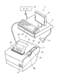
図1に示すように、印刷システム1は、単票としての帳票10を発行するプリンター2に、プリンター2を制御するホストコンピューター3を接続して構成される。図1に示す印刷システム1は、例えば小売店等の店頭に設置された販売時点管理システム(POSシステム)のレジスター、或いは、冨くじや各種チケットを発券する発券システムを構成し、レシート、クーポン、くじ、チケット等の帳票10を印刷して発行する。
As shown in FIG. 1, a printing system 1 is configured by connecting a
ホストコンピューター3は、売上登録処理や精算処理の処理内容、或いは発行する帳票に関する情報を表示するディスプレイ12、帳票発行に関するバーコードを読み取るバーコードスキャナー13、帳票発行指示等のキー等の各種キーを備えたキー入力部14、精算用の現金を収容するキャッシュドロワー15等を備えている。また、ホストコンピューター3には、プリンター2による帳票10の発行記録や取引記録のデータを収集するサーバー16が接続されている。
The
帳票10の発行に際し、ホストコンピューター3は、バーコードスキャナー13からの入力値や、キー入力部14からの入力値に基づいて、サーバー16にアクセスし、帳票10を発行するために必要な情報を取得し、プリンター2に帳票10の発行に係る各種動作を行わせる制御データを生成し、プリンター2に出力する。プリンター2は、ホストコンピューター3から入力された制御データに基づいて、各部を動作させ、帳票10を発行する。
When the
(記録装置の構成について)
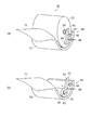
本発明の実施形態に係る記録装置としてのプリンターについて図1〜図3を参照して説明する。図2は、印刷システムが備えるプリンターの要部構成を示す側面図である。図3は、ニアーエンド検出手段を説明する図であり、(a)は、ニアーエンド不検出状態を表す図、(b)は、ニアーエンド不検出状態を表す図である。
(About the configuration of the recording device)
A printer as a recording apparatus according to an embodiment of the present invention will be described with reference to FIGS. FIG. 2 is a side view illustrating a main configuration of a printer included in the printing system. FIGS. 3A and 3B are diagrams for explaining the near-end detection means. FIG. 3A is a diagram showing a near-end non-detection state, and FIG. 3B is a diagram showing a near-end non-detection state.
図1に示すように、プリンター2の本体20には開閉可能なカバー35が設けられる。本体20には、カバー35を開くためのレバー36が設けられ、カバー35を開くと、記録媒体としてのロール紙22を収容する収容部70が露出し、ロール紙22の補充や交換が可能になる。カバー35には、カバー35の開閉状態を検知するカバー開閉検出手段としてのカバーセンサー61(図5参照)が設けられている。また、本体20には、プリンター2の電源をオン/オフさせる電源スイッチ37、動作モードの切り替え等の操作を行うための紙送りスイッチ38、及び、LEDの点灯/消灯状態によりプリンター2の動作状態等を表示するLED表示部39が設けられている。
As shown in FIG. 1, the
図2に示すように、プリンター2は、長尺の感熱紙をロール状に巻いたロール紙22を記録媒体として用い、サーマルヘッド24によりロール紙22に熱を加えて文字等を記録(印刷)する。印刷後のロール紙22はカット手段としてのカッターユニット25によってカットされ、帳票10として図1に示す排紙口28から排出される。プリンター2は、本体20にロール紙22を収容し、このロール紙22を繰り出して搬送するローラー形状のプラテン23(搬送手段)と、プラテン23に対向配置されたサーマルヘッド24と、搬送方向に対し直交する方向にロール紙22をカットするカッターユニット25とを備える。カッターユニット25は、ロール紙22を幅方向に完全にカットする構成であっても、幅方向中央または端部を切り残す構成であってもよい。
As shown in FIG. 2, the
プラテン23は、図示しない駆動機構を介して搬送モーター33(図5参照)に連結されており、搬送モーター33の動作により回転する。プラテン23とサーマルヘッド24とは板ばね等の付勢手段により相互に密接するよう付勢されている。また、プラテン23の周面はゴム等を用いて摩擦係数の高い面となっている。このため、プラテン23の回転に伴い、プラテン23とサーマルヘッド24との間に挟まれたロール紙22が搬送される。搬送モーター33が正方向に回転する場合、プラテン23はロール紙22を排紙口28に向けて搬送する方向に回転する。この場合の搬送方向を正方向とし、図2に矢印Fで示す。反対に、搬送モーター33が逆方向に回転する場合、プラテン23はロール紙22を排紙口28から引き戻す方向に回転する。この場合の搬送方向を逆方向とする。
The
ロール紙22は、少なくとも一方の面に熱によって発色する発色層が設けられ、この面が表面10A(記録面)となっている。表面10Aの反対側、即ち裏面10Bには、印刷やカットの位置合わせのために、位置検出用マークとしてのブラックマークBM(図4参照)が所定間隔で設けられている。なお、裏面10Bにおける発色層の有無は問わない。
The
ブラックマークBMは、例えば裏面10Bの幅方向の一端に形成された所定サイズのマークであり、例えば、搬送方向に沿ったサイズが五ミリ程度の長方形である。ブラックマークBMの色としては、白色のロール紙22に黒いブラックマークBMが形成される態様が一般的であるが、後述するマーク検出手段としてのBMセンサー64のような光センサーが検出可能であればよい。ブラックマークBMは、ロール紙22の全長にわたって、所定長さ毎に、即ち等間隔で印刷等により形成されている。なお、ブラックマークBM付きの帳票10の詳細については後述する。
The black mark BM is, for example, a mark having a predetermined size formed at one end in the width direction of the
次いで、ロール紙22が収容される収容部70及びニアーエンド検出手段80について説明する。図3に示すように、収容部70は、ロール紙保持面72と、ニアーエンド検出手段80とを備える。ロール紙22は、収容部70のロール紙保持面72に回転自在に保持、収容される。ニアーエンド検出手段80は、ロール紙22のロール状をなす側面側にニアーエンドレバー81を有する。ニアーエンドレバー81は、ニアーエンドレバー回転中心82を中心にして回転自在であり、ニアーエンドレバー回転中心82から図中下方向へ延在し、延在した他端に検出突起84を有する。そして、ニアーエンド検出手段80は、検出突起84をロール紙22へ押圧状態にするばね85と、ニアーエンドレバー81の回動に連動して電気的にオン、オフするメカスイッチ86とを有する。
Next, the
このような構成のニアーエンド検出手段80において、使用前のロール紙22が投げ込み方式により装着されると、図3(a)に示すように、検出突起84がロール紙22側面に押されて回動し、メカスイッチ86を電気的オン状態に作動させる。メカスイッチ86の作動により、ロール紙22が装着され供給可能であることが検出される。印刷が行われロール紙22が消費されロール径が小さくなると、図3(b)に示すように、ロール紙芯83が次第に下方に下がり、検出突起84の位置へ移動して来る。ロール紙22に巻かれている帳票10が規定量以下になると、ばね85の押圧によりロール紙芯83の中空部分へ検出突起84が入り込む。検出突起84が中空部分へ入り込むと、ニアーエンドレバー81は回動しメカスイッチ86から離れる。そのため、メカスイッチ86は、電気的にオフとなりロール紙22が所定に残量以下となる、ニアーエンド状態であることが検出される。
In the near-end detecting means 80 having such a configuration, when the
なお、ロール紙22が軸支方式であっても、ロール紙22のニアーエンド検出は可能である。軸支方式の場合、ロール紙22は、ロール紙芯83の中空部分を軸支される。この軸支部にニアーエンド検出手段80が構成される。使用前のロール紙22を設置したとき、ニアーエンド検出手段80は、検出突起84がロール紙22の側面部に接する状態となっている。ロール紙22が消費されると、軸支される中空部分を中心にしてロール径が次第に小さくなり、検出突起84がロール紙22の側面部に接する状態から外れ、ばね85の押圧によりメカスイッチ86から離れる方向へ回動する。そのため、メカスイッチ86は、電気的にオフとなりニアーエンド状態を検出する。投げ込み方式及び軸支方式のいずれにおいても、検出突起84の位置を変えることによりニアーエンド状態でのロール紙22の残量を任意に設定可能である。
Note that even if the
図2に示すように、プリンター2は、ロール紙22の表面10Aに接するようにサーマルヘッド24が配置され、裏面10Bに対向してBMセンサー64(マーク検出手段)が設けられている。BMセンサー64は、例えば反射型の光センサーであり、裏面10Bに対して光を照射し、その反射光の光量を検出する。このBMセンサー64が検出した光量の変化に基づきブラックマークBMを検出できる。
As shown in FIG. 2, in the
また、カッターユニット25は、ロール紙22の搬送路の一方側(裏面10B側)に配置された固定刃30と、この固定刃30に対向してロール紙22の搬送路の他方側(表面10A側)に配置された可動刃31と、可動刃31を固定刃30に向けてスライドさせるカッター駆動モーター32とを備えている。カッター駆動モーター32の駆動力により、駆動機構(図示略)を介して可動刃31がカッター駆動モーター32に向けて移動され、固定刃30と可動刃31との間に印刷後のロール紙22が挟まれ、カットされる。
The
ここで、BMセンサー64が裏面10BのブラックマークBMを読み取る位置を読取位置RPとし、サーマルヘッド24が表面10Aに印刷する位置を印刷位置PPとし、カッターユニット25がロール紙22をカットする位置をカッター位置CPとすると、図2に示すロール紙22の搬送路において、搬送方向Fの上流側から順に、読取位置RP、印刷位置PP、カッター位置CPの順に並んでいる。読取位置RP、印刷位置PP、カッター位置CPの間の搬送路に沿う距離は、いずれもプリンター2の機械的構造によって決定される。
Here, a position where the
(帳票の例について)
ここで帳票の例について図4を参照して説明する。図4は、プリンターが印刷出力する帳票の一例を示す図であり、(a)は裏面を示し、(b)は表面を示す。図4(a)及び図4(b)には帳票10の一例として、一般にロッタリー(Lottery,Lotto)と呼ばれる数字選択式の富くじを示す。この図4(b)では、ロール紙22をカットして複数枚の帳票10を発行する様子を説明するため、図2に示すカッターユニット25によってカットされる帳票10(ロール紙22)上の位置を実線の被カット位置CLで示す。
(About example forms)
Here, an example of a form will be described with reference to FIG. 4A and 4B are diagrams illustrating an example of a form printed out by the printer, in which FIG. 4A shows the back surface and FIG. 4B shows the front surface. FIGS. 4A and 4B show a number selection type lottery generally referred to as a lottery (Lottery) as an example of the
図4に示すように、1枚の帳票10において、表面10Aには発行日時、発行した店舗や売り場、発券番号等の情報と、購入者が選択または自動選択された数字の組み合わせと、これらの数字の組み合わせを表す機械読み取り可能なコードが印刷される。裏面10Bには、偽造を防止するために予め絵柄等が印刷され、帳票10の数に相当するシリアル番号と、位置合わせ用のブラックマークBMが印刷されている。図4の例では1枚の帳票10に使用する長さが決まっているので、この長さに合わせて絵柄、シリアル番号及びブラックマークBMが等間隔で予め印刷されている。
As shown in FIG. 4, in one
ここで、裏面10Bに予め設けられたブラックマークBMどうしの間隔(BM間距離)を距離D11とし、図4(a)に示したブラックマークBMを、搬送方向Fの下流(先頭)側から順にブラックマークBM1,BM2,BM3とする。また、図2に示すBMセンサー64が検出するブラックマークBMの先頭側の端から被カット位置CLまでの長さを距離D12とする。
Here, the distance (inter-BM distance) between the black marks BM provided in advance on the
図2に示すプリンター2は、読取位置RPにおいてBMセンサー64がブラックマークBMを検出したら、この検出したブラックマークBMの位置を基準としてロール紙22の被カット位置CLを決定し、ロール紙22を正方向に搬送して被カット位置CLがカッター位置CPに達したら、カッター駆動モーター32を駆動してカットする。被カット位置CLがカッター位置CPに達するタイミングは、プラテン23を回転させる搬送モーター33(図5参照)の回転数やパルス数により特定できる。
When the
なお、図4(b)には、プリンター2のカッター位置CP、印刷位置PP及び読取位置RPの位置を、ロール紙22に対応させて示している。そして、読取位置RPの位置をBM2に並ぶように破線で示している。印刷位置PPとカッター位置CPとの距離(搬送路に沿う距離)を距離D1、読取位置RPと印刷位置PPの間の距離(搬送路に沿う距離)を距離D2とし、読取位置RPとカッター位置CPとの間の距離(搬送路に沿う距離)を距離D3とする。
In FIG. 4B, the positions of the cutter position CP, the printing position PP, and the reading position RP of the
例えば、BMセンサー64がBM2を検出した後で、このBM2よりも距離D12だけ先頭側にある被カット位置CLでカットする場合を想定する。BMセンサー64がBM2を検出したときには、読取位置RP(図2)にBM2が位置していることになる。この時点で、カッターユニット25のカッター位置CP(図2)は、図4(b)に破線CPで示すロール紙22上の位置にある。ここで、プリンター2は、BM2の位置を基準として、BM2より下流側(先頭側、排出口側)にある被カット位置CL2の位置を決定する。
For example, a case is assumed in which after the
(プリンターの機能について)
ここで、プリンターの機能について図5を参照して説明する。図5は、プリンターの機能的構成を示すブロック図である。図5に示すように、プリンター2は、制御手段としての制御部4と、センサー制御部51と、モータードライバー52と、ヘッドドライバー53と、I/F(インターフェイス)部54と、入力部55と、表示部56とを備える。
(About printer functions)
Here, the function of the printer will be described with reference to FIG. FIG. 5 is a block diagram illustrating a functional configuration of the printer. As shown in FIG. 5, the
制御部4は、プリンター2の各部を中枢的に制御する。センサー制御部51は、制御部4の制御に従って各種センサーの検出状態を取得する。モータードライバー52は、制御部4の制御のもとに各モーターを駆動する。ヘッドドライバー53は、制御部4の制御のもとにサーマルヘッド24への通電を行う。インターフェイス(I/F)部54は、ホストコンピューター3に接続され、ホストコンピューター3との間で各種データを送受信する。入力部55は、図1に示す紙送りスイッチ38の操作を検出する。表示部56は、制御部4の制御によってLED表示部39のLEDの点灯状態を切り替える。
The control unit 4 centrally controls each unit of the
センサー制御部51には、カバーセンサー61と、リアルエンドセンサー62と、上述のニアーエンド検出手段80と、上述のBMセンサー64とが接続されている。カバーセンサー61は、図1に示すカバー35の開閉状態を検出する機能を有し、カバー35が開いた場合にオンとなり、カバー35が閉じた場合にオフとなるスイッチ式のセンサーが好適に用いられる。リアルエンドセンサー62は、図2に示すサーマルヘッド24の近傍、紙経路の上流側に配置され、例えば、ロール紙22の終端を検知してロール紙22が無くなったことを検出する機能を有する。リアルエンドセンサー62は、例えば反射型または透過型の光センサーが好適に用いられる。
The
ニアーエンド検出手段80は、ロール紙22の残量が所定の長さ以下になったことを検知して、ユーザーにロール紙22の交換を促す機能を有する。ニアーエンド検出手段80の詳細については後述する。センサー制御部51は、これら各センサーに動作用の電力を供給し、各センサーの検出状態に応じて変化する出力電流を検出する。そして、センサー制御部51は、各センサーの出力電流に基づいて各センサーの検出状態を特定し、検出状態を示すデジタルデータを生成して、制御部4に出力する。
The near-
モータードライバー52には、プラテン23を回転させる搬送モーター33、及び、カッターユニット25が備えるカッター駆動モーター32が接続されている。モータードライバー52は、カッター駆動モーター32及び搬送モーター33に対し、制御部4の制御に従って駆動電流を供給し、カッター駆動モーター32と搬送モーター33をそれぞれ正方向或いは逆方向に回転させる。ここで、カッター駆動モーター32、搬送モーター33がステッピングモーターとして構成されている場合、モータードライバー52は、駆動電流とともに駆動パルスを出力する。
The
ヘッドドライバー53は、サーマルヘッド24が備える発熱素子に駆動電流を供給し、さらに発熱素子毎の電流の供給を制御することにより、サーマルヘッド24によってロール紙22に印刷を実行させる。
The
制御部4は、制御プログラム及び制御プログラムに係る設定値等のデータを記憶する不揮発性メモリー、このROMに記憶されたプログラムを実行するCPU、CPUが実行するプログラム及び処理されるデータを一時的に記憶するRAM等を備えて構成される。制御部4は、上記CPUがプログラムを実行することで、ソフトウェアとハードウェアの協働により、種々の機能を実現する。これらの機能は、記録制御部41、距離検出部42、処理位置制御部43、搬送制御部44、実行制御部45、及び記憶部46として表現される。
The control unit 4 is a non-volatile memory that stores data such as a control program and set values related to the control program, a CPU that executes a program stored in the ROM, a program that is executed by the CPU, and data that is processed temporarily. It comprises a RAM and the like for storing. The control part 4 implement | achieves a various function by cooperation of software and hardware, when the said CPU runs a program. These functions are expressed as a
記録制御部41は、インターフェイス部54を介してホストコンピューター3から受信したコマンド及びデータに従って、モータードライバー52を制御して搬送モーター33を動作させ、ヘッドドライバー53を制御し、ロール紙22への印刷を実行する。
The
距離検出部42(距離検出手段)は、センサー制御部51を介してBMセンサー64の検出状態を監視する処理と、搬送モーター33の回転量に基づいてBMセンサー64がブラックマークBMを検出してからのロール紙22の搬送量をカウントする処理とを実行する。そして、距離検出部42は、BMセンサー64がブラックマークBMを検出する毎に、検出されたブラックマークBMと、その直前に検出されたブラックマークBMとの間の距離(ブラックマークBM間距離)を、カウント値に基づいて算出する。また、距離検出部42は、後述する処理位置制御部43によって、ブラックマークBM間距離のずれ量が所定範囲を逸脱していると判定された場合には、カウント値をクリアし、BMセンサー64が次のブラックマークBMを検出してからカウントを開始する。
The distance detection unit 42 (distance detection means) detects the black mark BM based on the process of monitoring the detection state of the
処理位置制御部43(処理位置制御手段)は、距離検出部42が算出したブラックマークBM間距離と、予め記憶部46に記憶されているブラックマークBM間距離の基準値とをもとにずれ量を算出する。処理位置制御部43は、算出したずれ量と、記憶部46に記憶されているしきい値とを比較し、ずれ量がしきい値を超えているか否か、即ち設定された範囲から逸脱しているか否かを判定する。ずれ量が設定範囲内である場合、処理位置制御部43は、直前にBMセンサー64が検出したブラックマークBMの位置を基準として、それより上流側の被カット位置CLを決定する。また、ずれ量が設定範囲内である場合、処理位置制御部43は、直前にBMセンサー64が検出したブラックマークBMの位置を基準として、それより先頭側の被カット位置CLを決定する。
The processing position control unit 43 (processing position control means) shifts based on the distance between the black marks BM calculated by the
搬送制御部44(搬送制御手段)は、モータードライバー52を制御して搬送モーター33を動作させ、処理位置制御部43が決定した被カット位置CLがカッターユニット25のカッター位置CPに達するようにロール紙22を搬送する。処理位置制御部43が決定した被カット位置CLが、既にカッター位置CPよりも下流側に位置している場合には、搬送モーター33を逆回転させてロール紙22をバックフィードして(逆搬送して)、被カット位置CLとカッター位置CPの位置を合わせる。搬送制御部44は、BMセンサー64の検出位置からカッターユニット25の処理位置までの距離(図4の距離D3)と、BMセンサー64がブラックマークBMを検出してからの搬送量とを比較することにより、被カット位置CLがカッターユニット25の位置を既に通過したか否かを判定する。実行制御部45(実行制御手段)は、搬送制御部44の制御によってロール紙22上の被カット位置CLがカッター位置CPに達すると、モータードライバー52を制御してカッターユニット25を動作させ、ロール紙22をカットする。
The transport control unit 44 (transport control means) controls the
記憶部46は、フラッシュROMやEEPROM等の書き換え可能な不揮発性メモリーにより構成され、各種設定値を不揮発的に記憶する。記憶部46が記憶する設定値としては、ロール紙22に設けられているブラックマークBMのブラックマークBM間距離、処理位置制御部43が判定を行うためのしきい値等が挙げられる。これらの設定値は、ホストコンピューター3から送信された値、紙送りスイッチ38の操作により選択または入力された値、或いは、出荷時に予め記憶されていた値である。記憶部46が記憶する設定値は、例えば、ロール紙22の幅方向のサイズ毎に複数記憶されており、ホストコンピューター3から送信されるコマンドや紙送りスイッチ38の操作によりロール紙22のサイズが指定されることで、このサイズに対応する他の設定値が選択される構成としてもよい。
The
(印刷システムの基本動作について)
ここで、印刷システムの基本的な動作について、図6を参照して説明する。図6は、プリンターとホストコンピューターの動作シーケンスを示す図であり、(a)はホストコンピューターの動作を示し、(b)はプリンターの動作を示す。
(Basic operation of the printing system)
Here, the basic operation of the printing system will be described with reference to FIG. 6A and 6B are diagrams showing an operation sequence of the printer and the host computer. FIG. 6A shows the operation of the host computer, and FIG. 6B shows the operation of the printer.
図6に示すステップS11において、ホストコンピューター3は、帳票10の印刷に先だって、プリンター2に対して設定情報を送信する。この設定情報は、少なくとも、ロール紙22のブラックマークBM間距離を含み、サーマルヘッド24による印刷開始位置や、ロール紙22のサイズ、使用するフォント等の情報を含んでいてもよい。
In step S <b> 11 shown in FIG. 6, the
ステップS21において、プリンター2の制御部4は、ホストコンピューター3から送信された設定情報を受信する。そしてステップS22では、受信した設定情報に含まれるブラックマークBM間距離を記憶部46に記憶する等、設定情報に従ってプリンター2の動作に関する設定を行う。
In step S <b> 21, the control unit 4 of the
その後、ステップS12において、ホストコンピューター3は、プリンター2に対するトランザクションを実行し、プリンター2に対して印刷実行を指示するコマンド、印刷するデータ等を含む情報を送信する。
Thereafter, in step S12, the
ステップS23において、プリンター2の制御部4は、ホストコンピューター3のトランザクションにおいて送信されるコマンドやデータを受信し、受信したコマンドに従って、記録制御部41がロール紙22への印刷を実行する。この印刷を開始した後、ステップS24では、制御部4は、帳票カット処理を実行し、印刷済みのロール紙22を順次カットして帳票10を出力する。
In step S23, the control unit 4 of the
(プリンターの動作について)
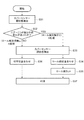
ここで、プリンターの動作について、図7を参照して説明する。図7は、プリンターの動作を示すフローチャートであり、詳しくは、カバーセンサーによりカバー開閉状態を検出したときに記録媒体としてのロール紙交換の有無を判断してロール紙を初期位置に位置決めする動作を示す。
(About printer operation)
Here, the operation of the printer will be described with reference to FIG. FIG. 7 is a flowchart showing the operation of the printer. Specifically, the operation of positioning the roll paper at the initial position by determining whether or not the roll paper as the recording medium is replaced when the cover open / close state is detected by the cover sensor. Show.
図7に示すように、ステップS31において、図5に示すセンサー制御部51は、プリンター2のカバー35が開状態になったことをカバーセンサー61の出力信号により検出する。なお、カバー35は、ロール紙22の交換や補充、その他メンテナンスの場合に開けられる。
As shown in FIG. 7, in step S <b> 31, the
次いで、ステップS32において、図3に示すプリンター2のロール紙22の収容部70に設けられたニアーエンド検出手段80の出力信号を監視する。ここでは、ニアーエンド検出手段80の出力信号にあったか否か、すなわち、ロール紙22に何らかの作業が加わったか否かを判定する。ニアーエンド検出手段80の出力信号に変化があった場合は、出力信号が紙有り状態から紙無し状態に変化し、その後紙無し状態から紙有り状態に復帰したか否かを監視する。ニアーエンド検出手段80の出力信号に変化が無い場合(NO)は、ロール紙22に何らの作業も行われていない、すなわちロール紙22の交換がなかったと判断してA処理を選択してステップS33に進む。
Next, in step S32, the output signal of the near-
ステップS33においては、プリンター2のカバー35が閉じられ、カバーセンサー61の出力信号が閉状態を示していることを確認する。その後、ステップS36に進み、ロール紙22(帳票10)の印字位置合わせを実施する。詳しくは、図5に示す搬送制御部44が搬送モーター33を動作させ、ロール紙22の紙送り動作を行いつつ、ロール紙22に設けられたブラックマークBMをBMセンサー64で検出し現状の位置を認識する。そして、さらに、正方向もしくは逆方向に紙送り動作を行いロール紙22(帳票10)の被印刷開始位置を図2及び図4に示す印刷位置PPに合わせる。そして印刷指令を受信するまで待機する。ホストコンピューター3からの印刷指令を受信すると、ステップS37に進み、印刷を実施し、帳票カット処理を実行し帳票10を順次出力する。
In step S33, it is confirmed that the
前述のステップS32において、ニアーエンド検出手段80の出力信号に変化があり(YES)、出力信号が紙有り状態から紙無し状態に変化し、その後紙無し状態から紙有り状態に復帰した場合は、使用済みのロール紙22が取り除かれ新たなロール紙22が収容された、すなわち、ロール紙22の交換があったと判断してB処理を選択してステップS33に進む。
If the output signal of the near-end detection means 80 has changed in the above-described step S32 (YES), and the output signal has changed from the paper presence state to the paper absence state, and then returns from the paper absence state to the paper presence state, It is determined that the
ステップS33においては、プリンター2のカバー35が閉じられ、カバーセンサー61の出力信号が閉状態を示していることを確認する。その後、ステップS34に進み、ロール紙22(帳票10)の位置合わせを実施する。詳しくは、紙送り動作を行いつつ、ロール紙22に設けられたブラックマークBMをBMセンサー64で検出し現状の位置を認識する。そして、ロール紙22(帳票10)の正方向もしくは逆方向に紙送り動作を行いプリンター2のカッター位置CP(図2参照)とロール紙22の被カット位置CL(図4参照)とを合わせる。そしてステップS35に進む。
In step S33, it is confirmed that the
ステップS35では、カッターユニット25のカッター駆動モーター32(図5参照)のを動作させ、ロール紙22を被カット位置CLでカットする。そして、必要があれば、正方向もしくは逆方向に紙送り動作を行いロール紙22(帳票10)の被印刷開始位置を図2及び図4に示す印刷位置PPに合わせる。そして印刷指令を受信するまで待機する。ホストコンピューター3からの印刷指令を受信すると、ステップS37に進み、印刷を実施し、帳票カット処理を実行し帳票10を順次出力する。
In step S35, the cutter drive motor 32 (see FIG. 5) of the
以下に本実施形態の効果を述べる。
(1)ブラックマークBMが設けられ、印刷開始位置やカット位置が定まっている帳票10を印刷し発行するプリンター2は、機構レイアウトや各構成要素の配置位置の関係で印刷処理やカット処理をする場合、位置合わせが必要になる。特に、ロール紙22を交換した場合は、以降の印刷発行処理を確実なものとするためロール紙22の位置合わせが重要になる。また、例えばサーマル方式のプリンター2は、カバー35側に設けられたプラテン23と本体側に設けられたサーマルヘッド24により、カバー35を閉めるとロール紙22が挟持される構成となっている。このようなプリンター2では、ロール紙22を交換する場合でなくても、カバー35を開けると挟持されていたロール紙22開放されて位置がずれてしまい、その状態でカバー35を締めるとロール紙22の位置がずれて挟持される。そのため、ロール紙22の位置合わせが必要になる。
The effects of this embodiment will be described below.
(1) The
上述のプリンター2は、カバーセンサー61及びニアーエンド検出手段80の出力信号を監視することにより、カバー35が開閉された場合、ロール紙22交換がされたか否かを判定することができる。そして、ロール紙22交換がされたか否かによってロール紙22の位置合わせの処理を最適なものに選択することができる。そのため、無駄な作業を省略することができ、作業効率の向上を図ることができる。同時にスループットの低下を抑えることができる。
The
(2)上述のプリンター2は、ロール紙22交換がされなかった場合、カット動作を省略することができる。そのため、カット動作において、ロール紙22の位置ずれに起因する小さな紙片の発生や空カットを防止することができる。その結果、紙ジャム等の不具合を防止することができる。また、空カットによるカッター寿命の低下を防止することができる。
(2) The
1…印刷システム、2…記録装置としてのプリンター、3…ホストコンピューター、4…制御部、10…帳票、22…記録媒体としてのロール紙、23…搬送手段としてのプラテン、24…記録手段としてのサーマルヘッド、25…カット手段としてのカッターユニット、32…カッター駆動モーター、33…搬送モーター、35…カバー、41…記録制御部、42…距離検出部、43…処理位置制御部、44…搬送制御部、46…記憶部、61カバー開閉検出手段としてのカバーセンサー、64…マーク検出手段としてのBMセンサー、70…収容部、80…ニアーエンド検出手段、BM…位置検出用マークとしてのブラックマーク、CL…被カット位置、CP…カッター位置。
DESCRIPTION OF SYMBOLS 1 ... Printing system, 2 ... Printer as recording apparatus, 3 ... Host computer, 4 ... Control part, 10 ... Form, 22 ... Roll paper as recording medium, 23 ... Platen as conveyance means, 24 ... As recording means
Claims (7)
前記記録媒体を収容するカバー付きの収容部と、
前記カバーの開閉状態を検出するカバー開閉検出手段と、
前記収容部に収容される前記記録媒体の残量が所定の量以下になったことを検出するニアーエンド検出手段と、
前記記録媒体の搬送経路上に設けられ、前記記録媒体上に搬送方向に沿って所定間隔で設けられている位置検出用マークを検出するマーク検出手段と、
前記搬送手段によって搬送される前記記録媒体を所定の位置に合わせる位置合わせ手段と、
前記搬送手段により前記記録媒体が搬送される搬送経路上に設けられ、前記記録媒体をカットするカット手段と、を備え、
前記カバー開閉検出手段及び前記ニアーエンド検出手段の検出状態に基づいて、前記マーク検出手段の検出結果を用いて、前記位置合わせ手段による前記記録媒体の位置合わせ、及び/または、前記カット手段による前記記録媒体のカット、を実施することを特徴とする記録装置。 A recording device that records information by a recording unit and issues it as a single sheet to a recording medium conveyed by a conveying unit,
An accommodating portion with a cover for accommodating the recording medium;
A cover open / close detecting means for detecting an open / closed state of the cover;
Near-end detection means for detecting that the remaining amount of the recording medium accommodated in the accommodating portion has become a predetermined amount or less,
Mark detection means provided on a conveyance path of the recording medium and detecting position detection marks provided at predetermined intervals along the conveyance direction on the recording medium;
Positioning means for aligning the recording medium conveyed by the conveying means with a predetermined position;
Provided on a conveyance path along which the recording medium is conveyed by the conveyance means, and a cutting means for cutting the recording medium,
Based on the detection states of the cover open / close detection means and the near end detection means, using the detection result of the mark detection means, alignment of the recording medium by the alignment means and / or recording by the cut means A recording apparatus for cutting a medium.
前記記録媒体は交換されたと判断して、前記マーク検出手段の検出結果を用いて、前記位置合わせ手段による前記記録媒体の位置合わせ、及び、前記カット手段による前記記録媒体のカット、を実施することを特徴とする請求項1乃至3のいずれか一項に記載の記録装置。 When the cover open / close detection means detects the opening / closing of the cover, and the near end detection means detects a near end state of the recording medium, and then detects a non-near end state,
It is determined that the recording medium has been replaced, and using the detection result of the mark detection means, the recording medium is aligned by the alignment means, and the recording medium is cut by the cutting means. The recording apparatus according to claim 1, wherein the recording apparatus is a recording apparatus.
前記記録媒体は交換されてないと判断して、
前記マーク検出手段の検出結果を用いて、前記位置合わせ手段による前記記録媒体の位置合わせを実施し、前記カット手段による前記記録媒体のカットを実施しないことを特徴とする請求項1乃至3のいずれか一項に記載の記録装置。 When the cover open / close detection means detects the opening / closing of the cover, but the near end detection means does not detect the near end state of the recording medium,
Determining that the recording medium has not been replaced,
4. The recording medium according to claim 1, wherein the position of the recording medium is adjusted by the positioning means using the detection result of the mark detection means, and the cutting of the recording medium is not performed by the cutting means. A recording apparatus according to claim 1.
前記記録装置は、前記記録媒体を収容するカバー付きの収容部と、前記カバーの開閉状態を検出するカバー開閉検出手段と、前記収容部に収容される前記記録媒体の残量が所定の量以下になったことを検出するニアーエンド検出手段と、前記記録媒体の搬送経路上に設けられ、前記記録媒体上に搬送方向に沿って所定間隔で設けられている位置検出用マークを検出するマーク検出手段と、前記搬送手段によって搬送される前記記録媒体を所定の位置に合わせる位置合わせ手段と、前記搬送手段により前記記録媒体が搬送される搬送経路上に設けられ、前記記録媒体をカットするカット手段と、を備え、
前記カバー開閉検出手段及び前記ニアーエンド検出手段の検出状態に基づいて、前記マーク検出手段の検出結果を用いて、前記位置合わせ手段による前記記録媒体の位置合わせ、及び/または、前記カット手段による前記記録媒体のカットを実施することを特徴とする記録装置の制御方法。 A control method for a recording apparatus that records information on a recording medium conveyed by a conveying means and issues it as a single sheet,
The recording apparatus includes: a storage unit with a cover that stores the recording medium; a cover open / close detection unit that detects an open / closed state of the cover; and a remaining amount of the recording medium stored in the storage unit is a predetermined amount or less. Near-end detection means for detecting that the recording medium has been detected, and mark detection means for detecting position detection marks provided on the recording medium at a predetermined interval along the conveyance direction. Positioning means for aligning the recording medium transported by the transporting means to a predetermined position, and cutting means provided on a transport path for transporting the recording medium by the transporting means, and cutting the recording medium With
Based on the detection states of the cover open / close detection means and the near end detection means, using the detection result of the mark detection means, alignment of the recording medium by the alignment means and / or recording by the cut means A method for controlling a recording apparatus, comprising cutting a medium.
前記カバー開閉検出手段及び前記ニアーエンド検出手段の検出状態に基づいて、前記マーク検出手段の検出結果を用いて、前記位置合わせ手段による前記記録媒体の位置合わせ、及び/または、前記カット手段による前記記録媒体のカットを実施することを特徴とする制御部が実行可能なプログラム。 Conveying means for conveying a recording medium, recording means for recording information on the recording medium, an accommodating portion with a cover for accommodating the recording medium, a cover open / close detecting means for detecting an open / closed state of the cover, and the accommodating Near-end detection means for detecting that the remaining amount of the recording medium accommodated in the recording unit has become a predetermined amount or less, provided on the recording medium conveyance path, and predetermined on the recording medium along the conveyance direction Mark detecting means for detecting position detection marks provided at intervals, positioning means for aligning the recording medium conveyed by the conveying means to a predetermined position, and the recording medium being conveyed by the conveying means A program that can be executed by a control unit that controls a recording apparatus that is provided on a conveyance path and includes a cutting unit that cuts the recording medium,
Based on the detection states of the cover open / close detection means and the near end detection means, using the detection result of the mark detection means, alignment of the recording medium by the alignment means and / or recording by the cut means A program that can be executed by a control unit that cuts a medium.
Priority Applications (2)
| Application Number | Priority Date | Filing Date | Title |
|---|---|---|---|
| JP2011133940A JP2013000968A (en) | 2011-06-16 | 2011-06-16 | Recording apparatus, control method for recording apparatus and program |
| CN 201220220478 CN202623530U (en) | 2011-06-16 | 2012-05-16 | Recording device |
Applications Claiming Priority (1)
| Application Number | Priority Date | Filing Date | Title |
|---|---|---|---|
| JP2011133940A JP2013000968A (en) | 2011-06-16 | 2011-06-16 | Recording apparatus, control method for recording apparatus and program |
Publications (2)
| Publication Number | Publication Date |
|---|---|
| JP2013000968A true JP2013000968A (en) | 2013-01-07 |
| JP2013000968A5 JP2013000968A5 (en) | 2014-07-17 |
Family
ID=47376762
Family Applications (1)
| Application Number | Title | Priority Date | Filing Date |
|---|---|---|---|
| JP2011133940A Pending JP2013000968A (en) | 2011-06-16 | 2011-06-16 | Recording apparatus, control method for recording apparatus and program |
Country Status (2)
| Country | Link |
|---|---|
| JP (1) | JP2013000968A (en) |
| CN (1) | CN202623530U (en) |
Cited By (2)
| Publication number | Priority date | Publication date | Assignee | Title |
|---|---|---|---|---|
| JP2017035858A (en) * | 2015-08-13 | 2017-02-16 | セイコーエプソン株式会社 | Printer and control method for the same |
| JP2019209627A (en) * | 2018-06-06 | 2019-12-12 | 凸版印刷株式会社 | Printer |
Families Citing this family (3)
| Publication number | Priority date | Publication date | Assignee | Title |
|---|---|---|---|---|
| CN103400455B (en) * | 2013-08-19 | 2015-06-10 | 崔贵国 | Method and device for printing lotteries |
| JP6358281B2 (en) * | 2016-03-31 | 2018-07-18 | ブラザー工業株式会社 | Printing device |
| JP6885254B2 (en) * | 2017-08-02 | 2021-06-09 | カシオ計算機株式会社 | Printing device, printing control method of printing device, and program |
Citations (3)
| Publication number | Priority date | Publication date | Assignee | Title |
|---|---|---|---|---|
| JP2002200806A (en) * | 2001-01-05 | 2002-07-16 | Seiko Epson Corp | Printer, controlling method therefor, and computer- readable information recording medium |
| JP2005319740A (en) * | 2004-05-11 | 2005-11-17 | Seiko Epson Corp | Printer |
| JP2011046128A (en) * | 2009-08-27 | 2011-03-10 | Seiko Epson Corp | Printer |
-
2011
- 2011-06-16 JP JP2011133940A patent/JP2013000968A/en active Pending
-
2012
- 2012-05-16 CN CN 201220220478 patent/CN202623530U/en not_active Expired - Fee Related
Patent Citations (3)
| Publication number | Priority date | Publication date | Assignee | Title |
|---|---|---|---|---|
| JP2002200806A (en) * | 2001-01-05 | 2002-07-16 | Seiko Epson Corp | Printer, controlling method therefor, and computer- readable information recording medium |
| JP2005319740A (en) * | 2004-05-11 | 2005-11-17 | Seiko Epson Corp | Printer |
| JP2011046128A (en) * | 2009-08-27 | 2011-03-10 | Seiko Epson Corp | Printer |
Cited By (3)
| Publication number | Priority date | Publication date | Assignee | Title |
|---|---|---|---|---|
| JP2017035858A (en) * | 2015-08-13 | 2017-02-16 | セイコーエプソン株式会社 | Printer and control method for the same |
| JP2019209627A (en) * | 2018-06-06 | 2019-12-12 | 凸版印刷株式会社 | Printer |
| JP7071879B2 (en) | 2018-06-06 | 2022-05-19 | 凸版印刷株式会社 | Printing equipment |
Also Published As
| Publication number | Publication date |
|---|---|
| CN202623530U (en) | 2012-12-26 |
Similar Documents
| Publication | Publication Date | Title |
|---|---|---|
| JP5803243B2 (en) | RECORDING DEVICE, RECORDING DEVICE CONTROL METHOD, AND PROGRAM | |
| US20060279624A1 (en) | Printer, printing control method for a printer and computer program for a printer | |
| JP6024426B2 (en) | Printing medium and printing device | |
| JP2013000968A (en) | Recording apparatus, control method for recording apparatus and program | |
| JP4396662B2 (en) | Printer, print control method, and program | |
| CN108068478B (en) | Printing apparatus and control method of printing apparatus | |
| JP2014151604A (en) | Printer | |
| JP2010513088A (en) | Double-sided thermal printing detection | |
| TWI486262B (en) | A recording device, a recording medium, and a recording device | |
| JP2006198859A (en) | Recording apparatus and method for controlling recording apparatus | |
| JP2015098149A (en) | Printer | |
| JP4746688B2 (en) | Near-end detection device and printer for rolled recording medium | |
| JP2021121496A (en) | Printer and printer control method | |
| JP2007001264A (en) | Printing device and ribbon cassette | |
| JP2017087658A (en) | Recording device and control method for the same | |
| JP2005059233A (en) | Roll shape medium printer | |
| JP2011207075A (en) | Recording device and head inspection method in the recording device | |
| JP5625828B2 (en) | Printing device | |
| JP2020158308A (en) | Printer, controlling method of printer and program | |
| TWI469879B (en) | The recording paper transfer control method and the printer of the printer | |
| US9522544B2 (en) | Thermal printer head with print control devices | |
| JP2014104606A (en) | Printer control method and printer system | |
| JP2005178093A (en) | Printer, recording paper information reading method, detection method of remaining amount of recording paper and recording paper roll | |
| US20240092088A1 (en) | Printer device | |
| JP2018158558A (en) | Printing device |
Legal Events
| Date | Code | Title | Description |
|---|---|---|---|
| A521 | Written amendment |
Free format text: JAPANESE INTERMEDIATE CODE: A523 Effective date: 20140530 |
|
| A621 | Written request for application examination |
Free format text: JAPANESE INTERMEDIATE CODE: A621 Effective date: 20140530 |
|
| RD04 | Notification of resignation of power of attorney |
Free format text: JAPANESE INTERMEDIATE CODE: A7424 Effective date: 20150107 |
|
| A977 | Report on retrieval |
Free format text: JAPANESE INTERMEDIATE CODE: A971007 Effective date: 20150205 |
|
| A131 | Notification of reasons for refusal |
Free format text: JAPANESE INTERMEDIATE CODE: A131 Effective date: 20150210 |
|
| A521 | Written amendment |
Free format text: JAPANESE INTERMEDIATE CODE: A523 Effective date: 20150410 |
|
| A02 | Decision of refusal |
Free format text: JAPANESE INTERMEDIATE CODE: A02 Effective date: 20150512 |