JP2012533892A - Tracking device for photovoltaic system and method for installing such a tracking device - Google Patents
Tracking device for photovoltaic system and method for installing such a tracking device Download PDFInfo
- Publication number
- JP2012533892A JP2012533892A JP2012520917A JP2012520917A JP2012533892A JP 2012533892 A JP2012533892 A JP 2012533892A JP 2012520917 A JP2012520917 A JP 2012520917A JP 2012520917 A JP2012520917 A JP 2012520917A JP 2012533892 A JP2012533892 A JP 2012533892A
- Authority
- JP
- Japan
- Prior art keywords
- tracking device
- support structure
- support
- tracking
- drive
- Prior art date
- Legal status (The legal status is an assumption and is not a legal conclusion. Google has not performed a legal analysis and makes no representation as to the accuracy of the status listed.)
- Pending
Links
Images


Classifications
-
- F—MECHANICAL ENGINEERING; LIGHTING; HEATING; WEAPONS; BLASTING
- F24—HEATING; RANGES; VENTILATING
- F24S—SOLAR HEAT COLLECTORS; SOLAR HEAT SYSTEMS
- F24S25/00—Arrangement of stationary mountings or supports for solar heat collector modules
- F24S25/70—Arrangement of stationary mountings or supports for solar heat collector modules with means for adjusting the final position or orientation of supporting elements in relation to each other or to a mounting surface; with means for compensating mounting tolerances
-
- F—MECHANICAL ENGINEERING; LIGHTING; HEATING; WEAPONS; BLASTING
- F24—HEATING; RANGES; VENTILATING
- F24S—SOLAR HEAT COLLECTORS; SOLAR HEAT SYSTEMS
- F24S25/00—Arrangement of stationary mountings or supports for solar heat collector modules
- F24S25/60—Fixation means, e.g. fasteners, specially adapted for supporting solar heat collector modules
- F24S25/61—Fixation means, e.g. fasteners, specially adapted for supporting solar heat collector modules for fixing to the ground or to building structures
- F24S25/617—Elements driven into the ground, e.g. anchor-piles; Foundations for supporting elements; Connectors for connecting supporting structures to the ground or to flat horizontal surfaces
-
- F—MECHANICAL ENGINEERING; LIGHTING; HEATING; WEAPONS; BLASTING
- F24—HEATING; RANGES; VENTILATING
- F24S—SOLAR HEAT COLLECTORS; SOLAR HEAT SYSTEMS
- F24S30/00—Arrangements for moving or orienting solar heat collector modules
- F24S30/40—Arrangements for moving or orienting solar heat collector modules for rotary movement
- F24S30/45—Arrangements for moving or orienting solar heat collector modules for rotary movement with two rotation axes
- F24S30/452—Vertical primary axis
-
- F—MECHANICAL ENGINEERING; LIGHTING; HEATING; WEAPONS; BLASTING
- F24—HEATING; RANGES; VENTILATING
- F24S—SOLAR HEAT COLLECTORS; SOLAR HEAT SYSTEMS
- F24S30/00—Arrangements for moving or orienting solar heat collector modules
- F24S2030/10—Special components
- F24S2030/13—Transmissions
- F24S2030/133—Transmissions in the form of flexible elements, e.g. belts, chains, ropes
-
- F—MECHANICAL ENGINEERING; LIGHTING; HEATING; WEAPONS; BLASTING
- F24—HEATING; RANGES; VENTILATING
- F24S—SOLAR HEAT COLLECTORS; SOLAR HEAT SYSTEMS
- F24S30/00—Arrangements for moving or orienting solar heat collector modules
- F24S2030/10—Special components
- F24S2030/13—Transmissions
- F24S2030/137—Transmissions for deriving one movement from another one, e.g. for deriving elevation movement from azimuth movement
-
- F—MECHANICAL ENGINEERING; LIGHTING; HEATING; WEAPONS; BLASTING
- F24—HEATING; RANGES; VENTILATING
- F24S—SOLAR HEAT COLLECTORS; SOLAR HEAT SYSTEMS
- F24S30/00—Arrangements for moving or orienting solar heat collector modules
- F24S2030/10—Special components
- F24S2030/14—Movement guiding means
-
- F—MECHANICAL ENGINEERING; LIGHTING; HEATING; WEAPONS; BLASTING
- F24—HEATING; RANGES; VENTILATING
- F24S—SOLAR HEAT COLLECTORS; SOLAR HEAT SYSTEMS
- F24S30/00—Arrangements for moving or orienting solar heat collector modules
- F24S2030/10—Special components
- F24S2030/18—Load balancing means, e.g. use of counter-weights
-
- Y—GENERAL TAGGING OF NEW TECHNOLOGICAL DEVELOPMENTS; GENERAL TAGGING OF CROSS-SECTIONAL TECHNOLOGIES SPANNING OVER SEVERAL SECTIONS OF THE IPC; TECHNICAL SUBJECTS COVERED BY FORMER USPC CROSS-REFERENCE ART COLLECTIONS [XRACs] AND DIGESTS
- Y02—TECHNOLOGIES OR APPLICATIONS FOR MITIGATION OR ADAPTATION AGAINST CLIMATE CHANGE
- Y02E—REDUCTION OF GREENHOUSE GAS [GHG] EMISSIONS, RELATED TO ENERGY GENERATION, TRANSMISSION OR DISTRIBUTION
- Y02E10/00—Energy generation through renewable energy sources
- Y02E10/40—Solar thermal energy, e.g. solar towers
- Y02E10/47—Mountings or tracking
-
- Y—GENERAL TAGGING OF NEW TECHNOLOGICAL DEVELOPMENTS; GENERAL TAGGING OF CROSS-SECTIONAL TECHNOLOGIES SPANNING OVER SEVERAL SECTIONS OF THE IPC; TECHNICAL SUBJECTS COVERED BY FORMER USPC CROSS-REFERENCE ART COLLECTIONS [XRACs] AND DIGESTS
- Y10—TECHNICAL SUBJECTS COVERED BY FORMER USPC
- Y10T—TECHNICAL SUBJECTS COVERED BY FORMER US CLASSIFICATION
- Y10T29/00—Metal working
- Y10T29/49—Method of mechanical manufacture
- Y10T29/4935—Heat exchanger or boiler making
- Y10T29/49355—Solar energy device making
Abstract
水平追尾装置が垂直追尾装置に機械的な手段によって確実に連結される太陽光発電システムのための追尾装置の設置を容易にするために,好ましくは,2つの調節機構が設けられる。アンカー要素(14)に対して,上昇要素(22)を,垂直軸(6)を中心に回転可能に動かすために1つの調節機構が使用される。第2の調節機構は,また,柱(16)の2つの部分(36A,36B)を,垂直軸(6)を中心に回転可能に動かすために使用される。 In order to facilitate the installation of a tracking device for a photovoltaic system in which the horizontal tracking device is securely connected to the vertical tracking device by mechanical means, preferably two adjustment mechanisms are provided. One adjustment mechanism is used to move the lifting element (22) relative to the anchor element (14) so as to be rotatable about a vertical axis (6). The second adjustment mechanism is also used to move the two parts (36A, 36B) of the column (16) rotatably about the vertical axis (6).
Description
本発明は,請求項1のプリアンブルの特徴を有する太陽光発電システムのための追尾装置およびそのような追尾装置を設置するための方法に関する。 The invention relates to a tracking device for a photovoltaic system having the preamble characteristics of claim 1 and a method for installing such a tracking device.
この種の追尾装置は欧州特許第1710651B1号明細書から得ることができる。 A tracking device of this kind can be obtained from EP 1710651 B1.
太陽光発電システムにおいて,達成可能なエネルギ収率は太陽光発電モジュールに対する太陽の入射角に依存する。そのため,エネルギ収率を増加させるために,システムの太陽光発電モジュールに,時期または日によって変化する太陽の位置を追尾させる装置を使用することが得策である。この場合,担持する支持構造を,地球の表面に対してほぼ垂直な軸を中心としてモジュールを回転させることにより,太陽光発電モジュールが太陽の軌道を追尾するように作製される垂直追尾が最初に言及されるべきである。加えて,2軸追尾の場合,太陽光発電モジュールが水平軸上を回転または傾斜する水平追尾が可能なため,理想的には太陽に対して直角が保証される。 In a photovoltaic system, the achievable energy yield depends on the incident angle of the sun on the photovoltaic module. Therefore, to increase the energy yield, it is a good idea to use a device in the system photovoltaic module that tracks the position of the sun, which changes with time or day. In this case, the vertical tracking, which is made so that the photovoltaic module tracks the solar trajectory, by rotating the module around the axis that is almost perpendicular to the surface of the earth, is first performed. Should be mentioned. In addition, in the case of two-axis tracking, since the photovoltaic module can perform horizontal tracking that rotates or tilts on the horizontal axis, ideally a right angle to the sun is guaranteed.
しかしながら,そのような追尾装置では,必要な作動動作を生成するために,垂直軸を中心とする追尾および水平軸を中心とする追尾の両方に別々の駆動部を必要とする。そのため,電気的な駆動モードにおいて,複数の動力伝達装置,モータおよび制御ユニットが必要であり,いずれの場合においても,おそらくは高価な制御装置もまた必要となる。そのような2軸追尾を有する太陽光発電システムの多大な費用は,これに関連している。結果として,約35%という追加のエネルギ収率は発生する追加費用によって大半が相殺されるため,追尾用の太陽光発電システムはこれまでのところ小さな市場シェアしか達成していない。 However, such tracking devices require separate drives for both tracking around the vertical axis and tracking around the horizontal axis in order to generate the required actuation action. Therefore, a plurality of power transmission devices, motors and control units are required in the electrical drive mode, and in any case, possibly expensive control devices are also required. This is associated with the tremendous cost of photovoltaic systems with such two-axis tracking. As a result, the additional energy yield of about 35% is largely offset by the additional costs incurred, so tracking solar power systems have so far achieved only a small market share.
この問題を解決するために,欧州特許第1710651B1号明細書によれば,垂直追尾と水平追尾の間に強制的な機械的連結が設けられる。この場合,湾曲したリングまたは湾曲したディスクとして示され,様々な高さレベルを有する湾曲したトラックを画定する上昇要素が設けられる。垂直追尾,すなわち垂直軸を中心とする回転運動時に,水平軸を中心とする回転が起こるように,関節式アームリンクの形態の連結装置を介して様々な高さレベルが太陽光発電モジュールに伝達される。この場合,連結装置は,動作時に上昇要素の湾曲またはガイドトラックに沿って移動する連結要素を含む。 In order to solve this problem, according to EP 1710651 B1, a forced mechanical connection is provided between vertical tracking and horizontal tracking. In this case, a raising element is provided, which is shown as a curved ring or a curved disk and which defines curved tracks with various height levels. Various height levels are transmitted to the photovoltaic module via a connecting device in the form of an articulated arm link so that during vertical tracking, ie rotation around the vertical axis, rotation around the horizontal axis occurs. Is done. In this case, the coupling device includes a coupling element that moves along the curvature of the rising element or the guide track during operation.
本発明の根底にある目的は,欧州特許第1710651B1号明細書から得ることができるような追尾装置をさらに改良することである。 The object underlying the present invention is to further improve the tracking device as can be obtained from EP 1710651 B1.
この目的は,本発明によれば,請求項1に記載の特徴を有する追尾装置によって,および請求項16に記載の特徴を有するそのような追尾装置を設置するための方法によって達成される。この追尾装置は,全般的には垂直追尾および水平追尾両方のための2軸追尾装置の形態である。この場合,水平追尾は,水平追尾のための追加の駆動部または追加の作動手段が必要とされず,および特に設けられることもなく,垂直追尾への強制的な機械的連結を介して行われる。
This object is achieved according to the invention by a tracking device having the features of claim 1 and by a method for installing such a tracking device having the features of
追尾装置は,いずれの場合においても,1つの太陽光発電モジュールと,垂直追尾装置および後者に強制的に機械的に連結される水平追尾装置を有する支持架台と,を含む。この場合,垂直追尾装置は,好ましくは支柱の形態であり,実質的に垂直軸を中心として回転可能な状態で取り付けられる支持構造を含む。動作時に,特に電動駆動部の支援で垂直追尾が行われ,その作動動作が支持構造に伝達される。水平追尾装置は,特に上昇要素を含み,それは様々な高さレベルを有する機械的なガイドトラックを画定する。動作時に,ガイドトラックによって画定される高さレベルは,支持構造の垂直軸を中心とする回転運動の場合には,水平軸を中心とする回転運動を生成するために,機械的連結装置の支援で太陽光発電モジュールに伝達される。この場合,連結装置は,好ましくはフォーク状の要素として構成され,動作時に,機械的なガイドトラックに沿って移動する連結要素を含む。機械的連結装置は,好ましくは支持構造に回転可能に固定された状態で連結されるため,垂直軸を中心とする回転運動の場合には,機械的連結装置がガイドトラックに沿って移動する。上昇要素は,好ましくはアンカー要素に回転可能に固定された状態で連結され,それを介して,支持架台が,太陽光発電システムのために設けられた設置面に底部で固定される。アンカー要素は,例えばグランドアンカーであり,別個のグランドアンカーが各支持架台に割り当てられている。あるいは,アンカー要素は,例えば(平)屋根への設置の場合に設けられる,外形支持構造とすることもできる。 In any case, the tracking device includes a photovoltaic module and a support frame having a vertical tracking device and a horizontal tracking device that is forcibly mechanically coupled to the latter. In this case, the vertical tracking device is preferably in the form of a post and includes a support structure mounted so as to be rotatable about a vertical axis. During operation, vertical tracking is performed, particularly with the help of an electric drive, and the operation is transmitted to the support structure. The horizontal tracking device includes in particular a lifting element, which defines a mechanical guide track with various height levels. In operation, the height level defined by the guide track is such that, in the case of rotational movement about the vertical axis of the support structure, the mechanical coupling device assists in generating rotational movement about the horizontal axis. Is transmitted to the photovoltaic module. In this case, the coupling device is preferably configured as a fork-like element and includes a coupling element that moves along a mechanical guide track in operation. Since the mechanical coupling device is preferably coupled to the support structure in a rotationally fixed manner, the mechanical coupling device moves along the guide track in the case of rotational movement about the vertical axis. The lifting element is preferably connected to the anchor element in a rotationally fixed manner, via which the support frame is fixed at the bottom to the installation surface provided for the photovoltaic system. The anchor element is, for example, a ground anchor, and a separate ground anchor is assigned to each support frame. Alternatively, the anchor element can be an outer shape support structure provided, for example, in the case of installation on a (flat) roof.
様々な高さレベルを有する機械的なガイドトラックとは,一般に,ガイドトラックによって,太陽光発電モジュールからの様々な垂直距離があらかじめ設定されることを意味するものと解釈され,前記垂直距離は,次いで,水平軸を中心とする,太陽光発電モジュールの別の傾斜につながる。好適な実施形態において,ガイドトラックは,平面図において,支柱の周りに円状で延在し,様々な高さレベルを画定するために上昇部と下降部とを有するように形成される。角度をなした状態のガイドトラックにおいて,後者は,したがって,起伏のある,例えば正弦曲線の形態で延在する。特に,ガイドトラックは上述の湾曲したリングで形成される。湾曲したリングとは,この場合,リングに形成され,あらかじめ設定された曲線に沿って延在するロッドを意味すると解釈される。 Mechanical guide tracks with various height levels are generally taken to mean that the guide track presets various vertical distances from the photovoltaic module, said vertical distance being It then leads to another inclination of the photovoltaic module about the horizontal axis. In a preferred embodiment, the guide track extends in a circle around the post in plan view and is formed with an ascending portion and a descending portion to define various height levels. In an angled guide track, the latter therefore extends in a undulating, eg sinusoidal form. In particular, the guide track is formed by the curved ring described above. A curved ring in this case is taken to mean a rod formed in the ring and extending along a preset curve.
上昇要素の特殊構造のため,回転角または方位角によって,ガイドトラックの異なる高さレベルがしたがって全般的に太陽光発電モジュールに伝達され,そのため,方位角によって,太陽光発電モジュールの設定水平傾斜角が強制的に設定される。 Due to the special structure of the ascending element, different height levels of the guide track are therefore generally transmitted to the photovoltaic module depending on the rotation angle or azimuth, so that the azimuth angle determines the set horizontal tilt angle of the photovoltaic module. Is forcibly set.
追尾装置の場合,支持架台は少なくとも1つの調節装置を有し,それによりアンカー要素に対する上昇要素の回転方向および/または支柱の異なる部分領域の互いに対する回転方向を調節することができると特に有利である。これらの調節装置は,組み立てを簡略化するか,そうでなければ動作時の再調節を容易にする役割を果たす。これらの調節装置の構成は,垂直追尾装置と水平追尾装置との間の強制的な機械的連結のため,支持架台の設定方向への精密な調整が必要であるという研究結果に基づいている。特に,例えば欧州特許第1710651B1号明細書による追尾装置の場合に設けられるような,互いに連結される複数の支持架台を有し,それらの垂直追尾が共通の駆動モータにより行われる太陽光発電システムの場合,駆動列内の公差および遊びのため,個々の太陽光発電モジュールが異なる方位角,すなわち垂直軸を中心とする異なる回転角をとるという問題がある。 In the case of a tracking device, it is particularly advantageous if the support cradle has at least one adjusting device, whereby the direction of rotation of the lifting element relative to the anchor element and / or the direction of rotation of the different partial areas of the strut relative to each other can be adjusted. is there. These adjustment devices serve to simplify assembly or otherwise facilitate readjustment during operation. The configuration of these adjustment devices is based on research results that require precise adjustment in the setting direction of the support cradle because of the forced mechanical connection between the vertical tracking device and the horizontal tracking device. In particular, a photovoltaic power generation system having a plurality of support frames connected to each other, such as those provided in the case of a tracking device according to EP 1710651 B1, for example, whose vertical tracking is performed by a common drive motor. In this case, due to tolerances and play in the drive train, there is a problem that individual photovoltaic modules take different azimuth angles, that is, different rotation angles around the vertical axis.
支持構造を,互いに対して回転可能に調節することができる2つの部分領域に分割すると,システムが運転を開始した後,そのような遊びおよび公差の影響が理由で異なる支持架台間の垂直方向が完全に同期しない場合に,個々の支持架台の垂直回転位置を,支持架台全体をアンカー要素に対して回転させることなく容易に設定することができるという利点につながる。 When the support structure is divided into two sub-regions that can be adjusted so as to be rotatable relative to each other, after the system starts operation, the vertical direction between the different support platforms due to such play and tolerance effects When not completely synchronized, this leads to the advantage that the vertical rotational positions of the individual support platforms can be easily set without rotating the entire support platform relative to the anchor element.
同様のことが,上昇要素を回転可能に位置決めするための調節装置に当てはまる。後者(上昇要素)により画定され,様々な高さレベルを有するガイドトラックは,ガイドトラックの最高点が正確に南の方角を示すように,方位点に対して正確に位置合わせされなければならない。欧州特許第1710651B1号明細書から公知の追尾装置の場合,上昇要素は,いずれの場合においても,アンカー要素に,例えば溶接等によってしっかりと連結され,したがって,結果としてアンカー要素がかなり精密な向きとなる。これは,特に複数の別個の支持架台を有する太陽光発電システムの場合には困難な場合がある。調節装置のために,したがって後で上昇要素を設定位置に正確に位置決めすることが容易に可能となる。 The same applies to the adjusting device for rotatably positioning the lifting element. Guide tracks, defined by the latter (rising elements) and having various height levels, must be accurately aligned with the azimuth so that the highest point of the guide track accurately points to the south. In the case of the tracking device known from EP 1 710 651 B1, the lifting element is in each case firmly connected to the anchor element, for example by welding, so that the anchor element has a fairly precise orientation. Become. This can be difficult, especially in the case of photovoltaic systems with a plurality of separate support platforms. Due to the adjusting device, it is therefore possible to easily position the lifting element precisely at the set position later.
上昇要素を回転可能に調節するための調節装置は,支持構造の2つの部分領域を互いに対して回転可能に調節するための調節装置から独立していることが好ましい。それらは組み合わせて使用され,2つの調節オプションとなることが好ましい。 The adjusting device for adjusting the lifting element in a rotatable manner is preferably independent of the adjusting device for adjusting the two partial regions of the support structure in a rotatable manner with respect to each other. They are preferably used in combination, resulting in two adjustment options.
好適な実施形態によれば,この目的のために,上昇要素は特に回転可能に固定された状態で,例えば溶接等によって固定足部に連結される。固定足部はアンカー要素に対する様々な回転位置に可逆的に固定されうる。調節オプションの簡単な構成に関しては,固定足部および/またはアンカー要素が,例えばねじなどの固定要素のための,特に円形の軌道に沿って湾曲した少なくとも1つのスロットガイドを有する。さらに,固定足部は,便宜上,アンカー要素上に平坦な状態で載るため,例えば円形の固定プレートを有する。これが簡単な組み立ておよび高い機械的安定性に貢献する。 According to a preferred embodiment, for this purpose, the lifting element is connected to the fixed foot, for example by welding, in a particularly fixed manner. The fixed foot can be reversibly fixed at various rotational positions relative to the anchor element. For a simple configuration of the adjustment options, the fixed foot and / or the anchor element have at least one slot guide that is curved along a circular track, in particular for a fixed element, for example a screw. Furthermore, for the sake of convenience, the fixed foot portion has, for example, a circular fixing plate in order to be mounted on the anchor element in a flat state. This contributes to simple assembly and high mechanical stability.
支持構造の部分領域を,互いに対して回転調節するための第2の調節装置については,部分領域が,それらの分割点において,互いに対して異なる回転位置に,互いに可逆的に固定できるようになっている。特に,支柱の2つの部分領域は,分割点において,フランジを介して互いに連結される。ここでも,少なくとも1つのフランジが,好ましくは円形の軌道に沿って湾曲した,ねじなどの固定要素のためのスロットガイドを有する。フランジは簡単な組立可能性および高い機械的安定性を確実にする。通常,垂直追尾のための駆動部は,2つの部分領域のうちの1つ,特に下部分領域に作用するようになっている。 For a second adjusting device for rotationally adjusting the partial areas of the support structure relative to one another, the partial areas can be reversibly fixed to one another at their dividing points at different rotational positions relative to one another. ing. In particular, the two partial areas of the column are connected to each other via a flange at the dividing point. Again, at least one flange has a slot guide for a fastening element, such as a screw, preferably curved along a circular track. The flange ensures easy assembly and high mechanical stability. Normally, the drive unit for vertical tracking acts on one of the two partial areas, in particular the lower partial area.
適切な発展によれば,例えばフォーク状の要素の形態の連結要素と支柱との間にばね要素が配置されるようになっている。 According to a suitable development, a spring element is arranged between the connecting element and the strut, for example in the form of a fork-like element.
好ましくは圧縮ばねの形態であってもよいばね要素のため,フォーク状の要素と,例えば湾曲したリングとして形成される上昇要素との間の押付力は減少する。ばね要素は,したがって,ばね要素なしでは高い摩擦力を生成していたであろう太陽光発電モジュールのかなりの慣性力を相殺する。特に,本発明により提供されるばね要素によって2軸追尾のエネルギ必要量をさらに大幅に削減することができるため,1つの駆動部でより多数の追尾装置を駆動することができる。 Due to the spring element, which may preferably be in the form of a compression spring, the pressing force between the fork-like element and the raising element, for example formed as a curved ring, is reduced. The spring element therefore counteracts the considerable inertial force of the photovoltaic module that would have generated a high frictional force without the spring element. In particular, the spring element provided by the present invention can further reduce the energy requirement for two-axis tracking, so that a larger number of tracking devices can be driven by a single drive unit.
ばね要素は,好ましくは,連結要素にトルクをかけるように配置され,前記トルクは太陽光発電モジュールによって生成されるトルクを相殺する。このように,トルクは,特定の状況下で多大となる可能性があり,また,太陽光発電モジュールによって生成されるが,ばね要素によって少なくとも部分的に補償されるため,湾曲したリングにかかる力を同様に低下させることができる。湾曲したリングとフォーク状の要素間の低い摩擦によって駆動エネルギの必要量は低下する。 The spring element is preferably arranged to apply torque to the connecting element, said torque canceling out the torque generated by the photovoltaic module. Thus, the torque can be significant under certain circumstances and is generated by the photovoltaic module but is at least partially compensated by the spring element so that the force on the curved ring is Can be reduced as well. The low friction between the curved ring and the fork-like element reduces the drive energy requirement.
好適な発展において,連結要素は少なくとも1つの回転自在に取り付けられるスリーブを有するようになっており,それによって連結要素が上昇要素のガイドトラック上に支持される。太陽光発電モジュールの追尾時,回転自在に取り付けられるスリーブは湾曲したリング上を転がるため,追尾にはわずかなエネルギ必要量のみを要する。 In a preferred development, the coupling element has at least one rotatably mounted sleeve, whereby the coupling element is supported on the guide track of the lifting element. When tracking a photovoltaic module, the rotatably mounted sleeve rolls on a curved ring, so tracking requires only a small amount of energy.
便宜上,連結要素は,この場合,互いの間に湾曲したリングの形態の上昇要素を把持する2つの指部を有するフォーク状の要素として構成される。湾曲したリングは,したがって,回転自在に取り付けられるスリーブ間に案内される。 For convenience, the connecting element is in this case configured as a fork-like element with two fingers that grip the rising element in the form of a curved ring between each other. The curved ring is therefore guided between sleeves that are rotatably mounted.
好適な発展において,支柱のばね要素の領域には保護用カラーが取り付けられる。その中のある程度の大きな力およびその変化のため,支柱がばね要素を支持することにより破損する危険性があり,そのため,例えば保護塗装が摩耗する。これは,例えば適切な耐摩耗性のプラスチックか,そうでなければ適切な金属からなる保護用カラーによって防止される。 In a preferred development, a protective collar is attached in the region of the post spring element. Due to a certain amount of force and its variation, there is a risk that the strut will be damaged by supporting the spring element, so that, for example, the protective coating is worn. This is prevented, for example, by a protective collar made of suitable wear-resistant plastic or otherwise suitable metal.
支持架台全体は金属からなることが好ましいが,それは屋外設置の必要性のため耐候性でなければならない。通常,亜鉛メッキ金属構造が使用される。個々の部分の,互いに対する回転運動により,望まない摩耗現象ならびに運転の困難が生じうる。後者は,特に,亜鉛メッキ工程時に生成される表面粗さにも起因する。これらの問題を軽減するために,好適な実施形態において,擦動要素,特に擦動スリーブが,支柱と,その上に支柱が回転自在に配置される固定足部との間に配置されるようになっている。擦動要素は,この場合,好ましくはゆるんだ状態で配置され,好ましくは耐摩耗性のプラスチックか,そうでなければ適切な金属からなる。通常,固定足部は,支柱を案内する,垂直方向に向いた直立または案内管を有する。この目的のために,後者は,直立管上に選択的に固定されるか,または直立管に差し込まれる。擦動スリーブとしての構成において,支柱と案内管との間の半径方向のガイドが前記擦動スリーブによって同時に画定される。擦動スリーブは,この場合,案内管の全長に沿って延在しうる。しかしながら,複数の擦動スリーブ,特に2つの擦動スリーブが,とりわけ特に案内管の2つの端部側面に設けられるようになっていることが好ましい。 The entire support frame is preferably made of metal, but it must be weatherproof due to the need for outdoor installation. Usually a galvanized metal structure is used. The rotational movement of the individual parts relative to each other can cause unwanted wear phenomena and operational difficulties. The latter is particularly due to the surface roughness produced during the galvanization process. In order to alleviate these problems, in a preferred embodiment, the rubbing element, in particular the rubbing sleeve, is arranged between the strut and a fixed foot on which the strut is rotatably arranged. It has become. The friction element is in this case preferably arranged in a loose state, preferably consisting of a wear-resistant plastic or otherwise a suitable metal. The fixed foot usually has a vertically oriented upright or guide tube that guides the column. For this purpose, the latter is selectively fixed on the upright pipe or plugged into the upright pipe. In the configuration as a friction sleeve, a radial guide between the strut and the guide tube is simultaneously defined by the friction sleeve. The friction sleeve can in this case extend along the entire length of the guide tube. However, it is preferred that a plurality of rubbing sleeves, in particular two rubbing sleeves, are provided in particular on the two end sides of the guide tube.
支柱と固定足部との間の表面圧力を低く維持するために,支柱は底部フランジを有し,それによって,それは擦動要素の少なくとも一部分上に支持される。擦動要素がスリーブの形態の場合,このスリーブは,好ましくは同様にフランジを有する。 In order to keep the surface pressure between the strut and the fixed foot low, the strut has a bottom flange so that it is supported on at least a portion of the friction element. If the friction element is in the form of a sleeve, this sleeve preferably also has a flange.
好適な発展において,嵐に対する保護手段が設けられ,それは支柱がアンカー要素から,特に,固定足部から外れることから守る。この目的のため,好ましくは固定足部と支柱との間を軸方向に動作するが,なお同時に回転運動を可能にするフォームフィットを形成する保持要素が設けられる。特に,固定足部に固定され,支柱の底部フランジにフォームフィット状態で,好ましくはそれに接することなく重なる保持用ラグが設けられる。 In a preferred development, protection against storms is provided, which protects the strut from detaching from the anchor element, in particular from the fixed foot. For this purpose, a holding element is provided which forms a foam fit which preferably moves axially between the fixed foot and the column but still allows rotational movement. In particular, a retaining lug is provided that is fixed to the fixed foot and overlaps the bottom flange of the column in a form-fit condition, preferably without touching it.
好ましくは複数の支持架台のために設けられる共通のモータの作動動作を伝達するために,好ましくは,欧州特許第1710651B1号明細書から公知の追尾装置のような,支柱と同心に配置され,それに例えば支材により回転可能に固定された状態で連結される円筒状のまたは管状の駆動要素が配置される。モータの作動動作を伝達するために設けられるのは駆動要素に巻き付くラップアラウンド手段として公知の弾性駆動手段である。そのような駆動手段は,例えば,ケーブル,ベルト,ストラップ,チェーン等である。好ましくはケーブルである駆動手段は,通常,駆動要素に何回か巻き付いている。ここで駆動手段と駆動要素間の可能な限り滑らない連結を確実にするため,特に駆動要素の側面を構築することによって,摩擦ブレーキが全体的に形成される。この目的のために,駆動手段が組み立てられた状態で収容されるガイドスロットが好ましくは駆動要素内に導入される。動作時,ケーブルは,したがって,周方向に対向するガイドスロットの縁端に張った状態であり,そのため摩擦が増加し,滑りが防止される。 In order to transmit the operating action of a common motor, preferably provided for a plurality of support platforms, it is preferably arranged concentrically with a strut, such as a tracking device known from EP 1 710 651 B1, For example, a cylindrical or tubular drive element connected in a state of being rotatably fixed by a supporting member is arranged. Provided for transmitting the operation of the motor is an elastic drive means known as a wraparound means which wraps around the drive element. Such driving means are, for example, cables, belts, straps, chains and the like. The drive means, preferably a cable, usually wraps around the drive element several times. Here, in order to ensure the least slippery connection between the drive means and the drive element, a friction brake is formed overall, in particular by constructing the sides of the drive element. For this purpose, a guide slot in which the drive means is assembled is preferably introduced into the drive element. In operation, the cable is therefore tensioned at the edges of the circumferentially opposed guide slots, thus increasing friction and preventing slippage.
好適な発展によれば,支柱の下部分領域のフランジは,駆動要素の上終端部を形成する。すなわち分割点は駆動要素の上端部に配置される。駆動要素の円筒状の構成において,このフランジは好ましくはカバーを形成するため,閉め切られた構造のユニットが形成される。土台上の支柱の支持領域はそのためより一層保護される。 According to a preferred development, the flange in the lower part region of the column forms the upper end of the drive element. That is, the dividing point is arranged at the upper end portion of the driving element. In the cylindrical configuration of the drive element, this flange preferably forms a cover, so that a unit with a closed structure is formed. The support area of the column on the foundation is thus further protected.
好ましくは,追尾装置は,複数の支持架台を含み,それらには共通の駆動部が割り当てられ,駆動部によって発揮される作動動作が,例えばケーブルなどの駆動手段を介して支柱に伝達される。この場合,支持架台は,通常,互いに並んで一列に方向付けられている。例えば,10〜30の支持架台が共通の駆動部に割り当てられる。太陽光発電システムはいくつかのそのような列からなりうる。 Preferably, the tracking device includes a plurality of support platforms, to which a common drive unit is assigned, and an operation performed by the drive unit is transmitted to the support via a drive unit such as a cable. In this case, the support platforms are usually oriented in a row alongside one another. For example, 10 to 30 support platforms are assigned to a common drive unit. A photovoltaic system can consist of several such rows.
この目的は請求項16に記載の特徴を有する方法によってさらに達成される。後者によれば,追尾装置を設置するため,調節装置の支援で,上昇要素および/または支持構造の上部領域は,定められた設定位置に移動するようになっている。特に後者の場合においては,例えばケーブルを張る等などの初期運転時の公差および遊びの自由度を考慮に入れるために,作動動作が少なくとも一旦あらかじめ駆動部から支持構造に伝達される。特に,複数の支持架台の配置において,初期運転時,前にとっていた回転位置は,通常,個々の太陽光発電モジュールが異なる垂直回転位置を向くように調節される。
This object is further achieved by a method having the features of
従属請求項は,調節装置の特定の構成と無関係に実施することもできる別個の発明の概念をある程度含む。これは,第1に,請求項5〜8に記載のばね要素の構成および配置の態様と,請求項9に記載のスリーブの態様と,請求項10および11に記載の擦動要素の配置および構成の態様と,特に,請求項12に記載のガイドスロットを有する摩擦ブレーキの態様とに関する。本出願人らは,調節装置の構成とは無関係にこれらの態様のそれぞれに関する一部出願を申請する権利を保有する。
The dependent claims contain, to some extent, separate inventive concepts which can also be implemented independently of the specific configuration of the adjusting device. Firstly, the configuration and arrangement of the spring element according to claims 5 to 8, the embodiment of the sleeve according to claim 9, the arrangement of the friction element according to
以下の文において,いずれの場合においても部分的に簡略化した図である図面に基づいて,本発明の例示的な実施形態がより詳細に説明される。 In the following text, exemplary embodiments of the invention will be described in more detail on the basis of drawings, which in each case are partially simplified.
図において,同様に動作する部分には同じ参照符号が付与される。 In the figure, parts that operate in the same manner are given the same reference numerals.
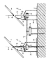
図1は,2軸追尾装置を有する,欧州特許第1710651B1号明細書による先行技術から公知の太陽光発電システムを示す。太陽光発電システムは,それぞれが太陽光発電モジュール4を支持する複数の支持架台2を有する。例示的な実施形態において,2つの支持架台2が例として示される。太陽光発電モジュール4のそれぞれは,垂直軸6を中心として,および水平回転軸8を中心として回転可能である。共同調節および追尾のために設けられるのが,垂直追尾のために,個々の支持架台2のそれら各々の軸6を中心とする同期回転を行うために,例示的な実施形態においてはケーブル12の形態である駆動手段により作動動作を各々の支持架台2に伝達する共通の駆動モータ10である。そのような垂直追尾が行われる場合に,回転軸8を中心とする水平追尾が同時に強制的な機械的連結により強制的に行われる。
FIG. 1 shows a photovoltaic system known from the prior art according to EP 1710651 B1 with a two-axis tracking device. The solar power generation system has a plurality of support frames 2 that each support the solar power generation module 4. In the exemplary embodiment, two
支持架台2は,全体的にアンカー要素14により地面に固定される。例示的な実施形態において,別々のアンカー要素14が各支持架台2に割り当てられる。前記アンカー要素14は,地面に打ち込まれるアンカー柱を有する地面板を含む。
The
支柱16が,アンカー要素14上に回転可能な状態で配置される。支柱16は垂直方向に延在し,垂直回転軸6と同心に方向付けられる。その上端部において,支柱16は,支持フレーム18(特に,図2を参照)に連結される。水平回転軸8は,支柱16またはその延長部に交差する。駆動モータ10の作動動作を伝達するために,円筒として形成され,そして,例えば連結支材を介して支柱16に連結される駆動要素20が,支柱16上に固定される。ケーブル12はこの駆動要素20の周りに案内され,後者に好ましくは何回か巻き付く。示される例示的な実施形態において,支柱16は,駆動要素20と共に,垂直追尾のための支持架台2の支持構造の要素を形成し,前記支持構造は垂直軸6を中心として回転可能な状態で取り付けられ,したがって同時に垂直追尾装置の必須要素も形成する。
A
強制的に連結される垂直追尾に,水平追尾装置が設けられる。後者は,例示的な実施形態において湾曲したリング22の形態であり,支柱16の周りに同心で形成され,様々な高さレベルを有する機械的なガイドトラック24を画定する環状要素である上昇要素を含む。湾曲したリング22はアンカー要素14に固定要素26によりしっかりと連結される。さらに,水平追尾装置は,例示的な実施形態において関節式アームリンクからなる機械的連結装置を含む。後者は実質的にその支柱端部によってそれに回転可能に固定される連結要素28からなる。その反対端において,それは同様にレバーアーム30に回転可能に連結され,次にレバーアーム30は回転可能な状態で支持フレーム18に連結される(図2を参照)。支持フレーム18上のレバーアーム30の連結点は水平回転軸8から間隔を置いて配置されるため,レバーアーム30の垂直作動動作が水平回転につながる。
A horizontal tracking device is provided for the vertical tracking that is forcibly connected. The latter is in the form of a
連結要素28は,垂直軸6を中心とする回転運動の場合にはガイドトラック24によって強制的に案内されるため,上昇要素(湾曲したリング22)によってあらかじめ設定された様々な高さレベルを有する湾曲したトラックに沿って移動する。例示的な実施形態において,連結要素28は,フォーク状の要素の形態であり,その2つのフォーク状の端部が湾曲したリング22の周りに係合する。
Since the connecting
太陽光発電システムの動作時,可能な限り効率を高めるために個々の太陽光発電モジュール4を正確に位置合わせすることが重要である。始動時または運転継続中,例えば駆動列内の遊びおよび公差の影響のため,個々の支持架台2,したがって太陽光発電モジュール4は,それらの垂直軸6を中心とする回転位置に対して,様々な回転位置をとるという問題が起こりうることが明らかとなっている。さらに,上昇要素22を所望の設定回転位置に正確に位置決めすることが困難であることが明らかとなっている。上昇要素22の最高点は南を向いていなければならない。
During operation of the photovoltaic system, it is important that the individual photovoltaic modules 4 are accurately aligned in order to increase the efficiency as much as possible. During start-up or during operation, for example due to play and tolerance effects in the drive train, the
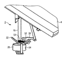
これらの問題を解決するために,以下の文で図2〜図4と共により詳細に説明されるように,2つの調節装置が設けられる。第1の調節装置は,垂直軸6に対して上昇要素22を所望の設定回転位置に調節する役割を果たす。この第1の調節装置は,例示的な実施形態においては円形の固定プレートの形態であり,それによって支持架台2全体がアンカー要素14に固定される固定足部32を実質的に含む。固定足部32は,この場合,固定具が取り外された後,固定足部32の回転位置を変えることができるように,取り外し可能な固定具,特にねじ状の固定具によってアンカー要素14に連結される。この目的のために,例示的な実施形態において,固定足部32は,円弧の形態で延在し,それを通じて固定ねじが差し込まれうる2つのスロットガイドを有する。この構成のため,したがって,支持架台2をアンカー要素14上に設置した後でも,特に各々のアンカー要素14に対する上昇要素22の回転位置を変える,および正確に設定することが可能となる。アンカー要素14の精密な位置合わせはしたがって必要ない。
In order to solve these problems, two adjustment devices are provided, as will be explained in more detail in the following text in conjunction with FIGS. The first adjustment device serves to adjust the lifting
第2の調節装置は,他の太陽光発電モジュール4との精密でない同期位置合わせの場合には,垂直軸6を中心とする各々の太陽光発電モジュール4の回転位置を調節する役割を果たす。この目的のために,支柱16は上部分領域36Aと下部分領域36Bとにさらに分割される。これらの2つの部分領域36A,36Bは,特に,それらの互いに対する相対的な回転位置を設定することができるように,分割点において可逆および取り外し可能な状態で互いに固定される。この場合,分割点は,連結装置が支柱に固定される連結点のほぼ下に配置される。さらに,分割点は,駆動列によって発揮される駆動力が支柱16に伝達される連結点の上に配置される。
The second adjusting device plays a role of adjusting the rotational position of each photovoltaic power module 4 around the vertical axis 6 in the case of inaccurate synchronous positioning with the other photovoltaic power modules 4. For this purpose, the
この目的のために,いずれの場合においても,2つの部分領域36A,36Bの端部に固定フランジ38が形成される。少なくとも1つの固定フランジ38はスロットガイド34を備えて固定足部32と類似の状態で形成される。支持架台2の上領域の回転位置は,したがって,これが駆動部10の駆動力が伝達される下部分領域36Aに影響を及ぼすことなく容易に再調節することができる。したがって,分割点を介して,非連結オプションが一般に駆動列と上部分領域との間に画定される。
For this purpose, in any case, a fixing
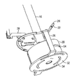
例示的な実施形態において,下部分領域36Bのフランジ38は,同時に円筒状の駆動要素20の上カバーを形成する。全般的に,その結果,特に,支柱16の支点が保護された状態で収容される,大部分が閉め切られた内部キャビティが生成される。固定フランジ38は,特に,駆動要素20から幾分間隔をおいて配置されているため,垂直追尾時に可能な限り少ない摩擦が生じる。示される例示的な実施形態とは対照的に,固定フランジ38は好ましくは駆動要素20の上に配置され,その縁端側部を被覆する。
In the exemplary embodiment, the
特に,図3による図から得ることができるように,支柱16は固定足部32上に回転可能な状態で取り付けられる。この目的のために,固定足部32は,上に管状の支柱16が取り付けられる中央支持管40を含む。運転の困難を回避するために,例示的な実施形態において,支持スリーブ42型の擦動要素が設けられる。これらはいずれの場合においても,支持管40の下および上領域に配置される。好ましくは,2つの支持スリーブ42は一種の環状フランジを有する。支柱16は,そこに,支持スリーブ42のこの環状フランジ上に,同様に環状フランジを形成するその下端部によって支持される。そのため相対的に平坦な接点が形成される。支持スリーブ42は,例えば,耐摩耗性のプラスチックまたは適切な金属からなる。
In particular, as can be taken from the view according to FIG. 3, the
さらに,支柱が,特に,固定足部32を離れて軸方向に持ち上がることから守る一方で,同時に回転可能となるように,嵐に対する保護手段43が支柱16に設けられる。この目的のために,例示的な実施形態において,軸方向に動作するフォームフィットが固定足部32と支柱16との間,特にその底部フランジに形成される。嵐に対する保護手段43は,この場合,簡単な方法で,湾曲したラグによって形成され,特にわずかな軸方向の間隙を有して,その一端が固定足部32に固定され,その別の端部がフランジ上に突出する。
Furthermore, a storm protection means 43 is provided on the
図5および図6は,フォーク状の要素としての連結要素28の形態をより詳細に示す。連結要素28は,2つのフォーク状の端部44を含む。好適な構成において,例えばプラスチックスリーブまたは金属スリーブである,回転自在に取り付けられるスリーブ46がフォーク状の端部44それぞれの上に差し込まれる。取り付けられた状態において,これらのスリーブ46はガイドトラック24上を転がる。フォーク状の要素としての形態において,湾曲したリング22はこれらのスリーブ46間に案内される。これが可能な限り低い摩擦の案内になり,そのため駆動モータ10によってかかる駆動力を低く維持することができる。ばね要素52の領域に,シューカラー53が支柱16上に配置される。
5 and 6 show in more detail the form of the connecting
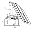
支柱16に関節式の状態で取り付けるために,連結要素28はさらに固定穴48を有する。最後に,連結要素28は,その上に,例示的な実施形態において圧縮ばねであるばね要素52が押される,延在するアーム50として形成される固定要素をさらに有する。特に,図7および図8から得ることができるように,ばね要素52は,連結要素28と支柱16との間に設置される状態で動作し,したがって,支柱16上に支持される。ばね要素52は,太陽光発電モジュール4の慣性力に対抗するように向けられた反対の力をかける。ばね要素42の配置,そのサイズおよびそのばね力/ばね定数が,したがって,この反対の力をかけるのに適した方法で選択される。その結果,上昇要素22に伝達される押付力が減少し,これが,追尾動作時に,より円滑に動く調節動作となり,モータ10にかかる負荷を全体的に開放する。ばね要素52によって生成される力が,連結要素28の固定穴48により画定される回転点を通過しないため,ばね要素52は,図5に示される図において,反時計回り方向に向けられるトルクを生成する。
In order to be attached to the
ばね要素52は連結要素28をトルクにさらすため,太陽光発電モジュール4によって生成されるトルクは全般的に相殺され,そのため湾曲したリング22にかかる負荷が低下する。湾曲したリング22に作用する力およびモーメントが低下するため,太陽光発電モジュールの追尾は,エネルギの点においてより少ない支出で行われる。同様に,ケーブル12にかかる力が低下するため,駆動モータ10は,より小さな寸法を有することができる,またはより多数の支持架台を連結することができる。
Since the
図2〜図8によれば,ガイドスロット54が駆動要素20内にさらに導入され,ケーブル12の摩擦ブレーキとしての役割を果たす。ガイドスロット54は駆動要素20の側面の部分領域上のみに延在する。ケーブル12は,ガイドスロット54を介して側面の周りに案内される。始動時のケーブルの引っ張りのため,前記ケーブルはガイドスロット54のリム側の縁端(周方向に見えるように)に配置され,そのためわずかな構造への支出のみで前記縁端が両方向に動作する摩擦ブレーキを形成する。
2 to 8, a
支持架台の記載された形態によって,そのような太陽光発電システムの費用効率の良い設置および効率運転が可能である。この,特に,2つの調節装置によって,支持架台12の,簡便で,組み立ての容易な,および設定回転位置への精密な位置合わせが問題なく可能となる。さらなる対策,特に,支持スリーブ42の配置,ばね要素52の配置およびスリーブ46の配置によって,水平調節動作に対する強制の機械的な追尾に必要な駆動力および作動力は全体的に低く維持され,そのため恒久的に信頼性の高い動作が保証される。
The described form of the support cradle allows cost-effective installation and efficient operation of such a photovoltaic system. In particular, the two adjusting devices allow the
2 支持架台
4 太陽光発電モジュール
6 垂直軸
8 水平回転軸
10 駆動モータ
12 ケーブル
14 アンカー要素
16 支柱
18 支持フレーム
20 駆動要素
22 湾曲したリング
24 ガイドトラック
26 固定要素
28 連結要素
30 レバーアーム
32 固定足部
34 スロットガイド
36A 上部分領域
36B 下部分領域
38 固定フランジ
40 支持管
42 支持スリーブ
43 嵐に対する保護手段
44 フォーク状の端部
46 スリーブ
48 固定穴
50 延在するアーム
52 ばね要素
53 保護用カラー
54 ガイドスロット
DESCRIPTION OF
Claims (16)
前記太陽光発電モジュール(4)を支持し,実質的に垂直軸(6)を中心として回転可能な状態で取り付けられる支持構造(16)を有し,駆動部(10)により垂直追尾を行う垂直追尾装置と,
水平軸(8)を中心とする回転により,前記太陽光発電モジュール(4)の水平追尾を行う水平追尾装置とを含み,前記水平追尾装置は,
様々な高さレベルを有するガイドトラック(24)を画定する上昇要素(22)であって,前記支持構造(16)は,前記上昇要素(22)に対して,前記垂直軸(6)を中心として回転可能である,上昇要素(22)と,
前記垂直軸(6)を中心として前記支持構造(16)が回転運動する場合には,連結要素(28)と共に前記ガイドトラック(24)に沿って移動し,前記水平軸(8)を中心とする回転運動を生成するために,前記ガイドトラック(24)によって画定される前記高さレベルを伝達する,機械的連結装置(28,30)と,を含み,
少なくとも1つの調節装置(32,34; 36A,36B,38)が,アンカー要素(14)に対する,前記垂直軸(6)を中心とする前記上昇要素(22)の前記回転調節のために,または,互いに対する,前記垂直軸(16)を中心とする前記支持構造(16)の部分領域(36A,36B)の前記回転調節のために,選択的にまたは組み合わせて設けられることを特徴とする,追尾装置。 A tracking device for a photovoltaic power generation system having at least one photovoltaic power generation module (4) for tracking the sun, in any case a support stand for one photovoltaic power generation module (4) (2) including the support frame (2)
A vertical structure that supports the photovoltaic power generation module (4), has a support structure (16) that is mounted so as to be substantially rotatable about a vertical axis (6), and performs vertical tracking by a drive unit (10). A tracking device;
A horizontal tracking device that performs horizontal tracking of the photovoltaic power generation module (4) by rotation about a horizontal axis (8), and the horizontal tracking device includes:
A lifting element (22) defining guide tracks (24) having various height levels, the support structure (16) being centered about the vertical axis (6) with respect to the lifting element (22) Ascending element (22), which is rotatable as
When the support structure (16) rotationally moves about the vertical axis (6), it moves along the guide track (24) together with the connecting element (28), and the horizontal axis (8) is the center. A mechanical coupling device (28, 30) that transmits the height level defined by the guide track (24) to generate a rotating motion that
At least one adjusting device (32, 34; 36A, 36B, 38) for the rotational adjustment of the lifting element (22) about the vertical axis (6) relative to the anchor element (14) or , Characterized in that they are provided selectively or in combination for the rotation adjustment of the partial regions (36A, 36B) of the support structure (16) about the vertical axis (16) relative to each other, Tracking device.
選択的にまたは組み合わせて,前記調節装置(32,34; 36A,36B,38)の支援で,必要に応じ前記個々の支持架台(2)において,
前記上昇要素(22)が前記アンカー要素(14)に対する設定回転位置に移動され,
前記支持構造(16)の第1の部分領域(36A)が,前記支持構造(16)の第2の部分領域(36B)に対する設定回転位置に移動されることを特徴とする方法。 A plurality of support platforms (2) are fixed to at least one anchor element (14), a common drive unit (10) is arranged, and the individual support structures (16) are driven by drive means (12). 16. A method for installing a tracking device according to any one of the preceding claims, wherein the tracking device is connected to a part (10) and the operating action is transmitted from the drive part (10) to the support structure (16). Because
Optionally or in combination, with the aid of the adjusting device (32, 34; 36A, 36B, 38), in the individual support cradle (2) as required,
The lifting element (22) is moved to a set rotational position relative to the anchor element (14);
Method according to claim 1, characterized in that the first partial area (36A) of the support structure (16) is moved to a set rotational position relative to the second partial area (36B) of the support structure (16).
Applications Claiming Priority (3)
| Application Number | Priority Date | Filing Date | Title |
|---|---|---|---|
| DE102009034144.7 | 2009-07-20 | ||
| DE102009034144A DE102009034144A1 (en) | 2009-07-20 | 2009-07-20 | Tracking device for a photovoltaic system |
| PCT/EP2010/003164 WO2011009508A2 (en) | 2009-07-20 | 2010-05-25 | Tracking device for a photovoltaic system, and method for installing such a tracking device |
Publications (2)
| Publication Number | Publication Date |
|---|---|
| JP2012533892A true JP2012533892A (en) | 2012-12-27 |
| JP2012533892A5 JP2012533892A5 (en) | 2013-07-11 |
Family
ID=43216411
Family Applications (1)
| Application Number | Title | Priority Date | Filing Date |
|---|---|---|---|
| JP2012520917A Pending JP2012533892A (en) | 2009-07-20 | 2010-05-25 | Tracking device for photovoltaic system and method for installing such a tracking device |
Country Status (8)
| Country | Link |
|---|---|
| US (1) | US20120152316A1 (en) |
| EP (1) | EP2457036A2 (en) |
| JP (1) | JP2012533892A (en) |
| CN (1) | CN102575879A (en) |
| AU (1) | AU2010275826A1 (en) |
| CA (1) | CA2768676A1 (en) |
| DE (1) | DE102009034144A1 (en) |
| WO (1) | WO2011009508A2 (en) |
Cited By (5)
| Publication number | Priority date | Publication date | Assignee | Title |
|---|---|---|---|---|
| JP2015126211A (en) * | 2013-12-27 | 2015-07-06 | ダイキン工業株式会社 | Photovoltaic power generation system |
| JP2015171300A (en) * | 2014-03-10 | 2015-09-28 | 大都技研株式会社 | Photovoltaic generation apparatus |
| WO2016121614A1 (en) * | 2015-01-30 | 2016-08-04 | ナブテスコ株式会社 | Panel driving device and heliostat |
| KR20200004788A (en) * | 2017-03-02 | 2020-01-14 | 어레이 테크놀로지 인코퍼레이티드 | Solar trackers incorporating spring counter-balance assemblies and spring counter-balance assemblies |
| WO2020100181A1 (en) * | 2018-11-12 | 2020-05-22 | 株式会社一 | Solar power generator |
Families Citing this family (19)
| Publication number | Priority date | Publication date | Assignee | Title |
|---|---|---|---|---|
| US7575675B2 (en) | 2006-06-19 | 2009-08-18 | Pentair Water Pool And Spa, Inc. | Pool cleaner debris bag |
| US8968559B2 (en) | 2010-05-14 | 2015-03-03 | Pentair Water Pool And Spa, Inc. | Biodegradable disposable debris bag |
| AU2010353855A1 (en) * | 2010-05-25 | 2012-12-13 | Hans-Peter Fischer | Mounting rack for a photovoltaic module and tracking device for a photovoltaic installation |
| JP5576839B2 (en) * | 2011-08-25 | 2014-08-20 | 有限会社レック | Solar tracking device |
| US9611609B2 (en) * | 2011-11-15 | 2017-04-04 | Stephen Kelleher | Ground mounting assembly |
| US10352013B2 (en) | 2011-11-15 | 2019-07-16 | Stephen Kelleher | Ground mounting assembly |
| WO2013074667A2 (en) | 2011-11-15 | 2013-05-23 | Stephen Kelleher | Solar system mounting assembly |
| ITMO20120088A1 (en) * | 2012-04-02 | 2013-10-03 | H M Solar S R L Unipersonale | SUPPORT STRUCTURE FOR SOLAR PANELS |
| ITBA20120032A1 (en) * | 2012-05-24 | 2013-11-25 | Giuseppe Giacomino | VERTICAL STRUCTURE FOR SOLAR PANELS |
| US20140251315A1 (en) * | 2013-03-06 | 2014-09-11 | Rajeev Pandit | Method and apparatus for orienting arrays of mechanically linked heliostats for focusing the incident sunlight on a stationary object |
| WO2016115391A1 (en) | 2015-01-14 | 2016-07-21 | Pentair Water Pool And Spa. Inc. | Debris bag with detachable collar |
| EP3300248B8 (en) * | 2015-05-19 | 2020-07-15 | Fuji Seiko Co., Ltd. | Solar panel rack |
| ITUB20152630A1 (en) * | 2015-07-31 | 2017-01-31 | Sandro Lucchetta | BIASSIAL SOLAR TRACK WITH MECHANICAL ADJUSTMENT FOR SOLAR ENERGY CONVERSION DEVICES |
| ES2599966B2 (en) * | 2015-08-04 | 2017-06-02 | Juan Francisco VALLS GUIRADO | Azimuth-elevation solar tracking system |
| CN105042893B (en) * | 2015-08-11 | 2017-01-25 | 中国华能集团清洁能源技术研究院有限公司 | Inclined-axis linear tracking solar concentrating and heat collection device and method |
| WO2017162565A1 (en) * | 2016-03-23 | 2017-09-28 | Raipro Gmbh | Pivotal holding, supporting, and/or adjusting device for solar modules |
| IL253535B (en) * | 2017-07-18 | 2021-07-29 | Slatics Ltd | Anchoring structure for ground mounting of solar photovoltaic system |
| DE202017105133U1 (en) * | 2017-08-25 | 2017-10-18 | Christian Rainer | Pivoting holding, supporting and / or adjusting device for solar modules |
| CN109611808B (en) * | 2018-12-14 | 2020-11-24 | 佛山科学技术学院 | Convex-concave mirror light-gathering type water tank power generation device |
Citations (4)
| Publication number | Priority date | Publication date | Assignee | Title |
|---|---|---|---|---|
| JPH10341543A (en) * | 1997-06-06 | 1998-12-22 | Kandenko Co Ltd | Communication cable wiring box device |
| JP2004047120A (en) * | 2002-05-17 | 2004-02-12 | Sankyo Alum Ind Co Ltd | Pole unit |
| JP2005039148A (en) * | 2003-07-18 | 2005-02-10 | Shinichiro Kashiwazaki | Sun tracking apparatus for solar generator |
| EP1710651A1 (en) * | 2005-03-30 | 2006-10-11 | Gümpelein, Manuela | Tracking device for a photovoltaic system |
Family Cites Families (11)
| Publication number | Priority date | Publication date | Assignee | Title |
|---|---|---|---|---|
| US4281515A (en) * | 1978-11-14 | 1981-08-04 | Energy Wise, Inc. | Solar powered cooling device |
| FR2557961B1 (en) * | 1984-01-11 | 1986-04-11 | Dupuy Pierre | ORIENTATION DEVICE FOR SOLAR COLLECTOR |
| DE4240541A1 (en) * | 1991-12-03 | 1993-07-29 | Alexander Berger | |
| DE19525994A1 (en) * | 1995-07-17 | 1997-01-23 | Fischer Reinhold | Rotary mount for solar energy collector with extended surface area used in e.g. swimming pool |
| DE20318080U1 (en) * | 2003-11-22 | 2005-04-14 | Restemeyer, Dieter | Solar energy heat recovery device comprises solar module with housing part swivel supported on driven support device and with reflective back wall and sunlight-permeable cover disc with collector tubes in interspace |
| DE102005012054B4 (en) * | 2005-03-16 | 2010-05-20 | Oskar Fleck | Bracket for solar modules on the roof |
| DE102005042478A1 (en) * | 2005-08-30 | 2007-03-01 | Karl Neff | Tracking system for a solar energy collection unit has controlled drives to adjust position by turning and tilting |
| DE202006014047U1 (en) * | 2006-09-13 | 2006-12-07 | Leichtmetallbau Schletter Gmbh | Positioning system for upright solar systems has clamping plates attached to support with grooved surfaces opposing those of inclined bar with grooves crossing |
| ES1065444Y (en) * | 2007-05-24 | 2007-11-16 | Meseguer Teodoro Domingo Cano | SOLAR PHOTOVOLTAIC INSTALLATION |
| CN201113838Y (en) * | 2007-10-22 | 2008-09-10 | 商勇杰 | Solar energy condensing photovoltaic generating plant mechanical installation |
| SE533498C2 (en) * | 2008-10-22 | 2010-10-12 | Absolicon Solar Concentrator Ab | Installation of receiver in solar collector trough |
-
2009
- 2009-07-20 DE DE102009034144A patent/DE102009034144A1/en not_active Ceased
-
2010
- 2010-05-25 CA CA2768676A patent/CA2768676A1/en not_active Abandoned
- 2010-05-25 AU AU2010275826A patent/AU2010275826A1/en not_active Abandoned
- 2010-05-25 JP JP2012520917A patent/JP2012533892A/en active Pending
- 2010-05-25 CN CN2010800323385A patent/CN102575879A/en active Pending
- 2010-05-25 EP EP10724285A patent/EP2457036A2/en not_active Withdrawn
- 2010-05-25 WO PCT/EP2010/003164 patent/WO2011009508A2/en active Application Filing
-
2012
- 2012-01-20 US US13/354,860 patent/US20120152316A1/en not_active Abandoned
Patent Citations (4)
| Publication number | Priority date | Publication date | Assignee | Title |
|---|---|---|---|---|
| JPH10341543A (en) * | 1997-06-06 | 1998-12-22 | Kandenko Co Ltd | Communication cable wiring box device |
| JP2004047120A (en) * | 2002-05-17 | 2004-02-12 | Sankyo Alum Ind Co Ltd | Pole unit |
| JP2005039148A (en) * | 2003-07-18 | 2005-02-10 | Shinichiro Kashiwazaki | Sun tracking apparatus for solar generator |
| EP1710651A1 (en) * | 2005-03-30 | 2006-10-11 | Gümpelein, Manuela | Tracking device for a photovoltaic system |
Cited By (11)
| Publication number | Priority date | Publication date | Assignee | Title |
|---|---|---|---|---|
| JP2015126211A (en) * | 2013-12-27 | 2015-07-06 | ダイキン工業株式会社 | Photovoltaic power generation system |
| JP2015171300A (en) * | 2014-03-10 | 2015-09-28 | 大都技研株式会社 | Photovoltaic generation apparatus |
| WO2016121614A1 (en) * | 2015-01-30 | 2016-08-04 | ナブテスコ株式会社 | Panel driving device and heliostat |
| KR20200004788A (en) * | 2017-03-02 | 2020-01-14 | 어레이 테크놀로지 인코퍼레이티드 | Solar trackers incorporating spring counter-balance assemblies and spring counter-balance assemblies |
| JP2020512794A (en) * | 2017-03-02 | 2020-04-23 | アレイ・テクノロジーズ・インコーポレイテッドArray Technologies, Inc. | A spring balancing assembly and a photovoltaic device incorporating the spring balancing assembly. |
| KR102451267B1 (en) * | 2017-03-02 | 2022-10-05 | 어레이 테크놀로지 인코퍼레이티드 | Spring counter-balance assemblies and solar trackers incorporating spring counter-balance assemblies |
| US11533017B2 (en) | 2017-03-02 | 2022-12-20 | Array Technologies, Inc. | Spring counter-balance assemblies and solar trackers incorporating spring counter-balance assemblies |
| JP7206209B2 (en) | 2017-03-02 | 2023-01-17 | アレイ・テクノロジーズ・インコーポレイテッド | solar tracker assembly |
| US11799416B2 (en) | 2017-03-02 | 2023-10-24 | Array Technologies, Inc. | Spring counter-balance assemblies and solar trackers incorporating springs to balance rotation |
| WO2020100181A1 (en) * | 2018-11-12 | 2020-05-22 | 株式会社一 | Solar power generator |
| JPWO2020100181A1 (en) * | 2018-11-12 | 2021-09-30 | 株式会社一 | Solar power generator |
Also Published As
| Publication number | Publication date |
|---|---|
| DE102009034144A1 (en) | 2011-06-22 |
| WO2011009508A2 (en) | 2011-01-27 |
| EP2457036A2 (en) | 2012-05-30 |
| US20120152316A1 (en) | 2012-06-21 |
| WO2011009508A3 (en) | 2011-06-30 |
| AU2010275826A1 (en) | 2012-02-09 |
| CN102575879A (en) | 2012-07-11 |
| CA2768676A1 (en) | 2011-01-27 |
Similar Documents
| Publication | Publication Date | Title |
|---|---|---|
| JP2012533892A (en) | Tracking device for photovoltaic system and method for installing such a tracking device | |
| EP2345811B1 (en) | Clamp for clamping a blade for a wind turbine and method of installing wind turbine blades | |
| KR20130076829A (en) | Mounting rack for a photovoltaic module and tracking device for a photovoltaic installation | |
| KR101713424B1 (en) | Automatic solar tracking adjustment/control apparatus of solar generation system | |
| KR100908442B1 (en) | Apparatus for adjusting inclination an of sunlight electric power apparatus | |
| US20140054433A1 (en) | Alignment and/or tracking device for solar collectors | |
| EP3449192B1 (en) | Solar tracker | |
| WO2007109901A1 (en) | Support structure kor a solar collector system | |
| CN102419013B (en) | Linkage small-sized heliostat system | |
| CN101755342A (en) | Rolling motion tracking solar assembly | |
| US20100192942A1 (en) | Solar tracking system | |
| KR101634301B1 (en) | a motorized angle control apparatus of the solar power system | |
| KR100902882B1 (en) | Solar power generating device with solar tracking system | |
| US8242424B2 (en) | Single axis solar tracker | |
| US20130075545A1 (en) | Supporting framework for a photovoltaic module and tracking device for a photovoltaic system | |
| KR200382126Y1 (en) | The sunlight tracking apparatus for solar cell unit | |
| KR200452426Y1 (en) | Solar panel angle control system | |
| EP2385327A1 (en) | One-way solar tracker | |
| KR100946731B1 (en) | Photopile power generation system by solar tracking | |
| JP5634369B2 (en) | Solar tracking solar power generation system | |
| CN102792103A (en) | Solar energy collection apparatus | |
| EA037100B1 (en) | Solar panel tracking system | |
| KR101660277B1 (en) | A solar power plant equipped with a rotating solar tracker | |
| KR20100066065A (en) | Sun location tracking type solar generation apparatus | |
| KR101661712B1 (en) | a solar tacker of solar energy device |
Legal Events
| Date | Code | Title | Description |
|---|---|---|---|
| A521 | Written amendment |
Free format text: JAPANESE INTERMEDIATE CODE: A523 Effective date: 20130527 |
|
| A621 | Written request for application examination |
Free format text: JAPANESE INTERMEDIATE CODE: A621 Effective date: 20130527 |
|
| A977 | Report on retrieval |
Free format text: JAPANESE INTERMEDIATE CODE: A971007 Effective date: 20131218 |
|
| A131 | Notification of reasons for refusal |
Free format text: JAPANESE INTERMEDIATE CODE: A131 Effective date: 20140114 |
|
| A02 | Decision of refusal |
Free format text: JAPANESE INTERMEDIATE CODE: A02 Effective date: 20140610 |