JP2012533025A - System for gas treatment - Google Patents
System for gas treatment Download PDFInfo
- Publication number
- JP2012533025A JP2012533025A JP2012519990A JP2012519990A JP2012533025A JP 2012533025 A JP2012533025 A JP 2012533025A JP 2012519990 A JP2012519990 A JP 2012519990A JP 2012519990 A JP2012519990 A JP 2012519990A JP 2012533025 A JP2012533025 A JP 2012533025A
- Authority
- JP
- Japan
- Prior art keywords
- flue gas
- compressor
- pressure
- power plant
- low
- Prior art date
- Legal status (The legal status is an assumption and is not a legal conclusion. Google has not performed a legal analysis and makes no representation as to the accuracy of the status listed.)
- Withdrawn
Links
Images
Classifications
-
- F—MECHANICAL ENGINEERING; LIGHTING; HEATING; WEAPONS; BLASTING
- F25—REFRIGERATION OR COOLING; COMBINED HEATING AND REFRIGERATION SYSTEMS; HEAT PUMP SYSTEMS; MANUFACTURE OR STORAGE OF ICE; LIQUEFACTION SOLIDIFICATION OF GASES
- F25J—LIQUEFACTION, SOLIDIFICATION OR SEPARATION OF GASES OR GASEOUS OR LIQUEFIED GASEOUS MIXTURES BY PRESSURE AND COLD TREATMENT OR BY BRINGING THEM INTO THE SUPERCRITICAL STATE
- F25J3/00—Processes or apparatus for separating the constituents of gaseous or liquefied gaseous mixtures involving the use of liquefaction or solidification
- F25J3/02—Processes or apparatus for separating the constituents of gaseous or liquefied gaseous mixtures involving the use of liquefaction or solidification by rectification, i.e. by continuous interchange of heat and material between a vapour stream and a liquid stream
- F25J3/0228—Processes or apparatus for separating the constituents of gaseous or liquefied gaseous mixtures involving the use of liquefaction or solidification by rectification, i.e. by continuous interchange of heat and material between a vapour stream and a liquid stream characterised by the separated product stream
- F25J3/0266—Processes or apparatus for separating the constituents of gaseous or liquefied gaseous mixtures involving the use of liquefaction or solidification by rectification, i.e. by continuous interchange of heat and material between a vapour stream and a liquid stream characterised by the separated product stream separation of carbon dioxide
-
- B—PERFORMING OPERATIONS; TRANSPORTING
- B01—PHYSICAL OR CHEMICAL PROCESSES OR APPARATUS IN GENERAL
- B01D—SEPARATION
- B01D53/00—Separation of gases or vapours; Recovering vapours of volatile solvents from gases; Chemical or biological purification of waste gases, e.g. engine exhaust gases, smoke, fumes, flue gases, aerosols
- B01D53/002—Separation of gases or vapours; Recovering vapours of volatile solvents from gases; Chemical or biological purification of waste gases, e.g. engine exhaust gases, smoke, fumes, flue gases, aerosols by condensation
-
- F—MECHANICAL ENGINEERING; LIGHTING; HEATING; WEAPONS; BLASTING
- F25—REFRIGERATION OR COOLING; COMBINED HEATING AND REFRIGERATION SYSTEMS; HEAT PUMP SYSTEMS; MANUFACTURE OR STORAGE OF ICE; LIQUEFACTION SOLIDIFICATION OF GASES
- F25J—LIQUEFACTION, SOLIDIFICATION OR SEPARATION OF GASES OR GASEOUS OR LIQUEFIED GASEOUS MIXTURES BY PRESSURE AND COLD TREATMENT OR BY BRINGING THEM INTO THE SUPERCRITICAL STATE
- F25J3/00—Processes or apparatus for separating the constituents of gaseous or liquefied gaseous mixtures involving the use of liquefaction or solidification
- F25J3/06—Processes or apparatus for separating the constituents of gaseous or liquefied gaseous mixtures involving the use of liquefaction or solidification by partial condensation
- F25J3/063—Processes or apparatus for separating the constituents of gaseous or liquefied gaseous mixtures involving the use of liquefaction or solidification by partial condensation characterised by the separated product stream
- F25J3/067—Processes or apparatus for separating the constituents of gaseous or liquefied gaseous mixtures involving the use of liquefaction or solidification by partial condensation characterised by the separated product stream separation of carbon dioxide
-
- B—PERFORMING OPERATIONS; TRANSPORTING
- B01—PHYSICAL OR CHEMICAL PROCESSES OR APPARATUS IN GENERAL
- B01D—SEPARATION
- B01D2256/00—Main component in the product gas stream after treatment
- B01D2256/22—Carbon dioxide
-
- B—PERFORMING OPERATIONS; TRANSPORTING
- B01—PHYSICAL OR CHEMICAL PROCESSES OR APPARATUS IN GENERAL
- B01D—SEPARATION
- B01D2257/00—Components to be removed
- B01D2257/30—Sulfur compounds
- B01D2257/302—Sulfur oxides
-
- B—PERFORMING OPERATIONS; TRANSPORTING
- B01—PHYSICAL OR CHEMICAL PROCESSES OR APPARATUS IN GENERAL
- B01D—SEPARATION
- B01D2257/00—Components to be removed
- B01D2257/40—Nitrogen compounds
- B01D2257/404—Nitrogen oxides other than dinitrogen oxide
-
- F—MECHANICAL ENGINEERING; LIGHTING; HEATING; WEAPONS; BLASTING
- F25—REFRIGERATION OR COOLING; COMBINED HEATING AND REFRIGERATION SYSTEMS; HEAT PUMP SYSTEMS; MANUFACTURE OR STORAGE OF ICE; LIQUEFACTION SOLIDIFICATION OF GASES
- F25J—LIQUEFACTION, SOLIDIFICATION OR SEPARATION OF GASES OR GASEOUS OR LIQUEFIED GASEOUS MIXTURES BY PRESSURE AND COLD TREATMENT OR BY BRINGING THEM INTO THE SUPERCRITICAL STATE
- F25J2210/00—Processes characterised by the type or other details of the feed stream
- F25J2210/70—Flue or combustion exhaust gas
-
- F—MECHANICAL ENGINEERING; LIGHTING; HEATING; WEAPONS; BLASTING
- F25—REFRIGERATION OR COOLING; COMBINED HEATING AND REFRIGERATION SYSTEMS; HEAT PUMP SYSTEMS; MANUFACTURE OR STORAGE OF ICE; LIQUEFACTION SOLIDIFICATION OF GASES
- F25J—LIQUEFACTION, SOLIDIFICATION OR SEPARATION OF GASES OR GASEOUS OR LIQUEFIED GASEOUS MIXTURES BY PRESSURE AND COLD TREATMENT OR BY BRINGING THEM INTO THE SUPERCRITICAL STATE
- F25J2220/00—Processes or apparatus involving steps for the removal of impurities
- F25J2220/80—Separating impurities from carbon dioxide, e.g. H2O or water-soluble contaminants
- F25J2220/82—Separating low boiling, i.e. more volatile components, e.g. He, H2, CO, Air gases, CH4
-
- F—MECHANICAL ENGINEERING; LIGHTING; HEATING; WEAPONS; BLASTING
- F25—REFRIGERATION OR COOLING; COMBINED HEATING AND REFRIGERATION SYSTEMS; HEAT PUMP SYSTEMS; MANUFACTURE OR STORAGE OF ICE; LIQUEFACTION SOLIDIFICATION OF GASES
- F25J—LIQUEFACTION, SOLIDIFICATION OR SEPARATION OF GASES OR GASEOUS OR LIQUEFIED GASEOUS MIXTURES BY PRESSURE AND COLD TREATMENT OR BY BRINGING THEM INTO THE SUPERCRITICAL STATE
- F25J2230/00—Processes or apparatus involving steps for increasing the pressure of gaseous process streams
- F25J2230/06—Adiabatic compressor, i.e. without interstage cooling
-
- F—MECHANICAL ENGINEERING; LIGHTING; HEATING; WEAPONS; BLASTING
- F25—REFRIGERATION OR COOLING; COMBINED HEATING AND REFRIGERATION SYSTEMS; HEAT PUMP SYSTEMS; MANUFACTURE OR STORAGE OF ICE; LIQUEFACTION SOLIDIFICATION OF GASES
- F25J—LIQUEFACTION, SOLIDIFICATION OR SEPARATION OF GASES OR GASEOUS OR LIQUEFIED GASEOUS MIXTURES BY PRESSURE AND COLD TREATMENT OR BY BRINGING THEM INTO THE SUPERCRITICAL STATE
- F25J2230/00—Processes or apparatus involving steps for increasing the pressure of gaseous process streams
- F25J2230/20—Integrated compressor and process expander; Gear box arrangement; Multiple compressors on a common shaft
-
- F—MECHANICAL ENGINEERING; LIGHTING; HEATING; WEAPONS; BLASTING
- F25—REFRIGERATION OR COOLING; COMBINED HEATING AND REFRIGERATION SYSTEMS; HEAT PUMP SYSTEMS; MANUFACTURE OR STORAGE OF ICE; LIQUEFACTION SOLIDIFICATION OF GASES
- F25J—LIQUEFACTION, SOLIDIFICATION OR SEPARATION OF GASES OR GASEOUS OR LIQUEFIED GASEOUS MIXTURES BY PRESSURE AND COLD TREATMENT OR BY BRINGING THEM INTO THE SUPERCRITICAL STATE
- F25J2230/00—Processes or apparatus involving steps for increasing the pressure of gaseous process streams
- F25J2230/30—Compression of the feed stream
-
- F—MECHANICAL ENGINEERING; LIGHTING; HEATING; WEAPONS; BLASTING
- F25—REFRIGERATION OR COOLING; COMBINED HEATING AND REFRIGERATION SYSTEMS; HEAT PUMP SYSTEMS; MANUFACTURE OR STORAGE OF ICE; LIQUEFACTION SOLIDIFICATION OF GASES
- F25J—LIQUEFACTION, SOLIDIFICATION OR SEPARATION OF GASES OR GASEOUS OR LIQUEFIED GASEOUS MIXTURES BY PRESSURE AND COLD TREATMENT OR BY BRINGING THEM INTO THE SUPERCRITICAL STATE
- F25J2230/00—Processes or apparatus involving steps for increasing the pressure of gaseous process streams
- F25J2230/32—Compression of the product stream
-
- F—MECHANICAL ENGINEERING; LIGHTING; HEATING; WEAPONS; BLASTING
- F25—REFRIGERATION OR COOLING; COMBINED HEATING AND REFRIGERATION SYSTEMS; HEAT PUMP SYSTEMS; MANUFACTURE OR STORAGE OF ICE; LIQUEFACTION SOLIDIFICATION OF GASES
- F25J—LIQUEFACTION, SOLIDIFICATION OR SEPARATION OF GASES OR GASEOUS OR LIQUEFIED GASEOUS MIXTURES BY PRESSURE AND COLD TREATMENT OR BY BRINGING THEM INTO THE SUPERCRITICAL STATE
- F25J2230/00—Processes or apparatus involving steps for increasing the pressure of gaseous process streams
- F25J2230/80—Processes or apparatus involving steps for increasing the pressure of gaseous process streams the fluid being carbon dioxide
-
- F—MECHANICAL ENGINEERING; LIGHTING; HEATING; WEAPONS; BLASTING
- F25—REFRIGERATION OR COOLING; COMBINED HEATING AND REFRIGERATION SYSTEMS; HEAT PUMP SYSTEMS; MANUFACTURE OR STORAGE OF ICE; LIQUEFACTION SOLIDIFICATION OF GASES
- F25J—LIQUEFACTION, SOLIDIFICATION OR SEPARATION OF GASES OR GASEOUS OR LIQUEFIED GASEOUS MIXTURES BY PRESSURE AND COLD TREATMENT OR BY BRINGING THEM INTO THE SUPERCRITICAL STATE
- F25J2240/00—Processes or apparatus involving steps for expanding of process streams
- F25J2240/70—Steam turbine, e.g. used in a Rankine cycle
-
- F—MECHANICAL ENGINEERING; LIGHTING; HEATING; WEAPONS; BLASTING
- F25—REFRIGERATION OR COOLING; COMBINED HEATING AND REFRIGERATION SYSTEMS; HEAT PUMP SYSTEMS; MANUFACTURE OR STORAGE OF ICE; LIQUEFACTION SOLIDIFICATION OF GASES
- F25J—LIQUEFACTION, SOLIDIFICATION OR SEPARATION OF GASES OR GASEOUS OR LIQUEFIED GASEOUS MIXTURES BY PRESSURE AND COLD TREATMENT OR BY BRINGING THEM INTO THE SUPERCRITICAL STATE
- F25J2240/00—Processes or apparatus involving steps for expanding of process streams
- F25J2240/90—Hot gas waste turbine of an indirect heated gas for power generation
-
- F—MECHANICAL ENGINEERING; LIGHTING; HEATING; WEAPONS; BLASTING
- F25—REFRIGERATION OR COOLING; COMBINED HEATING AND REFRIGERATION SYSTEMS; HEAT PUMP SYSTEMS; MANUFACTURE OR STORAGE OF ICE; LIQUEFACTION SOLIDIFICATION OF GASES
- F25J—LIQUEFACTION, SOLIDIFICATION OR SEPARATION OF GASES OR GASEOUS OR LIQUEFIED GASEOUS MIXTURES BY PRESSURE AND COLD TREATMENT OR BY BRINGING THEM INTO THE SUPERCRITICAL STATE
- F25J2260/00—Coupling of processes or apparatus to other units; Integrated schemes
- F25J2260/02—Integration in an installation for exchanging heat, e.g. for waste heat recovery
-
- Y—GENERAL TAGGING OF NEW TECHNOLOGICAL DEVELOPMENTS; GENERAL TAGGING OF CROSS-SECTIONAL TECHNOLOGIES SPANNING OVER SEVERAL SECTIONS OF THE IPC; TECHNICAL SUBJECTS COVERED BY FORMER USPC CROSS-REFERENCE ART COLLECTIONS [XRACs] AND DIGESTS
- Y02—TECHNOLOGIES OR APPLICATIONS FOR MITIGATION OR ADAPTATION AGAINST CLIMATE CHANGE
- Y02C—CAPTURE, STORAGE, SEQUESTRATION OR DISPOSAL OF GREENHOUSE GASES [GHG]
- Y02C20/00—Capture or disposal of greenhouse gases
- Y02C20/40—Capture or disposal of greenhouse gases of CO2
-
- Y—GENERAL TAGGING OF NEW TECHNOLOGICAL DEVELOPMENTS; GENERAL TAGGING OF CROSS-SECTIONAL TECHNOLOGIES SPANNING OVER SEVERAL SECTIONS OF THE IPC; TECHNICAL SUBJECTS COVERED BY FORMER USPC CROSS-REFERENCE ART COLLECTIONS [XRACs] AND DIGESTS
- Y02—TECHNOLOGIES OR APPLICATIONS FOR MITIGATION OR ADAPTATION AGAINST CLIMATE CHANGE
- Y02E—REDUCTION OF GREENHOUSE GAS [GHG] EMISSIONS, RELATED TO ENERGY GENERATION, TRANSMISSION OR DISTRIBUTION
- Y02E20/00—Combustion technologies with mitigation potential
- Y02E20/16—Combined cycle power plant [CCPP], or combined cycle gas turbine [CCGT]
Abstract
本発明によれば、化石燃料の燃焼により生じる煙道ガスを処理するためのシステム(1)を備える電気エネルギーを発生させるための発電プラントは、煙道ガスの第1の低圧圧縮のための断熱圧縮機(5)と、第2の多段式低圧煙道ガス圧縮システム(14)と、多段式高圧CO2圧縮システム(15)とを備える。低圧煙道ガス圧縮システムと高圧CO2圧縮システムとの両方は、単一の装置(C2)内で結合されており、1つの共通駆動装置(17)により駆動される1つの共通シャフト(16)上に配置されている。熱交換器(8)は、断熱圧縮された煙道ガスの冷却の結果得られる熱の回収の向上を容易にする。本発明によれば、本処理システムと統合された発電プラントの全体の動力効率を向上することができるとともに、投資コストを削減することができる。According to the present invention, a power plant for generating electrical energy comprising a system (1) for treating flue gas resulting from the combustion of fossil fuels is insulated for the first low-pressure compression of flue gas. A compressor (5), a second multi-stage low-pressure flue gas compression system (14), and a multi-stage high-pressure CO 2 compression system (15) are provided. Both the low pressure flue gas compression system and the high pressure CO 2 compression system are combined in a single device (C2) and are driven by one common drive (17) and one common shaft (16). Is placed on top. The heat exchanger (8) facilitates improved recovery of heat resulting from cooling of the adiabatically compressed flue gas. According to the present invention, it is possible to improve the overall power efficiency of the power plant integrated with the present processing system, and to reduce the investment cost.
Description
本発明は、電気エネルギーを発生させるための化石燃料火力発電プラントより生じるガスを処理するためのシステムに関する。本発明は、特に、二酸化炭素の輸送及び貯蔵を容易にするためにこのようなガスを精製するガス処理のためのシステムに関する。 The present invention relates to a system for treating gas generated from a fossil fuel-fired power plant for generating electrical energy. The invention particularly relates to a system for gas processing that purifies such gases to facilitate the transport and storage of carbon dioxide.
温室効果ガスである二酸化炭素(CO2)の大気への排出を削減する観点から、電気エネルギーを発生させるための化石燃料火力発電プラントの煙道ガスには、典型的には、いわゆるCO2捕捉システムが備えられている。煙道ガスに含まれるCO2ガスは、先ず分離され、その後に圧縮、乾燥及び冷却されることにより、永久貯蔵のために、又は石油増進回収等の更なる利用のために調整される。安全な輸送、貯蔵又は更なる利用のためには、このCO2はある程度の品質を有する必要がある。例えば、石油増進回収用には、このガスは、CO2濃度が少なくとも95%、温度が50℃未満、圧力が13.8Mpaである必要がある。化石燃料火力発電プラントからの煙道ガスには、CO2だけでなく、水蒸気、酸素、窒素、アルゴン、並びにSO3、SO2、NO及びNO2といった、多くの更なる汚染物質が含まれている。SO3、SO2、NO及びNO2は、環境規制や、CO2の輸送・貯蔵のための要件を満たすために除去する必要がある。化石燃料の種類、燃焼パラメーター及び燃焼器の設計に応じて、これら全ての汚染物質やCO2それ自体は、様々な濃度で存在する。煙道ガスに含まれるCO2の比率は、ガスタービン用ガスの燃焼の場合における4%から、燃焼プロセスに酸素を更に供給する空気分離ユニットを備える石炭焚きボイラーの場合における60%〜90%に及ぶ。煙道ガスからの汚染物質の除去は、技術的な障害によって制限されるのではなく、むしろ、追加されるコストとエネルギーに対する要求及びその結果生じる発電プラント全体での効率の低下により制限される。 From the viewpoint of reducing the emission of carbon dioxide (CO 2 ), which is a greenhouse gas, to the atmosphere, the flue gas of fossil fuel-fired power plants for generating electrical energy is typically so-called CO 2 capture. A system is provided. The CO 2 gas contained in the flue gas is first separated and then compressed, dried and cooled, and adjusted for permanent storage or for further uses such as enhanced oil recovery. For safe transport, storage or further use, this CO 2 needs to have a certain quality. For example, for enhanced oil recovery, the gas needs to have a CO 2 concentration of at least 95%, a temperature of less than 50 ° C., and a pressure of 13.8 Mpa. Flue gas from fossil fuel thermal power plants contains not only CO 2 but also many additional pollutants such as water vapor, oxygen, nitrogen, argon, and SO 3 , SO 2 , NO and NO 2. Yes. SO 3 , SO 2 , NO and NO 2 need to be removed in order to satisfy environmental regulations and requirements for CO 2 transportation and storage. Depending on the type of fossil fuel, combustion parameters and combustor design, all these pollutants and CO 2 itself are present in various concentrations. The proportion of CO 2 contained in the flue gas is from 4% in the case of gas turbine gas combustion to 60% to 90% in the case of a coal fired boiler with an air separation unit that further supplies oxygen to the combustion process. It reaches. The removal of pollutants from flue gas is not limited by technical obstacles, but rather is limited by added costs and energy requirements and the resulting reduction in efficiency throughout the power plant.
Minish M. Shah, “Oxyfuel combustion for CO2 capture from pulverized coal boilers”, GHGT-7, Vancouver, 2004には、化石燃料焚きボイラーより生じる煙道ガスを扱うためのシステムの一例が開示されている。このシステムは、空気分離ユニットからの酸素と供に煙道ガスの一部を前記石炭焚きボイラーへと戻すためのリサイクルラインを含む。この煙道ガスは織布フィルター又は静電集塵機等の灰分及び粉塵の除去用フィルターに通され、更にSOxの除去のための煙道ガス脱硫ユニットに通され、最後にCO2精製圧縮用ガス処理ユニットに通される。本ユニットは、O2、N2及びAr等の凝縮できないガスを除去するためのシステムと、水蒸気を除去するための脱水システムと、一連の圧縮・冷却システムとを備える。これらは、未精製の煙道ガスの第1の低圧圧縮システムと精製されたCO2の高圧圧縮システムとを含む。第1の低圧圧縮システムと高圧圧縮システムはそれぞれ一体化された冷却器を備える。 Minish M. Shah, “Oxyfuel combustion for CO2 capture from pulverized coal boilers”, GHGT-7, Vancouver, 2004, discloses an example of a system for handling flue gas generated from fossil fuel-fired boilers. The system includes a recycle line for returning a portion of the flue gas to the coal-fired boiler with oxygen from the air separation unit. This flue gas is passed through a filter for removing ash and dust such as a woven fabric filter or electrostatic precipitator, and further passed through a flue gas desulfurization unit for removing SOx, and finally, a gas treatment for CO 2 purification and compression. Passed through the unit. This unit comprises a system for removing non-condensable gases such as O 2 , N 2 and Ar, a dehydration system for removing water vapor, and a series of compression / cooling systems. These include a first high-pressure compression system of the CO 2 is purified with low-pressure compression system of the flue gas unpurified. The first low pressure compression system and the high pressure compression system each include an integrated cooler.
この圧縮のために、このようなシステムは、例えば、多段式遠心圧縮機を2機、すなわち低圧圧縮機と高圧圧縮機と、該低圧及び高圧圧縮機の間に配置された脱水用及び不活性ガスの低温除去用装置を備える。圧縮の動力消費量を最小化するために、前記多段式遠心圧縮機は、各圧縮機段に続く中間冷却器を有する。この多段式遠心圧縮は、典型的には4〜6段の圧縮段を含む。圧縮機段数が多いため、低圧及び高圧圧縮機はそれぞれ別の駆動装置を備える独立したシャフト上に配置される。中間冷却器より得られる熱は、70〜80℃の低レベル熱であり、この熱は典型的には回収されることなく、発電プラントの冷却水システム内で散逸される。この不活性ガスの除去のための低温システムは、加圧下不活性ガス流を生み出す。不活性ガス流は典型的には適当なタービン内で膨張させる。膨張した不活性ガスは、次に、発電機を駆動する、又は圧縮機を駆動するための機械的動力の一部を供給するよう配置される。 For this compression, such a system can be used for example with two multistage centrifugal compressors, ie a low pressure compressor and a high pressure compressor, and a dewatering and inert system arranged between the low pressure and high pressure compressors. A device for removing gas at low temperature is provided. In order to minimize the power consumption of compression, the multi-stage centrifugal compressor has an intercooler following each compressor stage. This multistage centrifugal compression typically includes 4 to 6 compression stages. Due to the large number of compressor stages, the low-pressure and high-pressure compressors are arranged on independent shafts each having a separate drive. The heat obtained from the intercooler is a low level heat of 70-80 ° C., and this heat is typically dissipated and dissipated in the power plant cooling water system. This cryogenic system for inert gas removal produces an inert gas stream under pressure. The inert gas stream is typically expanded in a suitable turbine. The expanded inert gas is then arranged to supply a portion of the mechanical power to drive the generator or drive the compressor.
更に、Bin Xu, R.A. Stobbs, Vince White, R.A. Wall, “Future CO2 Capture Technology for the Canadian Market”, Department for Business Enterprises & Regulatory reform, Report No. COAL R309, BERR//Pub, URN 07/1251, March 2007の124〜129頁には、脱水、圧縮、冷却及び低温処理を含む、煙道ガスを処理するためのシステムが開示されている。使用されている圧縮機は断熱圧縮機であり、これにより動力消費量と冷却に関する要求の点での向上が可能となる。 Additionally, Bin Xu, RA Stobbs, Vince White, RA Wall, “Future CO2 Capture Technology for the Canadian Market”, Department for Business Enterprises & Regulatory reform, Report No. COAL R309, BERR // Pub, URN 07/1251, March 2007 pages 124-129 disclose a system for treating flue gas, including dehydration, compression, cooling and cryogenic treatment. The compressor used is an adiabatic compressor, which allows improvements in terms of power consumption and cooling requirements.
米国特許第6,301,927号公報には、自動冷却により供給ガスからCO2を分離する方法が開示されている。ここでは、前記供給ガスを先ず圧縮し、タービン内で膨張させる。供給ガス中に含まれるCO2は、その後、液化され、気液分離機内で供給ガスのガス状成分と分離される。 US Pat. No. 6,301,927 discloses a method for separating CO 2 from a feed gas by automatic cooling. Here, the supply gas is first compressed and expanded in a turbine. The CO 2 contained in the supply gas is then liquefied and separated from the gaseous components of the supply gas in a gas-liquid separator.
米国特許第4,977,745号公報には、煙道ガスからの低純度CO2を回収する方法が開示されている。該方法は、煙道ガスを圧縮することと、圧縮された煙道ガスを水洗装置及び乾燥機を経由し、最終的にCO2分離ユニットに誘導することとを含む。 In U.S. Pat. No. 4,977,745, a process for recovering lower purity CO 2 from flue gas is disclosed. The method includes compressing the flue gas and directing the compressed flue gas through a water rinsing device and a dryer and finally to the CO 2 separation unit.
米国特許第7,416,716号公報には、二酸化炭素を精製するための、特に、石炭燃焼プロセスにより生じるCO2煙道ガスからSO2及びNOxを除去するための方法及び装置が開示されている。このためには、煙道ガス又は未処理のCO2ガスは、圧縮されたガスの冷却のための中間冷却器を備えた圧縮機構により高い圧力まで圧縮される。ここで、圧縮の一部は断熱的に行われる。水蒸気、O2、SOx及びNOxを含む圧縮されたガスは、その後、SOx及びNOxを除去するために水でガス状のCO2を洗浄するための気液接触装置へと導かれる。 In U.S. Pat. No. 7,416,716, for purifying carbon dioxide, in particular, to a method and apparatus for removing SO 2 and NOx from CO 2 flue gas produced by coal combustion process is disclosed Yes. For this purpose, flue gas or untreated CO 2 gas is compressed to a high pressure by a compression mechanism with an intercooler for cooling the compressed gas. Here, a part of the compression is performed adiabatically. The compressed gas containing water vapor, O 2 , SOx and NOx is then directed to a gas-liquid contactor for cleaning gaseous CO 2 with water to remove SOx and NOx.
上述の背景技術に鑑み、本発明は、発電プラント用の化石燃料の燃焼により生じる煙道ガスを処理するための改良された煙道ガス処理システムを備えた、電気エネルギーを発生させるための化石燃料火力発電プラントを提供することを目的とする。 In view of the above background art, the present invention is a fossil fuel for generating electrical energy comprising an improved flue gas treatment system for treating flue gas produced by combustion of fossil fuel for power plants. It aims at providing a thermal power plant.
本発明によれば、化石燃料火力発電プラントは、燃焼後煙道ガス処理システムを備え、前記システムは、
中間冷却を行わない断熱軸流式圧縮機である第1の低圧煙道ガス圧縮機と、
前記第1の低圧煙道ガス圧縮機の下流に配置され、圧縮された煙道ガスから前記発電プラントへ又は前記発電プラントに接続されたシステムへの熱移動を行うように構成・配置された1つ以上の熱交換器と、
前記1つ以上の熱交換器の下流に配置され、1つ以上の段と1つ以上の冷却器とを有する第2の低圧煙道ガス圧縮機と、
前記第2の低圧煙道ガス圧縮機の下流に配置された、前記煙道ガスから不活性ガスを除去することにより前記煙道ガスを低温精製するためのユニットと、
前記低温精製するためのユニットの下流に配置され、前記低温精製するためのユニットより生じるCO2流を圧縮するよう構成・配置された、幾つかの段と1つ以上の冷却器とを有する高圧CO2圧縮機システムと
を備え、
前記第2の低圧煙道ガス圧縮機と前記高圧CO2圧縮システムのとの両方は、単一の装置内で結合され、1つの共通駆動装置により駆動される1本の共通シャフト上に配置されている。
According to the present invention, a fossil fuel thermal power plant comprises a post-combustion flue gas treatment system, the system comprising:
A first low-pressure flue gas compressor that is an adiabatic axial compressor that does not perform intermediate cooling;
1 arranged and arranged downstream of the first low-pressure flue gas compressor and configured to transfer heat from the compressed flue gas to the power plant or to a system connected to the power plant Two or more heat exchangers,
A second low pressure flue gas compressor disposed downstream of the one or more heat exchangers and having one or more stages and one or more coolers;
A unit disposed downstream of the second low-pressure flue gas compressor for cryogenically purifying the flue gas by removing inert gas from the flue gas;
High pressure having several stages and one or more coolers arranged downstream from the cryorefining unit and configured and arranged to compress the CO 2 stream resulting from the cryorefining unit A CO 2 compressor system,
Both the second low pressure flue gas compressor and the high pressure CO 2 compression system are combined in a single device and located on a common shaft driven by a common drive. ing.
本発明に係る燃焼後煙道ガス処理システムを備える上記発電プラントによれば、断熱圧縮機が統合されているので、煙道ガス圧縮に必要な総動力消費量を削減できる。更に、中間冷却器を有さない断熱圧縮機により、煙道ガスから熱を回収すること、及び、その熱を発電プラント内で又は産業需要家や熱を必要とする他の需要家等の該発電プラントに接続されたシステム内で使用することができる。これにより、発電プラントから取り出されていた例えば給水予熱に必要とされる熱を圧縮された煙道ガスから取り出すことができるようになる。従って、本発明に係るシステムによれば、圧縮機装置の数を増加させることなく、煙道ガス処理システムとこのように統合された発電プラントの全体効率を容易に向上できる。 According to the power plant including the post-combustion flue gas treatment system according to the present invention, since the adiabatic compressor is integrated, the total power consumption required for the flue gas compression can be reduced. Furthermore, heat is recovered from the flue gas by an adiabatic compressor that does not have an intercooler, and the heat is generated in the power plant or in industrial customers and other consumers who need heat. It can be used in a system connected to a power plant. Thereby, for example, the heat required for preheating the feed water that has been taken out from the power plant can be taken out from the compressed flue gas. Therefore, according to the system of the present invention, the overall efficiency of the power plant integrated with the flue gas processing system in this way can be easily improved without increasing the number of compressor devices.
更に、本発明に係る煙道ガス処理システムによれば、システムの初期投資コストを削減することができる。このシステムは、2つの駆動装置と2本のシャフトを備えた合計2つの圧縮装置のみを備える。すなわち、一方は煙道ガス断熱圧縮機であり、他方は第2の低圧煙道ガス圧縮機と多段式高圧CO2圧縮機とを結合したものである。断熱圧縮機を追加したにもかかわらず、システムの装置の総数は同じままである。最後に、第2の低圧煙道ガス圧縮機と高圧CO2圧縮機を結合し1つの装置とした結果、投資コストが削減されるだけでなく、発電プラント建設において空間の効率化を図ることができる。 Furthermore, the flue gas treatment system according to the present invention can reduce the initial investment cost of the system. This system comprises only a total of two compression devices with two drive units and two shafts. That is, one is a flue gas adiabatic compressor and the other is a combination of a second low pressure flue gas compressor and a multistage high pressure CO 2 compressor. Despite the addition of an adiabatic compressor, the total number of devices in the system remains the same. Finally, as a result of combining the second low-pressure flue gas compressor and the high-pressure CO 2 compressor into one device, not only the investment cost is reduced, but also the efficiency of the space can be improved in the construction of the power plant. it can.
本発明の特定の実施形態の1つにおいては、第2の低圧煙道ガス圧縮システムと高圧CO2圧縮システムとは、2段の低圧圧縮機段と4〜6段の高圧圧縮機段を備え、1本のシャフト上に配置される1つの装置として結合される。 In one particular embodiment of the present invention, the second low pressure flue gas compression system and the high pressure CO 2 compression system comprise two low pressure compressor stages and 4-6 high pressure compressor stages. Combined as one device located on one shaft.
本発明の別の特定の実施形態においては、前記煙道ガス処理システムは、第2の低圧煙道ガス圧縮機の下流に配置された脱水ユニットを備える。これにより、得られるCO2の取り扱いと利用の可能性を広げることができる。 In another particular embodiment of the invention, the flue gas treatment system comprises a dehydration unit arranged downstream of a second low pressure flue gas compressor. Thereby, the possibility of handling and utilization of the obtained CO 2 can be expanded.
本発明の別の特定の実施形態においては、前記煙道ガス処理システムは、断熱圧縮機の下流に煙道ガスの冷却のための1つ以上の熱交換器を備える。ここで、該1つ以上の熱交換器は、発電プラントの水/蒸気サイクルの一部であってもよい水流と、又は、プラント内若しくは該発電プラントに接続されたシステム内の熱回収のための他の任意の水流システムとの熱交換を行うように構成される。本実施形態において、煙道ガス断熱圧縮機は、煙道ガスの吐出圧力が選択された圧力範囲となるように構成されている。この圧力範囲は、例えば、発電プラントの水/蒸気サイクル、断熱圧縮機の最適に最小化された動力消費量、及び、煙道ガス断熱圧縮機の下流の低圧及び高圧圧縮段の統合に関連した最適な熱回収を考慮して選択される。 In another particular embodiment of the invention, the flue gas treatment system comprises one or more heat exchangers for cooling the flue gas downstream of the adiabatic compressor. Here, the one or more heat exchangers are for water recovery that may be part of the water / steam cycle of the power plant, or for heat recovery in the plant or in a system connected to the power plant. It is configured to exchange heat with any other water flow system. In the present embodiment, the flue gas adiabatic compressor is configured such that the discharge pressure of the flue gas falls within a selected pressure range. This pressure range was associated with, for example, power plant water / steam cycles, optimally minimized power consumption of adiabatic compressors, and integration of low and high pressure compression stages downstream of flue gas adiabatic compressors. It is selected in consideration of optimum heat recovery.
一実施形態において、煙道ガス断熱圧縮機の吐出圧力は、7〜9bar absに設定することができる。この圧力範囲を超えると、中間冷却式遠心圧縮機内の圧縮よりも多くの動力消費量が断熱圧縮に必要となる。この吐出圧力であれば、断熱圧縮機の吐出時における温度は、170から280℃までの範囲となる。これにより、例えば専用の熱交換器を用い発電プラント蒸気/水サイクルからの凝縮物を加熱することにより効率的な熱回収を行うことができる。この熱回収の後、煙道ガスの温度は50℃程度となる。煙道ガスはその後第2の交換器内で更に冷却される。第2の交換器では、熱は散逸される。煙道ガスはその後、中間冷却器を備える遠心圧縮機である第2の低圧煙道ガス圧縮機の2段により30〜40bar absまで圧縮される。これらの2段は、例えば、6〜8段を備える1つの統合ギア圧縮機を用いることにより、4〜6段を有する高圧CO2圧縮機と容易に結合することができる。 In one embodiment, the discharge pressure of the flue gas adiabatic compressor can be set to 7-9 bar abs. Beyond this pressure range, more power consumption is required for adiabatic compression than compression in an intercooled centrifugal compressor. With this discharge pressure, the temperature at the time of discharge of the adiabatic compressor is in the range of 170 to 280 ° C. This allows efficient heat recovery, for example, by heating the condensate from the power plant steam / water cycle using a dedicated heat exchanger. After this heat recovery, the temperature of the flue gas is about 50 ° C. The flue gas is then further cooled in the second exchanger. In the second exchanger, heat is dissipated. The flue gas is then compressed to 30-40 bar abs by two stages of a second low pressure flue gas compressor, which is a centrifugal compressor with an intercooler. These two stages can be easily combined with a high pressure CO 2 compressor having 4-6 stages, for example, by using one integrated gear compressor comprising 6-8 stages.
断熱圧縮機により、圧縮された煙道ガスの冷却の結果得られる熱の回収を容易に向上できる。これにより、この種の煙道ガス処理システムと統合された発電プラントの全体効率を更に向上することができる。本発明に係る発電プラントの更なる利点は、断熱圧縮機及び遠心圧縮機からなる煙道ガス圧縮機の数が、遠心圧縮機のみを有する従来技術の発電プラントと比べ変わらないことにある。 An adiabatic compressor can easily improve the recovery of heat obtained as a result of cooling of the compressed flue gas. This can further improve the overall efficiency of the power plant integrated with this type of flue gas treatment system. A further advantage of the power plant according to the invention is that the number of flue gas compressors consisting of adiabatic compressors and centrifugal compressors is not different from prior art power plants having only a centrifugal compressor.
本発明の別の特定の実施形態においては、第1の低圧煙道ガス圧縮機及び第2の低圧煙道ガス圧縮機は、断熱圧縮機の吐出圧力の低圧煙道ガス圧縮機の1段目の吐出圧力に対する比率が1.5から2.5までの範囲となるよう構成される。 In another specific embodiment of the invention, the first low pressure flue gas compressor and the second low pressure flue gas compressor are the first stage of the low pressure flue gas compressor at the discharge pressure of the adiabatic compressor. The ratio to the discharge pressure is in the range from 1.5 to 2.5.
発電プラントは、空気分離ユニットにより更に供給される酸素の存在下又は不存在下で運転できる石炭焚きボイラーを備える蒸気タービン発電プラントを含むいかなる種類の化石燃料火力発電プラントであってもよい。化石燃料火力発電プラントにはまた、ガスタービン又はコンバインドサイクル発電プラントが含まれる。 The power plant may be any type of fossil fuel-fired power plant including a steam turbine power plant with a coal-fired boiler that can be operated in the presence or absence of oxygen further supplied by an air separation unit. Fossil fuel thermal power plants also include gas turbines or combined cycle power plants.
別の実施形態において、本発明に係るシステムは、SOx及びNOxを除去又は還元するためのシステムを更に備える。このようなシステムは、煙道ガス圧縮の上流の低圧煙道ガス処理システム内、又は、断熱圧縮機の下流のどちらにも配置することができる。SOx及びNOx除去システムが、煙道ガス断熱圧縮機の下流に配置される場合であっても、本提案の発明はなお、1つの駆動装置により駆動される1つの装置内で、煙道ガス圧縮に必要とされる残りの遠心段と、CO2圧縮に必要となる段とを結合することにより実現される。SOx及びNOx除去反応のキネティックス及び反応器のサイズ設定は、断熱圧縮機の吐出圧力選択に影響を与える。例えば、吐出圧力は、後に15bar abs程度まで上昇させることができ、それにより1つの多段式遠心圧縮機内で煙道ガス圧縮の1つの段をCO2圧縮と結合させておく。 In another embodiment, the system according to the present invention further comprises a system for removing or reducing SOx and NOx. Such a system can be located either in the low pressure flue gas treatment system upstream of the flue gas compression, or downstream of the adiabatic compressor. Even if the SOx and NOx removal system is located downstream of the flue gas adiabatic compressor, the proposed invention is still within the flue gas compression within one device driven by one drive. This is realized by combining the remaining centrifugal stage required for the CO 2 and the stage required for CO 2 compression. The kinetics of the SOx and NOx removal reaction and the size setting of the reactor influence the discharge pressure selection of the adiabatic compressor. For example, the discharge pressure after the can be increased to about 15 bar abs, previously whereby a one stage flue gas compressor coupled with CO 2 compressed in one multistage centrifugal compressor.
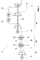
図1に、化石燃料火力発電プラントより生じる煙道ガスを処理するための煙道ガス処理システム1を示す。タービンを駆動する作動媒体を発生させるために化石燃料を燃焼させることにより生じる煙道ガスを誘導するライン2を除き、発電プラント自体は示されていない。処理システム1は、基本的に、煙道ガスを第1の圧縮機システムC1、熱回収システムHR、第2の圧縮機システムC2へと誘導する煙道ガスライン2と、分離されたCO2を更なる利用のための設備へと誘導するためのCO2ライン3とを備える。第1の圧縮機システムC1と、熱回収システムHRと、第2の圧縮機システムC2とはすべて、上述した順番で直列に配置される。煙道ガスライン2は発電プラントから第1の圧縮機システムC1へと通じている。第1の圧縮機システムC1は、煙道ガス断熱圧縮機5を備える。熱回収システムHRは、圧縮機C1から放出される圧縮された煙道ガスを冷却するため及び煙道ガスから発電プラントへの熱移動を行うための熱交換器を備える。第2の圧縮機システムC2は、煙道ガスを低圧圧縮するため及び精製されたCO2を高圧圧縮するための結合多段式中間冷却式圧縮機システムを備える。最後に、ライン3は、精製・圧縮されたCO2がシステム1を離れ、輸送、貯蔵又は石油増進回収等のCO2の更なる利用のための更なるシステム4へと導く。
FIG. 1 shows a flue gas treatment system 1 for treating flue gas generated from a fossil fuel thermal power plant. The power plant itself is not shown, except for
図示したように、煙道ガスは、ライン2経由でシステム1に導かれる。ライン2において、煙道ガスは、例えば、石炭焚きボイラー、ガス燃焼室、又は酸素吹石炭焚きボイラーより生じたものである。そのため、このような煙道ガスは、煙道ガス再循環を行う又は行わないガスタービン発電プラントの場合における4%以上や、蒸気タービン発電プラント用の酸素吹石炭焚ボイラーの場合における最大60〜90%等様々な濃度でCO2ガスを含む。このボイラー又は燃焼室の後で、煙道ガスは、静電集塵機や織布フィルターのようなフィルターや、他の硫黄除去のための任意の処理ユニットにおいて前処理されていてもよい。更に、煙道ガスは、NOx又は水銀を除去するための装置において、処理されていてもよい。
As shown, flue gas is directed to system 1 via
煙道ガスライン2は、CO2含有煙道ガスを、駆動装置6により駆動され煙道ガスを5から20bar absまでの吐出圧力まで圧縮するよう構成された低圧煙道ガス断熱圧縮機5へと運ぶ。圧縮の動力消費量が最小化されるのは、吐出圧力が5から8bar absまで、例えば7bar absとなるよう構成したときである。断熱圧縮機5は20barを越えない吐出圧力まで圧縮を行うように構成される。この限界を超える吐出圧力まで圧縮すると、断熱圧縮機を使用することによる利点がもはや何ら無くなる程度まで動力消費量が増加する。これは、8bar abs程度の圧力以降では、断熱式(軸流式)動力消費量が、中間冷却式遠心圧縮機のそれを上回るようになるためである。この圧力以降では、軸流式装置においてより効率的なホイールを有するという利点が、中間冷却不在によるガス温度上昇による動力消費量の増加により相殺され、この増加が利点を上回るようになる。圧縮機の吐出時、圧縮された煙道ガスの温度はおよそ200℃〜280℃である。断熱圧縮機の最適な吐出圧力は、動力消費量を最小化することにより設定されることとなるが、水/蒸気サイクルの統合、もし存在するのならばSOx及びNOxの中間除去等の付属パラメーターや、装置の選択によっても設定される。
The
ライン7は、低圧煙道ガス圧縮機5の吐出部から第1の熱交換器8へと通じている。第1の熱交換器8内では、圧縮された高温煙道ガスは水又は他の冷媒の流れに対し向流で流れる。冷媒は、熱交換器8からライン9経由で発電プラント内のシステム内又は発電プラントに接続されたシステム内の熱回収のためのシステムへと導かれる。煙道ガス断熱/軸流式圧縮機5は、この場所で遠心圧縮機を代わりに用いた場合と比べ高い温度(170〜240℃)で煙道ガスから熱を回収することを可能にする。この熱は発電プラント内で有効に用いることができる。例えば、図示された実施形態においては、熱回収システムは、蒸気タービンシステムの水/蒸気サイクル9である。特定の一例において、この水流は、給水予熱器又は凝縮物抽出ポンプに接続される。凝縮物の一部は直接煙道ガスで加熱することができ、それにより、低圧加熱器を迂回できる。低圧加熱器の蒸気消費量は減少し、その結果、より多くの蒸気がサイクル蒸気タービン内で膨張するので、プラントはより多くの電力を生成できる。煙道ガス断熱/軸流式圧縮機を使用することにより、煙道ガス遠心式圧縮機のみを有する発電プラントの正味出力に対し、発電プラントの正味発電出力を0.5%から1%までの範囲で上昇させることができる。本発明に係る発電プラントは、遠心圧縮機のみを備える発電プラントと同数の圧縮装置を備えているにもかかわらず、より大きな出力を達成する。
The line 7 leads from the discharge part of the low-pressure
熱交換器8を通過後の煙道ガスの温度は例えば50℃である。煙道ガス側では、熱交換器8は、ライン10経由で、更なる熱交換器又は冷却器11に接続さている。そこで、煙道ガスは例えば30℃の温度まで更に冷却される。この冷却の結果得られる熱は低品位なものであり、散逸させてよい。
The temperature of the flue gas after passing through the
ライン13は、冷却器11から、駆動装置17により駆動される結合圧縮システムC2へと通じている。結合圧縮システムC2は、シャフト16上に配置され駆動装置17により駆動される低圧煙道ガス圧縮機14及び高圧CO2圧縮機15を備える。低圧煙道ガス圧縮機は、例えば、中間冷却器を備えた2段式の遠心圧縮機を有することができる。一方、高圧CO2圧縮機は、例えば、中間冷却器を備えた4〜6段を有することができる。断熱圧縮機の吐出圧力がより低い場合、すなわち、5〜20bar absの吐出圧力範囲にある場合、低圧煙道ガス遠心圧縮機は2段ではなく3段を有していてもよい。煙道ガスは、低圧圧縮機14により例えば30bar absの圧力に圧縮され、ライン18経由で脱水ユニット19へと導かれ、その後低温ユニット20へと導かれる。低温ユニットにおいて、煙道ガスは分離され、精製CO2ガス流、及び、窒素、酸素アルゴン等の不活性ガスを含むベントガスになる。ベントガスは、ライン21経由でエキスパンダー22へと送られる。エキスパンダー22は、同一のシャフト16に取り付けることも、独立したシャフトに取り付けることもできる。本発明に係る煙道ガス処理システムにおいては、低圧煙道ガス圧縮システム14と高圧CO2圧縮システム15とは同じシャフト上に配置される。一方で、低圧煙道ガス圧縮システムは、低温精製システムの上流に配置され、高圧CO2圧縮システムは精製システムの下流に配置される。
輸送や貯蔵に十分な濃度のCO2を主に含有するに至った低温精製された煙道ガスは、ユニット20から、110bar absの圧力へと更に圧縮するための高圧圧縮機システム15へと導かれる。そこから、精製された煙道ガスは最終的に、ライン3を経由して、CO2の更なる利用のためのシステム4へと導かれる。この低温処理は、精製CO2ガスが、それぞれ異なる2つの圧力の2つの別の流れとして圧縮機システム15へと供給される点で最適化することができる。これにより、圧縮機の動力消費量は最小化される。一方の第1の低圧ラインは、精製CO2ガスを圧縮機システム15の前部入口へと供給し、第2の中間圧力ラインは、精製CO2ガスを圧縮機システム15の中間段へと供給する。
The cryogenically purified flue gas, which has mainly contained CO 2 at a concentration sufficient for transport and storage, is led from the
1 煙道ガス処理用システム
2 発電プラントからの煙道ガスライン
3 精製CO2ガス用ライン
4 精製CO2の輸送、貯蔵又は更なる利用のためのシステム
5 断熱圧縮機
6 駆動装置
7 煙道ガスライン
8 熱交換器
9 冷媒用システム
10 煙道ガスライン
11 熱交換器
12 冷媒用システム
13 煙道ガスライン
14 煙道ガス用低圧圧縮機
15 CO2ガス用高圧圧縮機
16 シャフト
17 結合された低圧及び高圧圧縮機用駆動装置
18 煙道ガスライン
19 脱水ユニット
20 低温ユニット
21 不活性ガス用ライン
22 ベント不活性ガス用エキスパンダー
C1 断熱圧縮機
C2 結合圧縮装置
HR 熱回収システム
DESCRIPTION OF SYMBOLS 1 System for
Claims (13)
前記煙道ガス処理システムは、
中間冷却を行わない断熱軸流式圧縮機である第1の低圧煙道ガス圧縮機(5)と、
前記第1の低圧煙道ガス圧縮機(5)の下流に配置され、圧縮された前記煙道ガスから前記発電プラントへ又は前記発電プラントに接続されたシステムへの熱移動を行うように構成・配置された1つ以上の熱交換器(8,11)と、
前記1つ以上の熱交換器(8,11)の下流に配置され、1つ以上の段と1つ以上の冷却器とを有する第2の低圧煙道ガス圧縮機(14)と、
前記第2の低圧煙道ガス圧縮機(14)の下流に配置された、前記煙道ガスから不活性ガスを除去することにより前記煙道ガスを低温精製するためのユニット(20)と、
前記低温精製するためのユニット(20)の下流に配置され、前記低温精製するためのユニット(20)より生じるCO2流を圧縮するよう構成・配置された、幾つかの段と1つ以上の冷却器とを有する高圧CO2圧縮機システム(15)と
を備え、
前記第2の低圧煙道ガス圧縮機(14)と前記高圧CO2圧縮機システム(15)との両方は、単一の装置(C2)内で結合され、1つの共通駆動装置(17)により駆動される1本の共通シャフト(16)上に配置されていることを特徴とする化石燃料火力発電プラント。 In a fossil fuel thermal power plant for generating electrical energy comprising a system for treating flue gas resulting from the combustion of fossil fuels,
The flue gas treatment system comprises:
A first low-pressure flue gas compressor (5) that is an adiabatic axial flow compressor without intermediate cooling;
Located downstream of the first low pressure flue gas compressor (5) and configured to perform heat transfer from the compressed flue gas to the power plant or to a system connected to the power plant One or more heat exchangers (8, 11) arranged;
A second low pressure flue gas compressor (14) disposed downstream of the one or more heat exchangers (8, 11) and having one or more stages and one or more coolers;
A unit (20), disposed downstream of the second low pressure flue gas compressor (14), for cryogenically purifying the flue gas by removing inert gas from the flue gas;
One or more stages and one or more stages arranged downstream from the cryorefining unit (20) and configured and arranged to compress the CO 2 stream resulting from the cryorefining unit (20) A high pressure CO 2 compressor system (15) having a cooler,
Both the second low-pressure flue gas compressor (14) and the high-pressure CO 2 compressor system (15) are combined in a single device (C2) by a single common drive (17). A fossil fuel-fired power plant, which is arranged on one common shaft (16) to be driven.
前記高圧CO2圧縮機システム(15)は4〜6段の高圧圧縮機段を備え、
前記2段の低圧圧縮機段と前記4〜6段の高圧圧縮機段とは単一のシャフト上に配置されていることを特徴とする、請求項1に記載の発電プラント。 Said second low pressure flue gas compressor (14) comprises two low pressure compressor stages;
The high pressure CO 2 compressor system (15) comprises 4 to 6 high pressure compressor stages,
The power plant according to claim 1, wherein the two low-pressure compressor stages and the four to six high-pressure compressor stages are disposed on a single shaft.
前記高圧CO2圧縮機システム(15)は4〜6段の高圧圧縮機段を備え、
前記3段の低圧圧縮機段と前記4〜6段の高圧圧縮機段とは単一のシャフト上に配置されていることを特徴とする、請求項1に記載の発電プラント。 Said second low pressure flue gas compressor (14) comprises three low pressure compressor stages;
The high pressure CO 2 compressor system (15) comprises 4 to 6 high pressure compressor stages,
The power plant according to claim 1, wherein the three low-pressure compressor stages and the four to six high-pressure compressor stages are disposed on a single shaft.
中圧精製CO2ガス用の第2のラインが、前記低温精製ユニット(20)から前記高圧CO2圧縮システム(15)の中間段へと通じていることを特徴とする、請求項1〜10のいずれか1項に記載の発電プラント。 A first line for low pressure purified CO 2 gas leads from the low temperature purification unit (20) to a first inlet of the high pressure CO 2 compression system (15);
The second line for the medium pressure made CO 2 gas, characterized in that it leads to the intermediate stage of the high-pressure CO 2 compression system (15) from the low temperature purification unit (20), according to claim 1 to 10 The power plant according to any one of the above.
Applications Claiming Priority (3)
| Application Number | Priority Date | Filing Date | Title |
|---|---|---|---|
| EP09165304 | 2009-07-13 | ||
| EP09165304.8 | 2009-07-13 | ||
| PCT/EP2010/059971 WO2011006862A2 (en) | 2009-07-13 | 2010-07-12 | System for gas processing |
Publications (2)
| Publication Number | Publication Date |
|---|---|
| JP2012533025A true JP2012533025A (en) | 2012-12-20 |
| JP2012533025A5 JP2012533025A5 (en) | 2013-08-15 |
Family
ID=42101989
Family Applications (1)
| Application Number | Title | Priority Date | Filing Date |
|---|---|---|---|
| JP2012519990A Withdrawn JP2012533025A (en) | 2009-07-13 | 2010-07-12 | System for gas treatment |
Country Status (13)
| Country | Link |
|---|---|
| US (1) | US20120174622A1 (en) |
| EP (1) | EP2454545A2 (en) |
| JP (1) | JP2012533025A (en) |
| KR (1) | KR20120040710A (en) |
| CN (1) | CN102597672B (en) |
| AU (1) | AU2010272630B2 (en) |
| BR (1) | BR112012000811A2 (en) |
| CA (1) | CA2767938C (en) |
| IL (1) | IL217100A0 (en) |
| MA (1) | MA33510B1 (en) |
| RU (1) | RU2012104832A (en) |
| WO (1) | WO2011006862A2 (en) |
| ZA (1) | ZA201109440B (en) |
Cited By (1)
| Publication number | Priority date | Publication date | Assignee | Title |
|---|---|---|---|---|
| JP2014213298A (en) * | 2013-04-30 | 2014-11-17 | 株式会社Ihi | Method and apparatus of supplying alkaline modifier in compressor impurity separation mechanism |
Families Citing this family (21)
| Publication number | Priority date | Publication date | Assignee | Title |
|---|---|---|---|---|
| EP2559866B1 (en) | 2011-08-18 | 2014-01-01 | Alstom Technology Ltd | Power plant heat integration |
| EP2620732A1 (en) * | 2012-01-26 | 2013-07-31 | Linde Aktiengesellschaft | Method and device for air separation and steam generation in a combined system |
| FR2997478B3 (en) * | 2013-07-05 | 2015-05-01 | Air Liquide | METHOD FOR HEATING COMPRESSION FUMES FOR THE PURPOSE OF ACHIEVING THERMAL INTEGRATION BETWEEN A CO2 CAPTURE UNIT AND A GAS SEPARATION UNIT OF THE AIR. |
| EP2942495B1 (en) | 2014-05-08 | 2018-10-10 | General Electric Technology GmbH | Coal fired oxy plant with heat integration |
| EP2942497B1 (en) | 2014-05-08 | 2018-10-31 | General Electric Technology GmbH | Oxy boiler power plant oxygen feed system heat integration |
| EP2942496B1 (en) | 2014-05-08 | 2018-10-10 | General Electric Technology GmbH | Oxy boiler power plant with a heat integrated air separation unit |
| PL2942494T3 (en) | 2014-05-08 | 2020-03-31 | General Electric Technology Gmbh | Coal fired oxy plant with heat integration |
| US20190107280A1 (en) * | 2016-04-01 | 2019-04-11 | Sigma Energy Storage Inc. | Electrical power generation system |
| US10789657B2 (en) * | 2017-09-18 | 2020-09-29 | Innio Jenbacher Gmbh & Co Og | System and method for compressor scheduling |
| US10626067B1 (en) * | 2019-05-10 | 2020-04-21 | Uop Llc | Processes for separating para-xylene from toluene |
| CN110280391B (en) * | 2019-06-14 | 2021-02-02 | 珠海格力电器股份有限公司 | Dustproof control method and device, storage medium and wall-hanging stove controller |
| US11493029B2 (en) | 2021-04-02 | 2022-11-08 | Ice Thermal Harvesting, Llc | Systems and methods for generation of electrical power at a drilling rig |
| US11326550B1 (en) | 2021-04-02 | 2022-05-10 | Ice Thermal Harvesting, Llc | Systems and methods utilizing gas temperature as a power source |
| US11421663B1 (en) | 2021-04-02 | 2022-08-23 | Ice Thermal Harvesting, Llc | Systems and methods for generation of electrical power in an organic Rankine cycle operation |
| US11486370B2 (en) | 2021-04-02 | 2022-11-01 | Ice Thermal Harvesting, Llc | Modular mobile heat generation unit for generation of geothermal power in organic Rankine cycle operations |
| US11480074B1 (en) | 2021-04-02 | 2022-10-25 | Ice Thermal Harvesting, Llc | Systems and methods utilizing gas temperature as a power source |
| US11644015B2 (en) | 2021-04-02 | 2023-05-09 | Ice Thermal Harvesting, Llc | Systems and methods for generation of electrical power at a drilling rig |
| US11187212B1 (en) | 2021-04-02 | 2021-11-30 | Ice Thermal Harvesting, Llc | Methods for generating geothermal power in an organic Rankine cycle operation during hydrocarbon production based on working fluid temperature |
| US11592009B2 (en) | 2021-04-02 | 2023-02-28 | Ice Thermal Harvesting, Llc | Systems and methods for generation of electrical power at a drilling rig |
| US11293414B1 (en) | 2021-04-02 | 2022-04-05 | Ice Thermal Harvesting, Llc | Systems and methods for generation of electrical power in an organic rankine cycle operation |
| CN115405860A (en) * | 2022-08-17 | 2022-11-29 | 成都展望能源机械有限公司 | Explosion-proof type flue gas dehydration supercharging device |
Family Cites Families (15)
| Publication number | Priority date | Publication date | Assignee | Title |
|---|---|---|---|---|
| CH476205A (en) * | 1967-07-27 | 1969-07-31 | Sulzer Ag | Gas turbine system with CO2 as the working medium |
| US4977745A (en) * | 1983-07-06 | 1990-12-18 | Heichberger Albert N | Method for the recovery of low purity carbon dioxide |
| JPH0564722A (en) * | 1991-09-09 | 1993-03-19 | Hitachi Ltd | Separation of carbon dioxide in combustion exhaust gas |
| CA2317539C (en) * | 1998-01-08 | 2003-08-19 | Satish Reddy | Autorefrigeration separation of carbon dioxide |
| GB9801200D0 (en) * | 1998-01-20 | 1998-03-18 | Air Prod & Chem | Intergration of a cryogenic air separator with synthesis gas production and conversion |
| US6035662A (en) * | 1998-10-13 | 2000-03-14 | Praxair Technology, Inc. | Method and apparatus for enhancing carbon dioxide recovery |
| NO990812L (en) * | 1999-02-19 | 2000-08-21 | Norsk Hydro As | Method for removing and recovering CO2 from exhaust gas |
| EP1197717A1 (en) * | 2000-10-12 | 2002-04-17 | Linde Aktiengesellschaft | Process and apparatus for air separation |
| FR2827186A1 (en) * | 2001-07-12 | 2003-01-17 | Air Liquide | Compressor(s) in an air distillation unit supplying gas(es) to an industrial unit which produces steam are driven using the steam from the industrial unit and an electric motor |
| DE10360951A1 (en) * | 2003-12-23 | 2005-07-28 | Alstom Technology Ltd | Thermal power plant with sequential combustion and reduced CO2 emissions and method of operating such a plant |
| GB2416389B (en) * | 2004-07-16 | 2007-01-10 | Statoil Asa | LCD liquefaction process |
| US7416716B2 (en) * | 2005-11-28 | 2008-08-26 | Air Products And Chemicals, Inc. | Purification of carbon dioxide |
| US7827778B2 (en) * | 2006-11-07 | 2010-11-09 | General Electric Company | Power plants that utilize gas turbines for power generation and processes for lowering CO2 emissions |
| US20080127632A1 (en) * | 2006-11-30 | 2008-06-05 | General Electric Company | Carbon dioxide capture systems and methods |
| US7966829B2 (en) * | 2006-12-11 | 2011-06-28 | General Electric Company | Method and system for reducing CO2 emissions in a combustion stream |
-
2009
- 2009-07-12 US US13/383,620 patent/US20120174622A1/en not_active Abandoned
-
2010
- 2010-07-12 KR KR1020127003576A patent/KR20120040710A/en active IP Right Grant
- 2010-07-12 JP JP2012519990A patent/JP2012533025A/en not_active Withdrawn
- 2010-07-12 MA MA34607A patent/MA33510B1/en unknown
- 2010-07-12 RU RU2012104832/06A patent/RU2012104832A/en not_active Application Discontinuation
- 2010-07-12 CN CN201080032347.4A patent/CN102597672B/en not_active Expired - Fee Related
- 2010-07-12 AU AU2010272630A patent/AU2010272630B2/en not_active Expired - Fee Related
- 2010-07-12 EP EP10730184A patent/EP2454545A2/en not_active Withdrawn
- 2010-07-12 CA CA2767938A patent/CA2767938C/en not_active Expired - Fee Related
- 2010-07-12 BR BR112012000811A patent/BR112012000811A2/en not_active IP Right Cessation
- 2010-07-12 WO PCT/EP2010/059971 patent/WO2011006862A2/en active Application Filing
-
2011
- 2011-12-20 IL IL217100A patent/IL217100A0/en unknown
- 2011-12-21 ZA ZA2011/09440A patent/ZA201109440B/en unknown
Cited By (1)
| Publication number | Priority date | Publication date | Assignee | Title |
|---|---|---|---|---|
| JP2014213298A (en) * | 2013-04-30 | 2014-11-17 | 株式会社Ihi | Method and apparatus of supplying alkaline modifier in compressor impurity separation mechanism |
Also Published As
| Publication number | Publication date |
|---|---|
| BR112012000811A2 (en) | 2016-02-23 |
| MA33510B1 (en) | 2012-08-01 |
| CN102597672B (en) | 2015-08-05 |
| CA2767938A1 (en) | 2011-01-20 |
| KR20120040710A (en) | 2012-04-27 |
| WO2011006862A3 (en) | 2012-04-05 |
| ZA201109440B (en) | 2013-02-27 |
| US20120174622A1 (en) | 2012-07-12 |
| RU2012104832A (en) | 2013-08-20 |
| IL217100A0 (en) | 2012-02-29 |
| CN102597672A (en) | 2012-07-18 |
| EP2454545A2 (en) | 2012-05-23 |
| AU2010272630A1 (en) | 2012-02-09 |
| WO2011006862A2 (en) | 2011-01-20 |
| CA2767938C (en) | 2014-09-09 |
| AU2010272630B2 (en) | 2015-10-22 |
Similar Documents
| Publication | Publication Date | Title |
|---|---|---|
| JP2012533025A (en) | System for gas treatment | |
| US6282901B1 (en) | Integrated air separation process | |
| EP1827656B1 (en) | Method for removing and recovering co2 from an exhaust gas | |
| EP1690040B1 (en) | Method for co2 separation from thermal power plant combution gas | |
| RU2315186C2 (en) | Low contamination thermal power station | |
| US7827778B2 (en) | Power plants that utilize gas turbines for power generation and processes for lowering CO2 emissions | |
| ES2602428T3 (en) | Oxy-fuel combustion with integrated pollution control | |
| EP2431579B1 (en) | Multipurpose thermal power plant system | |
| EP2724767B1 (en) | A method of treating a carbon dioxide rich flue gas and a flue gas treatment system | |
| EA031165B1 (en) | System and method for high-efficiency energy generation using a nitrogen-based working fluid | |
| JP2014512471A (en) | Combined cycle power plant with CO2 capture plant | |
| JP2010507773A (en) | Method and apparatus for CO2 recovery in oxyfuel combustion | |
| JP2013533426A (en) | Jet engine with carbon capture | |
| CN109173558B (en) | Low-energy-consumption carbon dioxide capturing and sealing technology and system | |
| JP2012533025A5 (en) | ||
| JP2010112377A (en) | System and method for reducing corrosion in gas turbine system | |
| JP5448858B2 (en) | Oxy-combustion power plant and its operation method | |
| CN102388265A (en) | Method and apparatus for generating electrical power | |
| JP2013540229A (en) | Combined cycle power plant with CO2 capture and method of operating the same | |
| EP2559866B1 (en) | Power plant heat integration | |
| US11224837B2 (en) | Post-combustion carbon dioxide capture and compression | |
| Dickmeis et al. | Integration of oxygen-containing exhaust gas into the air separation unit of an oxyfuel power plant | |
| EP2815801A1 (en) | Flue gas treatment system and method |
Legal Events
| Date | Code | Title | Description |
|---|---|---|---|
| A521 | Request for written amendment filed |
Free format text: JAPANESE INTERMEDIATE CODE: A523 Effective date: 20130628 |
|
| A621 | Written request for application examination |
Free format text: JAPANESE INTERMEDIATE CODE: A621 Effective date: 20130628 |
|
| RD03 | Notification of appointment of power of attorney |
Free format text: JAPANESE INTERMEDIATE CODE: A7423 Effective date: 20130814 |
|
| RD04 | Notification of resignation of power of attorney |
Free format text: JAPANESE INTERMEDIATE CODE: A7424 Effective date: 20131008 |
|
| A761 | Written withdrawal of application |
Free format text: JAPANESE INTERMEDIATE CODE: A761 Effective date: 20131031 |